US9592127B2 - Distal femoral knee prostheses - Google Patents

Distal femoral knee prostheses Download PDF

Info

Publication number
US9592127B2
US9592127B2 US11/611,021 US61102106A US9592127B2 US 9592127 B2 US9592127 B2 US 9592127B2 US 61102106 A US61102106 A US 61102106A US 9592127 B2 US9592127 B2 US 9592127B2
Authority
US
United States
Prior art keywords
anterior
prostheses
distal
overall
posterior
Prior art date
Legal status (The legal status is an assumption and is not a legal conclusion. Google has not performed a legal analysis and makes no representation as to the accuracy of the status listed.)
Active, expires
Application number
US11/611,021
Other versions
US20070260323A1 (en
Inventor
Brian D. Earl
Abraham P. Habegger
Aaron A. Hoffman
Kim C. Bertin
Lawrence Dorr
Robert E. Booth, Jr.
Aaron Rosenberg
Sergio Romagnoli
Current Assignee (The listed assignees may be inaccurate. Google has not performed a legal analysis and makes no representation or warranty as to the accuracy of the list.)
Zimmer Inc
Original Assignee
Zimmer Inc
Priority date (The priority date is an assumption and is not a legal conclusion. Google has not performed a legal analysis and makes no representation as to the accuracy of the date listed.)
Filing date
Publication date
Application filed by Zimmer Inc filed Critical Zimmer Inc
Priority to US11/611,021 priority Critical patent/US9592127B2/en
Assigned to ZIMMER, INC. reassignment ZIMMER, INC. ASSIGNMENT OF ASSIGNORS INTEREST (SEE DOCUMENT FOR DETAILS). Assignors: HABEGGER, ABRAHAM P., EARL, BRIAN D.
Priority to US11/780,248 priority patent/US20080058947A1/en
Publication of US20070260323A1 publication Critical patent/US20070260323A1/en
Assigned to ZIMMER, INC. reassignment ZIMMER, INC. ASSIGNMENT OF ASSIGNORS INTEREST (SEE DOCUMENT FOR DETAILS). Assignors: HOFMANN, AARON A.
Assigned to ZIMMER, INC. reassignment ZIMMER, INC. ASSIGNMENT OF ASSIGNORS INTEREST (SEE DOCUMENT FOR DETAILS). Assignors: ROSENBERG, AARON
Assigned to ZIMMER, INC. reassignment ZIMMER, INC. ASSIGNMENT OF ASSIGNORS INTEREST (SEE DOCUMENT FOR DETAILS). Assignors: DORR, LAWRENCE D.
Assigned to ZIMMER, INC. reassignment ZIMMER, INC. ASSIGNMENT OF ASSIGNORS INTEREST (SEE DOCUMENT FOR DETAILS). Assignors: BERTIN, KIM C.
Assigned to ZIMMER, INC. reassignment ZIMMER, INC. ASSIGNMENT OF ASSIGNORS INTEREST (SEE DOCUMENT FOR DETAILS). Assignors: BOOTH, ROBERT E.
Priority to US12/974,018 priority patent/US20110093083A1/en
Priority to US15/424,382 priority patent/US10433966B2/en
Publication of US9592127B2 publication Critical patent/US9592127B2/en
Application granted granted Critical
Active legal-status Critical Current
Adjusted expiration legal-status Critical

Links

Images

Classifications

    • AHUMAN NECESSITIES
    • A61MEDICAL OR VETERINARY SCIENCE; HYGIENE
    • A61FFILTERS IMPLANTABLE INTO BLOOD VESSELS; PROSTHESES; DEVICES PROVIDING PATENCY TO, OR PREVENTING COLLAPSING OF, TUBULAR STRUCTURES OF THE BODY, e.g. STENTS; ORTHOPAEDIC, NURSING OR CONTRACEPTIVE DEVICES; FOMENTATION; TREATMENT OR PROTECTION OF EYES OR EARS; BANDAGES, DRESSINGS OR ABSORBENT PADS; FIRST-AID KITS
    • A61F2/00Filters implantable into blood vessels; Prostheses, i.e. artificial substitutes or replacements for parts of the body; Appliances for connecting them with the body; Devices providing patency to, or preventing collapsing of, tubular structures of the body, e.g. stents
    • A61F2/02Prostheses implantable into the body
    • A61F2/30Joints
    • A61F2/38Joints for elbows or knees
    • A61F2/3859Femoral components
    • AHUMAN NECESSITIES
    • A61MEDICAL OR VETERINARY SCIENCE; HYGIENE
    • A61FFILTERS IMPLANTABLE INTO BLOOD VESSELS; PROSTHESES; DEVICES PROVIDING PATENCY TO, OR PREVENTING COLLAPSING OF, TUBULAR STRUCTURES OF THE BODY, e.g. STENTS; ORTHOPAEDIC, NURSING OR CONTRACEPTIVE DEVICES; FOMENTATION; TREATMENT OR PROTECTION OF EYES OR EARS; BANDAGES, DRESSINGS OR ABSORBENT PADS; FIRST-AID KITS
    • A61F2/00Filters implantable into blood vessels; Prostheses, i.e. artificial substitutes or replacements for parts of the body; Appliances for connecting them with the body; Devices providing patency to, or preventing collapsing of, tubular structures of the body, e.g. stents
    • A61F2/02Prostheses implantable into the body
    • A61F2/30Joints
    • A61F2002/30001Additional features of subject-matter classified in A61F2/28, A61F2/30 and subgroups thereof
    • A61F2002/30316The prosthesis having different structural features at different locations within the same prosthesis; Connections between prosthetic parts; Special structural features of bone or joint prostheses not otherwise provided for
    • A61F2002/30317The prosthesis having different structural features at different locations within the same prosthesis
    • A61F2002/30324The prosthesis having different structural features at different locations within the same prosthesis differing in thickness
    • AHUMAN NECESSITIES
    • A61MEDICAL OR VETERINARY SCIENCE; HYGIENE
    • A61FFILTERS IMPLANTABLE INTO BLOOD VESSELS; PROSTHESES; DEVICES PROVIDING PATENCY TO, OR PREVENTING COLLAPSING OF, TUBULAR STRUCTURES OF THE BODY, e.g. STENTS; ORTHOPAEDIC, NURSING OR CONTRACEPTIVE DEVICES; FOMENTATION; TREATMENT OR PROTECTION OF EYES OR EARS; BANDAGES, DRESSINGS OR ABSORBENT PADS; FIRST-AID KITS
    • A61F2/00Filters implantable into blood vessels; Prostheses, i.e. artificial substitutes or replacements for parts of the body; Appliances for connecting them with the body; Devices providing patency to, or preventing collapsing of, tubular structures of the body, e.g. stents
    • A61F2/02Prostheses implantable into the body
    • A61F2/30Joints
    • A61F2002/30001Additional features of subject-matter classified in A61F2/28, A61F2/30 and subgroups thereof
    • A61F2002/30316The prosthesis having different structural features at different locations within the same prosthesis; Connections between prosthetic parts; Special structural features of bone or joint prostheses not otherwise provided for
    • A61F2002/30535Special structural features of bone or joint prostheses not otherwise provided for
    • A61F2002/30604Special structural features of bone or joint prostheses not otherwise provided for modular
    • A61F2002/30616Sets comprising a plurality of prosthetic parts of different sizes or orientations
    • AHUMAN NECESSITIES
    • A61MEDICAL OR VETERINARY SCIENCE; HYGIENE
    • A61FFILTERS IMPLANTABLE INTO BLOOD VESSELS; PROSTHESES; DEVICES PROVIDING PATENCY TO, OR PREVENTING COLLAPSING OF, TUBULAR STRUCTURES OF THE BODY, e.g. STENTS; ORTHOPAEDIC, NURSING OR CONTRACEPTIVE DEVICES; FOMENTATION; TREATMENT OR PROTECTION OF EYES OR EARS; BANDAGES, DRESSINGS OR ABSORBENT PADS; FIRST-AID KITS
    • A61F2/00Filters implantable into blood vessels; Prostheses, i.e. artificial substitutes or replacements for parts of the body; Appliances for connecting them with the body; Devices providing patency to, or preventing collapsing of, tubular structures of the body, e.g. stents
    • A61F2/02Prostheses implantable into the body
    • A61F2/30Joints
    • A61F2002/30001Additional features of subject-matter classified in A61F2/28, A61F2/30 and subgroups thereof
    • A61F2002/30667Features concerning an interaction with the environment or a particular use of the prosthesis

Definitions

  • the present invention relates generally to orthopedic prosthetic devices and, in particular, to distal femoral knee prostheses.
  • TKR total knee replacement
  • TKA total knee arthroplasty
  • distal femoral knee prostheses are provided in a range of varying sizes and are selected by surgeons to best fit the anatomy of a particular patient, improvements in the design of distal femoral knee prostheses are desired.
  • the present disclosure provides a set of distal femoral prostheses particularly adapted for female anatomy, each femoral prosthesis including a distal nonarticulating surface having an anterior end and a posterior end, including a plurality of standard aspect ratio prostheses respectively having increasingly greater overall anterior/posterior dimensions defined between points located most anteriorly and most posteriorly on each prosthesis and having increasingly greater distal taper angles defined between a lateral line connecting the anterior end and the posterior end of the distal nonarticulating surface and a medial line connecting the anterior end and the posterior end of the distal nonarticulating surface on each prosthesis; at least some of the prostheses having a distal taper angle greater than or equal to approximately 21°.
  • each femoral prosthesis including a distal nonarticulating surface having an anterior end and a posterior end, including a plurality of standard aspect ratio prostheses each having an overall anterior/posterior dimension defined between points located most anteriorly and most posteriorly on each prosthesis and a medial/lateral dimension defined between points located most medially and most laterally at anterior/posterior locations substantially equidistant from the anterior end of the distal nonarticulating surface and the posterior end of the distal nonarticulating surface; at least some of the prostheses having an overall anterior/posterior dimension and a medial/lateral dimension falling below a conceptual boundary defined by a line connecting a first point and a second point, the first point having an approximately 52.0 overall anterior/posterior dimension and an approximately 55.0 medial/lateral dimension, and the second point having an approximately 77.0 overall anterior/posterior dimension and an approximately 78.5 medial/lateral dimension; wherein the line is
  • each femoral prosthesis including a distal nonarticulating surface having an anterior end and a posterior end, including a plurality of standard aspect ratio prostheses respectively having increasingly greater overall anterior/posterior dimensions defined between points located most anteriorly and most posteriorly on each prosthesis and respectively having increasingly greater medial/lateral dimensions defined between points located most medially and most laterally at an anterior/posterior location defined by the anterior end of the distal nonarticulating surface on each prosthesis; at least some of the prostheses having an overall anterior/posterior dimension and a medial/lateral dimension falling below a conceptual boundary defined by a line connecting a first point and a second point, the first point having an approximately 52.0 overall anterior/posterior dimension and an approximately 50.0 medial/lateral dimension, and the second point having an approximately 77.0 overall anterior/posterior dimension and an approximately 70.5 medial/lateral dimension; wherein the line is defined by the following equation: (medial)
  • each femoral prosthesis including a distal nonarticulating surface and an anterior nonarticulating surface, including a plurality of standard aspect ratio prostheses respectively having increasingly greater overall anterior/posterior dimensions defined between points located most anteriorly and most posteriorly on each prosthesis and respectively having increasingly greater medial/lateral dimensions defined between points located most medially and most laterally at an anterior/posterior location defined by a distal most point on the anterior nonarticulating surface on each prosthesis; at least some of the prostheses having an overall anterior/posterior dimension and a medial/lateral dimension falling below a conceptual boundary defined by a line connecting a first point and a second point, the first point having an approximately 52.0 overall anterior/posterior dimension and an approximately 40.1 medial/lateral dimension, and the second point having an approximately 77.0 overall anterior/posterior dimension and an approximately 53.5 medial/lateral dimension; wherein the line is defined by the following equation: (medial)
  • the present disclosure provides a set of distal femoral prostheses particularly adapted for female anatomy, each femoral prosthesis including a distal nonarticulating surface and an anterior nonarticulating surface, including a plurality of prostheses respectively having increasingly greater overall anterior/posterior dimensions defined between points located most anteriorly and most posteriorly on each prosthesis and respectively having increasingly greater medial/lateral dimensions defined between points located most medially and most laterally at an anterior/posterior location defined by a distal most point on the anterior nonarticulating surface on each prosthesis; at least some of the prostheses having an overall anterior/posterior dimension and a medial/lateral dimension falling below a conceptual boundary defined by a line connecting a first point and a second point, the first point having an approximately 52.0 overall anterior/posterior dimension and an approximately 40.3 medial/lateral dimension, and the second point having an approximately 77.0 overall anterior/posterior dimension and an approximately 51.8 medial/lateral dimension; wherein the line is defined by the following equation: (medial/lateral dimension)
  • each femoral prosthesis including a distal nonarticulating surface having an anterior end and a posterior end, including a plurality of prostheses each having an overall anterior/posterior dimension defined between points located most anteriorly and most posteriorly on each prosthesis and a medial/lateral dimension defined between points located most medially and most laterally at anterior/posterior locations substantially equidistant from the anterior end of the distal nonarticulating surface and the posterior end of the distal nonarticulating surface; at least some of the overall anterior/posterior dimensions and the medial/lateral dimensions falling within a conceptual boundary defined by an upper line and a lower line, the upper line connecting a first point and a third point, the lower line connecting a second point and a fourth point, the first point having an approximately 52.0 overall anterior/posterior dimension and an approximately 55.0 medial/lateral dimension, the second point having an approximately 52.0 overall anterior/posterior dimension
  • the present disclosure provides a set of distal femoral prostheses particularly adapted for female anatomy, each femoral prosthesis including a distal nonarticulating surface having an anterior end and a posterior end, including a plurality of standard aspect ratio prostheses respectively having increasingly greater overall anterior/posterior dimensions defined between points located most anteriorly and most posteriorly on each prosthesis and having increasingly greater medial/lateral dimensions defined between points located most medially and most laterally at an anterior/posterior location substantially equidistant from the anterior end of the distal nonarticulating surface and the posterior end of the distal nonarticulating surface on each prosthesis; the medial/lateral dimensions of the prostheses respectively increasing at a first rate, the overall anterior/posterior dimensions respectively increasing at a second rate, the first rate and the second rate defining a ratio substantially equal to or less than 0.89.
  • each femoral prosthesis including a distal nonarticulating surface having an anterior end and a posterior end, including a plurality of prostheses respectively having increasingly greater overall anterior/posterior dimensions defined between points located most anteriorly and most posteriorly on each prosthesis and having increasingly greater medial/lateral dimensions defined between points located most medially and most laterally at an anterior/posterior location substantially equidistant from the anterior end of the distal nonarticulating surface and the posterior end of the distal nonarticulating surface on each prosthesis; the medial/lateral dimensions of the prostheses respectively increasing at a first rate, the overall anterior/posterior dimensions respectively increasing at a second rate, the first rate and the second rate defining a ratio substantially equal to or less than 0.75.
  • the present disclosure provides a set of distal femoral prostheses particularly adapted for female anatomy, including a plurality of standard aspect ratio prostheses respectively having increasingly greater overall anterior/posterior dimensions defined between points located most anteriorly and most posteriorly on each prosthesis and having increasingly greater medial/lateral dimensions defined between points located most medially and most laterally at an anterior/posterior location defined at a location proximate the most posteriorly located point on each prosthesis; the medial/lateral dimensions of the prostheses respectively increasing at a first rate, the overall anterior/posterior dimensions respectively increasing at a second rate, the first rate and the second rate defining a ratio substantially equal to or less than 0.96.
  • the present disclosure provides a set of distal femoral prostheses particularly adapted for female anatomy, including a plurality of prostheses respectively having increasingly greater overall anterior/posterior dimensions defined between points located most anteriorly and most posteriorly on each prosthesis and having increasingly greater medial/lateral dimensions defined between points located most medially and most laterally at an anterior/posterior location defined at a location proximate the most posteriorly located point on each prosthesis; the medial/lateral dimensions of the prostheses respectively increasing at a first rate, the overall anterior/posterior dimensions respectively increasing at a second rate, the first rate and the second rate defining a ratio substantially equal to or less than 0.84.
  • each femoral prosthesis including a distal nonarticulating surface having an anterior end and a posterior end, including a plurality of standard aspect ratio prostheses respectively having increasingly greater overall anterior/posterior dimensions defined between points located most anteriorly and most posteriorly on each prosthesis and respectively having increasingly greater medial/lateral dimensions defined between points located most medially and most laterally at an anterior/posterior location defined by the anterior end of the distal nonarticulating surface on each prosthesis; the medial/lateral dimensions of the prostheses respectively increasing at a first rate, the overall anterior/posterior dimensions respectively increasing at a second rate, the first rate and the second rate defining a ratio substantially equal to or less than 0.78.
  • the present disclosure provides a set of distal femoral prostheses particularly adapted for female anatomy, each femoral prosthesis including a distal nonarticulating surface having an anterior end and a posterior end, including a plurality of prostheses respectively having increasingly greater overall anterior/posterior dimensions defined between points located most anteriorly and most posteriorly on each prosthesis and respectively having increasingly greater medial/lateral dimensions defined between points located most medially and most laterally at an anterior/posterior location defined by the anterior end of the distal nonarticulating surface on each prosthesis; the medial/lateral dimensions of the prostheses respectively increasing at a first rate, the overall anterior/posterior dimensions respectively increasing at a second rate, the first rate and the second rate defining a ratio substantially equal to or less than 0.76.
  • the present disclosure provides a set of distal femoral prostheses particularly adapted for female anatomy, each femoral prosthesis including a distal nonarticulating surface and an anterior nonarticulating surface, including a plurality of standard aspect ratio prostheses respectively having increasingly greater overall anterior/posterior dimensions defined between points located most anteriorly and most posteriorly on each prosthesis and respectively having increasingly greater medial/lateral dimensions defined between points located most medially and most laterally at an anterior/posterior location defined by a distal most point on the anterior nonarticulating surface on each prosthesis; the medial/lateral dimensions of the prostheses respectively increasing at a first rate, the overall anterior/posterior dimensions respectively increasing at a second rate, the first rate and the second rate defining a ratio substantially equal to or less than 0.44.
  • each femoral prosthesis including a distal nonarticulating surface having an anterior end and a posterior end, including a plurality of prostheses respectively having increasingly greater overall anterior/posterior dimensions defined between points located most anteriorly and most posteriorly on each prosthesis and having increasingly greater distal taper angles defined between a lateral line connecting the anterior end and the posterior end of the distal nonarticulating surface and a medial line connecting the anterior end and the posterior end of the distal nonarticulating surface on each prosthesis; the distal taper angles of the prostheses respectively increasing at a first rate, the overall anterior/posterior dimensions of the prostheses respectively increasing at a second rate, the first rate and the second rate defining a ratio substantially equal to or greater than 0.22.
  • each femoral prosthesis including a distal nonarticulating surface having an anterior end and a posterior end, including a plurality of prostheses respectively having increasingly greater overall anterior/posterior dimensions defined between points located most anteriorly and most posteriorly on each prosthesis and having increasingly greater distal taper angles defined between a lateral line connecting the anterior end and the posterior end of the distal nonarticulating surface and a medial line connecting the anterior end and the posterior end of the distal nonarticulating surface on each prosthesis; at least some of the overall anterior/posterior dimensions and the distal taper angles falling within a conceptual boundary defined by an upper boundary and a lower boundary, the upper boundary defined by a line connecting a first point and a third point, the lower boundary defined by a line connecting a second point and a fourth point, the first point having an approximately 52.0 overall anterior/posterior dimension and an approximately 27.0° distal taper angle, the second point having
  • each femoral prosthesis including a distal nonarticulating surface having an anterior end and a posterior end, including a plurality of prostheses respectively having increasingly greater overall anterior/posterior dimensions defined between points located most anteriorly and most posteriorly on each prosthesis and having increasingly greater distal taper angles defined between a lateral line connecting the anterior end and the posterior end of the distal nonarticulating surface and a medial line connecting the anterior end and the posterior end of the distal nonarticulating surface on each prosthesis; at least some of the overall anterior/posterior dimensions and the distal taper angles falling within a conceptual boundary defined by an upper boundary and a lower boundary, the upper boundary defined by a line connecting a first point and a third point, the lower boundary defined by a line connecting a second point and a fourth point, the first point having an approximately 52.0 overall anterior/posterior dimension and an approximately 34.0° distal taper angle, the second point having
  • the present disclosure provides a distal femoral prosthesis, including a non-articulating surface including a distal plane and an anterior non-articular surface; lateral and medial anterior condyles; a patellar sulcus defined between the condyles, the patellar sulcus having a maximum thickness between approximately 2.5 mm and 3.2 mm between an anterior most point on the sulcus and the anterior non-articular surface.
  • the present disclosure provides a distal femoral prosthesis, including a non-articulating surface including a distal plane and an anterior non-articular surface; lateral and medial anterior condyles each defining an anterior articular surface, at least one of the condyles having a maximum thickness between approximately 4.0 mm and 6.1 mm between an anterior most point on the anterior articular surface of the condyle and the anterior non-articular surface.
  • the present disclosure provides a distal femoral prosthesis, including a patellar sulcus disposed between lateral and medial anterior condyles of the prosthesis, the sulcus having an end point; a non-articulating surface having a distal plane; and a lateralization distance defined at the end point between a first line extending from an intersection of the distal plane and the sulcus and the end point, the lateralization distance greater than 5.0 mm.
  • FIG. 1 is a side view of an exemplary distal femoral prosthesis in accordance with the present invention
  • FIG. 2 is another side view of the prosthesis of FIG. 1 , illustrating certain dimensions thereof;
  • FIG. 3 is a distal view of the prosthesis of FIG. 2 , viewed along line 3 - 3 of FIG. 2 and shown superimposed on a known prosthesis;
  • FIG. 4 further illustrates the anatomical M/L vs. A/P dimensional relationship of the prosthesis of FIG. 3 at dimension “B-B”;
  • FIG. 5 is a graph illustrating a representative anatomical mid-box M/L vs. A/P dimensional relationship with respect to male and female femurs of various size;
  • FIG. 5A is a view of an anatomic overall A/P dimension for a representative femur
  • FIG. 5B is a view of an anatomic mid-box M/L dimension for a representative femur
  • FIG. 6 is a graph of mid-box M/L vs. overall A/P for prostheses designed in accordance with the present invention as compared with several known prostheses;
  • FIG. 7 is a graph of anterior M/L along a dimension “B-B” vs. overall A/P for prostheses designed in accordance with the present invention as compared with several known prostheses;
  • FIG. 8 is a graph of posterior M/L vs. overall A/P for prostheses designed in accordance with the present invention as compared with several known prostheses;
  • FIG. 9 is a graph of the ratio of (mid-box M/L/overall A/P) vs. overall A/P for the prostheses of FIG. 6 ;
  • FIG. 10 is a graph of the ratio of (anterior M/L along dimension “B-B”/overall A/P) vs. overall A/P for the prostheses of FIG. 7 ;
  • FIG. 11 is a graph of the ratio of (posterior M/L/overall A/P) vs. overall A/P for the prostheses of FIG. 8 ;
  • FIG. 12 is a distal view of an exemplary prosthesis designed in accordance with the present invention, shown superimposed on a known prosthesis and illustrating the profiles and the distal taper angles of same;
  • FIG. 13 is a graph of distal taper angle vs. overall A/P for prostheses designed in accordance with the present invention as compared with several known prostheses;
  • FIG. 14 is a distal view of an exemplary prosthesis
  • FIG. 15 is a side view of the prosthesis of FIG. 14 , illustrating the recessed patellar sulcus thereof as compared with a known prosthesis;
  • FIG. 16 is another side view of the prosthesis of FIG. 14 , illustrating the reduced profile of the anterior condyles thereof as compared with a known prosthesis;
  • FIG. 17A is an A/P view of a known prosthesis having conventional sulcus tracking
  • FIG. 17B is an A/P view of an exemplary prosthesis in accordance with the present invention having a more lateralized sulcus tracking;
  • FIG. 18 is a graph of A-A M/L vs. overall A/P for prostheses designed in accordance with the present invention as compared with several known prostheses;
  • FIG. 19 is a graph of the ratio of (A-A M/L/overall A/P) vs. overall A/P for the prostheses of FIG. 18 .
  • anterior and distal mean nearer to or further from the root of a structure, respectively.
  • distal femur is a part of the knee joint while the proximal femur is part of the hip joint.
  • medial and lateral mean nearer the sagittal plane or further from the sagittal plane, respectfully.
  • the sagittal plane is an imaginary vertical plane through the middle of the body that divides the body into right and left halves.
  • Distal femoral knee prostheses made in accordance with the present invention are intended to be used to restore knee joint function in patients with severe pain and disability due, for example, to Rheumatoid arthritis, osteoarthritis, traumatic arthritis polyarthritis; collagen disorders, and/or avascular necrosis of the femoral condyle; post-traumatic loss of joint configuration, particularly when there is patellofemoral erosion, dysfunction or prior patellectomy; moderate valgus, varus, flexion deformities, or other conditions.
  • a distal femoral prosthesis 50 for a TKR/TKA is shown, and generally includes an external articulating surface 52 and a bone contacting non-articulating internal surface 54 .
  • Articulating surface 52 includes an anterior articulating surface 56 , a distal articulating surface 58 , a lateral posterior condylar articulating surface 60 , and a medial posterior condylar articulating surface 62 .
  • Prosthesis 50 may be made of any biocompatible material having the mechanical properties necessary to function as a human knee distal femoral prosthesis.
  • prosthesis 50 is made of titanium, titanium alloy, cobalt chrome alloy, stainless steel, or a ceramic.
  • prosthesis 50 further includes patellar flange 64 including lateral and medial anterior condyles 66 and 68 , respectively, as well as patellar sulcus 70 disposed between lateral and medial anterior condyles 66 and 68 .
  • Prosthesis also includes lateral and medial posterior condyles 72 and 74 , respectively.
  • the internal non-articulating portion 54 of prosthesis 50 is adapted to receive a resected distal femur.
  • the surgical cuts made to the distal femur can be made by any means, in any sequence and in any configuration known to those of skill in the art of knee arthroplasty. Exemplary cut guides and processes for resecting the distal femur are shown and described in U.S. patent application Ser. No. 11/151,062, entitled ADJUSTABLE CUT GUIDE, filed on Jun. 13, 2005 and U.S. patent application Ser. No. 11/154,774, entitled MULTI-POSITIONABLE CUT GUIDE, filed on Jun. 16, 2005, assigned to the assignee of the present invention, the disclosures of which are expressly incorporated herein by reference.
  • prosthesis 50 comprises a plurality of chamfer surfaces corresponding to a plurality of chamfer surfaces or “box cuts” made in the distal femur.
  • Non-articular surface 54 may comprise a porous metal surface or any surface likely to promote the growth of bone therein.
  • Non-articular surface 54 of prosthesis 50 preferably comprises anterior non-articular surface 76 , distal anterior non-articular surface 78 , distal non-articular surface 80 , two distal posterior non-articular surfaces 82 , and two posterior non-articular surfaces 84 .
  • Distal non-articular surface 80 is generally flat and adapted to receive the distal-most surface of the resected femur.
  • Distal non-articular surface 80 comprises an anterior end and a posterior end. The anterior end of distal non-articular surface 80 abuts one end of distal anterior non-articular surface 78 , which surface 78 also includes an anterior end and a posterior end.
  • Surface 78 extends from surface 80 anteriorly and superiorly such that an obtuse angle is formed between surfaces 78 and 80 .
  • Anterior non-articular surface 76 extends superiorly from the anterior end of surface 78 .
  • distal non-articular surface 80 abuts one end of each distal posterior non-articular surface 82 , which surfaces 82 also include an anterior end and a posterior end.
  • Surfaces 82 extend from surface 80 posteriorly and superiorly such that an obtuse angle is formed between surfaces 82 and 80 .
  • Posterior non-articular surfaces 84 extend superiorly from the posterior ends of surfaces 82 , respectively.
  • prostheses 50 As discussed in detail below, for many patients, particularly female patients, it is desirable to construct a set of prostheses 50 of varying size wherein the medial/lateral (“M/L”) width dimensions of the prostheses correspond more closely to the actual anatomical M/L width dimensions of the female femur and articulating surfaces.
  • M/L medial/lateral
  • prostheses 50 addresses this concern by offering the surgeon a set of narrower prostheses in the M/L dimensions for a given set of anterior/posterior (“A/P”) prosthesis sizes which will allow the surgeon to use a prosthesis with both a correct A/P size and more accurate and optimized M/L dimensions to provide optimal prosthesis sizing and joint kinematics as compared to conventional prostheses.
  • A/P anterior/posterior
  • prosthesis 50 has a unique, substantially trapezoidal shape or profile 86 when viewed distally with a more pronounced narrowing of the M/L dimensions as compared to the shape or profile 88 of a known prosthesis starting, with reference to the resected femur, at the posterior distal facet and progressing anteriorly to the anterior distal facet.
  • prosthesis 50 is shown and is characterized below with reference to the following directions: anterior “A”, posterior “P”, distal “D”, proximal “PR”, medial “M” and lateral “L”, as well as the following dimensions.
  • Dimension “Posterior” is the M/L width at the widest point across the posterior condyles 72 , 74 of prosthesis 50 .
  • Dimension “C-C” is the M/L width at the junction of the posterior distal facet and the distal plane, i.e., the M/L width along the intersection between distal non-articular surface 80 and distal posterior non-articular surfaces 82 .
  • Dimension “B-B” is the M/L width at the junction of the distal plane and the distal anterior facet, i.e., the M/L width along the intersection between distal non-articular surface 80 and distal anterior non-articular surface 78 .
  • Dimension “A-A” is the M/L width at the junction of the distal anterior facet and the posterior side of the anterior flange, i.e., the M/L width along the intersection of distal anterior non-articular surface 78 and anterior non-articular surface 76 .
  • Dimension “MB” is the M/L width at a “mid-box” point of prosthesis 50 , i.e., along a line located on distal non-articular surface 80 substantially midway between Dimension C-C and Dimension B-B.
  • the profiles of a set of prostheses 50 can also be described in terms of an increasing narrowing of the M/L dimensions relative to known prostheses on a per size basis. It has been observed that, for given female femurs, for example, the M/L dimensions are sometimes smaller than those of known prostheses of the proper A/P dimension. This discrepancy is small on the smaller A/P size prostheses and increases as the A/P size increases. For example, referring to FIG. 5 , a representative mid-box M/L vs. A/P dimensional relationship with respect to the actual human anatomy of distal femurs for males and females is shown.
  • Representative female data is generally grouped together at lower values of mid-box M/L and representative male data is generally grouped together at higher values of mid-box M/L. Best fit lines for female and male data have been included on FIG. 5 to show the general trend of representative mid-box M/L dimensions. As may be seen from FIG. 5 , there exists a clear distinction between the representative M/L dimension vs. the A/P dimension for a female distal femur as compared to a male distal femur.
  • FIGS. 5A and 5B show exemplary anatomic overall A/P and mid-box M/L dimensions for a representative femur.
  • the overall A/P (“Overall A/P”) dimension is the distance between two lines perpendicular to distal non-articular surface 80 that pass through the most posterior point on the posterior face of exterior articulating surface 58 and through the most anterior point on the anterior face of exterior articulating surface 58 , respectively.
  • FIG. 2 also shows a dashed outline of a resected femur with prosthesis 50 positioned thereon.
  • Table 2 below sets forth the results of a first order equation fit to data sets for several sets of prostheses including Conventional 1, Conventional 2 (which is similar to Conventional 1), Embodiment 1, Embodiment 2 (which is similar to Embodiment 1), as well as five other sets of known competitive prostheses, designated Competitive 1, Competitive 2, Competitive 3, Competitive 4, and Competitive 5.
  • the data sets include Posterior M/L vs. Overall A/P and the Ratio (Posterior M/L vs. Overall A/P) vs. Overall A/P.
  • the posterior M/L dimension and the A/P dimension increase at substantially the same rate with increasing A/P size.
  • the slope of the ratio (posterior M/L/overall A/P) vs. overall A/P is less than ⁇ 0.0032 for the sets of prostheses of Embodiments 1 and 2 while the corresponding slope for the known sets of prostheses is greater than ⁇ 0.0032, indicating that the sets of prostheses of Embodiments 1 and 2 have an increasingly more pronounced narrowing of the posterior M/L dimension with increasing A/P size.
  • the sets of prostheses designed in accordance with the present invention offer a surgeon a unique combination of implant posterior M/L widths with varying A/P size for an overall system or set of prostheses, wherein such sets of prostheses are more anatomically optimized for the female anatomy as compared with the sets of known prostheses.
  • Table 3 sets forth the results of a first order equation fit to data sets for several sets of prostheses including Conventional 1, Conventional 2 (which is similar to Conventional 1), Embodiment 1, Embodiment 2 (which is similar to Embodiment 1), as well as five other sets of known competitive prostheses, designated Competitive 1, Competitive 2, Competitive 3, Competitive 4, and Competitive 5.
  • the data sets include B-B M/L vs. Overall A/P and the Ratio (B-B M/L vs. Overall A/P) vs. Overall A/P.
  • sets of prostheses of Embodiments 1 and 2 have a narrowing anterior M/L dimension with increasing A/P size, as indicated by slopes less than 0.78, for example, as opposed to a substantially parallel or one-to-one relationship between the anterior M/L dimension and the A/P dimension with increasing A/P size as in the sets of known prostheses, as indicated by slopes of 0.78 and above.
  • the anterior M/L dimension and the A/P dimension increase at substantially the same rate with increasing A/P size.
  • the slope of the ratio (anterior M/L “B-B”/overall A/P) vs.
  • the prostheses designed in accordance with the present invention offer a surgeon a unique combination of implant M/L widths as an overall system of prostheses, wherein such sets of prostheses are more anatomically optimized for the female anatomy as compared with the sets of known prostheses.
  • the dimensions “Posterior”, “MB”, “B-B”, and “Overall A/P” for conventional prostheses (“Conventional 3”, “Conventional 4”, and “Conventional 5” including five increasing sizes C through G) are compared with corresponding dimensions of a set of prostheses designed in accordance with the present invention (“Embodiment 3”, “Embodiment 4”, and “Embodiment 5” including five increasing sizes C through G).
  • the values for Conventional 5 and Embodiment 5 may be average values of Conventionals 3 and 4 and Embodiments 3 and 4, respectively. These values are presented in Table 4 below.
  • FIG. 6 is a graph of the dimension mid-box M/L vs. overall A/P for the following sets of prostheses, each in increasing sizes C through G: Conventional 5, Embodiment 5, as well as eight other sets of known competitive prostheses, designated Competitive 1, Competitive 2, Competitive 3, Competitive 4, Competitive 5, Competitive 6, Competitive 7, and Competitive 8.
  • FIG. 7 is a graph of the dimension B-B M/L vs. overall A/P for the following sets of prostheses, each in increasing sizes C through G: Conventional 5, Embodiment 5, as well as eight other sets of known competitive prostheses, designated Competitive 1, Competitive 2, Competitive 3, Competitive 4, Competitive 5, Competitive 6, Competitive 7, and Competitive 8.
  • FIG. 8 is a graph of the dimension Posterior M/L vs. overall A/P for the following sets of prostheses, each in increasing sizes C through G: Conventional 5, Embodiment 5, as well as eight other sets of known competitive prostheses, designated Competitive 1, Competitive 2, Competitive 3, Competitive 4, Competitive 5, Competitive 6, Competitive 7, and Competitive 8.
  • Table 5 sets forth the results of a first order equation fit to each of the data sets shown in FIGS. 6, 7, and 8 as well as for the data sets of Embodiments 3 and 4 and Conventional 3 and 4 in Table 4.
  • the slope of posterior M/L dimension with increasing A/P size for prostheses 50 may be as small as approximately 0.50, 0.55, 0.60, or 0.65 or as large as approximately 0.85, 0.84, 0.83, 0.81, 0.80, 0.75, or 0.70.
  • the slope of posterior M/L dimension with increasing A/P size for prostheses 50 is approximately 0.80.
  • the posterior M/L dimension for prostheses 50 increases at a lesser rate than the corresponding overall A/P dimension.
  • the posterior M/L dimension and the A/P dimension increase at substantially the same rate with increasing A/P size.
  • the sets of prostheses designed in accordance with the present invention offer a surgeon a unique combination of implant posterior M/L widths with varying A/P size for an overall system or set of prostheses, wherein such sets of prostheses are more anatomically optimized for the female anatomy as compared with the sets of known prostheses.
  • sets of prostheses of Embodiments 3, 4, and 5 have a narrowing B-B M/L dimension with increasing A/P size, as indicated by slopes less than approximately 0.77, for example, as opposed to a substantially parallel or one-to-one relationship between the B-B M/L dimension and the A/P dimension with increasing A/P size as in the sets of known prostheses, as indicated by slopes of 0.78 and above.
  • the slope of the B-B M/L dimension with increasing A/P size for prostheses 50 may be as small as approximately 0.30, 0.35, 0.40, or 0.45 or as large as 0.77, 0.76, 0.75, 0.74, 0.72, 0.70, 0.65, 0.60, or 0.50.
  • the slope is of the B-B M/L dimension with increasing A/P size for prostheses 50 is approximately 0.46.
  • the B-B M/L dimension for prostheses 50 increases at a lesser rate than the corresponding overall A/P dimension.
  • the B-B M/L dimension and the A/P dimension increase at substantially the same rate with increasing A/P size.
  • sets of prostheses of Embodiments 3, 4, and 5 have a narrowing MB M/L dimension with increasing A/P size, as indicated by slopes less than 0.76, for example, as opposed to a substantially parallel or one-to-one relationship between the MB M/L dimension and the A/P dimension with increasing A/P size as in the sets of known prostheses, as indicated by slopes of 0.77 and above.
  • the slope of the MB M/L dimension with increasing A/P size for prostheses 50 may be as small as approximately 0.40, 0.45, 0.50, 0.55, or 0.57 or as large as approximately 0.76, 0.75, 0.74 0.73, 0.72, 0.71, 0.70, 0.65, or 0.60.
  • the slope of the MB M/L dimension with increasing A/P size for prostheses 50 is approximately 0.60.
  • the MB M/L dimension for prostheses 50 increases at a lesser rate than the corresponding overall A/P dimension.
  • the MB M/L dimension and the A/P dimension increase at substantially the same rate with increasing A/P size.
  • the prostheses designed in accordance with the present invention offer a surgeon a unique combination of implant M/L widths as an overall system of prostheses, wherein such sets of prostheses are more anatomically optimized for the female anatomy as compared with the sets of known prostheses.
  • the range of values for Embodiment 5 generally falls within the lines of a conceptual boundary, such as a parallelogram, as shown in solid dashed lines.
  • a conceptual boundary such as a parallelogram
  • no other known prostheses have MB M/L dimensions that fall within this range of values for the MB M/L dimensions and corresponding Overall A/P dimensions.
  • the parallelogram is essentially defined by four points defined by coordinates given by (Overall A/P dimension, MB Dimension): A first point or upper left corner (“First Point”)—(52.0, 55.0); A second point or lower left corner (“Second Point”)—(52.0, 47.0); A third point or upper right corner (“Third Point”)—(77.0, 78.5); and a fourth point or lower right corner (“Fourth Point”)—(77.0, 70.0).
  • FIG. 9 is a graph of the ratio of (MB M/L/Overall A/P) vs. Overall A/P for the prostheses described above with respect to FIG. 6 .
  • FIG. 10 is a graph of the ratio of (B-B M/L/Overall A/P) vs. Overall A/P for the prostheses described above with respect to FIG. 7 .
  • FIG. 11 is a graph of the ratio of (Posterior M/L/Overall A/P) vs. Overall A/P for the prostheses described above with respect to FIG. 8 .
  • Table 7 sets forth the results of a first order equation fit to each of the data sets shown in FIGS. 9, 10, and 11 as well as for the data sets of Embodiments 3 and 4 and Conventional 3 and 4 in Table 6.
  • the sets of prostheses designed in accordance with the present invention offer a surgeon a unique combination of implant posterior M/L widths with varying A/P size for an overall system or set of prostheses, wherein such sets of prostheses are more anatomically optimized for the female anatomy as compared with the sets of known prostheses.
  • overall A/P is less than ⁇ 0.0032 for the sets of prostheses of Embodiments 3, 4, and 5, while the corresponding slope for the known sets of prostheses is greater than or equal to ⁇ 0.0032, indicating that the sets of prostheses of Embodiments 3, 4, and 5 have increasingly more pronounced narrowing of the B-B M/L dimension with increasing A/P size.
  • Overall A/P is less than ⁇ 0.0054 for the sets of prostheses of Embodiments 3, 4, and 5, while the corresponding slope for the known sets of prostheses is greater than or equal to ⁇ 0.0054, indicating that the sets of prostheses of Embodiments 3, 4, and 5 have increasingly more pronounced narrowing of the B-B M/L dimension with increasing A/P size.
  • Prostheses 50 may have slope values for the ratios of MB M/L/Overall A/P vs.
  • the prostheses designed in accordance with the present invention offer a surgeon a unique combination of implant M/L widths as an overall system of prostheses, wherein such sets of prostheses are more anatomically optimized for the female anatomy as compared with the sets of known prostheses.
  • the range of values for Embodiment 5 generally falls within the lines of a conceptual boundary, such as a four-sided polygon, as shown in solid dashed lines.
  • a conceptual boundary such as a four-sided polygon
  • no other known prostheses have MB M/L/Overall A/P ratios that fall within this range of values for the MB M/L/Overall A/P ratios and corresponding Overall A/P dimensions.
  • the polygon is essentially defined by four points defined by coordinates given by (Overall A/P dimension, MB M/L/Overall A/P ratio): A first point or upper left corner (“First Point”)—(52.0, 1.06); A second point or lower left corner (“Second Point”)—(52.0, 0.90); A third point or upper right corner (“Third Point”)—(77.0, 1.02); and a fourth point or lower right corner (“Fourth Point”)—(77.0, 0.91).
  • the dimensions “A-A” and “Overall A/P” for conventional prostheses (“Conventional 3”, “Conventional 4”, and “Conventional 5” including five increasing sizes C through G) are compared with corresponding dimensions of a set of prostheses designed in accordance with the present invention (“Embodiment 3”, “Embodiment 4”, and “Embodiment 5” including five increasing sizes C through G).
  • the values for Conventional 5 and Embodiment 5 may be average values of Conventionals 3 and 4 and Embodiments 3 and 4, respectively. These values are presented in Table 8 below.
  • FIG. 18 is a graph of the dimension A-A M/L vs. overall A/P for the following sets of prostheses, each in increasing sizes C through G: Conventional 5, Embodiment 5, as well as eight other sets of known competitive prostheses, designated Competitive 1, Competitive 2, Competitive 3, Competitive 4, Competitive 5, Competitive 6, Competitive 7, and Competitive 8.
  • Table 9 sets forth the results of a first order equation fit to the data sets shown in FIG. 18 as well as for the data sets of Embodiments 3 and 4 and Conventional 3 and 4 in Table 8.
  • the sets of prostheses of Embodiments 3, 4, and 5 have a narrowing A-A M/L dimension with increasing A/P size, as indicated by slopes less than approximately 0.46, except for Competitive 5, for example, as opposed to a substantially parallel or one-to-one relationship between the posterior M/L dimension and the A/P dimension with increasing A/P size as in the sets of known prostheses, as indicated by slopes greater than or equal 0.46.
  • the slope of A-A M/L dimension with increasing A/P size for prostheses 50 is approximately 0.30.
  • FIG. 19 is a graph of the ratio of (A-A M/L/Overall A/P) vs. Overall A/P for the prostheses described above with respect to FIG. 18 .
  • Table 11 sets forth the results of a first order equation fit to the data sets shown in FIG. 19 as well as for the data sets of Embodiments 3 and 4 and Conventional 3 and 4 in Table 10.
  • the sets of prostheses designed in accordance with the present invention offer a surgeon a unique combination of implant A-A M/L widths with varying A/P size for an overall system or set of prostheses, wherein such sets of prostheses are more anatomically optimized for the female anatomy as compared with the sets of known prostheses.
  • the range of values for Embodiment 5 generally falls below the line of a conceptual boundary.
  • the boundary may be defined by two points defined by coordinates given by (Overall A/P dimension, A-A M/L dimension): a First Point (52.0, 40.3) and a Second Point (77.0, 51.8).
  • A-A M/L 0.46*Overall A/P+16.38.
  • the range of values for Embodiment 5 generally falls below the line of a conceptual boundary.
  • the boundary may be defined by two points defined by coordinates given by (Overall A/P dimension, A-A M/L/Overall A/P ratio): a First Point (52.0, 0.78) and a Second Point (77.0, 0.67).
  • A-A M/L/Overall A/P ⁇ 0.0041*Overall A/P+0.99.
  • distal taper angle is the angle between two lines on opposite sides of the prosthesis each connecting a point 90 on the edge of the anterior distal chamfer, i.e., along dimension “B-B” and a point 92 on the edge of the posterior distal chamfer, i.e., along dimension “C-C”.
  • distal taper angles DT 1 and DT 2 for prosthesis 50 and for a known prosthesis are illustrated, respectively. It may be seen from FIG. 12 that the distal taper angle DT 1 for prosthesis 50 is greater than the distal taper angle DT 2 for the known prosthesis.
  • FIG. 13 is a chart of distal taper angle vs. overall A/P for several of the prostheses described above. As before, a first order curve fit was applied to the data in FIG. 13 and the results are set forth below in Table 12.
  • the ratio between distal taper angle and overall A/P of the prostheses of Embodiments 3-5 differs from the known prostheses.
  • the foregoing data indicates that prostheses of Embodiments 3-5 have a more pronounced and consistent increase in distal taper angle with increasing A/P size, as evidenced by a slope of greater than 0.20.
  • the set of prostheses of Embodiment 5 has greater distal taper angles throughout the range of sizes of the prostheses than the known sets of prostheses with positive slopes as set forth in Table 12.
  • the distal taper angle curve for the set of prostheses of Embodiment 5 has a consistent upward slope as opposed to the randomized “see-saw” curves or flattened curves of the known sets of prostheses, indicating a more precise, parallel or substantial one-to-one relationship between distal taper angle and overall A/P with increasing A/P size for the set of prostheses of Embodiment 5.
  • the slope of the distal taper angle with increasing A/P size for prostheses 50 may be as small as approximately 0.21, 0.22, 0.23, 0.24, 0.25, 0.26, 0.27, or 0.30 or as large as approximately 0.42, 0.39, 0.36, or 0.33.
  • the slope of the distal taper angle with increasing A/P size for prostheses 50 is approximately 0.28.
  • the range of values for Embodiment 5 generally fall within the lines of a conceptual boundary, such as a four-sided polygon, as shown in solid dashed lines.
  • the four-sided polygon is essentially defined by four points defined by coordinates given by (Overall A/P dimension, Distal Taper Angle): An upper left corner (“1B”)—(52.0, 27.0°); A lower left corner (“4”)—(58.0, 22.5°); An upper right corner (“2”)—(77.0, 32.0°); and a lower right corner (“3”)—(77.0, 26.0°).
  • the upper left corner may be at coordinates (52.0, 34.0°) (“1A”).
  • points 1A, 1B, 2, 3, and 4 define a five-sided polygon which defines the conceptual boundary.
  • the distal taper angles for Embodiment 5 may be approximately equal to or greater than 21°.
  • the values of distal taper angles for prostheses 50 may be as small as approximately 21°, 22°, 23°, 25°, or 27, as large as approximately 35°, 33°, 31°, or 29°.
  • the sets of prostheses may be grouped into a standard aspect ratio category and a non-standard aspect ratio category.
  • standard aspect ratio describes a set of prostheses which, for overall A/P values ranging from approximately 52.0 mm to 77.0 mm, have corresponding posterior M/L dimensions which generally fall between an Upper Boundary and a Lower Boundary.
  • the Upper Boundary and Lower Boundary may be defined by lines having points defined by coordinates given by (Overall A/P dimension, Posterior M/L dimension).
  • the Upper Boundary may be defined by a line connecting a first or lower left point (“First Upper Point”)—(52.0, 59.0) and a second or upper right point (“Second Upper Point”)—(77.0, 83.5).
  • the Lower Boundary may be defined by three exemplary boundaries.
  • Lower Boundary 1 may be defined by a line connecting a first or lower left point (“First Lower Point 1 ”)—(52.0, 51.0) and a second or upper right point (“Second Lower Point 1 ”)—(77.0, 73.0).
  • Lower Boundary 2 may be defined by a line connecting a first or lower left point (“First Lower Point 2 ”)—(52.0, 53.0) and a second or upper right point (“Second Lower Point 2 ”)—(77.0, 75.0).
  • Lower Boundary 3 may be defined by a line connecting a first or lower left point (“First Lower Point 3 ”)—(52.0, 55.0) and a second or upper right point (“Second Lower Point 3 ”)—(77.0, 77.0).
  • the following equations may define the Upper and Lower Boundaries:
  • the Upper Boundary and Lower Boundary described above which are used to define the standard aspect ratio category for sets of prostheses may also be used with the posterior M/L/Overall A/P ratio for overall A/P values ranging from approximately 52.0 mm to 77.0 mm.
  • the Upper Boundary and Lower Boundary may be defined by lines having points defined by coordinates given by (Overall A/P dimension, Posterior M/L/Overall A/P Ratio).
  • the Upper Boundary may be defined by a line connecting a first or lower left point (“First Upper Point”)—(52.0, 1.13) and a second or upper right point (“Second Upper Point”)—(77.0, 1.08).
  • the Lower Boundary may be defined by three exemplary boundaries.
  • Lower Boundary 1 may be defined by a line connecting a first or lower left point (“First Lower Point 1 ”)—(52.0, 0.98) and a second or upper right point (“Second Lower Point 1 ”)—(77.0, 0.95).
  • Lower Boundary 2 may be defined by a line connecting a first or lower left point (“First Lower Point 2 ”)—(52.0, 1.02) and a second or upper right point (“Second Lower Point 2 ”)—(77.0, 0.97).
  • Lower Boundary 3 may be defined by a line connecting a first or lower left point (“First Lower Point 3 ”)—(52.0, 1.06) and a second or upper right point (“Second Lower Point 3 ”)—(77.0, 1.00).
  • First Lower Point 3 a first or lower left point
  • Second Lower Point 3 a second or upper right point
  • the following equations may define the Upper and Lower Boundaries:
  • the Lower Boundary 3 line may be defined by the following equation: Posteri
  • Embodiment 5 has a distal taper angle greater than or equal to 21°. In contrast, all other standard aspect ratio prostheses have a distal taper angle less than 21°.
  • Embodiment 5 has MB M/L dimensions below the boundary defined by a line connecting the First Point (52.0, 55.0) and the Third Point (77.0, 78.5).
  • all other standard aspect ratio prostheses have MB M/L dimensions which fall above the line given by the foregoing equation.
  • Embodiment 5 has MB M/L/Overall A/P ratios below the boundary defined by a line connecting the First Point (52.0, 1.06) and the Third Point (77.0, 1.02).
  • all other standard aspect ratio prostheses have MB M/L/Overall A/P ratios which fall above the line given by the foregoing equation.
  • Embodiment 5 has B-B M/L dimensions below the boundary defined by a line connecting the First Point (52.0, 50.0) and the Second Point (77.0, 70.5).
  • all other standard aspect ratio prostheses have B-B M/L dimensions which fall above the line given by the foregoing equation.
  • Embodiment 5 has B-B M/L/Overall A/P ratios below the boundary defined by a line connecting the First Point (52.0, 0.96) and the Second Point (77.0, 0.92).
  • all other standard aspect ratio prostheses have B-B M/L/Overall A/P ratios which fall above the line given by the foregoing equation.
  • Embodiment 5 has A-A M/L dimensions below the boundary defined by a line connecting the Third Point (52.0, 40.1) and the Fourth Point (77.0, 53.5).
  • all other standard aspect ratio prostheses have A-A M/L dimensions which fall above the line given by the foregoing equation.
  • Embodiment 5 has A-A M/L/Overall A/P ratios below the boundary defined by a line connecting the Third Point (52.0, 0.77) and the Fourth Point (77.0, 0.69).
  • all other standard aspect ratio prostheses have A-A M/L/Overall A/P ratios which fall above the line given by the foregoing equation.
  • Embodiments 3-5 have slopes of Posterior M/L dimension with increasing A/P size which are less than 0.98.
  • Prostheses 50 may have slope values for the Posterior M/L dimension with increasing A/P size which may be as small as approximately 0.50, 0.55, 0.60, or 0.65 or as large as approximately 0.96, 0.95, 0.94, 0.91, 0.88, 0.85, 0.84, 0.83, 0.81, 0.80, 0.75, or 0.70.
  • all other standard aspect ratio prostheses have slopes of Posterior M/L dimension with increasing A/P size which are greater than or equal to 0.98.
  • Embodiments 3-5 have slopes of MB M/L dimension with increasing A/P size which are less than 0.91.
  • Prostheses 50 may have slope values for the MB M/L dimension with increasing A/P size which may be as small as approximately 0.40, 0.45, 0.50, 0.55, or 0.57 or as large as approximately 0.90, 0.89, 0.87, 0.84, 0.81, 0.79, 0.76, 0.75, 0.74, 0.73, 0.72, 0.71, 0.70, 0.65, or 0.60.
  • all other standard aspect ratio prostheses have slopes of MB M/L dimension with increasing A/P size which are greater than or equal to 0.91.
  • Embodiments 3-5 have slopes of B-B M/L dimension with increasing A/P size which are less than 0.80.
  • Prostheses 50 may have slope values for the B-B M/L dimension with increasing A/P size which may be as small as approximately 0.30, 0.35, 0.40, or 0.45 or as large as 0.79, 0.78, 0.77, 0.76, 0.75, 0.74, 0.72, 0.70, 0.65, 0.60, or 0.50.
  • all other standard aspect ratio prostheses have slopes of B-B M/L dimension with increasing A/P size which are greater than or equal to 0.80.
  • Embodiments 3-5 have slopes of A-A M/L dimension with increasing A/P size which are less than 0.46.
  • Prostheses 50 may have slope values for the A-A M/L dimension with increasing A/P size which may be as small as 0.15, 0.20, 0.25, or 0.30 or as large as 0.45, 0.44, 0.42, 0.40, 0.37, 0.34, or 0.31.
  • all other standard aspect ratio prostheses have slopes of A-A M/L dimension with increasing A/P size which are greater than or equal to 0.46.
  • Embodiments 3-5 have slopes for the ratios of Posterior M/L/Overall A/P vs. Overall A/P with increasing A/P size which are less than ⁇ 0.0020. Prostheses 50 may have slope values for the ratios of Posterior M/L/Overall A/P vs. Overall A/P with increasing A/P size which may be as small as ⁇ 0.0060, ⁇ 0.0055, ⁇ 0.0050, ⁇ 0.0045, ⁇ 0.0040 or as large as ⁇ 0.0021, ⁇ 0.0022, ⁇ 0.0025, ⁇ 0.0030, or ⁇ 0.0035. In contrast, all other standard aspect ratio prostheses have slopes for the ratios of Posterior M/L/Overall A/P vs. Overall A/P with increasing A/P size which are greater than or equal to ⁇ 0.0020.
  • Embodiments 3-5 have slopes for the ratios of MB M/L/Overall A/P vs. Overall A/P with increasing A/P size which are less than ⁇ 0.0023. Prostheses 50 may have slope values for the ratios of MB M/L/Overall A/P vs. Overall A/P with increasing A/P size which may be as small as ⁇ 0.0075, ⁇ 0.0072, ⁇ 0.0069, ⁇ 0.0066, or ⁇ 0.0063 or as large as ⁇ 0.0022, ⁇ 0.0025, ⁇ 0.0030, ⁇ 0.0035, ⁇ 0.0040, ⁇ 0.0045, ⁇ 0.0050, ⁇ 0.0055, or ⁇ 0.0060. In contrast, all other standard aspect ratio prostheses have slopes for the ratios of MB M/L/Overall A/P vs. Overall A/P with increasing A/P size which are greater than or equal to ⁇ 0.0023.
  • Embodiments 3-5 have slopes for the ratios of B-B M/L/Overall A/P vs. Overall A/P with increasing A/P size which are less than ⁇ 0.0032. Prostheses 50 may have slope values for the ratios of B-B M/L/Overall A/P vs. Overall A/P with increasing A/P size which may be as small as ⁇ 0.0085, ⁇ 0.0080, ⁇ 0.0075, or ⁇ 0.0070 or as large as ⁇ 0.0031, ⁇ 0.0032, ⁇ 0.0034, ⁇ 0.0037, ⁇ 0.0040, ⁇ 0.0045, ⁇ 0.0050, ⁇ 0.0055, ⁇ 0.0060, or ⁇ 0.0065.
  • the slope value for the ratio of B-B M/L/Overall A/P vs. Overall A/P with increasing A/P size is approximately ⁇ 0.0069. In another exemplary embodiment, the slope value for the ratio of B-B M/L/Overall A/P vs. Overall A/P with increasing A/P size is approximately ⁇ 0.0068. In yet another exemplary embodiment, the slope value for the ratio of B-B M/L/Overall A/P vs. Overall A/P with increasing A/P size is approximately ⁇ 0.0071. In contrast, all other prostheses have slopes for the ratios of B-B M/L/Overall A/P vs. Overall A/P with increasing A/P size which are greater than or equal to ⁇ 0.0032.
  • Embodiments 3-5 have slopes for the ratios of A-A M/L/Overall A/P vs. Overall A/P with increasing A/P size which are less than ⁇ 0.0049.
  • Prostheses 50 may have slope values for the ratios of A-A M/L/Overall A/P vs. Overall A/P with increasing A/P size which may be as small as ⁇ 0.0080, ⁇ 0.0075, ⁇ 0.0070, or ⁇ 0.0065 or as large as ⁇ 0.0050, ⁇ 0.0051, ⁇ 0.0053, ⁇ 0.0055, or ⁇ 0.0060.
  • all other standard aspect ratio prostheses have slopes for the ratios of A-A M/L/Overall A/P vs. Overall A/P with increasing A/P size which are greater than or equal to ⁇ 0.0049.
  • the prosthesis 50 includes a recessed or reduced profile patellar sulcus as well as a thinned or reduced profile anterior flange condyles in comparison with known prostheses to alleviate the potential for the thicknesses of the patellar sulcus and the anterior flange condyles to be greater than the thickness of the femoral bone which is resected during the TKR/TKA procedure.
  • FIG. 14 a distal view of prosthesis 50 is shown, including sulcus 70 disposed between lateral and medial anterior condyles 66 and 68 , respectively.
  • FIG. 15 is a side view of prosthesis 50 , in which the anterior profile of sulcus 70 of prosthesis 50 in accordance with the present invention is shown as curve 94 , and the anterior profile of the sulcus of a known prosthesis is represented by curve 96 .
  • a line parallel to non-articular anterior surface 76 and tangent to curve 94 or 96 at an anterior most point thereof may be used to define dimension D 1 .
  • recessing the patellar sulcus 70 of prostheses 50 will allow the patella to articulate slightly more posterior than in known prostheses which will reduce the likelihood of the thickness of the patellar sulcus to be greater than the thickness of the femoral bone which is resected when the joint is in extension and early flexion.
  • the anterior profile of lateral or medial anterior condyle 66 or 68 of prosthesis 50 in accordance with the present invention is shown as curve 102
  • the anterior profile of an anterior condyle of a known prosthesis is shown as curve 104
  • Dimension D 2 represents the maximum thickness, or depth, of one or both of the lateral and medial anterior condyles between non-articular anterior surface 76 and a line drawn parallel to surface 76 and tangent to curve 102 or curve 104 at an anterior most point thereof.
  • curve 102 of at least one of the lateral and medial anterior condyles 66 and 68 of prosthesis 50 is recessed, or shifted posteriorly, as compared to curve 104 of the anterior condyles of a known prosthesis, wherein dimension D 2 of prosthesis 50 is less than dimension D 2 of the known prosthesis.
  • the reduction of the anterior flange condyle thickness reduces the anterior flange profile and creates smoother, less abrupt changes in geometry as the condyles blend to the edges of the components while maintaining adequate height to prevent subluxation of the patella.
  • the sulcus and condyle thicknesses D 1 and D 2 respectively, of prostheses of Embodiment 5 are considerably reduced as compared to the known prostheses (Conventional 5).
  • the sulcus thickness D 1 of an exemplary embodiment may range from about 2.5 mm to 3.2 mm and the condyle thickness D 2 may range from about 5.0 mm to 6.4 mm.
  • the sulcus thickness D 1 of prostheses 50 may be as small as approximately 2.5, 2.6, 2.7, or 2.8 mm or as large as approximately 3.2, 3.1, 3.0, or 2.9 mm.
  • the condyle thickness D 2 of prostheses 50 may be as small as approximately 4.0, 4.3, 4.7, 5.0, 5.2, 5.4, or 5.6 mm or as large as approximately 6.4, 6.2, 6.1, 6.0, or 5.8 mm.
  • a ratio of the maximum condylar thickness D 2 to the maximum sulcus thickness D 1 can be in the range of 1.92:1 to 2.12:1, as is evident from Table 13.
  • the maximum thickness D 2 of the condyle is 1.92 to 2.12 times greater than the maximum thickness D 1 of the sulcus, as is evident from Table 13.
  • the maximum patellar sulcus thickness D 1 of Embodiment 5 is less than the maximum patellar sulcus thickness D 1 of Conventional 5 by 23.8 percent to 30.6 percent and the maximum condylar thickness D 2 of Embodiment 5 is less than the maximum condylar thickness D 2 of Conventional 5 by 12.3 percent to 19.4 percent, as is evident from Table 13.
  • the present prostheses further include a modified patellar sulcus tracking to further optimize conformance of the prostheses with female anatomy.
  • the Q-angle (“quadriceps angle”) is formed in the frontal plane by a pair of line segments, one extending from the tibial tubercle to the middle of the patella and the other extending from the middle of the patella to the anterior superior iliac spine (ASIS). In adults, the Q-angle is typically 14° for males and 17° for females, wherein the Q-angle for females is approximately 3° more lateral than that of males.
  • lateralization angle 108 is approximately 7° in FIG. 17A and approximately 10° in FIG. 17B .
  • FIGS. 17A and 17B show A/P views of a known prosthesis and prosthesis 50 , respectively, with simulated patellas shown in FIGS. 17A and 17B as circular structures “PA” superimposed upon the anterior flanges of the prostheses.
  • the patella will track within the patellar sulcus of the prosthesis.
  • the vertex 106 of lateralization angle 108 ( FIGS. 17A and 17B ) is located at the intersection of a plane coincident with the flat, distal non articular surface 80 ( FIG. 15 ) of prosthesis 50 with curve 94 ( FIG. 15 ) of the patellar sulcus 70 .
  • line 110 is drawn orthogonal to distal non articular surface 80 , and the end point 112 of the patellar sulcus 70 is defined as the center of the patellar sulcus 70 at a line 114 parallel to distal non articular surface 80 and disposed at varying heights “H” in accordance with varying prosthesis size.
  • Line 118 connects vertex 106 with end point 112 of the patellar sulcus and the angle originating at vertex 106 between lines 110 and 118 is lateralization angle 108 .
  • FIGS. 17A and 17B having varying height dimensions “H” indicated in Table 14 below between distal non articular surface 80 and line 114 , the distance between line 110 and point 112 , i.e., the lateralization distance, also varies as indicated in FIGS. 17A and 17B , wherein the foregoing data is summarized below in Table 14 for a known prosthesis (Conventional 1, FIG. 17A ) and prosthesis 50 (Embodiment 1, FIG. 17B ). Unless otherwise indicated, all numerical dimensional values presented herein are in millimeters (“mm”).
  • Embodiment 1 Conventional 1 ⁇ Size Face (H) (FIG. 17A) (FIG. 17B) Embodiment 1 C 28.6 3.8 5.3 1.5 D 31.3 4.1 5.8 1.7 E 31.3 4.2 5.8 1.6 F 34.8 4.5 6.5 2.0 G 38.8 5.0 7.0 2.0
  • the lateralization distance of prostheses 50 is increased with respect to known prostheses to optimize patella tracking with the prostheses to more closely conform to female anatomy.
  • the lateralization distance is greater than 5.0 mm.
  • the lateralization distance for prostheses 50 may be as small as approximately 5.0, 5.3, 5.6, or 5.9 mm or as large as approximately 7.0, 6.7, 6.4, or 6.1 mm.

Abstract

A set of distal femoral knee prostheses which are designed to be more narrow in medial/lateral dimensions with increasing anterior/posterior size than existing prostheses to more closely correspond to the physical anatomy of female patients. The prostheses are designed to have a substantially trapezoidal shape or profile when viewed distally which features a more pronounced narrowing of the medial/lateral dimensions beginning at the posterior end of the prostheses and progressing anteriorly to the anterior end of the prostheses. Additionally, the prostheses each include a reduced profile patellar sulcus and reduced profile anterior condyles to more closely conform to the anatomy of a resected femur, and also include sulcus tracking optimized to conform to female anatomy.

Description

CROSS REFERENCE TO RELATED APPLICATIONS
This application claims the benefit under Title 35, U.S.C. §119(e) of U.S. Provisional Patent Application Ser. No. 60/750,613, entitled Distal Femoral Knee Prostheses, filed Dec. 15, 2005, and U.S. Provisional Patent Application Ser. No. 60/805,933, entitled Distal Femoral Knee Prostheses, filed Jun. 27, 2006, the disclosures of which are each hereby expressly incorporated herein by reference.
BACKGROUND
1. Field of the Invention
The present invention relates generally to orthopedic prosthetic devices and, in particular, to distal femoral knee prostheses.
2. Description of the Related Art
Disease and trauma affecting the articular surfaces of a knee joint are commonly effectively treated by surgically replacing the articulating ends of the femur and tibia with prosthetic femoral and tibial implants or prostheses according to a procedure known as a total knee replacement (“TKR”) or a total knee arthroplasty (“TKA”). The femoral and tibial implants are made of materials that exhibit a low coefficient of friction as they articulate against one another to restore normal knee function.
Although distal femoral knee prostheses are provided in a range of varying sizes and are selected by surgeons to best fit the anatomy of a particular patient, improvements in the design of distal femoral knee prostheses are desired.
SUMMARY
The present invention provides a set of distal femoral knee prostheses which are designed to be more narrow in medial/lateral (“M/L”) dimensions with increasing anterior/posterior (“A/P”) size than existing prostheses to more closely correspond to the physical anatomy of female patients. The prostheses are designed to have a substantially trapezoidal shape or profile when viewed distally which features a more pronounced narrowing of the M/L dimensions beginning at the posterior end of the prostheses and progressing anteriorly to the anterior end of the prostheses. Additionally, the prostheses each include a reduced profile patellar sulcus and reduced profile anterior condyles to more closely conform to the anatomy of a resected femur, and also include sulcus tracking which is optimized to conform to female anatomy.
In one form thereof, the present disclosure provides a set of distal femoral prostheses particularly adapted for female anatomy, each femoral prosthesis including a distal nonarticulating surface having an anterior end and a posterior end, including a plurality of standard aspect ratio prostheses respectively having increasingly greater overall anterior/posterior dimensions defined between points located most anteriorly and most posteriorly on each prosthesis and having increasingly greater distal taper angles defined between a lateral line connecting the anterior end and the posterior end of the distal nonarticulating surface and a medial line connecting the anterior end and the posterior end of the distal nonarticulating surface on each prosthesis; at least some of the prostheses having a distal taper angle greater than or equal to approximately 21°.
In another form thereof, the present disclosure provides a set of distal femoral prostheses particularly adapted for female anatomy, each femoral prosthesis including a distal nonarticulating surface having an anterior end and a posterior end, including a plurality of standard aspect ratio prostheses each having an overall anterior/posterior dimension defined between points located most anteriorly and most posteriorly on each prosthesis and a medial/lateral dimension defined between points located most medially and most laterally at anterior/posterior locations substantially equidistant from the anterior end of the distal nonarticulating surface and the posterior end of the distal nonarticulating surface; at least some of the prostheses having an overall anterior/posterior dimension and a medial/lateral dimension falling below a conceptual boundary defined by a line connecting a first point and a second point, the first point having an approximately 52.0 overall anterior/posterior dimension and an approximately 55.0 medial/lateral dimension, and the second point having an approximately 77.0 overall anterior/posterior dimension and an approximately 78.5 medial/lateral dimension; wherein the line is defined by the following equation: (medial/lateral dimension)=(0.94*overall anterior/posterior dimension)+6.12.
In yet another form thereof, the present disclosure provides a set of distal femoral prostheses particularly adapted for female anatomy, each femoral prosthesis including a distal nonarticulating surface having an anterior end and a posterior end, including a plurality of standard aspect ratio prostheses respectively having increasingly greater overall anterior/posterior dimensions defined between points located most anteriorly and most posteriorly on each prosthesis and respectively having increasingly greater medial/lateral dimensions defined between points located most medially and most laterally at an anterior/posterior location defined by the anterior end of the distal nonarticulating surface on each prosthesis; at least some of the prostheses having an overall anterior/posterior dimension and a medial/lateral dimension falling below a conceptual boundary defined by a line connecting a first point and a second point, the first point having an approximately 52.0 overall anterior/posterior dimension and an approximately 50.0 medial/lateral dimension, and the second point having an approximately 77.0 overall anterior/posterior dimension and an approximately 70.5 medial/lateral dimension; wherein the line is defined by the following equation: (medial/lateral dimension)=(0.82*overall anterior/posterior dimension)+7.36.
In still another form thereof, the present disclosure provides a set of distal femoral prostheses particularly adapted for female anatomy, each femoral prosthesis including a distal nonarticulating surface and an anterior nonarticulating surface, including a plurality of standard aspect ratio prostheses respectively having increasingly greater overall anterior/posterior dimensions defined between points located most anteriorly and most posteriorly on each prosthesis and respectively having increasingly greater medial/lateral dimensions defined between points located most medially and most laterally at an anterior/posterior location defined by a distal most point on the anterior nonarticulating surface on each prosthesis; at least some of the prostheses having an overall anterior/posterior dimension and a medial/lateral dimension falling below a conceptual boundary defined by a line connecting a first point and a second point, the first point having an approximately 52.0 overall anterior/posterior dimension and an approximately 40.1 medial/lateral dimension, and the second point having an approximately 77.0 overall anterior/posterior dimension and an approximately 53.5 medial/lateral dimension; wherein the line is defined by the following equation: (medial/lateral dimension)=(0.54*overall anterior/posterior dimension)+12.23.
In another form thereof, the present disclosure provides a set of distal femoral prostheses particularly adapted for female anatomy, each femoral prosthesis including a distal nonarticulating surface and an anterior nonarticulating surface, including a plurality of prostheses respectively having increasingly greater overall anterior/posterior dimensions defined between points located most anteriorly and most posteriorly on each prosthesis and respectively having increasingly greater medial/lateral dimensions defined between points located most medially and most laterally at an anterior/posterior location defined by a distal most point on the anterior nonarticulating surface on each prosthesis; at least some of the prostheses having an overall anterior/posterior dimension and a medial/lateral dimension falling below a conceptual boundary defined by a line connecting a first point and a second point, the first point having an approximately 52.0 overall anterior/posterior dimension and an approximately 40.3 medial/lateral dimension, and the second point having an approximately 77.0 overall anterior/posterior dimension and an approximately 51.8 medial/lateral dimension; wherein the line is defined by the following equation: (medial/lateral dimension)=(0.46*overall anterior/posterior dimension)+16.38.
In a still further form thereof, the present disclosure provides a set of distal femoral prostheses particularly adapted for female anatomy, each femoral prosthesis including a distal nonarticulating surface having an anterior end and a posterior end, including a plurality of prostheses each having an overall anterior/posterior dimension defined between points located most anteriorly and most posteriorly on each prosthesis and a medial/lateral dimension defined between points located most medially and most laterally at anterior/posterior locations substantially equidistant from the anterior end of the distal nonarticulating surface and the posterior end of the distal nonarticulating surface; at least some of the overall anterior/posterior dimensions and the medial/lateral dimensions falling within a conceptual boundary defined by an upper line and a lower line, the upper line connecting a first point and a third point, the lower line connecting a second point and a fourth point, the first point having an approximately 52.0 overall anterior/posterior dimension and an approximately 55.0 medial/lateral dimension, the second point having an approximately 52.0 overall anterior/posterior dimension and an approximately 47.0 medial/lateral dimension, the third point having an approximately 77.0 overall anterior/posterior dimension and an approximately 78.5 medial/lateral dimension, and the fourth point having an approximately 77.0 overall anterior/posterior dimension and an approximately 70.0 medial/lateral dimension; wherein the upper line is defined by the following equation: (medial/lateral dimension)=(0.94*overall anterior/posterior dimension)+6.12; and wherein the lower line is defined by the following equation: (medial/lateral dimension)=(0.92*overall anterior/posterior dimension)−0.84.
In yet another form thereof, the present disclosure provides a set of distal femoral prostheses particularly adapted for female anatomy, each femoral prosthesis including a distal nonarticulating surface having an anterior end and a posterior end, including a plurality of standard aspect ratio prostheses respectively having increasingly greater overall anterior/posterior dimensions defined between points located most anteriorly and most posteriorly on each prosthesis and having increasingly greater medial/lateral dimensions defined between points located most medially and most laterally at an anterior/posterior location substantially equidistant from the anterior end of the distal nonarticulating surface and the posterior end of the distal nonarticulating surface on each prosthesis; the medial/lateral dimensions of the prostheses respectively increasing at a first rate, the overall anterior/posterior dimensions respectively increasing at a second rate, the first rate and the second rate defining a ratio substantially equal to or less than 0.89.
In still another form thereof, the present disclosure provides a set of distal femoral prostheses particularly adapted for female anatomy, each femoral prosthesis including a distal nonarticulating surface having an anterior end and a posterior end, including a plurality of prostheses respectively having increasingly greater overall anterior/posterior dimensions defined between points located most anteriorly and most posteriorly on each prosthesis and having increasingly greater medial/lateral dimensions defined between points located most medially and most laterally at an anterior/posterior location substantially equidistant from the anterior end of the distal nonarticulating surface and the posterior end of the distal nonarticulating surface on each prosthesis; the medial/lateral dimensions of the prostheses respectively increasing at a first rate, the overall anterior/posterior dimensions respectively increasing at a second rate, the first rate and the second rate defining a ratio substantially equal to or less than 0.75.
In a further form thereof, the present disclosure provides a set of distal femoral prostheses particularly adapted for female anatomy, including a plurality of standard aspect ratio prostheses respectively having increasingly greater overall anterior/posterior dimensions defined between points located most anteriorly and most posteriorly on each prosthesis and having increasingly greater medial/lateral dimensions defined between points located most medially and most laterally at an anterior/posterior location defined at a location proximate the most posteriorly located point on each prosthesis; the medial/lateral dimensions of the prostheses respectively increasing at a first rate, the overall anterior/posterior dimensions respectively increasing at a second rate, the first rate and the second rate defining a ratio substantially equal to or less than 0.96.
In another form thereof, the present disclosure provides a set of distal femoral prostheses particularly adapted for female anatomy, including a plurality of prostheses respectively having increasingly greater overall anterior/posterior dimensions defined between points located most anteriorly and most posteriorly on each prosthesis and having increasingly greater medial/lateral dimensions defined between points located most medially and most laterally at an anterior/posterior location defined at a location proximate the most posteriorly located point on each prosthesis; the medial/lateral dimensions of the prostheses respectively increasing at a first rate, the overall anterior/posterior dimensions respectively increasing at a second rate, the first rate and the second rate defining a ratio substantially equal to or less than 0.84.
In still another form thereof, the present disclosure provides a set of distal femoral prostheses particularly adapted for female anatomy, each femoral prosthesis including a distal nonarticulating surface having an anterior end and a posterior end, including a plurality of standard aspect ratio prostheses respectively having increasingly greater overall anterior/posterior dimensions defined between points located most anteriorly and most posteriorly on each prosthesis and respectively having increasingly greater medial/lateral dimensions defined between points located most medially and most laterally at an anterior/posterior location defined by the anterior end of the distal nonarticulating surface on each prosthesis; the medial/lateral dimensions of the prostheses respectively increasing at a first rate, the overall anterior/posterior dimensions respectively increasing at a second rate, the first rate and the second rate defining a ratio substantially equal to or less than 0.78.
In yet another form thereof, the present disclosure provides a set of distal femoral prostheses particularly adapted for female anatomy, each femoral prosthesis including a distal nonarticulating surface having an anterior end and a posterior end, including a plurality of prostheses respectively having increasingly greater overall anterior/posterior dimensions defined between points located most anteriorly and most posteriorly on each prosthesis and respectively having increasingly greater medial/lateral dimensions defined between points located most medially and most laterally at an anterior/posterior location defined by the anterior end of the distal nonarticulating surface on each prosthesis; the medial/lateral dimensions of the prostheses respectively increasing at a first rate, the overall anterior/posterior dimensions respectively increasing at a second rate, the first rate and the second rate defining a ratio substantially equal to or less than 0.76.
In another form thereof, the present disclosure provides a set of distal femoral prostheses particularly adapted for female anatomy, each femoral prosthesis including a distal nonarticulating surface and an anterior nonarticulating surface, including a plurality of standard aspect ratio prostheses respectively having increasingly greater overall anterior/posterior dimensions defined between points located most anteriorly and most posteriorly on each prosthesis and respectively having increasingly greater medial/lateral dimensions defined between points located most medially and most laterally at an anterior/posterior location defined by a distal most point on the anterior nonarticulating surface on each prosthesis; the medial/lateral dimensions of the prostheses respectively increasing at a first rate, the overall anterior/posterior dimensions respectively increasing at a second rate, the first rate and the second rate defining a ratio substantially equal to or less than 0.44.
In a further form thereof, the present disclosure provides a set of distal femoral prostheses particularly adapted for female anatomy, each femoral prosthesis including a distal nonarticulating surface having an anterior end and a posterior end, including a plurality of prostheses respectively having increasingly greater overall anterior/posterior dimensions defined between points located most anteriorly and most posteriorly on each prosthesis and having increasingly greater distal taper angles defined between a lateral line connecting the anterior end and the posterior end of the distal nonarticulating surface and a medial line connecting the anterior end and the posterior end of the distal nonarticulating surface on each prosthesis; the distal taper angles of the prostheses respectively increasing at a first rate, the overall anterior/posterior dimensions of the prostheses respectively increasing at a second rate, the first rate and the second rate defining a ratio substantially equal to or greater than 0.22.
In still another form thereof, the present disclosure provides a set of distal femoral prostheses particularly adapted for female anatomy, each femoral prosthesis including a distal nonarticulating surface having an anterior end and a posterior end, including a plurality of prostheses respectively having increasingly greater overall anterior/posterior dimensions defined between points located most anteriorly and most posteriorly on each prosthesis and having increasingly greater distal taper angles defined between a lateral line connecting the anterior end and the posterior end of the distal nonarticulating surface and a medial line connecting the anterior end and the posterior end of the distal nonarticulating surface on each prosthesis; at least some of the overall anterior/posterior dimensions and the distal taper angles falling within a conceptual boundary defined by an upper boundary and a lower boundary, the upper boundary defined by a line connecting a first point and a third point, the lower boundary defined by a line connecting a second point and a fourth point, the first point having an approximately 52.0 overall anterior/posterior dimension and an approximately 27.0° distal taper angle, the second point having an approximately 58.0 overall anterior/posterior dimension and an approximately 22.5° distal taper angle, the third point having an approximately 77.0 overall anterior/posterior dimension and an approximately 32.0° distal taper angle, and the fourth point having an approximately 77.0 overall anterior/posterior dimension and an approximately 26.0° distal taper angle.
In yet another form thereof, the present disclosure provides a set of distal femoral prostheses particularly adapted for female anatomy, each femoral prosthesis including a distal nonarticulating surface having an anterior end and a posterior end, including a plurality of prostheses respectively having increasingly greater overall anterior/posterior dimensions defined between points located most anteriorly and most posteriorly on each prosthesis and having increasingly greater distal taper angles defined between a lateral line connecting the anterior end and the posterior end of the distal nonarticulating surface and a medial line connecting the anterior end and the posterior end of the distal nonarticulating surface on each prosthesis; at least some of the overall anterior/posterior dimensions and the distal taper angles falling within a conceptual boundary defined by an upper boundary and a lower boundary, the upper boundary defined by a line connecting a first point and a third point, the lower boundary defined by a line connecting a second point and a fourth point, the first point having an approximately 52.0 overall anterior/posterior dimension and an approximately 34.0° distal taper angle, the second point having an approximately 58.0 overall anterior/posterior dimension and an approximately 22.5° distal taper angle, the third point having an approximately 77.0 overall anterior/posterior dimension and an approximately 32.0° distal taper angle, and the fourth point having an approximately 77.0 overall anterior/posterior dimension and an approximately 26.0° distal taper angle.
In a further form thereof, the present disclosure provides a distal femoral prosthesis, including a non-articulating surface including a distal plane and an anterior non-articular surface; lateral and medial anterior condyles; a patellar sulcus defined between the condyles, the patellar sulcus having a maximum thickness between approximately 2.5 mm and 3.2 mm between an anterior most point on the sulcus and the anterior non-articular surface.
In another form thereof, the present disclosure provides a distal femoral prosthesis, including a non-articulating surface including a distal plane and an anterior non-articular surface; lateral and medial anterior condyles each defining an anterior articular surface, at least one of the condyles having a maximum thickness between approximately 4.0 mm and 6.1 mm between an anterior most point on the anterior articular surface of the condyle and the anterior non-articular surface.
In yet another form thereof, the present disclosure provides a distal femoral prosthesis, including a patellar sulcus disposed between lateral and medial anterior condyles of the prosthesis, the sulcus having an end point; a non-articulating surface having a distal plane; and a lateralization distance defined at the end point between a first line extending from an intersection of the distal plane and the sulcus and the end point, the lateralization distance greater than 5.0 mm.
BRIEF DESCRIPTION OF THE DRAWINGS
The above-mentioned and other features and advantages of this invention, and the manner of attaining them, will become more apparent and the invention itself will be better understood by reference to the following description of embodiments of the invention taken in conjunction with the accompanying drawings, wherein:
FIG. 1 is a side view of an exemplary distal femoral prosthesis in accordance with the present invention;
FIG. 2 is another side view of the prosthesis of FIG. 1, illustrating certain dimensions thereof;
FIG. 3 is a distal view of the prosthesis of FIG. 2, viewed along line 3-3 of FIG. 2 and shown superimposed on a known prosthesis;
FIG. 4 further illustrates the anatomical M/L vs. A/P dimensional relationship of the prosthesis of FIG. 3 at dimension “B-B”;
FIG. 5 is a graph illustrating a representative anatomical mid-box M/L vs. A/P dimensional relationship with respect to male and female femurs of various size;
FIG. 5A is a view of an anatomic overall A/P dimension for a representative femur;
FIG. 5B is a view of an anatomic mid-box M/L dimension for a representative femur;
FIG. 6 is a graph of mid-box M/L vs. overall A/P for prostheses designed in accordance with the present invention as compared with several known prostheses;
FIG. 7 is a graph of anterior M/L along a dimension “B-B” vs. overall A/P for prostheses designed in accordance with the present invention as compared with several known prostheses;
FIG. 8 is a graph of posterior M/L vs. overall A/P for prostheses designed in accordance with the present invention as compared with several known prostheses;
FIG. 9 is a graph of the ratio of (mid-box M/L/overall A/P) vs. overall A/P for the prostheses of FIG. 6;
FIG. 10 is a graph of the ratio of (anterior M/L along dimension “B-B”/overall A/P) vs. overall A/P for the prostheses of FIG. 7;
FIG. 11 is a graph of the ratio of (posterior M/L/overall A/P) vs. overall A/P for the prostheses of FIG. 8;
FIG. 12 is a distal view of an exemplary prosthesis designed in accordance with the present invention, shown superimposed on a known prosthesis and illustrating the profiles and the distal taper angles of same;
FIG. 13 is a graph of distal taper angle vs. overall A/P for prostheses designed in accordance with the present invention as compared with several known prostheses;
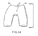
FIG. 14 is a distal view of an exemplary prosthesis;
FIG. 15 is a side view of the prosthesis of FIG. 14, illustrating the recessed patellar sulcus thereof as compared with a known prosthesis;
FIG. 16 is another side view of the prosthesis of FIG. 14, illustrating the reduced profile of the anterior condyles thereof as compared with a known prosthesis;
FIG. 17A is an A/P view of a known prosthesis having conventional sulcus tracking;
FIG. 17B is an A/P view of an exemplary prosthesis in accordance with the present invention having a more lateralized sulcus tracking;
FIG. 18 is a graph of A-A M/L vs. overall A/P for prostheses designed in accordance with the present invention as compared with several known prostheses; and
FIG. 19 is a graph of the ratio of (A-A M/L/overall A/P) vs. overall A/P for the prostheses of FIG. 18.
Corresponding reference characters indicate corresponding parts throughout the several views. The exemplifications set out herein illustrate exemplary embodiments of the invention, and such exemplifications are not to be construed as limiting the scope of the invention any manner.
DETAILED DESCRIPTION
As used herein, the following directional definitions apply. Anterior and posterior mean nearer the front or nearer the rear of the body, respectively. Thus, with respect to the prostheses described herein, anterior refers to that portion of the knee that is nearer the front of the body, when the leg is in an extended position. Proximal and distal mean nearer to or further from the root of a structure, respectively. For example, the distal femur is a part of the knee joint while the proximal femur is part of the hip joint. Finally, the adjectives medial and lateral mean nearer the sagittal plane or further from the sagittal plane, respectfully. The sagittal plane is an imaginary vertical plane through the middle of the body that divides the body into right and left halves.
Distal femoral knee prostheses made in accordance with the present invention are intended to be used to restore knee joint function in patients with severe pain and disability due, for example, to Rheumatoid arthritis, osteoarthritis, traumatic arthritis polyarthritis; collagen disorders, and/or avascular necrosis of the femoral condyle; post-traumatic loss of joint configuration, particularly when there is patellofemoral erosion, dysfunction or prior patellectomy; moderate valgus, varus, flexion deformities, or other conditions.
Referring initially to FIG. 1, a distal femoral prosthesis 50 for a TKR/TKA according to one embodiment of the present invention is shown, and generally includes an external articulating surface 52 and a bone contacting non-articulating internal surface 54. Articulating surface 52 includes an anterior articulating surface 56, a distal articulating surface 58, a lateral posterior condylar articulating surface 60, and a medial posterior condylar articulating surface 62. Prosthesis 50 may be made of any biocompatible material having the mechanical properties necessary to function as a human knee distal femoral prosthesis. Preferably, prosthesis 50 is made of titanium, titanium alloy, cobalt chrome alloy, stainless steel, or a ceramic. Referring additionally to FIG. 3, prosthesis 50 further includes patellar flange 64 including lateral and medial anterior condyles 66 and 68, respectively, as well as patellar sulcus 70 disposed between lateral and medial anterior condyles 66 and 68. Prosthesis also includes lateral and medial posterior condyles 72 and 74, respectively.
Referring to FIG. 1, the internal non-articulating portion 54 of prosthesis 50 is adapted to receive a resected distal femur. The surgical cuts made to the distal femur can be made by any means, in any sequence and in any configuration known to those of skill in the art of knee arthroplasty. Exemplary cut guides and processes for resecting the distal femur are shown and described in U.S. patent application Ser. No. 11/151,062, entitled ADJUSTABLE CUT GUIDE, filed on Jun. 13, 2005 and U.S. patent application Ser. No. 11/154,774, entitled MULTI-POSITIONABLE CUT GUIDE, filed on Jun. 16, 2005, assigned to the assignee of the present invention, the disclosures of which are expressly incorporated herein by reference.
In a preferred embodiment, prosthesis 50 comprises a plurality of chamfer surfaces corresponding to a plurality of chamfer surfaces or “box cuts” made in the distal femur. Non-articular surface 54 may comprise a porous metal surface or any surface likely to promote the growth of bone therein. Non-articular surface 54 of prosthesis 50 preferably comprises anterior non-articular surface 76, distal anterior non-articular surface 78, distal non-articular surface 80, two distal posterior non-articular surfaces 82, and two posterior non-articular surfaces 84.
Distal non-articular surface 80 is generally flat and adapted to receive the distal-most surface of the resected femur. Distal non-articular surface 80 comprises an anterior end and a posterior end. The anterior end of distal non-articular surface 80 abuts one end of distal anterior non-articular surface 78, which surface 78 also includes an anterior end and a posterior end. Surface 78 extends from surface 80 anteriorly and superiorly such that an obtuse angle is formed between surfaces 78 and 80. Anterior non-articular surface 76 extends superiorly from the anterior end of surface 78.
The posterior end of distal non-articular surface 80 abuts one end of each distal posterior non-articular surface 82, which surfaces 82 also include an anterior end and a posterior end. Surfaces 82 extend from surface 80 posteriorly and superiorly such that an obtuse angle is formed between surfaces 82 and 80. Posterior non-articular surfaces 84 extend superiorly from the posterior ends of surfaces 82, respectively.
As discussed in detail below, for many patients, particularly female patients, it is desirable to construct a set of prostheses 50 of varying size wherein the medial/lateral (“M/L”) width dimensions of the prostheses correspond more closely to the actual anatomical M/L width dimensions of the female femur and articulating surfaces. As described below, prostheses 50 addresses this concern by offering the surgeon a set of narrower prostheses in the M/L dimensions for a given set of anterior/posterior (“A/P”) prosthesis sizes which will allow the surgeon to use a prosthesis with both a correct A/P size and more accurate and optimized M/L dimensions to provide optimal prosthesis sizing and joint kinematics as compared to conventional prostheses.
In FIG. 3, the profile 86 of prosthesis 50 is superimposed upon profile 88 of a known prosthesis. As described in detail below, prosthesis 50 has a unique, substantially trapezoidal shape or profile 86 when viewed distally with a more pronounced narrowing of the M/L dimensions as compared to the shape or profile 88 of a known prosthesis starting, with reference to the resected femur, at the posterior distal facet and progressing anteriorly to the anterior distal facet. Referring to FIGS. 2 and 3, prosthesis 50 is shown and is characterized below with reference to the following directions: anterior “A”, posterior “P”, distal “D”, proximal “PR”, medial “M” and lateral “L”, as well as the following dimensions. Dimension “Posterior” is the M/L width at the widest point across the posterior condyles 72, 74 of prosthesis 50. Dimension “C-C” is the M/L width at the junction of the posterior distal facet and the distal plane, i.e., the M/L width along the intersection between distal non-articular surface 80 and distal posterior non-articular surfaces 82. Dimension “B-B” is the M/L width at the junction of the distal plane and the distal anterior facet, i.e., the M/L width along the intersection between distal non-articular surface 80 and distal anterior non-articular surface 78. Dimension “A-A” is the M/L width at the junction of the distal anterior facet and the posterior side of the anterior flange, i.e., the M/L width along the intersection of distal anterior non-articular surface 78 and anterior non-articular surface 76. Dimension “MB” is the M/L width at a “mid-box” point of prosthesis 50, i.e., along a line located on distal non-articular surface 80 substantially midway between Dimension C-C and Dimension B-B.
As described below, the profiles of a set of prostheses 50 can also be described in terms of an increasing narrowing of the M/L dimensions relative to known prostheses on a per size basis. It has been observed that, for given female femurs, for example, the M/L dimensions are sometimes smaller than those of known prostheses of the proper A/P dimension. This discrepancy is small on the smaller A/P size prostheses and increases as the A/P size increases. For example, referring to FIG. 5, a representative mid-box M/L vs. A/P dimensional relationship with respect to the actual human anatomy of distal femurs for males and females is shown. Representative female data is generally grouped together at lower values of mid-box M/L and representative male data is generally grouped together at higher values of mid-box M/L. Best fit lines for female and male data have been included on FIG. 5 to show the general trend of representative mid-box M/L dimensions. As may be seen from FIG. 5, there exists a clear distinction between the representative M/L dimension vs. the A/P dimension for a female distal femur as compared to a male distal femur. FIGS. 5A and 5B show exemplary anatomic overall A/P and mid-box M/L dimensions for a representative femur.
In FIG. 2, the overall A/P (“Overall A/P”) dimension is the distance between two lines perpendicular to distal non-articular surface 80 that pass through the most posterior point on the posterior face of exterior articulating surface 58 and through the most anterior point on the anterior face of exterior articulating surface 58, respectively. FIG. 2 also shows a dashed outline of a resected femur with prosthesis 50 positioned thereon.
As an exemplary comparison, the dimensions “Posterior”, “B-B”, “A-A”, and “Overall A/P” and the ratios of these values for conventional prostheses (“Conventional 1”, including five increasing sizes C through G) are compared with corresponding dimensions and ratios of a set of prostheses designed in accordance with the present invention (“Embodiment 1”, including five increasing sizes C through G). These values are presented in Table 1 below. Unless otherwise indicated, all numerical dimensional values presented herein are in millimeters (“mm”).
TABLE 1
Overall Overall
SIZE A/P “Post.” “B-B” “A-A” A/P “Post.” “B-B” “A-A”
Embodiment 1 Conventional 1
C 52.2 58.0 49.6 41.1 53.5 60.0 53.6 45.1
D 56.3 61.3 51.5 42.6 57.6 64.0 55.8 46.5
E 60.2 64.5 53.5 43.7 61.5 68.0 59.3 49.1
F 64.2 67.9 55.4 45.0 65.4 72.0 63.2 52.0
G 69.2 71.0 57.3 46.3 70.4 76.5 67.3 56.2
Embodiment 1 - Conventional 1 -
M/L/“Overall M/L/“Overall
A/P” RATIOS A/P” RATIOS
C 52.2 1.11 0.95 0.79 53.5 1.12 1.00 0.84
D 56.3 1.09 0.92 0.76 57.6 1.11 0.97 0.81
E 60.2 1.07 0.89 0.73 61.5 1.11 0.96 0.80
F 64.2 1.06 0.86 0.70 65.4 1.10 0.97 0.79
G 69.2 1.03 0.83 0.67 70.4 1.09 0.96 0.80
Table 2 below sets forth the results of a first order equation fit to data sets for several sets of prostheses including Conventional 1, Conventional 2 (which is similar to Conventional 1), Embodiment 1, Embodiment 2 (which is similar to Embodiment 1), as well as five other sets of known competitive prostheses, designated Competitive 1, Competitive 2, Competitive 3, Competitive 4, and Competitive 5. The data sets include Posterior M/L vs. Overall A/P and the Ratio (Posterior M/L vs. Overall A/P) vs. Overall A/P.
TABLE 2
Ratio (Posterior M/
Posterior M/L L/Overall A/P)
vs. Overall A/P vs. Overall A/P
Best fit regression line Best fit regression line
Equation Slope Equation Slope
Conventional 1 y = 0.9811x + 7.595 0.9811 y = −0.002x + 1.2277 −0.0020
Conventional 2 y = 0.9878x + 6.0634 0.9878 y = −0.0015x + 1.1798 −0.0015
Embodiment 1 y = 0.8036x + 16.228 0.8036 y = −0.0044x + 1.3431 −0.0044
Embodiment 2 y = 0.809x + 14.987 0.8090 y = −0.0039x + 1.2965 −0.0039
Competitive 1 y = 0.9411x + 7.1008 0.9411 y = −0.0016x + 1.1565 −0.0016
Competitive 2 y = 0.987x + 6.8225 0.9870 y = −0.0017x + 1.2015 −0.0017
Competitive 3 y = 0.976x + 5.7825 0.9760 y = −0.0013x + 1.1521 −0.0013
Competitive 4 y = 0.9757x + 6.6279 0.9757 y = −0.0016x + 1.1836 −0.0016
Competitive 5 y = 0.9336x + 11.318 0.9336 y = −0.0031x + 1.3111 −0.0031
From the data in Table 2, it may be seen that there is a difference in the slopes of the sets of prostheses of Embodiments 1 and 2 as compared to the slopes of the sets of the known prostheses. In particular, it may be seen from the data in Table 2 that the sets of prostheses of Embodiments 1 and 2 have a narrowing posterior M/L dimension with increasing A/P size, as indicated by slopes less than 0.93, for example, as opposed to a substantially parallel or one-to-one relationship between the posterior M/L dimension and the A/P dimension with increasing A/P size as in the sets of known prostheses, as indicated by slopes of 0.93 and above. Thus, in the sets of known prostheses, the posterior M/L dimension and the A/P dimension increase at substantially the same rate with increasing A/P size. Also, the slope of the ratio (posterior M/L/overall A/P) vs. overall A/P is less than −0.0032 for the sets of prostheses of Embodiments 1 and 2 while the corresponding slope for the known sets of prostheses is greater than −0.0032, indicating that the sets of prostheses of Embodiments 1 and 2 have an increasingly more pronounced narrowing of the posterior M/L dimension with increasing A/P size. In this manner, the sets of prostheses designed in accordance with the present invention offer a surgeon a unique combination of implant posterior M/L widths with varying A/P size for an overall system or set of prostheses, wherein such sets of prostheses are more anatomically optimized for the female anatomy as compared with the sets of known prostheses.
Table 3 below sets forth the results of a first order equation fit to data sets for several sets of prostheses including Conventional 1, Conventional 2 (which is similar to Conventional 1), Embodiment 1, Embodiment 2 (which is similar to Embodiment 1), as well as five other sets of known competitive prostheses, designated Competitive 1, Competitive 2, Competitive 3, Competitive 4, and Competitive 5. The data sets include B-B M/L vs. Overall A/P and the Ratio (B-B M/L vs. Overall A/P) vs. Overall A/P.
TABLE 3
Ratio (Anterior M/L
Anterior M/L “B-B” “B-B”/Overall A/P)
vs. Overall A/P vs. Overall A/P
Best fit regression line Best fit regression line
Equation Slope Equation Slope
Conventional 1 y = 0.834x + 8.3768 0.8340 y = −0.0023x + 1.112 −0.0023
Conventional 2 y = 0.8432x + 6.9003 0.8432 y = −0.0018x + 1.0681 −0.0018
Embodiment 1 y = 0.4626x + 25.012 0.4626 y = −0.0071x + 1.3173 −0.0071
Embodiment 2 y = 0.4626x + 25.012 0.4626 y = −0.0066x + 1.2797 −0.0066
Competitive 1 y = 0.9062x + 3.2306 0.9062 y = −0.0007x + 1.0017 −0.0007
Competitive 2 y = 0.8057x + 12.588 0.8057 y = −0.0031x + 1.2033 −0.0031
Competitive 3 y = 0.893x + 5.5381 0.8930 y = −0.0012x + 1.0578 −0.0012
Competitive 4 y = 1.0588x + 0.1731 1.0588 y = −0.0001x + 1.0697 −0.0001
Competitive 5 y = 0.7937x + 12.218 0.7937 y = −0.0036x + 1.217 −0.0036
From the data in Table 3, it may be seen that there is a significant difference in slope for the sets of prostheses of Embodiments 1 and 2 as compared with the slopes of the known sets of prostheses. The magnitudes of the anterior M/L “B-B” values for a given A/P dimension are more pronounced, i.e., the variance in width at dimension B-B, namely, an anterior width, over various A/P sizes between the sets of prostheses of Embodiments 1 and 2 and the known sets of prostheses is more dramatically pronounced. Specifically, sets of prostheses of Embodiments 1 and 2 have a narrowing anterior M/L dimension with increasing A/P size, as indicated by slopes less than 0.78, for example, as opposed to a substantially parallel or one-to-one relationship between the anterior M/L dimension and the A/P dimension with increasing A/P size as in the sets of known prostheses, as indicated by slopes of 0.78 and above. Thus, in the sets of known prostheses, the anterior M/L dimension and the A/P dimension increase at substantially the same rate with increasing A/P size. Also, the slope of the ratio (anterior M/L “B-B”/overall A/P) vs. overall A/P is greater than −0.0038 for the sets of prostheses of Embodiments 1 and 2, while the corresponding slope for the known sets of prostheses is less than −0.0038, indicating that the sets of prostheses of Embodiments 1 and 2 have increasingly more pronounced narrowing of the anterior M/L “B-B” dimension with increasing A/P size. In this manner, the prostheses designed in accordance with the present invention offer a surgeon a unique combination of implant M/L widths as an overall system of prostheses, wherein such sets of prostheses are more anatomically optimized for the female anatomy as compared with the sets of known prostheses.
As another exemplary comparison, the dimensions “Posterior”, “MB”, “B-B”, and “Overall A/P” for conventional prostheses (“Conventional 3”, “Conventional 4”, and “Conventional 5” including five increasing sizes C through G) are compared with corresponding dimensions of a set of prostheses designed in accordance with the present invention (“Embodiment 3”, “Embodiment 4”, and “Embodiment 5” including five increasing sizes C through G). In one embodiment, the values for Conventional 5 and Embodiment 5 may be average values of Conventionals 3 and 4 and Embodiments 3 and 4, respectively. These values are presented in Table 4 below.
TABLE 4
SIZE Overall A/P Posterior MB B-B Overall A/P Posterior MB B-B
Embodiment
4 Conventional 4
C 53.3 58.0 55.9 50.2 54.4 60.0 58.6 53.6
D 57.5 61.4 58.4 52.0 58.6 64.0 62.1 55.8
E 61.2 64.7 60.8 54.0 62.5 68.0 65.9 59.3
F 65.3 68.1 63.5 56.0 66.5 72.0 70.2 63.2
G 70.4 71.5 66.0 58.0 71.5 76.5 74.0 67.3
Embodiment 3 Conventional 3
C 52.3 58.0 55.9 50.2 53.5 60.0 58.6 53.6
D 56.4 61.4 58.4 52.0 57.6 64.0 62.0 55.7
E 60.2 64.7 60.8 54.0 61.5 68.0 65.9 59.3
F 64.2 68.1 63.5 56.0 65.5 72.0 70.2 63.2
G 69.4 71.5 66.0 58.0 70.5 76.5 74.0 67.2
Embodiment 5 Conventional 5
C 52.8 58.0 55.9 50.2 54.0 60.0 58.6 53.6
D 56.9 61.4 58.4 52.0 58.1 64.0 62.0 55.8
E 60.7 64.7 60.8 54.0 62.0 68.0 65.9 59.3
F 64.8 68.1 63.5 56.0 66.0 72.0 70.2 63.2
G 69.9 71.5 66.0 58.0 71.0 76.5 74.0 67.3
FIG. 6 is a graph of the dimension mid-box M/L vs. overall A/P for the following sets of prostheses, each in increasing sizes C through G: Conventional 5, Embodiment 5, as well as eight other sets of known competitive prostheses, designated Competitive 1, Competitive 2, Competitive 3, Competitive 4, Competitive 5, Competitive 6, Competitive 7, and Competitive 8.
FIG. 7 is a graph of the dimension B-B M/L vs. overall A/P for the following sets of prostheses, each in increasing sizes C through G: Conventional 5, Embodiment 5, as well as eight other sets of known competitive prostheses, designated Competitive 1, Competitive 2, Competitive 3, Competitive 4, Competitive 5, Competitive 6, Competitive 7, and Competitive 8.
FIG. 8 is a graph of the dimension Posterior M/L vs. overall A/P for the following sets of prostheses, each in increasing sizes C through G: Conventional 5, Embodiment 5, as well as eight other sets of known competitive prostheses, designated Competitive 1, Competitive 2, Competitive 3, Competitive 4, Competitive 5, Competitive 6, Competitive 7, and Competitive 8.
Table 5 below sets forth the results of a first order equation fit to each of the data sets shown in FIGS. 6, 7, and 8 as well as for the data sets of Embodiments 3 and 4 and Conventional 3 and 4 in Table 4.
TABLE 5
Posterior Mid-box
M/L vs. M/L vs. B-B M/L vs.
Overall A/P Overall A/P Overall A/P
Best Fit Best Fit Best Fit
Regression Regression Regression
Line Line Line
Implant Slope y-Intercept Slope y-Intercept Slope y-Intercept
Conventional
3 0.98 7.53 0.93 8.63 0.83 8.35
Conventional 4 0.98 6.82 0.93 8.02 0.83 7.66
Conventional 5 0.98 7.17 0.93 8.32 0.83 8.01
Embodiment 3 0.80 16.31 0.60 24.89 0.46 26.02
Embodiment 4 0.80 15.51 0.60 24.30 0.46 25.55
Embodiment 5 0.80 15.91 0.60 24.59 0.46 25.79
Competitive 1 1.06 1.27 1.01 3.36 0.94 1.61
Competitive 2 0.99 6.82 1.09 −1.10 0.80 12.80
Competitive 3 0.98 5.78 0.91 11.72 0.83 10.13
Competitive 4 0.98 6.63 1.02 3.40 1.06 0.17
Competitive 5 0.90 13.67 0.91 11.72 0.82 10.34
Competitive 6 1.06 0.61 1.08 −0.70 1.06 −4.03
Competitive 7 0.86 19.80 0.77 19.86 0.78 9.00
Competitive 8 0.91 −0.64 0.91 −1.64 0.91 −2.64
From the data in Table 5, it may be seen that there is a difference in the slopes of the sets of prostheses of Embodiments 3, 4, and 5 as compared to the slopes of the sets of the known prostheses. In particular, it may be seen from the data in Table 5 that the sets of prostheses of Embodiments 3, 4, and 5 have a narrowing posterior M/L dimension with increasing A/P size, as indicated by slopes less than approximately 0.85, for example, as opposed to a substantially parallel or one-to-one relationship between the posterior M/L dimension and the A/P dimension with increasing A/P size as in the sets of known prostheses, as indicated by slopes of 0.86 and above. In exemplary embodiments, the slope of posterior M/L dimension with increasing A/P size for prostheses 50 may be as small as approximately 0.50, 0.55, 0.60, or 0.65 or as large as approximately 0.85, 0.84, 0.83, 0.81, 0.80, 0.75, or 0.70. In an exemplary embodiment, the slope of posterior M/L dimension with increasing A/P size for prostheses 50 is approximately 0.80. Thus, the posterior M/L dimension for prostheses 50 increases at a lesser rate than the corresponding overall A/P dimension. In contrast, in the sets of known prostheses, the posterior M/L dimension and the A/P dimension increase at substantially the same rate with increasing A/P size. In this manner, the sets of prostheses designed in accordance with the present invention offer a surgeon a unique combination of implant posterior M/L widths with varying A/P size for an overall system or set of prostheses, wherein such sets of prostheses are more anatomically optimized for the female anatomy as compared with the sets of known prostheses.
Furthermore, from the data in Table 5, it may be seen that there is a significant difference in slope for the sets of prostheses of Embodiments 3, 4, and 5 as compared with the slopes of the known sets of prostheses when looking at the B-B and MB dimensions. The magnitudes of the B-B values and MB values for a given A/P dimension are more pronounced, i.e., the variance in width at dimension B-B or MB over various A/P sizes between the sets of prostheses of Embodiments 3, 4, and 5 and the known sets of prostheses is more dramatically pronounced.
Specifically, sets of prostheses of Embodiments 3, 4, and 5 have a narrowing B-B M/L dimension with increasing A/P size, as indicated by slopes less than approximately 0.77, for example, as opposed to a substantially parallel or one-to-one relationship between the B-B M/L dimension and the A/P dimension with increasing A/P size as in the sets of known prostheses, as indicated by slopes of 0.78 and above. In exemplary embodiments, the slope of the B-B M/L dimension with increasing A/P size for prostheses 50 may be as small as approximately 0.30, 0.35, 0.40, or 0.45 or as large as 0.77, 0.76, 0.75, 0.74, 0.72, 0.70, 0.65, 0.60, or 0.50. In an exemplary embodiment, the slope is of the B-B M/L dimension with increasing A/P size for prostheses 50 is approximately 0.46. Thus, the B-B M/L dimension for prostheses 50 increases at a lesser rate than the corresponding overall A/P dimension. In contrast, in the sets of known prostheses, the B-B M/L dimension and the A/P dimension increase at substantially the same rate with increasing A/P size.
Furthermore, sets of prostheses of Embodiments 3, 4, and 5 have a narrowing MB M/L dimension with increasing A/P size, as indicated by slopes less than 0.76, for example, as opposed to a substantially parallel or one-to-one relationship between the MB M/L dimension and the A/P dimension with increasing A/P size as in the sets of known prostheses, as indicated by slopes of 0.77 and above. In exemplary embodiments, the slope of the MB M/L dimension with increasing A/P size for prostheses 50 may be as small as approximately 0.40, 0.45, 0.50, 0.55, or 0.57 or as large as approximately 0.76, 0.75, 0.74 0.73, 0.72, 0.71, 0.70, 0.65, or 0.60. In an exemplary embodiment, the slope of the MB M/L dimension with increasing A/P size for prostheses 50 is approximately 0.60. Thus, the MB M/L dimension for prostheses 50 increases at a lesser rate than the corresponding overall A/P dimension. In contrast, in the sets of known prostheses, the MB M/L dimension and the A/P dimension increase at substantially the same rate with increasing A/P size.
In this manner, the prostheses designed in accordance with the present invention offer a surgeon a unique combination of implant M/L widths as an overall system of prostheses, wherein such sets of prostheses are more anatomically optimized for the female anatomy as compared with the sets of known prostheses.
Referring again to FIG. 6, the range of values for Embodiment 5 generally falls within the lines of a conceptual boundary, such as a parallelogram, as shown in solid dashed lines. Clearly, no other known prostheses have MB M/L dimensions that fall within this range of values for the MB M/L dimensions and corresponding Overall A/P dimensions. The parallelogram is essentially defined by four points defined by coordinates given by (Overall A/P dimension, MB Dimension): A first point or upper left corner (“First Point”)—(52.0, 55.0); A second point or lower left corner (“Second Point”)—(52.0, 47.0); A third point or upper right corner (“Third Point”)—(77.0, 78.5); and a fourth point or lower right corner (“Fourth Point”)—(77.0, 70.0). Thus, the upper boundary of the parallelogram defined by First Point and Third Point may be given by the equation MB M/L=0.94*Overall A/P+6.12 and the lower boundary defined by Second Point and Fourth Point may be given by the equation MB M/L=0.92*Overall A/P−0.84.
As set forth in Table 6 below, the Overall A/P dimensions and the ratios of the dimensions “Posterior”, “MB”, and “B-B” vs. “Overall A/P” are given for Embodiments 3, 4, and 5 as well as for conventional prostheses Conventional 3, 4, and 5.
TABLE 6
Ratio Ratio Ratio Ratio Ratio Ratio
(Posterior (MB (B-B (Posterior (MB (B-B
M/L/ M/L/ M/L/ M/L/ M/L/ M/L/
Overall Overall Overall Overall Overall Overall Overall
SIZE A/P A/P) A/P) A/P) Overall A/P A/P) A/P) A/P)
Embodiment 4 Conventional 4
C 53.3 1.09 1.05 0.94 54.4 1.10 1.08 0.98
D 57.5 1.07 1.02 0.91 58.6 1.09 1.06 0.95
E 61.2 1.06 0.99 0.88 62.5 1.09 1.05 0.95
F 65.3 1.04 0.97 0.86 66.5 1.08 1.06 0.95
G 70.4 1.02 0.94 0.82 71.5 1.07 1.04 0.94
Embodiment 3 Conventional 3
C 52.3 1.11 1.07 0.96 53.5 1.12 1.09 1.00
D 56.4 1.09 1.04 0.92 57.6 1.11 1.08 0.97
E 60.2 1.08 1.01 0.90 61.5 1.11 1.07 0.96
F 64.2 1.06 0.99 0.87 65.5 1.10 1.07 0.97
G 69.4 1.03 0.95 0.84 70.5 1.09 1.05 0.95
Embodiment 5 Conventional 5
C 52.8 1.10 1.06 0.95 54.0 1.11 1.09 0.99
D 56.9 1.08 1.03 0.91 58.1 1.10 1.07 0.96
E 60.7 1.07 1.00 0.89 62.0 1.10 1.06 0.96
F 64.8 1.05 0.98 0.86 66.0 1.09 1.06 0.96
G 69.9 1.02 0.94 0.83 71.0 1.08 1.04 0.95
FIG. 9 is a graph of the ratio of (MB M/L/Overall A/P) vs. Overall A/P for the prostheses described above with respect to FIG. 6. FIG. 10 is a graph of the ratio of (B-B M/L/Overall A/P) vs. Overall A/P for the prostheses described above with respect to FIG. 7. FIG. 11 is a graph of the ratio of (Posterior M/L/Overall A/P) vs. Overall A/P for the prostheses described above with respect to FIG. 8.
Table 7 below sets forth the results of a first order equation fit to each of the data sets shown in FIGS. 9, 10, and 11 as well as for the data sets of Embodiments 3 and 4 and Conventional 3 and 4 in Table 6.
TABLE 7
Ratio Ratio Ratio
(Posterior M/L (Mid-box M/L (B-B M/L
vs. Overall vs. Overall vs. Overall
A/p) vs. A/P) vs. A/P) vs.
Overall A/P Overall A/P Overall A/P
Best Fit Best Fit Best Fit
Regression Regression Regression
Line Line Line
Implant Slope y-Intercept Slope y-Intercept Slope y-Intercept
Conventional
3 −0.0020 1.23 −0.0023 1.21 −0.0023 1.11
Conventional 4 −0.0017 1.20 −0.0020 1.18 −0.0020 1.08
Conventional 5 −0.0018 1.21 −0.0021 1.20 −0.0022 1.10
Embodiment 3 −0.0044 1.34 −0.0068 1.42 −0.0071 1.33
Embodiment 4 −0.0041 1.31 −0.0064 1.39 −0.0068 1.30
Embodiment 5 −0.0042 1.32 −0.0066 1.41 −0.0069 1.31
Competitive 1 −0.0003 1.10 −0.0008 1.11 −0.0004 0.99
Competitive 2 −0.0017 1.20 0.0003 1.06 −0.0032 1.21
Competitive 3 −0.0013 1.15 −0.0003 1.09 −0.0024 1.14
Competitive 4 −0.0016 1.18 −0.0009 1.13 −0.0001 1.07
Competitive 5 −0.0032 1.32 −0.0032 1.31 −0.0025 1.15
Competitive 6 −0.0001 1.08 0.0001 1.06 0.0010 0.94
Competitive 7 −0.0053 1.51 −0.0054 1.43 −0.0024 1.08
Competitive 8 0.0001 0.89 0.0004 0.86 0.0006 0.83
From the data in Table 7 it may be seen that there is a difference in the slopes of the sets of prostheses of Embodiments 3, 4, and 5 as compared to the slopes of the sets of the known prostheses. In particular, it may be seen from the data in Table 7 that the sets of prostheses of Embodiments 3, 4, and 5 have a narrowing posterior M/L dimension with increasing A/P size, as indicated by the slope of the ratio (posterior M/L/overall A/P) vs. overall A/P being less than −0.0032 for the sets of prostheses of Embodiments 3, 4, and 5 while the corresponding slope for the known sets of prostheses is greater than or equal to −0.0032, except for the Competitive 7 prosthesis, indicating that the sets of prostheses of Embodiments 3, 4, and 5 have an increasingly more pronounced narrowing of the posterior M/L dimension with increasing A/P size. In this manner, the sets of prostheses designed in accordance with the present invention offer a surgeon a unique combination of implant posterior M/L widths with varying A/P size for an overall system or set of prostheses, wherein such sets of prostheses are more anatomically optimized for the female anatomy as compared with the sets of known prostheses.
Furthermore, it may be seen that there is a significant difference in slope for the sets of prostheses of Embodiments 3, 4, and 5 as compared with the slopes of the known sets of prostheses when looking at the MB and B-B M/L dimensions. The magnitudes of the anterior M/L “B-B” values for a given A/P dimension are more pronounced, i.e., the variance in width at dimension B-B, namely, an anterior width, over various A/P sizes between the sets of prostheses of Embodiments 3, 4, and 5 and the known sets of prostheses is more dramatically pronounced. Specifically, the slope of the ratio (B-B M/L/overall A/P) vs. overall A/P is less than −0.0032 for the sets of prostheses of Embodiments 3, 4, and 5, while the corresponding slope for the known sets of prostheses is greater than or equal to −0.0032, indicating that the sets of prostheses of Embodiments 3, 4, and 5 have increasingly more pronounced narrowing of the B-B M/L dimension with increasing A/P size.
Furthermore, the slope of the ratio (MB M/L/Overall A/P) vs. Overall A/P is less than −0.0054 for the sets of prostheses of Embodiments 3, 4, and 5, while the corresponding slope for the known sets of prostheses is greater than or equal to −0.0054, indicating that the sets of prostheses of Embodiments 3, 4, and 5 have increasingly more pronounced narrowing of the B-B M/L dimension with increasing A/P size. Prostheses 50 may have slope values for the ratios of MB M/L/Overall A/P vs. Overall A/P with increasing A/P size which may be as small as −0.0075, −0.0072, −0.0069, −0.0066, or −0.0063 or as large as −0.0055, −0.0057, −0.0059, or −0.0061. In this manner, the prostheses designed in accordance with the present invention offer a surgeon a unique combination of implant M/L widths as an overall system of prostheses, wherein such sets of prostheses are more anatomically optimized for the female anatomy as compared with the sets of known prostheses.
Referring again to FIG. 9, the range of values for Embodiment 5 generally falls within the lines of a conceptual boundary, such as a four-sided polygon, as shown in solid dashed lines. Clearly, no other known prostheses have MB M/L/Overall A/P ratios that fall within this range of values for the MB M/L/Overall A/P ratios and corresponding Overall A/P dimensions. The polygon is essentially defined by four points defined by coordinates given by (Overall A/P dimension, MB M/L/Overall A/P ratio): A first point or upper left corner (“First Point”)—(52.0, 1.06); A second point or lower left corner (“Second Point”)—(52.0, 0.90); A third point or upper right corner (“Third Point”)—(77.0, 1.02); and a fourth point or lower right corner (“Fourth Point”)—(77.0, 0.91). Thus, the upper boundary of the parallelogram defined by First Point and Third Point may be given by the equation MB M/L/Overall A/P Ratio=−0.0015*Overall A/P+1.14 and the lower boundary defined by Second Point and Fourth Point may be given by the equation MB M/L/Overall A/P Ratio=0.0002*Overall A/P+0.89.
As another exemplary comparison, the dimensions “A-A” and “Overall A/P” for conventional prostheses (“Conventional 3”, “Conventional 4”, and “Conventional 5” including five increasing sizes C through G) are compared with corresponding dimensions of a set of prostheses designed in accordance with the present invention (“Embodiment 3”, “Embodiment 4”, and “Embodiment 5” including five increasing sizes C through G). In one embodiment, the values for Conventional 5 and Embodiment 5 may be average values of Conventionals 3 and 4 and Embodiments 3 and 4, respectively. These values are presented in Table 8 below.
TABLE 8
SIZE Overall A/P A-A Overall A/P A-A
Embodiment
4 Conventional 4
C 53.3 41.0 54.4 45.0
D 57.5 42.6 58.6 46.3
E 61.2 43.6 62.5 48.9
F 65.3 44.9 66.5 51.7
G 70.4 46.1 71.5 56.0
Embodiment 3 Conventional 3
C 52.3 41.0 53.5 45.0
D 56.4 42.6 57.6 46.4
E 60.2 43.6 61.5 48.5
F 64.2 44.9 65.5 51.6
G 69.4 46.1 70.5 55.7
Embodiment 5 Conventional 5
C 52.8 41.0 54.0 45.0
D 56.9 42.6 58.1 46.3
E 60.7 43.6 62.0 48.7
F 64.8 44.9 66.0 51.7
G 69.9 46.1 71.0 55.8
FIG. 18 is a graph of the dimension A-A M/L vs. overall A/P for the following sets of prostheses, each in increasing sizes C through G: Conventional 5, Embodiment 5, as well as eight other sets of known competitive prostheses, designated Competitive 1, Competitive 2, Competitive 3, Competitive 4, Competitive 5, Competitive 6, Competitive 7, and Competitive 8.
Table 9 below sets forth the results of a first order equation fit to the data sets shown in FIG. 18 as well as for the data sets of Embodiments 3 and 4 and Conventional 3 and 4 in Table 8.
TABLE 9
A-A M/L
vs. Overall
A/P Best Fit
Regression Line
Implant Slope y-Intercept
Conventional
3 0.64 9.66
Conventional 4 0.65 8.59
Conventional 5 0.65 9.13
Embodiment 3 0.30 25.78
Embodiment 4 0.30 25.47
Embodiment 5 0.30 25.63
Competitive 1 0.54 13.20
Competitive 2 0.46 19.33
Competitive 3 0.68 9.93
Competitive 4 0.76 6.05
Competitive 5 0.28 30.74
Competitive 6 0.86 2.98
Competitive 7 0.68 6.54
Competitive 8 0.57 13.19
From the data in Table 9, it may be seen that there is a difference in the slopes of the sets of prostheses of Embodiments 3, 4, and 5 as compared to the slopes of the sets of the known prostheses. In particular, it may be seen from the data in Table 9 that the sets of prostheses of Embodiments 3, 4, and 5 have a narrowing A-A M/L dimension with increasing A/P size, as indicated by slopes less than approximately 0.46, except for Competitive 5, for example, as opposed to a substantially parallel or one-to-one relationship between the posterior M/L dimension and the A/P dimension with increasing A/P size as in the sets of known prostheses, as indicated by slopes greater than or equal 0.46. In an exemplary embodiment, the slope of A-A M/L dimension with increasing A/P size for prostheses 50 is approximately 0.30.
As set forth in Table 10 below, the Overall A/P dimensions and the ratios of the dimension “A-A” vs. “Overall A/P” are given for Embodiments 3, 4, and 5 as well as for conventional prostheses Conventional 3, 4, and 5.
TABLE 10
Ratio (A-A M/L/ Ratio (A-A M/L/
SIZE Overall A/P Overall A/P) Overall A/P Overall A/P)
Embodiment 4 Conventional 4
C 53.3 0.77 54.4 0.83
D 57.5 0.74 58.6 0.79
E 61.2 0.71 62.5 0.78
F 65.3 0.69 66.5 0.78
G 70.4 0.66 71.5 0.78
Embodiment 3 Conventional 3
C 52.3 0.78 53.5 0.84
D 56.4 0.76 57.6 0.81
E 60.2 0.72 61.5 0.79
F 64.2 0.70 65.5 0.79
G 69.4 0.66 70.5 0.79
Embodiment 5 Conventional 5
C 52.8 0.78 54.0 0.83
D 56.9 0.75 58.1 0.80
E 60.7 0.72 62.0 0.78
F 64.8 0.69 66.0 0.78
G 69.9 0.66 71.0 0.79
FIG. 19 is a graph of the ratio of (A-A M/L/Overall A/P) vs. Overall A/P for the prostheses described above with respect to FIG. 18.
Table 11 below sets forth the results of a first order equation fit to the data sets shown in FIG. 19 as well as for the data sets of Embodiments 3 and 4 and Conventional 3 and 4 in Table 10.
TABLE 11
Ratio (A-A M/L vs. Overall A/P)
vs. Overall A/P Best Fit
Regression Line
Implant Slope y-Intercept
Conventional
3 −0.0027 0.97
Conventional 4 −0.0023 0.94
Conventional 5 −0.0025 0.95
Embodiment 3 −0.0071 1.15
Embodiment 4 −0.0067 1.13
Embodiment 5 −0.0069 1.14
Competitive 1 −0.0031 0.94
Competitive 2 −0.0049 1.08
Competitive 3 −0.0024 0.99
Competitive 4 −0.0016 0.96
Competitive 5 −0.0073 1.24
Competitive 6 0.0007 0.77
Competitive 7 −0.0019 0.90
Competitive 8 −0.0033 0.99
From the data in Table 11 it may be seen that there is a difference in the slopes of the sets of prostheses of Embodiments 3, 4, and 5 as compared to the slopes of the sets of the known prostheses. In particular, it may be seen from the data in Table 7 that the sets of prostheses of Embodiments 3, 4, and 5 have a narrowing A-A M/L dimension with increasing A/P size, as indicated by the slope of the ratio (A-A M/L/overall A/P) vs. overall A/P being less than −0.0049, for the sets of prostheses of Embodiments 3, 4, and 5 while the corresponding slope for the known sets of prostheses is greater than or equal to −0.0049, except for the Competitive 5 prosthesis, indicating that the sets of prostheses of Embodiments 3, 4, and 5 have an increasingly more pronounced narrowing of the A-A M/L dimension with increasing A/P size. In this manner, the sets of prostheses designed in accordance with the present invention offer a surgeon a unique combination of implant A-A M/L widths with varying A/P size for an overall system or set of prostheses, wherein such sets of prostheses are more anatomically optimized for the female anatomy as compared with the sets of known prostheses.
Referring again to FIG. 18, the range of values for Embodiment 5 generally falls below the line of a conceptual boundary. The boundary may be defined by two points defined by coordinates given by (Overall A/P dimension, A-A M/L dimension): a First Point (52.0, 40.3) and a Second Point (77.0, 51.8). Thus, the boundary defines a line given by the following equation: A-A M/L=0.46*Overall A/P+16.38.
Referring again to FIG. 19, the range of values for Embodiment 5 generally falls below the line of a conceptual boundary. The boundary may be defined by two points defined by coordinates given by (Overall A/P dimension, A-A M/L/Overall A/P ratio): a First Point (52.0, 0.78) and a Second Point (77.0, 0.67). Thus, the boundary defines a line given by the following equation: A-A M/L/Overall A/P=−0.0041*Overall A/P+0.99.
Another way of characterizing the design of the present prostheses is by distal taper angle, “DT”. As used herein and referring to FIG. 12, in which the profile 86 of prosthesis 50 is superimposed upon profile 88 of a known prosthesis, the distal taper angle “DT” is the angle between two lines on opposite sides of the prosthesis each connecting a point 90 on the edge of the anterior distal chamfer, i.e., along dimension “B-B” and a point 92 on the edge of the posterior distal chamfer, i.e., along dimension “C-C”. In FIG. 12, distal taper angles DT1 and DT2 for prosthesis 50 and for a known prosthesis are illustrated, respectively. It may be seen from FIG. 12 that the distal taper angle DT1 for prosthesis 50 is greater than the distal taper angle DT2 for the known prosthesis.
FIG. 13 is a chart of distal taper angle vs. overall A/P for several of the prostheses described above. As before, a first order curve fit was applied to the data in FIG. 13 and the results are set forth below in Table 12.
TABLE 12
Distal Taper Angle
vs. Overall A/P
Best fit regression line
Equation Slope
Conventional 3 y = 0.01x + 18.72 0.01
Conventional 4 y = 0.01x + 18.79 0.01
Conventional 5 y = 0.01x + 17.75 0.01
Embodiment 3 y = 0.28x + 7.10 0.28
Embodiment 4 y = 0.28x + 6.80 0.28
Embodiment 5 y = 0.28x + 6.95 0.28
Competitive 1 y = −0.15x + 24.81 −0.15
Competitive 2 y = 0.20x + 3.04 0.20
Competitive 3 y = −0.08x + 19.43 −0.08
Competitive 4 y = −0.24x + 18.77 −0.24
Competitive 5 y = −0.18x + 33.07 −0.18
Competitive 6 y = −0.19x + 21.99 −0.19
Competitive 7 y = −0.48x + 67.89 −0.48
Competitive 8 y = −0.06x + 9.37 −0.06
As may be seen from the data in Table 12, the ratio between distal taper angle and overall A/P of the prostheses of Embodiments 3-5 differs from the known prostheses. In particular, the foregoing data indicates that prostheses of Embodiments 3-5 have a more pronounced and consistent increase in distal taper angle with increasing A/P size, as evidenced by a slope of greater than 0.20. Additionally, as may be seen from FIG. 13, the set of prostheses of Embodiment 5 has greater distal taper angles throughout the range of sizes of the prostheses than the known sets of prostheses with positive slopes as set forth in Table 12. Further, the distal taper angle curve for the set of prostheses of Embodiment 5 has a consistent upward slope as opposed to the randomized “see-saw” curves or flattened curves of the known sets of prostheses, indicating a more precise, parallel or substantial one-to-one relationship between distal taper angle and overall A/P with increasing A/P size for the set of prostheses of Embodiment 5. In exemplary embodiments, the slope of the distal taper angle with increasing A/P size for prostheses 50 may be as small as approximately 0.21, 0.22, 0.23, 0.24, 0.25, 0.26, 0.27, or 0.30 or as large as approximately 0.42, 0.39, 0.36, or 0.33. In an exemplary embodiment, the slope of the distal taper angle with increasing A/P size for prostheses 50 is approximately 0.28.
As shown in FIG. 13, the range of values for Embodiment 5 generally fall within the lines of a conceptual boundary, such as a four-sided polygon, as shown in solid dashed lines. Clearly, no other known prostheses have distal taper angle values that fall within this range of values for the distal taper angle and corresponding Overall A/P dimensions. The four-sided polygon is essentially defined by four points defined by coordinates given by (Overall A/P dimension, Distal Taper Angle): An upper left corner (“1B”)—(52.0, 27.0°); A lower left corner (“4”)—(58.0, 22.5°); An upper right corner (“2”)—(77.0, 32.0°); and a lower right corner (“3”)—(77.0, 26.0°). Alternatively, the upper left corner may be at coordinates (52.0, 34.0°) (“1A”). Alternatively, points 1A, 1B, 2, 3, and 4 define a five-sided polygon which defines the conceptual boundary. The distal taper angles for Embodiment 5 may be approximately equal to or greater than 21°. The values of distal taper angles for prostheses 50 may be as small as approximately 21°, 22°, 23°, 25°, or 27, as large as approximately 35°, 33°, 31°, or 29°.
Referring again to FIG. 8, the sets of prostheses may be grouped into a standard aspect ratio category and a non-standard aspect ratio category. As used herein, the term “standard aspect ratio” describes a set of prostheses which, for overall A/P values ranging from approximately 52.0 mm to 77.0 mm, have corresponding posterior M/L dimensions which generally fall between an Upper Boundary and a Lower Boundary. The Upper Boundary and Lower Boundary may be defined by lines having points defined by coordinates given by (Overall A/P dimension, Posterior M/L dimension). The Upper Boundary may be defined by a line connecting a first or lower left point (“First Upper Point”)—(52.0, 59.0) and a second or upper right point (“Second Upper Point”)—(77.0, 83.5). The Lower Boundary may be defined by three exemplary boundaries. In one exemplary embodiment, Lower Boundary 1 may be defined by a line connecting a first or lower left point (“First Lower Point 1”)—(52.0, 51.0) and a second or upper right point (“Second Lower Point 1”)—(77.0, 73.0). In another exemplary embodiment, Lower Boundary 2 may be defined by a line connecting a first or lower left point (“First Lower Point 2”)—(52.0, 53.0) and a second or upper right point (“Second Lower Point 2”)—(77.0, 75.0). In yet another exemplary embodiment, Lower Boundary 3 may be defined by a line connecting a first or lower left point (“First Lower Point 3”)—(52.0, 55.0) and a second or upper right point (“Second Lower Point 3”)—(77.0, 77.0). For prostheses having overall A/P values ranging from approximately 52.0 mm to 77.0 mm, the following equations may define the Upper and Lower Boundaries: the Upper Boundary line may be defined by the following equation: Posterior M/L=0.98*Overall A/P+8.04; the Lower Boundary 1 line may be defined by the following equation: Posterior M/L=0.88*Overall A/P+5.24; the Lower Boundary 2 line may be defined by the following equation: Posterior M/L=0.88*Overall A/P+7.24; and the Lower Boundary 3 line may be defined by the following equation: Posterior M/L=0.88*Overall A/P+9.24.
Referring again to FIG. 11, the Upper Boundary and Lower Boundary described above which are used to define the standard aspect ratio category for sets of prostheses may also be used with the posterior M/L/Overall A/P ratio for overall A/P values ranging from approximately 52.0 mm to 77.0 mm. The Upper Boundary and Lower Boundary may be defined by lines having points defined by coordinates given by (Overall A/P dimension, Posterior M/L/Overall A/P Ratio). The Upper Boundary may be defined by a line connecting a first or lower left point (“First Upper Point”)—(52.0, 1.13) and a second or upper right point (“Second Upper Point”)—(77.0, 1.08). The Lower Boundary may be defined by three exemplary boundaries. Lower Boundary 1 may be defined by a line connecting a first or lower left point (“First Lower Point 1”)—(52.0, 0.98) and a second or upper right point (“Second Lower Point 1”)—(77.0, 0.95). Lower Boundary 2 may be defined by a line connecting a first or lower left point (“First Lower Point 2”)—(52.0, 1.02) and a second or upper right point (“Second Lower Point 2”)—(77.0, 0.97). Lower Boundary 3 may be defined by a line connecting a first or lower left point (“First Lower Point 3”)—(52.0, 1.06) and a second or upper right point (“Second Lower Point 3”)—(77.0, 1.00). For prostheses having overall A/P values ranging from approximately 52.0 mm to 77.0 mm, the following equations may define the Upper and Lower Boundaries: the Upper Boundary line may be defined by the following equation: Posterior M/L/Overall A/P=−0.0020*Overall A/P+1.24; the Lower Boundary 1 line may be defined by the following equation: Posterior M/L/Overall A/P=−0.0013*Overall A/P+1.05; the Lower Boundary 2 line may be defined by the following equation: Posterior M/L/Overall A/P=−0.0018*Overall A/P+1.11; and the Lower Boundary 3 line may be defined by the following equation: Posterior M/L/Overall A/P=−0.0023*Overall A/P+1.18.
Referring to FIGS. 8 and 11 and applying the foregoing definition of standard aspect ratio, it may be seen that the prostheses described by Competitive 5, Competitive 7, and Competitive 8 fall within the non-standard aspect ratio category.
Referring again to FIG. 13, Embodiment 5 has a distal taper angle greater than or equal to 21°. In contrast, all other standard aspect ratio prostheses have a distal taper angle less than 21°.
Referring again to FIG. 6, Embodiment 5 has MB M/L dimensions below the boundary defined by a line connecting the First Point (52.0, 55.0) and the Third Point (77.0, 78.5). Thus, for the range of Overall A/P values between 52.0 and 77.0, Embodiment 5 has MB M/L dimensions which fall below the line given by the following equation: MB M/L=0.94*Overall A/P+6.12. In contrast, all other standard aspect ratio prostheses have MB M/L dimensions which fall above the line given by the foregoing equation.
Referring again to FIG. 9, Embodiment 5 has MB M/L/Overall A/P ratios below the boundary defined by a line connecting the First Point (52.0, 1.06) and the Third Point (77.0, 1.02). Thus, for the range of Overall A/P values between 52.0 and 77.0, Embodiment 5 has MB M/L/Overall A/P ratios which fall below the line given by the following equation: MB M/L/Overall A/P=−0.0015*Overall A/P+1.14. In contrast, all other standard aspect ratio prostheses have MB M/L/Overall A/P ratios which fall above the line given by the foregoing equation.
Referring again to FIG. 7, Embodiment 5 has B-B M/L dimensions below the boundary defined by a line connecting the First Point (52.0, 50.0) and the Second Point (77.0, 70.5). Thus, for the range of Overall A/P values between 52.0 and 77.0, Embodiment 5 has B-B M/L dimensions which fall below the line given by the following equation: B-B M/L=0.82*Overall A/P+7.36. In contrast, all other standard aspect ratio prostheses have B-B M/L dimensions which fall above the line given by the foregoing equation.
Referring again to FIG. 10, Embodiment 5 has B-B M/L/Overall A/P ratios below the boundary defined by a line connecting the First Point (52.0, 0.96) and the Second Point (77.0, 0.92). Thus, for the range of Overall A/P values between 52.0 and 77.0, Embodiment 5 has B-B M/L/Overall A/P ratios which fall below the line given by the following equation: B-B M/L/Overall A/P=−0.0018*Overall A/P+1.06. In contrast, all other standard aspect ratio prostheses have B-B M/L/Overall A/P ratios which fall above the line given by the foregoing equation.
Referring again to FIG. 18, Embodiment 5 has A-A M/L dimensions below the boundary defined by a line connecting the Third Point (52.0, 40.1) and the Fourth Point (77.0, 53.5). Thus, for the range of Overall A/P values between 52.0 and 77.0, Embodiment 5 has A-A M/L dimensions which fall below the line given by the following equation: A-A M/L=0.54*Overall A/P+12.23. In contrast, all other standard aspect ratio prostheses have A-A M/L dimensions which fall above the line given by the foregoing equation.
Referring again to FIG. 19, Embodiment 5 has A-A M/L/Overall A/P ratios below the boundary defined by a line connecting the Third Point (52.0, 0.77) and the Fourth Point (77.0, 0.69). Thus, for the range of Overall A/P values between 52.0 and 77.0, Embodiment 5 has A-A M/L/Overall A/P ratios which fall below the line given by the following equation: A-A M/L/Overall A/P=−0.0031*Overall A/P+0.93. In contrast, all other standard aspect ratio prostheses have A-A M/L/Overall A/P ratios which fall above the line given by the foregoing equation.
Referring again to Table 5, Embodiments 3-5 have slopes of Posterior M/L dimension with increasing A/P size which are less than 0.98. Prostheses 50 may have slope values for the Posterior M/L dimension with increasing A/P size which may be as small as approximately 0.50, 0.55, 0.60, or 0.65 or as large as approximately 0.96, 0.95, 0.94, 0.91, 0.88, 0.85, 0.84, 0.83, 0.81, 0.80, 0.75, or 0.70. In contrast, all other standard aspect ratio prostheses have slopes of Posterior M/L dimension with increasing A/P size which are greater than or equal to 0.98.
Referring still to Table 5, Embodiments 3-5 have slopes of MB M/L dimension with increasing A/P size which are less than 0.91. Prostheses 50 may have slope values for the MB M/L dimension with increasing A/P size which may be as small as approximately 0.40, 0.45, 0.50, 0.55, or 0.57 or as large as approximately 0.90, 0.89, 0.87, 0.84, 0.81, 0.79, 0.76, 0.75, 0.74, 0.73, 0.72, 0.71, 0.70, 0.65, or 0.60. In contrast, all other standard aspect ratio prostheses have slopes of MB M/L dimension with increasing A/P size which are greater than or equal to 0.91.
Referring again to Table 5, Embodiments 3-5 have slopes of B-B M/L dimension with increasing A/P size which are less than 0.80. Prostheses 50 may have slope values for the B-B M/L dimension with increasing A/P size which may be as small as approximately 0.30, 0.35, 0.40, or 0.45 or as large as 0.79, 0.78, 0.77, 0.76, 0.75, 0.74, 0.72, 0.70, 0.65, 0.60, or 0.50. In contrast, all other standard aspect ratio prostheses have slopes of B-B M/L dimension with increasing A/P size which are greater than or equal to 0.80.
Referring to Table 9, Embodiments 3-5 have slopes of A-A M/L dimension with increasing A/P size which are less than 0.46. Prostheses 50 may have slope values for the A-A M/L dimension with increasing A/P size which may be as small as 0.15, 0.20, 0.25, or 0.30 or as large as 0.45, 0.44, 0.42, 0.40, 0.37, 0.34, or 0.31. In contrast, all other standard aspect ratio prostheses have slopes of A-A M/L dimension with increasing A/P size which are greater than or equal to 0.46.
Referring to Table 7, Embodiments 3-5 have slopes for the ratios of Posterior M/L/Overall A/P vs. Overall A/P with increasing A/P size which are less than −0.0020. Prostheses 50 may have slope values for the ratios of Posterior M/L/Overall A/P vs. Overall A/P with increasing A/P size which may be as small as −0.0060, −0.0055, −0.0050, −0.0045, −0.0040 or as large as −0.0021, −0.0022, −0.0025, −0.0030, or −0.0035. In contrast, all other standard aspect ratio prostheses have slopes for the ratios of Posterior M/L/Overall A/P vs. Overall A/P with increasing A/P size which are greater than or equal to −0.0020.
Referring again to Table 7, Embodiments 3-5 have slopes for the ratios of MB M/L/Overall A/P vs. Overall A/P with increasing A/P size which are less than −0.0023. Prostheses 50 may have slope values for the ratios of MB M/L/Overall A/P vs. Overall A/P with increasing A/P size which may be as small as −0.0075, −0.0072, −0.0069, −0.0066, or −0.0063 or as large as −0.0022, −0.0025, −0.0030, −0.0035, −0.0040, −0.0045, −0.0050, −0.0055, or −0.0060. In contrast, all other standard aspect ratio prostheses have slopes for the ratios of MB M/L/Overall A/P vs. Overall A/P with increasing A/P size which are greater than or equal to −0.0023.
Referring again to Table 7, Embodiments 3-5 have slopes for the ratios of B-B M/L/Overall A/P vs. Overall A/P with increasing A/P size which are less than −0.0032. Prostheses 50 may have slope values for the ratios of B-B M/L/Overall A/P vs. Overall A/P with increasing A/P size which may be as small as −0.0085, −0.0080, −0.0075, or −0.0070 or as large as −0.0031, −0.0032, −0.0034, −0.0037, −0.0040, −0.0045, −0.0050, −0.0055, −0.0060, or −0.0065. In an exemplary embodiment, the slope value for the ratio of B-B M/L/Overall A/P vs. Overall A/P with increasing A/P size is approximately −0.0069. In another exemplary embodiment, the slope value for the ratio of B-B M/L/Overall A/P vs. Overall A/P with increasing A/P size is approximately −0.0068. In yet another exemplary embodiment, the slope value for the ratio of B-B M/L/Overall A/P vs. Overall A/P with increasing A/P size is approximately −0.0071. In contrast, all other prostheses have slopes for the ratios of B-B M/L/Overall A/P vs. Overall A/P with increasing A/P size which are greater than or equal to −0.0032.
Referring again to Table 11, Embodiments 3-5 have slopes for the ratios of A-A M/L/Overall A/P vs. Overall A/P with increasing A/P size which are less than −0.0049. Prostheses 50 may have slope values for the ratios of A-A M/L/Overall A/P vs. Overall A/P with increasing A/P size which may be as small as −0.0080, −0.0075, −0.0070, or −0.0065 or as large as −0.0050, −0.0051, −0.0053, −0.0055, or −0.0060. In contrast, all other standard aspect ratio prostheses have slopes for the ratios of A-A M/L/Overall A/P vs. Overall A/P with increasing A/P size which are greater than or equal to −0.0049.
In accordance with another aspect of the present invention, the prosthesis 50 includes a recessed or reduced profile patellar sulcus as well as a thinned or reduced profile anterior flange condyles in comparison with known prostheses to alleviate the potential for the thicknesses of the patellar sulcus and the anterior flange condyles to be greater than the thickness of the femoral bone which is resected during the TKR/TKA procedure.
Referring to FIG. 14, a distal view of prosthesis 50 is shown, including sulcus 70 disposed between lateral and medial anterior condyles 66 and 68, respectively. FIG. 15 is a side view of prosthesis 50, in which the anterior profile of sulcus 70 of prosthesis 50 in accordance with the present invention is shown as curve 94, and the anterior profile of the sulcus of a known prosthesis is represented by curve 96. A line parallel to non-articular anterior surface 76 and tangent to curve 94 or 96 at an anterior most point thereof may be used to define dimension D1. Dimension D1 represents the maximum thickness of sulcus 70, i.e., the width of sulcus 70 between non-articular anterior surface 76 and an anterior most point along curve 94 or curve 96. As may be seen from FIG. 15, curve 94 of sulcus 70 of prosthesis 50 is recessed, or shifted posteriorly, as compared to curve 96 of the sulcus of a known prosthesis, wherein dimension D1 of prosthesis 50 is less than dimension D1 of the known prosthesis. Advantageously, recessing the patellar sulcus 70 of prostheses 50 will allow the patella to articulate slightly more posterior than in known prostheses which will reduce the likelihood of the thickness of the patellar sulcus to be greater than the thickness of the femoral bone which is resected when the joint is in extension and early flexion.
Referring to FIG. 16, the anterior profile of lateral or medial anterior condyle 66 or 68 of prosthesis 50 in accordance with the present invention is shown as curve 102, and the anterior profile of an anterior condyle of a known prosthesis is shown as curve 104. Dimension D2 represents the maximum thickness, or depth, of one or both of the lateral and medial anterior condyles between non-articular anterior surface 76 and a line drawn parallel to surface 76 and tangent to curve 102 or curve 104 at an anterior most point thereof. As may be seen from FIG. 16, curve 102 of at least one of the lateral and medial anterior condyles 66 and 68 of prosthesis 50 is recessed, or shifted posteriorly, as compared to curve 104 of the anterior condyles of a known prosthesis, wherein dimension D2 of prosthesis 50 is less than dimension D2 of the known prosthesis. Advantageously, the reduction of the anterior flange condyle thickness reduces the anterior flange profile and creates smoother, less abrupt changes in geometry as the condyles blend to the edges of the components while maintaining adequate height to prevent subluxation of the patella.
In Table 13 below, dimensions D1 and D2 described above are shown in accordance with a set of prostheses 50 (Embodiment 5) compared to a known set of prostheses (Conventional 5), as well as the differences between dimensions D1 and D2 of the present prosthesis and known prosthesis. Unless otherwise indicated, all numerical dimensional values presented herein are in millimeters (“mm”).
TABLE 13
Differences
(Conventional 5 −
Embodiment 5 Conventional 5 Embodiment 5)
SIZE “D1” “D2” “D1” “D2” “D1” “D2”
C 2.5 5.1 3.5 6.3 1.0 1.1
D 2.5 5.3 3.6 6.4 1.0 1.1
E 2.6 5.0 3.6 6.2 1.1 1.2
F 2.5 5.3 3.6 6.4 1.1 1.1
G 3.2 6.4 4.2 7.3 1.1 0.9
As may be seen from Table 13, the sulcus and condyle thicknesses D1 and D2 respectively, of prostheses of Embodiment 5 are considerably reduced as compared to the known prostheses (Conventional 5). In particular, the sulcus thickness D1 of an exemplary embodiment may range from about 2.5 mm to 3.2 mm and the condyle thickness D2 may range from about 5.0 mm to 6.4 mm. In exemplary embodiments, the sulcus thickness D1 of prostheses 50 may be as small as approximately 2.5, 2.6, 2.7, or 2.8 mm or as large as approximately 3.2, 3.1, 3.0, or 2.9 mm. In exemplary embodiments, the condyle thickness D2 of prostheses 50 may be as small as approximately 4.0, 4.3, 4.7, 5.0, 5.2, 5.4, or 5.6 mm or as large as approximately 6.4, 6.2, 6.1, 6.0, or 5.8 mm. As such, in an example, a ratio of the maximum condylar thickness D2 to the maximum sulcus thickness D1 can be in the range of 1.92:1 to 2.12:1, as is evident from Table 13. In another example, the maximum thickness D2 of the condyle is 1.92 to 2.12 times greater than the maximum thickness D1 of the sulcus, as is evident from Table 13. In yet another example, the maximum patellar sulcus thickness D1 of Embodiment 5 is less than the maximum patellar sulcus thickness D1 of Conventional 5 by 23.8 percent to 30.6 percent and the maximum condylar thickness D2 of Embodiment 5 is less than the maximum condylar thickness D2 of Conventional 5 by 12.3 percent to 19.4 percent, as is evident from Table 13.
The present prostheses further include a modified patellar sulcus tracking to further optimize conformance of the prostheses with female anatomy. The Q-angle (“quadriceps angle”) is formed in the frontal plane by a pair of line segments, one extending from the tibial tubercle to the middle of the patella and the other extending from the middle of the patella to the anterior superior iliac spine (ASIS). In adults, the Q-angle is typically 14° for males and 17° for females, wherein the Q-angle for females is approximately 3° more lateral than that of males. Responsive to this observation, and as described in detail below, the end point of the patellar sulcus 70 of prostheses 50 is shifted 3° laterally with respect to known prostheses, i.e., in an exemplary embodiment, lateralization angle 108 is approximately 7° in FIG. 17A and approximately 10° in FIG. 17B.
FIGS. 17A and 17B show A/P views of a known prosthesis and prosthesis 50, respectively, with simulated patellas shown in FIGS. 17A and 17B as circular structures “PA” superimposed upon the anterior flanges of the prostheses. During articulation of the prosthesis, the patella will track within the patellar sulcus of the prosthesis. Referring to FIGS. 15, 17A, and 17B, the vertex 106 of lateralization angle 108 (FIGS. 17A and 17B) is located at the intersection of a plane coincident with the flat, distal non articular surface 80 (FIG. 15) of prosthesis 50 with curve 94 (FIG. 15) of the patellar sulcus 70. From vertex 106, line 110 is drawn orthogonal to distal non articular surface 80, and the end point 112 of the patellar sulcus 70 is defined as the center of the patellar sulcus 70 at a line 114 parallel to distal non articular surface 80 and disposed at varying heights “H” in accordance with varying prosthesis size. Line 118 connects vertex 106 with end point 112 of the patellar sulcus and the angle originating at vertex 106 between lines 110 and 118 is lateralization angle 108. For a range of sizes C through G of prostheses represented in FIGS. 17A and 17B having varying height dimensions “H” indicated in Table 14 below between distal non articular surface 80 and line 114, the distance between line 110 and point 112, i.e., the lateralization distance, also varies as indicated in FIGS. 17A and 17B, wherein the foregoing data is summarized below in Table 14 for a known prosthesis (Conventional 1, FIG. 17A) and prosthesis 50 (Embodiment 1, FIG. 17B). Unless otherwise indicated, all numerical dimensional values presented herein are in millimeters (“mm”).
TABLE 14
Vertical
Position
Height Lateralization Distance Change
From Distal Conventional 1 Embodiment 1 Conventional 1 −
Size Face (H) (FIG. 17A) (FIG. 17B) Embodiment 1
C 28.6 3.8 5.3 1.5
D 31.3 4.1 5.8 1.7
E 31.3 4.2 5.8 1.6
F 34.8 4.5 6.5 2.0
G 38.8 5.0 7.0 2.0
As may be seen from Table 14, the lateralization distance of prostheses 50 is increased with respect to known prostheses to optimize patella tracking with the prostheses to more closely conform to female anatomy. In an exemplary embodiment, the lateralization distance is greater than 5.0 mm. In an exemplary embodiment, the lateralization distance for prostheses 50 may be as small as approximately 5.0, 5.3, 5.6, or 5.9 mm or as large as approximately 7.0, 6.7, 6.4, or 6.1 mm.
While this invention has been described as having exemplary designs, the present invention can be further modified within the spirit and scope of this disclosure. This application is therefore intended to cover any variations, uses, or adaptations of the invention using its general principles. Further, this application is intended to cover such departures from the present disclosure as come within known or customary practice in the art to which this invention pertains and which fall within the limits of the appended claims.

Claims (18)

What is claimed is:
1. A distal femoral prosthesis, comprising:
a distal portion including a planar distal non-articular surface and an opposing distal articular surface; and
an anterior portion including lateral and medial anterior condyles each defining an anterior articular surface, a patellar sulcus defined between said condyles, and an anterior non-articular surface, said patellar sulcus having a maximum thickness between 2.5 mm and 3.2 mm between an anterior most point on said sulcus and said anterior non-articular surface, and at least one of said condyles having a maximum thickness between 5.0 mm and 6.4 mm between an anterior most point on said anterior articular surface of said condyle and said anterior non-articular surface;
wherein a ratio of the maximum condylar thickness to the maximum patellar sulcus thickness is in the range of 1.92:1 to 2.12:1.
2. The distal femoral prosthesis of claim 1, wherein said maximum thickness of said patellar sulcus is in the range of 2.6 mm to 3.1 mm.
3. The distal femoral prosthesis of claim 1, wherein said maximum thickness of said patellar sulcus is 3.2 mm.
4. The distal femoral prosthesis of claim 1, further comprising medial and lateral posterior condyles each having a posterior non-articular surface.
5. The distal femoral prosthesis of claim 4, further comprising:
a distal anterior non-articular surface connecting said planar distal non-articular surface and said anterior non-articular surfaces; and
distal posterior non-articular surfaces connecting said planar distal non-articular surface and said posterior non-articular surfaces.
6. A distal femoral prosthesis, comprising:
a distal portion including a planar distal non-articular surface and an opposing distal articular surface;
an anterior portion including lateral and medial anterior condyles each defining an anterior articular surface, and an anterior non-articular surface, at least one of said condyles having a maximum thickness between 5.0 mm and 6.4 mm between an anterior most point on said anterior articular surface of said condyle and said anterior non-articular surface; and
a patellar sulcus defined between said condyles, said patellar sulcus having a maximum thickness between an anterior most point on said sulcus and said anterior non-articular surface, wherein said maximum thickness of said condyles is 1.92 to 2.12 times greater than said maximum thickness of said sulcus.
7. The distal femoral prosthesis of claim 6, wherein said maximum thickness of the at least one of said condyles is in the range of 5.0 mm to 6.1 mm.
8. The distal femoral prosthesis of claim 6, wherein said maximum thickness of the at least one of said condyles is 5.0 mm.
9. The distal femoral prosthesis of claim 6, wherein said maximum thickness of the at least one of said condyles is 6.4 mm.
10. The distal femoral prosthesis of claim 6, wherein said maximum thickness of the at least one of said condyles is in the range of 5.2 mm to 6.0 mm.
11. The distal femoral prosthesis of claim 6, wherein said maximum thickness of the at least one of said condyles is 5.3 mm.
12. The distal femoral prosthesis of claim 6, further comprising medial and lateral posterior condyles each having a posterior non-articular surface.
13. The distal femoral prosthesis of claim 12, further comprising:
a distal anterior non-articular surface connecting said planar distal non-articular surface and said anterior non-articular surfaces; and
distal posterior non-articular surfaces connecting said planar distal non-articular surface and said posterior non-articular surfaces.
14. A set of distal femoral prostheses comprising:
a first distal femoral prosthesis comprising:
a first distal portion including a first distal articular surface and a first planar distal non-articular surface; and
a first anterior portion including first lateral and medial anterior condyles each defining a first anterior articular surface, a first patellar sulcus defined between said condyles, and a first anterior non-articular surface, said first patellar sulcus having a first thickness defined between an anterior most point on said first patellar sulcus and said first anterior non-articular surface; and
a second distal femoral prosthesis comparable in overall size to said first distal femoral prosthesis, said second distal femoral prosthesis comprising:
a second distal portion including a second distal articular surface and a second planar distal non-articular surface; and
a second anterior portion including second lateral and medial anterior condyles each defining a second anterior articular surface, a second patellar sulcus defined between said condyles, and a second anterior non-articular surface, said second patellar sulcus having a second thickness defined between an anterior most point on said second patellar sulcus and said second anterior non-articular surface, wherein said second thickness is less than said first thickness by 23.8 percent to 30.6 percent, and
wherein at least one of said first lateral and medial anterior condyles of said first distal femoral prosthesis has a third thickness defined between an anterior most point on said first anterior articular surface of said first lateral or medial condyle and said first anterior non-articular surface, at least one of said second lateral and medial anterior condyles of said second distal femoral prosthesis has a fourth thickness defined between an anterior most point on said second anterior articular surface of said second lateral or medial condyle and said second anterior non-articular surface, and said fourth thickness is less than said third thickness by 12.3 percent to 19.4 percent.
15. The set of distal femoral prostheses of claim 14, wherein said second thickness is in the range of 2.5 mm to 3.2 mm.
16. The set of distal femoral prostheses of claim 14, wherein said fourth thickness is in the range of 5.0 mm to 6.4 mm.
17. The set of distal femoral prostheses of claim 14, wherein said second thickness is less than said first thickness by at least 24 percent.
18. The set of distal femoral prosthesis of claim 14, wherein said second thickness is less than said first thickness by no more than 30 percent.
US11/611,021 2005-12-15 2006-12-14 Distal femoral knee prostheses Active 2029-09-01 US9592127B2 (en)

Priority Applications (4)

Application Number Priority Date Filing Date Title
US11/611,021 US9592127B2 (en) 2005-12-15 2006-12-14 Distal femoral knee prostheses
US11/780,248 US20080058947A1 (en) 2005-12-15 2007-07-19 Distal femoral knee prostheses
US12/974,018 US20110093083A1 (en) 2005-12-15 2010-12-21 Distal femoral knee prostheses
US15/424,382 US10433966B2 (en) 2005-12-15 2017-02-03 Distal femoral knee prostheses

Applications Claiming Priority (3)

Application Number Priority Date Filing Date Title
US75061305P 2005-12-15 2005-12-15
US80593306P 2006-06-27 2006-06-27
US11/611,021 US9592127B2 (en) 2005-12-15 2006-12-14 Distal femoral knee prostheses

Related Child Applications (2)

Application Number Title Priority Date Filing Date
US11/780,248 Continuation-In-Part US20080058947A1 (en) 2005-12-15 2007-07-19 Distal femoral knee prostheses
US15/424,382 Continuation US10433966B2 (en) 2005-12-15 2017-02-03 Distal femoral knee prostheses

Publications (2)

Publication Number Publication Date
US20070260323A1 US20070260323A1 (en) 2007-11-08
US9592127B2 true US9592127B2 (en) 2017-03-14

Family

ID=37912410

Family Applications (3)

Application Number Title Priority Date Filing Date
US11/611,021 Active 2029-09-01 US9592127B2 (en) 2005-12-15 2006-12-14 Distal femoral knee prostheses
US12/974,018 Abandoned US20110093083A1 (en) 2005-12-15 2010-12-21 Distal femoral knee prostheses
US15/424,382 Active 2027-09-08 US10433966B2 (en) 2005-12-15 2017-02-03 Distal femoral knee prostheses

Family Applications After (2)

Application Number Title Priority Date Filing Date
US12/974,018 Abandoned US20110093083A1 (en) 2005-12-15 2010-12-21 Distal femoral knee prostheses
US15/424,382 Active 2027-09-08 US10433966B2 (en) 2005-12-15 2017-02-03 Distal femoral knee prostheses

Country Status (7)

Country Link
US (3) US9592127B2 (en)
EP (1) EP1968497B1 (en)
JP (2) JP5275812B2 (en)
CN (1) CN101330883B (en)
AU (1) AU2006325787B2 (en)
CA (1) CA2641966C (en)
WO (1) WO2007070859A2 (en)

Cited By (7)

* Cited by examiner, † Cited by third party
Publication number Priority date Publication date Assignee Title
US9867708B2 (en) 2010-09-10 2018-01-16 Zimmer Gmbh Femoral prosthesis with lateralized patellar groove
US10045850B2 (en) 2011-06-16 2018-08-14 Zimmer, Inc. Femoral component for a knee prosthesis with improved articular characteristics
US10136997B2 (en) 2015-09-29 2018-11-27 Zimmer, Inc. Tibial prosthesis for tibia with varus resection
US10433966B2 (en) 2005-12-15 2019-10-08 Zimmer, Inc. Distal femoral knee prostheses
US10869676B2 (en) 2014-01-08 2020-12-22 Depuy Ireland Unlimited Company System for use in knee surgery
US10939923B2 (en) 2014-07-31 2021-03-09 Zimmer, Inc. Instruments and methods in performing kinematically-aligned total knee arthroplasty
US11246710B2 (en) 2011-06-16 2022-02-15 Zimmer, Inc. Femoral component for a knee prosthesis with improved articular characteristics

Families Citing this family (12)

* Cited by examiner, † Cited by third party
Publication number Priority date Publication date Assignee Title
US9301845B2 (en) 2005-06-15 2016-04-05 P Tech, Llc Implant for knee replacement
US20080058947A1 (en) * 2005-12-15 2008-03-06 Zimmer, Inc. Distal femoral knee prostheses
US8314399B2 (en) 2008-02-07 2012-11-20 General Electric Company Radiation detector with optical waveguide and neutron scintillating material
US7741612B2 (en) 2008-02-07 2010-06-22 General Electric Company Integrated neutron-gamma radiation detector with optical waveguide and neutron scintillating material
US8357202B2 (en) * 2009-12-22 2013-01-22 Zimmer, Gmbh J-curve for a femoral prosthesis component
FR2955482B1 (en) * 2010-01-27 2012-04-27 Claude Schwartz RANGE OF FEMALE PROTHETIC COMPONENTS FOR KNEE PROSTHESIS
US9498342B2 (en) * 2010-12-30 2016-11-22 Depuy Ireland Unlimited Company Knee prosthesis having commonly-sized patella components with varying thicknesses and peak surface diameters
US9060868B2 (en) 2011-06-16 2015-06-23 Zimmer, Inc. Femoral component for a knee prosthesis with bone compacting ridge
US8551179B2 (en) 2011-06-16 2013-10-08 Zimmer, Inc. Femoral prosthesis system having provisional component with visual indicators
CN105662657B (en) * 2015-06-02 2018-05-08 北京大学第三医院 A kind of preartis matching type artificial knee-joint thighbone prosthese
CN109124832A (en) * 2018-10-18 2019-01-04 北京四正医疗器械有限责任公司 A kind of lateral femoral condyle prosthesis suitable for female patient
RU197294U1 (en) * 2019-12-27 2020-04-20 Общество с ограниченной ответственностью "ОСТЕОМЕД-М" FEMOR COMPONENT OF KNEE JOINT Endoprosthesis

Citations (157)

* Cited by examiner, † Cited by third party
Publication number Priority date Publication date Assignee Title
US4081866A (en) 1977-02-02 1978-04-04 Howmedica, Inc. Total anatomical knee prosthesis
US4340978A (en) 1979-07-02 1982-07-27 Biomedical Engineering Corp. New Jersey meniscal bearing knee replacement
US4662889A (en) * 1983-04-28 1987-05-05 Feldmuhle Aktiengesellschaft Knee joint prosthesis
EP0303467A2 (en) 1987-08-10 1989-02-15 Dow Corning Wright Corporation Prosthesis for femoral component of knee joint
US4888020A (en) 1983-03-23 1989-12-19 Sulzer Brothers Limited Femur for a knee joint prosthesis
US4944756A (en) 1988-02-03 1990-07-31 Pfizer Hospital Products Group Prosthetic knee joint with improved patellar component tracking
US5061271A (en) 1989-02-27 1991-10-29 Boehringer Mannheim Corporation Tool for separating components of a modular joint prosthesis
US5133758A (en) 1991-09-16 1992-07-28 Research And Education Institute, Inc. Harbor-Ucla Medical Center Total knee endoprosthesis with fixed flexion-extension axis of rotation
US5137536A (en) 1990-03-16 1992-08-11 Nariko Koshino Tibial component for artificial knee joint
US5226915A (en) 1992-04-03 1993-07-13 Bertin Kim C Femoral prosthesis component system for knee replacement surgery
US5282861A (en) 1992-03-11 1994-02-01 Ultramet Open cell tantalum structures for cancellous bone implants and cell and tissue receptors
EP0376658B1 (en) 1988-12-27 1994-06-08 JOHNSON & JOHNSON ORTHOPAEDICS INC. Modular knee prosthesis
EP0381352B1 (en) 1989-01-31 1994-06-08 Osteonics Corp. Modular knee prosthesis system
US5330532A (en) * 1990-11-09 1994-07-19 Chitranjan Ranawat Knee joint prosthesis
US5445642A (en) 1992-09-01 1995-08-29 Depuy Inc. Method for installing a femoral component
WO1995035074A1 (en) 1994-06-22 1995-12-28 Euros S.A. Femoral implant particularly for a tricompartmental prosthesis of the knee
WO1996003939A1 (en) 1994-08-04 1996-02-15 Smith & Nephew Richards, Inc. Asymmetric femoral prosthesis
US5549686A (en) 1994-06-06 1996-08-27 Zimmer, Inc. Knee prosthesis having a tapered cam
US5609643A (en) 1995-03-13 1997-03-11 Johnson & Johnson Professional, Inc. Knee joint prosthesis
JPH09149908A (en) 1995-11-30 1997-06-10 Kyocera Corp Living body prosthesis member
EP0567705B1 (en) 1992-04-30 1997-07-09 Merck Biomaterial France Posteriorly stabilized total knee prosthesis
US5681354A (en) * 1996-02-20 1997-10-28 Board Of Regents, University Of Colorado Asymmetrical femoral component for knee prosthesis
US5728162A (en) 1993-01-28 1998-03-17 Board Of Regents Of University Of Colorado Asymmetric condylar and trochlear femoral knee component
US5776201A (en) 1995-10-02 1998-07-07 Johnson & Johnson Professional, Inc. Modular femoral trial system
US5871546A (en) 1995-09-29 1999-02-16 Johnson & Johnson Professional, Inc. Femoral component condyle design for knee prosthesis
US5935173A (en) 1995-02-03 1999-08-10 Cryptych Pty Ltd Knee prosthesis
JPH11511347A (en) 1995-08-23 1999-10-05 シブラック,ジャン Joint prosthetic member and method of manufacturing the same
US6013103A (en) 1996-07-11 2000-01-11 Wright Medical Technology, Inc. Medial pivot knee prosthesis
US6039764A (en) 1997-08-18 2000-03-21 Arch Development Corporation Prosthetic knee with adjusted center of internal/external rotation
EP0993812A2 (en) 1998-10-13 2000-04-19 Michael J. Pappas Femoral component for knee endoprosthesis
WO2000023010A1 (en) 1998-10-16 2000-04-27 Depuy France Revision femoral component for knee joint prosthesis
EP1013232A2 (en) 1998-12-18 2000-06-28 Johnson & Johnson Professional, Inc. Epicondylar axis referencing drill guide
US6197064B1 (en) * 1994-09-02 2001-03-06 Hudson Surgical Design, Inc. Prosthetic implant
US6217619B1 (en) 1997-12-05 2001-04-17 GMT GESELLSCHAFT FüR MEDIZINISCHE TECHNIK MBH Endoprosthesis for a least partial replacement of a tibia
US6235060B1 (en) 1996-11-13 2001-05-22 Hjs Gelenk System Gmbh Artificial joint, in particular endoprosthesis for replacing natural joints
US6264697B1 (en) 1997-04-16 2001-07-24 Peter Stanley Walker Knee prosthesis having guide surfaces for control of anterior-posterior displacement
US6325828B1 (en) 1997-12-02 2001-12-04 Rose Biomedical Research Apparatus for knee prosthesis
JP3267055B2 (en) 1994-05-31 2002-03-18 三菱マテリアル株式会社 Pure Au powder for producing pure gold clay with excellent sinterability
US6364911B1 (en) 1997-04-22 2002-04-02 Plus Endoprothetik Ag Femoral sled prosthesis
US6540786B2 (en) 1995-08-23 2003-04-01 Jean Chibrac Joint prosthesis members and method for making same
US6540787B2 (en) 2000-02-24 2003-04-01 Aesculap Femoral component of a knee prosthetic including three curvature radii
US6589283B1 (en) 2001-05-15 2003-07-08 Biomet, Inc. Elongated femoral component
US20030158606A1 (en) 2002-02-20 2003-08-21 Coon Thomas M. Knee arthroplasty prosthesis and method
US6616696B1 (en) 1998-09-04 2003-09-09 Alan C. Merchant Modular knee replacement system
WO2003094782A2 (en) 2002-05-08 2003-11-20 Mathys Medizinaltechnik Ag Self-aligning knee prosthesis
JP3469972B2 (en) 1995-09-29 2003-11-25 京セラ株式会社 Artificial knee joint
US20030225458A1 (en) 2002-06-04 2003-12-04 Ron Donkers Universal femoral component for endoprosthetic knee
WO2004016204A1 (en) 2002-08-15 2004-02-26 La Fondation De Soutien De L'hopital Orthopedique De La Suisse Romande Knee prosthesis
US20040039450A1 (en) 2002-08-26 2004-02-26 Griner Adam M. Easily assembled provisional orthopaedic implant
US6699291B1 (en) 1999-04-01 2004-03-02 Merck Biomaterial France Antero-postero-stabilized knee prosthesis
US6712856B1 (en) * 2000-03-17 2004-03-30 Kinamed, Inc. Custom replacement device for resurfacing a femur and method of making the same
JP2004166802A (en) 2002-11-18 2004-06-17 Kobe Steel Ltd Artificial knee joint
EP1033117B1 (en) 1999-03-02 2004-06-30 PLUS Endoprothetik AG Femoral piece
US6770099B2 (en) 2002-11-19 2004-08-03 Zimmer Technology, Inc. Femoral prosthesis
US20040172137A1 (en) 2001-08-27 2004-09-02 Zimmer Technology, Inc. Femoral augments for use with knee joint prosthesis
US6802865B2 (en) 2000-10-18 2004-10-12 Aesculap Tilted femoral component
EP1477143A1 (en) 2003-05-12 2004-11-17 Tornier Prosthetic kit for a tibial-prosthetic assembly
EP1477142A2 (en) 2003-05-13 2004-11-17 Privelop AG Endoprosthesis of the knee
US20040249467A1 (en) 2001-01-29 2004-12-09 Meyers John E. Constrained prosthetic knee with rotating bearing
US6846329B2 (en) 2002-02-26 2005-01-25 Mcminn Derek James Wallace Knee prosthesis
WO2005037147A1 (en) 2003-10-17 2005-04-28 Smith & Nephew, Inc. High flexion articular insert
US20050102032A1 (en) 2003-11-07 2005-05-12 University Of Vermont And State Agricultural College Knee joint prosthesis with a femoral component which links the tibiofemoral axis of rotation with the patellofemoral axis of rotation
US6893467B1 (en) 1999-07-26 2005-05-17 Michel Bercovy Knee prosthesis
US20050107884A1 (en) 2002-11-22 2005-05-19 Johnson Erin M. Modular knee prosthesis
WO2005051240A1 (en) 2003-11-25 2005-06-09 Conformis, Inc. Patient selectable knee joint arthroplasty devices
US20050177169A1 (en) 2004-02-06 2005-08-11 Synvasive Technology, Inc. Dynamic knee balancer
US20050283249A1 (en) 2004-06-22 2005-12-22 Carson Christopher P Systems and processes for determining proper superior-inferior joint line positioning
WO2005122967A1 (en) 2004-06-17 2005-12-29 Transysteme S.A Complete knee prosthesis
WO2006058057A2 (en) 2004-11-24 2006-06-01 Conformis, Inc. Patient selectable knee joint arthroplasty devices
US20060129246A1 (en) 2004-10-20 2006-06-15 Zimmer Technology, Inc. Mobile bearing unicondylar knee prosthesis
US7081137B1 (en) 2003-06-23 2006-07-25 Howmedica Osteonics Corp. Knee prosthesis with extended range of motion
US20060224244A1 (en) 2005-03-31 2006-10-05 Zimmer Technology, Inc. Hydrogel implant
US20060235542A1 (en) 2005-04-15 2006-10-19 Zimmer Technology, Inc. Flexible segmented bearing implant
US20060235541A1 (en) 2005-04-15 2006-10-19 Zimmer Technology, Inc. Bearing implant
EP1719478A2 (en) 2002-04-19 2006-11-08 Score PTG Total knee prothesis
EP1722721A1 (en) 2004-01-23 2006-11-22 Massachusetts General Hospital Anterior cruciate ligament substituting knee replacement prosthesis
US20060287733A1 (en) 2005-06-15 2006-12-21 Bonutti Peter M Gender specific implant and packaging
US20070088444A1 (en) 2005-10-13 2007-04-19 Robert A Hodorek Method for repairing a bone defect using a formable implant which hardens in vivo
WO2007054553A1 (en) 2005-11-09 2007-05-18 Zimmer Gmbh Implant
US20070123984A1 (en) 2005-10-26 2007-05-31 Zimmer Technology, Inc. Ligament attachment and repair device
US20070135926A1 (en) 2005-12-14 2007-06-14 Peter Walker Surface guided knee replacement
WO2007070859A2 (en) 2005-12-15 2007-06-21 Zimmer, Inc. Distal femoral knee prostheses
US20070179607A1 (en) 2006-01-31 2007-08-02 Zimmer Technology, Inc. Cartilage resurfacing implant
WO2007109641A2 (en) 2006-03-21 2007-09-27 Conformis, Inc. Interpositional joint implant
US20070233269A1 (en) 2001-05-25 2007-10-04 Conformis, Inc. Interpositional Joint Implant
EP1862150A1 (en) 2006-05-30 2007-12-05 Dedienne Sante Total knee joint prosthesis
FR2901996A1 (en) 2006-06-12 2007-12-14 Jean Francois Biegun Right/left knee prosthesis femoral component, has channel including shape of concave curve with radius of curvature diminishing from part`s posterior end in end`s direction, where component is symmetric with respect to anteroposterior plane
DE202007014128U1 (en) 2007-10-09 2008-01-10 Kloss, Henning Knee endoprosthesis
US20080058948A1 (en) 2006-06-12 2008-03-06 Jean-Francois Biegun Tricompartment prosthesis with reinforcement
US20080058947A1 (en) 2005-12-15 2008-03-06 Zimmer, Inc. Distal femoral knee prostheses
US7364590B2 (en) 2003-04-08 2008-04-29 Thomas Siebel Anatomical knee prosthesis
WO2008054389A1 (en) 2006-10-31 2008-05-08 Smith & Nephew, Inc. Trial femoral prosthesis and its use
US20080119940A1 (en) 2002-12-20 2008-05-22 Otto Jason K High performance knee prostheses
US20080140212A1 (en) 2001-05-15 2008-06-12 Robert Metzger Elongated femoral component
US20080188855A1 (en) 2007-02-06 2008-08-07 Zimmer Technology, Inc. Femoral trochlea prostheses
US20080188937A1 (en) 2005-08-16 2008-08-07 Zimmer Gmbh Prosthetic implant system incorporating contrast agent
US20080188942A1 (en) 2007-02-06 2008-08-07 Zimmer Technology, Inc. Femoral trochlea prostheses
US7413577B1 (en) 2005-09-22 2008-08-19 Howmedica Osteonics Corp. Total stabilized knee prosthesis with constraint
US20080243258A1 (en) 2005-08-24 2008-10-02 Kantilal Hastimal Sancheti Knee Joint Prosthesis
US20080281428A1 (en) 2007-05-07 2008-11-13 Zimmer, Inc. Methods and apparatuses for attaching soft tissue to orthopaedic implants
US20080288080A1 (en) 2005-08-24 2008-11-20 Kantilal Hastimal Sancheti Knee joint prosthesis
EP2004099A2 (en) 2006-04-13 2008-12-24 Vera Pinskerova Knee prosthesis
US20090036992A1 (en) 2006-04-07 2009-02-05 Athanasios Tsakonas Total Knee Arthroplasty Endoprothesis with Third Condyle and Rotating Polyethylene Insert
US20090043395A1 (en) 2005-07-14 2009-02-12 Takao Hotokebuchi Artificial knee joint
US20090062924A1 (en) 2004-05-06 2009-03-05 Biomet Manufacturing Corp. Knee joint prosthesis
US20090132055A1 (en) 2007-11-08 2009-05-21 Ferro Thomas D Arthroplasty device
WO2009088238A2 (en) 2008-01-08 2009-07-16 Corentec Inc. Artificial knee joint for preventing ligament injury
WO2009088236A2 (en) 2008-01-08 2009-07-16 Corentec Inc. Artificial knee joint having improved post and cam structure
WO2009088234A2 (en) 2008-01-08 2009-07-16 Corentec Inc. Artificial knee joint including plural flexions in a femur joint member
WO2009105495A1 (en) 2008-02-18 2009-08-27 Maxx Orthopedics, Inc. Total knee replacement prosthesis with high order nurbs surfaces
US20090222103A1 (en) 2001-05-25 2009-09-03 Conformis, Inc. Articular Implants Providing Lower Adjacent Cartilage Wear
US20090265011A1 (en) 2008-04-17 2009-10-22 Mandell Steven L Femoral component of an artificial knee joint
US20090265013A1 (en) 2008-04-17 2009-10-22 Mandell Steven L Tibial component of an artificial knee joint
US20090306786A1 (en) 2007-08-27 2009-12-10 Samuelson Kent M Systems and methods for providing deeper knee flexion capabilities for knee prosthesis patients
US20090306787A1 (en) 2006-04-04 2009-12-10 Paul Charles Crabtree Trial coupler systems and methods
US20090319047A1 (en) 2008-06-24 2009-12-24 Peter Stanley Walker Recess-ramp knee joint prosthesis
US20090319048A1 (en) 2008-02-18 2009-12-24 Maxx Orthopedics, Inc. Total Knee Replacement Prosthesis
US20090326663A1 (en) 2008-06-30 2009-12-31 Shouchen Dun Orthopaedic knee prosthesis having increased axial-rotation
US20090326666A1 (en) 2008-06-30 2009-12-31 Wyss Joseph G Posterior stabilized orthopaedic prosthesis
US20090326667A1 (en) 2008-06-30 2009-12-31 Williams John L Orthopaedic femoral component having controlled condylar curvature
US20090326665A1 (en) 2008-06-30 2009-12-31 Wyss Joseph G Posterior stabilized orthopaedic knee prosthesis having controlled condylar curvature
EP2147660A1 (en) 2008-06-30 2010-01-27 DePuy Products, Inc. Orthopaedic Knee Prosthesis
CN101642394A (en) 2008-06-30 2010-02-10 德普伊产品公司 Knee joint prosthesis
US7678152B2 (en) 2004-03-17 2010-03-16 Toru Suguro Artificial knee joint
US7695520B2 (en) 2006-05-31 2010-04-13 Biomet Manufacturing Corp. Prosthesis and implementation system
US20100161067A1 (en) 2008-12-23 2010-06-24 Aesculap Ag Knee prosthesis
US20100191298A1 (en) 2009-01-29 2010-07-29 Zimmer, Inc. Apparatus and method for the extramedullary location of the mechanical axis of a femur
WO2010108550A1 (en) 2009-03-27 2010-09-30 Smith & Nephew Orthopaedics Ag Artificial knee joint
US7806897B1 (en) 2000-01-14 2010-10-05 Marctec, Llc Knee arthroplasty and preservation of the quadriceps mechanism
US20110022179A1 (en) 2009-07-27 2011-01-27 Andriacchi Thomas P Knee replacement system and method for enabling natural knee movement
EP1555962B1 (en) 2002-10-07 2011-02-09 Conformis, Inc. Minimally invasive joint implant with 3-dimensional geometry matching the articular surfaces
WO2011072235A2 (en) 2009-12-11 2011-06-16 Conformis, Inc. Patient-specific and patient-engineered orthopedic implants
US20110218541A1 (en) 2010-03-08 2011-09-08 Zimmer, Inc. Femoral cut guide
US8062377B2 (en) 2001-03-05 2011-11-22 Hudson Surgical Design, Inc. Methods and apparatus for knee arthroplasty
WO2012031774A1 (en) 2010-09-10 2012-03-15 Zimmer Gmbh Femoral prothesis with medialized patellar groove
US20120203350A1 (en) 2009-09-10 2012-08-09 Aesculap Ag Knee joint endoprosthesis
WO2012112698A2 (en) 2011-02-15 2012-08-23 Conformis, Inc. Patient-adapted and improved articular implants, procedures and tools to address, assess, correct, modify and/or accommodate anatomical variation and/or asymmetry
US20120310362A1 (en) 2009-12-09 2012-12-06 The General Hospital Corporation D/B/A Massachusetts General Hospital Implant for restoring normal range flexion and kinematics of the knee
WO2012173704A1 (en) 2011-06-16 2012-12-20 Zimmer, Inc. Femoral component for a knee prosthesis with improved articular characteristics
US20120323336A1 (en) 2011-06-16 2012-12-20 Zimmer, Inc. Femoral component for a knee prosthesis with improved articular characteristics
US20120323335A1 (en) 2011-06-16 2012-12-20 Zimmer, Inc. Femoral component for a knee prosthesis with improved articular characteristics
WO2012173740A1 (en) 2011-06-16 2012-12-20 Zimmer, Inc. Femoral prosthesis system
US20120323337A1 (en) 2011-06-16 2012-12-20 Zimmer, Inc. Femoral component for a knee prosthesis with improved articular characteristics
US20130006376A1 (en) 2011-06-30 2013-01-03 Wogoman Thomas E Method of using a trialing system for a knee prosthesis
US20130006371A1 (en) 2011-06-30 2013-01-03 Wogoman Thomas E System and method of trialing a knee prosthesis
US20130006378A1 (en) 2011-06-30 2013-01-03 Wogoman Thomas E Polymer femoral trial component
US20130006370A1 (en) 2011-06-30 2013-01-03 Wogoman Thomas E Trialing system for a knee prosthesis and method of use
US8357202B2 (en) 2009-12-22 2013-01-22 Zimmer, Gmbh J-curve for a femoral prosthesis component
US20130035765A1 (en) 2011-08-03 2013-02-07 Total Joint Orthopedics Total knee arthroplasty with symmetric femoral implant having double q-angle trochlear groove
US8377141B2 (en) 2005-05-19 2013-02-19 Derek James Wallace McMinn Knee prosthesis
US8409293B1 (en) 2011-10-26 2013-04-02 Sevika Holding AG Knee prosthesis
US8480753B2 (en) 2009-02-27 2013-07-09 Howmedica Osteonics Corp. Spot facing trochlear groove
US8480754B2 (en) 2001-05-25 2013-07-09 Conformis, Inc. Patient-adapted and improved articular implants, designs and related guide tools
US20130197653A1 (en) 2012-01-26 2013-08-01 Epic Ortho, LLC Prosthetic joint
US8500816B2 (en) 2006-09-06 2013-08-06 Smith & Nephew, Inc. Instrumentation for implants with transition surfaces and related processes
US8721732B2 (en) 2007-08-27 2014-05-13 Kent M. Samuelson Systems and methods for providing an asymmetrical femoral component
US20140142713A1 (en) 2012-11-21 2014-05-22 Abraham P. Wright Knee prosthesis assembly having proportional trochlear groove geometry

Family Cites Families (56)

* Cited by examiner, † Cited by third party
Publication number Priority date Publication date Assignee Title
US4209861A (en) * 1978-02-22 1980-07-01 Howmedica, Inc. Joint prosthesis
DE2965891D1 (en) * 1978-03-10 1983-08-25 Biomedical Eng Corp Improved joint endoprosthesis
US4309778A (en) * 1979-07-02 1982-01-12 Biomedical Engineering Corp. New Jersey meniscal bearing knee replacement
US4959071A (en) 1988-02-03 1990-09-25 Biomet, Inc. Partially stabilized knee prosthesis
US5035700A (en) 1988-02-03 1991-07-30 Pfizer Hospital Products Group, Inc. Prosthetic knee joint with improved patellar component tracking
US4950298A (en) 1988-04-08 1990-08-21 Gustilo Ramon B Modular knee joint prosthesis
GB8912682D0 (en) 1989-06-02 1989-07-19 Thackray Chas F Improvements in and relating to knee prosthesis
JPH03131250A (en) * 1989-10-17 1991-06-04 Kawasaki Steel Corp Artificial knee joint
US5133760A (en) 1990-02-12 1992-07-28 Alvarado Orthopedic Research, Inc. Universal modular prosthesis stem extension
US5282869A (en) 1990-10-24 1994-02-01 Kyocera Corporation Artificial knee joint
JPH0553501A (en) 1991-08-26 1993-03-05 Sumitomo Electric Ind Ltd Optimum course determining method using course table
JPH0568987A (en) 1991-09-11 1993-03-23 Matsushita Electric Ind Co Ltd Rainwater purifying apparatus
GB9125311D0 (en) 1991-11-28 1992-01-29 Biomet Ltd Prosthetic components
ES2070789B1 (en) * 1993-11-25 1996-01-01 Moure Carlos M Pichel ARTICULAR PROTECTION OF THE KNEE AND DISTAL FEMUR.
JPH0826976A (en) 1994-07-21 1996-01-30 Freunt Ind Co Ltd Food-like medicine
US5702460A (en) 1995-02-15 1997-12-30 Smith & Nephew, Inc. Revision femoral trial prosthesis
US8771365B2 (en) 2009-02-25 2014-07-08 Conformis, Inc. Patient-adapted and improved orthopedic implants, designs, and related tools
US5879393A (en) 1997-05-21 1999-03-09 Smith & Nephew, Inc. Trial femoral prosthesis for use in knee joint replacement surgery
US6074424A (en) 1998-01-23 2000-06-13 Sulzer Orthopedics Inc. Implantable knee joint prosthesis convertible from primary to revision
DE59908476D1 (en) 1999-11-09 2004-03-11 Link Waldemar Gmbh Co Knee Prosthesis System
US6916325B2 (en) 2002-02-11 2005-07-12 Zimmer Orthobiologies, Inc. Femoral sizing guide
US8551100B2 (en) 2003-01-15 2013-10-08 Biomet Manufacturing, Llc Instrumentation for knee resection
JP4045194B2 (en) * 2003-02-25 2008-02-13 京セラ株式会社 Artificial knee joint
NO20031333D0 (en) 2003-03-24 2003-03-24 Bjoern Franc Iversen Tools and methods for inserting an artificial hip joint
FR2854060B1 (en) 2003-04-24 2006-02-24 Aesculap Sa POSTERO-STABILIZED PROSTHESIS WITH TIBIAL ANTI-TILING PLOT
JP4176062B2 (en) * 2004-08-04 2008-11-05 Tdk株式会社 Magnetoresistive element, thin film magnetic head, head gimbal assembly, head arm assembly, and magnetic disk apparatus
JP4995097B2 (en) 2004-12-21 2012-08-08 スミス アンド ネフュー インコーポレーテッド Distal femoral trial and removable cutting guide
US8734453B2 (en) 2005-02-21 2014-05-27 Wright Medical Technology, Inc. Instruments for minimally invasive surgery total knee arthroplasty
GB0510193D0 (en) 2005-05-19 2005-06-22 Mcminn Derek J W Knee prosthesis
WO2007053905A1 (en) 2005-11-14 2007-05-18 Portland Orthopaedics Limited Prosthesis assembly including angle and position adaptors
US8292964B2 (en) 2005-12-14 2012-10-23 New York University Surface guided knee replacement
GB0526385D0 (en) 2005-12-28 2006-02-08 Mcminn Derek J W Improvements in or relating to knee prosthesis
US7875081B2 (en) 2006-09-25 2011-01-25 New York Society For The Ruptured And Crippled Maintaining The Hospital For Special Surgery Posterior stabilized knee prosthesis
US20080114463A1 (en) 2006-10-13 2008-05-15 Auger Daniel D Mobile/fixed prosthetic knee systems
US7691150B2 (en) 2006-12-15 2010-04-06 Zimmer Technology, Inc. Modular plate and keel provisionals
US8617171B2 (en) 2007-12-18 2013-12-31 Otismed Corporation Preoperatively planning an arthroplasty procedure and generating a corresponding patient specific arthroplasty resection guide
EP2259751B1 (en) 2008-02-25 2014-11-05 Smith & Nephew, Inc. System of mapping femoral head for acetabular prosthesis alignment
US7981159B2 (en) 2008-07-16 2011-07-19 Depuy Products, Inc. Antero-posterior placement of axis of rotation for a rotating platform
US8202323B2 (en) 2008-07-16 2012-06-19 Depuy Products, Inc. Knee prostheses with enhanced kinematics
CA2736785C (en) 2008-09-12 2015-07-28 Laurent Angibaud Systems and methods relating to a knee prosthesis capable of conversion from a cruciate retaining type prosthesis to a posterior stablizing type prosthesis
US8915965B2 (en) 2009-05-07 2014-12-23 Depuy (Ireland) Anterior stabilized knee implant
US8974459B1 (en) 2010-05-21 2015-03-10 Howmedica Osteonics Corp. Natural alignment knee instruments
EP2438889B1 (en) 2010-10-05 2013-12-11 Aesculap Ag Knee joint prosthesis
US8603101B2 (en) 2010-12-17 2013-12-10 Zimmer, Inc. Provisional tibial prosthesis system
EP2809273B1 (en) 2012-01-30 2021-05-05 Zimmer, Inc. Asymmetric tibial components for a knee prosthesis
WO2013123515A1 (en) 2012-02-16 2013-08-22 Mobius Medical LLC Tibial baseplate assembly for knee joint prosthesis
US9050197B2 (en) 2012-07-23 2015-06-09 Biomet Manufacturing, Llc Knee sizing and balancing instrument
WO2014124235A1 (en) 2013-02-08 2014-08-14 Orthopaedic International, Inc. Total knee arthroplasty methods, systems, and instruments
WO2014150038A1 (en) 2013-03-14 2014-09-25 Zimmer, Inc. Prosthetic knee implant
FR3008605B1 (en) 2013-07-18 2015-08-21 Medacta Int Sa TIBIAL COMPONENT FOR KNEE JOINT RECONSTRUCTION PROSTHESIS
CN203657640U (en) 2013-12-27 2014-06-18 中国矿业大学 Vernier caliper with measuring claws moving vertically
US10130375B2 (en) 2014-07-31 2018-11-20 Zimmer, Inc. Instruments and methods in performing kinematically-aligned total knee arthroplasty
US10582982B2 (en) 2015-03-23 2020-03-10 Zimmer, Inc. Disposable multi-purpose tool for total knee arthroplasty
GB201506675D0 (en) 2015-04-20 2015-06-03 Isis Innovation Arthroplasty apparatus and method
EP3355834B1 (en) 2015-09-29 2023-01-04 Zimmer, Inc. Tibial prosthesis for tibia with varus resection
US9861446B2 (en) 2016-03-12 2018-01-09 Philipp K. Lang Devices and methods for surgery

Patent Citations (210)

* Cited by examiner, † Cited by third party
Publication number Priority date Publication date Assignee Title
US4081866A (en) 1977-02-02 1978-04-04 Howmedica, Inc. Total anatomical knee prosthesis
US4340978A (en) 1979-07-02 1982-07-27 Biomedical Engineering Corp. New Jersey meniscal bearing knee replacement
US4888020A (en) 1983-03-23 1989-12-19 Sulzer Brothers Limited Femur for a knee joint prosthesis
US4662889A (en) * 1983-04-28 1987-05-05 Feldmuhle Aktiengesellschaft Knee joint prosthesis
EP0303467A2 (en) 1987-08-10 1989-02-15 Dow Corning Wright Corporation Prosthesis for femoral component of knee joint
US4944756A (en) 1988-02-03 1990-07-31 Pfizer Hospital Products Group Prosthetic knee joint with improved patellar component tracking
EP0376658B1 (en) 1988-12-27 1994-06-08 JOHNSON & JOHNSON ORTHOPAEDICS INC. Modular knee prosthesis
EP0381352B1 (en) 1989-01-31 1994-06-08 Osteonics Corp. Modular knee prosthesis system
US5061271A (en) 1989-02-27 1991-10-29 Boehringer Mannheim Corporation Tool for separating components of a modular joint prosthesis
US5137536A (en) 1990-03-16 1992-08-11 Nariko Koshino Tibial component for artificial knee joint
US5330532A (en) * 1990-11-09 1994-07-19 Chitranjan Ranawat Knee joint prosthesis
US5133758A (en) 1991-09-16 1992-07-28 Research And Education Institute, Inc. Harbor-Ucla Medical Center Total knee endoprosthesis with fixed flexion-extension axis of rotation
US5326361A (en) 1991-09-16 1994-07-05 Research And Education Institute, Inc. Total knee endoprosthesis with fixed flexion-extension axis of rotation
US5282861A (en) 1992-03-11 1994-02-01 Ultramet Open cell tantalum structures for cancellous bone implants and cell and tissue receptors
US5226915A (en) 1992-04-03 1993-07-13 Bertin Kim C Femoral prosthesis component system for knee replacement surgery
EP0567705B1 (en) 1992-04-30 1997-07-09 Merck Biomaterial France Posteriorly stabilized total knee prosthesis
US5445642A (en) 1992-09-01 1995-08-29 Depuy Inc. Method for installing a femoral component
US5688279A (en) * 1992-09-01 1997-11-18 Depuy Orthopedics, Inc. Alignment guide for a bone cutting block
US5728162A (en) 1993-01-28 1998-03-17 Board Of Regents Of University Of Colorado Asymmetric condylar and trochlear femoral knee component
JP3267055B2 (en) 1994-05-31 2002-03-18 三菱マテリアル株式会社 Pure Au powder for producing pure gold clay with excellent sinterability
US5549686A (en) 1994-06-06 1996-08-27 Zimmer, Inc. Knee prosthesis having a tapered cam
WO1995035074A1 (en) 1994-06-22 1995-12-28 Euros S.A. Femoral implant particularly for a tricompartmental prosthesis of the knee
US5549688A (en) 1994-08-04 1996-08-27 Smith & Nephew Richards Inc. Asymmetric femoral prosthesis
JPH11504226A (en) 1994-08-04 1999-04-20 スミス アンド ネフュー インコーポレーテッド Asymmetric femoral prosthesis
WO1996003939A1 (en) 1994-08-04 1996-02-15 Smith & Nephew Richards, Inc. Asymmetric femoral prosthesis
US5824105A (en) 1994-08-04 1998-10-20 Smith & Nephew, Inc. Asymmetric femoral prosthesis
US6197064B1 (en) * 1994-09-02 2001-03-06 Hudson Surgical Design, Inc. Prosthetic implant
US5935173A (en) 1995-02-03 1999-08-10 Cryptych Pty Ltd Knee prosthesis
US5609643A (en) 1995-03-13 1997-03-11 Johnson & Johnson Professional, Inc. Knee joint prosthesis
JPH11511347A (en) 1995-08-23 1999-10-05 シブラック,ジャン Joint prosthetic member and method of manufacturing the same
US6540786B2 (en) 1995-08-23 2003-04-01 Jean Chibrac Joint prosthesis members and method for making same
US5871546A (en) 1995-09-29 1999-02-16 Johnson & Johnson Professional, Inc. Femoral component condyle design for knee prosthesis
JP3469972B2 (en) 1995-09-29 2003-11-25 京セラ株式会社 Artificial knee joint
US5776201A (en) 1995-10-02 1998-07-07 Johnson & Johnson Professional, Inc. Modular femoral trial system
JP3495161B2 (en) 1995-11-30 2004-02-09 京セラ株式会社 Femoral component of a knee prosthesis
JPH09149908A (en) 1995-11-30 1997-06-10 Kyocera Corp Living body prosthesis member
US5681354A (en) * 1996-02-20 1997-10-28 Board Of Regents, University Of Colorado Asymmetrical femoral component for knee prosthesis
US6013103A (en) 1996-07-11 2000-01-11 Wright Medical Technology, Inc. Medial pivot knee prosthesis
US6235060B1 (en) 1996-11-13 2001-05-22 Hjs Gelenk System Gmbh Artificial joint, in particular endoprosthesis for replacing natural joints
US6264697B1 (en) 1997-04-16 2001-07-24 Peter Stanley Walker Knee prosthesis having guide surfaces for control of anterior-posterior displacement
EP1285638B1 (en) 1997-04-16 2005-11-23 Peter Stanley Walker Knee prosthesis
EP1285638A2 (en) 1997-04-16 2003-02-26 Peter Stanley Walker Knee prosthesis
EP0975286B1 (en) 1997-04-16 2004-08-04 Peter Stanley Walker Knee prosthesis having guide surfaces for control of anterior-posterior displacement
US6364911B1 (en) 1997-04-22 2002-04-02 Plus Endoprothetik Ag Femoral sled prosthesis
US6039764A (en) 1997-08-18 2000-03-21 Arch Development Corporation Prosthetic knee with adjusted center of internal/external rotation
US6325828B1 (en) 1997-12-02 2001-12-04 Rose Biomedical Research Apparatus for knee prosthesis
US6217619B1 (en) 1997-12-05 2001-04-17 GMT GESELLSCHAFT FüR MEDIZINISCHE TECHNIK MBH Endoprosthesis for a least partial replacement of a tibia
US6616696B1 (en) 1998-09-04 2003-09-09 Alan C. Merchant Modular knee replacement system
EP0993812A2 (en) 1998-10-13 2000-04-19 Michael J. Pappas Femoral component for knee endoprosthesis
US6152960A (en) 1998-10-13 2000-11-28 Biomedical Engineering Trust I Femoral component for knee endoprosthesis
WO2000023010A1 (en) 1998-10-16 2000-04-27 Depuy France Revision femoral component for knee joint prosthesis
EP1013232A2 (en) 1998-12-18 2000-06-28 Johnson & Johnson Professional, Inc. Epicondylar axis referencing drill guide
EP1033117B1 (en) 1999-03-02 2004-06-30 PLUS Endoprothetik AG Femoral piece
US7306609B2 (en) 1999-03-02 2007-12-11 Plus Orthopedics Ag Femoral slideway
US6699291B1 (en) 1999-04-01 2004-03-02 Merck Biomaterial France Antero-postero-stabilized knee prosthesis
US6893467B1 (en) 1999-07-26 2005-05-17 Michel Bercovy Knee prosthesis
US7806897B1 (en) 2000-01-14 2010-10-05 Marctec, Llc Knee arthroplasty and preservation of the quadriceps mechanism
US6540787B2 (en) 2000-02-24 2003-04-01 Aesculap Femoral component of a knee prosthetic including three curvature radii
US6712856B1 (en) * 2000-03-17 2004-03-30 Kinamed, Inc. Custom replacement device for resurfacing a femur and method of making the same
US6802865B2 (en) 2000-10-18 2004-10-12 Aesculap Tilted femoral component
US20040249467A1 (en) 2001-01-29 2004-12-09 Meyers John E. Constrained prosthetic knee with rotating bearing
US20080097616A1 (en) 2001-01-29 2008-04-24 Zimmer Technology, Inc. Constrained prosthetic knee with rotating bearing
US8062377B2 (en) 2001-03-05 2011-11-22 Hudson Surgical Design, Inc. Methods and apparatus for knee arthroplasty
US8088167B2 (en) 2001-03-05 2012-01-03 Hudson Surgical Design, Inc. Femoral prosthetic implant
US6589283B1 (en) 2001-05-15 2003-07-08 Biomet, Inc. Elongated femoral component
US20080140212A1 (en) 2001-05-15 2008-06-12 Robert Metzger Elongated femoral component
US8480754B2 (en) 2001-05-25 2013-07-09 Conformis, Inc. Patient-adapted and improved articular implants, designs and related guide tools
US20070233269A1 (en) 2001-05-25 2007-10-04 Conformis, Inc. Interpositional Joint Implant
US20090222103A1 (en) 2001-05-25 2009-09-03 Conformis, Inc. Articular Implants Providing Lower Adjacent Cartilage Wear
US20100305708A1 (en) 2001-05-25 2010-12-02 Conformis, Inc. Patient Selectable Knee Joint Arthroplasty Devices
US20100329530A1 (en) 2001-05-25 2010-12-30 Conformis, Inc. Patient Selectable Knee Joint Arthroplasty Devices
US20040172137A1 (en) 2001-08-27 2004-09-02 Zimmer Technology, Inc. Femoral augments for use with knee joint prosthesis
US20030158606A1 (en) 2002-02-20 2003-08-21 Coon Thomas M. Knee arthroplasty prosthesis and method
US20050283253A1 (en) 2002-02-20 2005-12-22 Coon Thomas M Knee arthroplasty prosthesis and method
US20050283252A1 (en) 2002-02-20 2005-12-22 Coon Thomas M Knee arthroplasty prosthesis and method
US20050283251A1 (en) 2002-02-20 2005-12-22 Coon Thomas M Knee arthroplasty prosthesis and method
US20050283250A1 (en) 2002-02-20 2005-12-22 Coon Thomas M Knee arthroplasty prosthesis and method
US6846329B2 (en) 2002-02-26 2005-01-25 Mcminn Derek James Wallace Knee prosthesis
EP1354571B1 (en) 2002-04-19 2007-06-06 Score PTG Total knee prothesis
EP1719478A2 (en) 2002-04-19 2006-11-08 Score PTG Total knee prothesis
WO2003094782A2 (en) 2002-05-08 2003-11-20 Mathys Medizinaltechnik Ag Self-aligning knee prosthesis
JP4820547B2 (en) 2002-05-08 2011-11-24 マティス メディツィーナルテヒニク アーゲー Self-aligning knee prosthesis
JP2005532089A (en) 2002-05-08 2005-10-27 マティス メディツィーナルテヒニク アーゲー Self-aligning knee prosthesis
US20030225458A1 (en) 2002-06-04 2003-12-04 Ron Donkers Universal femoral component for endoprosthetic knee
WO2004016204A1 (en) 2002-08-15 2004-02-26 La Fondation De Soutien De L'hopital Orthopedique De La Suisse Romande Knee prosthesis
US20040039450A1 (en) 2002-08-26 2004-02-26 Griner Adam M. Easily assembled provisional orthopaedic implant
EP1555962B1 (en) 2002-10-07 2011-02-09 Conformis, Inc. Minimally invasive joint implant with 3-dimensional geometry matching the articular surfaces
JP2004166802A (en) 2002-11-18 2004-06-17 Kobe Steel Ltd Artificial knee joint
US6770099B2 (en) 2002-11-19 2004-08-03 Zimmer Technology, Inc. Femoral prosthesis
US20050107884A1 (en) 2002-11-22 2005-05-19 Johnson Erin M. Modular knee prosthesis
US20080119940A1 (en) 2002-12-20 2008-05-22 Otto Jason K High performance knee prostheses
US20100042224A1 (en) 2002-12-20 2010-02-18 Smith & Nephew, Inc. High performance knee prostheses
US8394147B2 (en) 2002-12-20 2013-03-12 Smith & Nephew, Inc. High performance femoral knee prostheses
US7364590B2 (en) 2003-04-08 2008-04-29 Thomas Siebel Anatomical knee prosthesis
EP1477143A1 (en) 2003-05-12 2004-11-17 Tornier Prosthetic kit for a tibial-prosthetic assembly
EP1477142A2 (en) 2003-05-13 2004-11-17 Privelop AG Endoprosthesis of the knee
US7081137B1 (en) 2003-06-23 2006-07-25 Howmedica Osteonics Corp. Knee prosthesis with extended range of motion
WO2005037147A1 (en) 2003-10-17 2005-04-28 Smith & Nephew, Inc. High flexion articular insert
US20050102032A1 (en) 2003-11-07 2005-05-12 University Of Vermont And State Agricultural College Knee joint prosthesis with a femoral component which links the tibiofemoral axis of rotation with the patellofemoral axis of rotation
WO2005051240A1 (en) 2003-11-25 2005-06-09 Conformis, Inc. Patient selectable knee joint arthroplasty devices
EP2335654A1 (en) 2003-11-25 2011-06-22 Conformis, Inc. Patient selectable knee joint arthoplasty devices
US20110144760A1 (en) 2004-01-05 2011-06-16 Conformis, Inc. Patient-Specific and Patient-Engineered Orthopedic Implants
EP1722721A1 (en) 2004-01-23 2006-11-22 Massachusetts General Hospital Anterior cruciate ligament substituting knee replacement prosthesis
US20050177169A1 (en) 2004-02-06 2005-08-11 Synvasive Technology, Inc. Dynamic knee balancer
US7678152B2 (en) 2004-03-17 2010-03-16 Toru Suguro Artificial knee joint
US20090062924A1 (en) 2004-05-06 2009-03-05 Biomet Manufacturing Corp. Knee joint prosthesis
WO2005122967A1 (en) 2004-06-17 2005-12-29 Transysteme S.A Complete knee prosthesis
US20050283249A1 (en) 2004-06-22 2005-12-22 Carson Christopher P Systems and processes for determining proper superior-inferior joint line positioning
US20060129246A1 (en) 2004-10-20 2006-06-15 Zimmer Technology, Inc. Mobile bearing unicondylar knee prosthesis
WO2006058057A2 (en) 2004-11-24 2006-06-01 Conformis, Inc. Patient selectable knee joint arthroplasty devices
EP2324799A2 (en) 2004-11-24 2011-05-25 Conformis, Inc. Patient selectable knee joint arthroplasty devices
US20060224244A1 (en) 2005-03-31 2006-10-05 Zimmer Technology, Inc. Hydrogel implant
US20060235541A1 (en) 2005-04-15 2006-10-19 Zimmer Technology, Inc. Bearing implant
US20060235542A1 (en) 2005-04-15 2006-10-19 Zimmer Technology, Inc. Flexible segmented bearing implant
US8377141B2 (en) 2005-05-19 2013-02-19 Derek James Wallace McMinn Knee prosthesis
US20060287733A1 (en) 2005-06-15 2006-12-21 Bonutti Peter M Gender specific implant and packaging
US20090043395A1 (en) 2005-07-14 2009-02-12 Takao Hotokebuchi Artificial knee joint
US20080188937A1 (en) 2005-08-16 2008-08-07 Zimmer Gmbh Prosthetic implant system incorporating contrast agent
US20080288080A1 (en) 2005-08-24 2008-11-20 Kantilal Hastimal Sancheti Knee joint prosthesis
US20080243258A1 (en) 2005-08-24 2008-10-02 Kantilal Hastimal Sancheti Knee Joint Prosthesis
US7413577B1 (en) 2005-09-22 2008-08-19 Howmedica Osteonics Corp. Total stabilized knee prosthesis with constraint
US20070088444A1 (en) 2005-10-13 2007-04-19 Robert A Hodorek Method for repairing a bone defect using a formable implant which hardens in vivo
US20070123984A1 (en) 2005-10-26 2007-05-31 Zimmer Technology, Inc. Ligament attachment and repair device
WO2007054553A1 (en) 2005-11-09 2007-05-18 Zimmer Gmbh Implant
US20090105772A1 (en) 2005-11-09 2009-04-23 Zimmer Gmbh Implant
US20070135926A1 (en) 2005-12-14 2007-06-14 Peter Walker Surface guided knee replacement
AU2006325787B2 (en) 2005-12-15 2013-07-18 Sergio Romagnoli Distal femoral knee prostheses
JP2009519781A (en) 2005-12-15 2009-05-21 ジンマー,インコーポレイティド Distal femoral prosthesis
US20110093083A1 (en) 2005-12-15 2011-04-21 Zimmer, Inc. Distal femoral knee prostheses
US20080058947A1 (en) 2005-12-15 2008-03-06 Zimmer, Inc. Distal femoral knee prostheses
CN101330883B (en) 2005-12-15 2013-03-13 齐默尔公司 Distal femoral knee prostheses
WO2007070859A2 (en) 2005-12-15 2007-06-21 Zimmer, Inc. Distal femoral knee prostheses
US20070179607A1 (en) 2006-01-31 2007-08-02 Zimmer Technology, Inc. Cartilage resurfacing implant
WO2007109641A2 (en) 2006-03-21 2007-09-27 Conformis, Inc. Interpositional joint implant
US20090306787A1 (en) 2006-04-04 2009-12-10 Paul Charles Crabtree Trial coupler systems and methods
US20090036992A1 (en) 2006-04-07 2009-02-05 Athanasios Tsakonas Total Knee Arthroplasty Endoprothesis with Third Condyle and Rotating Polyethylene Insert
EP2004099A2 (en) 2006-04-13 2008-12-24 Vera Pinskerova Knee prosthesis
US20100036499A1 (en) 2006-04-13 2010-02-11 Pinskerova Knee prosthesis
EP1862150A1 (en) 2006-05-30 2007-12-05 Dedienne Sante Total knee joint prosthesis
US7695520B2 (en) 2006-05-31 2010-04-13 Biomet Manufacturing Corp. Prosthesis and implementation system
FR2901996A1 (en) 2006-06-12 2007-12-14 Jean Francois Biegun Right/left knee prosthesis femoral component, has channel including shape of concave curve with radius of curvature diminishing from part`s posterior end in end`s direction, where component is symmetric with respect to anteroposterior plane
EP1867302B1 (en) 2006-06-12 2009-09-09 Jean-Francois Biegun Three-compartment prosthesis with reinforcement.
US20080058948A1 (en) 2006-06-12 2008-03-06 Jean-Francois Biegun Tricompartment prosthesis with reinforcement
US8500816B2 (en) 2006-09-06 2013-08-06 Smith & Nephew, Inc. Instrumentation for implants with transition surfaces and related processes
US20110307067A1 (en) 2006-10-31 2011-12-15 Roger Ryan Dees Trial femoral prosthesis and its use
WO2008054389A1 (en) 2006-10-31 2008-05-08 Smith & Nephew, Inc. Trial femoral prosthesis and its use
US20080188855A1 (en) 2007-02-06 2008-08-07 Zimmer Technology, Inc. Femoral trochlea prostheses
US20080188942A1 (en) 2007-02-06 2008-08-07 Zimmer Technology, Inc. Femoral trochlea prostheses
US20080281428A1 (en) 2007-05-07 2008-11-13 Zimmer, Inc. Methods and apparatuses for attaching soft tissue to orthopaedic implants
US8721732B2 (en) 2007-08-27 2014-05-13 Kent M. Samuelson Systems and methods for providing an asymmetrical femoral component
US20090306786A1 (en) 2007-08-27 2009-12-10 Samuelson Kent M Systems and methods for providing deeper knee flexion capabilities for knee prosthesis patients
DE202007014128U1 (en) 2007-10-09 2008-01-10 Kloss, Henning Knee endoprosthesis
US20090132055A1 (en) 2007-11-08 2009-05-21 Ferro Thomas D Arthroplasty device
WO2009088234A2 (en) 2008-01-08 2009-07-16 Corentec Inc. Artificial knee joint including plural flexions in a femur joint member
WO2009088238A2 (en) 2008-01-08 2009-07-16 Corentec Inc. Artificial knee joint for preventing ligament injury
WO2009088236A2 (en) 2008-01-08 2009-07-16 Corentec Inc. Artificial knee joint having improved post and cam structure
US20090319048A1 (en) 2008-02-18 2009-12-24 Maxx Orthopedics, Inc. Total Knee Replacement Prosthesis
WO2009105495A1 (en) 2008-02-18 2009-08-27 Maxx Orthopedics, Inc. Total knee replacement prosthesis with high order nurbs surfaces
US20090319049A1 (en) 2008-02-18 2009-12-24 Maxx Orthopedics, Inc. Total Knee Replacement Prosthesis With High Order NURBS Surfaces
US20090265011A1 (en) 2008-04-17 2009-10-22 Mandell Steven L Femoral component of an artificial knee joint
US20090265013A1 (en) 2008-04-17 2009-10-22 Mandell Steven L Tibial component of an artificial knee joint
US20090319047A1 (en) 2008-06-24 2009-12-24 Peter Stanley Walker Recess-ramp knee joint prosthesis
CN102076283A (en) 2008-06-24 2011-05-25 彼得·斯坦利·沃克 Recess-ramp knee joint prosthesis
US8298288B2 (en) 2008-06-24 2012-10-30 New York University Recess-ramp knee joint prosthesis
CN101642394A (en) 2008-06-30 2010-02-10 德普伊产品公司 Knee joint prosthesis
US20090326666A1 (en) 2008-06-30 2009-12-31 Wyss Joseph G Posterior stabilized orthopaedic prosthesis
EP2158878A1 (en) 2008-06-30 2010-03-03 DePuy Products, Inc. Femoral Component of a Knee Joint Prosthesis
US20100036500A1 (en) 2008-06-30 2010-02-11 Heldreth Mark A Orthopaedic knee prosthesis having controlled condylar curvature
US8075626B2 (en) 2008-06-30 2011-12-13 Depuy Products, Inc. Orthopaedic knee prosthesis having increased axial-rotation
EP2147660A1 (en) 2008-06-30 2010-01-27 DePuy Products, Inc. Orthopaedic Knee Prosthesis
US20090326663A1 (en) 2008-06-30 2009-12-31 Shouchen Dun Orthopaedic knee prosthesis having increased axial-rotation
US20090326665A1 (en) 2008-06-30 2009-12-31 Wyss Joseph G Posterior stabilized orthopaedic knee prosthesis having controlled condylar curvature
US20090326667A1 (en) 2008-06-30 2009-12-31 Williams John L Orthopaedic femoral component having controlled condylar curvature
US20100161067A1 (en) 2008-12-23 2010-06-24 Aesculap Ag Knee prosthesis
US20100191298A1 (en) 2009-01-29 2010-07-29 Zimmer, Inc. Apparatus and method for the extramedullary location of the mechanical axis of a femur
US8480753B2 (en) 2009-02-27 2013-07-09 Howmedica Osteonics Corp. Spot facing trochlear groove
WO2010108550A1 (en) 2009-03-27 2010-09-30 Smith & Nephew Orthopaedics Ag Artificial knee joint
US20110022179A1 (en) 2009-07-27 2011-01-27 Andriacchi Thomas P Knee replacement system and method for enabling natural knee movement
US20120203350A1 (en) 2009-09-10 2012-08-09 Aesculap Ag Knee joint endoprosthesis
US20120310362A1 (en) 2009-12-09 2012-12-06 The General Hospital Corporation D/B/A Massachusetts General Hospital Implant for restoring normal range flexion and kinematics of the knee
WO2011072235A2 (en) 2009-12-11 2011-06-16 Conformis, Inc. Patient-specific and patient-engineered orthopedic implants
US8357202B2 (en) 2009-12-22 2013-01-22 Zimmer, Gmbh J-curve for a femoral prosthesis component
US20110218541A1 (en) 2010-03-08 2011-09-08 Zimmer, Inc. Femoral cut guide
US20130226305A1 (en) 2010-09-10 2013-08-29 Zimmer Gmbh Femoral prosthesis with medialized patellar groove
US20150374500A1 (en) 2010-09-10 2015-12-31 Zimmer Gmbh Femoral prosthesis with medialized patellar groove
US9173744B2 (en) 2010-09-10 2015-11-03 Zimmer Gmbh Femoral prosthesis with medialized patellar groove
WO2012031774A1 (en) 2010-09-10 2012-03-15 Zimmer Gmbh Femoral prothesis with medialized patellar groove
WO2012112698A2 (en) 2011-02-15 2012-08-23 Conformis, Inc. Patient-adapted and improved articular implants, procedures and tools to address, assess, correct, modify and/or accommodate anatomical variation and/or asymmetry
US20120323335A1 (en) 2011-06-16 2012-12-20 Zimmer, Inc. Femoral component for a knee prosthesis with improved articular characteristics
WO2012173704A1 (en) 2011-06-16 2012-12-20 Zimmer, Inc. Femoral component for a knee prosthesis with improved articular characteristics
WO2012173706A1 (en) 2011-06-16 2012-12-20 Zimmer, Inc. Femoral component for a knee prosthesis with improved articular characteristics
US20120323337A1 (en) 2011-06-16 2012-12-20 Zimmer, Inc. Femoral component for a knee prosthesis with improved articular characteristics
US9308095B2 (en) 2011-06-16 2016-04-12 Zimmer, Inc. Femoral component for a knee prosthesis with improved articular characteristics
WO2012173740A1 (en) 2011-06-16 2012-12-20 Zimmer, Inc. Femoral prosthesis system
JP2014522292A (en) 2011-06-16 2014-09-04 ジンマー,インコーポレイティド Femoral component for knee joint prostheses with improved joint properties
US20120323336A1 (en) 2011-06-16 2012-12-20 Zimmer, Inc. Femoral component for a knee prosthesis with improved articular characteristics
JP5571863B1 (en) 2011-06-16 2014-08-13 ジンマー,インコーポレイティド Femoral component for knee joint prostheses with improved joint properties
US20120323334A1 (en) 2011-06-16 2012-12-20 Zimmer, Inc. Femoral prosthesis system
EP2720646A1 (en) 2011-06-16 2014-04-23 Zimmer, Inc. Femoral component for a knee prosthesis with improved articular characteristics
US8551179B2 (en) 2011-06-16 2013-10-08 Zimmer, Inc. Femoral prosthesis system having provisional component with visual indicators
CN103732186A (en) 2011-06-16 2014-04-16 捷迈有限公司 Femoral component for a knee prosthesis with improved articular characteristics
US20130006376A1 (en) 2011-06-30 2013-01-03 Wogoman Thomas E Method of using a trialing system for a knee prosthesis
US20130006371A1 (en) 2011-06-30 2013-01-03 Wogoman Thomas E System and method of trialing a knee prosthesis
US20130006370A1 (en) 2011-06-30 2013-01-03 Wogoman Thomas E Trialing system for a knee prosthesis and method of use
US20130006378A1 (en) 2011-06-30 2013-01-03 Wogoman Thomas E Polymer femoral trial component
US20130035765A1 (en) 2011-08-03 2013-02-07 Total Joint Orthopedics Total knee arthroplasty with symmetric femoral implant having double q-angle trochlear groove
US20140128973A1 (en) 2011-10-26 2014-05-08 Sevika Holding AG Knee prosthesis
US8409293B1 (en) 2011-10-26 2013-04-02 Sevika Holding AG Knee prosthesis
US20130197653A1 (en) 2012-01-26 2013-08-01 Epic Ortho, LLC Prosthetic joint
US20140142713A1 (en) 2012-11-21 2014-05-22 Abraham P. Wright Knee prosthesis assembly having proportional trochlear groove geometry

Non-Patent Citations (121)

* Cited by examiner, † Cited by third party
Title
"Australian Application Serial No. 2006325787, Office Action mailed Mar. 14, 2012", 2 pgs.
"Australian Application Serial No. 2006325787, Office Action mailed Nov. 14, 2011", 2 pgs.
"Australian Application Serial No. 2006325787, Response filed Feb. 21, 2012 to Office Action mailed Nov. 14, 2011", 34 pgs.
"Australian Application Serial No. 2006325787, Response filed May 3, 2013 to Office Action mailed Mar. 14, 2012", 10 pgs.
"Australian Application Serial No. 2012271153, Amendment filed Jan. 16, 2014", 13 pgs.
"Australian Application Serial No. 2013245552, First Examiner Report mailed Mar. 30, 2016", 4 pgs.
"Canadian Application Serial No. 2,641,966, Office Action mailed Aug. 25, 2014", 2 pgs.
"Canadian Application Serial No. 2,641,966, Office Action mailed Feb. 6, 2014", 2 pgs.
"Canadian Application Serial No. 2,641,966, Office Action mailed Jul. 16, 2013", 2 pgs.
"Canadian Application Serial No. 2,641,966, Response filed Aug. 6, 2014 to Office Action mailed Feb. 6, 2014", 3 pgs.
"Canadian Application Serial No. 2,641,966, Response filed Feb. 25, 2015 to Office Action mailed Aug. 25, 2014", 4 pgs.
"Canadian Application Serial No. 2,641,966, Response filed Jan. 15, 2014 to Office Action mailed Jul. 16, 2013", 6 pgs.
"Chinese Application Serial No. 200680046893, Office Action mailed Aug. 10, 2010", (W/ English Translation), 22 pgs.
"Chinese Application Serial No. 200680046893, Office Action mailed Aug. 3, 2012", (W/ English Translation), 8 pgs.
"Chinese Application Serial No. 200680046893, Office Action mailed Dec. 6, 2011", (W/ English Translation), 5 pgs.
"Chinese Application Serial No. 200680046893, Response filed Jan. 23, 2012 to Office Action mailed Dec. 6, 2011", (W/ English Translation), 11 pgs.
"Chinese Application Serial No. 200680046893.7, Response filed Oct. 17, 2012 to Office Action mailed Aug. 3, 2012", (W/ English Translation), 8 pgs.
"Chinese Application Serial No. 201280039703.4, Office Action mailed Mar. 30, 2015", (W/ English Translation), 2 pgs.
"Chinese Application Serial No. 201280039703.4, Office Action mailed May 28, 2015", (W/ English Translation), 12 pgs.
"Chinese Application Serial No. 201280039703.4, Response filed May 31, 2016 to Office Action mailed May 10, 2016", (W/ English Translation), 34 pgs.
"Chinese Application Serial No. 201280039703.4, Response filed Sep. 7, 2015 to Office Action mailed May 28, 2015", (W/ English Translation), 72 pgs.
"European Application Serial No. 06840269.2, Decision to Grant mailed Feb. 18, 2016", 3 pgs.
"European Application Serial No. 06840269.2, Examination Notification Art. 94(3) mailed Jan. 24, 2014", 6 pgs.
"European Application Serial No. 06840269.2, Examination Notification Art. 94(3) mailed Nov. 12, 2014", 4 pgs.
"European Application Serial No. 06840269.2, Office Action mailed Sep. 8, 2015", 67 pgs.
"European Application Serial No. 06840269.2, Response filed Aug. 4, 2014 to Examination Notification Art. 94(3) mailed Jan. 24, 2014", 10 pgs.
"European Application Serial No. 06840269.2, Response filed Mar. 23, 2015 to Examination Notification Art. 94(3) mailed Nov. 12, 2014", 10 pgs.
"Extramedullary/Intramedullary Tibial Resector: Surgical Technique", Nexgen Complete Knee Solution, Zimmer, Inc. 97-5997-02 Rev 1, (2000, 2002), 25 pgs.
"Gender Solutions Natural-Knee Flex System", Zimmer, Inc., (2007, 2009), 6 pgs.
"Gender Solutions Natural-Knee Flex System: Surgical Technique", Zimmer, Inc., (2007, 2008, 2009), 36 pgs.
"Gender Solutions Patello-Femoral Joint (PFJ) System: Surgical Technique", Zimmer Inc., (2008, 2009), 38 pgs.
"International Application Serial No. PCT/EP2011/004556, International Preliminary Report on Patentability mailed Mar. 12, 2013", 9 pgs.
"International Application Serial No. PCT/EP2011/004556, International Search Report mailed Feb. 9, 2012", 6 pgs.
"International Application Serial No. PCT/EP2011/004556, Written Opinion mailed Mar. 12, 2013", 9 pgs.
"International Application Serial No. PCT/US2006/062117, International Preliminary Report on Patentability mailed on Jun. 18, 2008", 5 pgs.
"International Application Serial No. PCT/US2006/062117, Written Opinion mailed on Apr. 5, 2007", 4 pgs.
"International Application Serial No. PCT/US2012/035688, Partial Search Report mailed Jul. 3, 2012", 8 pgs.
"International Application Serial No. PCT/US2012/035688, Search Report mailed Sep. 17, 2012", 7 pgs.
"International Application Serial No. PCT/US2012/035688, Written Opinion mailed Sep. 17, 2012", 11 pgs.
"International Application Serial No. PCT/US2012/035691, Partial Search Report mailed Jul. 10, 2012", 8 pgs.
"International Application Serial No. PCT/US2012/035691, Search Report mailed Sep. 17, 2012", 7 pgs.
"International Application Serial No. PCT/US2012/035691, Written Opinion mailed Sep. 17, 2012", 11 pgs.
"International Application Serial No. PCT/US2012/035693, International Preliminary Report on Patentability mailed Jan. 3, 2014", 13 pgs.
"International Application Serial No. PCT/US2012/035693, Partial Search Report mailed Jun. 27, 2012", 8 pgs.
"International Application Serial No. PCT/US2012/035693, Search Report mailed Oct. 9, 2012", 7 pgs.
"International Application Serial No. PCT/US2012/035693, Written Opinion mailed Oct. 9, 2012", 11 pgs.
"International Application Serial No. PCT/US2012/038531, Search Report mailed Oct. 8, 2012", 14 pgs.
"International Application Serial No. PCT/US2012/038531, Written Opinion mailed Oct. 8, 2012", 10 pgs.
"Japanese Application Serial No. 2008-545981, Examiners Decision of Final Refusal mailed Oct. 16, 2012", (W/ English Translation), 3 pgs.
"Japanese Application Serial No. 2008-545981, Office Action mailed Apr. 17, 2012 ", (W/ English Translation), 5 pgs.
"Japanese Application Serial No. 2008-545981, Office Action mailed Jul. 5, 2011", (W/ English Translation), 13 pgs.
"Japanese Application Serial No. 2008-545981, Response filed Aug. 30, 2012 to Office Action mailed Apr. 17, 2012", (W/ English Translation), 5 pgs.
"Japanese Application Serial No. 2008-545981, Response filed Oct. 5, 2011 to Office Action mailed Jul. 5, 2011", (W/ English Translation), 6 pgs.
"Japanese Application Serial No. 2011-221305, Office Action mailed Feb. 26, 2013", (W/ English Translation), 13 pgs.
"Japanese Application Serial No. 2011-221305, Office Action mailed Sep. 17, 2013", (W/ English Translation), 5 pgs.
"Japanese Application Serial No. 2011-221305, Response filed Aug. 26, 2013 to Office Action mailed Feb. 26, 2013", (W/ English Translation), 9 pgs.
"Japanese Application Serial No. 2011-221305, Response filed Dec. 17, 2013 to Office Action mailed Sep. 17, 2013", (W/ English Translation of Claims), 8 pgs.
"Japanese Application Serial No. 2014-515821, Request for Examination Amendment filed Apr. 8, 2014", (W/ English Translation), 18 pgs.
"LPS-Flex Fixed Bearing Knee: Surgical Technique", Zimmer, Inc., (2004, 2007, 2008), 16 pgs.
"NexGen Implant Options Surgeon-Specific", Zimmer Inc., (2000), 16 pgs.
"NexGen LPS Fixed Knee: Surgical Technique", Zimmer Inc., (2002, 2008), 44 pgs.
"NexGen LPS-Flex Mobile and LPS-Mobile Bearing Knees", Zimmer, Inc., (2007, 2008), 4 pgs.
"Surgical Technique for the CR-Flex Fixed Bearing Knee", NexGen Complete Knee Solution, Zimmer, Inc., (2003), 22 pgs.
"U.S. Appl. No. 12/974,018, Appeal Brief filed Feb. 20, 2015", 24 pgs.
"U.S. Appl. No. 12/974,018, Final Office Action mailed Apr. 13, 2012", 11 pgs.
"U.S. Appl. No. 12/974,018, Final Office Action mailed Oct. 10, 2014", 12 pgs.
"U.S. Appl. No. 12/974,018, Non Final Office Action mailed Apr. 4, 2014", 11 pgs.
"U.S. Appl. No. 12/974,018, Non Final Office Action mailed Nov. 10, 2011", 5 pgs.
"U.S. Appl. No. 12/974,018, Preliminary Amendment filed Dec. 21, 2010", 4 pgs.
"U.S. Appl. No. 12/974,018, Response filed Jul. 30, 2014 to Non-Final Office Action mailed Apr. 4, 2014", 15 pgs.
"U.S. Appl. No. 12/974,018, Response filed Mar. 8, 2012 to Non Final Office Action mailed Nov. 10, 2011", 12 pgs.
"U.S. Appl. No. 12/974,018, Response filed Oct. 12, 2012 to Final Office Action mailed Apr. 13, 2012", 16 pgs.
"U.S. Appl. No. 13/161,624, Notice of Allowance mailed Mar. 12, 2013", 11 pgs.
"U.S. Appl. No. 13/161,624, Response filed Feb. 26, 2013 to Restriction Requirement mailed Sep. 26, 2012", 9 pgs.
"U.S. Appl. No. 13/161,624, Restriction Requirement mailed Sep. 26, 2012", 8 pgs.
"U.S. Appl. No. 13/459,060, Advisory Action mailed Jun. 8, 2015", 3 pgs.
"U.S. Appl. No. 13/459,060, Final Office Action mailed Apr. 1, 2015", 11 pgs.
"U.S. Appl. No. 13/459,060, Non Final Office Action mailed Mar. 14, 2014", 8 pgs.
"U.S. Appl. No. 13/459,060, Non Final Office Action mailed Oct. 9, 2014", 11 pgs.
"U.S. Appl. No. 13/459,060, Notice of Allowance mailed Dec. 7, 2015", 7 pgs.
"U.S. Appl. No. 13/459,060, Preliminary Amendment filed Apr. 27, 2012", 6 pgs.
"U.S. Appl. No. 13/459,060, PTO Response to Rule 312 Communication mailed Mar. 3, 2016", 2 pgs.
"U.S. Appl. No. 13/459,060, Response filed Feb. 18, 2015 to Non-Final Office Action mailed Oct. 9, 2014", 23 pgs.
"U.S. Appl. No. 13/459,060, Response filed Jan. 3, 2014 to Restriction Requirement mailed Nov. 4, 2013", 25 pgs.
"U.S. Appl. No. 13/459,060, Response filed Jul. 14, 2014 to Non-Final Office Action dated Mar. 14, 2014", 30 pgs.
"U.S. Appl. No. 13/459,060, Response filed May 28, 2015 to Final Office Action mailed Apr. 1, 2015", 21 pgs.
"U.S. Appl. No. 13/459,060, Restriction Requirement mailed Nov. 4, 2013", 6 pgs.
"U.S. Appl. No. 13/459,061, Preliminary Amendment filed Apr. 27, 2012", 6 pgs.
"U.S. Appl. No. 13/459,064, Preliminary Amendment filed Apr. 27, 2012", 6 pgs.
"U.S. Appl. No. 13/819,528, Advisory Action mailed Apr. 14, 2015", 3 pgs.
"U.S. Appl. No. 13/819,528, Final Office Action mailed Feb. 5, 2015", 15 pgs.
"U.S. Appl. No. 13/819,528, Non Final Office Action mailed Aug. 12, 2014", 10 pgs.
"U.S. Appl. No. 13/819,528, Non Final Office Action mailed Dec. 6, 2013", 15 pgs.
"U.S. Appl. No. 13/819,528, Notice of Allowance mailed Jun. 22, 2015", 7 pgs.
"U.S. Appl. No. 13/819,528, Preliminary Amendment filed Feb. 27, 2013", 9 pgs.
"U.S. Appl. No. 13/819,528, Response filed Apr. 2, 2015 to Final Office Action mailed Feb. 5, 2015", 12 pgs.
"U.S. Appl. No. 13/819,528, Response filed Apr. 29, 2015 to Advisory Action mailed Apr. 14, 2015", 13 pgs.
"U.S. Appl. No. 13/819,528, Response filed Jan. 12, 2015 to Non Final Office Action mailed Aug. 12, 2014", 13 pgs.
"U.S. Appl. No. 13/819,528, Response filed May 22, 2014 to Non Final Office Action mailed Dec. 6, 2013", 15 pgs.
"U.S. Appl. No. 13/819,528, Supplemental Preliminary Amendment filed Jul. 11, 2013 ", 6 pgs.
"U.S. Appl. No. 14/845,522, Non Final Office Action mailed Jun. 1, 2016", 11 pgs.
"U.S. Appl. No. 14/845,522, Preliminary Amendment filed Sep. 24, 2015", 7 pgs.
"U.S. Appl. No. 15/092,107, Preliminary Amendment filed Apr. 7, 2016", 11 pgs.
"U.S. Appl. No. 61/381,803, filed Sep. 10, 2010", 23 pgs.
"Unicompartmental High Flex Knee: Intramedullary, Spacer Block Option and Extramedullary Minimally Invasive Surgical Techniques", Zimmer, Inc., (2004, 2009, 2010), 62 pgs.
1 "Canadian Application Serial No. 2,641,966, Office Action mailed Sep. 4, 2015", 4 pgs.
Answer filed Dec. 1, 2010 of Zimmer, Inc. and Zimmer Technology, Inc. in the US District Court of Delaware in Case No. 10-772-GMS.
Article: Anthropometric Measurements of the Human Knee: Correlation to the Sizing of Current Knee Arthroplasty Systems, Kirby Hitt et al., The Journal of Bone & Joint Surgery (2003), pp. 114-122 (Hitt).
Article: Dimensions of the Knee-Radiographic and autopsy study of sizes required for a knee prosthesis, B.B. Seedhom et al., Annals of the Rheumatic Diseases (1972), pp. 54-58 (Seedhom).
Article: Knee Morphology as a Guide to Knee Replacement, Joseph S. Mensch et al., Clinical Orthopaedics and Related Research No. 112, Oct. 1975, pp. 231-241 (Mensch).
Article: Rotational Landmarks and Sizing of the Distal Femur in Total Knee Arthroplasty, Pascal L. Poilvache, MD. et al., Clinical Orthopaedics and Related Research, No. 331 (1996), pp. 35-46 (Poilvache).
Article: The Anatomy and Funcational Axes of the Femur, Yuki Yoshioka, MD. et al., The Journal of Bone and Joint Surgery, vol. 69A, No. 6, Jul. 1987, pp. 873-880 (Yoshioka).
Complaint of W. Norman Scott and Giles R. Scuderi filed, Sep. 9, 2010 in the US District Court of Delaware in Case No. 10-772-GMS.
Office Action mailed Feb. 4, 2010 in related U.S. Appl. No. 11/780,248.
Office Action mailed Jul. 21, 2010 in related U.S. Appl. No. 11/780,248.
Response filed May 3, 2010 in related U.S. Appl. No. 11/611,021.
U.S. Appl. No. 11/780,248, filed Jul. 19, 2007, Distal Femoral Knee Prostheses.
U.S. Appl. No. 12/974,018, filed Dec. 21, 2010, Distal Femoral Knee Prostheses.
U.S. Appl. No. 13/459,060, filed Apr. 27, 2012, Femoral Component for a Knee Prosthesis With Improved Articular Characteristics.
U.S. Appl. No. 13/819,528, filed May 13, 2013, Femoral Prosthesis With Medicalized Patellar Groove.
U.S. Appl. No. 14/845,522, filed Sep. 4, 2015, Femoral Prosthesis With Medicalized Patellar Groove.

Cited By (11)

* Cited by examiner, † Cited by third party
Publication number Priority date Publication date Assignee Title
US10433966B2 (en) 2005-12-15 2019-10-08 Zimmer, Inc. Distal femoral knee prostheses
US9867708B2 (en) 2010-09-10 2018-01-16 Zimmer Gmbh Femoral prosthesis with lateralized patellar groove
US20180092746A1 (en) * 2010-09-10 2018-04-05 Zimmer Gmbh Femoral prosthesis with lateralized patellar groove
US10322004B2 (en) * 2010-09-10 2019-06-18 Zimmer Gmbh Femoral prosthesis with lateralized patellar groove
US10045850B2 (en) 2011-06-16 2018-08-14 Zimmer, Inc. Femoral component for a knee prosthesis with improved articular characteristics
US11246710B2 (en) 2011-06-16 2022-02-15 Zimmer, Inc. Femoral component for a knee prosthesis with improved articular characteristics
US10869676B2 (en) 2014-01-08 2020-12-22 Depuy Ireland Unlimited Company System for use in knee surgery
US10939923B2 (en) 2014-07-31 2021-03-09 Zimmer, Inc. Instruments and methods in performing kinematically-aligned total knee arthroplasty
US10136997B2 (en) 2015-09-29 2018-11-27 Zimmer, Inc. Tibial prosthesis for tibia with varus resection
US10631991B2 (en) 2015-09-29 2020-04-28 Zimmer, Inc. Tibial prosthesis for tibia with varus resection
US11491018B2 (en) 2015-09-29 2022-11-08 Zimmer, Inc. Tibial prosthesis for tibia with varus resection

Also Published As

Publication number Publication date
WO2007070859A2 (en) 2007-06-21
CA2641966C (en) 2016-11-22
JP2012000520A (en) 2012-01-05
JP2009519781A (en) 2009-05-21
US10433966B2 (en) 2019-10-08
EP1968497A1 (en) 2008-09-17
CN101330883A (en) 2008-12-24
AU2006325787A1 (en) 2007-06-21
EP1968497B1 (en) 2016-03-16
US20170156872A1 (en) 2017-06-08
AU2006325787B2 (en) 2013-07-18
JP5480223B2 (en) 2014-04-23
CN101330883B (en) 2013-03-13
JP5275812B2 (en) 2013-08-28
CA2641966A1 (en) 2007-06-21
US20110093083A1 (en) 2011-04-21
US20070260323A1 (en) 2007-11-08

Similar Documents

Publication Publication Date Title
US10433966B2 (en) Distal femoral knee prostheses
US20080058947A1 (en) Distal femoral knee prostheses
US10624751B2 (en) Knee implant system
US6770099B2 (en) Femoral prosthesis
US9642711B2 (en) High flexion articular insert
US5549688A (en) Asymmetric femoral prosthesis
US20030225458A1 (en) Universal femoral component for endoprosthetic knee
AU2013245552A1 (en) Distal femoral knee prostheses
AU2011221425A1 (en) High flexion articular insert

Legal Events

Date Code Title Description
AS Assignment

Owner name: ZIMMER, INC., INDIANA

Free format text: ASSIGNMENT OF ASSIGNORS INTEREST;ASSIGNORS:HABEGGER, ABRAHAM P.;EARL, BRIAN D.;REEL/FRAME:019559/0501;SIGNING DATES FROM 20070321 TO 20070322

Owner name: ZIMMER, INC., INDIANA

Free format text: ASSIGNMENT OF ASSIGNORS INTEREST;ASSIGNORS:HABEGGER, ABRAHAM P.;EARL, BRIAN D.;SIGNING DATES FROM 20070321 TO 20070322;REEL/FRAME:019559/0501

AS Assignment

Owner name: ZIMMER, INC., INDIANA

Free format text: ASSIGNMENT OF ASSIGNORS INTEREST;ASSIGNOR:HOFMANN, AARON A.;REEL/FRAME:022793/0354

Effective date: 20090319

AS Assignment

Owner name: ZIMMER, INC., INDIANA

Free format text: ASSIGNMENT OF ASSIGNORS INTEREST;ASSIGNOR:ROSENBERG, AARON;REEL/FRAME:022971/0795

Effective date: 20090615

AS Assignment

Owner name: ZIMMER, INC., INDIANA

Free format text: ASSIGNMENT OF ASSIGNORS INTEREST;ASSIGNOR:BERTIN, KIM C.;REEL/FRAME:022973/0435

Effective date: 20090426

Owner name: ZIMMER, INC., INDIANA

Free format text: ASSIGNMENT OF ASSIGNORS INTEREST;ASSIGNOR:BOOTH, ROBERT E.;REEL/FRAME:022973/0443

Effective date: 20090504

Owner name: ZIMMER, INC., INDIANA

Free format text: ASSIGNMENT OF ASSIGNORS INTEREST;ASSIGNOR:DORR, LAWRENCE D.;REEL/FRAME:022973/0364

Effective date: 20090711

FEPP Fee payment procedure

Free format text: PAYOR NUMBER ASSIGNED (ORIGINAL EVENT CODE: ASPN); ENTITY STATUS OF PATENT OWNER: LARGE ENTITY

STCF Information on status: patent grant

Free format text: PATENTED CASE

CC Certificate of correction
MAFP Maintenance fee payment

Free format text: PAYMENT OF MAINTENANCE FEE, 4TH YEAR, LARGE ENTITY (ORIGINAL EVENT CODE: M1551); ENTITY STATUS OF PATENT OWNER: LARGE ENTITY

Year of fee payment: 4