US9586756B2 - Weighing system for a front-end-loading waste-hauling vehicle - Google Patents
Weighing system for a front-end-loading waste-hauling vehicle Download PDFInfo
- Publication number
- US9586756B2 US9586756B2 US14/698,971 US201514698971A US9586756B2 US 9586756 B2 US9586756 B2 US 9586756B2 US 201514698971 A US201514698971 A US 201514698971A US 9586756 B2 US9586756 B2 US 9586756B2
- Authority
- US
- United States
- Prior art keywords
- extensometer
- arm
- mounts
- end loader
- waste
- Prior art date
- Legal status (The legal status is an assumption and is not a legal conclusion. Google has not performed a legal analysis and makes no representation as to the accuracy of the status listed.)
- Active
Links
Images


Classifications
-
- B—PERFORMING OPERATIONS; TRANSPORTING
- B65—CONVEYING; PACKING; STORING; HANDLING THIN OR FILAMENTARY MATERIAL
- B65F—GATHERING OR REMOVAL OF DOMESTIC OR LIKE REFUSE
- B65F3/00—Vehicles particularly adapted for collecting refuse
- B65F3/02—Vehicles particularly adapted for collecting refuse with means for discharging refuse receptacles thereinto
- B65F3/04—Linkages, pivoted arms, or pivoted carriers for raising and subsequently tipping receptacles
- B65F3/041—Pivoted arms or pivoted carriers
-
- G—PHYSICS
- G01—MEASURING; TESTING
- G01G—WEIGHING
- G01G19/00—Weighing apparatus or methods adapted for special purposes not provided for in the preceding groups
- G01G19/08—Weighing apparatus or methods adapted for special purposes not provided for in the preceding groups for incorporation in vehicles
- G01G19/083—Weighing apparatus or methods adapted for special purposes not provided for in the preceding groups for incorporation in vehicles lift truck scale
-
- B—PERFORMING OPERATIONS; TRANSPORTING
- B65—CONVEYING; PACKING; STORING; HANDLING THIN OR FILAMENTARY MATERIAL
- B65F—GATHERING OR REMOVAL OF DOMESTIC OR LIKE REFUSE
- B65F3/00—Vehicles particularly adapted for collecting refuse
- B65F3/02—Vehicles particularly adapted for collecting refuse with means for discharging refuse receptacles thereinto
- B65F2003/022—Vehicles particularly adapted for collecting refuse with means for discharging refuse receptacles thereinto the discharging means comprising a device for determining the weight of the content of refuse receptacles
Definitions
- This invention relates generally to weighing devices in front-end-loading (“FEL”) type waste-hauling vehicles.
- FEL front-end-loading
- Vehicle-mounted weighing devices such as, for instance, disclosed in U.S. Pat. No. 4,042,049 (Reichow, et al.) and U.S. Pat. No. 5,190,116 (Reichow), have in the past been used to measure vehicle loads.
- load-measuring devices have been manufactured in various forms and configurations and, in use, are typically positioned on a structural member of the vehicle such as an axle or a structural part of the suspension system.
- An onboard weighing system permits convenient measurement of loads at any time, without the necessity of using a conventional scale. It also prevents accidental overloads and the possible fines and other inconvenience associated therewith, while insuring that the vehicle is loaded substantially to its permitted capacity whenever possible.
- a weighing system for a waste-hauling vehicle having a front end loader comprising: At least one extensometer mounted on at least one arm of the front end loader, the extensometer secured to separate extensometer mounts so that the at least one extensometer is operative to detect deflections in the front end loader arm in response to loads of varying weights; and a vehicle data hub in communication with the extensometer, the vehicle data hub operative to receive inputs from the extensometer and determine therefrom: (i) the weight of a waste container containing waste as the waste container is lifted by the front end loader for emptying into a waste receptacle on the vehicle; (ii) the weight of the waste container as it is lowered by the front end loader after the waste container has been emptied into the waste receptacle on the vehicle; and (iii) the net weight of the waste that was contained in the container.
- a tilt sensor disposed on at least one arm of the front end loader, the tilt sensor in communication with the vehicle data hub, and the tilt sensor operative to measure the angular position of the at least one arm of the front loader through its range of motion.
- the vehicle data hub is further operative to receive inputs from the tilt sensor and determine therefrom the height of the at least one arm of the front loader through its range of motion.
- a GPS receiver and a computer operative to determine a GPS location for the vehicle and to create a record comprising at least the net weight of the waste that was contained in the container as determined by the vehicle data hub, as well as the GPS location of the waste-hauling vehicle determined for the location at which the net weight determination was made.
- an extensometer is mounted on each of two arms of the front end loader. Each extensometer is secured to separate extensometer mounts so that each extensometer is operative to detect deflections in the front end loader arm in response to loads of varying weights.
- Each of the one or more extensometers is, in one embodiment, positioned on a portion of the front end loader arm which is characterized as being substantially horizontally oriented when the front end loader arm is in a lowered position relative to the vehicle.
- each extensometer is mounted opposite each other on upper and lower surfaces of the same arm of the front end loader, each extensometer is secured to separate extensometer mounts so that each extensometer is operative to detect deflections in the front end loader arm in response to loads of varying weights.
- two extensometers are mounted in longitudinally spaced-apart locations on the same at least one arm of the front end loader. Each extensometer is secured to separate extensometer mounts so that each extensometer is operative to detect deflections in the front end loader arm in response to loads of varying weights.
- the at least one extensometer mounted on at least one arm of the front end loader is installed by the steps of: providing a positioning jig having a principal length extending between first and second ends, the first end defining a frame of reference for orienting the jig on the arm of a front end loader, and the jig having removably connected thereto along the principal length each of a unitary mount for an extensometer and a pair of mounts for a cover; placing the jig on the arm of a front end loader so that the first end is positioned in a predefined location relative to a known location on the front end loader arm; securing the cover mounts and the unitary extensometer mount to the front end loader arm; disconnecting the positioning jig from each of the cover mounts and the unitary extensometer mount; cutting the unitary extensometer mount to define two completely separate extensometer mounts; securing an extensometer to the separate extensometer
- the front end loader arm includes a dump position stop-plate and the first end of the jig comprises an end plate.
- the step of placing the jig on the arm of a front end loader so that the first end is positioned in a predefined location relative to a known location on the front end loader arm comprises placing the jig so that the first-end end-plate abuts the dump position stop-plate.
- the front end loader arm includes a plug weld hole proximate a stopper buffer area of the front end loader arm, and the step of placing the jig on the arm of a front end loader so that the first end is positioned in a predefined location relative to a known location on the front end loader arm comprises placing the jig so that the first end is positioned a predefined distance from the plug weld hole.
- the unitary extensometer mount comprises first and second portions each having a first thickness.
- the first and second portions are spaced apart from each other by an intermediate portion having a second thickness that is less than the first thickness, the intermediate portion being positioned between the first and second portions so as to leave a gap beneath the intermediate portion and between the first and second portions.
- the step of cutting the unitary extensometer mount to define two completely separate extensometer mounts comprises cutting the unitary extensometer mount so that there is an approximately 10 cm gap between the separate extensometer mounts.
- one of the extensometer or the extensometer mounts comprises a mounting surface of a first material
- the other of the extensometer or the extensometer mounts includes one or more projections of a harder material than the first material, such that, when the extensometer is secured to the extensometer mounts with sufficient force, the projections create corresponding indentations in the first material to register the extensometer and the extensometer mounts in a zero tolerance relationship.
- the extensometer is secured to the extensometer mounts via threaded fasteners, and one or more washers are provided between the extensometer and the threaded fasteners.
- the one or more washers may, in one form, be NORD-LOCK washers.
- the extensometer is secured to the extensometer mounts via threaded fasteners, and a thread locking adhesive is applied to the threaded fasteners.
- each at least one extensometer on at least an arm of the front end loader may be employed in a weighing system other than as disclosed. Accordingly, the present disclosure also comprehends a method of installing a weighing device on one or more arms of a waste-hauling vehicle having a font-end loader, wherein the method comprises the following steps:
- a positioning jig having a principal length extending between first and second ends, the first end defining a frame of reference for orienting the jig on the arm of the front end loader, and the jig having removably connected thereto along the principal length each of a unitary mount for an extensometer and a pair of mounts for a cover;
- each front end loader arm includes a dump position stop-plate
- the first end of the jig comprises an end plate
- the step of placing the jig on the arm of a front end loader so that the first end is positioned in a predefined location relative to a known location on the front end loader arm comprises placing the jig so that the first-end end-plate abuts the dump position stop-plate.
- each front end loader arm includes a plug weld hole proximate a stopper buffer area of the front end loader arm
- the step of placing the jig on the arm of a front end loader so that the first end is positioned in a predefined location relative to a known location on the front end loader arm comprises placing the jig so that the first end is positioned a predefined distance from the plug weld hole.
- the step of cutting the unitary extensometer mount to define two completely separate extensometer mounts comprises cutting the unitary extensometer mount so that there is an approximately 10 cm gap between the separate extensometer mounts.
- the unitary extensometer mount comprises first and second portions each having a first thickness, the first and second portions being spaced apart from each other by an intermediate portion having a second thickness that is less than the first thickness, and the intermediate portion is positioned between the first and second portions so as to leave a gap beneath the intermediate portion and between the first and second portions.
- the step of cutting the unitary extensometer mount to define two completely separate extensometer mounts may further comprise cutting the intermediate portion so that there is an approximately 10 cm gap between the separate extensometer mounts.
- the extensometer is positioned on a portion of the front end loader arm which is characterized as being substantially horizontally oriented when the front end loader arm is in a lowered position relative to the vehicle.
- one of the extensometer or the extensometer mounts comprises a mounting surface of a first material
- the other of the extensometer or the extensometer mounts includes one or more projections of a harder material than the first material, such that, when the extensometer is secured to the extensometer mounts with sufficient force, the projections create corresponding indentations in the first material to register the extensometer and the extensometer mounts in a zero tolerance relationship.
- the extensometer is secured to the extensometer mounts via threaded fasteners, and wherein further one or more washers are provided between the extensometer and the threaded fasteners.
- the one or more washers may be NORD-LOCK washers.
- the extensometer is secured to the extensometer mounts via threaded fasteners, and a thread locking adhesive is applied to the threaded fasteners.
- the manner of securing an extensometer to mounts on the waste-hauling vehicle may be other than as described herein while still employing certain attributes of the invention disclosure.
- the present invention comprehends one of an extensometer or extensometer mounts comprising a mounting surface of a first material, and the other of the extensometer or the extensometer mounts includes one or more projections of a harder material than the first material, such that, when the extensometer is secured to the extensometer mounts with sufficient force, the projections create corresponding indentations in the first material to register the extensometer and the extensometer mounts in a zero tolerance relationship.
- the extensometer may be secured to the extensometer mounts via threaded fasteners, with one or more washers provided between the extensometer and the threaded fasteners.
- the one or more washers may be NORD-LOCK washers.
- the extensometer may be secured to the extensometer mounts via threaded fasteners, and a thread locking adhesive is applied to the threaded fasteners.
- FIG. 1 is a schematic view of a waste-hauling FEL vehicle according to an exemplary embodiment of the present invention.
- FIG. 2 is a detailed view of a waste-hauling FEL vehicle depicting one embodiment of the present invention in which extensometers are oppositely mounted on opposite surfaces of an FEL arm.
- FIG. 3 is a detailed view of a waste-hauling FEL vehicle depicting another embodiment of the present invention in which extensometers are mounted in longitudinally spaced-apart relation along the same surface of an FEL arm.
- FIG. 4 is diagrammatic depiction of the principle of operation of the embodiments of FIGS. 3 and 5 .
- FIG. 5 is a detailed view of a waste-hauling FEL vehicle depicting another embodiment of the present invention in which extensometers are mounted in longitudinally spaced-apart relation along opposite surfaces of an FEL arm.
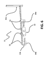
- FIG. 6 is a perspective view of the jig employed to position the extensometer and related elements on the FEL arm of a waste-hauling vehicle.
- FIG. 7 is a detailed perspective view of the extensometer mounted on the FEL arm of a waste-hauling vehicle, with the extensometer cover removed.
- FIG. 8 is a detailed perspective view of the extensometer mounted on the FEL arm of a waste-hauling vehicle, with the extensometer cover in place over the extensometer.
- FIG. 9 is a lateral view of the positioning jig in position on the FEL arm of a waste-hauling vehicle of the type including a dump-position stop plate.
- FIG. 10 is a detailed lateral view of the cut extensometer mount in position on the FEL arm of a waste-hauling vehicle.
- FIG. 11 is a perspective view of an alternative embodiment of the extensometer.
- the weighing system may be seen to comprehend, in the exemplary embodiment, some or all of the following components disposed on an otherwise conventional FEL-type waste-hauling vehicle 1 :
- At least one extensometer 10 is mounted on at least one FEL arm 2 of the vehicle 1 , the relatively moveable extensometer halves each secured to separate extensometer mounts 12 a , 12 b so that the extensometer 10 is operative to detect deflections in the arm 2 in response to loads of varying weights being supported thereby.
- an extensometer 10 is mounted to the arm 2 via the method described further below, although it will be appreciated that other methods may be employed.
- a cover 13 is disposed over the extensometer 10 , the cover 13 secured to the arm 2 via cover mounts 14 a , 14 b.
- At least one an extensometer 10 may be mounted in substantially the same location on each FEL arm 2 or, alternatively, that only a single extensometer 10 may be employed on only a single one of the arms 2 .
- the provision of at least two such extensometers 10 i.e., at least one on each arm will provide the weighing system with greater accuracy in determining weights as described below.
- a vehicle data hub (“VDH”) 30 is in communication with each of the one or more extensometers 10 (such as, for instance, via cables 40 ).
- the VDH 30 is mounted, for instance, between the cab and waste receptacle (e.g., the dump body) of the waste hauling vehicle 1 , such as via a bracket 31 .
- the VDH weighs a waste container on the “UP” cycle and again on the “DOWN” cycle of the lift; that is, the cycle of the FEL arms from the point of raising the waste container to dump into the vehicle dump body and back again to the point of lowering the waste container to the ground.
- the VDH 30 which comprises a weighing board, is operative to receive inputs from the extensometers 10 and determine therefrom: (i) the weight of a waste container holding waste as that waste container is lifted by the FEL arms for emptying into a waste receptacle (e.g., dump body) on the vehicle; (ii) the weight of the waste container as it is lowered by the FEL arms after the waste container has been emptied into the waste receptacle (e.g., dump body) on the vehicle; and (iii) the net weight of the waste that was contained in the container. More specifically, the extensometer creates a differential signal that is fed to an analog to digital converter (“ADC”).
- ADC analog to digital converter
- the voltage across the differential signal is proportional to the extension on the device.
- the signal is sampled at a regular interval during the lift operation and the average ADC code value is calculated for the up and the down direction of FEL movement.
- the up and down weight for the waste container are calculated from the calculated code values using a linear function.
- the net weight information so calculated is applied to the lift; that is, the net weight data is associated, in a computer database, with the lift event from which the net weight was determined.
- This information is displayed on the optional in-cab display unit 60 (discussed below) and is, moreover, communicated by the VDH 30 to the optional on-board computer 70 (discussed below) and/or to a remote location (such as, for instance, the waste-hauling vehicle's dispatch center, central office, etc.).
- the VDH 30 provides integrated general packet radio service (“GPRS”), GPS and WiFi, and RFID reading, as well as the ability to handle I/O signals.
- GPRS general packet radio service
- the VDH 30 is optionally capable of collecting and managing RFID, weight data, GPS coordinates and CANBus data through one single unit with, per the exemplary embodiment, greatly simplified wiring and installation. These data, or any of them, can then be relayed back, via the VDH's integral modem, in real time, to a remote location (such as the vehicle's dispatch center, central office, etc.) to be analyzed and used to track vehicle performance and location, and for invoicing and performance reporting.
- the VDH 30 is, optionally, a modular system available in a variety of configurations. A basic unit provides GPS tracking with GPRS communication, while multiple weighing and RFID reader modules can be added as required. Further, the VDH 30 can optionally be used in conjunction with an on-board computer 70 to provide driver interaction.
- a positional, or “tilt”, sensor 50 may be disposed on at least one FEL arm 2 of the vehicle 1 .
- the tilt sensor 50 is mounted on a cross-tube clamp 51 secured to the FEL arms' common cross-tube, although those skilled in the art will appreciate that other mounting arrangements are possible.
- the tilt sensor 50 is in communication with the VDH 30 (such, as, for instance, via wiring coupled to the tilt harness 41 ).
- the tilt sensor 50 is operative to measure the angular position of the at least one FEL arm 2 through its range of motion; and the VDH 30 receives inputs from the tilt sensor 50 and determines therefrom the height of the at least one FEL arm 2 through its range of motion. By these inputs from tilt sensor 50 , the VDH is operative to determine individual lift cycles and dynamic weighing windows.
- a display box 60 is provided in the cab of the waste-hauling vehicle 1 to display the weight of the waste container currently being weighed (as determined by the VDH 30 via inputs from the extensometer 10 ).
- Display 60 may, as in the exemplary embodiment, comprise a four-line LCD display and one or more LED lights indicating the status of the current lifting cycle. However, it will be appreciated that the particular type of display may be selected according to user desire.
- an on-board computer 70 is provided in the cab of the vehicle 1 .
- the on-board computer comprises, per the exemplary embodiment, an embedded, fanless PC with a solid state drive, a cab-mounted, touch-screen driver interface 71 , a GPRS modem and antenna, and a GPS receiver. Via the GPS receiver, the on-board computer may also be operative to determine the GPS location of the vehicle 1 at any given location and, thus, to associate the determined GPS location with each lift cycle of the FEL arms.
- the weighing system of the present disclosure is operative to weigh a waste container on the way “UP” and on the way “DOWN” during a lift cycle; the net weight is automatically calculated by the VDH (using inputs from the extensometer or extensometers) and displayed in the cab for the driver.
- the foregoing weighing function takes place in dynamic mode; that is, no static pause during the lift cycle of the FEL arms is needed to weigh the waste container.
- the weighing system of the present invention is preferably (though not necessarily) programmed to work automatically with no need for driver input.
- data including at least the determined net weight and, optionally, the GPS location of the vehicle where the net weight is determined
- a remote location such as, for instance, the vehicle's dispatch center, central office, etc.
- two extensometers 10 a , 10 b are mounted generally opposite each other on upper 2 a and lower 2 b surfaces of at least one of the FEL arms 2 , as shown in FIG. 2 .
- “(U ⁇ L)” represents calibration of the system (e.g., the VDH) for zero load applied to the FEL arm(s) 2 so that the difference between the output of the upper 10 a and lower 10 b extensometers is 0.
- the signal U from the upper 10 a extensometer has a first “polarity” (e.g., positive) because it is in tension
- the signal L from the lower extensometer 10 b has the opposite “polarity” (e.g., negative) because it is in compression.
- a still further benefit from the foregoing embodiment of the present invention is the automatic correction for common mode offsets. For instance, it is the case that where only a single extensometer is employed on a surface of the FEL arm, an increase in ambient temperature causes the FEL arm 2 to expand, making it difficult to distinguish between the effects of an increase in load versus those of the temperature increase. Because a temperature increase will cause the FEL arm(s) to expand proportionally along both of the upper 2 a and lower 2 b surfaces thereof, the difference between the two signals (i.e., U ⁇ L) will effectively cancel out the temperature-induced offset, leaving only the deflection due to the applied load in the difference calculation.
- U ⁇ L the difference between the two signals
- extensometers 10 a , 10 b on opposite surfaces of an FEL arm automatically negates the otherwise distorting effects the temperature increase would have on an extensometer applied to only one (upper or lower) surface of the FEL arm.
- two extensometers 10 c , 10 d are mounted in longitudinally spaced-apart locations on the same FEL arm 2 .
- those spaced-apart locations may be on either the same surface (e.g., the upper surface 2 a , as shown in FIG. 3 ) or on different surfaces (i.e., the upper 2 a and lower 2 b surfaces, as shown in FIG. 4 ).
- each at least one extensometer 10 to an FEL arm 2 of a vehicle will be more particularly described.
- the following exemplary method is described in respect of placement of an extensometer on a single FEL arm of a waste-hauling vehicle; however, it is contemplated that the present invention may employ extensometers mounted to each of the pair of FEL arms comprising a conventional FEL-type waste-hauling vehicle.
- the extensometer(s) may be mounted other than as described herebelow; and, conversely, that the extensometer mounting method may be used to mount one or more extensometers for use in a weighing system other than as described herein.
- a positioning jig 11 having a principal length extending between first 11 a and second 11 b ends, the first end 11 a defining a frame of reference for orienting the jig on the FEL arm.
- the first end 11 a more particularly defines an end-plate oriented generally orthogonal to the principal length.
- the jig 11 has removably connected thereto by bolts 15 (or other selectively removable fastening means) along the principal length each of an unitary mount 12 for the extensometer 10 and a pair of mounts 14 a , 14 b for a cover 13 .
- the configuration of the positioning jig 11 ensures proper relative spacing along the FEL arm 2 of the cover mounts 14 a , 14 b and the unitary extensometer mount 12 , as well as the proper alignment of their respective bottom surfaces along a desired plane (such as a common plane) to ensure accurate placement of these various mounts 12 , 12 a , 14 b on the surface of the FEL arm 2 .
- the unitary extensometer mount 12 comprises first 12 a and second 12 b portions each having a first thickness, the first and second portions being spaced apart from each other by an intermediate portion 12 c having a second thickness that is less than the first thickness.
- the intermediate portion 12 c is positioned between the first 12 a and second 12 b portions so as to leave a gap G beneath the intermediate portion 12 c and between the first 12 a and second 12 b portions.
- extensometer mount 12 depicted in the exemplary embodiment is not intended to be limiting of the claimed invention.
- the jig 11 is placed on the arm 2 so that the first end 11 a is positioned in a predefined location relative to a known location on the FEL arm.
- the FEL arm 2 is of the type that includes a dump position stop-plate 3 , such as shown in FIG. 9
- the jig 11 is positioned so that the first-end 11 a end-plate abuts the dump position stop-plate 3 .
- the FEL arm 2 is of the type that does not include a dump position stop-plate but does include a plug weld hole proximate a stopper buffer area of the arm 2
- the first step comprises placing the jig 11 so that the first end 11 a is positioned a predefined distance from the plug weld hole.
- the configuration of the positioning jig 11 and its placement relative to the defined locations on each FEL arm ensures proper positioning on the FEL arm of each of the a unitary mount 12 for the extensometer 10 and the cover mounts 14 a , 14 b.
- the cover mounts 14 a , 14 b and the unitary extensometer mount 12 are secured to the arm 2 while the positioning jig 11 is maintained in its proper position as heretofore defined. In the exemplary embodiment, this is first, provisionally accomplished by tack welding. Following disconnection of the positioning jig 11 , the cover mounts 14 a , 14 b and the unitary extensometer mount 12 are more securely welded in place.
- the positioning jig 11 is disconnected (i.e., by removing bolts 15 ) from each of the cover mounts 14 a , 14 b and the unitary extensometer mount 12 . As indicated, the mounts 12 , 14 a , 14 b are then securely welded in place.
- the unitary extensometer mount 12 is cut to define two completely separate extensometer mounts 12 a ′, 12 b ′.
- this step more particularly comprises cutting the intermediate portion 12 c of the unitary extensometer mount 12 so that there is an approximately 10 cm gap between the separate extensometer mounts 12 a ′, 12 b ′ defined by the cut.
- the extensometer 10 which, per convention, is comprised of two portions (each labeled 10 ) that are moveable relative to each other—is in a subsequent step secured to the separate extensometer mounts 12 a ′, 12 b ′ (using the bolts 15 provided to secure the unitary extensometer mount 12 to the jig 11 ). It will be appreciated by those skilled in the art that such separate mounting as provided by the extensometer mounts 12 a ′, 12 b ′ is necessary so that the extensometer 10 is able to detect deflections in the arm 2 in response to loads of varying weights.
- a cover 13 is positioned over the extensometer 10 and connected to each of the cover mounts 14 a , 14 b using the bolts 15 provided to secure the cover mounts 14 a , 14 b to the jig 11 .
- the extensometer 10 is, according to the exemplary embodiment herein described, positioned on a portion of each FEL arm 2 which is characterized as being substantially horizontally oriented when the FEL arm 2 is in a fully lowered position relative to the waste-hauling vehicle 1 .
- either of (i) the two portions of the extensometer 10 ′′ or (ii) the associated extensometer mounts 12 a , 12 b (not depicted in FIG. 11 ) are fashioned from a relatively harder material than the material used to fashion the other.
- the one of the extensometer 10 ′′ (in the embodiment of FIG. 11 it will be appreciated to be the extensometer) or its associated mounts 12 a , 12 b fashioned from the harder material is provided with one or more projections 16 ′′, such as teeth, splines, ridges, etc. which extend outwardly from the mounting surface so as to face the other of the extensometer or its mount.
- the one or more projections will, under suitable force, create corresponding recesses in the softer material of the other of the extensometer or its mount. These will uniquely register the portions of the extensometer 10 ′′ and mounts 12 a , 12 b in a zero-tolerance relationship, such that any movement in one of the extensometer portions or the mounts will be completely transferred between them.
- the foregoing optional variation precludes relative slippage between an extensometer and its associated mounts, which slippage would otherwise potentially interfere with the weight determination as such slippage consumes motion that would otherwise be sensed by the extensometer.
- one or more washers are provided between each extensometer and the bolts 15 when securing the extensometer 10 to mounts 12 a ′, 12 b ′.
- a suitable thread-locking adhesive is applied to the threads of the bolts 15 so as to securely fix the bolts—and, relatedly, the extensometer—to mounts 12 a ′, 12 b ′.
- Either or both of the foregoing options serve to prevent the bolts 15 from subsequently loosening due to vibration or shock encountered during operation of the vehicle.
- the present invention is readily retrofitted to any FEL-type waste-hauling vehicle, and that no modification to the FEL arms is required.
- the present inventive weighing system provides not only accurate weight information but, optionally, a GPS location for each lift, as well as optional automatic data transfer to the vehicle's dispatch center or other desired, remote location.
- the weighing system of the present disclosure provides numerous benefits, including, without limitation, assisting commercial waste haulers in the identification of profitable accounts, service activity, etc., thereby increasing the efficiency and accountability of commercial waste collections.
- the weighing system is robust, requiring virtually no maintenance, while calibration is carried out only at the time of system installation. As the weighing system doesn't rely on load cells, it is more reliable than conventional weighing solutions and, moreover, presents a low risk for damage.
Abstract
Description
(U−L)=0; and
(U−(−L))=U+L
W×(Z)=WZ;
W×(Z+Y)=WZ+WY; and
(WZ+WY)−(WZ)=WY
Claims (17)
Priority Applications (1)
| Application Number | Priority Date | Filing Date | Title |
|---|---|---|---|
| US14/698,971 US9586756B2 (en) | 2014-04-29 | 2015-04-29 | Weighing system for a front-end-loading waste-hauling vehicle |
Applications Claiming Priority (2)
| Application Number | Priority Date | Filing Date | Title |
|---|---|---|---|
| US201461985737P | 2014-04-29 | 2014-04-29 | |
| US14/698,971 US9586756B2 (en) | 2014-04-29 | 2015-04-29 | Weighing system for a front-end-loading waste-hauling vehicle |
Publications (2)
| Publication Number | Publication Date |
|---|---|
| US20150307274A1 US20150307274A1 (en) | 2015-10-29 |
| US9586756B2 true US9586756B2 (en) | 2017-03-07 |
Family
ID=53488840
Family Applications (1)
| Application Number | Title | Priority Date | Filing Date |
|---|---|---|---|
| US14/698,971 Active US9586756B2 (en) | 2014-04-29 | 2015-04-29 | Weighing system for a front-end-loading waste-hauling vehicle |
Country Status (3)
| Country | Link |
|---|---|
| US (1) | US9586756B2 (en) |
| AU (1) | AU2015202184B2 (en) |
| GB (2) | GB2554836B (en) |
Cited By (6)
| Publication number | Priority date | Publication date | Assignee | Title |
|---|---|---|---|---|
| US10594991B1 (en) | 2018-01-09 | 2020-03-17 | Wm Intellectual Property Holdings, Llc | System and method for managing service and non-service related activities associated with a waste collection, disposal and/or recycling vehicle |
| US11373536B1 (en) | 2021-03-09 | 2022-06-28 | Wm Intellectual Property Holdings, L.L.C. | System and method for customer and/or container discovery based on GPS drive path and parcel data analysis for a waste / recycling service vehicle |
| US11386362B1 (en) | 2020-12-16 | 2022-07-12 | Wm Intellectual Property Holdings, L.L.C. | System and method for optimizing waste / recycling collection and delivery routes for service vehicles |
| US11475417B1 (en) | 2019-08-23 | 2022-10-18 | Wm Intellectual Property Holdings, Llc | System and method for auditing the fill status of a customer waste container by a waste services provider during performance of a waste service activity |
| US11488118B1 (en) | 2021-03-16 | 2022-11-01 | Wm Intellectual Property Holdings, L.L.C. | System and method for auditing overages and contamination for a customer waste container by a waste services provider during performance of a waste service activity |
| US11928693B1 (en) | 2021-03-09 | 2024-03-12 | Wm Intellectual Property Holdings, L.L.C. | System and method for customer and/or container discovery based on GPS drive path analysis for a waste / recycling service vehicle |
Families Citing this family (5)
| Publication number | Priority date | Publication date | Assignee | Title |
|---|---|---|---|---|
| US9926134B2 (en) * | 2013-10-01 | 2018-03-27 | The Curotto-Can, Llc | Biasing cradle for refuse vehicle |
| CN105373104A (en) * | 2015-12-02 | 2016-03-02 | 天津港远航矿石码头有限公司 | Operation control system of loader |
| CN106779155A (en) * | 2016-11-16 | 2017-05-31 | 安徽省光阴碎片智能科技有限公司 | A kind of environmental sanitation supervising platform |
| CN108584251A (en) * | 2018-04-28 | 2018-09-28 | 北京时代凌宇科技股份有限公司 | A kind of dustbin lifting jack and garbage truck |
| CN111846714B (en) * | 2020-07-29 | 2022-05-03 | 深圳东风汽车有限公司 | Self-adaptive fuzzy loading capacity control method and system for garbage truck |
Citations (13)
| Publication number | Priority date | Publication date | Assignee | Title |
|---|---|---|---|---|
| US4042049A (en) | 1975-09-29 | 1977-08-16 | Structural Instrumentation, Inc. | Vehicle load measuring system |
| US4239437A (en) * | 1978-10-20 | 1980-12-16 | Zoller-Kipper Gmbh | Heavy duty receptacle unloading device for trucks |
| US5178226A (en) | 1990-12-21 | 1993-01-12 | Allan Bowman | Load measuring system for refuse trucks |
| US5190116A (en) | 1990-02-13 | 1993-03-02 | Stress-Tek, Inc. | Deflection transducer for measuring vehicle loads and a system for mounting same |
| US5195418A (en) | 1991-04-10 | 1993-03-23 | Wray-Tech Instruments, Inc. | Hydraulic control system for weighting and two-way valve therefor |
| US5209313A (en) | 1991-03-28 | 1993-05-11 | Teledyne Industries, Inc. | Lift weighing |
| US5245137A (en) | 1990-12-21 | 1993-09-14 | Mobile Computing Corporation | Load measuring system for refuse trucks |
| WO1997004289A1 (en) | 1995-07-18 | 1997-02-06 | Maywood Instruments Limited | Strain measuring devices, and monitoring of vehicle container loads |
| US5703333A (en) | 1996-01-23 | 1997-12-30 | Wray-Tech Instruments, Inc. | Surface mount torque loadcell |
| US5917159A (en) | 1996-09-20 | 1999-06-29 | Mobile Advanced Scale Systems Corp. | Dynamic load weighing system |
| US20060064264A1 (en) * | 2003-05-13 | 2006-03-23 | Pottebaum James R | Load cells for use in high precision load measuring system |
| US20120285750A1 (en) | 2011-05-12 | 2012-11-15 | Advanced Manufacturing Control Systems Ltd. | Weight measurement system for accurately determining the weight of material in a container being lifted |
| US20140060939A1 (en) * | 2011-05-13 | 2014-03-06 | David Aaron Eppert | Load-measuring, fleet asset tracking and data management system for load-lifting vehicles |
Family Cites Families (2)
| Publication number | Priority date | Publication date | Assignee | Title |
|---|---|---|---|---|
| US5083624A (en) * | 1990-02-13 | 1992-01-28 | Stress-Tek, Inc. | Deflection transducer for measuring vehicle loads and a system for mounting same |
| EP0927340A1 (en) * | 1996-09-20 | 1999-07-07 | Walter Kostiuk | Dynamic load weighing system |
-
2015
- 2015-04-29 AU AU2015202184A patent/AU2015202184B2/en active Active
- 2015-04-29 US US14/698,971 patent/US9586756B2/en active Active
- 2015-04-29 GB GB1721194.7A patent/GB2554836B/en active Active
- 2015-04-29 GB GB1507288.7A patent/GB2526687A/en not_active Withdrawn
Patent Citations (13)
| Publication number | Priority date | Publication date | Assignee | Title |
|---|---|---|---|---|
| US4042049A (en) | 1975-09-29 | 1977-08-16 | Structural Instrumentation, Inc. | Vehicle load measuring system |
| US4239437A (en) * | 1978-10-20 | 1980-12-16 | Zoller-Kipper Gmbh | Heavy duty receptacle unloading device for trucks |
| US5190116A (en) | 1990-02-13 | 1993-03-02 | Stress-Tek, Inc. | Deflection transducer for measuring vehicle loads and a system for mounting same |
| US5245137A (en) | 1990-12-21 | 1993-09-14 | Mobile Computing Corporation | Load measuring system for refuse trucks |
| US5178226A (en) | 1990-12-21 | 1993-01-12 | Allan Bowman | Load measuring system for refuse trucks |
| US5209313A (en) | 1991-03-28 | 1993-05-11 | Teledyne Industries, Inc. | Lift weighing |
| US5195418A (en) | 1991-04-10 | 1993-03-23 | Wray-Tech Instruments, Inc. | Hydraulic control system for weighting and two-way valve therefor |
| WO1997004289A1 (en) | 1995-07-18 | 1997-02-06 | Maywood Instruments Limited | Strain measuring devices, and monitoring of vehicle container loads |
| US5703333A (en) | 1996-01-23 | 1997-12-30 | Wray-Tech Instruments, Inc. | Surface mount torque loadcell |
| US5917159A (en) | 1996-09-20 | 1999-06-29 | Mobile Advanced Scale Systems Corp. | Dynamic load weighing system |
| US20060064264A1 (en) * | 2003-05-13 | 2006-03-23 | Pottebaum James R | Load cells for use in high precision load measuring system |
| US20120285750A1 (en) | 2011-05-12 | 2012-11-15 | Advanced Manufacturing Control Systems Ltd. | Weight measurement system for accurately determining the weight of material in a container being lifted |
| US20140060939A1 (en) * | 2011-05-13 | 2014-03-06 | David Aaron Eppert | Load-measuring, fleet asset tracking and data management system for load-lifting vehicles |
Cited By (17)
| Publication number | Priority date | Publication date | Assignee | Title |
|---|---|---|---|---|
| US10750134B1 (en) | 2018-01-09 | 2020-08-18 | Wm Intellectual Property Holdings, L.L.C. | System and method for managing service and non-service related activities associated with a waste collection, disposal and/or recycling vehicle |
| US10855958B1 (en) | 2018-01-09 | 2020-12-01 | Wm Intellectual Property Holdings, Llc | System and method for managing service and non-service related activities associated with a waste collection, disposal and/or recycling vehicle |
| US10911726B1 (en) | 2018-01-09 | 2021-02-02 | Wm Intellectual Property Holdings, Llc | System and method for managing service and non-service related activities associated with a waste collection, disposal and/or recycling vehicle |
| US11128841B1 (en) | 2018-01-09 | 2021-09-21 | Wm Intellectual Property Holdings, Llc | System and method for managing service and non service related activities associated with a waste collection, disposal and/or recycling vehicle |
| US11140367B1 (en) | 2018-01-09 | 2021-10-05 | Wm Intellectual Property Holdings, Llc | System and method for managing service and non-service related activities associated with a waste collection, disposal and/or recycling vehicle |
| US11172171B1 (en) | 2018-01-09 | 2021-11-09 | Wm Intellectual Property Holdings, Llc | System and method for managing service and non-service related activities associated with a waste collection, disposal and/or recycling vehicle |
| US11616933B1 (en) | 2018-01-09 | 2023-03-28 | Wm Intellectual Property Holdings, L.L.C. | System and method for managing service and non-service related activities associated with a waste collection, disposal and/or recycling vehicle |
| US10594991B1 (en) | 2018-01-09 | 2020-03-17 | Wm Intellectual Property Holdings, Llc | System and method for managing service and non-service related activities associated with a waste collection, disposal and/or recycling vehicle |
| US11425340B1 (en) | 2018-01-09 | 2022-08-23 | Wm Intellectual Property Holdings, Llc | System and method for managing service and non-service related activities associated with a waste collection, disposal and/or recycling vehicle |
| US11475416B1 (en) | 2019-08-23 | 2022-10-18 | Wm Intellectual Property Holdings Llc | System and method for auditing the fill status of a customer waste container by a waste services provider during performance of a waste service activity |
| US11475417B1 (en) | 2019-08-23 | 2022-10-18 | Wm Intellectual Property Holdings, Llc | System and method for auditing the fill status of a customer waste container by a waste services provider during performance of a waste service activity |
| US11386362B1 (en) | 2020-12-16 | 2022-07-12 | Wm Intellectual Property Holdings, L.L.C. | System and method for optimizing waste / recycling collection and delivery routes for service vehicles |
| US11790290B1 (en) | 2020-12-16 | 2023-10-17 | Wm Intellectual Property Holdings, L.L.C. | System and method for optimizing waste / recycling collection and delivery routes for service vehicles |
| US11373536B1 (en) | 2021-03-09 | 2022-06-28 | Wm Intellectual Property Holdings, L.L.C. | System and method for customer and/or container discovery based on GPS drive path and parcel data analysis for a waste / recycling service vehicle |
| US11727337B1 (en) | 2021-03-09 | 2023-08-15 | Wm Intellectual Property Holdings, L.L.C. | System and method for customer and/or container discovery based on GPS drive path and parcel data analysis for a waste / recycling service vehicle |
| US11928693B1 (en) | 2021-03-09 | 2024-03-12 | Wm Intellectual Property Holdings, L.L.C. | System and method for customer and/or container discovery based on GPS drive path analysis for a waste / recycling service vehicle |
| US11488118B1 (en) | 2021-03-16 | 2022-11-01 | Wm Intellectual Property Holdings, L.L.C. | System and method for auditing overages and contamination for a customer waste container by a waste services provider during performance of a waste service activity |
Also Published As
| Publication number | Publication date |
|---|---|
| GB2554836A (en) | 2018-04-11 |
| AU2015202184A1 (en) | 2015-11-12 |
| GB201721194D0 (en) | 2018-01-31 |
| US20150307274A1 (en) | 2015-10-29 |
| GB2554836B (en) | 2018-08-15 |
| GB2526687A (en) | 2015-12-02 |
| GB201507288D0 (en) | 2015-06-10 |
| AU2015202184B2 (en) | 2017-06-15 |
Similar Documents
| Publication | Publication Date | Title |
|---|---|---|
| US9586756B2 (en) | Weighing system for a front-end-loading waste-hauling vehicle | |
| US20170254694A1 (en) | Onboard load weight measurement system for vehicles, with a multipoint automatic and semi-automatic calibration system | |
| US8630753B2 (en) | Method for dynamic determination of the true mass of a non rigid body subject to low frequency noise | |
| CN101788326A (en) | Weighing device of dump truck | |
| CN202471205U (en) | Dynamic vehicle load detection device | |
| CN208984201U (en) | Semitrailer vehicle-mounted weighing system and semitrailer | |
| CN101603852A (en) | Truck scale dynamic axle weighing system | |
| US4789033A (en) | Onboard weight indicator for vehicles | |
| SE523352C2 (en) | Cargo calculation system for cargo vehicles | |
| CA2911768C (en) | Elastically deformable load bearing structure comprising a measuring assembly for the load | |
| CN206460325U (en) | A kind of pure electronic logistic car multifunction monitoring system | |
| CN201354031Y (en) | Dump truck weighing device | |
| GB2191868A (en) | Vehicle load display | |
| AU605838B2 (en) | Method for displaying load distribution by monitoring a work vehicle suspension | |
| CN207540650U (en) | A kind of medical waste transfer car weighing system | |
| EP0218466A1 (en) | Vehicle load monitoring system | |
| AU2018337664A1 (en) | Weight management system for a towed vehicle | |
| CN205228611U (en) | Vehicle number of axles recognition device | |
| CN103909858A (en) | Plate spring suspension vehicle self-weighing system | |
| CN210513374U (en) | Unattended weighbridge | |
| EP2105717B1 (en) | Method for defining the load weighing on an axle with mechanical suspension in a vehicle provided with at least an axle with pneumatic suspension provided with load detection system | |
| CN210293413U (en) | Vehicle-mounted self-weight device | |
| EP2075145A1 (en) | Method and system for detecting the load of a vehicle equipped with non-pneumatic suspensions | |
| CN201872659U (en) | Dumper capable of weighting loaded goods by self | |
| KR100831764B1 (en) | Truck scale for axial load detecting plate include |
Legal Events
| Date | Code | Title | Description |
|---|---|---|---|
| AS | Assignment |
Owner name: ADVANCED MANUFACTURING CONTROL SYSTEMS LIMITED, IR Free format text: ASSIGNMENT OF ASSIGNORS INTEREST;ASSIGNORS:HYNES, EAMON;O'RIORDAN, GARY;BRODERICK, CORNELIUS;REEL/FRAME:041025/0881 Effective date: 20161103 |
|
| AS | Assignment |
Owner name: ADVANCED MANUFACTURING CONTROL SYSTEMS LIMITED, IR Free format text: CORRECTIVE ASSIGNMENT TO CORRECT THE ASSIGNEE'S CITY NAME PREVIOUSLY RECORDED ON REEL 041025 FRAME 0881. ASSIGNOR(S) HEREBY CONFIRMS THE ASSIGNMENT;ASSIGNORS:HYNES, EAMON;O'RIORDAN, GARY;BRODERICK, CORNELIUS;REEL/FRAME:041469/0309 Effective date: 20161103 |
|
| AS | Assignment |
Owner name: ADVANCED MANUFACTURING CONTROL SYSTEMS LIMITED, IR Free format text: EMPLOYMENT AGREEMENT;ASSIGNOR:LAWLOR, THOMAS (TOM);REEL/FRAME:041482/0142 Effective date: 20081015 |
|
| STCF | Information on status: patent grant |
Free format text: PATENTED CASE |
|
| MAFP | Maintenance fee payment |
Free format text: PAYMENT OF MAINTENANCE FEE, 4TH YEAR, LARGE ENTITY (ORIGINAL EVENT CODE: M1551); ENTITY STATUS OF PATENT OWNER: LARGE ENTITY Year of fee payment: 4 |
|
| AS | Assignment |
Owner name: WILMINGTON TRUST (LONDON) LIMITED, UNITED KINGDOM Free format text: SECURITY INTEREST;ASSIGNOR:ADVANCED MANUFACTURING CONTROL SYSTEMS LIMITED;REEL/FRAME:060580/0001 Effective date: 20220706 |