US958512A - Braiding-machine. - Google Patents
Braiding-machine. Download PDFInfo
- Publication number
- US958512A US958512A US48791709A US1909487917A US958512A US 958512 A US958512 A US 958512A US 48791709 A US48791709 A US 48791709A US 1909487917 A US1909487917 A US 1909487917A US 958512 A US958512 A US 958512A
- Authority
- US
- United States
- Prior art keywords
- thread
- devices
- threads
- controlling
- sets
- Prior art date
- Legal status (The legal status is an assumption and is not a legal conclusion. Google has not performed a legal analysis and makes no representation as to the accuracy of the status listed.)
- Expired - Lifetime
Links
Images


Classifications
-
- D—TEXTILES; PAPER
- D04—BRAIDING; LACE-MAKING; KNITTING; TRIMMINGS; NON-WOVEN FABRICS
- D04C—BRAIDING OR MANUFACTURE OF LACE, INCLUDING BOBBIN-NET OR CARBONISED LACE; BRAIDING MACHINES; BRAID; LACE
- D04C3/00—Braiding or lacing machines
Definitions
- Patented may 17, w10.
- Fi ure 1 is a plan, partly in section, of a my present in vention
- Fig. 2 is a central vertical section of the same. the section being taken in the line 2 2, Fig. 1;
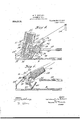
- Fig. 3 is an enlarged plan of a portion of the machine shown in Fig. 1, and illustrates in greater detail than 1u said figure various thread-supplying and pattern-controlling devices;
- Iig. 4 is an enlarged sectional detail, the section being taken in the line-1 4, Fig.
- FIG. 5 is a substantially similar sectional detail illustrating the manner in which the outer threads are raised above i the inner threads h'yr means of a switchating parts and illustrates the manner in which the -outer thread is raised above its..
- Fig. 7 is an enlarged sectional detail, taken in the line 7 7, Iig. 6, and illustrates the manner in which the pattern-controlling device is operated and operates
- Fig. 8 is an enlarged sectional detail similar to Fig. 5 and illustrates the pattern-controlling device and a cooperating switch-plate 1n a position to permit an outer thread to pass the pattern-controlling device while said thread is held below its normal line of travel and below the inner thread with which it is interlaced
- Fi 9 is an enlarged sectional detail similar to Fig. 8, illustrating the opposite condition, that is,l the parts in position with the outer thread raised above its normal line of travel and above the inner thread and with the pattern-controlling device in position to close the path for the thread illustrated in Fig. 8
- Fig. 10 is an enlarged detail illustrating in sectional plan the construction of one of the pattern-changing devices, and
- Fig. 11 is a pergspective of a removable sec ⁇ tion'of one of the carriers for the bobbins.
- Figsrl and 2 many of the parts o the machine are preferably substantially the same as in braidin machines heretofore constructed, and for t e pur ose of illustration these parts are so shown. or example, the machine shown in these views is illustrated as having a bed or base' 2 from which rise's s hollow xed post 3 having an external jonrnal surface on which turns a lon sleeve 4.
- this s eeve 4 has secured thereto a large bevelear 5 by means of which the sleeve 1s rotate and at a point a considerable distance above said bevel-gear said sleeve has an annular support 6 for' another large bevel-gear 7 which is fixed to the hub rtion 8 of the rotary carrier 9 journale on the upper portion of the sleeve 4.
- the rotary cai'rier or table 9 in turn constitutes a support for the hub portion 10 1f-another rotary carrier or table 11, which is fixed to the upper end of the sleeve 4.
- the two carriers or tables 9 and 11 are intended to be rotated in opposite directions by means of the gears 5 and 7, these being driven in the usual hihnner by a bevel-gear 13 .secured to the end of a main driving-shaft 1G mounted in suitable bearingssueh as 1T and 1H. ris ing from the base of the machine, said shaft having at its end the usual fast-and-loose pulleys 19 and Q0. ,lt the outer end ol'A the tubular base 3 is placed a stop 2l for limiting upward movement of the carrier 1l.
- the two carriers -9 and l1 support, as is usual, two sets of thread-supplyin nr devices, which are generally in the form o t' bobbins mounted on bobbin-holders, one set being located outside the other and se positioned that the threads of one se*J may be readily shifted to one side or the other of the threads of the other set and interlaced therewith as they pass the threads of such other set.
- bobbin-holders In Fig. 1, eight sets of bobbin-holders are shown on each carrier and each holder carries a bobbin.
- the bobbin-holders of the outer set are designated respectively by 25 and those, of the inner set by 26. Corres ondingly the bobbins of the outer set. are
- each bobbin-holder is merely a spindle or pin fixed at its outer end to its carrier and free at its inner end to permit its bobbin to be quickly placed in position or removed. This reduces considerably the wei ht of the parts to be rotated and also faci itates the insertion of filled bobbins and force during rotation of their carriers, while at the same time permitting the threads to pass properly from the bobbxns to the braid- .ing point.
- '.l'he thread from cach of these outer bobbins is also shown as guided and tensioned by a threzul-g'ulde and a tensicn device carried directly by said lower carrier t), these thread guides and tension devices being designated respectively b v 2S), Ztl and llt).
- the bobbinholdersI otl the inner set are not, however, in this construction carried directly by the table ll, but are mounted on s ⁇ vitchplatcs ,l
- switch-plate is preferably a curved member shaped lo conform to the contour of the guidewa)Y 3l in which it is to travel and having a supporlin,r face 31 to which a switch-plate may be secured.
- Switch-plates of suitable construction are secured to these carrier-segments and move therewith in a direction opposite to the direction of travel of the car-- rier i) and its annnlus 32, the function of these switch-plates being to control the inanner in which the threads of the outer set are interlaced with the threads of the inner set and thereby control the pattern braided by the machine.
- the switch-plates employed are preferably of the type or construction illustrated at.
- Each is a pointed segment with a wide central portion, it being so constructed as to guide one of the outer threads over either its inner or its outer face, so that the threads will pass either above or below. as the case may be, the normal line of travel of tie-e threads of the inner set.
- Each plate if n ferably disposed with its face substantialiy perpendicular to the line of travel of said inner threads.
- each switch-plate is disposed above the normal path of travel of the threads of the outer set, and the switchplate normally operates to depress the threads of the outer set belowv the threads of the inner set and thus interlace the same as the two sets pass each other traveling in o ,posite directions.
- pattern-changing devices together with certain other parts which will be hereinafter referred to, constitute in the construction illustrated herein the means for connecting t-he spider-armed carrier 11 with the segmental elements 34 of the upper carrier and with the switch-plates, bobbin-holders, etc., supported by said segments.
- each pattern-chan ing device is illustrated as a rotary mem er 36 supported at its opposite ends for rotation Vbetween the ends of a pair of spider-arms 37 of the carrier 11, these arms being here divided at their free ends in such a manner as to form separate supports for the ends of different rotary patternchanging members 36.
- Each of the rotary parts 36 isillustrated ⁇ (see Fig. 10) trunnionsdlat its opposite ends on pins 38 and as having extending lengthwise thereof spiral grooves 39 into which pass at intervals driving-pins 41 projecting up from the lower carrier 9.
- the guide-grooves of the rotary members 36 are here shown as four in mn ber, and the driving-pins 40 move into and ont of these grooves successively in such a manner that as'one pin is withdrawing from a spiral groove 39 another pin 40 is entering another of the grooves 39 of the same rotary member, thus assuring a positive rotation of A this rotary pattern-changing member.
- These members 36 have at their ends plates, such as 41, With f0ur projecting lingers, which in the rotation of the parts 36 enter and pass lthrough slots in ears fastened to the switch-plates at opposite ends thereof.
- the constmction is such that the rotary patternchanging'elements 315 with their end plates are always in engagement with at least one of the ears 42 with which they ooperate. and hence are always in positive driving connection with the switch-plates and the earlier-segments 34, which are thus always carried positively in their orbits by these connections from the spider-armed carrier.
- EachA switch-plate is also shown as having a thread-guide 43 for one of the threads of the inner set.
- Each of the rotary elements 36 carries in Y addition to the parts before described one o.'l more .thread-shifting devices constituting the pattern-changing devices proper.
- These thread-shifting devices may be of any suitable type and ⁇ construction so long as they are capable of performing the functions specified.
- each is ay light piece of wire curved to form a projection of suflcient extent for raising the louter threads as they pass under those threads.
- These wires are indicated -at 44, there being preferably two for each of the rotaryelemcnts 36.
- These thread-shifting devices are preferably spring wires and may be snapped into proper locking sockets atopposite ends of the arts 36, such as the L- haped sockets 45 (gee Fig. 10).
- the rotation of said parts affords one means for controlling the pattern made by the machine, that is to say, the wires move ⁇ in paths such that at definite periods they shift the outer threads above' their normal line of travel and above the normal line of travel of the forward ends of the switch-plates.
- the high ipoint of eatt thread-shifting device 44 is adjacent to l the forward end of a switch-plate at the ,moment when one of theoater threads is to bel raised (sce Fig. 3), at which time the device 4l may operate to raise the thread so that it will pass along the upper edge of the next switch-plate instead of following its normal path under the lower edgf of said switch-plate.
- a removable section of the ring 32 in which is formed the guideway for the carrier-segments.
- lhis removable section is long enough to permit the carrier-segments 3l with their ⁇ attached switch-plates, bobbinholders, etc., to be dropped into the guideway 31 through the ,opening presented .at said point at the top of the ring 32 and then shifted to their proper orbital positions.
- the section -t6 of the ring may be fastened iu position as illustrated in full lines in Fig. 9, to close the openinv.-
- Various features of the machine require no extended description.
- any suitable means may be employed for controlling the movements of the threads of the inner set including the tension thereof.
- spring-catches or detents are illustrated at, 47 for holding the bobbins of thelinner set in place on their switch-plates.
- one of said thread-gniding devices being operative to direct the passage of one thread to either one side or the. other ofthe other thread and the other of said thread-guiding devices being movable to dillcrent positions relative to said first-mentioned thread-guid-l ing device and thereby controlling the thread guiding operation ot' the latter.
- a braiding machine the combination with a pair of thread-supplying devices, of means for supporting said devices and moving them in opposite orbits, and means embodying two cooperative thread -guiding devices associated and moving orbitallv with one ot' said thread-supplying devices and controlling the intel-lacing of the threads, one ot' said thread-guiding devices haria operative. lo direct the passage of one thread to either one side or the other of the other thread and the other of said thread-guiding devices being rotativly movable to dilferent positions relative. to said first-mentioned thread-guiding device and thereby controlling the thread guiding operation of the latter.
- a braiding machine the combination with a pair of thread-supplying devices, ot' a pair ot' rotary carriers supporting said thread-supplying devices respectively, means for rotating said carriers in opposite directions, and means embodying two coperative thread-guiding devices associated and movable orbitally with one of said threadsupplying devices and controlling the interlacing of the threads, one of said threadguiding devices being'operativtl to direct the passage ot one thread to either one side or the other of the other thread aud the other of said tlu'ead-guiding devices being movable to di'erent positions relative to Said first-mentioned thread-guiding device and 'thereby controlling the thread guiding opertion of the latter.
- a braiding machine the combination with a. air of thread-supplying devices, of means or supporting said devices and moving them in opposite orbits, means embodying two coperative thread-guiding devices llO enana i 5' associated and movable orbitally with one of said thread-supplying devices and Jcontrollin the interlacing of the threads, one of said thread-guiding devices being operative to direct the passage of one thread to either one side or the other of the other thread and the other or second of said thread-guiding devices being movable to different positions relative to said first-mentioned thread-guiding device and thereby controlling the thread raiding operation of the latter, and means ormoving said second thread-guiding device to its said different thread-controlling positions daring its orbital movement.
- a braiding machine the combination with a air of thread-supplying devices, of means or supporting said devices and moving them in opposite orbits, means embodying two coperative thread-guiding devices associated and movable orbitally with one of said thread-supplying devices and Vcontrolling the interlacing of the threads, one of said thread-guiding devices being operative to direct the passage or one thread to either one Side or the other of the other thread and the other or second of said thread-guiding devices bein rotatively movable to different positions e ative to said first-mentioned thread-guiding device and thereby controlling the thread guiding operation of the latter, ⁇ and means for moving said second threed-guidin device to its said different thread-contro bital movements A 7.
- pattern-changing means movable orbitalily with one of said sets of thread-supplyingde- Y vices and controlling one set of threads, said pattern-changing means embodying a set 0f evices adjustable to different pattern-controlling positions determining the number and sequence of threads' of one set to pass at one side or the other of a thread of the other set.
- said pattern-clmngizzv means embodying a set of devices each ofb which adjustable separately to different attern-controlling positions determining t e number and uence o threads of one set to pass at one side or l* the other of l. thread of the other set.
- tionwi-th two' sets of thread-supplyin devices of means for supporting sai dcvices and movi-ng them 1n opposite orbits, pattern-changing means movable orbitally with one of said sets of thread-sn plying devices and controlling one set of tliireads, sxid pattern-changing means embodying a ad; of devices adjustable to different pattern-controlling positions determining the number and sequence of threads of one set to ass at one side or the other of athread ofp the other set, and means ,for imparting to said los' pattern-changing devices rotary threadshifting movements while thery are 4being carried in their orbits, 13.
- a braiding machine the combination with two sets of thread-supplying devices, of means for supporting said devices and moving them in op iosite orbits, a set of switch-plates normally controlling the interlacing of two sets of threads and having their forward ends above the normal lilie of travel of the outer set of threads, and pattern-changing means movable and cooperative with said switch-plates and embodying a set of devices adpistable to different pattern-controlling positions determining whether the threads of the uter set shall pass over or under the forward ends of the switch-plates.
- a braiding machine the combination with two sets ⁇ of thread-supplying devices, of means for supporting said devices and moving them in opposite orbits, a set of switch-plates normally controlling the interlacing o two sets of threads, and patternchanging means movable relatively to and co ⁇ o ⁇ erative with said switch-plates and contro ling one set of threads, said patternchangin means embodying a set. of devices adjustabe to differentpattern-controlling positions deterniinin whether said threads shall pass at one sidge or the other of said switch-plate.
- the. combinasets of bobina-holders, of a pair of rotary carriers supporting said bobbin-holders respectively means foivrotating said carriers in opposite directions,- a set of switch-plates, a set ot rotary patternchanging devices coperative with said switch-platos and controlling the iiumbei and sequence of threads ot' one set to pass "at one side or the other of threads of the other set, said switch-plates and pattern-- changin j devices being associated and movable wit one of said carriers, and a circuit of devices on the other carrier for intermittently engaging and rotating said patternchanging devices.
- a lset ofthread-shifting devices coperative with said switch-plates machine, the combinatary in controlling the interlacing of the two sets of threads, means for rotating said threadshifting devices in -planes passing through the axis of the orbit of their travel', and means carried by said thread-shitting devices or intermittently engaging and '.lriving said switchlates.
- a brai ing machine the combination with two sets of thread-supplying devices, of means includino' two rotary carriers for supporting said dievices and iriov'ing them in o iposite orbits, and a set ot threadweaving devices associated and movable orbitally with one of said sets of thread-snpplying devices and comprising a set of switch-plates slidably mounted on one of said rotary carriers, a set of thread-shifting devices mounted on the other oi" said rotary carriers and being coperative with said switch-plates in controlling the interlacing of the two sets of threads, means for rotating said thread-shitting devices in planes passing through the axis of the orbit of their travel, and means carried by said thread-shiftin devices for intermittently engaging and c riving said switch-plates.
- the combina.- tion with two sets of thread-supplying devices, of means include two rotary carriers for supporting said vices and moving their. in opposite orbits, and a set of threadwcaving devices associated and movable orbtally with one of said sets of thread-supplying devices and comprising a carrying nteans slidably mounted on one of said rocarriers, a set of switch-plates and one oi? said sets of thread-supplying devices mounted ci. said carrying means, a set of thread-shifting devices mounted on the other of said rotary carriers and being coperative with said switch-plates in controlling the interlacing of the two Sets of threads,
Description
W. T. LE BLANC.
BRAIDING MAGHIN APPLOATIOH FILED APB. 5. 1909.
Patented May 17, 1910.
B SHEETS-SHEET 1.
TTURNE Y W. T. LE BLANC.
BRAIDING MACHINE.
APPLICATION FILED un. 5. 1909.
Patented May 17, 1910.
6 SHEETS-SHEET 2.
` NVENH BY my QAM momr
W. T4. LE BLANC.
BRAIDING MACHINE.
APPLIOATION FILED APB.5,1909.
Patented May 17, 1910.
8 SHEETS-SHEET 3.
BRAIDING MACHINE.
Patented May 17, 1910.
APPLICATION FILED APB. 5. 1909.
B SHEETS-SHEET 4.
W. IT. LE BLANC. BRAIDING MACHINE.
APPLIOATIE FI LED APP.. 5. 1953.
Patented May 17, 1910.
6 SHEETS-SHEET 5.
BY i
W. T. LB BLANC.
BRAIDING MACHINE.
ummurou Hmm un. s. 190e.
958,5 1 2. Patented may 17, w10.
6 IISBTHIRBT 8;
5mm/10H WILLIAM T. LE BLANC, or NEW YORK, N. Y.
BRAIDIN G-MACHINE.
Specication of Letters-Patent.
Patented May 17, 1910.
Application filed April 5, 1909. Serial No. 487,91?.
To allwbom 'it may concern:
of this class of simple and cheap construction the parts of which are light and so organized as to render the machine capable of being run at higher speeds than machines as heretofore constructed, 1vvhile proy brai lng machine embodying ducing the bestresults in braiding.
@ne of the rinci al features of the machine. that distinguis es it from other braiding machines heretofore used is the employment of simple pattern-changing mechanism A:for producing at will braids having their threads interlaced in various ways, and this pattern-changing mechanism is so constructed and operated ns to produce various changesv in the mode of interlacing the threads and hence in the braid produced, b v mere adjustment of simple and light. threadweaving devices capable of effective operation at high speeds.
Other important features of the invention will be hereinafter described and claimed and are illustrated in the accompanying drawings` in which- Fi ure 1 is a plan, partly in section, of a my present in vention; Fig. 2 is a central vertical section of the same. the section being taken in the line 2 2, Fig. 1; Fig. 3 is an enlarged plan of a portion of the machine shown in Fig. 1, and illustrates in greater detail than 1u said figure various thread-supplying and pattern-controlling devices; Iig. 4 is an enlarged sectional detail, the section being taken in the line-1 4, Fig. 1, illustrating a pair of inner and outer bobbin-holders 'zoether with a pattern-controlling device for eterminin the manner in which the inner and outer t reads fed from the hobbins shall be interlaced; Fig. 5 is a substantially similar sectional detail illustrating the manner in which the outer threads are raised above i the inner threads h'yr means of a switchating parts and illustrates the manner in which the -outer thread is raised above its..
normal line of travel; Fig. 7 is an enlarged sectional detail, taken in the line 7 7, Iig. 6, and illustrates the manner in which the pattern-controlling device is operated and operates; Fig. 8 is an enlarged sectional detail similar to Fig. 5 and illustrates the pattern-controlling device and a cooperating switch-plate 1n a position to permit an outer thread to pass the pattern-controlling device while said thread is held below its normal line of travel and below the inner thread with which it is interlaced; Fi 9 is an enlarged sectional detail similar to Fig. 8, illustrating the opposite condition, that is,l the parts in position with the outer thread raised above its normal line of travel and above the inner thread and with the pattern-controlling device in position to close the path for the thread illustrated in Fig. 8; Fig. 10 is an enlarged detail illustrating in sectional plan the construction of one of the pattern-changing devices, and
Fig. 11 is a pergspective of a removable sec` tion'of one of the carriers for the bobbins.
Similar characters designate like parts in all the figures of the drawings.
Referring first to Figsrl and 2, many of the parts o the machine are preferably substantially the same as in braidin machines heretofore constructed, and for t e pur ose of illustration these parts are so shown. or example, the machine shown in these views is illustrated as having a bed or base' 2 from which rise's s hollow xed post 3 having an external jonrnal surface on which turns a lon sleeve 4. At the .lower end thereof this s eeve 4 has secured thereto a large bevelear 5 by means of which the sleeve 1s rotate and at a point a considerable distance above said bevel-gear said sleeve has an annular support 6 for' another large bevel-gear 7 which is fixed to the hub rtion 8 of the rotary carrier 9 journale on the upper portion of the sleeve 4. The rotary cai'rier or table 9 in turn constitutes a support for the hub portion 10 1f-another rotary carrier or table 11, which is fixed to the upper end of the sleeve 4. The bearin surfaces of the various parts just descrb are separated in the wel known manner by antifriction or fiber washers. such as are illustrated at I12, 13 und 14. .The two carriers or tables 9 and 11 are intended to be rotated in opposite directions by means of the gears 5 and 7, these being driven in the usual hihnner by a bevel-gear 13 .secured to the end of a main driving-shaft 1G mounted in suitable bearingssueh as 1T and 1H. ris ing from the base of the machine, said shaft having at its end the usual fast-and-loose pulleys 19 and Q0. ,lt the outer end ol'A the tubular base 3 is placed a stop 2l for limiting upward movement of the carrier 1l.
` In connection with the devices just described there is also shown the usual overhanging arm 22 rising from one side of the base of the machine and extending at itsv free end to the braiding point., it having at such a point the usual gatherer 22. in abnement with the axis ot the base 3 through which the core to be braided is passed. This core is indicated at Q4, and may be fed upward in the usual manner by pull-eti device (not shown).
The two carriers -9 and l1 support, as is usual, two sets of thread-supplyin nr devices, which are generally in the form o t' bobbins mounted on bobbin-holders, one set being located outside the other and se positioned that the threads of one se*J may be readily shifted to one side or the other of the threads of the other set and interlaced therewith as they pass the threads of such other set.
In Fig. 1, eight sets of bobbin-holders are shown on each carrier and each holder carries a bobbin. The bobbin-holders of the outer set are designated respectively by 25 and those, of the inner set by 26. Corres ondingly the bobbins of the outer set. are
esignated by 27 and those of the inner set .by 28. As in other machines of 'this type, the two sets of bobbin-holders and the bobbins carried thereby arc intended to move orbitally on their carriers in opposite directions, it being obvious that one of the carriers 9 and 11 is rotated in one direction by fits bevel-gear 'i while thc other is rotated in the opposite direction by the bevel-gear 5, both of these bevebgears being rotated in time with each other but in opposite direc tions by the driving bevel-gear 15.
An important feature ot' the two sets of thread-supplying devices is that both of them are of simple construction, the main element of each bobbin-holder being merely a spindle or pin fixed at its outer end to its carrier and free at its inner end to permit its bobbin to be quickly placed in position or removed. This reduces considerably the wei ht of the parts to be rotated and also faci itates the insertion of filled bobbins and force during rotation of their carriers, while at the same time permitting the threads to pass properly from the bobbxns to the braid- .ing point.
All ot' he bobbins '3T of the outer set anmounted on bobbin-holdcrs .25 secured directly lo the lower carrier or table t). '.l'he thread from cach of these outer bobbins is also shown as guided and tensioned by a threzul-g'ulde and a tensicn device carried directly by said lower carrier t), these thread guides and tension devices being designated respectively b v 2S), Ztl and llt). The bobbinholdersI otl the inner set are not, however, in this construction carried directly by the table ll, but are mounted on s\vitchplatcs ,l
secured to caHier-segments movable in an annular gnideway on the lower carrier .l. and thc switch-plates are connected through suitable meansl with the carrier ll, which in this ease formed as a spider having a number of arms equal to the bobbins which it supports.
The particular construction of the switchplates. carrier segments, etc., just referred to*` dill'ers radically from anything heretofore used in braiding machines, so far as l ani aware. rl`he lower carrier t), howe'ver, may have an annular guideway somewhat similar to that heretofore used in other braiding machine This annular guideway is indicated at 31 and is formed in a ringr 3'. supported on and fastened to an annular extension 33 of the lower or main carrier t). The carrier-segments which move in.v this guideway are designated generallyl by 551'. Each. is preferably a curved member shaped lo conform to the contour of the guidewa)Y 3l in which it is to travel and having a supporlin,r face 31 to which a switch-plate may be secured. Switch-plates of suitable construction are secured to these carrier-segments and move therewith in a direction opposite to the direction of travel of the car-- rier i) and its annnlus 32, the function of these switch-plates being to control the inanner in which the threads of the outer set are interlaced with the threads of the inner set and thereby control the pattern braided by the machine. The switch-plates employed are preferably of the type or construction illustrated at. Each is a pointed segment with a wide central portion, it being so constructed as to guide one of the outer threads over either its inner or its outer face, so that the threads will pass either above or below. as the case may be, the normal line of travel of tie-e threads of the inner set. Each plate if n ferably disposed with its face substantialiy perpendicular to the line of travel of said inner threads.
An im ottant feature of this machine is that the orward end of each switch-plate is disposed above the normal path of travel of the threads of the outer set, and the switchplate normally operates to depress the threads of the outer set belowv the threads of the inner set and thus interlace the same as the two sets pass each other traveling in o ,posite directions. This normal action of e switch-plates is, however, in my machine capable of wide variation by the empl'oyment in connection with the s\ \'itcl1plates of pattern-changing devices which, taken either separately or considered collectively with the switch-plates, constitute pattern-controlling or pattern-changing means for determining; the number and sequence of the threads of one set which shall pass at one side or the other of the threads of the other set during the braiding operation` the manner in which the threads of the two sets are interlaced obviously governing the weave or pattern produced. These pattern-changing devices, together with certain other parts which will be hereinafter referred to, constitute in the construction illustrated herein the means for connecting t-he spider-armed carrier 11 with the segmental elements 34 of the upper carrier and with the switch-plates, bobbin-holders, etc., supported by said segments. f
The particular construction of the means employs-:i for controlling and varying the mode of interlaeing the threads of the. two sets may be varied wit-hin quite wide limits. That illustrated is a light, simple'and easily adjusted and operated means for the purpose, requiring no change of the parts of the machine itself but merely the adjustment or operation, or both, of parts which are a permanent part of themachine.- In this constructiont-he main element of each pattern-chan ing device is illustrated as a rotary mem er 36 supported at its opposite ends for rotation Vbetween the ends of a pair of spider-arms 37 of the carrier 11, these arms being here divided at their free ends in such a manner as to form separate supports for the ends of different rotary patternchanging members 36. Each of the rotary parts 36 isillustrated` (see Fig. 10) trunnionsdlat its opposite ends on pins 38 and as having extending lengthwise thereof spiral grooves 39 into which pass at intervals driving-pins 41 projecting up from the lower carrier 9. The guide-grooves of the rotary members 36 are here shown as four in mn ber, and the driving-pins 40 move into and ont of these grooves successively in such a manner that as'one pin is withdrawing from a spiral groove 39 another pin 40 is entering another of the grooves 39 of the same rotary member, thus assuring a positive rotation of A this rotary pattern-changing member. These members 36 have at their ends plates, such as 41, With f0ur projecting lingers, which in the rotation of the parts 36 enter and pass lthrough slots in ears fastened to the switch-plates at opposite ends thereof. The constmction is such that the rotary patternchanging'elements 315 with their end plates are always in engagement with at least one of the ears 42 with which they ooperate. and hence are always in positive driving connection with the switch-plates and the earlier-segments 34, which are thus always carried positively in their orbits by these connections from the spider-armed carrier. EachA switch-plate is also shown as having a thread-guide 43 for one of the threads of the inner set.
The manner in which the elements 36 al e rotated by the driving-pins 40 of the lower carrier as those pins move in one direction While the elements 36 are carried by the spider-arms in an orbit in the opposite direction, will be obvious from the foregoing and from the drawings illustrating these parts. The manner in which these parts 36 operate t0- control the pattern and to vary the manner in which the threads of the two sets are interlaced as they travel rapidl past each other in opposite directions will7 now be described.
Each of the rotary elements 36 carries in Y addition to the parts before described one o.'l more .thread-shifting devices constituting the pattern-changing devices proper. These thread-shifting devices may be of any suitable type and `construction so long as they are capable of performing the functions specified. In the construction illustrated each is ay light piece of wire curved to form a projection of suflcient extent for raising the louter threads as they pass under those threads. These wires are indicated -at 44, there being preferably two for each of the rotaryelemcnts 36. These thread-shifting devices are preferably spring wires and may be snapped into proper locking sockets atopposite ends of the arts 36, such as the L- haped sockets 45 (gee Fig. 10). There aire four sets of these sockets disposed about the eripherypof each rotary element 36, whicli permits tle wires 44 t0 be adjusted to different positions about the periphery of the rotary element, and also to different positions relative to each other. As each of the elements 36 is positively rotated, itwill be clear that the movements of the thread .zhifting devices 44 will at all times bear a positive relation to the movements of all of the other parts, no matter what the rotative Y positions may be to which these wires have een adjusted. The rotation of said parts affords one means for controlling the pattern made by the machine, that is to say, the wires move `in paths such that at definite periods they shift the outer threads above' their normal line of travel and above the normal line of travel of the forward ends of the switch-plates.
It will be noticed that' the high ipoint of eatt thread-shifting device 44 is adjacent to l the forward end of a switch-plate at the ,moment when one of theoater threads is to bel raised (sce Fig. 3), at which time the device 4l may operate to raise the thread so that it will pass along the upper edge of the next switch-plate instead of following its normal path under the lower edgf of said switch-plate.
It will be obvious that by properly regulatini:r the number and positions ot' the thread-shifting devices carried by each rotary element 36 and by positively rotating the parts 36 in the manner illustrated and described, many variations. in the normal operation of passing each outer thread under each switch-plate may be obtained. Thus. b v properly adjusting or setting the dill'erent sprung wires -t-l to proper circmnferential positions about their respective rotary elements 36, the outer threads may be caused to pass above every other switch-plate or above two or more switch-plates successively, as desired, and various other moditications of the mode of interlaciug the two sets of threads are possible by the employment of the devices illus? :ated or of suitable. moditications within the scope 0f my invention, without removingr from the machine any part thereof and without adding any weight thereto. It will be' seen, too, that all of these parts of the pattern-changing apparatus which permit the weaving of various kinds of braids are light and easy running elements and Vdo not reduce the speed of operation of the machine.
ln Fig. t) I have illustrated at 46 a removable section of the ring 32 in which is formed the guideway for the carrier-segments. lhis removable section is long enough to permit the carrier-segments 3l with their `attached switch-plates, bobbinholders, etc., to be dropped into the guideway 31 through the ,opening presented .at said point at the top of the ring 32 and then shifted to their proper orbital positions. When all of the carrier-segments are in place the section -t6 of the ring may be fastened iu position as illustrated in full lines in Fig. 9, to close the openinv.- Various features of the machine require no extended description. `For example, any suitable means may be employed for controlling the movements of the threads of the inner set including the tension thereof. In addition to the thread-guides 43, shown in connection with these threads, spring-catches or detents are illustrated at, 47 for holding the bobbins of thelinner set in place on their switch-plates.
W'hat I claim is:
1. .In a braiding machine, the combination with a air of thread-supplying devices, of means or supporting said devices and moving them in opposite orbits, and means embodying two coperative thread-guiding devices associated and movable orbitally with one of said thread-supplying devices and 'controlling theinterlecmg of the threads,
one of said thread-gniding devices being operative to direct the passage of one thread to either one side or the. other ofthe other thread and the other of said thread-guiding devices being movable to dillcrent positions relative to said first-mentioned thread-guid-l ing device and thereby controlling the thread guiding operation ot' the latter.
2. ln a braiding machine, the combination with a pair of thread-supplying devices, of means for supporting said devices and moving them in opposite orbits, and means embodying two cooperative thread -guiding devices associated and moving orbitallv with one ot' said thread-supplying devices and controlling the intel-lacing of the threads, one ot' said thread-guiding devices heilig operative. lo direct the passage of one thread to either one side or the other of the other thread and the other of said thread-guiding devices being rotativly movable to dilferent positions relative. to said first-mentioned thread-guiding device and thereby controlling the thread guiding operation of the latter.
3. ln a braiding machine, the combination with a pair of thread-supplying devices, ot' a pair ot' rotary carriers supporting said thread-supplying devices respectively, means for rotating said carriers in opposite directions, and means embodying two coperative thread-guiding devices associated and movable orbitally with one of said threadsupplying devices and controlling the interlacing of the threads, one of said threadguiding devices being'operativtl to direct the passage ot one thread to either one side or the other of the other thread aud the other of said tlu'ead-guiding devices being movable to di'erent positions relative to Said first-mentioned thread-guiding device and 'thereby controlling the thread guiding opertion of the latter..
4. fIn a braiding machine, the combination with two sets of thread-supplying devices, of means for supporting said sets of devices and moving them in opposite orbits, and a set of pairs of coperative thread-guiding devices associated and movable orbitall)v with one of said s/ets of thread-supplying devices and controlling the interlacing ot the two sets of threads, one of said threadguiding devices of each )air being operative to direct the passage ot threads of one set to either one side or the other of threads of the other set and the other thread-guiding device of each air being movable to ditferent positions re ative to said first-mentioned device of each air and thereby controlling the thread-gui ing operation of the latter device.
5. In a braiding machine, the combination with a. air of thread-supplying devices, of means or supporting said devices and moving them in opposite orbits, means embodying two coperative thread-guiding devices llO enana i 5' associated and movable orbitally with one of said thread-supplying devices and Jcontrollin the interlacing of the threads, one of said thread-guiding devices being operative to direct the passage of one thread to either one side or the other of the other thread and the other or second of said thread-guiding devices being movable to different positions relative to said first-mentioned thread-guiding device and thereby controlling the thread raiding operation of the latter, and means ormoving said second thread-guiding device to its said different thread-controlling positions daring its orbital movement.
`6. In a braiding machine, the combination with a air of thread-supplying devices, of means or supporting said devices and moving them in opposite orbits, means embodying two coperative thread-guiding devices associated and movable orbitally with one of said thread-supplying devices and Vcontrolling the interlacing of the threads, one of said thread-guiding devices being operative to direct the passage or one thread to either one Side or the other of the other thread and the other or second of said thread-guiding devices bein rotatively movable to different positions e ative to said first-mentioned thread-guiding device and thereby controlling the thread guiding operation of the latter, `and means for moving said second threed-guidin device to its said different thread-contro bital movements A 7. In' a braiding' machine, the combination with two sets of thread-supplg'ing .de-
vices, of means for supporting sasl devices and 'moving them in opposite orbit-s, and pattern-changing means movable orbitalily with one of said sets of thread-supplyingde- Y vices and controlling one set of threads, said pattern-changing means embodying a set 0f evices adjustable to different pattern-controlling positions determining the number and sequence of threads' of one set to pass at one side or the other of a thread of the other set.
8. In a braiding machine, the combination with two sets of thread-suppl ing devices, of means for supporting saidv devices aud moving them in opposite orbits, and pattern-changing means movable orbitally with one of said sets of thread-supplying devices and controlling one set of threads, said pattern-clmngizzv means embodying a set of devices each ofb which adjustable separately to different attern-controlling positions determining t e number and uence o threads of one set to pass at one side or l* the other of l. thread of the other set.
9, In a braiding en chine, the combination-with two sets of bobhin-holders, of a air of rotary carriers supporting said.' bobg positions during its orsmid carriers and controlling one set of threads, and emilie-lying a setof devices adjustable to different patte ontrolling positions determining the number and sequence of threads of one set to pass at one side or the other of a thread of the other set.
l0. In a braiding machine, the combination with tivo sets of bobbin-holders, .oi a pair of rotary carriers supporting said bob bin-holders respectively, means for rotating said carriers in opposite directions, and pattern-chmngin-gmeans supported by one of' seid carriers and controlling one set of threads, and embodying a set of devices each of which is adjustable separately to diie'rent pattern-'controlling positions determining the number Aand. sequence of threads of one set to pass at one side or the other of a thread of the other set.
1l. In a braiding machine, the'combina tion with two sets of-thread-snppl'ving devices, of. means for supporting said devices and moving them in opposite orbits, pattern-changing means movable orbitall with one of said sets of thread-snppiying evices and controlling one set off threads, said attern-cha-nging means embodying o set devices adjustable to different pattern-controlling positions determining the number and sequence of threads of one'set to at one side or the other of a. thread .of the other set, and means for imparting to said pattern-changing devices inde dent thread-shifting movements while y are being carried 1n their orbits. l
12. In a braiding machine, the combina- :sol
tionwi-th two' sets of thread-supplyin devices, of means for supporting sai dcvices and movi-ng them 1n opposite orbits, pattern-changing means movable orbitally with one of said sets of thread-sn plying devices and controlling one set of tliireads, sxid pattern-changing means embodying a ad; of devices adjustable to different pattern-controlling positions determining the number and sequence of threads of one set to ass at one side or the other of athread ofp the other set, and means ,for imparting to said los' pattern-changing devices rotary threadshifting movements while thery are 4being carried in their orbits, 13. In a braidingl machine, the combina'- tion with two sets ci ysabbia-holders, of a oir of rotary carriers supporti-ng smid {iin-holders respectively, means for rotating said carriers in opposite directions, pattern-changing means supported by one of said carriers and controlling one set otf threads, mnd embodying a set o devices adjustable .to different pattern-controlling positions determining the number and sequence of threads of one set to pass .at one side' or irl-holders respectivelzy,ineans for rotating the other of a. thread of the other set, and 13o means supported by one of said carriers for imparting to said pattern-changing devices thread-shifting movements while they are being carried in their orbits.
1-1. In a braiding machine, the combination with two sets of bobbin-holdcrs, of a pair of rotary carriers supporting said boh-` in-liolders respectively, means for rotating said carriers in opposite directions, patternchanging means supported by one of said carriers and controlling one set ofthreads, z
and embodying a set ot devices adjustable i to different pattern-controlling positions determining the number and sequence ot threads of one set to pass at one side or the other of a thread of the other set, and means supported by the other of said carriers for imparting to said attcrn-changing devices rotary thread-shifting movements while they ing means embodying a set of devices adjustable to different pattern-controlling positions determining whether said threads shall pass at one side or the other of said switch-plates.
16. In a braiding machine, the combination with two sets of thread-supplying devices, of means for supporting said devices and moving them in op iosite orbits, a set of switch-plates normally controlling the interlacing of two sets of threads and having their forward ends above the normal lilie of travel of the outer set of threads, and pattern-changing means movable and cooperative with said switch-plates and embodying a set of devices adpistable to different pattern-controlling positions determining whether the threads of the uter set shall pass over or under the forward ends of the switch-plates.
17. In a braiding machine, the combination with two sets` of thread-supplying devices, of means for supporting said devices and moving them in opposite orbits, a set of switch-plates normally controlling the interlacing o two sets of threads, and patternchanging means movable relatively to and co`o` erative with said switch-plates and contro ling one set of threads, said patternchangin means embodying a set. of devices adjustabe to differentpattern-controlling positions deterniinin whether said threads shall pass at one sidge or the other of said switch-plate.
18. In a braiding machine,
the combination with two sets of thread-supplying de- Y vof switch-plates, changin vices, of means for supporting said devices and moving them in op iosite orbits, a Set of switch-plates normal y controlling the inter-lacing of two sets of threads and having their forward ends above the normal line of travel of the outer set of threads, Iind pattern-changing means movabie relatively to and cooperative with said switch-plates and embodying a set of devices adjustable to different pattern-controlling positions determining whether the threads of the outer set, and means for rotating said patternchanging devices.
20. In a braiding machine, the combination with tivo sets of bobbin-holders, of a air of rotary carriers supporting said bobliin-holders respectively, means for rotating said carriers in opposite directions, a set of switch-plates, a set of rotary patternchanging devices coperative with saidl switch-plates and controlling the number and sequence of threads of one set to pass at 'one side or the other of threads of the other set, and a circuit of devices for in-I termittently engaging and rotating said pattern-changimr devices.
21. In a braiding. machine, the combination with two sets of bobbin-holders, of a pair of rotary carriers supporting said hobbin-holders respectively, means for rotating said carriers in opposite directions, a set of switch-plates, a set of rotar pattern-chan ing devices cooperative with said switc plates and controlling the number and se;-
quence of threads of one set to ass at one side or the other of threads o the other set, and means for rotating said patternchanging devices in one direction and in planes passino through the axis of the orbit 'of their trave 22. In avbraiding machine, the combination with two sets of bobbin-holders, of a air of rotary carriers supporting said boby in-liolders respectively, means for rotating said carriers in opposite directions, a -set a set of rotary pattern- `changing devices being associated and movable with one of said carriers, and means on A devices eoperative with saidswitch-p ates and controlling the number ven ino
tion with two 'soid carriers in opposite of threads, means for tween essaim the other carrier for rotating said patternchanging devices.
23. In a braiding machine, the. combinasets of bobina-holders, of a pair of rotary carriers supporting said bobbin-holders respectively, means foivrotating said carriers in opposite directions,- a set of switch-plates, a set ot rotary patternchanging devices coperative with said switch-platos and controlling the iiumbei and sequence of threads ot' one set to pass "at one side or the other of threads of the other set, said switch-plates and pattern-- changin j devices being associated and movable wit one of said carriers, and a circuit of devices on the other carrier for intermittently engaging and rotating said patternchanging devices.
211. In a braiding tion with two sets of bobbin-holders, ot' a pair of rot-ary carriers supporting said bob- ,Jin-holders respectively, means for rotating directions, a setof rotary pattern-changing devices controlling tlie ii'ciniber and sequence of threads of one set to pass at one side or the other ot` threads ofthe other set and each adjustable to different.` rotary positions determining the mode of interlacing said threads, and means for, rotating saidpatterii-changing devices in planes passing through the axis of the orbitof their travel.
25. In a braiding machine, the combination with two sets ofthread-supplying devices, of .means t'r supporting said devices and moving them in opposite orbits, and a set of thread-weaving devices associated and ,movable orbitally with one of said sets of thread-supplying devices and com rising a set ot'- switeh-plates, a set of three -sniftiig devices co'iperative with said switch-plates in controlling the iiiterlacing of the two sets rotating said threadshifting devices. in lanes passing through the axis of the orbt of their travel, and means for ei'iecting a driving connection hesaid thread-shifting ,devices and switch-plates.
20. In a braiding machineT the combina` tion with two sets ot' thread-supplying devices, of means for supporting said devices and moving them in opposite orbits, and a set oI-tliread-weavin devices associ ted and movable orbitally with one of said sets of thread-supplying devices and comprising a set of switch-plates,
a lset ofthread-shifting devices coperative with said switch-plates machine, the combinatary in controlling the interlacing of the two sets of threads, means for rotating said threadshifting devices in -planes passing through the axis of the orbit of their travel', and means carried by said thread-shitting devices or intermittently engaging and '.lriving said switchlates.
2T. In a brai ing machine, the combination with two sets of thread-supplying devices, of means includino' two rotary carriers for supporting said dievices and iriov'ing them in o iposite orbits, and a set ot threadweaving devices associated and movable orbitally with one of said sets of thread-snpplying devices and comprising a set of switch-plates slidably mounted on one of said rotary carriers, a set of thread-shifting devices mounted on the other oi" said rotary carriers and being coperative with said switch-plates in controlling the interlacing of the two sets of threads, means for rotating said thread-shitting devices in planes passing through the axis of the orbit of their travel, and means carried by said thread-shiftin devices for intermittently engaging and c riving said switch-plates.
28. In a braiding machine, the combina.- tion with two sets of thread-supplying devices, of means includin two rotary carriers for supporting said vices and moving their. in opposite orbits, and a set of threadwcaving devices associated and movable orbtally with one of said sets of thread-supplying devices and comprising a carrying nteans slidably mounted on one of said rocarriers, a set of switch-plates and one oi? said sets of thread-supplying devices mounted ci. said carrying means, a set of thread-shifting devices mounted on the other of said rotary carriers and being coperative with said switch-plates in controlling the interlacing of the two Sets of threads,
:means for rotating said thread-shifting de vices in planes assing through the axis of the orbit of their travel, and means carried by said thread-shiftinfr devices for operatively engaging and riving said carryin means and the supported switch-plates an thread-supplying devices.
Signed at New York, in the county of New York, and State of New York. this 3rd day of April, A. D. 1909.
. WVILLIAM T. LE BLANC.
iVitnesse-s:
CMAS. F. DANE, R. CrmoN.
Priority Applications (1)
| Application Number | Priority Date | Filing Date | Title |
|---|---|---|---|
| US48791709A US958512A (en) | 1909-04-05 | 1909-04-05 | Braiding-machine. |
Applications Claiming Priority (1)
| Application Number | Priority Date | Filing Date | Title |
|---|---|---|---|
| US48791709A US958512A (en) | 1909-04-05 | 1909-04-05 | Braiding-machine. |
Publications (1)
| Publication Number | Publication Date |
|---|---|
| US958512A true US958512A (en) | 1910-05-17 |
Family
ID=3026915
Family Applications (1)
| Application Number | Title | Priority Date | Filing Date |
|---|---|---|---|
| US48791709A Expired - Lifetime US958512A (en) | 1909-04-05 | 1909-04-05 | Braiding-machine. |
Country Status (1)
| Country | Link |
|---|---|
| US (1) | US958512A (en) |
Cited By (3)
| Publication number | Priority date | Publication date | Assignee | Title |
|---|---|---|---|---|
| US4034643A (en) * | 1976-11-01 | 1977-07-12 | Rockwell International Corporation | Bobbin drive mechanism for a rotary braider |
| US4034642A (en) * | 1976-09-27 | 1977-07-12 | Rockwell International Corporation | Braiding machine |
| US5913959A (en) * | 1998-01-16 | 1999-06-22 | Auburn University | Rotably driven braiding machine with third yarns carried and delivered by stationary carriages about a braiding point |
-
1909
- 1909-04-05 US US48791709A patent/US958512A/en not_active Expired - Lifetime
Cited By (3)
| Publication number | Priority date | Publication date | Assignee | Title |
|---|---|---|---|---|
| US4034642A (en) * | 1976-09-27 | 1977-07-12 | Rockwell International Corporation | Braiding machine |
| US4034643A (en) * | 1976-11-01 | 1977-07-12 | Rockwell International Corporation | Bobbin drive mechanism for a rotary braider |
| US5913959A (en) * | 1998-01-16 | 1999-06-22 | Auburn University | Rotably driven braiding machine with third yarns carried and delivered by stationary carriages about a braiding point |
Similar Documents
| Publication | Publication Date | Title |
|---|---|---|
| US3892161A (en) | Braiding machine wire control | |
| US958512A (en) | Braiding-machine. | |
| US2464899A (en) | Braiding machine | |
| US1139073A (en) | Circular loom. | |
| US1423587A (en) | Yarn retriever for braiding or similar machines | |
| US1486527A (en) | Braiding machine | |
| US1913292A (en) | Braiding machine for covering wires | |
| US1615587A (en) | Braiding machine | |
| US1197692A (en) | Braiding-machine. | |
| US2238644A (en) | Motion transmitting means | |
| US1725450A (en) | Braiding machine | |
| US1602442A (en) | Braiding machine | |
| US1072984A (en) | Machine for making tubular fabric. | |
| US1610054A (en) | Braiding machine | |
| US1260063A (en) | Braiding-machine. | |
| US952950A (en) | Braiding and plaiting machine. | |
| US1059523A (en) | Machine for the production of tubular plaits. | |
| US1081474A (en) | Braiding-machine. | |
| US851204A (en) | Braiding-machine. | |
| US1481483A (en) | Contact device for braiding machines | |
| US1144716A (en) | Braiding-machine. | |
| US1949854A (en) | Driving mechanism for rotary braiders | |
| US1639673A (en) | Method of and apparatus for braiding | |
| US897551A (en) | Braiding-machine. | |
| US1747720A (en) | Rotary braiding machine |