US9561010B2 - Anatomical imaging system with centipede scanning drive, bottom notch to accommodate base of patient support, and motorized drive for transporting the system between scanning locations - Google Patents
Anatomical imaging system with centipede scanning drive, bottom notch to accommodate base of patient support, and motorized drive for transporting the system between scanning locations Download PDFInfo
- Publication number
- US9561010B2 US9561010B2 US14/541,247 US201414541247A US9561010B2 US 9561010 B2 US9561010 B2 US 9561010B2 US 201414541247 A US201414541247 A US 201414541247A US 9561010 B2 US9561010 B2 US 9561010B2
- Authority
- US
- United States
- Prior art keywords
- machine
- movement mechanism
- camera
- viewing screen
- support
- Prior art date
- Legal status (The legal status is an assumption and is not a legal conclusion. Google has not performed a legal analysis and makes no representation as to the accuracy of the status listed.)
- Active
Links
Images


Classifications
-
- A—HUMAN NECESSITIES
- A61—MEDICAL OR VETERINARY SCIENCE; HYGIENE
- A61B—DIAGNOSIS; SURGERY; IDENTIFICATION
- A61B6/00—Apparatus for radiation diagnosis, e.g. combined with radiation therapy equipment
- A61B6/46—Apparatus for radiation diagnosis, e.g. combined with radiation therapy equipment with special arrangements for interfacing with the operator or the patient
- A61B6/461—Displaying means of special interest
-
- A—HUMAN NECESSITIES
- A61—MEDICAL OR VETERINARY SCIENCE; HYGIENE
- A61B—DIAGNOSIS; SURGERY; IDENTIFICATION
- A61B6/00—Apparatus for radiation diagnosis, e.g. combined with radiation therapy equipment
- A61B6/02—Devices for diagnosis sequentially in different planes; Stereoscopic radiation diagnosis
- A61B6/03—Computerised tomographs
- A61B6/032—Transmission computed tomography [CT]
- A61B6/035—Mechanical aspects of CT
-
- A61B6/0457—
-
- A—HUMAN NECESSITIES
- A61—MEDICAL OR VETERINARY SCIENCE; HYGIENE
- A61B—DIAGNOSIS; SURGERY; IDENTIFICATION
- A61B6/00—Apparatus for radiation diagnosis, e.g. combined with radiation therapy equipment
- A61B6/04—Positioning of patients; Tiltable beds or the like
- A61B6/0487—Motor-assisted positioning
-
- A—HUMAN NECESSITIES
- A61—MEDICAL OR VETERINARY SCIENCE; HYGIENE
- A61B—DIAGNOSIS; SURGERY; IDENTIFICATION
- A61B6/00—Apparatus for radiation diagnosis, e.g. combined with radiation therapy equipment
- A61B6/44—Constructional features of apparatus for radiation diagnosis
- A61B6/4405—Constructional features of apparatus for radiation diagnosis the apparatus being movable or portable, e.g. handheld or mounted on a trolley
-
- A—HUMAN NECESSITIES
- A61—MEDICAL OR VETERINARY SCIENCE; HYGIENE
- A61B—DIAGNOSIS; SURGERY; IDENTIFICATION
- A61B6/00—Apparatus for radiation diagnosis, e.g. combined with radiation therapy equipment
- A61B6/50—Clinical applications
- A61B6/501—Clinical applications involving diagnosis of head, e.g. neuroimaging, craniography
-
- A—HUMAN NECESSITIES
- A61—MEDICAL OR VETERINARY SCIENCE; HYGIENE
- A61B—DIAGNOSIS; SURGERY; IDENTIFICATION
- A61B6/00—Apparatus for radiation diagnosis, e.g. combined with radiation therapy equipment
- A61B6/50—Clinical applications
- A61B6/508—Clinical applications for non-human patients
-
- G—PHYSICS
- G01—MEASURING; TESTING
- G01N—INVESTIGATING OR ANALYSING MATERIALS BY DETERMINING THEIR CHEMICAL OR PHYSICAL PROPERTIES
- G01N23/00—Investigating or analysing materials by the use of wave or particle radiation, e.g. X-rays or neutrons, not covered by groups G01N3/00 – G01N17/00, G01N21/00 or G01N22/00
- G01N23/02—Investigating or analysing materials by the use of wave or particle radiation, e.g. X-rays or neutrons, not covered by groups G01N3/00 – G01N17/00, G01N21/00 or G01N22/00 by transmitting the radiation through the material
- G01N23/04—Investigating or analysing materials by the use of wave or particle radiation, e.g. X-rays or neutrons, not covered by groups G01N3/00 – G01N17/00, G01N21/00 or G01N22/00 by transmitting the radiation through the material and forming images of the material
- G01N23/046—Investigating or analysing materials by the use of wave or particle radiation, e.g. X-rays or neutrons, not covered by groups G01N3/00 – G01N17/00, G01N21/00 or G01N22/00 by transmitting the radiation through the material and forming images of the material using tomography, e.g. computed tomography [CT]
-
- A—HUMAN NECESSITIES
- A61—MEDICAL OR VETERINARY SCIENCE; HYGIENE
- A61B—DIAGNOSIS; SURGERY; IDENTIFICATION
- A61B5/00—Measuring for diagnostic purposes; Identification of persons
- A61B5/05—Detecting, measuring or recording for diagnosis by means of electric currents or magnetic fields; Measuring using microwaves or radio waves
- A61B5/055—Detecting, measuring or recording for diagnosis by means of electric currents or magnetic fields; Measuring using microwaves or radio waves involving electronic [EMR] or nuclear [NMR] magnetic resonance, e.g. magnetic resonance imaging
-
- A—HUMAN NECESSITIES
- A61—MEDICAL OR VETERINARY SCIENCE; HYGIENE
- A61B—DIAGNOSIS; SURGERY; IDENTIFICATION
- A61B6/00—Apparatus for radiation diagnosis, e.g. combined with radiation therapy equipment
- A61B6/02—Devices for diagnosis sequentially in different planes; Stereoscopic radiation diagnosis
- A61B6/03—Computerised tomographs
- A61B6/037—Emission tomography
-
- A—HUMAN NECESSITIES
- A61—MEDICAL OR VETERINARY SCIENCE; HYGIENE
- A61B—DIAGNOSIS; SURGERY; IDENTIFICATION
- A61B6/00—Apparatus for radiation diagnosis, e.g. combined with radiation therapy equipment
- A61B6/10—Application or adaptation of safety means
- A61B6/102—Protection against mechanical damage, e.g. anti-collision devices
-
- A—HUMAN NECESSITIES
- A61—MEDICAL OR VETERINARY SCIENCE; HYGIENE
- A61B—DIAGNOSIS; SURGERY; IDENTIFICATION
- A61B6/00—Apparatus for radiation diagnosis, e.g. combined with radiation therapy equipment
- A61B6/44—Constructional features of apparatus for radiation diagnosis
- A61B6/4429—Constructional features of apparatus for radiation diagnosis related to the mounting of source units and detector units
- A61B6/4435—Constructional features of apparatus for radiation diagnosis related to the mounting of source units and detector units the source unit and the detector unit being coupled by a rigid structure
-
- G—PHYSICS
- G01—MEASURING; TESTING
- G01N—INVESTIGATING OR ANALYSING MATERIALS BY DETERMINING THEIR CHEMICAL OR PHYSICAL PROPERTIES
- G01N2223/00—Investigating materials by wave or particle radiation
- G01N2223/40—Imaging
- G01N2223/419—Imaging computed tomograph
-
- G—PHYSICS
- G01—MEASURING; TESTING
- G01N—INVESTIGATING OR ANALYSING MATERIALS BY DETERMINING THEIR CHEMICAL OR PHYSICAL PROPERTIES
- G01N2223/00—Investigating materials by wave or particle radiation
- G01N2223/60—Specific applications or type of materials
- G01N2223/612—Specific applications or type of materials biological material
Definitions
- This invention relates to imaging systems in general, and more particularly to anatomical imaging systems.
- CereTom® CT machine 5 made by Neurologica Corp. of Danvers, Mass.
- CereTom® CT machine 5 is a relatively small, mobile CT machine which is intended to be brought to the patient so that the patient can be scanned at the patient's current location, rather than requiring that the patient be transported to the location of a CT machine, so as to facilitate more rapid and/or more convenient scanning of the patient.
- CereTom® CT machine 5 generally comprises a torus 10 which is supported by a base 15 .
- a center opening 20 is formed in torus 10 .
- Center opening 20 receives the patient anatomy which is to be scanned by CereTom® CT machine 5 .
- center opening 20 is configured to be just slightly larger than the head of a patient.
- torus 10 of CereTom® CT machine 5 generally comprises an X-ray tube assembly 25 , an X-ray detector assembly 30 , and a rotating drum assembly 35 .
- X-ray tube assembly 25 and X-ray detector assembly 30 are mounted to rotating drum assembly 35 in diametrically-opposed relation, such that the X-ray beam 40 (generated by X-ray tube assembly 25 and detected by X-ray detector assembly 30 ) is passed through the patient anatomy which is disposed in center opening 20 .
- X-ray tube assembly 25 and X-ray detector assembly 30 are mounted on rotating drum assembly 35 so that they rotate concentrically about center opening 20 , X-ray beam 40 will be passed through the patient's anatomy along a full range of radial positions, so as to enable CereTom® CT machine 5 to create a visual rendition of the scanned anatomy using computerized tomography algorithms of the sort well known in the art.
- the various electronic hardware and software for controlling the operation of X-ray tube assembly 25 , X-ray detector assembly 30 , and rotating drum assembly 35 , as well as for processing the acquired scan data so as to generate the desired visual rendition of the scanned anatomy, are located in torus 10 and/or base 15 .
- base 15 of CereTom® CT machine 5 comprises a transport assembly 50 for moving the CereTom® CT machine 5 relative to the patient. More particularly, transport assembly 50 comprises a gross movement mechanism 55 for moving CereTom® CT machine 5 relatively quickly across room distances, and a fine movement mechanism 60 for moving CereTom® CT machine 5 precisely, relative to the patient, during scanning.
- Gross movement mechanism 55 preferably comprises a plurality of casters 62
- fine movement mechanism 60 preferably comprises a plurality of centipede belt drives 63 .
- Hydraulic apparatus 65 permits either gross movement mechanism 55 , or fine movement mechanism 60 , to be engaged with the floor, whereby to facilitate appropriate movement of CereTom® CT machine 5 .
- the CT machine may be pre-positioned in an “out of the way” location in an emergency room and then, when a patient requires scanning, the patient may be scanned right at their bedside, by quickly moving the CT machine to the patient's bedside on gross movement mechanism 55 (e.g., casters 62 ), and thereafter moving the machine during scanning on fine movement mechanism 60 (e.g., centipede belt drives 63 ).
- gross movement mechanism 55 e.g., casters 62
- fine movement mechanism 60 e.g., centipede belt drives 63 .
- base 15 also includes other system components in addition to those discussed above, e.g., batteries 70 for powering various electrical components of CereTom® CT machine 5 , etc.
- CereTom® CT machine 5 is engineered so as to provide a relatively small and mobile CT machine.
- CereTom® CT machine 5 is particularly well suited for use in stroke diagnosis applications. More particularly, since CereTom® CT machine 5 is constructed so as to be a small, mobile unit, it can be pre-positioned in the emergency room of a hospital and then quickly moved to the bedside of a patient when scanning is required, rather than requiring the patient to be transported to a radiology department for scanning. Furthermore, the patient can be scanned while remaining on their hospital bed or gurney, since CereTom® CT machine 5 moves relative to the patient during scanning. This is extremely beneficial, since it eliminates transport delays and hence significantly reduces the time needed to scan the patient, which can be extremely important in timely diagnosing a potential stroke victim.
- CereTom® CT machine 5 has proven to be highly effective in the timely diagnosis of potential stroke victims.
- CereTom® CT machine 5 has also proven to be highly effective in other head scanning applications, in the scanning of limbs (e.g., arms and/or hands, legs and/or feet), and in scanning infants and small toddlers (e.g., those capable of fitting within center opening 20 ).
- CereTom® CT machine 5 has also proven highly effective in veterinarian applications (e.g., to scan the leg and/or hoof of a horse).
- CT scanning has been conducted in a wide range of different locations, e.g., in emergency rooms for stroke diagnosis, in operating rooms for neurosurgical applications, in veterinary clinics for animal treatment, etc.
- CereTom® CT machine 5 In view of the substantial success of CereTom® CT machine 5 , it has now been desired to increase the size of CereTom® CT machine 5 so that it can be used for full body scanning, e.g., such as during a spinal procedure in an operating room. To this end, it is necessary for CereTom® CT machine 5 to be scaled up in size so that the diameter of center opening 20 is large enough to receive both the torso of the patient and the surgical platform needed to support the patient during the surgical procedure. However, in this respect, it must also be appreciated that additional changes must be made to CereTom® CT machine 5 in order to permit the aforementioned full body scanning in an operating room setting.
- FIGS. 5-7 there is shown a typical patient support 100 for supporting a patient during a surgical procedure.
- Patient support 100 generally comprises a horizontally-extending surgical platform 105 for receiving and supporting the patient.
- Horizontally-extending surgical platform 105 is supported above the ground by a horizontally-extending base 110 and a vertically-extending riser 115 .
- horizontally-extending surgical platform 105 essentially comprises a cantilever beam arrangement.
- horizontally-extending base 110 in view of the substantial length of horizontally-extending surgical platform 105 , and also the substantial weight associated with horizontally-extending surgical platform 105 (particularly when a patient is lying on surgical platform 105 ), horizontally-extending base 110 must generally have a substantial length and a substantial mass in order to prevent patient support 100 from tipping over.
- the “head end” 120 of horizontally-extending base 110 must extend a substantial distance away from the “foot end” 125 of horizontally-extending base 110 , and horizontally-extending base 110 must have a substantial mass in order to prevent patient support 100 from tipping over.
- This substantial mass for horizontally-extending base 110 is typically provided by giving the base a relatively substantial width 127 and a relatively substantial height 128 .
- base 15 of CereTom® CT machine 5 has a bottom skirt 75 which is disposed very close to the floor when CereTom® CT machine 5 is in its “scanning mode”, i.e., when CereTom® CT machine 5 is supported by, and moves on, its fine movement mechanism 60 (e.g., centipede belt drives 63 ).
- the bottom of skirt 75 is disposed relatively close to the surface of the floor, in order to prevent the feet of personnel from getting under the machine and in order to protect the components of the machine from collisions with objects, dust, etc.
- the bottom of skirt 75 sits approximately 2.2 inches above the surface of the floor.
- CereTom® CT machine 5 which can be used to scan the torso of a patient while the patient is supported on patient support 100 .
- CereTom® CT machine 5 which can be used to scan the torso of a patient while the patient is supported on patient support 100 , and which can include a motorized drive for transporting the system between scanning locations.
- an imaging system comprising:
- the gross movement mechanism comprises at least one motorized wheel.
- a method for imaging an object comprising:
- an imaging system comprising:
- FIGS. 1-4 are schematic views showing a CereTom® CT machine of the sort made by Neurologica Corp. of Danvers, Mass.;
- FIGS. 5-7 are schematic views showing a typical patient support for supporting a patient during a surgical procedure
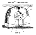
- FIGS. 8-15 are schematic views showing a novel BodyTomTM CT machine formed in accordance with the present invention.
- FIGS. 16-26 are schematic views showing another novel BodyTomTM CT machine also formed in accordance with the present invention.
- CereTom® CT machine 5 hereinafter sometimes referred to as the BodyTomTM CT machine, which can be used to scan the torso of a patient while the patient is supported on patient support 100 , and which can include a motorized drive for transporting the system between scanning locations.
- BodyTomTM CT machine 205 is preferably substantially the same as the aforementioned CereTom® CT machine 5 , except that (i) BodyTomTM CT machine 205 is scaled up in size so that central opening 220 of BodyTomTM CT machine 205 can receive the full body of a patient (and horizontally-extending surgical platform 105 ), and (ii) a bottom notch 280 is provided in skirt 275 of BodyTomTM CT machine 205 .
- Bottom notch 280 is sized, relative to horizontally-extending base 110 of patient support 100 , so that BodyTomTM CT machine 205 can encompass the patient's torso (and surgical platform 105 ) in its central opening 220 during scanning, with horizontally-extending base 110 being received in bottom notch 280 of BodyTomTM CT machine 205 .
- bottom notch 280 has a width 282 ( FIG. 11 ) which is wider that the width 127 ( FIG. 5 ) of horizontally-extending base 110
- bottom notch 280 has a height 283 ( FIG. 11 ) which is taller than the height 128 ( FIG. 5 ) of horizontally-extending base 110 .
- bottom notch 280 has a width 282 of approximately 34.1 inches and a height 283 of approximately 6.8 inches.
- the ground-engaging elements of the machine's transport assembly e.g., the various casters and centipede belt drives previously discussed
- bottom notch 280 clear to receive the base of a patient support.
- FIGS. 12-15 show BodyTomTM CT machine 205 in various positions relative to patient support 110 and the patient.
- BodyTomTM CT machine 205 has its central opening 220 and its bottom notch 280 configured so that BodyTomTM CT machine 205 can encompass the patient's torso (and surgical platform 105 ) in central opening 220 during scanning, with horizontally-extending base 110 being received in bottom notch 280 of BodyTomTM CT machine 205 .
- casters 62 of gross movement mechanism 55 can be replaced with an alternative gross movement mechanism, e.g., wheels, rolling balls, etc.
- centipede belt drives 63 of fine movement mechanism 60 can be replaced with an alternative floor crawler mechanism, e.g., a tracked floor crawler mechanism, a wheeled floor crawler mechanism, etc.
- a video camera/video screen system can be provided on BodyTomTM CT machine 205 in order to assist the operator in safely navigating around obstacles which might otherwise be obstructed from the view of the operator when transporting and/or positioning the machine. This feature can be particularly important in view of the increased size of BodyTomTM CT machine 205 .
- video cameras and video screens are provided on each end of BodyTomTM CT machine 205 , so that the operator can maneuver the machine from either end.
- video cameras 285 A, 285 B and video screens 290 A, 290 B may be provided, with the operator viewing the output of video camera 285 A on video screen 290 B or the output of video camera 285 B on video screen 290 A.
- video screens 290 A, 290 B are also used to provide output to the operator when BodyTomTM CT machine 205 is being used in scanning mode, set-up mode, etc.
- batteries 70 can be Lithium-Ion batteries.
- the BodyTomTM CT machine 205 comprises a motorized drive.
- the BodyTomTM CT machine 205 is preferably substantially the same as the aforementioned CereTom® CT machine 5 , except that the casters 62 of gross movement mechanism 55 ( FIG. 3 ) are replaced by a pair of drive wheels 291 ( FIGS. 16 and 17 ) and a pair of casters 292 , and means are provided for permitting a user to selectively power each of the drive wheels 291 forwardly or rearwardly so as to steerably drive the BodyTomTM CT machine 205 . Furthermore, the centipede belt drives 63 of fine movement mechanism 60 ( FIG.
- FIG. 3 may comprise a pair of parallel drive belts 60 A, 60 B disposed in side-by-side relation ( FIG. 17 ), so that a pair of parallel drive belts 60 A, 60 B are disposed on each side of the machine ( FIG. 17 ), rather than a single drive belt 60 being disposed on each side of the machine ( FIG. 3 ).
- a drive bar 293 is provided to control the application of power to each of the drive wheels 291 .
- drive bar 293 is configured so that when the right side 293 A of drive bar 293 is pressed forwardly (i.e., toward the body of the BodyTomTM CT machine 205 ), drive wheel 291 A is caused to rotate forwardly, and when the right side 293 A of drive bar 293 is pulled rearwardly (i.e., away from the body of the BodyTomTM CT machine 205 ), drive wheel 291 A is caused to rotate rearwardly.
- drive wheel 291 B when the left side 293 B of drive bar 293 is pressed forwardly (i.e., toward the body of the BodyTomTM CT machine 205 ), drive wheel 291 B is caused to rotate forwardly, and when the left side 293 B of drive bar 293 is pulled rearwardly (i.e., away from the body of the BodyTomTM CT machine 205 ), drive wheel 291 B is caused to rotate rearwardly.
- the right side 293 A of drive bar 293 , and the left side 293 B of drive bar 293 may be moved (i) forwardly together, in which case drive wheels 291 A, 291 B move forwardly together, (ii) rearwardly together, in which case drive wheels 291 A, 291 B move rearwardly together, or (iii) in opposite directions, in which case drive wheels 291 A, 291 B move oppositely to one another.
- the amount of power applied to the drive wheels 291 is proportional to the amount of force applied to each end of drive bar 293 , and power to drive wheels 291 is terminated if no force is being applied to drive bar 293 .
- a counterpart drive bar 294 may be provided on the opposite end of the BodyTomTM CT machine 205 ( FIGS. 23-26 ), whereby to allow the machine to be “driven” from either end of the machine.
- BodyTomTM CT machine 205 includes the aforementioned video cameras 285 A, 285 B and the aforementioned video screens 290 A, 290 B ( FIGS. 18-21 and 23 - 26 ).
- BodyTomTM CT machine 205 is preferably configured so that when the machine is being operated in scanning mode, video screens 290 A, 290 B provide information and/or images to the operator of the machine.
- BodyTomTM CT machine 205 is preferably also configured so when BodyTomTM CT machine 205 is being driven by drive wheels 291 , video camera 285 A is automatically activated and its acquired image displayed on display screen 290 B, and video camera 285 B is automatically activated and its acquired image displayed on display screen 290 A.
- display screens 290 A, 290 B are preferably located at about eye level to an operator who has their hands placed on drive bar 287 or drive bar 294 .
- BodyTomTM CT machine 205 can be easily and safely moved in any direction, since it allows the operator to drive the machine from either end of the machine via drive bars 287 , 294 , and see what is immediately ahead of the leading end of the machine via video cameras 285 A, 285 B and display screens 290 A, 290 B.
- the present invention is not limited to use in medical applications or, indeed, to use with CT machines.
- the present invention may be used in connection with CT machines used for non-medical applications, e.g., with CT machines used to scan inanimate objects which are to be supported on an object support which needs to be encompassed by the CT machine (e.g., in the center opening of the CT machine and the bottom notch of the CT machine).
- the present invention may be used with non-CT-type scanning systems.
- the present invention may be used in conjunction with SPECT machines, MRI machines, PET machines, X-ray machines, etc., i.e., wherever the scanning machine must accommodate portions of a support within the scanning machine during scanning.
Abstract
An imaging system including a scanner for scanning an object and creating an image of the same; and a transport mechanism mounted to the scanner for moving the scanner, wherein the transport mechanism includes a gross movement mechanism for transporting the scanner between scanning locations; and a fine movement mechanism for moving the scanner precisely, relative to the object being scanned, during scanning of the object; wherein the gross movement mechanism comprises at least one motorized wheel.
Description
This patent application is a continuation of pending prior U.S. patent application Ser. No. 13/304,006, filed Nov. 23, 2011 by Eric Bailey et al. for ANATOMICAL IMAGING SYSTEM WITH CENTIPEDE SCANNING DRIVE, BOTTOM NOTCH TO ACCOMMODATE BASE OF PATIENT SUPPORT, AND MOTORIZED DRIVE FOR TRANSPORTING THE SYSTEM BETWEEN SCANNING LOCATIONS, which in turn:
(i) is a continuation-in-part of prior U.S. patent application Ser. No. 12/655,360, filed Dec. 29, 2009 by Andrew P. Tybinkowski et al. for ANATOMICAL IMAGING SYSTEM WITH CENTIPEDE BELT DRIVE, which is a continuation of prior U.S. patent application Ser. No. 11/706,133, filed Feb. 13, 2007 by Andrew P. Tybinkowski et al. for ANATOMICAL IMAGING SYSTEM WITH CENTIPEDE BELT DRIVE, which is a continuation of prior U.S. patent application Ser. No. 11/193,941, filed Jul. 29, 2005 by Andrew P. Tybinkowski et al. for ANATOMICAL IMAGING SYSTEM WITH CENTIPEDE BELT DRIVE, which claims benefit of (a) prior U.S. Provisional Patent Application Ser. No. 60/670,164, filed Apr. 11, 2005 by Andrew P. Tybinkowski et al. for ANATOMICAL IMAGING SYSTEM WITH CENTIPEDE DRIVE; and (b) prior U.S. Provisional Patent Application Ser. No. 60/593,001, filed Jul. 30, 2004 by Bernard Gordon et al. for ANATOMICAL SCANNING SYSTEM;
(ii) is a continuation-in-part of pending prior U.S. patent application Ser. No. 13/250,754, filed Sep. 30, 2011 by Eric Bailey et al. for ANATOMICAL IMAGING SYSTEM WITH CENTIPEDE BELT DRIVE AND BOTTOM NOTCH TO ACCOMMODATE BASE OF PATIENT SUPPORT, which claims benefit of prior U.S. Provisional Patent Application Ser. No. 61/388,487, filed Sep. 30, 2010 by Eric Bailey et al. for ANATOMICAL IMAGING SYSTEM WITH CENTIPEDE BELT DRIVE AND BOTTOM NOTCH TO ACCOMMODATE BASE OF PATIENT SUPPORT; and
(iii) claims benefit of prior U.S. Provisional Patent Application Ser. No. 61/417,032, filed Nov. 24, 2010 by Eric Bailey et al. for ANATOMICAL IMAGING SYSTEM WITH CENTIPEDE BELT DRIVE AND BOTTOM NOTCH TO ACCOMMODATE BASE OF PATIENT SUPPORT.
The above-identified patent applications are hereby incorporated herein by reference.
This invention relates to imaging systems in general, and more particularly to anatomical imaging systems.
Looking first at FIGS. 1-4 , there is shown a CereTom® CT machine 5 made by Neurologica Corp. of Danvers, Mass. CereTom® CT machine 5 is a relatively small, mobile CT machine which is intended to be brought to the patient so that the patient can be scanned at the patient's current location, rather than requiring that the patient be transported to the location of a CT machine, so as to facilitate more rapid and/or more convenient scanning of the patient.
CereTom® CT machine 5 generally comprises a torus 10 which is supported by a base 15. A center opening 20 is formed in torus 10. Center opening 20 receives the patient anatomy which is to be scanned by CereTom® CT machine 5. Inasmuch as CereTom® CT machine 5 is designed to be as small and mobile as possible, and inasmuch as CereTom® CT machine 5 is intended to be used extensively for stroke diagnosis applications, center opening 20 is configured to be just slightly larger than the head of a patient.
Looking next at FIG. 3 , torus 10 of CereTom® CT machine 5 generally comprises an X-ray tube assembly 25, an X-ray detector assembly 30, and a rotating drum assembly 35. X-ray tube assembly 25 and X-ray detector assembly 30 are mounted to rotating drum assembly 35 in diametrically-opposed relation, such that the X-ray beam 40 (generated by X-ray tube assembly 25 and detected by X-ray detector assembly 30) is passed through the patient anatomy which is disposed in center opening 20. Significantly, inasmuch as X-ray tube assembly 25 and X-ray detector assembly 30 are mounted on rotating drum assembly 35 so that they rotate concentrically about center opening 20, X-ray beam 40 will be passed through the patient's anatomy along a full range of radial positions, so as to enable CereTom® CT machine 5 to create a visual rendition of the scanned anatomy using computerized tomography algorithms of the sort well known in the art.
Still looking at FIG. 3 , the various electronic hardware and software for controlling the operation of X-ray tube assembly 25, X-ray detector assembly 30, and rotating drum assembly 35, as well as for processing the acquired scan data so as to generate the desired visual rendition of the scanned anatomy, are located in torus 10 and/or base 15.
Looking next at FIGS. 3 and 4 , base 15 of CereTom® CT machine 5 comprises a transport assembly 50 for moving the CereTom® CT machine 5 relative to the patient. More particularly, transport assembly 50 comprises a gross movement mechanism 55 for moving CereTom® CT machine 5 relatively quickly across room distances, and a fine movement mechanism 60 for moving CereTom® CT machine 5 precisely, relative to the patient, during scanning. Gross movement mechanism 55 preferably comprises a plurality of casters 62, and fine movement mechanism 60 preferably comprises a plurality of centipede belt drives 63. Hydraulic apparatus 65 permits either gross movement mechanism 55, or fine movement mechanism 60, to be engaged with the floor, whereby to facilitate appropriate movement of CereTom® CT machine 5. Thus, with CereTom® CT machine 5, the CT machine may be pre-positioned in an “out of the way” location in an emergency room and then, when a patient requires scanning, the patient may be scanned right at their bedside, by quickly moving the CT machine to the patient's bedside on gross movement mechanism 55 (e.g., casters 62), and thereafter moving the machine during scanning on fine movement mechanism 60 (e.g., centipede belt drives 63).
Looking again at FIG. 3 , base 15 also includes other system components in addition to those discussed above, e.g., batteries 70 for powering various electrical components of CereTom® CT machine 5, etc.
As noted above, the various components of CereTom® CT machine 5 are engineered so as to provide a relatively small and mobile CT machine. As a result, CereTom® CT machine 5 is particularly well suited for use in stroke diagnosis applications. More particularly, since CereTom® CT machine 5 is constructed so as to be a small, mobile unit, it can be pre-positioned in the emergency room of a hospital and then quickly moved to the bedside of a patient when scanning is required, rather than requiring the patient to be transported to a radiology department for scanning. Furthermore, the patient can be scanned while remaining on their hospital bed or gurney, since CereTom® CT machine 5 moves relative to the patient during scanning. This is extremely beneficial, since it eliminates transport delays and hence significantly reduces the time needed to scan the patient, which can be extremely important in timely diagnosing a potential stroke victim.
Further details regarding the construction and use of CereTom® CT machine 5 are disclosed in U.S. Pat. Nos. 7,175,347, 7,637,660, 7,568,836, 7,963,696, 7,438,471, 7,397,895, 7,396,160 and 7,736,056, which patents are hereby incorporated herein by reference.
In practice, CereTom® CT machine 5 has proven to be highly effective in the timely diagnosis of potential stroke victims. In addition, CereTom® CT machine 5 has also proven to be highly effective in other head scanning applications, in the scanning of limbs (e.g., arms and/or hands, legs and/or feet), and in scanning infants and small toddlers (e.g., those capable of fitting within center opening 20). Furthermore, CereTom® CT machine 5 has also proven highly effective in veterinarian applications (e.g., to scan the leg and/or hoof of a horse).
Significantly, in view of the relatively small size and high mobility of CereTom® CT machine 5, CT scanning has been conducted in a wide range of different locations, e.g., in emergency rooms for stroke diagnosis, in operating rooms for neurosurgical applications, in veterinary clinics for animal treatment, etc.
In view of the substantial success of CereTom® CT machine 5, it has now been desired to increase the size of CereTom® CT machine 5 so that it can be used for full body scanning, e.g., such as during a spinal procedure in an operating room. To this end, it is necessary for CereTom® CT machine 5 to be scaled up in size so that the diameter of center opening 20 is large enough to receive both the torso of the patient and the surgical platform needed to support the patient during the surgical procedure. However, in this respect, it must also be appreciated that additional changes must be made to CereTom® CT machine 5 in order to permit the aforementioned full body scanning in an operating room setting.
More particularly, in FIGS. 5-7 there is shown a typical patient support 100 for supporting a patient during a surgical procedure. Patient support 100 generally comprises a horizontally-extending surgical platform 105 for receiving and supporting the patient. Horizontally-extending surgical platform 105 is supported above the ground by a horizontally-extending base 110 and a vertically-extending riser 115. It will be appreciated that horizontally-extending surgical platform 105 essentially comprises a cantilever beam arrangement. It will also be appreciated that, in view of the substantial length of horizontally-extending surgical platform 105, and also the substantial weight associated with horizontally-extending surgical platform 105 (particularly when a patient is lying on surgical platform 105), horizontally-extending base 110 must generally have a substantial length and a substantial mass in order to prevent patient support 100 from tipping over. In other words, in practice, the “head end” 120 of horizontally-extending base 110 must extend a substantial distance away from the “foot end” 125 of horizontally-extending base 110, and horizontally-extending base 110 must have a substantial mass in order to prevent patient support 100 from tipping over. This substantial mass for horizontally-extending base 110 is typically provided by giving the base a relatively substantial width 127 and a relatively substantial height 128.
Unfortunately, and as seen in FIGS. 1-4 , base 15 of CereTom® CT machine 5 has a bottom skirt 75 which is disposed very close to the floor when CereTom® CT machine 5 is in its “scanning mode”, i.e., when CereTom® CT machine 5 is supported by, and moves on, its fine movement mechanism 60 (e.g., centipede belt drives 63). As a result, simply scaling an existing CereTom® CT machine 5 upward in size to the point where central opening 20 can receive the torso of a patient (and surgical platform 105) will not result in a scanning machine which is capable of scanning the patient on patient support 100, since skirt 75 of base 15 of CereTom® CT machine 5 would engage the “head end” 120 of horizontally-extending base 110 of patient support 100 before CereTom® CT machine 5 can encompass the patient's torso (and surgical platform 105) in its central opening 20. In this respect it should be appreciated that the bottom of skirt 75 of CereTom® CT machine 5 is substantially even about the perimeter of the machine (i.e., the gap between the bottom of skirt 75 and the floor is substantially uniform about the entire perimeter of the machine). Furthermore, it should also be appreciated that with CereTom® CT machine 5, the bottom of skirt 75 is disposed relatively close to the surface of the floor, in order to prevent the feet of personnel from getting under the machine and in order to protect the components of the machine from collisions with objects, dust, etc. In fact, when CereTom® CT machine 5 is supported on its centipede belt drives 63, the bottom of skirt 75 sits approximately 2.2 inches above the surface of the floor.
Thus there is a need for a new and improved form of CereTom® CT machine 5 which can be used to scan the torso of a patient while the patient is supported on patient support 100.
In addition to the foregoing, as noted above, in order to enable a CereTom® CT machine 5 to be used for full body scanning, it is necessary to significantly increase the size of the machine. This can make it difficult to manually move the enlarged machine on its gross movement mechanism 55 (e.g., casters 62).
Thus there is a need to provide a new and improved form of CereTom® CT machine 5 which includes a motorized drive for transporting the system between scanning locations.
These and other objects of the present invention are addressed by the provision and use of a new and improved form of CereTom® CT machine 5, which can be used to scan the torso of a patient while the patient is supported on patient support 100, and which can include a motorized drive for transporting the system between scanning locations.
In one preferred form of the invention, there is provided an imaging system comprising:
a scanner for scanning an object and creating an image of the same; and
a transport mechanism mounted to the scanner for moving the scanner, wherein the transport mechanism comprises:
-
- a gross movement mechanism for transporting the scanner between scanning locations; and
- a fine movement mechanism for moving the scanner precisely, relative to the object being scanned, during scanning of the object;
wherein the gross movement mechanism comprises at least one motorized wheel.
In another preferred form of the invention, there is provided a method for imaging an object, the method comprising:
providing an imaging system comprising:
-
- a scanner for scanning an object and creating an image of the same; and
- a transport mechanism mounted to the scanner for moving the scanner, wherein the transport mechanism comprises:
- a gross movement mechanism for transporting the scanner between scanning locations; and
- a fine movement mechanism for moving the scanner precisely, relative to the object being scanned, during scanning of the object;
- wherein the gross movement mechanism comprises at least one motorized wheel;
moving the scanner on the gross movement mechanism; and
scanning the object while moving the scanner precisely, relative to the object, with the fine movement mechanism.
These and other objects and features of the present invention will be more fully disclosed or rendered obvious by the following detailed description of the preferred embodiments of the invention, which is to be considered together with the accompanying drawings wherein like numbers refer to like parts and further wherein:
In accordance with the present invention, there is now provided a new and improved form of CereTom® CT machine 5, hereinafter sometimes referred to as the BodyTom™ CT machine, which can be used to scan the torso of a patient while the patient is supported on patient support 100, and which can include a motorized drive for transporting the system between scanning locations.
More particularly, and looking now at FIGS. 8-11 , there is shown a BodyTom™ CT machine 205 formed in accordance with the present invention. In one preferred form of the invention, BodyTom™ CT machine 205 is preferably substantially the same as the aforementioned CereTom® CT machine 5, except that (i) BodyTom™ CT machine 205 is scaled up in size so that central opening 220 of BodyTom™ CT machine 205 can receive the full body of a patient (and horizontally-extending surgical platform 105), and (ii) a bottom notch 280 is provided in skirt 275 of BodyTom™ CT machine 205. Bottom notch 280 is sized, relative to horizontally-extending base 110 of patient support 100, so that BodyTom™ CT machine 205 can encompass the patient's torso (and surgical platform 105) in its central opening 220 during scanning, with horizontally-extending base 110 being received in bottom notch 280 of BodyTom™ CT machine 205. In other words, bottom notch 280 has a width 282 (FIG. 11 ) which is wider that the width 127 (FIG. 5 ) of horizontally-extending base 110, and bottom notch 280 has a height 283 (FIG. 11 ) which is taller than the height 128 (FIG. 5 ) of horizontally-extending base 110. By way of example but not limitation, in one preferred form of the present invention, bottom notch 280 has a width 282 of approximately 34.1 inches and a height 283 of approximately 6.8 inches. Thus, where the lowest point of skirt 275 sits approximately 2.2 inches above the surface of the floor when BodyTom™ CT machine 205 is supported on its centipede belt drives, the top of bottom notch 280 sits approximately 9.0 inches from the surface of the floor. It will, of course, also be appreciated that the ground-engaging elements of the machine's transport assembly (e.g., the various casters and centipede belt drives previously discussed) are located outboard of bottom notch 280, in order to keep bottom notch 280 clear to receive the base of a patient support.
See FIGS. 12-15 , which show BodyTom™ CT machine 205 in various positions relative to patient support 110 and the patient. In particular, note how BodyTom™ CT machine 205 has its central opening 220 and its bottom notch 280 configured so that BodyTom™ CT machine 205 can encompass the patient's torso (and surgical platform 105) in central opening 220 during scanning, with horizontally-extending base 110 being received in bottom notch 280 of BodyTom™ CT machine 205.
If desired, casters 62 of gross movement mechanism 55 can be replaced with an alternative gross movement mechanism, e.g., wheels, rolling balls, etc. Furthermore, if desired, centipede belt drives 63 of fine movement mechanism 60 can be replaced with an alternative floor crawler mechanism, e.g., a tracked floor crawler mechanism, a wheeled floor crawler mechanism, etc.
Also, if desired, a video camera/video screen system can be provided on BodyTom™ CT machine 205 in order to assist the operator in safely navigating around obstacles which might otherwise be obstructed from the view of the operator when transporting and/or positioning the machine. This feature can be particularly important in view of the increased size of BodyTom™ CT machine 205. In one preferred form of the invention, video cameras and video screens are provided on each end of BodyTom™ CT machine 205, so that the operator can maneuver the machine from either end. By way of example but not limitation, video cameras 285A, 285B and video screens 290A, 290B may be provided, with the operator viewing the output of video camera 285A on video screen 290B or the output of video camera 285B on video screen 290A. Thus, the operator can maneuver the BodyTom™ CT machine 205 from the trailing end of the machine while still seeing whatever may be in front of the leading end of the machine. In one preferred form of the invention, video screens 290A, 290B are also used to provide output to the operator when BodyTom™ CT machine 205 is being used in scanning mode, set-up mode, etc.
Furthermore, if desired, batteries 70 can be Lithium-Ion batteries.
In one preferred form of the present invention, the BodyTom™ CT machine 205 comprises a motorized drive.
More particularly, in this form of the invention, and looking now at FIGS. 16-26 , the BodyTom™ CT machine 205 is preferably substantially the same as the aforementioned CereTom® CT machine 5, except that the casters 62 of gross movement mechanism 55 (FIG. 3 ) are replaced by a pair of drive wheels 291 (FIGS. 16 and 17) and a pair of casters 292, and means are provided for permitting a user to selectively power each of the drive wheels 291 forwardly or rearwardly so as to steerably drive the BodyTom™ CT machine 205. Furthermore, the centipede belt drives 63 of fine movement mechanism 60 (FIG. 3 ) may comprise a pair of parallel drive belts 60A, 60B disposed in side-by-side relation (FIG. 17 ), so that a pair of parallel drive belts 60A, 60B are disposed on each side of the machine (FIG. 17 ), rather than a single drive belt 60 being disposed on each side of the machine (FIG. 3 ).
More particularly, and looking now at FIGS. 18-21 , a drive bar 293 is provided to control the application of power to each of the drive wheels 291. Preferably, drive bar 293 is configured so that when the right side 293A of drive bar 293 is pressed forwardly (i.e., toward the body of the BodyTom™ CT machine 205), drive wheel 291A is caused to rotate forwardly, and when the right side 293A of drive bar 293 is pulled rearwardly (i.e., away from the body of the BodyTom™ CT machine 205), drive wheel 291A is caused to rotate rearwardly. Correspondingly, when the left side 293B of drive bar 293 is pressed forwardly (i.e., toward the body of the BodyTom™ CT machine 205), drive wheel 291B is caused to rotate forwardly, and when the left side 293B of drive bar 293 is pulled rearwardly (i.e., away from the body of the BodyTom™ CT machine 205), drive wheel 291B is caused to rotate rearwardly. Significantly, the right side 293A of drive bar 293, and the left side 293B of drive bar 293, may be moved (i) forwardly together, in which case drive wheels 291A, 291B move forwardly together, (ii) rearwardly together, in which case drive wheels 291A, 291B move rearwardly together, or (iii) in opposite directions, in which case drive wheels 291A, 291B move oppositely to one another.
Preferably, the amount of power applied to the drive wheels 291 is proportional to the amount of force applied to each end of drive bar 293, and power to drive wheels 291 is terminated if no force is being applied to drive bar 293.
Thus, it will be seen that, to move the BodyTom™ CT machine 205 forwardly, the right side 293A of drive bar 293, and the left side 293B of drive bar 293, are both pushed forwardly (FIG. 22A ); to move the BodyTom™ CT machine 205 rearwardly, the right side 293A of drive bar 293, and the left side 293B of drive bar 293, are both pulled rearwardly (FIG. 22B ); to turn the BodyTom™ CT machine 205 to the left, the right side 293A of drive bar 293 may be pressed forwardly and the left side 293B of drive bar 293 may be pulled rearwardly (FIG. 22C ); and to turn the BodyTom™ CT machine 205 to the right, the left side 293B of drive bar 293 may be pressed forwardly and the right side 293A may be pulled rearwardly (FIG. 22D ).
If desired, a counterpart drive bar 294 may be provided on the opposite end of the BodyTom™ CT machine 205 (FIGS. 23-26 ), whereby to allow the machine to be “driven” from either end of the machine.
Preferably, BodyTom™ CT machine 205 includes the aforementioned video cameras 285A, 285B and the aforementioned video screens 290A, 290B (FIGS. 18-21 and 23-26). BodyTom™ CT machine 205 is preferably configured so that when the machine is being operated in scanning mode, video screens 290A, 290B provide information and/or images to the operator of the machine. BodyTom™ CT machine 205 is preferably also configured so when BodyTom™ CT machine 205 is being driven by drive wheels 291, video camera 285A is automatically activated and its acquired image displayed on display screen 290B, and video camera 285B is automatically activated and its acquired image displayed on display screen 290A. As a result, the operator is able to see where BodyTom™ CT machine 205 is going when it is being driven via drive bar 287 or drive bar 294. To this end, display screens 290A, 290B are preferably located at about eye level to an operator who has their hands placed on drive bar 287 or drive bar 294.
As a result of the foregoing constructions, BodyTom™ CT machine 205 can be easily and safely moved in any direction, since it allows the operator to drive the machine from either end of the machine via drive bars 287, 294, and see what is immediately ahead of the leading end of the machine via video cameras 285A, 285B and display screens 290A, 290B.
It should be appreciated that the present invention is not limited to use in medical applications or, indeed, to use with CT machines. Thus, for example, the present invention may be used in connection with CT machines used for non-medical applications, e.g., with CT machines used to scan inanimate objects which are to be supported on an object support which needs to be encompassed by the CT machine (e.g., in the center opening of the CT machine and the bottom notch of the CT machine). Furthermore, the present invention may be used with non-CT-type scanning systems. Thus, for example, the present invention may be used in conjunction with SPECT machines, MRI machines, PET machines, X-ray machines, etc., i.e., wherever the scanning machine must accommodate portions of a support within the scanning machine during scanning.
It will be appreciated that still further embodiments of the present invention will be apparent to those skilled in the art in view of the present disclosure. It is to be understood that the present invention is by no means limited to the particular constructions herein disclosed and/or shown in the drawings, but also comprises any modifications or equivalents within the scope of the invention.
Claims (28)
1. Apparatus for imaging an object, the apparatus comprising:
a CT machine configured to move on a surface, the CT machine comprising a leading end and a trailing end, wherein the CT machine comprises a camera and a viewing screen, wherein the output of the camera is displayed on the viewing screen, and further wherein the camera is disposed on the leading end of the CT machine so as to capture an image of the space ahead of the leading end of the CT machine during movement of the CT machine across the surface;
wherein the CT machine is further configured to image the object while the object is supported on a support, the support comprising a base for positioning on a surface, wherein the object and the support are stationary relative to the surface, and further wherein the CT machine is adapted to move relative to the surface, and hence relative to the object and to the support, during imaging;
the CT machine comprising a housing having a bottom notch sized to accommodate the base of the support, whereby to allow the base of the support to extend into the housing during imaging.
2. Apparatus according to claim 1 wherein the viewing screen is disposed on the trailing end of the CT machine.
3. Apparatus according to claim 1 wherein the CT machine comprises a second camera and a second viewing screen, wherein the output of the camera is displayed on the second viewing screen and the output of the second camera is displayed on the viewing screen, and further wherein the camera and the second viewing screen are disposed on the leading end of the CT machine and the second camera and the viewing screen are disposed on the trailing end of the CT machine.
4. Apparatus according to claim 1 wherein the apparatus is configured to image anatomy.
5. Apparatus according to claim 1 wherein the apparatus is configured to image an inanimate object.
6. Apparatus according to claim 1 wherein the apparatus comprises a gross movement mechanism for moving the CT machine across the surface when not imaging, and further wherein the gross movement mechanism comprises at least one wheel.
7. Apparatus according to claim 1 wherein the apparatus comprises a gross movement mechanism for moving the CT machine across the surface when not imaging, and further wherein the gross movement mechanism is powered by a motor.
8. Apparatus according to claim 1 wherein the apparatus comprises a fine movement mechanism for moving the CT machine precisely, relative to the object, during imaging, and further wherein the fine movement mechanism comprises at least one centipede belt drive.
9. Apparatus according to claim 8 wherein the fine movement mechanism comprises a pair of centipede belt drives.
10. Apparatus according to claim 1 wherein the surface comprises the floor of a room.
11. Apparatus according to claim 1 wherein the surface comprises the floor of a vehicle.
12. Apparatus according to claim 1 wherein the support comprises a horizontally-extending base, a vertically-extending riser and a horizontally-extending platform, and further wherein the horizontally-extending platform is cantilevered over at least a portion of the horizontally-extending base.
13. Apparatus according to claim 12 wherein the horizontally-extending platform is sized to receive the body of a patient.
14. Apparatus according to claim 1 wherein the apparatus comprises a fine movement mechanism for moving the CT machine precisely, relative to the object, during imaging, and wherein the fine movement mechanism comprises a pair of centipede belt drives, and further wherein one centipede belt drive is disposed on either side of the bottom notch.
15. A method for moving an imaging device on a surface, the method comprising:
providing a CT machine comprising a leading end and a trailing end, wherein the CT machine comprises a camera and a viewing screen, wherein the output of the camera is displayed on the viewing screen, and further wherein the camera is disposed on the leading end of the CT machine so as to capture an image of the space ahead of the leading end of the CT machine;
wherein the CT machine is further configured to image the object while the object is supported on a support, the support comprising a base for positioning on a surface, wherein the object and the support are stationary relative to the surface, and further wherein the CT machine is adapted to move relative to the surface, and hence relative to the object and to the support, during imaging;
the CT machine comprising a housing having a bottom notch sized to accommodate the base of the support, whereby to allow the base of the support to extend into the housing during imaging; and
moving the CT machine across the surface while capturing an image of the space ahead of the leading end of the CT machine.
16. A method according to claim 15 wherein the surface comprises the floor of a room.
17. A method according to claim 15 wherein the surface comprises the floor of a vehicle.
18. A method according to claim 15 wherein the support comprises a horizontally-extending base, a vertically-extending riser and a horizontally-extending platform, and further wherein the horizontally-extending platform is cantilevered over at least a portion of the horizontally-extending base.
19. A method according to claim 18 wherein the horizontally-extending platform is sized to receive the body of a patient.
20. A method according to claim 15 wherein the apparatus comprises a fine movement mechanism for moving the CT machine precisely, relative to the object, during imaging, and wherein the fine movement mechanism comprises a pair of centipede belt drives, and further wherein one centipede belt drive is disposed on either side of the bottom notch.
21. A method according to claim 15 wherein the viewing screen is disposed on the trailing end of the CT machine.
22. A method according to claim 15 wherein the CT machine comprises a second camera and a second viewing screen, wherein the output of the camera is displayed on the second viewing screen and the output of the second camera is displayed on the viewing screen, and further wherein the camera and the second viewing screen are disposed on the leading end of the CT machine and the second camera and the viewing screen are disposed on the trailing end of the CT machine.
23. A method according to claim 15 wherein the CT machine is configured to image anatomy.
24. A method according to claim 15 wherein the CT machine is configured to image an inanimate object.
25. A method according to claim 15 wherein the CT machine comprises a gross movement mechanism for moving the CT machine across the surface when not imaging, and further wherein the gross movement mechanism comprises at least one wheel.
26. A method according to claim 15 wherein the CT machine comprises a gross movement mechanism for moving the CT machine across the surface when not imaging, and further wherein the gross movement mechanism is powered by a motor.
27. A method according to claim 15 wherein the CT machine comprises a fine movement mechanism for moving the CT machine precisely, relative to the object, during imaging, and further wherein the fine movement mechanism comprises at least one centipede belt drive.
28. A method according to claim 27 wherein the fine movement mechanism comprises a pair of centipede belt drives.
Priority Applications (2)
| Application Number | Priority Date | Filing Date | Title |
|---|---|---|---|
| US14/541,247 US9561010B2 (en) | 2004-07-30 | 2014-11-14 | Anatomical imaging system with centipede scanning drive, bottom notch to accommodate base of patient support, and motorized drive for transporting the system between scanning locations |
| US15/426,580 US10178981B2 (en) | 2004-07-30 | 2017-02-07 | Anatomical imaging system with centipede scanning drive, bottom notch to accommodate base of patient support, and motorized drive for transporting the system between scanning locations |
Applications Claiming Priority (10)
| Application Number | Priority Date | Filing Date | Title |
|---|---|---|---|
| US59300104P | 2004-07-30 | 2004-07-30 | |
| US67016405P | 2005-04-11 | 2005-04-11 | |
| US11/193,941 US7175347B2 (en) | 2004-07-30 | 2005-07-29 | Anatomical imaging system with centipede belt drive |
| US11/706,133 US7637660B2 (en) | 2004-07-30 | 2007-02-13 | Anatomical imaging system with centipede belt drive |
| US12/655,360 US8251584B2 (en) | 2004-07-30 | 2009-12-29 | Anatomical imaging system with centipede belt drive |
| US38848710P | 2010-09-30 | 2010-09-30 | |
| US41703210P | 2010-11-24 | 2010-11-24 | |
| US13/250,754 US8971482B2 (en) | 2004-07-30 | 2011-09-30 | Anatomical imaging system with centipede belt drive and bottom notch to accommodate base of patient support |
| US13/304,006 US8888364B2 (en) | 2004-07-30 | 2011-11-23 | Anatomical imaging system with centipede scanning drive, bottom notch to accommodate base of patient support, and motorized drive for transporting the system between scanning locations |
| US14/541,247 US9561010B2 (en) | 2004-07-30 | 2014-11-14 | Anatomical imaging system with centipede scanning drive, bottom notch to accommodate base of patient support, and motorized drive for transporting the system between scanning locations |
Related Parent Applications (1)
| Application Number | Title | Priority Date | Filing Date |
|---|---|---|---|
| US13/304,006 Continuation US8888364B2 (en) | 2004-07-30 | 2011-11-23 | Anatomical imaging system with centipede scanning drive, bottom notch to accommodate base of patient support, and motorized drive for transporting the system between scanning locations |
Related Child Applications (1)
| Application Number | Title | Priority Date | Filing Date |
|---|---|---|---|
| US15/426,580 Continuation US10178981B2 (en) | 2004-07-30 | 2017-02-07 | Anatomical imaging system with centipede scanning drive, bottom notch to accommodate base of patient support, and motorized drive for transporting the system between scanning locations |
Publications (2)
| Publication Number | Publication Date |
|---|---|
| US20150196263A1 US20150196263A1 (en) | 2015-07-16 |
| US9561010B2 true US9561010B2 (en) | 2017-02-07 |
Family
ID=46162240
Family Applications (3)
| Application Number | Title | Priority Date | Filing Date |
|---|---|---|---|
| US13/304,006 Active 2026-05-18 US8888364B2 (en) | 2004-07-30 | 2011-11-23 | Anatomical imaging system with centipede scanning drive, bottom notch to accommodate base of patient support, and motorized drive for transporting the system between scanning locations |
| US14/541,247 Active US9561010B2 (en) | 2004-07-30 | 2014-11-14 | Anatomical imaging system with centipede scanning drive, bottom notch to accommodate base of patient support, and motorized drive for transporting the system between scanning locations |
| US15/426,580 Active US10178981B2 (en) | 2004-07-30 | 2017-02-07 | Anatomical imaging system with centipede scanning drive, bottom notch to accommodate base of patient support, and motorized drive for transporting the system between scanning locations |
Family Applications Before (1)
| Application Number | Title | Priority Date | Filing Date |
|---|---|---|---|
| US13/304,006 Active 2026-05-18 US8888364B2 (en) | 2004-07-30 | 2011-11-23 | Anatomical imaging system with centipede scanning drive, bottom notch to accommodate base of patient support, and motorized drive for transporting the system between scanning locations |
Family Applications After (1)
| Application Number | Title | Priority Date | Filing Date |
|---|---|---|---|
| US15/426,580 Active US10178981B2 (en) | 2004-07-30 | 2017-02-07 | Anatomical imaging system with centipede scanning drive, bottom notch to accommodate base of patient support, and motorized drive for transporting the system between scanning locations |
Country Status (1)
| Country | Link |
|---|---|
| US (3) | US8888364B2 (en) |
Cited By (1)
| Publication number | Priority date | Publication date | Assignee | Title |
|---|---|---|---|---|
| US20170367668A1 (en) * | 2004-07-30 | 2017-12-28 | Neurologica Corp. | Anatomical imaging system with centipede scanning drive, bottom notch to accommodate base of patient support, and motorized drive for transporting the system between scanning locations |
Families Citing this family (34)
| Publication number | Priority date | Publication date | Assignee | Title |
|---|---|---|---|---|
| US11944469B2 (en) | 2010-03-12 | 2024-04-02 | Mobius Imaging Llc | Caster system for mobile apparatus |
| US11278461B2 (en) | 2010-07-07 | 2022-03-22 | Aspect Imaging Ltd. | Devices and methods for a neonate incubator, capsule and cart |
| US10499830B2 (en) | 2010-07-07 | 2019-12-10 | Aspect Imaging Ltd. | Premature neonate life support environmental chamber for use in MRI/NMR devices |
| IL226488A (en) * | 2013-05-21 | 2016-07-31 | Aspect Imaging Ltd | Cradle for neonates |
| US10076266B2 (en) | 2010-07-07 | 2018-09-18 | Aspect Imaging Ltd. | Devices and methods for a neonate incubator, capsule and cart |
| US9737273B2 (en) | 2011-04-07 | 2017-08-22 | Mobius Imaging, Llc | Mobile X-ray imaging system |
| US10987068B2 (en) | 2012-06-14 | 2021-04-27 | Mobius Imaging Llc | Multi-directional x-ray imaging system |
| US10835190B2 (en) | 2013-03-15 | 2020-11-17 | Mobius Imaging, Llc | Mobile X-ray imaging system |
| EP2967470B1 (en) | 2013-03-15 | 2020-10-21 | Mobius Imaging, Llc | Caster system for mobile apparatus |
| JP6345485B2 (en) * | 2013-05-29 | 2018-06-20 | キヤノンメディカルシステムズ株式会社 | Bed apparatus, X-ray CT apparatus, and medical image diagnostic apparatus |
| EP3041451A4 (en) | 2013-09-02 | 2017-05-03 | Aspect Imaging Ltd. | A passive thermo-regulated neonatal transport incubator |
| JP1524788S (en) * | 2014-11-25 | 2015-06-01 | ||
| JP1553963S (en) * | 2015-10-29 | 2016-07-19 | ||
| US10492756B2 (en) | 2016-03-29 | 2019-12-03 | NeuroLogica Corporation, a subsidiary of Samsung Electronics Co., Ltd. | Correction for drive, tilt, and scanning-speed errors in imaging systems |
| US10224135B2 (en) | 2016-08-08 | 2019-03-05 | Aspect Imaging Ltd. | Device, system and method for obtaining a magnetic measurement with permanent magnets |
| US11287497B2 (en) | 2016-08-08 | 2022-03-29 | Aspect Imaging Ltd. | Device, system and method for obtaining a magnetic measurement with permanent magnets |
| US10980692B2 (en) | 2016-08-29 | 2021-04-20 | Mobius Imaging, Llc | Table system for medical imaging |
| USD839431S1 (en) * | 2016-09-14 | 2019-01-29 | Synaptive Medical (Barbados) Inc. | MRI scanner |
| US11369326B2 (en) | 2017-02-28 | 2022-06-28 | Neurologica Corporation | Mobile anatomical imaging system with improved movement system comprising liddiard wheels |
| WO2018160730A1 (en) * | 2017-02-28 | 2018-09-07 | Neurologica Corporation | Mobile anatomical imaging system with improved movement system |
| US11052016B2 (en) | 2018-01-18 | 2021-07-06 | Aspect Imaging Ltd. | Devices, systems and methods for reducing motion artifacts during imaging of a neonate |
| US11197643B2 (en) | 2018-03-16 | 2021-12-14 | Mobius Imaging, Llc | Medical x-ray imaging systems and methods |
| US11717252B2 (en) | 2018-08-03 | 2023-08-08 | NeuroLogica Corporation, a subsidiary of Samsung Electronics Co., Ltd. | AI-based rendered volume auto-correction for fixed and mobile x-ray imaging modalities and other imaging modalities |
| USD903119S1 (en) * | 2018-12-11 | 2020-11-24 | Our United Corporation | Accessories of radiotherapy equipment |
| USD903117S1 (en) * | 2018-12-11 | 2020-11-24 | Our United Corporation | Accessories of radiotherapy equipment |
| USD903118S1 (en) * | 2018-12-11 | 2020-11-24 | Our United Corporation | Accessories of radiotherapy equipment |
| KR102175457B1 (en) * | 2019-02-27 | 2020-11-06 | 원광대학교산학협력단 | Computer tomography apparatus with three-phase power supply connector and steering interface module |
| JP1650139S (en) * | 2019-04-05 | 2020-01-20 | ||
| USD940868S1 (en) * | 2019-05-06 | 2022-01-11 | Siemens Healthcare Gmbh | Electromedical device |
| USD940869S1 (en) * | 2019-08-30 | 2022-01-11 | Siemens Healthcare Gmbh | Medical imaging apparatus |
| USD931463S1 (en) * | 2019-11-22 | 2021-09-21 | Siemens Healthcare Gmbh | Medical imaging apparatus |
| CN116322520A (en) * | 2020-10-19 | 2023-06-23 | 伊美姬艾利斯有限责任公司 | Radiation imaging apparatus with improved functionality |
| USD1001284S1 (en) | 2020-11-17 | 2023-10-10 | Siemens Healthcare Gmbh | Medical imaging device |
| USD965076S1 (en) * | 2021-05-06 | 2022-09-27 | Haibin Zhang | Toy CT machine |
Citations (48)
| Publication number | Priority date | Publication date | Assignee | Title |
|---|---|---|---|---|
| US2765860A (en) | 1953-10-12 | 1956-10-09 | Robert E Church | Selective wheeled or endless belt supports for self-propelled vehicles |
| US3603975A (en) | 1969-04-01 | 1971-09-07 | Gordon Eng Co | Device for analog to digital conversion or digital to analog conversion |
| US3775612A (en) | 1970-12-14 | 1973-11-27 | Monroe X Ray Co | Pipeline x-ray inspection machine |
| US3904878A (en) | 1972-09-01 | 1975-09-09 | Xmas Inc | Pipeline crawler type x-ray machine |
| US4006359A (en) | 1970-10-12 | 1977-02-01 | Abs Worldwide Technical Services, Inc. | Pipeline crawler |
| US4131802A (en) | 1976-06-28 | 1978-12-26 | Ohio-Nuclear, Inc. | Automatic patient table having means for transporting patient along a table |
| CN1037450A (en) | 1988-04-13 | 1989-11-29 | 模拟公司 | X-ray tomography apparatus with position sensor |
| US4928283A (en) | 1988-02-26 | 1990-05-22 | Analogic Corporation | X-ray tomography apparatus |
| US5389101A (en) | 1992-04-21 | 1995-02-14 | University Of Utah | Apparatus and method for photogrammetric surgical localization |
| US5448607A (en) | 1994-02-08 | 1995-09-05 | Analogic Corporation | X-ray tomography system with gantry pivot and translation control |
| WO1998000681A1 (en) | 1996-07-03 | 1998-01-08 | Advanced Research And Applications Corporation | Straddle inspection system |
| US5736821A (en) | 1992-12-28 | 1998-04-07 | Tokyo Gas Co., Ltd. | Intrapipe work robot apparatus and method of measuring position of intrapipe work robot |
| US5867553A (en) | 1995-11-02 | 1999-02-02 | Analogic Corporation | Computed tomography scanner with reduced power x-ray source |
| US5887047A (en) | 1997-04-09 | 1999-03-23 | Analogic Corporation | Parallel processing architecture for computed tomography scanning system using non-parallel slices |
| JPH11164829A (en) | 1997-12-03 | 1999-06-22 | Toshiba Corp | Frame movable helical scanning ct apparatus |
| US5982843A (en) | 1997-10-10 | 1999-11-09 | Analogic Corporation | Closed loop air conditioning system for a computed tomography scanner |
| US6108396A (en) | 1998-02-11 | 2000-08-22 | Analogic Corporation | Apparatus and method for correcting object density in computed tomography data |
| US6144180A (en) | 1999-07-09 | 2000-11-07 | Chen; Chun-Ta | Mobile robot |
| US6256404B1 (en) | 1997-10-10 | 2001-07-03 | Analogic Corporation | Computed tomography scanning apparatus and method using adaptive reconstruction window |
| US6285028B1 (en) | 1998-06-02 | 2001-09-04 | Kabushiki Kaisha Toshiba | Semiconductor radiation detector and nuclear medicine diagnostic apparatus |
| US20020035317A1 (en) | 2000-08-04 | 2002-03-21 | Photonify Technologies | Optical imaging system with movable scanning unit |
| JP2002085394A (en) | 2000-09-14 | 2002-03-26 | Ge Medical Systems Global Technology Co Llc | Gantry-moved type ct scanner |
| US6374937B1 (en) | 1998-05-29 | 2002-04-23 | John Galando | Motorized support for imaging means and methods of manufacture and use thereof |
| US6396902B2 (en) | 2000-07-31 | 2002-05-28 | Analogic Corporation | X-ray collimator |
| US6459923B1 (en) | 2000-11-22 | 2002-10-01 | General Electric Company | Intervention bed for a medical imaging device |
| US20030072613A1 (en) | 2001-10-17 | 2003-04-17 | Colvard John Charles | Adjusting arrangement for steerable transport assembly for self-propelled construction vehicle |
| US20030095635A1 (en) | 2001-11-19 | 2003-05-22 | Ge Yokogawa Medical Systems, Limited | Gantry system and X-ray CT system |
| JP2003190149A (en) | 2001-12-18 | 2003-07-08 | Ge Medical Systems Global Technology Co Llc | Medical diagnostic system, diagnostic method and apparatus |
| US20030147490A1 (en) | 2002-02-05 | 2003-08-07 | Kimberly-Clark Worldwide, Inc. | Method and apparatus for examining absorbent articles |
| US20030206609A1 (en) | 2002-05-01 | 2003-11-06 | Koninklijke Philips Electronics N.V. | Method and apparatus for computed tomography imaging |
| US6705758B1 (en) | 1999-06-30 | 2004-03-16 | Instrumntarium Corp. | Steering arrangement for mobile x-ray apparatus |
| US6813374B1 (en) | 2001-04-25 | 2004-11-02 | Analogic Corporation | Method and apparatus for automatic image quality assessment |
| US6857778B2 (en) | 1999-07-23 | 2005-02-22 | Inki Mun | Surgical scanning system and process for use thereof |
| US6959068B1 (en) | 1999-02-26 | 2005-10-25 | Siemens Aktiengesellschaft | Computed tomography apparatus |
| US20050284672A1 (en) | 2002-05-21 | 2005-12-29 | Renk Aktiengesellschaft | Electric steering and drive system for a vehicle with wheel side steering system |
| US20060083354A1 (en) * | 2004-07-30 | 2006-04-20 | Tybinkowski Andrew P | Anatomical imaging system with centipede belt drive |
| US20070183589A1 (en) | 2004-07-30 | 2007-08-09 | Tybinkowski Andrew B | Mobile computerized tomography (CT) imaging system with frame/bearing/drum construction |
| US20070183588A1 (en) | 2004-07-30 | 2007-08-09 | Bailey Eric M | Mobile Computerized Tomography (CT) imaging system with cordless and wireless capabilities |
| US20070195938A1 (en) | 2004-07-30 | 2007-08-23 | Bailey Eric M | Mobile computerized tomography (CT) imaging system with off-center x-ray beam |
| US7319738B2 (en) | 2004-10-08 | 2008-01-15 | General Electric Company | Delivering X-ray systems to pipe installations |
| US7338207B2 (en) | 2002-08-21 | 2008-03-04 | Medtronic Navigation, Inc. | Gantry positioning apparatus for X-ray imaging |
| US7396160B2 (en) | 2004-07-30 | 2008-07-08 | Neurologica Corp. | Computerized tomography (CT) imaging system with monoblock X-ray tube assembly |
| US7736056B2 (en) | 2004-07-30 | 2010-06-15 | Neurologica Corp. | X-ray transparent bed and gurney extender for use with mobile computerized tomography (CT) imaging systems |
| US20100172468A1 (en) | 2009-01-05 | 2010-07-08 | Mobius Imaging, Llc | Mobile medical imaging system and methods |
| US20110222667A1 (en) * | 2010-03-12 | 2011-09-15 | Gregerson Eugene A | Drive system for imaging device |
| US20110228910A1 (en) | 2010-03-19 | 2011-09-22 | Gregerson Eugene A | Diagnostic imaging apparatus with airflow cooling system |
| US20120256099A1 (en) | 2011-04-07 | 2012-10-11 | Mobius Imaging, Llc | Mobile x-ray imaging system |
| US8971482B2 (en) * | 2004-07-30 | 2015-03-03 | Neurologica Corp. | Anatomical imaging system with centipede belt drive and bottom notch to accommodate base of patient support |
Family Cites Families (5)
| Publication number | Priority date | Publication date | Assignee | Title |
|---|---|---|---|---|
| JPS62179434A (en) | 1986-01-31 | 1987-08-06 | 横河メディカルシステム株式会社 | Tomographic image pickup apparatus |
| US5426683A (en) | 1994-03-14 | 1995-06-20 | Oec Medical Systems, Inc. | One piece C-arm for X-ray diagnostic equipment |
| DE19505276A1 (en) | 1995-02-16 | 1996-08-29 | Siemens Ag | Computer tomography for use in operating theatre |
| US6199233B1 (en) | 1998-04-24 | 2001-03-13 | Allen Kantrowitz | Radiolucent table extension assembly |
| US8888364B2 (en) | 2004-07-30 | 2014-11-18 | Neurologica Corp. | Anatomical imaging system with centipede scanning drive, bottom notch to accommodate base of patient support, and motorized drive for transporting the system between scanning locations |
-
2011
- 2011-11-23 US US13/304,006 patent/US8888364B2/en active Active
-
2014
- 2014-11-14 US US14/541,247 patent/US9561010B2/en active Active
-
2017
- 2017-02-07 US US15/426,580 patent/US10178981B2/en active Active
Patent Citations (58)
| Publication number | Priority date | Publication date | Assignee | Title |
|---|---|---|---|---|
| US2765860A (en) | 1953-10-12 | 1956-10-09 | Robert E Church | Selective wheeled or endless belt supports for self-propelled vehicles |
| US3603975A (en) | 1969-04-01 | 1971-09-07 | Gordon Eng Co | Device for analog to digital conversion or digital to analog conversion |
| US4006359A (en) | 1970-10-12 | 1977-02-01 | Abs Worldwide Technical Services, Inc. | Pipeline crawler |
| US3775612A (en) | 1970-12-14 | 1973-11-27 | Monroe X Ray Co | Pipeline x-ray inspection machine |
| US3904878A (en) | 1972-09-01 | 1975-09-09 | Xmas Inc | Pipeline crawler type x-ray machine |
| US4131802A (en) | 1976-06-28 | 1978-12-26 | Ohio-Nuclear, Inc. | Automatic patient table having means for transporting patient along a table |
| US4928283A (en) | 1988-02-26 | 1990-05-22 | Analogic Corporation | X-ray tomography apparatus |
| CN1037450A (en) | 1988-04-13 | 1989-11-29 | 模拟公司 | X-ray tomography apparatus with position sensor |
| US5389101A (en) | 1992-04-21 | 1995-02-14 | University Of Utah | Apparatus and method for photogrammetric surgical localization |
| US5736821A (en) | 1992-12-28 | 1998-04-07 | Tokyo Gas Co., Ltd. | Intrapipe work robot apparatus and method of measuring position of intrapipe work robot |
| US5448607A (en) | 1994-02-08 | 1995-09-05 | Analogic Corporation | X-ray tomography system with gantry pivot and translation control |
| US5867553A (en) | 1995-11-02 | 1999-02-02 | Analogic Corporation | Computed tomography scanner with reduced power x-ray source |
| WO1998000681A1 (en) | 1996-07-03 | 1998-01-08 | Advanced Research And Applications Corporation | Straddle inspection system |
| US5887047A (en) | 1997-04-09 | 1999-03-23 | Analogic Corporation | Parallel processing architecture for computed tomography scanning system using non-parallel slices |
| US5982843A (en) | 1997-10-10 | 1999-11-09 | Analogic Corporation | Closed loop air conditioning system for a computed tomography scanner |
| US6256404B1 (en) | 1997-10-10 | 2001-07-03 | Analogic Corporation | Computed tomography scanning apparatus and method using adaptive reconstruction window |
| JPH11164829A (en) | 1997-12-03 | 1999-06-22 | Toshiba Corp | Frame movable helical scanning ct apparatus |
| US6212251B1 (en) | 1997-12-03 | 2001-04-03 | Kabushiki Kaisha Toshiba | Helical scanning type X-ray CT apparatus with movable gantry |
| US6108396A (en) | 1998-02-11 | 2000-08-22 | Analogic Corporation | Apparatus and method for correcting object density in computed tomography data |
| US6374937B1 (en) | 1998-05-29 | 2002-04-23 | John Galando | Motorized support for imaging means and methods of manufacture and use thereof |
| US6285028B1 (en) | 1998-06-02 | 2001-09-04 | Kabushiki Kaisha Toshiba | Semiconductor radiation detector and nuclear medicine diagnostic apparatus |
| US6959068B1 (en) | 1999-02-26 | 2005-10-25 | Siemens Aktiengesellschaft | Computed tomography apparatus |
| US6705758B1 (en) | 1999-06-30 | 2004-03-16 | Instrumntarium Corp. | Steering arrangement for mobile x-ray apparatus |
| US6144180A (en) | 1999-07-09 | 2000-11-07 | Chen; Chun-Ta | Mobile robot |
| US6857778B2 (en) | 1999-07-23 | 2005-02-22 | Inki Mun | Surgical scanning system and process for use thereof |
| US6396902B2 (en) | 2000-07-31 | 2002-05-28 | Analogic Corporation | X-ray collimator |
| US20020035317A1 (en) | 2000-08-04 | 2002-03-21 | Photonify Technologies | Optical imaging system with movable scanning unit |
| JP2002085394A (en) | 2000-09-14 | 2002-03-26 | Ge Medical Systems Global Technology Co Llc | Gantry-moved type ct scanner |
| US6459923B1 (en) | 2000-11-22 | 2002-10-01 | General Electric Company | Intervention bed for a medical imaging device |
| US6813374B1 (en) | 2001-04-25 | 2004-11-02 | Analogic Corporation | Method and apparatus for automatic image quality assessment |
| US20030072613A1 (en) | 2001-10-17 | 2003-04-17 | Colvard John Charles | Adjusting arrangement for steerable transport assembly for self-propelled construction vehicle |
| US20030095635A1 (en) | 2001-11-19 | 2003-05-22 | Ge Yokogawa Medical Systems, Limited | Gantry system and X-ray CT system |
| JP2003190149A (en) | 2001-12-18 | 2003-07-08 | Ge Medical Systems Global Technology Co Llc | Medical diagnostic system, diagnostic method and apparatus |
| US20030147490A1 (en) | 2002-02-05 | 2003-08-07 | Kimberly-Clark Worldwide, Inc. | Method and apparatus for examining absorbent articles |
| US20030206609A1 (en) | 2002-05-01 | 2003-11-06 | Koninklijke Philips Electronics N.V. | Method and apparatus for computed tomography imaging |
| US20050284672A1 (en) | 2002-05-21 | 2005-12-29 | Renk Aktiengesellschaft | Electric steering and drive system for a vehicle with wheel side steering system |
| US7338207B2 (en) | 2002-08-21 | 2008-03-04 | Medtronic Navigation, Inc. | Gantry positioning apparatus for X-ray imaging |
| US7438471B2 (en) | 2004-07-30 | 2008-10-21 | Neurologica Corp. | Mobile computerized tomography (CT) imaging system with frame/bearing/drum construction |
| US7736056B2 (en) | 2004-07-30 | 2010-06-15 | Neurologica Corp. | X-ray transparent bed and gurney extender for use with mobile computerized tomography (CT) imaging systems |
| US20070183588A1 (en) | 2004-07-30 | 2007-08-09 | Bailey Eric M | Mobile Computerized Tomography (CT) imaging system with cordless and wireless capabilities |
| US20070195938A1 (en) | 2004-07-30 | 2007-08-23 | Bailey Eric M | Mobile computerized tomography (CT) imaging system with off-center x-ray beam |
| US8971482B2 (en) * | 2004-07-30 | 2015-03-03 | Neurologica Corp. | Anatomical imaging system with centipede belt drive and bottom notch to accommodate base of patient support |
| US7175347B2 (en) | 2004-07-30 | 2007-02-13 | Neurologica, Corp. | Anatomical imaging system with centipede belt drive |
| US7397895B2 (en) | 2004-07-30 | 2008-07-08 | Neurologica Corp. | Mobile computerized tomography (CT) imaging system with cordless and wireless capabilities |
| US7396160B2 (en) | 2004-07-30 | 2008-07-08 | Neurologica Corp. | Computerized tomography (CT) imaging system with monoblock X-ray tube assembly |
| US20060083354A1 (en) * | 2004-07-30 | 2006-04-20 | Tybinkowski Andrew P | Anatomical imaging system with centipede belt drive |
| US7568836B2 (en) | 2004-07-30 | 2009-08-04 | Neurologica Corp. | Mobile computerized tomography (CT) imaging system with off-center x-ray beam |
| US7637660B2 (en) | 2004-07-30 | 2009-12-29 | Neurologica Corp. | Anatomical imaging system with centipede belt drive |
| US20070183589A1 (en) | 2004-07-30 | 2007-08-09 | Tybinkowski Andrew B | Mobile computerized tomography (CT) imaging system with frame/bearing/drum construction |
| US8251584B2 (en) | 2004-07-30 | 2012-08-28 | Neurologica Corp. | Anatomical imaging system with centipede belt drive |
| US7963696B2 (en) | 2004-07-30 | 2011-06-21 | Neurologica Corp. | Mobile computerized tomography (CT) imaging system with off-center X-ray beam |
| US7319738B2 (en) | 2004-10-08 | 2008-01-15 | General Electric Company | Delivering X-ray systems to pipe installations |
| US8118488B2 (en) | 2009-01-05 | 2012-02-21 | Mobius Imaging, Llc | Mobile medical imaging system and methods |
| US20100172468A1 (en) | 2009-01-05 | 2010-07-08 | Mobius Imaging, Llc | Mobile medical imaging system and methods |
| US20120330087A1 (en) | 2009-01-05 | 2012-12-27 | Mobius Imaging, Llc | Mobile medical imaging system and methods |
| US20110222667A1 (en) * | 2010-03-12 | 2011-09-15 | Gregerson Eugene A | Drive system for imaging device |
| US20110228910A1 (en) | 2010-03-19 | 2011-09-22 | Gregerson Eugene A | Diagnostic imaging apparatus with airflow cooling system |
| US20120256099A1 (en) | 2011-04-07 | 2012-10-11 | Mobius Imaging, Llc | Mobile x-ray imaging system |
Cited By (2)
| Publication number | Priority date | Publication date | Assignee | Title |
|---|---|---|---|---|
| US20170367668A1 (en) * | 2004-07-30 | 2017-12-28 | Neurologica Corp. | Anatomical imaging system with centipede scanning drive, bottom notch to accommodate base of patient support, and motorized drive for transporting the system between scanning locations |
| US10178981B2 (en) * | 2004-07-30 | 2019-01-15 | Neurologica Corp. | Anatomical imaging system with centipede scanning drive, bottom notch to accommodate base of patient support, and motorized drive for transporting the system between scanning locations |
Also Published As
| Publication number | Publication date |
|---|---|
| US20150196263A1 (en) | 2015-07-16 |
| US10178981B2 (en) | 2019-01-15 |
| US20170367668A1 (en) | 2017-12-28 |
| US8888364B2 (en) | 2014-11-18 |
| US20120140899A1 (en) | 2012-06-07 |
Similar Documents
| Publication | Publication Date | Title |
|---|---|---|
| US10178981B2 (en) | Anatomical imaging system with centipede scanning drive, bottom notch to accommodate base of patient support, and motorized drive for transporting the system between scanning locations | |
| US8971482B2 (en) | Anatomical imaging system with centipede belt drive and bottom notch to accommodate base of patient support | |
| US20240050051A1 (en) | Cantilevered X-Ray CT System For Multi-Axis Imaging | |
| US11602318B2 (en) | Mobile anatomical imaging system with improved movement system | |
| US5499415A (en) | Stabilized, cantilevered, patient trauma table system | |
| JP5372461B2 (en) | Portable tomography diagnostic system with an open gantry | |
| US20160278724A1 (en) | Robotic multi-mode radiological scanning system and method | |
| US10667772B2 (en) | Radiation-irradiation device | |
| JPH08206104A (en) | Device and method for medical diagnostic image pickup | |
| US9572544B2 (en) | Deployable guard for mobile x-ray system | |
| WO2008035828A1 (en) | Dental complex imaging system | |
| JP2008253762A (en) | Portable digital tomosynthesis imaging system and method | |
| US10136866B2 (en) | Radiation irradiation device | |
| US11612371B2 (en) | Radiation tracking for portable fluoroscopy x-ray imaging system | |
| US20180192979A1 (en) | Transport assisting method and transport assisting device for radiation-irradiation device, and radiographic imaging apparatus | |
| US20180146940A1 (en) | Radiation-irradiation device | |
| US11369326B2 (en) | Mobile anatomical imaging system with improved movement system comprising liddiard wheels | |
| JP4186014B2 (en) | Portable recumbent panoramic X-ray imaging system | |
| US20230181126A1 (en) | Mobile ct imaging system comprising a mobile ct imaging machine with an on-board digital radiography imager and/or an on-board ultrasound imager | |
| US20240016457A1 (en) | Method and apparatus for automatically aligning a scanner with an object to be scanned | |
| US20230181127A1 (en) | Mobile ct imaging system comprising a mobile ct imaging machine with an on-board motorized bed and/or an on-board ultrasound imager |
Legal Events
| Date | Code | Title | Description |
|---|---|---|---|
| AS | Assignment |
Owner name: NEUROLOGICA CORP., MASSACHUSETTS Free format text: ASSIGNMENT OF ASSIGNORS INTEREST;ASSIGNORS:BAILEY, ERIC M.;TYBINKOWSKI, ANDREW P.;REEL/FRAME:039600/0444 Effective date: 20120119 |
|
| STCF | Information on status: patent grant |
Free format text: PATENTED CASE |
|
| MAFP | Maintenance fee payment |
Free format text: PAYMENT OF MAINTENANCE FEE, 4TH YEAR, LARGE ENTITY (ORIGINAL EVENT CODE: M1551); ENTITY STATUS OF PATENT OWNER: LARGE ENTITY Year of fee payment: 4 |