US9559379B2 - Heater - Google Patents
Heater Download PDFInfo
- Publication number
- US9559379B2 US9559379B2 US14/662,902 US201514662902A US9559379B2 US 9559379 B2 US9559379 B2 US 9559379B2 US 201514662902 A US201514662902 A US 201514662902A US 9559379 B2 US9559379 B2 US 9559379B2
- Authority
- US
- United States
- Prior art keywords
- fuel
- fuel cell
- cell stack
- oxidizing agent
- supply conduit
- Prior art date
- Legal status (The legal status is an assumption and is not a legal conclusion. Google has not performed a legal analysis and makes no representation as to the accuracy of the status listed.)
- Active, expires
Links
- 239000000446 fuel Substances 0.000 claims abstract description 463
- 230000000712 assembly Effects 0.000 claims abstract description 114
- 238000000429 assembly Methods 0.000 claims abstract description 114
- 239000007800 oxidant agent Substances 0.000 claims description 44
- 230000015572 biosynthetic process Effects 0.000 claims description 23
- 230000005611 electricity Effects 0.000 claims description 9
- 239000012530 fluid Substances 0.000 claims description 7
- 238000006243 chemical reaction Methods 0.000 claims description 5
- 239000000126 substance Substances 0.000 claims description 4
- 238000005755 formation reaction Methods 0.000 description 22
- 239000000463 material Substances 0.000 description 8
- 239000000203 mixture Substances 0.000 description 8
- 238000002485 combustion reaction Methods 0.000 description 7
- 238000010438 heat treatment Methods 0.000 description 6
- 229910001220 stainless steel Inorganic materials 0.000 description 4
- 239000010935 stainless steel Substances 0.000 description 4
- 239000007789 gas Substances 0.000 description 3
- 238000004519 manufacturing process Methods 0.000 description 3
- 238000007789 sealing Methods 0.000 description 3
- 239000004215 Carbon black (E152) Substances 0.000 description 2
- 230000006835 compression Effects 0.000 description 2
- 238000007906 compression Methods 0.000 description 2
- 229930195733 hydrocarbon Natural products 0.000 description 2
- 150000002430 hydrocarbons Chemical class 0.000 description 2
- 239000007788 liquid Substances 0.000 description 2
- 239000002915 spent fuel radioactive waste Substances 0.000 description 2
- UFHFLCQGNIYNRP-UHFFFAOYSA-N Hydrogen Chemical compound [H][H] UFHFLCQGNIYNRP-UHFFFAOYSA-N 0.000 description 1
- 230000003197 catalytic effect Effects 0.000 description 1
- 239000000919 ceramic Substances 0.000 description 1
- 229910021525 ceramic electrolyte Inorganic materials 0.000 description 1
- 239000003245 coal Substances 0.000 description 1
- 239000004020 conductor Substances 0.000 description 1
- 239000000470 constituent Substances 0.000 description 1
- 230000029087 digestion Effects 0.000 description 1
- -1 for example Substances 0.000 description 1
- 238000002309 gasification Methods 0.000 description 1
- 239000001257 hydrogen Substances 0.000 description 1
- 229910052739 hydrogen Inorganic materials 0.000 description 1
- 239000002184 metal Substances 0.000 description 1
- 230000003647 oxidation Effects 0.000 description 1
- 238000007254 oxidation reaction Methods 0.000 description 1
- 238000009428 plumbing Methods 0.000 description 1
- 238000005067 remediation Methods 0.000 description 1
- 239000002689 soil Substances 0.000 description 1
- 239000007787 solid Substances 0.000 description 1
- 238000010257 thawing Methods 0.000 description 1
Images


Classifications
-
- H—ELECTRICITY
- H01—ELECTRIC ELEMENTS
- H01M—PROCESSES OR MEANS, e.g. BATTERIES, FOR THE DIRECT CONVERSION OF CHEMICAL ENERGY INTO ELECTRICAL ENERGY
- H01M8/00—Fuel cells; Manufacture thereof
- H01M8/24—Grouping of fuel cells, e.g. stacking of fuel cells
- H01M8/2465—Details of groupings of fuel cells
- H01M8/2484—Details of groupings of fuel cells characterised by external manifolds
- H01M8/2485—Arrangements for sealing external manifolds; Arrangements for mounting external manifolds around a stack
-
- E—FIXED CONSTRUCTIONS
- E21—EARTH DRILLING; MINING
- E21B—EARTH DRILLING, e.g. DEEP DRILLING; OBTAINING OIL, GAS, WATER, SOLUBLE OR MELTABLE MATERIALS OR A SLURRY OF MINERALS FROM WELLS
- E21B36/00—Heating, cooling, insulating arrangements for boreholes or wells, e.g. for use in permafrost zones
- E21B36/02—Heating, cooling, insulating arrangements for boreholes or wells, e.g. for use in permafrost zones using burners
-
- E—FIXED CONSTRUCTIONS
- E21—EARTH DRILLING; MINING
- E21B—EARTH DRILLING, e.g. DEEP DRILLING; OBTAINING OIL, GAS, WATER, SOLUBLE OR MELTABLE MATERIALS OR A SLURRY OF MINERALS FROM WELLS
- E21B43/00—Methods or apparatus for obtaining oil, gas, water, soluble or meltable materials or a slurry of minerals from wells
- E21B43/16—Enhanced recovery methods for obtaining hydrocarbons
- E21B43/24—Enhanced recovery methods for obtaining hydrocarbons using heat, e.g. steam injection
- E21B43/243—Combustion in situ
-
- H—ELECTRICITY
- H01—ELECTRIC ELEMENTS
- H01M—PROCESSES OR MEANS, e.g. BATTERIES, FOR THE DIRECT CONVERSION OF CHEMICAL ENERGY INTO ELECTRICAL ENERGY
- H01M8/00—Fuel cells; Manufacture thereof
- H01M8/04—Auxiliary arrangements, e.g. for control of pressure or for circulation of fluids
- H01M8/04007—Auxiliary arrangements, e.g. for control of pressure or for circulation of fluids related to heat exchange
-
- H—ELECTRICITY
- H01—ELECTRIC ELEMENTS
- H01M—PROCESSES OR MEANS, e.g. BATTERIES, FOR THE DIRECT CONVERSION OF CHEMICAL ENERGY INTO ELECTRICAL ENERGY
- H01M8/00—Fuel cells; Manufacture thereof
- H01M8/24—Grouping of fuel cells, e.g. stacking of fuel cells
- H01M8/2465—Details of groupings of fuel cells
- H01M8/2484—Details of groupings of fuel cells characterised by external manifolds
-
- H—ELECTRICITY
- H01—ELECTRIC ELEMENTS
- H01M—PROCESSES OR MEANS, e.g. BATTERIES, FOR THE DIRECT CONVERSION OF CHEMICAL ENERGY INTO ELECTRICAL ENERGY
- H01M8/00—Fuel cells; Manufacture thereof
- H01M8/24—Grouping of fuel cells, e.g. stacking of fuel cells
- H01M8/249—Grouping of fuel cells, e.g. stacking of fuel cells comprising two or more groupings of fuel cells, e.g. modular assemblies
-
- H—ELECTRICITY
- H01—ELECTRIC ELEMENTS
- H01M—PROCESSES OR MEANS, e.g. BATTERIES, FOR THE DIRECT CONVERSION OF CHEMICAL ENERGY INTO ELECTRICAL ENERGY
- H01M2250/00—Fuel cells for particular applications; Specific features of fuel cell system
- H01M2250/10—Fuel cells in stationary systems, e.g. emergency power source in plant
-
- Y—GENERAL TAGGING OF NEW TECHNOLOGICAL DEVELOPMENTS; GENERAL TAGGING OF CROSS-SECTIONAL TECHNOLOGIES SPANNING OVER SEVERAL SECTIONS OF THE IPC; TECHNICAL SUBJECTS COVERED BY FORMER USPC CROSS-REFERENCE ART COLLECTIONS [XRACs] AND DIGESTS
- Y02—TECHNOLOGIES OR APPLICATIONS FOR MITIGATION OR ADAPTATION AGAINST CLIMATE CHANGE
- Y02B—CLIMATE CHANGE MITIGATION TECHNOLOGIES RELATED TO BUILDINGS, e.g. HOUSING, HOUSE APPLIANCES OR RELATED END-USER APPLICATIONS
- Y02B90/00—Enabling technologies or technologies with a potential or indirect contribution to GHG emissions mitigation
- Y02B90/10—Applications of fuel cells in buildings
-
- Y—GENERAL TAGGING OF NEW TECHNOLOGICAL DEVELOPMENTS; GENERAL TAGGING OF CROSS-SECTIONAL TECHNOLOGIES SPANNING OVER SEVERAL SECTIONS OF THE IPC; TECHNICAL SUBJECTS COVERED BY FORMER USPC CROSS-REFERENCE ART COLLECTIONS [XRACs] AND DIGESTS
- Y02—TECHNOLOGIES OR APPLICATIONS FOR MITIGATION OR ADAPTATION AGAINST CLIMATE CHANGE
- Y02E—REDUCTION OF GREENHOUSE GAS [GHG] EMISSIONS, RELATED TO ENERGY GENERATION, TRANSMISSION OR DISTRIBUTION
- Y02E60/00—Enabling technologies; Technologies with a potential or indirect contribution to GHG emissions mitigation
- Y02E60/30—Hydrogen technology
- Y02E60/50—Fuel cells
-
- Y—GENERAL TAGGING OF NEW TECHNOLOGICAL DEVELOPMENTS; GENERAL TAGGING OF CROSS-SECTIONAL TECHNOLOGIES SPANNING OVER SEVERAL SECTIONS OF THE IPC; TECHNICAL SUBJECTS COVERED BY FORMER USPC CROSS-REFERENCE ART COLLECTIONS [XRACs] AND DIGESTS
- Y02—TECHNOLOGIES OR APPLICATIONS FOR MITIGATION OR ADAPTATION AGAINST CLIMATE CHANGE
- Y02P—CLIMATE CHANGE MITIGATION TECHNOLOGIES IN THE PRODUCTION OR PROCESSING OF GOODS
- Y02P90/00—Enabling technologies with a potential contribution to greenhouse gas [GHG] emissions mitigation
- Y02P90/40—Fuel cell technologies in production processes
Definitions
- the present invention relates to a heater which uses fuel cell stack assemblies as a source of heat; more particularly to such a heater which is positioned within a bore hole of an oil containing geological formation in order to liberate oil therefrom; and even more particularly to such a heater where each fuel cell stack assembly includes an orifice configured to provide a predetermined restriction to fuel or oxidizing agent supplied to the fuel cell stack assembly; and still even more particularly to such a heater where the fuel cell stack assemblies are arranged in fuel cell stack assembly groups such that the predetermined restriction for each fuel cell stack assembly group is unique in order to provide sufficient flow uniformity of fuel or oxidizing agent to each fuel cell stack assembly.
- Subterranean heaters have been used to heat subterranean geological formations in oil production, remediation of contaminated soils, accelerating digestion of landfills, thawing of permafrost, gasification of coal, as well as other uses.
- Some examples of subterranean heater arrangements include placing and operating electrical resistance heaters, microwave electrodes, gas-fired heaters or catalytic heaters in a bore hole of the formation to be heated.
- Other examples of subterranean heater arrangements include circulating hot gases or liquids through the formation to be heated, whereby the hot gases or liquids have been heated by a burner located on the surface of the earth. While these examples may be effective for heating the subterranean geological formation, they may be energy intensive to operate.
- U.S. Pat. Nos. 6,684,948 and 7,182,132 propose subterranean heaters which use fuel cells as a more energy efficient source of heat.
- the fuel cells are disposed in a heater housing which is positioned within the bore hole of the formation to be heated.
- the fuel cells convert chemical energy from a fuel into heat and electricity through a chemical reaction with an oxidizing agent.
- U.S. Pat. Nos. 6,684,948 and 7,182,132 illustrate strings of fuel cells that may be several hundred feet in length. Operation of the fuel cells requires fuel and air to be supplied to each of the fuel cells and spent fuel (anode exhaust) and spent air (cathode exhaust) must be exhausted from each of the fuel cells.
- a fuel supply conduit and an air supply conduit are provided such that each extends the entire length of the string of fuel cells to supply fuel and air to each of the fuel cells.
- Homogeneous distribution of fuel and air to each of the fuel cells may be problematic due to the length of the heaters which may be hundreds of feet long to in excess of one thousand feet, thereby resulting in pressure differentials from fuel cell to fuel cell along the length of the heater.
- the pressure differentials may result in variations in fuel and air flow to the fuel cells which may not be compatible with the desired operation of the heater.
- a heater assembly includes a plurality of fuel cell stack assemblies which each have a plurality of fuel cells which convert chemical energy from a fuel into heat and electricity through a chemical reaction with an oxidizing agent, each one of the plurality of fuel cell stack assemblies having a fuel cell manifold which 1) receives the fuel within a fuel inlet of the fuel cell manifold and distributes the fuel to the plurality of fuel cells and 2) receives the oxidizing agent within an oxidizing agent inlet of the fuel cell manifold and distributes the oxidizing agent to the plurality of fuel cells; a fuel supply conduit in fluid communication with the fuel cell manifold of the plurality of fuel cell stack assemblies, thereby communicating the fuel to the fuel inlet of the fuel cell manifold of the plurality of fuel cell stack assemblies an oxidizing agent supply conduit in fluid communication with the fuel cell manifold of the plurality of fuel cell stack assemblies, thereby communicating the oxidizing agent to the oxidizing agent inlet of the fuel cell manifold of the plurality of fuel cell stack assemblies.
- Each of the plurality of fuel cell stack assemblies includes an orifice disposed between the fuel supply conduit and the fuel inlet or between the oxidizing agent supply conduit and the oxidizing agent inlet.
- the plurality of fuel cell stack assemblies are arranged in fuel cell stack assembly groups such that the orifices of each of the fuel cell stack assembly groups are configured to provide a magnitude of restriction that is unique to their respective the fuel cell stack assembly group, thereby providing uniformity of flow of the fuel or the oxidizing agent to the plurality of fuel cell stack assemblies.
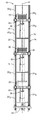
- FIG. 1 is an isometric partial cross-sectional view of a heater in accordance with the present invention
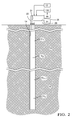
- FIG. 2 is a schematic view of a plurality of heaters of FIG. 1 shown in a bore hole of a geological formation;
- FIG. 3 is an end view of the heater of FIG. 1 ;
- FIG. 4 is an axial cross-sectional view of the heater of FIGS. 1 and 3 taken through section line 4 - 4 ;
- FIG. 5 is an axial cross-sectional view of the heater of FIGS. 1 and 3 taken through section line 5 - 5 ;
- FIG. 6 is an axial cross-sectional view of a fuel cell stack assembly of the heater of FIGS. 1 and 3 taken through section line 6 - 6 ;
- FIG. 7 is an elevation view of a fuel cell of the fuel cell stack assembly of FIG. 6 ;
- FIG. 8 is an enlargement of a portion of FIG. 7 ;
- FIG. 9 is an enlargement of a portion of FIG. 8 ;
- FIG. 10 is an isometric view of a flow director of a combustor of the heater of FIG. 1 ;
- FIG. 11 is a radial cross-section view the heater of FIG. 1 taken through section line 11 - 11 ;
- FIG. 12 is an isometric view of a baffle of the heater of FIG. 1 ;
- FIG. 13 is an enlargement of a portion of FIG. 4 showing adjacent fuel cell assemblies
- FIG. 14 is an enlargement of a portion of FIG. 5 showing adjacent fuel cell assemblies
- FIG. 15 is an enlargement of a portion of FIG. 13 ;
- FIG. 16 is an enlargement of a portion of FIG. 14 ;
- FIG. 17 is an alternative arrangement of FIG. 14 ;
- FIG. 18 is a schematic view of a plurality of fuel cell stack assembly groups shown in a bore hole of a geological formation
- FIG. 19 is an alternative arrangement of FIG. 15 ;
- FIG. 20 is an alternative arrangement of FIG. 16 .
- a heater 10 extending along a heater axis 12 is shown in accordance with the present invention.
- a plurality of heaters 10 1 , 10 2 , . . . 10 n ⁇ 1 , 10 n , where n is the total number of heaters 10 may be connected together end to end within a bore hole 14 of a formation 16 , for example, an oil containing geological formation, as shown in FIG. 2 in order to form a heater assembly 10 1 , 10 2 , . . . 10 n ⁇ 1 , 10 n .
- Bore hole 14 may be only a few feet deep; however, may typically be several hundred feet deep to in excess of one thousand feet deep and extends from a top end to a bottom end where the top end is considered the end of bore hole 14 where bore hole enters formation 16 . Consequently, the number of heaters 10 needed may range from 1 to several hundred. It should be noted that the oil containing geological formation may begin as deep as one thousand feet below the surface and consequently, heater 10 1 may be located sufficiently deep within bore hole 14 to be positioned near the beginning of the oil containing geological formation. When this is the case, units without active heating components may be positioned from the surface to heater 10 1 in order to provide plumbing, power leads, and instrumentation leads to support and supply fuel and air to heaters 10 1 to 10 n , as will be discussed later.
- Heater 10 generally includes a heater housing 18 extending along heater axis 12 , a plurality of fuel cell stack assemblies 20 located within said heater housing 18 such that each fuel cell stack assembly 20 is spaced axially apart from each other fuel cell stack assembly 20 , a first fuel supply conduit 22 and a second fuel supply conduit 24 for supplying fuel to fuel cell stack assemblies 20 , a first oxidizing agent supply conduit 26 and a second oxidizing agent supply conduit 28 ; hereinafter referred to as first air supply conduit 26 and second air supply conduit 28 ; for supplying an oxidizing agent, for example air, to fuel cell stack assemblies 20 , and a plurality of combustors 30 for combusting exhaust constituents produced by fuel cell stack assemblies 20 .
- heater 10 is illustrated with 3 fuel cell stack assemblies 20 within heater housing 18 , it should be understood that a lesser number or a greater number of fuel cell stack assemblies 20 may be included.
- the number of fuel cell stack assemblies 20 within heater housing 18 may be determined, for example only, by one or more of the following considerations: the length of heater housing 18 , the heat output capacity of each fuel cell stack assembly 20 , the desired density of fuel cell stack assemblies 20 (i.e. the number of fuel cell stack assemblies 20 per unit of length), and the desired heat output of heater 10 .
- the number of heaters 10 within bore hole 14 may be determined, for example only, by one or more of the following considerations: the depth of formation 16 which is desired to be heated, the location of oil within formation 16 , and the length of each heater 10 .
- Heater housing 18 may be substantially cylindrical and hollow. Heater housing 18 may support fuel cell stack assemblies 20 within heater housing 18 as will be described in greater detail later. Heater housing 18 of heater 10 x , where x is from 1 to n where n is the number of heaters 10 within bore hole 14 , may support heaters 10 x+1 to 10 n by heaters 10 x+1 to 10 n hanging from heater 10 n . Consequently, heater housing 18 may be made of a material that is substantially strong to accommodate the weight of fuel cell stack assemblies 20 and heaters 10 x+1 to 10 n . The material of heater housing 18 may also have properties to withstand the elevated temperatures, for example 600° C. to 900° C., as a result of the operation of fuel cell stack assemblies 20 and combustors 30 . For example only, heater housing 18 may be made of a 300 series stainless steel with a wall thickness of 3/16 of an inch.
- fuel cell stack assemblies 20 may be, for example only, solid oxide fuel cells which generally include a fuel cell manifold 32 , a plurality of fuel cell cassettes 34 (for clarity, only select fuel cell cassettes 34 have been labeled), and a fuel cell end cap 36 .
- Fuel cell cassettes 34 are stacked together between fuel cell manifold 32 and fuel cell end cap 36 and are held therebetween in compression with tie rods 38 .
- Each fuel cell stack assembly 20 may include, for example only, twenty to fifty fuel cell cassettes 34 .
- Each fuel cell cassette 34 includes a fuel cell 40 having an anode 42 and a cathode 44 separated by a ceramic electrolyte 46 .
- Each fuel cell 40 converts chemical energy from a fuel supplied to anode 42 into heat and electricity through a chemical reaction with air supplied to cathode 44 . Further features of fuel cell cassettes 34 and fuel cells 40 are disclosed in United States Patent Application Publication No. US 2012/0094201 to Haltiner, Jr. et al. which is incorporated herein by reference in its entirety.
- Fuel cell manifold 32 receives fuel, e.g. a hydrogen rich reformate which may be supplied from a fuel source illustrated as fuel reformer 48 , through a fuel inlet 50 from one or both of first fuel supply conduit 22 and second fuel supply conduit 24 and distributes the fuel to each of the fuel cell cassettes 34 .
- Fuel cell manifold 32 also receives an oxidizing agent, for example, air from an oxidizing agent source illustrated as an air supply 54 , through an air inlet 52 from one or both of first air supply conduit 26 and second air supply conduit 28 .
- Fuel cell manifold 32 also receives anode exhaust, i.e.
- spent fuel and excess fuel from fuel cells 40 which may comprise H 2 , CO, H 2 O, CO 2 , and N 2
- fuel cell manifold 32 also receives cathode exhaust, i.e. spent air and excess air from fuel cells 40 which may comprise O 2 (depleted compared to the air supplied through first air supply conduit 26 and second air supply conduit 28 ) and N 2
- cathode exhaust i.e. spent air and excess air from fuel cells 40 which may comprise O 2 (depleted compared to the air supplied through first air supply conduit 26 and second air supply conduit 28 ) and N 2
- cathode exhaust i.e. spent air and excess air from fuel cells 40 which may comprise O 2 (depleted compared to the air supplied through first air supply conduit 26 and second air supply conduit 28 ) and N 2
- cathode exhaust outlet 58 which is in fluid communication with a respective combustor 30 .
- combustor 30 may include an anode exhaust chamber 60 which receives anode exhaust from anode exhaust outlet 56 of fuel cell manifold 32 , a cathode exhaust chamber 62 which receives cathode exhaust from cathode exhaust outlet 58 of fuel cell manifold 32 , and a combustion chamber 64 which receives anode exhaust from anode exhaust chamber 60 and also receives cathode exhaust from cathode exhaust chamber 62 .
- Anode exhaust chamber 60 may be substantially cylindrical and connected to anode exhaust outlet 56 through an anode exhaust passage 66 which is coaxial with anode exhaust chamber 60 .
- Anode exhaust chamber 60 includes a plurality of anode exhaust mixing passages 68 which extend radially outward therefrom into combustion chamber 64 .
- Cathode exhaust chamber 62 may be substantially annular in shape and radially surrounding anode exhaust passage 66 in a coaxial relationship.
- Cathode exhaust chamber 62 includes a plurality of cathode exhaust mixing passages 70 extending axially therefrom into combustion chamber 64 .
- Cathode exhaust mixing passages 70 are located proximal to anode exhaust mixing passages 68 in order to allow anode exhaust gas exiting anode exhaust chamber 60 to impinge and mix with cathode exhaust exiting cathode exhaust chamber 62 .
- Combustion of the mixture of anode exhaust and cathode exhaust may occur naturally due to the temperature within combustion chamber 64 being equal to or greater than the autoignition temperature of the mixture of anode exhaust and cathode exhaust due to the operation of fuel cell stack assemblies 20 or the operation of a plurality of electric resistive heating elements (not shown) that may be used to begin operation of fuel cell stack assemblies 20 .
- anode exhaust is mixed with cathode exhaust within combustion chamber 64 and combusted therein to form a heated combustor exhaust comprising CO 2 , N 2 , O 2 , and H 2 O.
- Combustor 30 includes a combustor exhaust outlet 72 at the end of combustion chamber 64 for communicating the heated combustor exhaust from the combustor 30 to the interior volume of heater housing 18 thereby heating heater housing 18 and subsequently formation 16 .
- combustor 30 to generate heat for heating formation 16 allows fuel cell stack assemblies 20 to be operated is such a way that promotes long service life of fuel cell stack assemblies 20 while allowing heaters 10 to generate the necessary heat for heating formation 16 .
- each combustor 30 may include a flow director 74 and heater 10 may include a baffle 76 positioned radially between fuel cell stack assemblies 20 /combustors 30 and heater housing 18 in order increase the effectiveness of transferring heat from the heated combustor exhaust to heater housing 18 and subsequently to formation 16 .
- Baffle 76 is substantially cylindrical and coaxial with heater housing 18 , thereby defining a heat transfer channel 78 , which may be substantially annular in shape, radially between heater housing 18 and baffle 76 . As shown most clearly in FIG.
- baffle 76 may be made of multiple baffle panels 80 (for clarity, only select baffle panels 80 have been labeled) in order to ease assembly of heater 10 .
- Baffle panels 80 may be loosely joined together in order to prevent a pressure differential between heat transfer channel 78 and the volume that is radially inward of baffle 76 .
- Baffle 76 includes a plurality of baffle apertures 82 (for clarity, only select baffle apertures 82 have been labeled) extending radially through baffle 76 to provide fluid communication from flow director 74 to heat transfer channel 78 .
- Flow director 74 includes a central portion 84 which is connected to combustor exhaust outlet 72 and receives the heated combustor exhaust therefrom.
- Flow director 74 also includes flow director outlets 86 which extend radially outward from central portion 84 .
- Each flow director outlet 86 communicates with a respective baffle aperture 82 to communicate heated combustor exhaust to heat transfer channel 78 .
- the heated combustor exhaust may pass upward through each heater 10 until reaching the top of bore hole 14 .
- Each flow director outlet 86 defines a flow director cleft 88 with an adjacent flow director outlet 86 .
- Flow director clefts 88 allow various elements, e.g.
- Flow director 74 may be made of a material that has good oxidation resistance, for example, stainless steel or ceramic coated metal due to the high temperatures and corrosive conditions flow director 74 may experience in use.
- flow director 74 and baffle 76 provide the benefit of segregating fuel cell stack assemblies 20 from the heated combustor exhaust because fuel cell stack assemblies 20 may be sensitive to the temperature of the heated combustor exhaust.
- baffle 76 may be made of a thermally insulative material or have a thermally isolative layer to inhibit transfer of thermal energy from heat transfer channel 78 to fuel cell stack assemblies 20 .
- first fuel supply conduit 22 , second fuel supply conduit 24 , first air supply conduit 26 , and second air supply conduit 28 in addition to first fuel supply conduit 22 , second fuel supply conduit 24 , first air supply conduit 26 , and second air supply conduit 28 supplying fuel and air to fuel cell stack assemblies 20 , first fuel supply conduit 22 , second fuel supply conduit 24 , first air supply conduit 26 , and second air supply conduit 28 also provide structural support to fuel cell stack assemblies 20 within heater 10 .
- the lower end of heater housing 18 includes a support plate 90 therein.
- Support plate 90 is of sufficient strength and securely fastened to heater housing 18 in order support the weight of fuel cell stack assemblies 20 , combustors 30 first fuel supply conduit 22 , second fuel supply conduit 24 , first air supply conduit 26 , second air supply conduit 28 and baffle 76 that are located within heater 10 .
- Support plate 90 is arranged to allow the heated combustor exhaust from lower heaters 10 to rise through each heater housing 18 , much like a chimney, ultimately allowing the heated combustor exhaust to pass to the surface of formation 16 .
- First fuel supply conduit 22 and second fuel supply conduits 24 are comprised of first fuel supply conduit sections 22 S and second fuel supply conduit sections 24 S respectively which are positioned between support plate 90 and the lowermost fuel cell stack assembly 20 within heater 10 , between adjacent fuel cell stack assemblies 20 within a heater 10 , and between the uppermost fuel cell stack assembly 20 within a heater 10 and support plate 90 of the next adjacent heater 10 .
- first air supply conduit 26 and second air supply conduits 28 are comprised of first air supply conduit sections 26 S and second air supply conduit sections 28 S respectively which are positioned between support plate 90 and the lowermost fuel cell stack assembly 20 within heater 10 , between adjacent fuel cell stack assemblies 20 within a heater 10 , and between the uppermost fuel cell stack assembly 20 within a heater 10 and support plate 90 of the next adjacent heater 10 .
- Each fuel cell manifold 32 includes a first fuel supply boss 92 and a second fuel supply boss 94 .
- First fuel supply boss 92 and second fuel supply boss 94 extend radially outward from fuel cell manifold 32 and include an upper fuel supply recesses 100 and a lower fuel supply recess 102 which extend axially thereinto from opposite sides for receiving an end of one first fuel supply conduit section 22 S or one second fuel supply conduit section 24 S in a sealing manner.
- Upper fuel supply recess 100 and lower fuel supply recess 102 of each first fuel supply boss 92 and second fuel supply boss 94 are fluidly connected by a fuel supply through passage 104 which extends axially between upper fuel supply recess 100 and lower fuel supply recess 102 .
- first fuel supply conduit sections 22 S form a support column with first fuel supply bosses 92 , thereby supporting fuel cell stack assemblies 20 and combustors 30 on support plate 90 within heater housing 18 .
- second fuel supply conduit sections 24 S form a support column with second fuel supply bosses 94 , thereby supporting fuel cell stack assemblies 20 and combustors 30 on support plate 90 within heater housing 18 .
- First fuel supply conduit sections 22 S and second fuel supply conduit sections 24 S may be made of a material that is substantially strong to accommodate the weight of fuel cell stack assemblies 20 and combustors 30 within heater 10 .
- the material of first fuel supply conduit sections 22 S and second fuel supply conduit sections 24 S may also have properties to withstand the elevated temperatures within heater housing 18 as a result of the operation of fuel cell stack assemblies 20 and combustors 30 .
- first fuel supply conduit sections 22 S and second fuel supply conduit sections 24 S may be made of a 300 series stainless steel with a wall thickness of 1/16 of an inch.
- Fuel passing through first fuel supply conduit 22 and second fuel supply conduit 24 may be communicated to fuel inlet 50 of fuel cell manifold 32 via a fuel flow connecting passage 110 extending between fuel supply pass through passage 104 and fuel inlet 50 .
- each fuel cell manifold 32 may include only one fuel flow connecting passage 110 which connects pass through passage 104 of either first fuel supply boss 92 or second fuel supply boss 94 to fuel inlet 50 .
- fuel cell manifolds 32 of adjacent fuel cell stack assemblies 20 may include fuel flow connecting passage 110 in opposite first and second fuel supply bosses 92 , 94 such that every other fuel cell manifold 32 receives fuel from first fuel supply conduit 22 while the remaining fuel cell manifolds 32 receive fuel from second fuel supply conduit 24 .
- both first fuel supply boss 92 and second fuel supply boss 94 of some or all of fuel cell manifolds 32 may include fuel flow connecting passage 110 in order to supply fuel to fuel inlet 50 from both first fuel supply conduit 22 and second fuel supply conduit 24 .
- Each fuel cell manifold 32 includes a first air supply boss 112 and a second air supply boss 114 .
- First air supply boss 112 and second air supply boss 114 extend radially outward from fuel cell manifold 32 and include an upper air supply recesses 116 and a lower air supply recess 118 which extend axially thereinto from opposite sides for receiving an end of one first air supply conduit section 26 S , or one second air supply conduit section 28 S in a sealing manner.
- Upper air supply recess 116 and lower air supply recess 118 of each first air supply boss 112 and second air supply boss 114 are fluidly connected by an air supply through passage 120 which extends axially between upper air supply recess 116 and lower air supply recess 118 .
- first air supply conduit sections 26 S form a support column with first air supply bosses 112 , thereby supporting fuel cell stack assemblies 20 and combustors 30 on support plate 90 within heater housing 18 .
- second air supply conduit sections 28 S form a support column with second air supply bosses 114 , thereby supporting fuel cell stack assemblies 20 and combustors 30 on support plate 90 within heater housing 18 .
- First air supply conduit sections 26 S and second air supply conduit sections 28 S may be made of a material that is substantially strong to accommodate the weight of fuel cell stack assemblies 20 and combustors 30 within heater 10 .
- the material of first air supply conduit sections 26 S and second air supply conduit sections 28 S may also have properties to withstand the elevated temperatures within heater housing 18 as a result of the operation of fuel cell stack assemblies 20 and combustors 30 .
- first air supply conduit sections 26 S and second air supply conduit sections 28 S may be made of a 300 series stainless steel with a wall thickness of 1/16 of an inch.
- Supporting fuel cell stack assemblies 20 and combustors 30 from the bottom of heater housing 18 on support plate 90 results in the weight being supported by first air supply conduit sections 26 S , second air supply conduit sections 28 S , first air supply conduit sections 26 S , and second air supply conduit sections 28 S in compression which maximizes the strength of first air supply conduit sections 26 S , second air supply conduit sections 28 S , first air supply conduit sections 26 S , and second air supply conduit sections 28 S and requires minimal strength of connection fasteners which join first air supply conduit sections 26 S , second air supply conduit sections 28 S , first air supply conduit sections 26 S , and second air supply conduit sections 28 S .
- first air supply conduit sections 26 S , second air supply conduit sections 28 S , first air supply conduit sections 26 S , and second air supply conduit sections 28 S With fuel cell manifolds 32 .
- Combining the structural support of fuel cell stack assemblies 20 and combustors 30 by supply conduit sections 26 S , second air supply conduit sections 28 S , first air supply conduit sections 26 S , and second air supply conduit sections 28 S provides the further advantage of avoiding additional structural components.
- supply conduit sections 26 S , second air supply conduit sections 28 S , first air supply conduit sections 26 S , and second air supply conduit sections 28 S of a given heater 10 n are independent of all other heaters 10 in the sense that they only need to support fuel cell stack assemblies 20 and combustors 30 of heater 10 n , thereby relying on heater housings 18 of heaters 10 as the principal support for heaters 10 .
- Fuel passing through first air supply conduit 26 and second air supply conduit 28 may be communicated to air inlet 52 of fuel cell manifold 32 via an air flow connecting passage 126 extending between air supply pass through passage 120 and air inlet 52 .
- each fuel cell manifold 32 may include only one air flow connecting passage 126 which connects air supply through passage 120 of either first air supply boss 112 or second air supply boss 114 to air inlet 52 .
- fuel cell manifolds 32 of adjacent fuel cell stack assemblies 20 may include air flow connecting passage 126 in opposite first and second air supply bosses 112 , 114 such that every other fuel cell manifold 32 receives air from first air supply conduit 26 while the remaining fuel cell manifolds 32 receive air from second air supply conduit 28 .
- both first air supply boss 112 and second air supply boss 114 of some or all of fuel cell manifolds 32 may include air flow connecting passage 126 in order to supply air to air inlet 52 from both first air supply conduit 26 and second air supply conduit 28 .
- fuel flow connecting passages 110 may include a fuel orifice 128 therein such that the magnitude of restriction provided by fuel orifice 128 is tailored to the location along heaters 10 1 , 10 2 , .
- fuel cell stack assemblies 20 that are closest to fuel reformer 48 may have fuel orifice 128 that is configured to provide a restriction of magnitude RF 1 while fuel cell stack assemblies 20 that are furthest from fuel reformer 48 may be configured to provide a restriction of magnitude RF 2 where RF 1 >RF 2 .
- fuel orifices 128 that are configured to provide restriction of magnitude RF 2 are subjected to lower fuel pressure due to being a greater distance from fuel reformer 48 .
- fuel orifices 128 that have restriction of magnitude RF 2 provide less restriction in order to closely match the fuel flow through fuel orifices 128 that are configured to provide restriction of magnitude RF 1 which are subjected to higher fuel pressure, thereby providing less variation in fuel flow to each fuel cell stack assembly 20 .
- each fuel cell stack assembly group 129 x uses fuel orifice 128 configured to provide a restriction of magnitude RF x (x is from 1 to m) that is unique to fuel cell stack assembly group 129 x .
- Each fuel cell stack assembly group 129 x may each contain equal quantities of fuel cell stack assemblies 20 ; however, it may be preferable for at least one fuel cell stack assembly group 129 x to contain a different number of fuel cell stack assemblies 20 . For example, when heaters 10 1 , 10 2 , . . .
- 10 n ⁇ 1 , 10 n include a total of 333 fuel cell stack assemblies 20
- fuel cell stack assemblies 20 may be arranged in three fuel cell stack assembly groups 129 1 , 129 2 , and 129 3 where there are 55 fuel cell stack assemblies 20 in fuel cell stack assembly group 129 1 , 55 fuel cell stack assemblies 20 in fuel cell stack assembly group 129 2 , and 223 fuel cell stack assemblies 20 in fuel cell stack assembly group 129 3 .
- fuel cell stack assemblies 20 in fuel cell stack assembly group 129 1 use fuel orifices 128 configured to provide a first magnitude of restriction
- fuel cell stack assemblies 20 in fuel cell stack assembly group 129 2 use fuel orifices 128 configured to provide a second magnitude of restriction that is less than the magnitude of restriction provided by fuel orifices 128 of fuel cell stack assembly group 129 1
- fuel cell stack assemblies 20 in fuel cell stack assembly group 129 3 use fuel orifices 128 configured to provide a third magnitude of restriction that is less than the magnitude of restriction provided by fuel orifices 128 of fuel cell stack assembly group 129 2 .
- the magnitude of restriction provided by fuel orifices 128 in fuel cell stack assembly group 129 x ⁇ 1 is less than the magnitude of restriction provided by fuel orifices 128 in fuel cell stack assembly group 129 x .
- fuel cell stack assemblies 20 may be arranged into more than three fuel cell stack assembly groups 129 in order to further reduce fuel flow variation to fuel cell stack assemblies 20 , however, doing so requires a greater number of fuel orifices 128 configured to provide different magnitudes of restriction which may make it more difficult to assemble heaters 10 1 , 10 2 , . . . 10 n ⁇ 1 , 10 n due to the need to keep fuel cell stack assemblies 20 in proper order.
- fuel cell stack assemblies 20 may be arranged into fewer than three fuel cell stack assembly groups 129 in order to reduce the number of different fuel cell stack assemblies 20 to keep track of during assembly of heaters 10 1 , 10 2 , . . . 10 n ⁇ 1 , 10 n ; however, a tradeoff will be made in greater fuel flow variation to fuel cell stack assemblies 20 . Consequently, the number of fuel cell stack assembly groups 129 is determined at least in part by the total number of fuel cell stack assemblies 20 in heaters 10 1 , 10 2 , . . . 10 n ⁇ 1 , 10 n , the length of heaters 10 1 , 10 2 , . . . 10 n ⁇ 1 , 10 n , and the extent to which fuel pressure variation can be tolerated between fuel cell stack assemblies 20 .
- fuel orifice 128 may be sized to provide the desired magnitude of restriction. More specifically, fuel orifice 128 is made larger to provide a smaller magnitude of restriction and fuel orifice 128 is made smaller to provide a larger magnitude of restriction.
- multiple fuel orifices 128 may be provided in series in fuel flow connecting passage 110 . By providing multiple fuel orifices 128 in fuel flow connecting passage 110 , each fuel orifice 128 may be made larger in order to ease manufacturing and to reduce tendency to plug while achieving the desired magnitude of restriction.
- the composition of the fuel may be varied in order to achieve the desired electricity and/or thermal output of fuel cell stack assemblies 20 .
- fuel is supplied to fuel cell stack assemblies 20 by fuel reformer 48 .
- Fuel reformer 48 may reform a hydrocarbon fuel, for example CH 4 , from a hydrocarbon fuel source 130 to produce a blend of H 2 , CO, H 2 O, CO 2 , N 2 , CH 4 .
- the portion of the blend which is used by fuel cell stack assemblies 20 to generate electricity and heat is H 2 , CO, and CH 4 which may be from about 10% to about 90% of the blend.
- Fuel reformer 48 may be operated to yield a concentration of H 2 , CO, and CH4 that will result in the desired electricity and/or thermal output of fuel cell stack assemblies 20 . Furthermore, a dilutant such as excess H 2 O or N 2 may be added downstream of fuel reformer 48 from a dilutant source 131 to further dilute the fuel. In this way, the fuel composition supplied to fuel cell stack assemblies 20 may be varied to achieve a desired electricity and/or thermal output of fuel cell stack assemblies 20 .
- the pressure of air at fuel cell stack assemblies 20 may vary along the length of heaters 10 1 , 10 2 , . . . 10 n ⁇ 1 , 10 n .
- This variation in the pressure of air may lead to varying air flow to fuel cell stack assemblies 20 that may not be compatible with desired operation of each fuel cell stack assembly 20 .
- air flow connecting passages 126 may include an air orifice 132 therein such that the magnitude of restriction provided by air orifice 132 is tailored to the location along heaters 10 1 , 10 2 , . . . 10 n ⁇ 1 , 10 n that a particular fuel cell stack assembly 20 will be placed.
- fuel cell stack assemblies 20 that are closest to air supply 54 may have air orifice 132 that is configured to provide a restriction of magnitude RA 1 while fuel cell stack assemblies 20 that are furthest from air supply 54 may be configured to provide a restriction of magnitude RA 2 where RA 1 >RA 2 .
- air orifices 132 that are configured to provide restriction of magnitude RA 2 are subjected to lower air pressure due to being a greater distance from air supply 54 . Consequently, air orifices 132 that have restriction of magnitude RA 2 provide less restriction in order to closely match the air flow through air orifices 132 that are configured to provide restriction of magnitude RA 1 which are subjected to higher air pressure, thereby providing less variation in air flow to each fuel cell stack assembly 20 .
- each fuel cell stack assembly group 129 x (x is from 1 to m where fuel cell stack assembly group 129 1 is closest to air supply 54 and fuel cell stack assembly group 129 m is furthest from air supply 54 ) uses air orifice 132 which is configured to provide restriction of magnitude RA x (x is from 1 to m) that is unique to fuel cell stack assembly group 129 x .
- fuel cell stack assemblies 20 in fuel cell stack assembly group 129 1 use air orifices 132 configured to provide a first magnitude of restriction
- fuel cell stack assemblies 20 in fuel cell stack assembly group 129 2 use air orifices 132 configured to provide a second magnitude of restriction that is less than the magnitude of restriction provided by air orifices 132 of fuel cell stack assembly group 129 1
- fuel cell stack assemblies 20 in fuel cell stack assembly group 129 3 use air orifices 132 configured to provide a third magnitude of restriction that is less than the magnitude of restriction provided by air orifices 132 of fuel cell stack assembly group 129 2 .
- the magnitude of restriction provided by air orifices 132 in fuel cell stack assembly group 129 x+1 is less than the magnitude of restriction provided by air orifices 132 in fuel cell stack assembly group 129 x .
- air orifice 132 may be sized to provide the desired magnitude of restriction. More specifically, air orifice 132 is made larger to provide a smaller magnitude of restriction and air orifice 132 is made smaller to provide a larger magnitude of restriction.
- multiple air orifices 132 may be provided in series in air flow connecting passage 126 . By providing multiple air orifices 132 in air flow connecting passage 126 , each air orifice 132 may be made larger in order to ease manufacturing and to reduce tendency to plug while achieving the desired magnitude of restriction.
- heaters 10 1 , 10 2 , . . . 10 n ⁇ 1 , 10 n are operated by supplying fuel and air to fuel cell stack assemblies 20 which are located within heater housing 18 .
- Fuel cell stack assemblies 20 carry out a chemical reaction between the fuel and air, causing fuel cell stack assemblies 20 to be elevated in temperature, for example, about 600° C. to about 900° C.
- the anode exhaust and cathode exhaust of fuel cell stack assemblies 20 is mixed and combusted within respective combustors 30 to produce a heated combustor exhaust which is discharged within heater housing 18 . Consequently, fuel cell stack assemblies 20 together with the heated combustor exhaust elevate the temperature of heater housing 18 with subsequently elevates the temperature of formation 16 .
Abstract
Description
Claims (9)
Priority Applications (1)
| Application Number | Priority Date | Filing Date | Title |
|---|---|---|---|
| US14/662,902 US9559379B2 (en) | 2015-03-19 | 2015-03-19 | Heater |
Applications Claiming Priority (1)
| Application Number | Priority Date | Filing Date | Title |
|---|---|---|---|
| US14/662,902 US9559379B2 (en) | 2015-03-19 | 2015-03-19 | Heater |
Publications (2)
| Publication Number | Publication Date |
|---|---|
| US20160276698A1 US20160276698A1 (en) | 2016-09-22 |
| US9559379B2 true US9559379B2 (en) | 2017-01-31 |
Family
ID=56925165
Family Applications (1)
| Application Number | Title | Priority Date | Filing Date |
|---|---|---|---|
| US14/662,902 Active 2035-04-10 US9559379B2 (en) | 2015-03-19 | 2015-03-19 | Heater |
Country Status (1)
| Country | Link |
|---|---|
| US (1) | US9559379B2 (en) |
Cited By (1)
| Publication number | Priority date | Publication date | Assignee | Title |
|---|---|---|---|---|
| US10113403B2 (en) * | 2013-08-29 | 2018-10-30 | Delphi Technologies, Inc. | Heater and method of operating |
Families Citing this family (1)
| Publication number | Priority date | Publication date | Assignee | Title |
|---|---|---|---|---|
| CN107100603B (en) * | 2017-04-21 | 2019-07-02 | 内蒙古民族大学 | Fuel cell second heating device under a kind of heavy crude reservoir steamed well |
Citations (17)
| Publication number | Priority date | Publication date | Assignee | Title |
|---|---|---|---|---|
| US3061658A (en) * | 1959-12-31 | 1962-10-30 | Gen Electric | Fuel cell construction |
| US20010049039A1 (en) | 2000-04-19 | 2001-12-06 | Haltiner Karl J. | Fuel cell stack integrated with a waste energy recovery system |
| US6440596B1 (en) * | 1999-10-20 | 2002-08-27 | Technology Management, Inc. | Solid-oxide fuel cell hot assembly |
| US6684948B1 (en) * | 2002-01-15 | 2004-02-03 | Marshall T. Savage | Apparatus and method for heating subterranean formations using fuel cells |
| US6720099B1 (en) | 2000-05-01 | 2004-04-13 | Delphi Technologies, Inc. | Fuel cell waste energy recovery combustor |
| US20040072059A1 (en) * | 2002-10-09 | 2004-04-15 | Nissan Motor Co., Ltd. | Container structure for fuel cell |
| US20040200605A1 (en) | 2003-04-08 | 2004-10-14 | Honda Motor Co., Ltd. | Heat exchanger and evaporator |
| US20040229096A1 (en) | 2003-05-16 | 2004-11-18 | Michael Standke | Apparatus and method for stack temperature control |
| US20050142407A1 (en) * | 2003-12-26 | 2005-06-30 | Fuller Thomas F. | Start up cascaded fuel cell stack |
| US20060147771A1 (en) | 2005-01-04 | 2006-07-06 | Ion America Corporation | Fuel cell system with independent reformer temperature control |
| US7182132B2 (en) | 2002-01-15 | 2007-02-27 | Independant Energy Partners, Inc. | Linearly scalable geothermic fuel cells |
| US20070048685A1 (en) | 2005-09-01 | 2007-03-01 | General Electric Company | Fuel burner |
| US20100163226A1 (en) | 2006-07-03 | 2010-07-01 | Critical Point Energy, Llc | Supercritical fluid recovery and refining of hydrocarbons from hydrocarbon-bearing formations applying fuel cell gas in situ |
| US20120094201A1 (en) | 2011-11-15 | 2012-04-19 | Delphi Technologies, Inc. | Fuel cell with internal flow control |
| US20150060061A1 (en) * | 2013-08-29 | 2015-03-05 | Delphi Technologies, Inc. | Heater and method of operating |
| US20150064592A1 (en) | 2013-08-29 | 2015-03-05 | Delphi Technologies, Inc. | Heater and method of operating |
| US20150140461A1 (en) | 2013-11-15 | 2015-05-21 | Delphi Technologies, Inc. | Method of operating a heater |
-
2015
- 2015-03-19 US US14/662,902 patent/US9559379B2/en active Active
Patent Citations (17)
| Publication number | Priority date | Publication date | Assignee | Title |
|---|---|---|---|---|
| US3061658A (en) * | 1959-12-31 | 1962-10-30 | Gen Electric | Fuel cell construction |
| US6440596B1 (en) * | 1999-10-20 | 2002-08-27 | Technology Management, Inc. | Solid-oxide fuel cell hot assembly |
| US20010049039A1 (en) | 2000-04-19 | 2001-12-06 | Haltiner Karl J. | Fuel cell stack integrated with a waste energy recovery system |
| US6720099B1 (en) | 2000-05-01 | 2004-04-13 | Delphi Technologies, Inc. | Fuel cell waste energy recovery combustor |
| US7182132B2 (en) | 2002-01-15 | 2007-02-27 | Independant Energy Partners, Inc. | Linearly scalable geothermic fuel cells |
| US6684948B1 (en) * | 2002-01-15 | 2004-02-03 | Marshall T. Savage | Apparatus and method for heating subterranean formations using fuel cells |
| US20040072059A1 (en) * | 2002-10-09 | 2004-04-15 | Nissan Motor Co., Ltd. | Container structure for fuel cell |
| US20040200605A1 (en) | 2003-04-08 | 2004-10-14 | Honda Motor Co., Ltd. | Heat exchanger and evaporator |
| US20040229096A1 (en) | 2003-05-16 | 2004-11-18 | Michael Standke | Apparatus and method for stack temperature control |
| US20050142407A1 (en) * | 2003-12-26 | 2005-06-30 | Fuller Thomas F. | Start up cascaded fuel cell stack |
| US20060147771A1 (en) | 2005-01-04 | 2006-07-06 | Ion America Corporation | Fuel cell system with independent reformer temperature control |
| US20070048685A1 (en) | 2005-09-01 | 2007-03-01 | General Electric Company | Fuel burner |
| US20100163226A1 (en) | 2006-07-03 | 2010-07-01 | Critical Point Energy, Llc | Supercritical fluid recovery and refining of hydrocarbons from hydrocarbon-bearing formations applying fuel cell gas in situ |
| US20120094201A1 (en) | 2011-11-15 | 2012-04-19 | Delphi Technologies, Inc. | Fuel cell with internal flow control |
| US20150060061A1 (en) * | 2013-08-29 | 2015-03-05 | Delphi Technologies, Inc. | Heater and method of operating |
| US20150064592A1 (en) | 2013-08-29 | 2015-03-05 | Delphi Technologies, Inc. | Heater and method of operating |
| US20150140461A1 (en) | 2013-11-15 | 2015-05-21 | Delphi Technologies, Inc. | Method of operating a heater |
Non-Patent Citations (1)
| Title |
|---|
| "Phase 1 Report, Geothermic Fuel Cell In-Situ Applications for Recovery of Unconventional Hydrocarbons"; Independent Energy Partners; Title: Geothermic Fuel Cells: Phase 1 Report, Dated Jun. 7, 2010. |
Cited By (1)
| Publication number | Priority date | Publication date | Assignee | Title |
|---|---|---|---|---|
| US10113403B2 (en) * | 2013-08-29 | 2018-10-30 | Delphi Technologies, Inc. | Heater and method of operating |
Also Published As
| Publication number | Publication date |
|---|---|
| US20160276698A1 (en) | 2016-09-22 |
Similar Documents
| Publication | Publication Date | Title |
|---|---|---|
| US8614023B2 (en) | Solid oxide fuel cell systems with hot zones having improved reactant distribution | |
| US10122027B2 (en) | High-temperature operating fuel-cell module | |
| JP6247671B2 (en) | Fuel cell module | |
| US9647291B2 (en) | Heater and supporting structure thereof | |
| US9698434B2 (en) | Heater | |
| US9520601B2 (en) | Heater and method of operating | |
| US10113403B2 (en) | Heater and method of operating | |
| US9559379B2 (en) | Heater | |
| US9494024B2 (en) | Heater and method of operating | |
| US11223058B2 (en) | Fuel cell system | |
| US9379394B2 (en) | Heater with a fuel cell stack assembly and a combustor and method of operating | |
| US20150064591A1 (en) | Heater and method of operating | |
| JP2018120653A (en) | Fuel cell device | |
| US10151176B2 (en) | Heater and supporting structure thereof | |
| US20150162637A1 (en) | Heater and method of operating | |
| US9531020B2 (en) | Method of operating a heater | |
| US9476283B2 (en) | Geothermic heater system | |
| WO2015112524A1 (en) | Heater and method of operating | |
| KR20230015291A (en) | Electrochemical installation operating at high temperature and associated process | |
| ITTO20120663A1 (en) | SYSTEM FOR THE PRODUCTION OF ELECTRIC ENERGY BASED ON ACTIVE ELEMENTS SUCH AS SOLID OXIDE CELLS. |
Legal Events
| Date | Code | Title | Description |
|---|---|---|---|
| STCF | Information on status: patent grant |
Free format text: PATENTED CASE |
|
| AS | Assignment |
Owner name: APTIV TECHNOLOGIES LIMITED, BARBADOS Free format text: ASSIGNMENT OF ASSIGNORS INTEREST;ASSIGNOR:DELPHI TECHNOLOGIES INC.;REEL/FRAME:047143/0874 Effective date: 20180101 |
|
| MAFP | Maintenance fee payment |
Free format text: PAYMENT OF MAINTENANCE FEE, 4TH YEAR, LARGE ENTITY (ORIGINAL EVENT CODE: M1551); ENTITY STATUS OF PATENT OWNER: LARGE ENTITY Year of fee payment: 4 |
|
| AS | Assignment |
Owner name: APTIV TECHNOLOGIES (2) S.A R.L., LUXEMBOURG Free format text: ENTITY CONVERSION;ASSIGNOR:APTIV TECHNOLOGIES LIMITED;REEL/FRAME:066746/0001 Effective date: 20230818 Owner name: APTIV MANUFACTURING MANAGEMENT SERVICES S.A R.L., LUXEMBOURG Free format text: MERGER;ASSIGNOR:APTIV TECHNOLOGIES (2) S.A R.L.;REEL/FRAME:066566/0173 Effective date: 20231005 Owner name: APTIV TECHNOLOGIES AG, SWITZERLAND Free format text: ASSIGNMENT OF ASSIGNORS INTEREST;ASSIGNOR:APTIV MANUFACTURING MANAGEMENT SERVICES S.A R.L.;REEL/FRAME:066551/0219 Effective date: 20231006 |