US9555209B2 - Gas delivery method and apparatus - Google Patents

Gas delivery method and apparatus Download PDF

Info

Publication number
US9555209B2
US9555209B2 US14/111,993 US201214111993A US9555209B2 US 9555209 B2 US9555209 B2 US 9555209B2 US 201214111993 A US201214111993 A US 201214111993A US 9555209 B2 US9555209 B2 US 9555209B2
Authority
US
United States
Prior art keywords
gas
volume
interest
cumulative
delivered
Prior art date
Legal status (The legal status is an assumption and is not a legal conclusion. Google has not performed a legal analysis and makes no representation as to the accuracy of the status listed.)
Active, expires
Application number
US14/111,993
Other versions
US20140053837A1 (en
Inventor
Michael Klein
Current Assignee (The listed assignees may be inaccurate. Google has not performed a legal analysis and makes no representation or warranty as to the accuracy of the list.)
Thornhill Scientific Inc
Original Assignee
Individual
Priority date (The priority date is an assumption and is not a legal conclusion. Google has not performed a legal analysis and makes no representation as to the accuracy of the date listed.)
Filing date
Publication date
Application filed by Individual filed Critical Individual
Priority to US14/111,993 priority Critical patent/US9555209B2/en
Publication of US20140053837A1 publication Critical patent/US20140053837A1/en
Application granted granted Critical
Publication of US9555209B2 publication Critical patent/US9555209B2/en
Assigned to ONCOGNA INC. reassignment ONCOGNA INC. LICENSE (SEE DOCUMENT FOR DETAILS). Assignors: THORNHILL SCIENTIFIC INC.
Assigned to THORNHILL RESEARCH INC. reassignment THORNHILL RESEARCH INC. ASSIGNMENT OF ASSIGNORS INTEREST (SEE DOCUMENT FOR DETAILS). Assignors: KLEIN, MICHAEL
Assigned to THORNHILL SCIENTIFIC INC. reassignment THORNHILL SCIENTIFIC INC. ASSIGNMENT OF ASSIGNORS INTEREST (SEE DOCUMENT FOR DETAILS). Assignors: KLEIN, MICHAEL
Assigned to THORNHILL SCIENTIFIC INC. reassignment THORNHILL SCIENTIFIC INC. ASSIGNMENT OF ASSIGNORS INTEREST (SEE DOCUMENT FOR DETAILS). Assignors: THORNHILL RESEARCH INC.
Active legal-status Critical Current
Adjusted expiration legal-status Critical

Links

Images

Classifications

    • AHUMAN NECESSITIES
    • A61MEDICAL OR VETERINARY SCIENCE; HYGIENE
    • A61MDEVICES FOR INTRODUCING MEDIA INTO, OR ONTO, THE BODY; DEVICES FOR TRANSDUCING BODY MEDIA OR FOR TAKING MEDIA FROM THE BODY; DEVICES FOR PRODUCING OR ENDING SLEEP OR STUPOR
    • A61M16/00Devices for influencing the respiratory system of patients by gas treatment, e.g. mouth-to-mouth respiration; Tracheal tubes
    • A61M16/10Preparation of respiratory gases or vapours
    • A61M16/12Preparation of respiratory gases or vapours by mixing different gases
    • AHUMAN NECESSITIES
    • A61MEDICAL OR VETERINARY SCIENCE; HYGIENE
    • A61MDEVICES FOR INTRODUCING MEDIA INTO, OR ONTO, THE BODY; DEVICES FOR TRANSDUCING BODY MEDIA OR FOR TAKING MEDIA FROM THE BODY; DEVICES FOR PRODUCING OR ENDING SLEEP OR STUPOR
    • A61M16/00Devices for influencing the respiratory system of patients by gas treatment, e.g. mouth-to-mouth respiration; Tracheal tubes
    • A61M16/0051Devices for influencing the respiratory system of patients by gas treatment, e.g. mouth-to-mouth respiration; Tracheal tubes with alarm devices
    • AHUMAN NECESSITIES
    • A61MEDICAL OR VETERINARY SCIENCE; HYGIENE
    • A61MDEVICES FOR INTRODUCING MEDIA INTO, OR ONTO, THE BODY; DEVICES FOR TRANSDUCING BODY MEDIA OR FOR TAKING MEDIA FROM THE BODY; DEVICES FOR PRODUCING OR ENDING SLEEP OR STUPOR
    • A61M16/00Devices for influencing the respiratory system of patients by gas treatment, e.g. mouth-to-mouth respiration; Tracheal tubes
    • A61M16/021Devices for influencing the respiratory system of patients by gas treatment, e.g. mouth-to-mouth respiration; Tracheal tubes operated by electrical means
    • A61M16/022Control means therefor
    • A61M16/024Control means therefor including calculation means, e.g. using a processor
    • A61M16/026Control means therefor including calculation means, e.g. using a processor specially adapted for predicting, e.g. for determining an information representative of a flow limitation during a ventilation cycle by using a root square technique or a regression analysis
    • AHUMAN NECESSITIES
    • A61MEDICAL OR VETERINARY SCIENCE; HYGIENE
    • A61MDEVICES FOR INTRODUCING MEDIA INTO, OR ONTO, THE BODY; DEVICES FOR TRANSDUCING BODY MEDIA OR FOR TAKING MEDIA FROM THE BODY; DEVICES FOR PRODUCING OR ENDING SLEEP OR STUPOR
    • A61M16/00Devices for influencing the respiratory system of patients by gas treatment, e.g. mouth-to-mouth respiration; Tracheal tubes
    • A61M16/20Valves specially adapted to medical respiratory devices
    • A61M16/201Controlled valves
    • A61M16/202Controlled valves electrically actuated
    • A61M16/203Proportional
    • GPHYSICS
    • G05CONTROLLING; REGULATING
    • G05DSYSTEMS FOR CONTROLLING OR REGULATING NON-ELECTRIC VARIABLES
    • G05D11/00Control of flow ratio
    • G05D11/02Controlling ratio of two or more flows of fluid or fluent material
    • G05D11/13Controlling ratio of two or more flows of fluid or fluent material characterised by the use of electric means
    • G05D11/135Controlling ratio of two or more flows of fluid or fluent material characterised by the use of electric means by sensing at least one property of the mixture
    • G05D11/138Controlling ratio of two or more flows of fluid or fluent material characterised by the use of electric means by sensing at least one property of the mixture by sensing the concentration of the mixture, e.g. measuring pH value
    • AHUMAN NECESSITIES
    • A61MEDICAL OR VETERINARY SCIENCE; HYGIENE
    • A61MDEVICES FOR INTRODUCING MEDIA INTO, OR ONTO, THE BODY; DEVICES FOR TRANSDUCING BODY MEDIA OR FOR TAKING MEDIA FROM THE BODY; DEVICES FOR PRODUCING OR ENDING SLEEP OR STUPOR
    • A61M16/00Devices for influencing the respiratory system of patients by gas treatment, e.g. mouth-to-mouth respiration; Tracheal tubes
    • A61M16/0003Accessories therefor, e.g. sensors, vibrators, negative pressure
    • A61M2016/003Accessories therefor, e.g. sensors, vibrators, negative pressure with a flowmeter
    • A61M2016/0033Accessories therefor, e.g. sensors, vibrators, negative pressure with a flowmeter electrical
    • A61M2016/0036Accessories therefor, e.g. sensors, vibrators, negative pressure with a flowmeter electrical in the breathing tube and used in both inspiratory and expiratory phase
    • AHUMAN NECESSITIES
    • A61MEDICAL OR VETERINARY SCIENCE; HYGIENE
    • A61MDEVICES FOR INTRODUCING MEDIA INTO, OR ONTO, THE BODY; DEVICES FOR TRANSDUCING BODY MEDIA OR FOR TAKING MEDIA FROM THE BODY; DEVICES FOR PRODUCING OR ENDING SLEEP OR STUPOR
    • A61M16/00Devices for influencing the respiratory system of patients by gas treatment, e.g. mouth-to-mouth respiration; Tracheal tubes
    • A61M16/0003Accessories therefor, e.g. sensors, vibrators, negative pressure
    • A61M2016/003Accessories therefor, e.g. sensors, vibrators, negative pressure with a flowmeter
    • A61M2016/0033Accessories therefor, e.g. sensors, vibrators, negative pressure with a flowmeter electrical
    • A61M2016/0039Accessories therefor, e.g. sensors, vibrators, negative pressure with a flowmeter electrical in the inspiratory circuit
    • AHUMAN NECESSITIES
    • A61MEDICAL OR VETERINARY SCIENCE; HYGIENE
    • A61MDEVICES FOR INTRODUCING MEDIA INTO, OR ONTO, THE BODY; DEVICES FOR TRANSDUCING BODY MEDIA OR FOR TAKING MEDIA FROM THE BODY; DEVICES FOR PRODUCING OR ENDING SLEEP OR STUPOR
    • A61M16/00Devices for influencing the respiratory system of patients by gas treatment, e.g. mouth-to-mouth respiration; Tracheal tubes
    • A61M16/10Preparation of respiratory gases or vapours
    • A61M16/1005Preparation of respiratory gases or vapours with O2 features or with parameter measurement
    • A61M2016/102Measuring a parameter of the content of the delivered gas
    • A61M2016/103Measuring a parameter of the content of the delivered gas the CO2 concentration
    • AHUMAN NECESSITIES
    • A61MEDICAL OR VETERINARY SCIENCE; HYGIENE
    • A61MDEVICES FOR INTRODUCING MEDIA INTO, OR ONTO, THE BODY; DEVICES FOR TRANSDUCING BODY MEDIA OR FOR TAKING MEDIA FROM THE BODY; DEVICES FOR PRODUCING OR ENDING SLEEP OR STUPOR
    • A61M2202/00Special media to be introduced, removed or treated
    • A61M2202/02Gases
    • A61M2202/0225Carbon oxides, e.g. Carbon dioxide
    • AHUMAN NECESSITIES
    • A61MEDICAL OR VETERINARY SCIENCE; HYGIENE
    • A61MDEVICES FOR INTRODUCING MEDIA INTO, OR ONTO, THE BODY; DEVICES FOR TRANSDUCING BODY MEDIA OR FOR TAKING MEDIA FROM THE BODY; DEVICES FOR PRODUCING OR ENDING SLEEP OR STUPOR
    • A61M2205/00General characteristics of the apparatus
    • A61M2205/18General characteristics of the apparatus with alarm
    • AHUMAN NECESSITIES
    • A61MEDICAL OR VETERINARY SCIENCE; HYGIENE
    • A61MDEVICES FOR INTRODUCING MEDIA INTO, OR ONTO, THE BODY; DEVICES FOR TRANSDUCING BODY MEDIA OR FOR TAKING MEDIA FROM THE BODY; DEVICES FOR PRODUCING OR ENDING SLEEP OR STUPOR
    • A61M2205/00General characteristics of the apparatus
    • A61M2205/33Controlling, regulating or measuring
    • A61M2205/3331Pressure; Flow
    • A61M2205/3334Measuring or controlling the flow rate
    • AHUMAN NECESSITIES
    • A61MEDICAL OR VETERINARY SCIENCE; HYGIENE
    • A61MDEVICES FOR INTRODUCING MEDIA INTO, OR ONTO, THE BODY; DEVICES FOR TRANSDUCING BODY MEDIA OR FOR TAKING MEDIA FROM THE BODY; DEVICES FOR PRODUCING OR ENDING SLEEP OR STUPOR
    • A61M2205/00General characteristics of the apparatus
    • A61M2205/50General characteristics of the apparatus with microprocessors or computers
    • A61M2205/502User interfaces, e.g. screens or keyboards
    • AHUMAN NECESSITIES
    • A61MEDICAL OR VETERINARY SCIENCE; HYGIENE
    • A61MDEVICES FOR INTRODUCING MEDIA INTO, OR ONTO, THE BODY; DEVICES FOR TRANSDUCING BODY MEDIA OR FOR TAKING MEDIA FROM THE BODY; DEVICES FOR PRODUCING OR ENDING SLEEP OR STUPOR
    • A61M2230/00Measuring parameters of the user
    • A61M2230/40Respiratory characteristics
    • A61M2230/43Composition of exhalation
    • A61M2230/432Composition of exhalation partial CO2 pressure (P-CO2)

Definitions

  • the present invention relates to a device, method and system for delivering CO 2 into an inspiratory gas stream to formulate a blended respiratory gas in a manner that continuously maintains a target CO 2 concentration in a volume of the inspired respiratory gas, for example, over the course of a breath or a volumetrically definable part thereof or a series of partial or full breaths.
  • the arterial partial pressure of CO 2 (PaCO 2 ) is intimately related to the acid base status of the blood. CO 2 combines with water to form carbonic acid. The higher the PaCO 2 the more acid is the blood. CO 2 is formed in the body by metabolism and is eliminated from the lungs by ventilation.
  • the relationship between PCO 2 and ventilation is a rectangular hyperbola with PCO 2 becoming infinite at low ventilations and reaching an asymptote of 0 at infinite ventilation. Ventilation is therefore controlled in response to chemosensitive neurons located in the brainstem and surrounding major arteries.
  • PaCO 2 PaCO 2
  • One example is to study the responses of various body systems to changes in CO 2 such as the chemoreceptor cells themselves, breathing pattern, arousal, brain blood flow, coronary artery blood flow, ocular blood flow, renal blood flow, changes in blood vessel diameter in various organs and major arteries such as the brachial artery, and changes in brain waves, behavior and seizure threshold.
  • brain blood flow can be measured by various modalities that include trans-cranial Doppler, positron emission tomography (PET) and single proton emission tomography (SPECT), and nuclear magnetic resonance imaging (MRI) techniques such as blood oxygen level dependent (BOLD) and arterial spin labeling (ASL) echo.
  • CO 2 is used as the provocative stimulus to induce a change in blood flow and thus measure the vascular reactivity.
  • Traditional methods have assumed that infusing CO 2 into a mask will change the PaCO 2 . Infusing the CO 2 into the mask changes the exhaled PCO 2 but this is unreliably related to the PaCO 2 , the actual physiological stimulus at the site of action. It has been shown by Prisman et al 1 . and Hoskins et al.
  • the present invention is directed to a method of preparing a carbon dioxide (CO 2 )-containing gas (G n ) that is organized for delivery in tandem with a second gas (G 0 ), in manner that composes a respiratory gas (G R ) and maintains a target CO 2 concentration (FCO 2 T ) in a cumulative volume of the G R of interest (CVG R I ), the method comprising:
  • each successive time point of interest in a growing time period comprising all time points of current interest T 1 to T last , each successive time point in turn a T last :
  • the CVG R is understood to comprise all incremental volumes of G 0 organized for delivery as of T last (which cumulatively make up, as of each successive T last , a new CVG 0 for the respective incremented time period of last interest comprising the time points T 1 to last T last ) and all incremental volumes of G n organized for delivery as of T last (which cumulatively make up, as of each successive T last , a new CVG n for the respective incremented time period of last interest comprising the time points T 1 to last T last ).
  • input of CVG R for the last incremented time period may be simply obtained by adding the respective CVG n and CVG 0 values for this time period (sensor placement is organized to track incremental volumes of G 0 and G n as of each T last which are then incremented to obtain new values of CVG n and CVG 0 for each successive time point).
  • input of the CVG R may be obtained by using a sensor to directly track incremental volumes of G R organized for delivery.
  • tracking respective CVG n and CVG 0 values for each T last may in some instances be sufficient to compute a respective incremental volume of G n that must be delivered as of T last so that the cumulative volume of CO 2 in the CVG R equals FCO 2 T (e.g. without directly computing a respective CVCO 2 value for each time point of interest).
  • Various embodiments of the invention described hereafter refer to obtaining input of alternative cumulative volume terms needed for computing a respective incremental volume of G n that must be delivered so that the cumulative volume of CO 2 in the CVG R equals FCO 2 T .
  • time points of interest with reference to time points of interest, is to be understood to encompass time points that simply correspond to events that mark the beginning or end of a period of gas delivery (e.g. for a certain number of breaths, planned or arbitrarily terminated, or completion of a treatment or completion of a contemporaneous medical procedure or diagnostic test) but could also mean “directly” of interest insofar as the time span of making G R available for breathing begins and ends at specified points in time, whether predetermined or simply arbitrary. It will be appreciated that computation of an error signal and related control of a gas delivery device is done at selected time increments (e.g. every “x” milliseconds) which implies, that within a time span of interest, time points corresponding to those increments are inherently of interest.
  • time points of interest are generally time points used to compute e n
  • contiguous time points of interest are considered to be adjacent time points defining intervals of interest for computation of e n .
  • a volume or cumulative volume of interest may be of interest simply in the sense that it defines one or a series of successive cumulated volumes that define reference volumes for calculation of an error signal.
  • the G n is understood to be functionally organized for delivery in tandem with the G 0 .
  • each incremental volume of gas organized for delivery by a gas delivery means may be flowed to a patient, for example via an output port which leads unimpededly to a patient airway interface (e.g a mask) or a volume of gas that a patient is free or forced to intake (closely following release by the GD n ).
  • a patient airway interface e.g a mask
  • a volume of gas that a patient is free or forced to intake closely following release by the GD n .
  • the phraseology ‘actually delivered’ may be also be used (with the same intended meaning) for emphasis.
  • blending may be used to describe the act of organizing delivery of G n in tandem with the G 0 and hence the term blending optionally encompasses physical blending and coordinated release of components of the G R to a patient.
  • the present invention is directed to a method of using a respiratory gas delivery system having one or more gas output ports to coordinate the output of a carbon dioxide (CO 2 )-containing gas (G n ) and a second gas (G 0 ), in a manner that composes a respiratory gas G R , the method comprising:
  • the term “equals” as used herein preferably connotes mathematical equality but more broadly connotes a functional approximation of FCO 2 T based on computation of a corrective volume of CO 2 in circumstances where such computation relies on inputs of incremented cumulative volumes G 0 and/or G R and G n and/or CO 2 i.e. such data is used as a basis upon which to compute, at respective time points of interest, a volumetric correction factor used to deliver an incremental amount of G n to adjust the cumulative amount of G n in a cumulative volume of G R of interest so that the cumulative amount of CO 2 is adjusted to at least functionally achieve a FCO 2 T .
  • target in the same vein, broadly connotes the use any suitable control signal that implement the computation in step c) to deliver a corrective incremental volume of G n .
  • obtaining input is meant to be broadly construed as encompassing any form of obtaining input that allows the input to be used.
  • a processor optionally, in the form a microprocessor, may be programmed to receive a signal or data, for example a signal generated by a sensor or user input, or perform a computation using, for example, the aforementioned input, in order to generate the particular inputs required to compute an error signal, and ultimately, a control signal to a gas delivery device GDn.
  • CVG R I is equated to CVG R .
  • CVG R I consists of (is equated to) or comprises the CVG R for example the sum of CVG R and an incremental volume of G R that is designated to be delivered based on an adding a corrective incremental amount of G n to an incremental volume of G 0 predicted to be delivered to an output port in an ensuing time point for which sensor data is not available (optionally relying on actual data for relevant time points, optionally one more or more immediately preceding time points).
  • the CVG R I may consist of, comprise or otherwise takes into account the CVG R (as a base principle, taking CVG R into account enables computation of a corrective volume of G n based on volumes of gases actually made available for delivery).
  • CVG R I is preferably a selected function of CVG R , optionally a function which adds one or more defined incremental volumes to the CVG R as exemplified herein.
  • the invention also contemplates a function in which a defined volume is subtracted from CVG R , for example as another form of corrective measure, for example for adjusting the inspired “dose” of carbon dioxide.
  • a CVG R is available for immediate inspiration (i.e. following commencement of G n delivery by GD n to an output port) and FCO 2 T is attained within a cumulative G R inspiratory volume of no greater than 50 liters, optionally no greater than 10 liters, optionally no greater than 5 liters, optionally no greater than one liter optionally no greater than 500 ml, optionally within a cumulative G R inspiratory volume of no greater than 100 ml, optionally within a cumulative G R inspiratory volume of no greater than an average human adult or infant breath, optionally within a cumulative G R inspiratory volume of 25 mls, optionally within a time span of a single average inspiration, optionally within in a time span of 1 to 3 seconds.
  • the FCO 2 T is continuously maintained after being after being attained.
  • the phrase “in tandem” means at least coordination in a volumetric sense to achieve proportioned output of G n that matches output of G 0 .
  • the output of the respective components of a respiratory gas G R in a respiratory gas delivery system may typically be needed or potentially needed in an immediate sense (in real time), for example, where the output flows in real time to a patient airway interface such as a mask or endotracheal tube or to one more gas reservoirs the contents of which may (either immediately, imminently or as needed) be drawn on or delivered breath by breath.
  • the present invention notably enables such coordination to be scaled from both a time and volumetric standpoint to at least within a human (adult or infant) breath so that the volume of pure CO 2 in the CVG R I (where CVG R I is a breath or a partial breath of minimum size e.g. 10-25 ml., having regard to the volume/precision specifications of the GD n and other components) equals FCO 2 T .
  • output port with reference to delivery of G n broadly means any port or junction downstream of a gas delivery means (GD n ), through which the volumetric output of G n is controlled as described below so that actual respective volumes of G n delivered downstream of the GD n target FCO 2 T .
  • GD n gas delivery means
  • the incremental amounts G n for respective time points are effectively delivered in tandem with delivery of the G 0 (delivery may result in release of G 0 to a patient in real time or optionally take the form of volumetrically controlled accumulation of the G 0 e.g. if a combined gas or respective individual gases are accumulated for delivery).
  • the invention contemplates the use of a control system to set a target FCO 2 T , to obtain inputs of the requisite cumulative volumes of G 0 (CVG 0 ) or G R (CVG R ) over a period comprising the series of time points of interest, to obtain input of a cumulative volume of G n (CVG n ) or CO 2 (CVCO 2 ) over a period comprising the series of time points of interest, to compute an corrective amount incremental amount of G n needed to target FCO 2 T (e n ) for those respective time points, to control the gas delivery means (e.g.
  • this control system may be variously embodied in one or more hardware components in a manner well known in the art.
  • a respiratory gas delivery system may comprise a conventional ventilator, anesthetic machine or other respiratory gas delivery device (machine or manually operated) having an output port for the G 0 (leading, optionally unimpeded, to a G 0 containing reservoir or a patient airway interface) which is operatively coupled to a separate G n delivery device having an output port directly into the G 0 (for example into a G 0 delivery conduit) or into a common volume (e.g. a patient airway interface, reservoir, manifold, connector) or different volumes which are organized to be delivered proportionately for maintaining FCO 2 T and preferably contemporaneously and in real time (i.e.
  • the invention also contemplates a respiratory gas delivery system in the which a G 0 delivery system and G n delivery system are integrated in a common unit.
  • an error term as hereafter described, may be computed.
  • a key nature of the respective time points of interest are those for which there are available inputs of incremented cumulative volumes G 0 and/or G R and G n and/or CO 2 .
  • These inputs may be derived from sensors that generate the signals required to obtain input of the incremented cumulative volumes of gases delivered to an output port. In this manner the requisite input is obtained for computing, at respective time points, an incremental volume of G n that must be delivered to an output port in tandem with the delivered G 0 so that the cumulative volume of CO 2 in the CVG R I equals FCO 2 T .
  • the series of time points of interest for which respective cumulative volumes of gases are obtained and computations of an error term, as described below, are made are understood to minimally accord at least with a particular application for which the respiratory gas delivery system is used i.e. requisite degree of precision for proportionally matching G n and G 0 at least volumetrically and to match the requisite contemporaneous nature of the coordination in terms of ensuring the fraction and/or size and/or number of the breath(s) for which a CO 2 adjusted composition of a CVG R I is sought to be achieved is timely attained and maintained.
  • the respective time points of interest for which respective incremented volumetric inputs (CVG 0 and/or CVG R and CVG n and/or CVCO 2 ) to compute an error term is obtained must at least closely correspond to one another and to the time points for which sensor data input is obtained.
  • each successive time point is preferably a time point of interest at least in the sense in which it corresponds to one of the respective time points for which incremented cumulative volumes required for computation of e n is used.
  • Each respective time point in a series of interest can be understood to become, in turn, a current time point T current (optionally a T now ) at which the delivered volumes of G n , G 0 , and CO 2 are updated based on sensor readings and these updated values can be used at each respective time point of interest for computing an error term e n .
  • the error term e n is optionally equated to a volume of G n that must be delivered so that the volume of pure CO 2 in the combined volumes of CVG n , CVG 0 , and e n equals FCO 2 T .
  • the error term is converted by a controller (VC n ) into a signal that is delivered to a GD n so that an incremental volume of G n is delivered by the GD n to target a CO 2 -concentration of FCO 2 T in the incremented volumes of CVG n and CVG 0 .
  • the VC n takes the form of a PI controller.
  • the VC n takes the form of any controller known to those skilled in the art that can accept input of e n and compute a signal for GD n to deliver an incremental volume of G n , to target FCO 2 T .
  • the output to the GD n for a respective T current may be generated from a weighted sum of e n for the respective T now , the integral of e n over a time period T 1 . . . T current , and the derivative of e n for the respective T current .
  • the present invention is directed to a device for coordinating the output of a carbon dioxide (CO 2 )-containing gas (G n ) and a second gas (G 0 ), in a manner that composes a respiratory gas G R , the device comprising:
  • the present invention is directed to a method of delivering to a subject a carbon dioxide (CO 2 )-containing gas (G n ) and a second gas (G 0 ), in a manner that composes a respiratory gas G R , the method comprising:
  • the present invention is also directed to a method of blending a carbon dioxide (CO 2 )-containing gas (G n ) and a second gas (G 0 ), in a manner that composes a respiratory gas G R for delivery to a subject, the method comprising:
  • the present invention is also directed to an integrated circuit (IC) chip configured for carrying out a method as described herein.
  • IC integrated circuit
  • the present invention is also directed to a computer program product comprising a non-transitory computer readable medium encoded with program code for controlling operation of an electronic device, the program code including code for computing an error term e n corresponding to the incremental volume of G n computed for the respective time points of interest.
  • the program code includes code for computing or obtaining input of a set of parameters comprising CVG R and CVCO 2 .
  • the program code includes code for controlling a gas delivery means (GD n ) so that respective delivered incremental volumes of G n target FCO 2 T .
  • the present invention is also directed to device comprising an integrated circuit chip configured for carrying out the method, for example a printed circuit board (comprising discrete electronic components).
  • the device optionally includes at least one gas delivery means and optionally at least one volume sensor as hereinafter defined.
  • the device optionally includes an input device for inputting FCO 2 T .
  • FCO 2 T can be input via a variety of means including, but not limited to, a keyboard, mouse, dial, knob, touch screen, button, or set of buttons.
  • the target FCO 2 T can be changed at any time.
  • the device optionally includes at least one CO 2 containing gas delivery conduit.
  • the present invention is directed to a method for adding at least one carbon dioxide-containing gas (G n ) to an inspiratory gas (G 0 ), to formulate a respiratory gas (G R ) for delivery to a subject, and to maintain a targeted concentration of carbon dioxide (FCO 2 T ) in a volume of the G R of interest (CVG R I ), comprising:
  • an error term (e n ) is computed that represents the incremental volume of G n that must be delivered to the subject so that the cumulative volume of CO 2 in the CVG R I (e.g. the actual CVG R ) equals FCO 2 T .
  • the invention is directed to a method of adding at least one carbon dioxide (CO 2 ) containing gas (G n ) to an inspiratory gas G 0 , to formulate a respiratory gas (G R ) for delivery to a subject, and to maintain a targeted concentration of CO 2 in a volume of the G R , comprising:
  • a suitable controller e.g. a PI or PID controller
  • GD n gas delivery means
  • fraction and “concentration” are generally used interchangeably herein based on the understanding that a particular choice of algorithm and units (if any) for expressing concentration may vary based on whether partial pressures, fractional concentrations or percentages are used for expressing a target concentration of CO 2 in a volume of G R .
  • the abbreviations FCO 2 T and CO 2 T are also used interchangeably.
  • the term “respiratory gas” means a group of at two component gases that are suitable for inhalation by a subject individually or at least when combined and that meet a criterion with respect the concentration of carbon dioxide in any combined volume of the group of component gases. Accordingly, in a clinical setting where any particular combined volume of the component gases is inhaled over a particular time period by a subject, as a single stream of combined component gases or multiple streams in parallel, the FCO 2 T with respect to a cumulative volume of G R inhaled by the subject over a period of interest (e.g. a single breath) will have been maintained.
  • the actual cumulative volume of G R (referred to as CVG R ) is understood to include, as preferred, the incremental volume of G n that must be delivered to the subject so that the cumulative volume of CO 2 in the CVG R I equals FCO 2 T .
  • the CVG R I is equated to the CVG R .
  • an assumption is made about how much inspiratory gas G 0 (the G 0 is alternately referred to as a second gas, the G n alternately being referred to as a first gas) will be delivered between T current and an ensuing time point.
  • the G n that would be need to be delivered to target the FCO 2 T within a particular assumed incremental amount of G 0 .
  • CVG R I may optionally be computed as the sum of the CVG R , the assumed incremental volume of G 0 and the incremental volume of G n that would be sought to be delivered to target the FCO 2 T within that incremental amount of G 0 .
  • the computation of CVG R I may serve other purposes as well and hence computation of CVG R I (however approached) is understood to preferably be a function of an actual CVG R value, for a respective T current , whereby one can consequently compute the incremental volume of G n that must be delivered so that the cumulative volume of CO 2 in a particular cumulative volume of G R (i.e. taking into account a CVG R value) equals FCO 2 T .
  • Obtaining input of CVG n is expressed as an alternative to obtaining input of CVCO 2 .
  • CVCO 2 as an input for computation of e n will be preferable (optionally as an incremented volume of CO 2 , incremented at each successive T current within a series of time points of interest) as this approach best serves (in the broadest range of circumstances) the computational purpose of continuously tracking the incremental volume of pure CO 2 that must be delivered to target FCO 2 T having regard to the incremented cumulative volume of pure CO 2 contributing to the incremented cumulative volume of G R .
  • Obtaining input of CVG n incidental to the goal of computing the error term e n may be understood to be practical as an input parameter, in a physical sense (from volume sensor readings), and beyond that tracking CVG n computationally may in theory be adequate (e.g where the G 0 is devoid of CO 2 and the concentration of CO 2 in G n is fixed) as a surrogate method of tracking CVCO 2 .
  • CVG n as a plausible alternative input parameter for computing the error term e n (e.g.
  • determining a cumulative volume of pure CO 2 (CVCO 2 ) delivered in a particular time interval, for example, a period of interest T 1 -T current may serve the purpose of computing e n most universally and efficiently by accommodating input of a value for the concentration of CO 2 in G n (this value may 100% or less than 100%) and a value for the concentration of CO 2 in G 0 (as this value may be 0% or more than 0%).
  • each successive time point within a period of interest becomes a current time point T current at which the cumulative volumes of pure CO 2 and/or G n and, G 0 and/or G R , are updated based on sensor readings (which may output actual incremental volumes of the respective gases at each respective T current ) and these updated values can be used for computing the error term e n .
  • the error term is a volume of G n computed at successive time points T current that is converted by a controller into a signal delivered to the GD n to target (having regard to the limitations of the hardware) the desired concentration of carbon dioxide that is input or preset (CO 2 T ).
  • the GD n is signaled to deliver a corrective volume of gas.
  • the corrective volume may optionally be considered to be delivered during the time interval beginning at the respective T current and optionally ending at T current+ , optionally the immediately next ensuing T current+1 .
  • gas delivery means abbreviated GD n and alternatively to as a “gas delivery device” refers to specifically to hardware for delivering (e.g.
  • the gas delivery means may be any known gas delivery device such as a gas injector, or a valve, for example, a proportional flow control valve.
  • pure CO 2 is used broadly to facilitate defining a fraction of a volume of delivered CO 2 containing gas (theoretically pure CO 2 ) that allows one to compute e n and/or other parameters described herein
  • the output to the GD n for a respective T current is generated from a weighted sum of e n for the respective T current and the integral of e n for the respective T current (e.g. based on a signal from a PI controller).
  • the gas delivery means GD n is controlled using a controller (VC n ) in the form of a PID controller.
  • the group of respective time points of interest defined with respect to the respective T current define a cumulative time period (T variable ) beginning at a resetable T start and ending at an incrementally advancing time point (T end ) equated to the respective T current and the signal to the GD n applicable to a respective T current is computed using only an actual CVG n and/or CVCO 2 , and CVG 0 and/or CVG R delivered in the time period T variable .
  • the group of respective time points of interest defined with respect to the respective T current define a cumulative time period (T variable ) beginning at a resetable T start and ending at a an incrementally advancing time point (T end ) equated to the respective T current and the signal to the GD n for a T variable corresponding to a respective T current is computed based on:
  • the signal delivered to the GD n is computed based on the sum of the output of the controller VC n and a volume of G n that must be added to G 0 P (G n P ) so that the incremental volume of CO 2 in the combined volume of G 0 P and G n P equals FCO 2 T .
  • G n P volume of G n that must be added to G 0 P
  • FCO 2 T the incremental volume of CO 2 in the combined volume of G 0 P and G n P equals FCO 2 T .
  • a variety of alternative methods could be used to compute G 0 P and FCO 20 P .
  • G 0 P for the time interval ⁇ T corresponding to a respective T current is equated with a pre-defined value, an incremental volume of G 0 delivered during a previous time interval of interest, or with an average or weighted average of the volumes of G 0 delivered in a plurality of previous time intervals of interest.
  • FCO 20 P can be equated with a pre-defined value, a concentration of CO 2 in the G 0 at a previous time point of interest, or with an average or weighted average of the concentration of CO 2 in the G 0 at a plurality of previous time points of interest.
  • G 0 P and FCO 20 P can be computed based on any combination of past data including, but not limited to, incremental volumes of G 0 delivered or the concentration of CO 2 in G 0 , and/or the rate of change of G 0 delivery or the rate of change of the concentration of CO 2 in G 0 , at one or a plurality of time points or time intervals of interest.
  • Methods for computing G 0 P and FCO 20 P based on past data include, but are not limited to, averages, weighted averages, artificial intelligence, pattern recognition, rule definitions, look-up-tables, empirical formulas, or heuristics.
  • the T variable corresponding to a respective T current is selectable based on a volumetric dimension of CVG 0 or CVG R of interest, or a volumetric dimension of CVCO 2 or CVG n of interest, a set of time points defined by an external event or a set of time points corresponding to a part of an inspiratory cycle, a full inspiratory cycle or a series of, parts of or full, inspiratory cycles.
  • the device of the present invention may be used to simulate sequential delivery of a pre-defined volume of G 0 delivered in the first part of any inspiratory cycle and a gas having a CO 2 content approximating the subject's arterial PCO 2 for the remainder of any inspiratory cycle.
  • the GD n is a proportional flow control valve.
  • the invention also encompasses intermittently turning on and off a two way solenoid, etc.
  • the cumulative volume of G n (CVG n ) actually delivered at respective points T 1 . . . T current is obtained via a “volume sensor” (VS n ) which can be constituted by any hardware for directly or indirectly measure a volume of G n e.g. an incremental volume of G n , for example, a spirometer, a flow meter (by computing the integral of the flow), a CO2 analyzer which can be used, for example, to deduce the flow of G n which is then integrated to arrive at a volume etc.
  • T current may be implemented by employing the output a second volume sensing means (a VS 0 or VS R ) depending on whether the volume of G 0 (VS 0 ) or the total volume of respiratory gas (VS R ) is being measured and/or computed.
  • a second volume sensing means a VS 0 or VS R
  • the term “ascertained” when referring to a concentration of CO 2 in G n or G 0 applicable to any respective T current (or in an analogous context) is used to broadly refer to a variety of instances e.g. where a value is determined for a respective T current by a gas analyzer; where the need for ascertaining the CO 2 concentration is obviated by the algorithm (e.g. the fractional concentration of CO 2 is not directly taken into account as an input, for example, where the device is particularly to adapted to a G n consisting entirely of CO 2 or G 0 with 0% CO 2 ); where the concentration of CO 2 in the added gas is a fixed value based on a known concentration of CO 2 in the CO 2 containing source gas G n (e.g. an inputable preset concentration such as 90% or 100% CO 2 ) or where the concentration of CO 2 in the G 0 is a fixed value based on a known concentration of CO 2 in the G 0 (e.g. 0% CO 2 in air).
  • the function of the controller VC n is carried out by a microcontroller which optionally also receives and/or computes the various inputs described above including one or more of the following: for each of a group of respective time points of interest T 1 . . . T current : FCO 2 T , CVG n , CVG 0 and/or CVG R , an error signal (e n ) equal to the volume of G n that must be delivered to the subject with the G 0 so that the cumulative volume of CO 2 in CVG R equals a desired fraction FCO 2 T ; the output(s) of a volume sensing means (VS n and/or VS 0 and/or VS R ) and optionally, the output of a gas analyzer.
  • the inputs and computations are carried out by a general purpose microprocessor or CPU.
  • the invention is directed to a computer program product comprising a computer readable medium (non-transitory) encoded with program code for controlling operation of a device, the program code including program code for obtaining input of or computing, for each of a group of respective time points of interest T 1 . . . T current , each in turn a respective T current , a set of parameters for computing an error signal (e n ) equal to an incremental volume of a CO 2 containing G n that must be delivered in step with a G 0 so that the cumulative volume of CO 2 in CVG R is maintained at a desired fraction FCO 2 T .
  • the set of parameter includes a respective CVCO 2 and CVG R for each respective T current .
  • the program code comprises program code for controlling a gas delivery means (GD n ).
  • the program code generates a suitable signal corresponding to an actual incremental volume of CO 2 needed to targets FCO 2 T for each respective T current within the group of respective time points of interest T 1 . . . T current .
  • Any suitable method of control known to those skilled in the art, for example, a form of PI or PID control may be included in the program code.
  • any input, computation, output, etc described herein can be accomplished by a variety of signal processing means including, but not limited to, a programmable processor, a programmable microcontroller, a dedicated integrated circuit, a programmable integrated circuit, discrete analog or digital circuitry, mechanical components, optical components, or electrical components.
  • signal processing steps needed for executing the inputs, computations and outputs can physically embodied in a field programmable gate array or an application specific integrated circuit.
  • the present invention is directed to a control system for a respiratory gas delivery system that controls the coordinated output of a carbon dioxide (CO 2 )-containing gas (G n ) and a second gas (G 0 ), in a manner that composes a respiratory gas G R , the control system comprising:
  • control system includes means to obtain input of a FCO 2 T . It is understood that the control system is used to deliver the respective components of the G R in a manner that enables the requisite volumes to be tracked, whether the delivery is to an area of common volume or separate volumes organized to be delivered coordinately.
  • control system is embodied in a computer as broadly defined herein.
  • the present invention is directed to a computer readable memory having recorded thereon computer executable instructions for carrying out one or more embodiments of the above-identified method.
  • the invention is not limited by a particular physical memory format on which such instructions are recorded for access by a computer.
  • Non-volatile memory exists in a number of physical forms including non-erasable and erasable types. Hard drives, DVDs/CDs and various types of flash memory may be mentioned.
  • the invention in one broad aspect, is directed to a non-transitory computer readable medium comprising computer executable instructions for carrying out one or more embodiments of the above-identified method.
  • the invention is directed to IC chip designed to implement a method according to the invention.
  • the invention is directed to a printed circuits board comprising one or more hardware components for the implementing a control system as described above, for example an IC chip, adapted to implement a method according to the invention.
  • the computer readable memory includes machine readable code to receive input of or compute for each of a group of respective time points of interest T 1 . . . T current , each in turn a respective T current :
  • the computer readable memory may also include machine readable code for controlling a gas delivery means (GD n ) so that the actual incremental volume of CO 2 coordinately delivered with CVG 0 (as part of CVG R ) targets FCO 2 T (for example, any suitable controller known to those skilled in the art, for example, a PI or PID controller).
  • GD n gas delivery means
  • the present invention is directed to a device (an IC chip), CPU or microcontroller programmed to implement one or more embodiments of the above method.
  • the program may include machine readable code as defined above.
  • the program may be recorded on an integrated or external computer readable memory.
  • the aforesaid device may optionally include the following: the VC n and optionally, one or more components which serve one or more functions of: a VS n , GD n and optionally a G n gas channeling means for example a port or G n gas delivery conduit for receiving the G n delivered by the GD n .
  • the invention is directed to a device for adding at least one added gas (G n ) to an inspiratory gas G 0 , to formulate a respiratory gas (G R ) for delivery to a subject, and maintaining a targeted concentration of CO 2 in the G R , comprising: a processing unit programmed to implement the method defined hereinabove (optionally, a CPU, microprocessor or microcontroller or dedicated circuit) and optionally, the VC n and optionally, the VS n , GD n and a G n gas channeling means, for example a G n gas delivery conduit, for channeling the G n output by the GD n .
  • a processing unit programmed to implement the method defined hereinabove (optionally, a CPU, microprocessor or microcontroller or dedicated circuit) and optionally, the VC n and optionally, the VS n , GD n and a G n gas channeling means, for example a G n gas delivery conduit, for channeling the G n output
  • the G n gas channeling means optionally in the form of G n delivery conduit is optionally adapted to be operatively associated with or directly fluidically connected to a G 0 or G R gas channeling means, for example a G 0 or G R delivery conduit (e.g. an inspiratory limb of a breathing circuit) or any other gas channeling means e.g. a dedicated limb of a breathing circuit, a patient airway interface, a manifold, for example, a manifold for receiving multiple added gases or a connector interconnecting one or more of the above.
  • a G 0 or G R delivery conduit e.g. an inspiratory limb of a breathing circuit
  • any other gas channeling means e.g. a dedicated limb of a breathing circuit, a patient airway interface, a manifold, for example, a manifold for receiving multiple added gases or a connector interconnecting one or more of the above.
  • the device also includes a volume sensor (VS 0 ) operatively associated with the device for determining a cumulative volume of G 0 (or a volume sensor (VS R ) operatively associated with the device for determining a cumulative volume of inspired respiratory gas).
  • the device optionally includes a G 0 channeling means e.g. a G 0 delivery conduit for delivering an inspiratory gas (G 0 ) to a subject.
  • G 0 channeling means e.g. a G 0 delivery conduit for delivering an inspiratory gas (G 0 ) to a subject.
  • delivery to describe a conduit is used to in the sense of “channel” and does not imply the capacity to move a gas without a GD n .
  • the termed “delivered” in the context of outcome of channeling a gas does not imply the capacity to move the gas into the patient's lung, but simply releasing a certain volume of gas to be available for spontaneous inhalation or to be moved by a ventilator.
  • the invention is directed to a respiratory gas delivery system for delivering a respiratory gas to a subject including a G 0 delivery system, for example a breathing circuit, a ventilator (manual or mechanical), an anesthetic machine etc.) and a G n delivery system incorporating one or more the features of a device or method as defined herein.
  • a respiratory gas delivery system for delivering a respiratory gas to a subject including a G 0 delivery system, for example a breathing circuit, a ventilator (manual or mechanical), an anesthetic machine etc.) and a G n delivery system incorporating one or more the features of a device or method as defined herein.
  • the invention is directed to a system for adding a carbon dioxide containing gas G n to an inspiratory gas (G 0 ) stream, to formulate a respiratory gas G R , comprising:
  • a first gas channeling means (optionally a first gas delivery conduit) for channeling an inspiratory gas (G 0 ) to a subject;
  • a G n delivery system for maintaining a targeted concentration of carbon dioxide (CO 2 ) in a cumulative inspired volume of the respiratory gas including:
  • the term computer is used broadly to refer to any device (constituted by one or any suitable combination of components) which may used in conjunction with discrete electronic components to perform the functions contemplated herein, including computing and obtaining input signals and providing output signals, and optionally storing data for computation, for example inputs/outputs to and from electronic components and application specific device components as contemplated herein.
  • a signal processor, processor or processing device (these terms used broadly and interchangeably unless a narrower meaning is implicit and means a CPU or computer in any suitable form) e.g.
  • a computer may use machine readable instructions or dedicated circuits to perform the functions contemplated herein including without limitation by way of digital and/or analog signal processing capabilities, for example a CPU, for example a dedicated microprocessor embodied in an IC chip which may be integrated with other components, for example in the form of a microcontroller.
  • Key inputs may include input signals from—a volume sensor such as a flow meter, a gas analyzer, any type of input device for inputting a CO 2 T (for example, a knob, dial, keyboard, keypad, mouse, touch screen etc.) input from a computer readable memory etc.
  • Key outputs include output of a control signal to control to a GD n , including any control signal from a VC n based on an e n to target CO 2 T , for example PI control or PID control, an output signal to an alarm generating device etc.
  • a control signal to control to a GD n including any control signal from a VC n based on an e n to target CO 2 T , for example PI control or PID control, an output signal to an alarm generating device etc.
  • a G n delivery system is part of a larger respiratory gas delivery system including a G 0 channeling means (for example a port or conduit for conducting the G 0 , for example, forming part a manifold and/or one or more parts of a breathing circuit e.g. an inspiratory limb of a breathing circuit) and a volume sensor for obtaining input to determine a cumulative amount or G 0 or G R delivered.
  • a G n delivery system is an adjunct device which includes G n delivery components but does not include one or both of the first gas channeling means (e.g. a conduit or dedicated port) for delivering an inspiratory gas (G 0 ) to a subject or a volume sensor.
  • a device according to the invention may nevertheless receive output from a volume sensor (VS 0 ) which is operatively associated with the device for determining a cumulative volume of inspired G 0 (or an equivalent volume sensor (VS R ) operatively associated with the device for determining a cumulative volume of delivered respiratory gas).
  • the G n channeling means e.g. a port in a manifold or a delivery conduit (alternatively called an “added gas delivery conduit”) may be readily adapted to be operatively associated with (e.g. connected to—the first gas delivery conduit or an airway interface (e.g. a mask, endotracheal tube etc.
  • the device computer may be programmed to receive inputs of the VS 0 or VS R optionally in the form of a computed cumulative volume for use according to the invention or directly in the form of incremental volumes from which the device computer computes the requisite cumulative volumes.
  • operatively associated is generally (unless the context dictates otherwise) used expansively to mean “functionally associated”, whether directly or indirectly, for a specified or implicit purpose.
  • a sensor will be operatively associated with the first gas (G 0 ) delivery conduit if it directly measures the volume of gas moving through the conduit at a selected time point or indirectly measures the volume of gas by measuring the combined volume of the G n and G 0 moving into a subject airway interface and subtracting the volume of G n .
  • the output from a volume controller VC n is a based on PID control algorithm, for example an error signal for a respective T current is generated based a weighted sum of e n for the respective T current , the derivative of e n for the respective T current and the integral of e n for the respective T current .
  • the cumulative inspired volume of respiratory gas may be constituted by the volume of a part of an inspiratory cycle, a full inspiratory cycle or a series of, parts of or full, inspiratory cycles.
  • the second gas channeling means may be fluidly connected to the gas channeling means (optionally a first gas delivery conduit) to deliver G n into the first gas channeling means e.g. delivery conduit.
  • the first gas channeling means and the second gas channeling means are independently connected to a subject airway interface for coordinately delivering G 0 and G n respectively into the subject airway interface.
  • a device may comprise one or more physical components in the form of sensors (e.g. flow), gas delivery devices, gas analyzers, gas channeling means, standard electronic components making up a PCB, input devices for setting parameters etc.
  • sensors e.g. flow
  • gas delivery devices e.g. gas delivery devices
  • gas analyzers e.g. gas delivery devices
  • gas channeling means e.g. standard electronic components making up a PCB
  • the various means for carrying out these steps include without limitation one in the same physical means, or different physical means on different devices, the same device or the same device component. Depending on the number of added gases these components may multiplied or where possible shared.
  • a device which is directed to implementing a method of preparing a carbon dioxide (CO 2 )-containing gas (G n ) that is organized for delivery in tandem with a second gas (G 0 ), in manner that composes a respiratory gas (G R ) and maintains a target CO 2 concentration (FCO 2 T ) in a cumulative volume of the G R of interest (CVG R I ), may comprise:
  • each successive time point of interest in a growing time period comprising all time points of current interest T 1 to T last , each successive time point in turn a T last :
  • (b) means for using the input obtained to compute a respective incremental volume of G n that must be delivered as of T last so that the cumulative volume of CO 2 in the CVG R equals FCO 2 T ;
  • (c) means for controlling a gas delivery means (GD n ) so that the respective incremental volume of G n targets FCO 2 T .
  • the invention is directed to a method for adding at least one added gas (G n ) to an inspiratory gas G 0 , to formulate a respiratory gas (G R ) for delivery to a subject, and to maintain a targeted concentration of at least one component of an added gas G n (DA n ) in a volume of the G R (DA n T ), comprising the steps of:
  • the input obtained is cumulatively sufficient to compute, for successive respective time intervals between contiguous points of interest, an e n that represents an incremental volume of G n that must be delivered to the subject with respect to the respective time interval (e.g. for a series of successive time points, each in turn a T current , the e n for the incremental interval ending at a respective last T current ) so that the cumulative volume of DA n equals DA n T ;
  • the invention is directed to an apparatus for adding at least one added gas (G n ) to an inspiratory gas G 0 , to formulate a respiratory gas (G R ) for delivery to a subject, and to maintain a targeted concentration of at least one component of an added gas G n (DA n ) in a volume of the G R (DA n T ), comprising:
  • FIG. 1 a is a schematic representation of one embodiment of a CO 2 delivery device in accordance with the invention illustrating, by way of example, optional components and configurations of such a device.
  • FIG. 1 b is a schematic representation of one embodiment of a CO 2 delivery device in accordance with the invention illustrating, by way of example, optional components and configurations of such a device.
  • FIG. 1 c is a schematic representation of one embodiment of a CO 2 delivery device in accordance with the invention illustrating, by way of example, optional components and configurations of such a device.
  • FIG. 2 is a schematic representation of one embodiment of a CO 2 delivery device in accordance with the invention illustrating an optional scheme for organizing the flow of several added gases G 1 to G n (directly into the G 0 stream) and relevant inputs into and outputs from a computer programmed to implement this embodiment of the invention.
  • FIG. 3 is a schematic representation useful for describing key volumetric control considerations underlying the presently disclosed scheme for adding one or more gases (G n ) containing a desired component gas DA n (e.g. CO 2 ) to an inspiratory gas (G 0 ) stream according to one embodiment of the invention.
  • a desired component gas DA n e.g. CO 2
  • FIG. 4 is a flow chart illustrating one embodiment of implementing a method according to the invention and related computer processing steps.
  • FIG. 5 is an illustration in a graph form of advantages of an embodiment of the invention for adding CO 2 to an inspiratory gas stream.
  • the term “inspiratory gas” denoted G 0 refers to any gas to which a gas consisting of or comprising a gas of interest (a component gas) is added.
  • the G 0 may be a principal gas provided to a subject for inhalation.
  • a ventilated patient may receive oxygen enriched gas as the G 0 .
  • the G 0 may also be one or more gases consisting or comprising desired component gases which may be individually or collectively considered a G 0 with reference to another component gas.
  • the invention is concerned with but not limited to conditioning an inspiratory gas in the sense only of a principal gas and in one embodiment of the invention several added gases may be channeled into a manifold and each or the combination of several of them may be an inspiratory gas with reference to a particular component gas. Therefore, the invention contemplates that the necessary volumetric information is ascertained to track actual volumes of the component gas(es) of interest and the volume of gas e.g. the G 0 or G R into which a component gas has been diluted.
  • volume sensor (which may also be referred to as a “volume sensing means”) means any device that can be used to directly or indirectly determine the volume of a gas that has passed through a breathing circuit or particular conduit thereof, typically with respect to a reference location in a breathing circuit.
  • the invention contemplates that this can be accomplished by a variety of types of hardware including a flow meter, a gas concentration sensor (for example, a certain amount of any first gas of known composition can be inferred to have been delivered past a reference point if mixed with any second gas of known composition and volume by ascertaining the concentration of the first gas in a mixture of the first and second gases), a pressure transducer (for example, an added gas is sourced from a tank of fixed volume, and a pressure transducer in the tank could be used to determine the volume obtained from the tank).
  • a gas concentration sensor for example, a certain amount of any first gas of known composition can be inferred to have been delivered past a reference point if mixed with any second gas of known composition and volume by ascertaining the concentration of the first gas in a mixture of the first and second gases
  • a pressure transducer for example, an added gas is sourced from a tank of fixed volume, and a pressure transducer in the tank could be used to determine the volume obtained from the tank.
  • a system for adding CO 2 to an inspiratory gas stream is exemplified by delivering controlled amounts of CO 2 into a G 0 channelling means exemplified in the form of an inspiratory limb 200 of a breathing circuit.
  • a CO 2 supply means exemplified by tank 202 of pressurized CO 2 , is illustrated.
  • the CO 2 is carried by a conduit 204 made of inert tubing (does not react with CO 2 and preferably other optional components of the gas G n in the tank).
  • Gas leaving the tank of pressurized CO 2 is controlled by one or more flow regulators ( 206 ) for reducing the pressure of the gas coming out of the tank 202 .
  • the pressure may be first be reduced by a single pressure regulator 206 , or may be initially reduced to a range acceptable for a miniature pressure regulator, which in turn reduces the pressure of gas Gn further (e.g. CO 2 ) to that required at the inlet of a gas delivery means 210 , for example a means for delivering variable incremental volumes of CO 2 e.g. a valve that opens proportionally to a control signal (referred to herein as a proportional flow control valve or proportional control valve).
  • a two way solenoid 236 illustrated in FIG. 1 for a different function
  • a pump or blower may serve the purpose in some instances.
  • a computer optionally in the form of microcontroller 212 , optionally incorporates a controller (e.g. a PID controller) for controlling the output signal to the proportional control valve 210 .
  • the microcontroller 212 receives input and provides output via signal carrying means shown (with broken lines) as signal lines. Most importantly this input comprises: (1) the output of a sensor means or sensor 214 which serves to determining the actual volume (a “volume sensor”) of CO 2 output by the proportional flow control valve 210 .
  • This volume sensor is optionally a flow meter 214 whose instantaneous or total output is integrated to get the incremental volume of inspired CO 2 , or the total accumulated volume of inspired CO 2 , respectively; (2) the output of a second “volume sensor” exemplified as an inspiratory flow meter 218 (output of the respiratory flow meter is integrated to get the accumulated volume of inspired inspiratory gas G 0 ) for determining the actual volume of gas being delivered, for example at a selected junction in the inspiratory limb 200 .
  • the inspiratory limb 200 leads to a patient connection 220 which is or leads to a mask, endotracheal tube, etc. (not shown) generically referred to for convenience as a subject airway interface.
  • Measurements made by the inspiratory flow meter made at discrete time points T 1 . . . T current enable the controlled delivery of incremental volumes of CO 2 which are generally coordinately delivered with the inspiratory gas (G 0 ) stream, in proportioned increments i.e. a calculated amount of CO 2 which achieves the targeted fraction of CO 2 in the blended volume of respiratory gas G R (FCO2 T ) by adjusting the cumulative volume of delivered CO 2 to match the integrated flow of the inspiratory flow meter 218 so that the total volume of CO 2 gas actually delivered matches FCO2 T with respect to the total volume of the delivered respiratory gas of interest (delivered over an incrementally growing time period T variable ).
  • a check valve 222 prevents back flow through the CO 2 delivery line.
  • One-way check valves 224 , 226 may be constituted by low resistance one-way valves that prevent the patient from expiring back in to the inspiratory limb 200 , and from inhaling via expiratory limb 234 . These one way valves ( 224 , 226 ) also protect the respiratory flow meter 218 and minimize circuit dead space.
  • a CO 2 analyzer may be used to continuously monitor the inspired and expired fractional concentration of CO 2 .
  • a gas analyzer may also be indirectly used to a volume of gas passing by its location to the extent that a more diluted or concentrated gas may be used to determine what volumes of gas were mixed.
  • the microcontroller 212 reads a target % of CO 2 (FCO 2 T ) and all the signals from the sensors and sends suitable control signals to the valve 210 and thereby implements suitable valve control (e.g. PID control).
  • a monitor 230 displays information to the operator and a visible or audible signal generator 232 (e.g. a buzzer) may be used for safety to notify an operator if something goes wrong.
  • a visible or audible signal generator 232 e.g. a buzzer
  • the microcontroller 212 may continuously receive input from the CO 2 analyzer 228 . If inspired and/or expired CO 2 is high for a defined period of time then an optional two-way solenoid valve 236 may be closed, the proportional flow control valve 210 may be closed, and the buzzer 232 excited.
  • FIGS. 1 a , 1 b and 1 c illustrate different configurations related to the placement of flow sensor 218 .
  • flow sensor may not accurately reflect the tidal volume of gas actually entering the patients lungs because the flow sensor 218 measures a compressible volume of gas that is compressed in and expands the tubing more proximal to the subject. Gas flowing through the flow sensor 218 may flow around the Y connection through to the expiratory limb 234 .
  • FIG. 1 a when the inspiratory limb is connected to a ventilator (not shown) flow sensor may not accurately reflect the tidal volume of gas actually entering the patients lungs because the flow sensor 218 measures a compressible volume of gas that is compressed in and expands the tubing more proximal to the subject. Gas flowing through the flow sensor 218 may flow around the Y connection through to the expiratory limb 234 .
  • FIG. 1 a , 1 b and 1 c illustrate different configurations related to the placement of flow sensor 218 .
  • a flow sensor 218 at the mouth (proximal to the patient connection 220 ) adds dead space which may impair carbon dioxide elimination, especially in children and small adults. Furthermore, it adds bulk and weight to the patient airway interface.
  • a cross-bridge 208 connecting the inspiratory 200 and expiratory 234 limbs, causes the flow sensor 218 to see only gas destined for inspiration by the patient as the compressible volume flows through the cross-bridge preventing passage through the flow sensor 218 or in a sense by-passing the flow sensor 218 .
  • the G 0 gas channeling means includes a flow-sensor by-pass means, such as described above, for obtaining an accurate measurement of G 0 tidal volume actually flowing to the patient.
  • This form of cross-bridge or by-pass means between inspiratory and expiratory sides can also be present in the ventilator such that a flow meter downstream thereof (towards the patient) in the tubing leading out to the connection to the inspiratory limb of a breathing circuit measures accurate tidal volumes flowing to the patient.
  • a volume sensor (VS 0 ) 370 is operatively associated with the G 0 delivery conduit 55 and is optionally located in the G 0 conduit 55 , optionally along with respective gas analyzers GS 1,0 to GS n,0 ( 340 , 350 , 360 ) for each of the respective added gases which gases may be present in the inspiratory gas G 0 .
  • Relevant inputs into and outputs from a computer 300 programmed to implement this embodiment of the invention include: inputs from optional gas analyzers GS 1,0 to GS n,0 ( 340 , 350 , 360 ) and GS 1 to GS n ( 380 , 390 , 400 ) (needed where the fractional concentration of gas of interest in an added gas is unknown or optionally for enhanced safety) and inputs from volume sensors 310 , 320 , 330 , (as broadly defined herein) optionally located in the respective added gas delivery conduits 315 , 325 and 335 .
  • Inputs of fractional concentrations of the respective component gases F DA1,R -F DAn,R enable a controller 345 , optionally integrated as part of the computer 300 , to direct outputs to respective gas delivery means GD 1 to GD n ( 355 , 365 , 375 ) based on the actual incremental volumes of gas delivered by the gas delivery means as determined via the respective volume sensors VS 0 ( 370 ) and VS 1 to VS n ( 310 , 320 , 330 ).
  • a component gas of interest does not need to be CO 2 and may be any gas such O 2 , Xe, He, H 2 , NO, N 2 O, H 2 S, CO, SF6, an anesthetic, etc.
  • DA n is generically used herein to refer to a component gas of interest and any reference herein to carbon dioxide, except where the context necessarily implies that carbon dioxide is being referred to specifically, may be replaced by a reference to DA n or any other specific component gas.
  • a device according to the invention may therefore comprise a wider or narrower variety of components that may be particularly useful or more readily substitutable for implementing a particular application of the invention.
  • the sizes and ranges of accuracy of components may be differently selected according to well understood design criteria.
  • the GD n is optionally a proportional solenoid valve metering the release of G n from a pressurized gas source.
  • the invention also encompasses intermittently turning on and off a two-way solenoid valve metering the release of G n from a pressurized gas source.
  • the GD n can be a gas pump, blower, or injector connected to a pressurized or unpressurized reservoir of G n .
  • Input of CVG n actually delivered during T 1 . . . T now is obtained via a volume sensor (VS n ) operatively associated with a G n delivery conduit.
  • Input of CVG 0 actually delivered during T 1 . . . T now may be obtained via a second volume sensor (VS 0 ) operatively associated with a G 0 delivery conduit.
  • a volume sensor can be constituted by any hardware for directly or indirectly measuring a volume of gas, for example, a spirometer, or a flow transducer or gas analyzer from which the flows of gases can be deduced (and then computing the integral of the flow).
  • the inputs, computations, and outputs described in the aforementioned method can be carried out by a variety of signal processing means including, but not limited to, a programmable processor, programmable microcontroller, dedicated integrated circuit, programmable integrated circuit, discrete analog or digital circuitry, mechanical components, optical components, or electrical components.
  • signal processing means including, but not limited to, a programmable processor, programmable microcontroller, dedicated integrated circuit, programmable integrated circuit, discrete analog or digital circuitry, mechanical components, optical components, or electrical components.
  • the VC n can be implemented by a variety of signal processing means including, but not limited to, a programmable processor, programmable microcontroller, dedicated integrated circuit, programmable integrated circuit, discrete analog or digital circuitry, mechanical components, optical components, or electrical components.
  • a G n gas channeling means is optionally adapted to be operatively associated with or directly fluidically connected to a G 0 channeling means, for example, a G 0 delivery conduit such as the inspiratory limb of a breathing circuit, a patient airway interface, a manifold for receiving multiple gas connections, or a connector interconnecting one or more of the above.
  • a G 0 delivery conduit such as the inspiratory limb of a breathing circuit, a patient airway interface, a manifold for receiving multiple gas connections, or a connector interconnecting one or more of the above.
  • the G n is a pressurized gas containing a known, fixed concentration of DA n .
  • a rapid DA n analyzer is operatively associated with the G 0 delivery conduit to ascertain the concentration of DA n in G 0 .
  • a VS n is implemented by integrating the output of a flow transducer operatively associated with the G n delivery conduit.
  • a VS 0 is implemented by integrating the output of a flow transducer operatively associated with the G 0 delivery conduit.
  • the VC n may be a PID controller implemented on a general purpose microcontroller.
  • GD n For each T current , GD n receives a weighted sum of the output of VC n and G n P .
  • the incremental G 0 P predicted to be delivered in the time interval ⁇ T between the respective T current and a ensuing time point T current+ is equated with the incremental volume of G 0 delivered in the time interval ⁇ T ending at T current .
  • the GD n is implemented with a series of pressure regulators and a proportional solenoid valve metering the release of G n from the pressurized source.
  • the G n delivery conduit is directly fluidically connected to the G 0 channeling means so that the G n is directly delivered into the G 0 stream.
  • implementation of the invention preferably takes into account a cumulative volume of all of the several components of a respiratory gas G R 20 delivered to a subject including the respective volumes of one or more added gases V 1 , V 2 . . . V n which are coordinately delivered with an inspiratory gas (G 0 ) stream, in proportioned increments i.e. a calculated amount of G n 10 which achieves the targeted fraction of DA n 30 in a volume of G R (DA n T ) is consistently added to keep step with one or more recent incremental amounts of G 0 and other added gases flowed to the subject.
  • the term “coordinately” means involving coordination so as to update the fraction of DA n in a volume G R to a desirable extent in terms of frequency and accuracy.
  • keeping step with new incremental volumetric amounts of delivered G 0 takes full advantage of the capabilities of the hardware of choice.
  • typical cost-effective hardware may be capable of delivering a proportioned amount of G n (relative to an updated cumulative volume of G 0 including the last confirmed incremental volume of G 0 flowed to the subject) containing a known/determined fraction DA n to match DA n T —every millisecond.
  • the curved arrow is used to imply controlled and confirmed (via some form of sensor) volumetric addition (e.g. via an appropriately controlled gas metering device e.g.
  • G n 10 a component gas of interest (DA n ) to a confirmed total volume of delivered gas (including V 1 . . . V n , V 0 and optionally DA n )—the confirmed cumulative G R volume (confirmed via cooperative action of a plurality of sensors of a broadly varying type and location of placement). It is understood that G n may be made up entirely (100%) of DA n .
  • incremental amounts of DA n flowed to the subject are preferably at least “retrospectively corrective” to target DA n T , and as described below may optionally be a “predictively corrective” component (inasmuch as a predictive strategy can be termed “corrective” when serving the optional purpose of facilitating a retrospectively corrective strategy).
  • V DAn (represented by the oval area 40 ) is an accumulated volume of the component gas of interest that forms part of the volume of G R 20 delivered in virtue of being added at full concentration (G n is 100% DA n ) or blended (as illustrated) into one or more of V 1 , V 2 . . . V n . DA n may optionally also be a component of inspiratory gas G 0 .
  • An error signal e n is the volume 10 of gas G n that is needed to be delivered (based on what on has been “definitively” already delivered) to carry with it enough of the component gas of interest to ensure that the resulting amount of this component gas in a volume of the respiratory gas G R is incrementally maintained (subject to hardware time lags) and therefore consistently (to the extent practicable or desired) in the same proportion vis-à-vis the total volume of “definitively” delivered G R regardless of the changing total volume of gas that has been delivered to the subject.
  • “Definitively” delivered amounts of G n and G R are not amounts that the hardware would have delivered if responding perfectly to flow settings but volumes that requisite “sensors” determine have indeed flowed through the pertinent gas delivery conduits.
  • the term “definitively” is used superfluously in the present description of FIG. 3 for extra emphasis to distinguish amounts theoretically flowed to the subject (the term “delivered” when used to refer to a volume of a gas implies a volume measured by some form of device—generically called a “volume sensor”—that directly or indirectly measures or enables volume computation—“delivered” is considered to sufficiently distinguish a “flow setting” or other “unverified delivery” modality used in prior devices).
  • adjunct predictive correction involves predicting how much the volume of G R will grow from delivery of G 0 in one or more ensuing increments of time (typically by predicting one or more ensuing incremental volumes of G 0 based one or more recent G 0 sensor readings) and computing an accommodative error signal even before the new gas is definitively delivered into the cumulative volume of G R .
  • the computed e n may take into account, only amounts of G 0 and G n definitively delivered. Variations on “computing” the error signal, involving a predictive correction factor are understood as adjunct strategies that are not inconsistent with baseline retrospective volumetric correction that broadly defines the invention in one aspect.
  • a controller for example a PI or PID controller, would conventionally be used to appropriately implement the corrective e n . Accordingly, compensating for hardware limitations inherent in delivering e n may be seen to represent a distinct aspect of the totality of the volumetric corrective measure that would be expected to be implemented by an engineer in implementing the invention.
  • the strategy of the invention may be implemented to a useful extent if the incremental gas proportioning is consistent in the first part of inspiratory cycle (see FIG. 5 ) even if done in less than optimally small sequential as opposed to sporadic and/or wider spaced time increments.
  • the first part of the inspiratory cycle of interest is the volume that destined to enter the alveoli as opposed to dead space volumes.
  • the desired or chosen fraction of DA n in G R may be so small that computational inclusion of DA n as a necessary part of G R could be obviated for small cumulative volumes of DA n . Accordingly, the formulas and strategic approaches presented herein address embodiments of and options with respect to best and/or most universal practices and don't purport to cover all sub-optimal or circumventive strategies of exploiting the invention.
  • one embodiment of a method (and related algorithm) according to the invention may be expressed as a series of steps carried out with respect to each time increment T current (optionally a time increment that is optimized having regard to time delays of the computer, controllers, gas delivery means and sensors (volume, gas analyzer), wherein the computer:
  • DA n (and, as applicable, terms which reference DA n such as F DAn and CVG DAn ) may for convenience be understood to be used expansively to reference embodiments of the invention in which there is one DA n as well as multiple DA n s (more precisely DA 1-n ) since DA n in the latter scenario can be understood, if interpreted in a restrictive sense, to mean the last in the series 1 to n.
  • DA n is delivered as part of the cumulative volume of respiratory gas G R , with respect to each “DA n ” (strictly speaking each respective DA 1 . . .
  • each other “DA n ” can be understood to be taken into account as part of the G 0 and hence the aforementioned generic formula for the error term e n should be understood broadly to be generically applicable to each respective “DA n ” (DA 1 . . . n ) based on the assumption that the volumes of the added gases other than the one for which the computation is being made are taken into account as part of the G 0 .
  • the (+) sign with reference to a time point is used herein to refer to a future time point (not yet a T current ) for which actual delivered (output by a G n specific gas delivery device or ventilator) volumes of a component gas and G 0 /G R have not been ascertained.
  • a minus ( ⁇ ) sign may be used to refer to a time point before a respective T current e.g. the most recent T current for which actual delivered (output) volumes have been ascertained.
  • e n may be a corrective volume to bring the concentration of DA n in line with DA n T as at T current without taking into account the incremental volume of G 0 expected to be delivered by the next respective T current+1 .
  • the computation may take into account the expected incremental volume of G 0 expected to be delivered by the next respective T current+ and hence the projected total of volume of respiratory gas expected to be delivered by the next T current including the e n and its DA n content.
  • a device implements a form of closed loop volume control that enables the flow of G 1 to maintain a target concentration of G1 in the total inspired volume, as early as possible in the breath.
  • this is especially important and advantageous with respect to the first part of a breath that fills the alveoli.
  • belated matching of the theoretical flow without later compensation accumulates volumetric error that will not achieve the targeted concentration of DA n in G R in the volume of G R destined to be part of volume of gas entering the alveoli.
  • FIG. 5 is described in more detail below.
  • the volume of gas containing DA n is ideally delivered as part of the expanding volume of gas that is alveolar gas and not dead space gas. This is explained with reference to FIG. 5 described in more detail below.
  • the invention can therefore be understood to be broadly directed to a method for adding at least one added gas (G n ) to an inspiratory gas G 0 , to formulate a respiratory gas (G R ) for delivery to a subject, and to maintain a targeted concentration of at least one component of an added gas G 0 (DA n ) in a volume of the G R comprising the steps of: for each of a series of time points of interest (generally time points in which G 0 is being coordinately delivered with G 0 ):
  • the present invention relates to a device, method and system for delivering at least one added gas into an inspiratory gas stream to formulate a blended respiratory gas in a manner that continuously maintains a target concentration of the added gas in a volume of inspired respiratory gas, for example, over the course of a breath or a volumetrically definable part thereof or a series of partial or full breaths.
  • the inspiratory gas may be a principal gas stream delivered to a patient such as air optionally having an enhanced oxygen content or air and oxygen combined with an anesthetic gas delivered by a ventilator or anesthetic machine but may also be comprised of several additive gases delivered individually or in blended form according to a method/device according to the invention.
  • a goal of most respiratory gas blenders is to deliver a target concentration of an additive gas into the inspired stream.
  • this has been done by measuring the inspiratory flow and sending a signal to a flow controller to provide a flow of additive gas proportional to the inspired stream.
  • Such a “flow-based control” system essentially tries to maintain the instantaneous concentration of the additive gas in the inspired gas at the target value.
  • flow transducers and flow controllers most notably finite response times, it is not possible for a flow controller to exactly “track” the inspired gas stream. Therefore, at any time during the breath, the instantaneous concentration of additive gas in the inspired stream may not be equal to the target concentration.
  • the overall concentration of additive gas in the accumulated inspired volume will not be equal to the target concentration.
  • the design of previous respiratory gas blending systems overlooks that it is the concentration of additive gas, by volume, in the volume of inspired gas that reaches the alveoli that is the most important factor in many physiologic, therapeutic and/or diagnostic contexts.
  • the simplest gas blending systems try to match the flow of additive gas to the inspired stream with an open loop signal to a flow controller. That is, the actual flow of additive gas delivered by the flow controller is not monitored. If there is a systematic error/offset in the flow delivered by the flow controller, the flow of additive never reaches the target flow rate. Therefore, the instantaneous concentration of additive in the inspired stream never reaches target, and the concentration by volume in the accumulated inspired gas is always in error.
  • More complex blending systems try to match the flow of additive gas into the inspiratory gas stream with a closed loop signal to a flow controller. That is, the actual flow of additive gas delivered by the flow controller is monitored. If there is a systematic error/offset in the flow delivered by the flow controller, the signal to the flow controller is adjusted until the flow of additive reaches the desired flow rate. Therefore, the concentration of additive in the inspired stream may reach the target value as the breath proceeds, but because of an obligatory delay in response of the flow controller for the additive gas, the overall concentration by volume will always be less than the target concentration set at the beginning of the breath.
  • the present invention contemplates a control system in which the overall concentration of additive gas, in the volume inspired gas entering into the alveoli, reaches the desired value.
  • each gas delivery conduit carrying an added gas is operatively associated with a volume controller for controlling the volume of gas coordinately delivered with the G 0 , a volume sensor operatively associated with the added gas delivery conduit for continuously measuring the accumulated volume of the added gas.
  • a means for example a gas analyzer
  • a means for example a gas analyzer
  • the G n delivery conduit may be employed to measure, optionally continuously, the fraction of the added gas in the G 0 delivery conduit.
  • a means, operatively associated with the G n delivery conduit for example a gas analyzer may be employed to measure, optionally continuously, F DAn in the G n delivery conduit (GS n ).
  • the device may comprise:
  • a means operatively associated with the G 0 delivery conduit, to measure continuously F DAn,0 in the G 0 delivery conduit (GS n,0 )
  • gas entering the mouth or nose is conducted to the lung through a series of conduits consisting nasopharynx, oropharynx, trachea and bronchi. From the point of view of gas exchange, these are considered conducting vessels directing gas to the alveoli. As these conducting vessels do not contribute substantially to gas exchange, they are termed anatomical deadspace. In an average adult, they consist of about 2 ml per kg of body mass, or about 150 ml for the average adult.
  • the alveoli are small saccules where the gas comes into close contact with blood and gas exchange takes place.
  • the flow-based controllers can reach an instantaneous target concentration of additive in the inspired stream, they are not directed towards providing a net concentration of a gas in the alveolar space where gas exchange takes place and where the net concentration of the added gas exerts its pharmacologic effect.
  • FIG. 5 The model is that of a subject being ventilated by a ventilator that provides a square wave inspiratory flow of G 0 (this simplest of cases is used for illustrative purposes; the principle herein described applies to any inspiratory flow pattern by a ventilator or via spontaneous ventilation) and a target concentration of component gas 1 (G 1 ).
  • G 1 target concentration of component gas 1
  • Previous devices have been designed on the premise that a response delay of a flow-based controller at the start of the breath is mirrored by an overshoot in G 1 flow at the termination of the breath. Over the whole breath, this may result in an average alveolar G 1 concentration at the desired level if the acceleration and deceleration profile of the breath are symmetrical. However with respect to ventilation, as illustrated in the lower part of FIG. 5 , only the initial part of the breath reaches the alveoli. The overshoot in G 1 flow at the termination of the breath in our model of a square wave inspiratory flow occurs during exhalation and provides no compensation to the lung concentration. With more sinusoidal inspiratory gas flow, there may be excess flow of G 1 as the inspiratory flow of G 0 slows down. However, at least part of the terminal aspect of the breath where the compensation takes place with flow-based control always resides in the anatomical deadspace and the increased compensatory flow of G 1 does not reach the alveoli.
  • a closed loop volume-based control provides early reconciliation of the G 1 volume and the inspired volume of G 0 such that the net inspired concentration of G 1 is at the desired level very early in the breath.
  • a volume controller according to the invention can provide fully compensated alveolar concentrations of G 1 within as little as 10 ml of inspired volume and typically within 20-50 ml. Premature terminations of breaths after this level is reached would not affect the physiologically important net inspired concentration of G 1 in the alveolar compartment of the lung.
  • the system according to the invention operates a closed control loop in order to maintain the concentration of additive, by volume, in the accumulated inspired volume at a target value throughout the breath.
  • the total inspired volume and the total volume of inspired additive is assessed.
  • An error signal is generated equal to the volume of additive that must be added to the inspiratory gas stream so that the overall concentration of additive, by volume, in the gas accumulated in the lung during inspiration will be equal to the target value throughout the breath.
  • the error signal is provided to a volume controller which provides a signal to a gas delivery means (alternatively called a gas delivery device). This maintains the concentration of additive, by volume, in the accumulated inspired volume at the target value throughout the breath.
  • the invention contemplates that multiple gases can be combined according to a method of the invention or using a device, computer program product (including any known format in which the requisite program code can be recorded or hard-wired), processor or system according to the invention based on adaptations described herein and evident to those skilled in the art.

Abstract

An apparatus, method and system for delivering CO2 into an inspiratory gas stream to formulate a blended respiratory gas in a manner that continuously maintains a target CO2 concentration in a volume of the inspired respiratory gas, for example, over the course of a breath or a volumetrically definable part thereof or a series of partial or full breaths.

Description

CROSS-REFERENCE TO RELATED APPLICATION
This application is a national phase filing, under 35 U.S.C. §371(c), of International Application No. PCT/CA2012/000351, filed Apr. 12, 2012, the disclosure of which is incorporated herein by reference in its entirety. International Application No. PCT/CA2012/000351, in turn, claims the benefit, under 35 U.S.C. §119(e), of U.S. provisional application Ser. No. 61/475,106, filed on Apr. 13, 2011, the disclosure of which is incorporated herein by reference in its entirety.
FIELD OF THE INVENTION
The present invention relates to a device, method and system for delivering CO2 into an inspiratory gas stream to formulate a blended respiratory gas in a manner that continuously maintains a target CO2 concentration in a volume of the inspired respiratory gas, for example, over the course of a breath or a volumetrically definable part thereof or a series of partial or full breaths.
BACKGROUND OF THE INVENTION
The arterial partial pressure of CO2 (PaCO2) is intimately related to the acid base status of the blood. CO2 combines with water to form carbonic acid. The higher the PaCO2 the more acid is the blood. CO2 is formed in the body by metabolism and is eliminated from the lungs by ventilation. The relationship between PCO2 and ventilation is a rectangular hyperbola with PCO2 becoming infinite at low ventilations and reaching an asymptote of 0 at infinite ventilation. Ventilation is therefore controlled in response to chemosensitive neurons located in the brainstem and surrounding major arteries.
There are many occasions where it is required to induce a change in PaCO2 in a subject or patient. One example is to study the responses of various body systems to changes in CO2 such as the chemoreceptor cells themselves, breathing pattern, arousal, brain blood flow, coronary artery blood flow, ocular blood flow, renal blood flow, changes in blood vessel diameter in various organs and major arteries such as the brachial artery, and changes in brain waves, behavior and seizure threshold. We pick brain blood flow, blood volume and oxygen extraction fraction as an example for the use of changes in PaCO2. For example brain blood flow can be measured by various modalities that include trans-cranial Doppler, positron emission tomography (PET) and single proton emission tomography (SPECT), and nuclear magnetic resonance imaging (MRI) techniques such as blood oxygen level dependent (BOLD) and arterial spin labeling (ASL) echo. CO2 is used as the provocative stimulus to induce a change in blood flow and thus measure the vascular reactivity. Traditional methods have assumed that infusing CO2 into a mask will change the PaCO2. Infusing the CO2 into the mask changes the exhaled PCO2 but this is unreliably related to the PaCO2, the actual physiological stimulus at the site of action. It has been shown by Prisman et al1. and Hoskins et al.2 that this is totally ineffective (see discussion in Prisman1 and Mark et al.3,4). Still, infusion of CO2 into a mask or fixing the inspired PCO2 is nevertheless still used for studying brain vascular reactivity. With this method, one can detect a change in brain blood flow but because one doesn't know the PaCO2, the actual reactivity is unknown. For example, a small change in the measure of blood flow may be due to low reactivity or small change in PaCO2.
An improved method of implementing changes in PaCO2 has been presented by Prisman et al.1. The theory presented by Slessarev et al.5 is that sequential gas delivery provides good reliability in targeting a change in PaCO2. The theory of such targeting requires the delivery of a first gas which has a predetermined concentration of oxygen and CO2 to affect a PaCO2 at the first part of the breath and the remainder of the breath consists of a second gas which has CO2 concentration equal to the target PaCO2. Ito et al.6 applied such a circuit to spontaneously breathing humans and found that targeting with this system the expired partial pressure of CO2 was substantially equal to PaCO2 within about 2 mmHg. This is sufficiently accurate for most, but not all purposes. For example, calibration of MRI BOLD signals to measure oxygen consumption of the brain require as accurate determination of PaCO2 as can be obtained, and small discrepancies reduce the value of the calibration (Mark et al.). One source of error with the sequential gas delivery circuit is that some first gas continues to flow and be inhaled during the second gas delivery phase where it is desired that only second gas be inhaled. This is a limitation of all sequential gas delivery circuits. A variety of active or passive valves to prevent the first gas delivery during the phase where only second gas delivery is desired make the system more cumbersome, uncomfortable for the subject, and more expensive.
SUMMARY OF THE INVENTION
According to one aspect, the present invention is directed to a method of preparing a carbon dioxide (CO2)-containing gas (Gn) that is organized for delivery in tandem with a second gas (G0), in manner that composes a respiratory gas (GR) and maintains a target CO2 concentration (FCO2 T) in a cumulative volume of the GR of interest (CVGR I), the method comprising:
for each successive time point of interest in a growing time period comprising all time points of current interest T1 to Tlast, each successive time point in turn a Tlast:
(a) obtaining input comprising or sufficient to compute:
    • (i) a cumulative volume of GR (CVGR) organized for delivery as of Tlast over all time points of current interest T1 to Tlast; and
    • (ii) a cumulative volume of CO2 (CVCO2) organized to compose part of the CVGR as of Tlast in all time points of current interest T1 to Tlast;
(b) using the input obtained to compute a respective incremental volume of Gn that must be delivered as of Tlast so that the cumulative volume of CO2 in the CVGR equals FCO2 T; and
(c) controlling a gas delivery means (GDn) so that the respective incremental volume of Gn targets FCO2 T.
As of each successive time point of interest Tlast (for convenience also called Tcurrent), in a time period of interest, the CVGR is understood to comprise all incremental volumes of G0 organized for delivery as of Tlast (which cumulatively make up, as of each successive Tlast, a new CVG0 for the respective incremented time period of last interest comprising the time points T1 to last Tlast) and all incremental volumes of Gn organized for delivery as of Tlast (which cumulatively make up, as of each successive Tlast, a new CVGn for the respective incremented time period of last interest comprising the time points T1 to last Tlast). As described below, consonant with one suitable placement of the sensors used to track the actual incremental volumes of gas organized for delivery, input of CVGR for the last incremented time period may be simply obtained by adding the respective CVGn and CVG0 values for this time period (sensor placement is organized to track incremental volumes of G0 and Gn as of each Tlast which are then incremented to obtain new values of CVGn and CVG0 for each successive time point). Alternatively, input of the CVGR may be obtained by using a sensor to directly track incremental volumes of GR organized for delivery. As explained below, tracking respective CVGn and CVG0 values for each Tlast may in some instances be sufficient to compute a respective incremental volume of Gn that must be delivered as of Tlast so that the cumulative volume of CO2 in the CVGR equals FCO2 T (e.g. without directly computing a respective CVCO2 value for each time point of interest). Various embodiments of the invention described hereafter refer to obtaining input of alternative cumulative volume terms needed for computing a respective incremental volume of Gn that must be delivered so that the cumulative volume of CO2 in the CVGR equals FCO2 T.
The expression “of interest” with reference to time points of interest, is to be understood to encompass time points that simply correspond to events that mark the beginning or end of a period of gas delivery (e.g. for a certain number of breaths, planned or arbitrarily terminated, or completion of a treatment or completion of a contemporaneous medical procedure or diagnostic test) but could also mean “directly” of interest insofar as the time span of making GR available for breathing begins and ends at specified points in time, whether predetermined or simply arbitrary. It will be appreciated that computation of an error signal and related control of a gas delivery device is done at selected time increments (e.g. every “x” milliseconds) which implies, that within a time span of interest, time points corresponding to those increments are inherently of interest. Since time points of interest are generally time points used to compute en, contiguous time points of interest are considered to be adjacent time points defining intervals of interest for computation of en. Similarly, a volume or cumulative volume of interest may be of interest simply in the sense that it defines one or a series of successive cumulated volumes that define reference volumes for calculation of an error signal.
By computing and controlling the delivery of an incremental corrective volume of Gn that must be added to combined volume of the CVGn and CVG0 (the CVGR) to target the FCO2 T as of each successive time point Tlast, the Gn is understood to be functionally organized for delivery in tandem with the G0.
In one preferred embodiment of the invention, each incremental volume of gas organized for delivery by a gas delivery means (GDn) may be flowed to a patient, for example via an output port which leads unimpededly to a patient airway interface (e.g a mask) or a volume of gas that a patient is free or forced to intake (closely following release by the GDn). In this connection, it is convenient to speak of incremental volumes, of defined magnitude determined by a sensor, ‘delivered’ (i.e. released for delivery) by a GDn (as well as incremented cumulative gas volumes based on these incremental volume values), as ‘delivered’ volumes. The phraseology ‘actually delivered’ may be also be used (with the same intended meaning) for emphasis.
The term “blending” may be used to describe the act of organizing delivery of Gn in tandem with the G0 and hence the term blending optionally encompasses physical blending and coordinated release of components of the GR to a patient.
According to another aspect, the present invention is directed to a method of using a respiratory gas delivery system having one or more gas output ports to coordinate the output of a carbon dioxide (CO2)-containing gas (Gn) and a second gas (G0), in a manner that composes a respiratory gas GR, the method comprising:
for respective time points in a series of time points of interest:
    • a) obtaining input of a cumulative volume of G0 (CVG0) or GR (CVGR) delivered to a gas output port over a period comprising the series of time points of interest;
    • b) obtaining input of a cumulative volume of Gn (CVGn) or CO2 (CVCO2) delivered to a gas output port over a period comprising the series of time points of interest;
    • c) using the input obtained to compute an incremental volume of Gn that must be delivered to an output port in tandem with the delivered G0 so that the cumulative volume of CO2 in a volume of the respiratory gas of interest (CVGR I) equals a target CO2 concentration (FCO2 T); and optionally
    • d) controlling a gas delivery means (GDn) so that respective incremental volumes of Gn delivered to an output port target FCO2 T.
The term “equals” as used herein preferably connotes mathematical equality but more broadly connotes a functional approximation of FCO2 T based on computation of a corrective volume of CO2 in circumstances where such computation relies on inputs of incremented cumulative volumes G0 and/or GR and Gn and/or CO2 i.e. such data is used as a basis upon which to compute, at respective time points of interest, a volumetric correction factor used to deliver an incremental amount of Gn to adjust the cumulative amount of Gn in a cumulative volume of GR of interest so that the cumulative amount of CO2 is adjusted to at least functionally achieve a FCO2 T. The term “target” in the same vein, broadly connotes the use any suitable control signal that implement the computation in step c) to deliver a corrective incremental volume of Gn.
The phrase “obtaining input” is meant to be broadly construed as encompassing any form of obtaining input that allows the input to be used. For example, a processor, optionally, in the form a microprocessor, may be programmed to receive a signal or data, for example a signal generated by a sensor or user input, or perform a computation using, for example, the aforementioned input, in order to generate the particular inputs required to compute an error signal, and ultimately, a control signal to a gas delivery device GDn.
Optionally, CVGR I is equated to CVGR. Optionally, CVGR I consists of (is equated to) or comprises the CVGR for example the sum of CVGR and an incremental volume of GR that is designated to be delivered based on an adding a corrective incremental amount of Gn to an incremental volume of G0 predicted to be delivered to an output port in an ensuing time point for which sensor data is not available (optionally relying on actual data for relevant time points, optionally one more or more immediately preceding time points). The CVGR I may consist of, comprise or otherwise takes into account the CVGR (as a base principle, taking CVGR into account enables computation of a corrective volume of Gn based on volumes of gases actually made available for delivery). Therefore, CVGR I is preferably a selected function of CVGR, optionally a function which adds one or more defined incremental volumes to the CVGR as exemplified herein. The invention also contemplates a function in which a defined volume is subtracted from CVGR, for example as another form of corrective measure, for example for adjusting the inspired “dose” of carbon dioxide.
Optionally, a CVGR is available for immediate inspiration (i.e. following commencement of Gn delivery by GDn to an output port) and FCO2 T is attained within a cumulative GR inspiratory volume of no greater than 50 liters, optionally no greater than 10 liters, optionally no greater than 5 liters, optionally no greater than one liter optionally no greater than 500 ml, optionally within a cumulative GR inspiratory volume of no greater than 100 ml, optionally within a cumulative GR inspiratory volume of no greater than an average human adult or infant breath, optionally within a cumulative GR inspiratory volume of 25 mls, optionally within a time span of a single average inspiration, optionally within in a time span of 1 to 3 seconds. Optionally, the FCO2 T is continuously maintained after being after being attained.
The phrase “in tandem” means at least coordination in a volumetric sense to achieve proportioned output of Gn that matches output of G0. However, the output of the respective components of a respiratory gas GR in a respiratory gas delivery system may typically be needed or potentially needed in an immediate sense (in real time), for example, where the output flows in real time to a patient airway interface such as a mask or endotracheal tube or to one more gas reservoirs the contents of which may (either immediately, imminently or as needed) be drawn on or delivered breath by breath. The present invention notably enables such coordination to be scaled from both a time and volumetric standpoint to at least within a human (adult or infant) breath so that the volume of pure CO2 in the CVGR I (where CVGR I is a breath or a partial breath of minimum size e.g. 10-25 ml., having regard to the volume/precision specifications of the GDn and other components) equals FCO2 T.
The term output port with reference to delivery of Gn broadly means any port or junction downstream of a gas delivery means (GDn), through which the volumetric output of Gn is controlled as described below so that actual respective volumes of Gn delivered downstream of the GDn target FCO2 T. Because incremented amounts of G0 are directly or indirectly part of the input of a control system, optionally embodied in a computer, the incremental amounts Gn for respective time points are effectively delivered in tandem with delivery of the G0 (delivery may result in release of G0 to a patient in real time or optionally take the form of volumetrically controlled accumulation of the G0 e.g. if a combined gas or respective individual gases are accumulated for delivery). As described below the invention contemplates the use of a control system to set a target FCO2 T, to obtain inputs of the requisite cumulative volumes of G0 (CVG0) or GR (CVGR) over a period comprising the series of time points of interest, to obtain input of a cumulative volume of Gn (CVGn) or CO2 (CVCO2) over a period comprising the series of time points of interest, to compute an corrective amount incremental amount of Gn needed to target FCO2 T (en) for those respective time points, to control the gas delivery means (e.g. a valve) in order to increment the delivered amount of Gn so as to target FCO2 T and where required (e.g.) where the concentration of CO2 in the Gn and optionally G0 is not fixed to receive input of sensors that detect concentration of gases and compute an en accordingly. As described below this control system may be variously embodied in one or more hardware components in a manner well known in the art.
According to one embodiment of the invention, a respiratory gas delivery system may comprise a conventional ventilator, anesthetic machine or other respiratory gas delivery device (machine or manually operated) having an output port for the G0 (leading, optionally unimpeded, to a G0 containing reservoir or a patient airway interface) which is operatively coupled to a separate Gn delivery device having an output port directly into the G0 (for example into a G0 delivery conduit) or into a common volume (e.g. a patient airway interface, reservoir, manifold, connector) or different volumes which are organized to be delivered proportionately for maintaining FCO2 T and preferably contemporaneously and in real time (i.e. resulting in the targeted concentration of CO2 in a volume of the GR to be maintained (after an initial ramp up time) continuously. The cooperation among two devices having respective individual output ports or a common output port from the standpoint of eventual output to the patient may be understood to be a retrofit or of a priori design, The invention also contemplates a respiratory gas delivery system in the which a G0 delivery system and Gn delivery system are integrated in a common unit.
Optionally, as described below, at successive time points within a series of time points of interest, an error term as hereafter described, may be computed.
As elaborated below, a key nature of the respective time points of interest are those for which there are available inputs of incremented cumulative volumes G0 and/or GR and Gn and/or CO2. These inputs may be derived from sensors that generate the signals required to obtain input of the incremented cumulative volumes of gases delivered to an output port. In this manner the requisite input is obtained for computing, at respective time points, an incremental volume of Gn that must be delivered to an output port in tandem with the delivered G0 so that the cumulative volume of CO2 in the CVGR I equals FCO2 T. Accordingly, the series of time points of interest for which respective cumulative volumes of gases are obtained and computations of an error term, as described below, are made, are understood to minimally accord at least with a particular application for which the respiratory gas delivery system is used i.e. requisite degree of precision for proportionally matching Gn and G0 at least volumetrically and to match the requisite contemporaneous nature of the coordination in terms of ensuring the fraction and/or size and/or number of the breath(s) for which a CO2 adjusted composition of a CVGR I is sought to be achieved is timely attained and maintained. Accordingly, the respective time points of interest for which respective incremented volumetric inputs (CVG0 and/or CVGR and CVGn and/or CVCO2) to compute an error term is obtained, must at least closely correspond to one another and to the time points for which sensor data input is obtained.
Optionally, as described below, at successive time points within a series of time points of interest an error term may be computed. Optionally, this series of time points of interest may be described as the most current continuous period of interest for which the targeted CO2 concentration in a cumulative volume of GR of interest is maintained. The invention contemplates that the actual delivery of this CVGR I to the patient may lag in time. Therefore, Tcurrent is not necessarily a Tnow in the sense of according with a current device clock time/volume sensor reading. Nevertheless, each successive time point is preferably a time point of interest at least in the sense in which it corresponds to one of the respective time points for which incremented cumulative volumes required for computation of en is used. Each respective time point in a series of interest can be understood to become, in turn, a current time point Tcurrent (optionally a Tnow) at which the delivered volumes of Gn, G0, and CO2 are updated based on sensor readings and these updated values can be used at each respective time point of interest for computing an error term en. The error term en is optionally equated to a volume of Gn that must be delivered so that the volume of pure CO2 in the combined volumes of CVGn, CVG0, and en equals FCO2 T. The error term is converted by a controller (VCn) into a signal that is delivered to a GDn so that an incremental volume of Gn is delivered by the GDn to target a CO2-concentration of FCO2 T in the incremented volumes of CVGn and CVG0. Optionally, the VCn takes the form of a PI controller. Optionally, the VCn takes the form of any controller known to those skilled in the art that can accept input of en and compute a signal for GDn to deliver an incremental volume of Gn, to target FCO2 T. The output to the GDn for a respective Tcurrent may be generated from a weighted sum of en for the respective Tnow, the integral of en over a time period T1 . . . Tcurrent, and the derivative of en for the respective Tcurrent.
According to another aspect, the present invention is directed to a device for coordinating the output of a carbon dioxide (CO2)-containing gas (Gn) and a second gas (G0), in a manner that composes a respiratory gas GR, the device comprising:
    • a) a control system for delivery of incremental amounts of Gn in tandem with the G0 at successive time points in a series of time points of interest, wherein the respective incremental amounts of Gn are selected to attain a target CO2 concentration (FCO2 T) in a cumulative volume of the GR (CVGR); and
    • b) a gas delivery means (GDn) for delivering the respective incremental volumes of Gn to a G0 channeling means;
      the control system comprising means for obtaining input of a cumulative volume of G0 (CVG0) or GR (CVGR) delivered to a G0 channeling means; means for obtaining input of a cumulative volume of Gn (CVGn) or CO2 (CVCO2) delivered by the GDn over a period comprising the series of time points of interest, means for using the input obtained to compute an incremental volume of Gn that must be delivered to the Gn channeling means in tandem with the G0 so that the cumulative volume of CO2 in CVGR equals FCO2 T; and means for controlling the GDn so that respective incremental volumes of delivered to the Gn channeling means target FCO2 T. Optionally, the device comprises a volume sensor for obtaining input of a cumulative volume of Gn (CVGn) or CO2 (CVCO2) delivered by the GDn. Optionally, the device comprises input means for setting the FCO2 T. Optionally, the control system is implemented by a processor in the form of a computer as broadly defined herein. The processor is optionally embodied in an IC chip. The term “configured” when used in relation to a computer is non-limiting in the sense that any one or more its functions may be accomplished by a computer program product or via a memory of any type or hard-wired into a dedicated circuit or implemented via electronic components (consonant with the broadest definition of the term computer used herein).
The present invention is directed to a method of delivering to a subject a carbon dioxide (CO2)-containing gas (Gn) and a second gas (G0), in a manner that composes a respiratory gas GR, the method comprising:
for respective time points in a series of time points of interest:
    • a) obtaining input of a cumulative volume of G0 (CVG0) or GR (CVGR) delivered to a subject over a period comprising the series of time points of interest;
    • b) obtaining input of a cumulative volume of Gn (CVGn) or CO2 (CVCO2) delivered to a subject over a period comprising the series of time points of interest;
    • c) using the input obtained to compute an incremental volume of Gn that must be delivered to the subject in tandem with the delivered G0 so that the cumulative volume of CO2 in a volume of the respiratory gas of interest (CVGR I) equals a target CO2 concentration (FCO2 T); and optionally
    • d) controlling a gas delivery means (GDn) so that respective incremental volumes of Gn delivered to the subject target FCO2 T.
The present invention is also directed to a method of blending a carbon dioxide (CO2)-containing gas (Gn) and a second gas (G0), in a manner that composes a respiratory gas GR for delivery to a subject, the method comprising:
    • for respective time points in a series of time points of interest:
    • a) obtaining input of a cumulative volume of G0 (CVG0) or GR (CVGR) designated for delivery to a subject over a period comprising the series of time points of interest;
    • b) obtaining input of a cumulative volume of Gn (CVGn) or CO2 (CVCO2) designated for delivery to a subject over a period comprising the series of time points of interest;
    • c) using the input obtained to compute an incremental volume of Gn that must be designated for delivery to a subject in tandem with the delivered G0 so that the cumulative volume of CO2 in a volume of the respiratory gas of interest (CVGR I) equals a target CO2 concentration (FCO2 T); and
    • d) optionally controlling a gas delivery means (GDn) so that respective incremental volumes of Gn delivered to the subject target FCO2 T.
In another aspect, the present invention is also directed to an integrated circuit (IC) chip configured for carrying out a method as described herein.
In another aspect, the present invention is also directed to a computer program product comprising a non-transitory computer readable medium encoded with program code for controlling operation of an electronic device, the program code including code for computing an error term en corresponding to the incremental volume of Gn computed for the respective time points of interest. Optionally, the program code includes code for computing or obtaining input of a set of parameters comprising CVGR and CVCO2. Optionally, the program code includes code for controlling a gas delivery means (GDn) so that respective delivered incremental volumes of Gn target FCO2 T.
In another aspect, the present invention is also directed to device comprising an integrated circuit chip configured for carrying out the method, for example a printed circuit board (comprising discrete electronic components). The device optionally includes at least one gas delivery means and optionally at least one volume sensor as hereinafter defined. The device optionally includes an input device for inputting FCO2 T. Optionally, FCO2 T can be input via a variety of means including, but not limited to, a keyboard, mouse, dial, knob, touch screen, button, or set of buttons. Optionally, the target FCO2 T can be changed at any time.
The device optionally includes at least one CO2 containing gas delivery conduit.
In one embodiment, the present invention is directed to a method for adding at least one carbon dioxide-containing gas (Gn) to an inspiratory gas (G0), to formulate a respiratory gas (GR) for delivery to a subject, and to maintain a targeted concentration of carbon dioxide (FCO2 T) in a volume of the GR of interest (CVGR I), comprising:
    • for each of a group of respective time points of interest comprising
    • T1 . . . Tcurrent each in turn a respective Tcurrent:
    • (A) obtaining input of a cumulative volume of Gn (CVGn) or CO2 (CVCO2) actually delivered over all time points T1 . . . Tcurrent;
    • (B) obtaining input of a cumulative volume of G0 (CVG0) or GR (CVGR) actually delivered over all time points T1 . . . Tcurrent;
    • (C) computing the incremental volume of Gn that must be delivered to the subject so that the cumulative volume of CO2 in the CVGR I equals FCO2 T;
    • (D) controlling a gas delivery means (GDn) so that the delivered incremental volume of Gn targets FCO2 T.
In one embodiment, an error term (en) is computed that represents the incremental volume of Gn that must be delivered to the subject so that the cumulative volume of CO2 in the CVGR I (e.g. the actual CVGR) equals FCO2 T.
Therefore, according to one embodiment, the invention is directed to a method of adding at least one carbon dioxide (CO2) containing gas (Gn) to an inspiratory gas G0, to formulate a respiratory gas (GR) for delivery to a subject, and to maintain a targeted concentration of CO2 in a volume of the GR, comprising:
for each of a group of respective time points of interest T1 . . . Tcurrent each in turn a respective Tcurrent:
    • (A) obtaining input of a cumulative volume of CO2 (CVCO2) actually delivered (optionally determined, based on sensor readings, as a volume of CO2 incremented at successive respective time points T1 . . . Tcurrent);
    • (B) obtaining input of a cumulative volume of G0 (CVG0) or GR (CVGR) actually delivered (optionally determined, based on sensor readings, as volumes of G0 or GR incremented at successive respective time points T1 . . . Tcurrent);
    • (C) based on an ascertained concentration of CO2 in Gn, computing an error term (en) equal to the volume of Gn that must be delivered so that the cumulative volume of CO2 in CVGR equals a desired fraction FCO2 T;
    • (D) controlling a gas delivery means GDn so that the actual incremental volume of CO2 delivered as part of the CVGR targets FCO2 T.
In one embodiment, a suitable controller (e.g. a PI or PID controller) is used to control the gas delivery means (GDn) so that the delivered incremental volume of Gn targets FCO2 T.
The term “fraction” and “concentration” are generally used interchangeably herein based on the understanding that a particular choice of algorithm and units (if any) for expressing concentration may vary based on whether partial pressures, fractional concentrations or percentages are used for expressing a target concentration of CO2 in a volume of GR. The abbreviations FCO2 T and CO2 T are also used interchangeably.
The term “respiratory gas” means a group of at two component gases that are suitable for inhalation by a subject individually or at least when combined and that meet a criterion with respect the concentration of carbon dioxide in any combined volume of the group of component gases. Accordingly, in a clinical setting where any particular combined volume of the component gases is inhaled over a particular time period by a subject, as a single stream of combined component gases or multiple streams in parallel, the FCO2 T with respect to a cumulative volume of GR inhaled by the subject over a period of interest (e.g. a single breath) will have been maintained.
The actual cumulative volume of GR (referred to as CVGR) is understood to include, as preferred, the incremental volume of Gn that must be delivered to the subject so that the cumulative volume of CO2 in the CVGR I equals FCO2 T.
As described above, in one embodiment of the invention the CVGR I is equated to the CVGR. In one embodiment of the invention described below, at a respective Tcurrent, an assumption is made about how much inspiratory gas G0 (the G0 is alternately referred to as a second gas, the Gn alternately being referred to as a first gas) will be delivered between Tcurrent and an ensuing time point. Accordingly, in addition to computing the incremental volume of Gn that must be delivered so that the cumulative volume of CO2 in the CVGR equals FCO2 T it may expedient to compute at Tcurrent, the Gn that would be need to be delivered to target the FCO2 T within a particular assumed incremental amount of G0.
In the latter connection, CVGR I may optionally be computed as the sum of the CVGR, the assumed incremental volume of G0 and the incremental volume of Gn that would be sought to be delivered to target the FCO2 T within that incremental amount of G0. The computation of CVGR I may serve other purposes as well and hence computation of CVGR I (however approached) is understood to preferably be a function of an actual CVGR value, for a respective Tcurrent, whereby one can consequently compute the incremental volume of Gn that must be delivered so that the cumulative volume of CO2 in a particular cumulative volume of GR (i.e. taking into account a CVGR value) equals FCO2 T.
Obtaining input of CVGn is expressed as an alternative to obtaining input of CVCO2. In most cases, using CVCO2 as an input for computation of en will be preferable (optionally as an incremented volume of CO2, incremented at each successive Tcurrent within a series of time points of interest) as this approach best serves (in the broadest range of circumstances) the computational purpose of continuously tracking the incremental volume of pure CO2 that must be delivered to target FCO2 T having regard to the incremented cumulative volume of pure CO2 contributing to the incremented cumulative volume of GR. Obtaining input of CVGn incidental to the goal of computing the error term en may be understood to be practical as an input parameter, in a physical sense (from volume sensor readings), and beyond that tracking CVGn computationally may in theory be adequate (e.g where the G0 is devoid of CO2 and the concentration of CO2 in Gn is fixed) as a surrogate method of tracking CVCO2. However, in most instances, using CVGn as a plausible alternative input parameter for computing the error term en (e.g. especially where it must be matched with a changing value of a variable concentration of CO2 in Gn—and optionally also a fixed or changing value of a variable concentration of CO2 in G0—applicable to each respective Tcurrent) may be computationally unwieldy. Therefore, optionally, determining a cumulative volume of pure CO2 (CVCO2) delivered in a particular time interval, for example, a period of interest T1-Tcurrent, may serve the purpose of computing en most universally and efficiently by accommodating input of a value for the concentration of CO2 in Gn (this value may 100% or less than 100%) and a value for the concentration of CO2 in G0 (as this value may be 0% or more than 0%). This may be done by incrementing the volume of CO2 from the last Tcurrent by the incremental volume of G0 and Gn delivered since the last Tcurrent weighted by their concentrations of CO2. Therefore it will be appreciated that even though obtaining input of both CVCO2 and CVGR for each respective time of interest is the most universally pragmatic way of computing the corrective volume of Gn that must be added to the cumulative volume of GR as of each time point of interest, in some instances, as explained above, the input sufficient to compute this corrective volume may be geared to alternative mathematically equivalent terms and algorithms. Hence, it will be appreciated that certain alternative combinations of inputs are to be viewed as particular embodiments falling within a broader range of alternatives, namely inputs sufficient to compute CVCO2 and CVGR (i.e. algorithms using surrogate cumulative volume terms and any other input values such as CO2 concentrations in Gn and G0 would invariably use a combination of inputs sufficient to compute both CVCO2 (a cumulative volume of the pure component of interest) and CVGR)
As elaborated below, each successive time point within a period of interest becomes a current time point Tcurrent at which the cumulative volumes of pure CO2 and/or Gn and, G0 and/or GR, are updated based on sensor readings (which may output actual incremental volumes of the respective gases at each respective Tcurrent) and these updated values can be used for computing the error term en. The error term is a volume of Gn computed at successive time points Tcurrent that is converted by a controller into a signal delivered to the GDn to target (having regard to the limitations of the hardware) the desired concentration of carbon dioxide that is input or preset (CO2 T). Thus the GDn is signaled to deliver a corrective volume of gas. Expressed in terms of time points identified herein, the corrective volume may optionally be considered to be delivered during the time interval beginning at the respective Tcurrent and optionally ending at Tcurrent+, optionally the immediately next ensuing Tcurrent+1. The term “gas delivery means”, abbreviated GDn and alternatively to as a “gas delivery device” refers to specifically to hardware for delivering (e.g. releasing, where the source gas is under pressure) specific volumes of Gn into the respiratory gas inspired by the patient, preferably a device that is adapted to introduce volumes of variable incremental size into the respiratory gas, for example directly into a Gn carrying conduit, optionally into an inert conduit (inert vis-à-vis the composition of the Gn), optionally a conduit that feeds directly into a conduit carrying the G0 stream such as an inspiratory limb of a breathing circuit. The gas delivery means may be any known gas delivery device such as a gas injector, or a valve, for example, a proportional flow control valve.
The term “pure CO2” is used broadly to facilitate defining a fraction of a volume of delivered CO2 containing gas (theoretically pure CO2) that allows one to compute en and/or other parameters described herein
Optionally, in one embodiment of the invention, the output to the GDn for a respective Tcurrent is generated from a weighted sum of en for the respective Tcurrent and the integral of en for the respective Tcurrent (e.g. based on a signal from a PI controller). Optionally, the gas delivery means GDn is controlled using a controller (VCn) in the form of a PID controller. Optionally, the group of respective time points of interest defined with respect to the respective Tcurrent define a cumulative time period (Tvariable) beginning at a resetable Tstart and ending at an incrementally advancing time point (Tend) equated to the respective Tcurrent and the signal to the GDn applicable to a respective Tcurrent is computed using only an actual CVGn and/or CVCO2, and CVG0 and/or CVGR delivered in the time period Tvariable. In another embodiment of the method, the group of respective time points of interest defined with respect to the respective Tcurrent define a cumulative time period (Tvariable) beginning at a resetable Tstart and ending at a an incrementally advancing time point (Tend) equated to the respective Tcurrent and the signal to the GDn for a Tvariable corresponding to a respective Tcurrent is computed based on:
(a) the output of the controller; and
(b) an incremental volume of G0 presumed to be delivered in the time interval ΔT between the respective Tcurrent and a ensuing time point Tcurrent+ (G0 P). Accordingly, based on a predicted concentration of CO2 in G0 P (FCO20 P) the signal to the GDn may also deliver an incremental volume of Gn that must be added to G0 P (Gn P) so that the incremental volume of CO2 in the combined volume of G0 P and Gn P equals FCO2 T.
A variety of different strategies could be used to add a predictive element to the aforementioned approach of keeping the delivered Gn in step with the amounts of G0 delivered so that the en is lessened or less variable. According to one embodiment herein, the signal delivered to the GDn is computed based on the sum of the output of the controller VCn and a volume of Gn that must be added to G0 P (Gn P) so that the incremental volume of CO2 in the combined volume of G0 P and Gn P equals FCO2 T. A variety of alternative methods could be used to compute G0 P and FCO20 P. Optionally, G0 P for the time interval ΔT corresponding to a respective Tcurrent is equated with a pre-defined value, an incremental volume of G0 delivered during a previous time interval of interest, or with an average or weighted average of the volumes of G0 delivered in a plurality of previous time intervals of interest. Optionally, FCO20 P can be equated with a pre-defined value, a concentration of CO2 in the G0 at a previous time point of interest, or with an average or weighted average of the concentration of CO2 in the G0 at a plurality of previous time points of interest. In general, G0 P and FCO20 P can be computed based on any combination of past data including, but not limited to, incremental volumes of G0 delivered or the concentration of CO2 in G0, and/or the rate of change of G0 delivery or the rate of change of the concentration of CO2 in G0, at one or a plurality of time points or time intervals of interest. Methods for computing G0 P and FCO20 P based on past data include, but are not limited to, averages, weighted averages, artificial intelligence, pattern recognition, rule definitions, look-up-tables, empirical formulas, or heuristics.
Optionally, the Tvariable corresponding to a respective Tcurrent is selectable based on a volumetric dimension of CVG0 or CVGR of interest, or a volumetric dimension of CVCO2 or CVGn of interest, a set of time points defined by an external event or a set of time points corresponding to a part of an inspiratory cycle, a full inspiratory cycle or a series of, parts of or full, inspiratory cycles. For example, the device of the present invention may be used to simulate sequential delivery of a pre-defined volume of G0 delivered in the first part of any inspiratory cycle and a gas having a CO2 content approximating the subject's arterial PCO2 for the remainder of any inspiratory cycle.
As described above, in one embodiment, the GDn is a proportional flow control valve. The invention also encompasses intermittently turning on and off a two way solenoid, etc.
Optionally, the cumulative volume of Gn (CVGn) actually delivered at respective points T1 . . . Tcurrent is obtained via a “volume sensor” (VSn) which can be constituted by any hardware for directly or indirectly measure a volume of Gn e.g. an incremental volume of Gn, for example, a spirometer, a flow meter (by computing the integral of the flow), a CO2 analyzer which can be used, for example, to deduce the flow of Gn which is then integrated to arrive at a volume etc. Input of a cumulative volume of G0 (CVG0) or GR (CVGR) actually delivered over all time points T1 . . . Tcurrent may can be implemented by employing the output a second volume sensing means (a VS0 or VSR) depending on whether the volume of G0 (VS0) or the total volume of respiratory gas (VSR) is being measured and/or computed.
The term “ascertained” when referring to a concentration of CO2 in Gn or G0 applicable to any respective Tcurrent (or in an analogous context) is used to broadly refer to a variety of instances e.g. where a value is determined for a respective Tcurrent by a gas analyzer; where the need for ascertaining the CO2 concentration is obviated by the algorithm (e.g. the fractional concentration of CO2 is not directly taken into account as an input, for example, where the device is particularly to adapted to a Gn consisting entirely of CO2 or G0 with 0% CO2); where the concentration of CO2 in the added gas is a fixed value based on a known concentration of CO2 in the CO2 containing source gas Gn (e.g. an inputable preset concentration such as 90% or 100% CO2) or where the concentration of CO2 in the G0 is a fixed value based on a known concentration of CO2 in the G0 (e.g. 0% CO2 in air).
Optionally, the function of the controller VCn is carried out by a microcontroller which optionally also receives and/or computes the various inputs described above including one or more of the following: for each of a group of respective time points of interest T1 . . . Tcurrent: FCO2 T, CVGn, CVG0 and/or CVGR, an error signal (en) equal to the volume of Gn that must be delivered to the subject with the G0 so that the cumulative volume of CO2 in CVGR equals a desired fraction FCO2 T; the output(s) of a volume sensing means (VSn and/or VS0 and/or VSR) and optionally, the output of a gas analyzer. Optionally, the inputs and computations are carried out by a general purpose microprocessor or CPU.
In one aspect, the invention is directed to a computer program product comprising a computer readable medium (non-transitory) encoded with program code for controlling operation of a device, the program code including program code for obtaining input of or computing, for each of a group of respective time points of interest T1 . . . Tcurrent, each in turn a respective Tcurrent, a set of parameters for computing an error signal (en) equal to an incremental volume of a CO2 containing Gn that must be delivered in step with a G0 so that the cumulative volume of CO2 in CVGR is maintained at a desired fraction FCO2 T. In one embodiment, the set of parameter includes a respective CVCO2 and CVGR for each respective Tcurrent. In one embodiment, the program code comprises program code for controlling a gas delivery means (GDn). In one embodiment, the program code generates a suitable signal corresponding to an actual incremental volume of CO2 needed to targets FCO2 T for each respective Tcurrent within the group of respective time points of interest T1 . . . Tcurrent. Any suitable method of control known to those skilled in the art, for example, a form of PI or PID control may be included in the program code.
It is understood that any input, computation, output, etc described herein can be accomplished by a variety of signal processing means including, but not limited to, a programmable processor, a programmable microcontroller, a dedicated integrated circuit, a programmable integrated circuit, discrete analog or digital circuitry, mechanical components, optical components, or electrical components. For example, the signal processing steps needed for executing the inputs, computations and outputs can physically embodied in a field programmable gate array or an application specific integrated circuit.
In another one aspect, the present invention is directed to a control system for a respiratory gas delivery system that controls the coordinated output of a carbon dioxide (CO2)-containing gas (Gn) and a second gas (G0), in a manner that composes a respiratory gas GR, the control system comprising:
    • for respective time points in a series of time points of interest:
    • a) means for obtaining input of a cumulative volume of G0 (CVG0) or GR (CVGR) delivered over a period comprising the series of time points of interest;
    • b) means for obtaining input of a cumulative volume of Gn (CVGn) or CO2 (CVCO2) delivered over a period comprising the series of time points of interest;
    • c) means for using the input obtained to compute an incremental volume of Gn that must be delivered so that the cumulative volume of CO2 in a volume of the respiratory gas of interest (CVGR I) equals a target CO2 concentration (FCO2 T); and optionally
    • d) means for controlling a gas delivery means (GDn) so that respective incremental volumes of Gn delivered target FCO2 T.
Optionally, the control system includes means to obtain input of a FCO2 T. It is understood that the control system is used to deliver the respective components of the GR in a manner that enables the requisite volumes to be tracked, whether the delivery is to an area of common volume or separate volumes organized to be delivered coordinately. Optionally, the control system is embodied in a computer as broadly defined herein.
In one aspect, the present invention is directed to a computer readable memory having recorded thereon computer executable instructions for carrying out one or more embodiments of the above-identified method. The invention is not limited by a particular physical memory format on which such instructions are recorded for access by a computer. Non-volatile memory exists in a number of physical forms including non-erasable and erasable types. Hard drives, DVDs/CDs and various types of flash memory may be mentioned. The invention, in one broad aspect, is directed to a non-transitory computer readable medium comprising computer executable instructions for carrying out one or more embodiments of the above-identified method.
In one embodiment, the invention is directed to IC chip designed to implement a method according to the invention. In one embodiment, the invention is directed to a printed circuits board comprising one or more hardware components for the implementing a control system as described above, for example an IC chip, adapted to implement a method according to the invention.
Optionally, the computer readable memory includes machine readable code to receive input of or compute for each of a group of respective time points of interest T1 . . . Tcurrent, each in turn a respective Tcurrent:
    • (A) a cumulative volume of Gn (CVGn) actually delivered at all time points T1 . . . Tcurrent, (optionally an incremental volume of Gn delivered at each respective time point Tcurrent for computing CVGn) or preferably a cumulative volume of CO2 (CVCO2) actually delivered as of all time points T1 . . . Tcurrent, (optionally an incremented volume of CO2 updated at each respective time point Tcurrent within a series of time points of interest);
    • (B) a cumulative volume of G0 (CVG0) or GR (CVGR) actually delivered at all time points T1 . . . Tcurrent (optionally an incremented volume of G0 or GR delivered at each respective time point Tcurrent for computing CVG0 and/or CVGR);
    • (C) in accordance with a concentration of carbon dioxide (CO2) in Gn and G0 applicable to the respective Tcurrent, an error signal (en) equal to the volume of Gn that must be delivered in step with the G0 so that the cumulative volume of CO2 in CVGR equals a desired fraction FCO2 T.
The computer readable memory may also include machine readable code for controlling a gas delivery means (GDn) so that the actual incremental volume of CO2 coordinately delivered with CVG0 (as part of CVGR) targets FCO2 T (for example, any suitable controller known to those skilled in the art, for example, a PI or PID controller).
In another aspect, the present invention is directed to a device (an IC chip), CPU or microcontroller programmed to implement one or more embodiments of the above method. The program may include machine readable code as defined above. The program may be recorded on an integrated or external computer readable memory.
The aforesaid device may optionally include the following: the VCn and optionally, one or more components which serve one or more functions of: a VSn, GDn and optionally a Gn gas channeling means for example a port or Gn gas delivery conduit for receiving the Gn delivered by the GDn.
Accordingly, according to another aspect, the invention is directed to a device for adding at least one added gas (Gn) to an inspiratory gas G0, to formulate a respiratory gas (GR) for delivery to a subject, and maintaining a targeted concentration of CO2 in the GR, comprising: a processing unit programmed to implement the method defined hereinabove (optionally, a CPU, microprocessor or microcontroller or dedicated circuit) and optionally, the VCn and optionally, the VSn, GDn and a Gn gas channeling means, for example a Gn gas delivery conduit, for channeling the Gn output by the GDn.
The Gn gas channeling means, optionally in the form of Gn delivery conduit is optionally adapted to be operatively associated with or directly fluidically connected to a G0 or GR gas channeling means, for example a G0 or GR delivery conduit (e.g. an inspiratory limb of a breathing circuit) or any other gas channeling means e.g. a dedicated limb of a breathing circuit, a patient airway interface, a manifold, for example, a manifold for receiving multiple added gases or a connector interconnecting one or more of the above. Optionally, the device also includes a volume sensor (VS0) operatively associated with the device for determining a cumulative volume of G0 (or a volume sensor (VSR) operatively associated with the device for determining a cumulative volume of inspired respiratory gas). The device optionally includes a G0 channeling means e.g. a G0 delivery conduit for delivering an inspiratory gas (G0) to a subject. The term “delivery” to describe a conduit is used to in the sense of “channel” and does not imply the capacity to move a gas without a GDn. Similarly, the termed “delivered” in the context of outcome of channeling a gas does not imply the capacity to move the gas into the patient's lung, but simply releasing a certain volume of gas to be available for spontaneous inhalation or to be moved by a ventilator.
In another aspect, the invention is directed to a respiratory gas delivery system for delivering a respiratory gas to a subject including a G0 delivery system, for example a breathing circuit, a ventilator (manual or mechanical), an anesthetic machine etc.) and a Gn delivery system incorporating one or more the features of a device or method as defined herein.
Accordingly in another aspect the invention is directed to a system for adding a carbon dioxide containing gas Gn to an inspiratory gas (G0) stream, to formulate a respiratory gas GR, comprising:
(1) A first gas channeling means (optionally a first gas delivery conduit) for channeling an inspiratory gas (G0) to a subject;
(2) A volume sensing means (VS0) operatively associated with the system for determining a cumulative volume of G0 (CVG0) (or a volume sensing means (VSR) operatively associated with the system for determining a cumulative volume of inspired respiratory gas (CVGR));
(3) A Gn delivery system for maintaining a targeted concentration of carbon dioxide (CO2) in a cumulative inspired volume of the respiratory gas, including:
    • (A) a second gas channeling means (optionally a second gas delivery conduit) operatively associated with the first gas channeling means for channeling to the subject, coordinately with the G0, a controlled volume of Gn;
    • (B) gas delivery means (GDn) for releasing a variable incremental volume of Gn into the second gas channeling means;
    • (C) a volume sensing means (VSn) operatively associated with the device for determining a cumulative volume (CVGn) of Gn;
    • (D) at least one computer (for example a dedicated circuit or CPU programmed to process machine readable instructions) for:
      • a) receiving input of:
        • (A) a target concentration of CO2 (FCO2 T) in any cumulative volume of inspired respiratory gas;
        • (B) the concentration of CO2 in Gn and G0 as applicable;
        • (C) the output of a VS0 and/or VSR;
        • (D) the output of a VSn;
      • b) computing for each of a group of respective time points of interest T1 . . . Tcurrent, each in turn a respective Tcurrent:
        • (A) a cumulative volume of Gn (CVGn) or pure CO2 actually delivered as of all time points T1 . . . Tcurrent;
        • (B) a cumulative volume of G0 (CVG0) or GR (CVGR) actually delivered in as of all time points T1 . . . Tcurrent;
        • (C) with respect to the concentration of CO2 in Gn, an error signal (en) equal to the volume of Gn that must be delivered to the subject with the G0 so that the cumulative volume of CO2 in CVGR equals a desired FCO2 T;
      • c) for each respective Tcurrent, controlling the gas delivery means GDn so that the actual incremental volume of CO2 delivered to the subject in relation to CVG0 or CVGR targets FCO2 T.
The term computer is used broadly to refer to any device (constituted by one or any suitable combination of components) which may used in conjunction with discrete electronic components to perform the functions contemplated herein, including computing and obtaining input signals and providing output signals, and optionally storing data for computation, for example inputs/outputs to and from electronic components and application specific device components as contemplated herein. As contemplated herein a signal processor, processor or processing device (these terms used broadly and interchangeably unless a narrower meaning is implicit and means a CPU or computer in any suitable form) e.g. in the form of a computer may use machine readable instructions or dedicated circuits to perform the functions contemplated herein including without limitation by way of digital and/or analog signal processing capabilities, for example a CPU, for example a dedicated microprocessor embodied in an IC chip which may be integrated with other components, for example in the form of a microcontroller. Key inputs may include input signals from—a volume sensor such as a flow meter, a gas analyzer, any type of input device for inputting a CO2 T (for example, a knob, dial, keyboard, keypad, mouse, touch screen etc.) input from a computer readable memory etc. Key outputs include output of a control signal to control to a GDn, including any control signal from a VCn based on an en to target CO2 T, for example PI control or PID control, an output signal to an alarm generating device etc. A variety of alternative forms of suitable control signals for controlling GDn are well known to those skilled in the art.
In one aspect, a Gn delivery system according to the invention is part of a larger respiratory gas delivery system including a G0 channeling means (for example a port or conduit for conducting the G0, for example, forming part a manifold and/or one or more parts of a breathing circuit e.g. an inspiratory limb of a breathing circuit) and a volume sensor for obtaining input to determine a cumulative amount or G0 or GR delivered. Optionally, a Gn delivery system is an adjunct device which includes Gn delivery components but does not include one or both of the first gas channeling means (e.g. a conduit or dedicated port) for delivering an inspiratory gas (G0) to a subject or a volume sensor. The invention contemplates that a device according to the invention may nevertheless receive output from a volume sensor (VS0) which is operatively associated with the device for determining a cumulative volume of inspired G0 (or an equivalent volume sensor (VSR) operatively associated with the device for determining a cumulative volume of delivered respiratory gas). The Gn channeling means e.g. a port in a manifold or a delivery conduit (alternatively called an “added gas delivery conduit”) may be readily adapted to be operatively associated with (e.g. connected to—the first gas delivery conduit or an airway interface (e.g. a mask, endotracheal tube etc. that interfaces with the subject's airway) in a manner suitable for channeling Gn to the subject in tandem with the G0. The device computer may be programmed to receive inputs of the VS0 or VSR optionally in the form of a computed cumulative volume for use according to the invention or directly in the form of incremental volumes from which the device computer computes the requisite cumulative volumes.
The term “operatively associated” is generally (unless the context dictates otherwise) used expansively to mean “functionally associated”, whether directly or indirectly, for a specified or implicit purpose. For example, a sensor will be operatively associated with the first gas (G0) delivery conduit if it directly measures the volume of gas moving through the conduit at a selected time point or indirectly measures the volume of gas by measuring the combined volume of the Gn and G0 moving into a subject airway interface and subtracting the volume of Gn.
In one embodiment of the devices described above, the output from a volume controller VCn is a based on PID control algorithm, for example an error signal for a respective Tcurrent is generated based a weighted sum of en for the respective Tcurrent, the derivative of en for the respective Tcurrent and the integral of en for the respective Tcurrent.
Depending on the application, the cumulative inspired volume of respiratory gas may be constituted by the volume of a part of an inspiratory cycle, a full inspiratory cycle or a series of, parts of or full, inspiratory cycles.
In one embodiment of a device according to the invention the second gas channeling means (e.g. a second gas delivery conduit or added gas delivery conduit) may be fluidly connected to the gas channeling means (optionally a first gas delivery conduit) to deliver Gn into the first gas channeling means e.g. delivery conduit. Alternatively, the first gas channeling means and the second gas channeling means are independently connected to a subject airway interface for coordinately delivering G0 and Gn respectively into the subject airway interface.
It will be appreciated that each of the key method steps for carrying out the invention can be functionally apportioned to different physical components or different computer program products or combinations of both. Furthermore a device according to the invention may comprise one or more physical components in the form of sensors (e.g. flow), gas delivery devices, gas analyzers, gas channeling means, standard electronic components making up a PCB, input devices for setting parameters etc. The various means for carrying out these steps include without limitation one in the same physical means, or different physical means on different devices, the same device or the same device component. Depending on the number of added gases these components may multiplied or where possible shared. A device which is directed to implementing a method of preparing a carbon dioxide (CO2)-containing gas (Gn) that is organized for delivery in tandem with a second gas (G0), in manner that composes a respiratory gas (GR) and maintains a target CO2 concentration (FCO2 T) in a cumulative volume of the GR of interest (CVGR I), may comprise:
for each successive time point of interest in a growing time period comprising all time points of current interest T1 to Tlast, each successive time point in turn a Tlast:
(a) means for obtaining input comprising or sufficient to compute:
    • (i) a cumulative volume of GR (CVGR) organized for delivery as of Tlast over all time points of current interest T1 to Tlast; and
    • (ii) a cumulative volume of CO2 (CVCO2) organized to compose part of the CVGR as of Tlast in all time points of current interest T1 to Tlast; and optionally
(b) means for using the input obtained to compute a respective incremental volume of Gn that must be delivered as of Tlast so that the cumulative volume of CO2 in the CVGR equals FCO2 T; and optionally
(c) means for controlling a gas delivery means (GDn) so that the respective incremental volume of Gn targets FCO2 T.
In at least one general aspect, the invention is directed to a method for adding at least one added gas (Gn) to an inspiratory gas G0, to formulate a respiratory gas (GR) for delivery to a subject, and to maintain a targeted concentration of at least one component of an added gas Gn (DAn) in a volume of the GR (DAn T), comprising the steps of:
(a) obtaining input of confirmed incremental volumes of G0 and/or GR made available for inspiration by a subject with respect to respective time points of interest;
(b) obtaining input of confirmed incremental volumes of Gn and/or pure DAn made available for inspiration by a subject with respect to the respective time points of interest;
(c) at least if required to compute an error signal (en), obtaining input of the concentration of DAn in G0 and/or GR and/or Gn with respect to the respective time points of interest (required where Gn is not pure DAn or G0 contains DAn);
wherein the input obtained is cumulatively sufficient to compute, for successive respective time intervals between contiguous points of interest, an en that represents an incremental volume of Gn that must be delivered to the subject with respect to the respective time interval (e.g. for a series of successive time points, each in turn a Tcurrent, the en for the incremental interval ending at a respective last Tcurrent) so that the cumulative volume of DAn equals DAn T;
d) computing en for each respective time interval between contiguous time points of interest;
e) providing an output signal to a gas delivery device (GDn) for each respective time interval based on the en computed for the respective time interval such that the cumulative volume of DAn is controlled to target DAn T.
Each of the individual embodiments of the invention described herein may be adapted to implement the method described immediately above.
In at least one general aspect, the invention is directed to an apparatus for adding at least one added gas (Gn) to an inspiratory gas G0, to formulate a respiratory gas (GR) for delivery to a subject, and to maintain a targeted concentration of at least one component of an added gas Gn (DAn) in a volume of the GR (DAn T), comprising:
    • A) means to:
      • (a) obtain input of confirmed incremental volumes of G0 or GR flowed to a subject for time points of interest;
      • (b) obtain input of confirmed incremental volumes of Gn or pure DAn flowed to the subject for the time points of interest;
    • B) a processor for computing for successive respective time intervals between contiguous time points of interest, an error signal (en) representing the volume of Gn to be made available for inspiration with respect to the respective time interval so that the cumulative volume of DAn equals DAn T;
    • C) means for providing an output signal to a gas delivery device (GDn) for the respective time interval based on the en computed for the respective time interval such that the actual cumulative volume of DAn is controlled to target DAn T.
      Input of the incremental volumes of G0 or GR and Gn flowed to a subject with respect to respective time points of interest is preferably obtained (e.g. computed) as incremented respective cumulative volumes corresponding to incremented cumulative time intervals comprising the time points of interest, each successive interval cumulating a last new Tcurrent or Tlast.
Each of the individual embodiments of the invention described herein may be adapted to assemble or implement the apparatus defined immediately above.
BRIEF DESCRIPTION OF THE FIGURES
FIG. 1a is a schematic representation of one embodiment of a CO2 delivery device in accordance with the invention illustrating, by way of example, optional components and configurations of such a device.
FIG. 1b is a schematic representation of one embodiment of a CO2 delivery device in accordance with the invention illustrating, by way of example, optional components and configurations of such a device.
FIG. 1c is a schematic representation of one embodiment of a CO2 delivery device in accordance with the invention illustrating, by way of example, optional components and configurations of such a device.
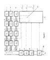
FIG. 2 is a schematic representation of one embodiment of a CO2 delivery device in accordance with the invention illustrating an optional scheme for organizing the flow of several added gases G1 to Gn (directly into the G0 stream) and relevant inputs into and outputs from a computer programmed to implement this embodiment of the invention.
FIG. 3 is a schematic representation useful for describing key volumetric control considerations underlying the presently disclosed scheme for adding one or more gases (Gn) containing a desired component gas DAn (e.g. CO2) to an inspiratory gas (G0) stream according to one embodiment of the invention.
FIG. 4 is a flow chart illustrating one embodiment of implementing a method according to the invention and related computer processing steps.
FIG. 5 is an illustration in a graph form of advantages of an embodiment of the invention for adding CO2 to an inspiratory gas stream.
The term “inspiratory gas” denoted G0 refers to any gas to which a gas consisting of or comprising a gas of interest (a component gas) is added. The G0 may be a principal gas provided to a subject for inhalation. For example, a ventilated patient may receive oxygen enriched gas as the G0. The G0 may also be one or more gases consisting or comprising desired component gases which may be individually or collectively considered a G0 with reference to another component gas. Accordingly the invention is concerned with but not limited to conditioning an inspiratory gas in the sense only of a principal gas and in one embodiment of the invention several added gases may be channeled into a manifold and each or the combination of several of them may be an inspiratory gas with reference to a particular component gas. Therefore, the invention contemplates that the necessary volumetric information is ascertained to track actual volumes of the component gas(es) of interest and the volume of gas e.g. the G0 or GR into which a component gas has been diluted.
The term “volume sensor” (which may also be referred to as a “volume sensing means”) means any device that can be used to directly or indirectly determine the volume of a gas that has passed through a breathing circuit or particular conduit thereof, typically with respect to a reference location in a breathing circuit. The invention contemplates that this can be accomplished by a variety of types of hardware including a flow meter, a gas concentration sensor (for example, a certain amount of any first gas of known composition can be inferred to have been delivered past a reference point if mixed with any second gas of known composition and volume by ascertaining the concentration of the first gas in a mixture of the first and second gases), a pressure transducer (for example, an added gas is sourced from a tank of fixed volume, and a pressure transducer in the tank could be used to determine the volume obtained from the tank).
As shown in FIGS. 1a, 1b and 1c , a system for adding CO2 to an inspiratory gas stream is exemplified by delivering controlled amounts of CO2 into a G0 channelling means exemplified in the form of an inspiratory limb 200 of a breathing circuit. A CO2 supply means, exemplified by tank 202 of pressurized CO2, is illustrated. The CO2 is carried by a conduit 204 made of inert tubing (does not react with CO2 and preferably other optional components of the gas Gn in the tank). Gas leaving the tank of pressurized CO2 is controlled by one or more flow regulators (206) for reducing the pressure of the gas coming out of the tank 202. For example, the pressure may be first be reduced by a single pressure regulator 206, or may be initially reduced to a range acceptable for a miniature pressure regulator, which in turn reduces the pressure of gas Gn further (e.g. CO2) to that required at the inlet of a gas delivery means 210, for example a means for delivering variable incremental volumes of CO2 e.g. a valve that opens proportionally to a control signal (referred to herein as a proportional flow control valve or proportional control valve). Alternatively, a two way solenoid 236 (illustrated in FIG. 1 for a different function) can be turned on an off intermittently to accomplish a form of gas delivery volume control. A pump or blower may serve the purpose in some instances. A computer, optionally in the form of microcontroller 212, optionally incorporates a controller (e.g. a PID controller) for controlling the output signal to the proportional control valve 210. The microcontroller 212 receives input and provides output via signal carrying means shown (with broken lines) as signal lines. Most importantly this input comprises: (1) the output of a sensor means or sensor 214 which serves to determining the actual volume (a “volume sensor”) of CO2 output by the proportional flow control valve 210. This volume sensor is optionally a flow meter 214 whose instantaneous or total output is integrated to get the incremental volume of inspired CO2, or the total accumulated volume of inspired CO2, respectively; (2) the output of a second “volume sensor” exemplified as an inspiratory flow meter 218 (output of the respiratory flow meter is integrated to get the accumulated volume of inspired inspiratory gas G0) for determining the actual volume of gas being delivered, for example at a selected junction in the inspiratory limb 200. The inspiratory limb 200 leads to a patient connection 220 which is or leads to a mask, endotracheal tube, etc. (not shown) generically referred to for convenience as a subject airway interface. Measurements made by the inspiratory flow meter made at discrete time points T1 . . . Tcurrent (each in succession, as time passes, a respective Tcurrent) enable the controlled delivery of incremental volumes of CO2 which are generally coordinately delivered with the inspiratory gas (G0) stream, in proportioned increments i.e. a calculated amount of CO2 which achieves the targeted fraction of CO2 in the blended volume of respiratory gas GR (FCO2T) by adjusting the cumulative volume of delivered CO2 to match the integrated flow of the inspiratory flow meter 218 so that the total volume of CO2 gas actually delivered matches FCO2T with respect to the total volume of the delivered respiratory gas of interest (delivered over an incrementally growing time period Tvariable). Optionally, a check valve 222 (e.g. Beswick CKVU) prevents back flow through the CO2 delivery line. One-way check valves 224, 226 (e.g. Hans Rudolph 5610) may be constituted by low resistance one-way valves that prevent the patient from expiring back in to the inspiratory limb 200, and from inhaling via expiratory limb 234. These one way valves (224, 226) also protect the respiratory flow meter 218 and minimize circuit dead space.
As shown in FIGS. 1a, 1b and 1c , for safety purposes a CO2 analyzer may be used to continuously monitor the inspired and expired fractional concentration of CO2. As described herein, a gas analyzer may also be indirectly used to a volume of gas passing by its location to the extent that a more diluted or concentrated gas may be used to determine what volumes of gas were mixed.
In one embodiment illustrated, for example in FIG. 1a , the microcontroller 212 reads a target % of CO2 (FCO2 T) and all the signals from the sensors and sends suitable control signals to the valve 210 and thereby implements suitable valve control (e.g. PID control). A monitor 230 displays information to the operator and a visible or audible signal generator 232 (e.g. a buzzer) may be used for safety to notify an operator if something goes wrong. In terms of safety features the microcontroller 212 may continuously receive input from the CO2 analyzer 228. If inspired and/or expired CO2 is high for a defined period of time then an optional two-way solenoid valve 236 may be closed, the proportional flow control valve 210 may be closed, and the buzzer 232 excited.
FIGS. 1a, 1b and 1c illustrate different configurations related to the placement of flow sensor 218. In a standard configuration, shown in FIG. 1a , when the inspiratory limb is connected to a ventilator (not shown) flow sensor may not accurately reflect the tidal volume of gas actually entering the patients lungs because the flow sensor 218 measures a compressible volume of gas that is compressed in and expands the tubing more proximal to the subject. Gas flowing through the flow sensor 218 may flow around the Y connection through to the expiratory limb 234. On the other hand, as illustrated in FIG. 1b , the placement of a flow sensor 218 at the mouth (proximal to the patient connection 220) adds dead space which may impair carbon dioxide elimination, especially in children and small adults. Furthermore, it adds bulk and weight to the patient airway interface. As illustrated in FIG. 1c , a cross-bridge 208, connecting the inspiratory 200 and expiratory 234 limbs, causes the flow sensor 218 to see only gas destined for inspiration by the patient as the compressible volume flows through the cross-bridge preventing passage through the flow sensor 218 or in a sense by-passing the flow sensor 218. Optionally, the G0 gas channeling means includes a flow-sensor by-pass means, such as described above, for obtaining an accurate measurement of G0 tidal volume actually flowing to the patient. This form of cross-bridge or by-pass means between inspiratory and expiratory sides can also be present in the ventilator such that a flow meter downstream thereof (towards the patient) in the tubing leading out to the connection to the inspiratory limb of a breathing circuit measures accurate tidal volumes flowing to the patient.
As shown in FIG. 2, according to one embodiment of an apparatus according to the invention several added gases G1 to Gn sourced from gas sources 410, 420 and 430, respectively, may optionally be directly added into the G0 stream. A volume sensor (VS0) 370 is operatively associated with the G0 delivery conduit 55 and is optionally located in the G0 conduit 55, optionally along with respective gas analyzers GS1,0 to GSn,0 (340, 350, 360) for each of the respective added gases which gases may be present in the inspiratory gas G0. Relevant inputs into and outputs from a computer 300 programmed to implement this embodiment of the invention include: inputs from optional gas analyzers GS1,0 to GSn,0 (340, 350, 360) and GS1 to GSn (380, 390, 400) (needed where the fractional concentration of gas of interest in an added gas is unknown or optionally for enhanced safety) and inputs from volume sensors 310, 320, 330, (as broadly defined herein) optionally located in the respective added gas delivery conduits 315, 325 and 335. Inputs of fractional concentrations of the respective component gases FDA1,R-FDAn,R enable a controller 345, optionally integrated as part of the computer 300, to direct outputs to respective gas delivery means GD1 to GDn (355, 365, 375) based on the actual incremental volumes of gas delivered by the gas delivery means as determined via the respective volume sensors VS0 (370) and VS1 to VSn (310, 320, 330). It will be appreciated that a component gas of interest does not need to be CO2 and may be any gas such O2, Xe, He, H2, NO, N2O, H2S, CO, SF6, an anesthetic, etc. In, for example, a compressed gas form, one or more such gases can be added to the G0 gas to compose a respiratory gas GR. The term DAn is generically used herein to refer to a component gas of interest and any reference herein to carbon dioxide, except where the context necessarily implies that carbon dioxide is being referred to specifically, may be replaced by a reference to DAn or any other specific component gas.
A device according to the invention may therefore comprise a wider or narrower variety of components that may be particularly useful or more readily substitutable for implementing a particular application of the invention. Furthermore, depending on a suitable range of deliverable volumes of gas in question, optionally attuned to a particular size range of a breath (e.g. for a premature human infant or small animal) the sizes and ranges of accuracy of components may be differently selected according to well understood design criteria.
In terms of optional embodiments, the GDn is optionally a proportional solenoid valve metering the release of Gn from a pressurized gas source. The invention also encompasses intermittently turning on and off a two-way solenoid valve metering the release of Gn from a pressurized gas source. Optionally, the GDn can be a gas pump, blower, or injector connected to a pressurized or unpressurized reservoir of Gn.
Input of CVGn actually delivered during T1 . . . Tnow is obtained via a volume sensor (VSn) operatively associated with a Gn delivery conduit. Input of CVG0 actually delivered during T1 . . . Tnow may be obtained via a second volume sensor (VS0) operatively associated with a G0 delivery conduit. A volume sensor can be constituted by any hardware for directly or indirectly measuring a volume of gas, for example, a spirometer, or a flow transducer or gas analyzer from which the flows of gases can be deduced (and then computing the integral of the flow).
The inputs, computations, and outputs described in the aforementioned method can be carried out by a variety of signal processing means including, but not limited to, a programmable processor, programmable microcontroller, dedicated integrated circuit, programmable integrated circuit, discrete analog or digital circuitry, mechanical components, optical components, or electrical components.
The VCn can be implemented by a variety of signal processing means including, but not limited to, a programmable processor, programmable microcontroller, dedicated integrated circuit, programmable integrated circuit, discrete analog or digital circuitry, mechanical components, optical components, or electrical components.
A Gn gas channeling means, optionally in the form of a Gn delivery conduit, is optionally adapted to be operatively associated with or directly fluidically connected to a G0 channeling means, for example, a G0 delivery conduit such as the inspiratory limb of a breathing circuit, a patient airway interface, a manifold for receiving multiple gas connections, or a connector interconnecting one or more of the above.
In one embodiment of the invention, all inputs, computations, and outputs are performed on a general purpose microcontroller. The Gn is a pressurized gas containing a known, fixed concentration of DAn. A rapid DAn analyzer is operatively associated with the G0 delivery conduit to ascertain the concentration of DAn in G0. A VSn is implemented by integrating the output of a flow transducer operatively associated with the Gn delivery conduit. A VS0 is implemented by integrating the output of a flow transducer operatively associated with the G0 delivery conduit. The VCn may be a PID controller implemented on a general purpose microcontroller. For each Tcurrent, GDn receives a weighted sum of the output of VCn and Gn P. The incremental G0 P predicted to be delivered in the time interval ΔT between the respective Tcurrent and a ensuing time point Tcurrent+ is equated with the incremental volume of G0 delivered in the time interval ΔT ending at Tcurrent. The GDn is implemented with a series of pressure regulators and a proportional solenoid valve metering the release of Gn from the pressurized source. The Gn delivery conduit is directly fluidically connected to the G0 channeling means so that the Gn is directly delivered into the G0 stream.
As shown in FIG. 3, implementation of the invention, preferably takes into account a cumulative volume of all of the several components of a respiratory gas G R 20 delivered to a subject including the respective volumes of one or more added gases V1, V2 . . . Vn which are coordinately delivered with an inspiratory gas (G0) stream, in proportioned increments i.e. a calculated amount of G n 10 which achieves the targeted fraction of DA n 30 in a volume of GR (DAn T) is consistently added to keep step with one or more recent incremental amounts of G0 and other added gases flowed to the subject. The term “coordinately” means involving coordination so as to update the fraction of DAn in a volume GR to a desirable extent in terms of frequency and accuracy. Optionally, keeping step with new incremental volumetric amounts of delivered G0 takes full advantage of the capabilities of the hardware of choice. For example, typical cost-effective hardware may be capable of delivering a proportioned amount of Gn (relative to an updated cumulative volume of G0 including the last confirmed incremental volume of G0 flowed to the subject) containing a known/determined fraction DAn to match DAn T—every millisecond. The curved arrow is used to imply controlled and confirmed (via some form of sensor) volumetric addition (e.g. via an appropriately controlled gas metering device e.g. a proportional solenoid under PID control) of a discrete corrective volume of a gas G n 10 containing a component gas of interest (DAn) to a confirmed total volume of delivered gas (including V1 . . . Vn, V0 and optionally DAn)—the confirmed cumulative GR volume (confirmed via cooperative action of a plurality of sensors of a broadly varying type and location of placement). It is understood that Gn may be made up entirely (100%) of DAn. As described herein, incremental amounts of DAn flowed to the subject are preferably at least “retrospectively corrective” to target DAn T, and as described below may optionally be a “predictively corrective” component (inasmuch as a predictive strategy can be termed “corrective” when serving the optional purpose of facilitating a retrospectively corrective strategy).
VDAn (represented by the oval area 40) is an accumulated volume of the component gas of interest that forms part of the volume of G R 20 delivered in virtue of being added at full concentration (Gn is 100% DAn) or blended (as illustrated) into one or more of V1, V2 . . . Vn. DAn may optionally also be a component of inspiratory gas G0. An error signal en according to a simple embodiment of the invention is the volume 10 of gas Gn that is needed to be delivered (based on what on has been “definitively” already delivered) to carry with it enough of the component gas of interest to ensure that the resulting amount of this component gas in a volume of the respiratory gas GR is incrementally maintained (subject to hardware time lags) and therefore consistently (to the extent practicable or desired) in the same proportion vis-à-vis the total volume of “definitively” delivered GR regardless of the changing total volume of gas that has been delivered to the subject. “Definitively” delivered amounts of Gn and GR are not amounts that the hardware would have delivered if responding perfectly to flow settings but volumes that requisite “sensors” determine have indeed flowed through the pertinent gas delivery conduits. The term “definitively” is used superfluously in the present description of FIG. 3 for extra emphasis to distinguish amounts theoretically flowed to the subject (the term “delivered” when used to refer to a volume of a gas implies a volume measured by some form of device—generically called a “volume sensor”—that directly or indirectly measures or enables volume computation—“delivered” is considered to sufficiently distinguish a “flow setting” or other “unverified delivery” modality used in prior devices). Variations on the above-described basic approach of “incrementally” correcting to a desired relative proportion—delivered DAn in delivered GR (retrospective) include adjunct “predictive correction” strategies for optimizing the error signal. Sub-optimal correction on the other hand may vary the size range of volumetric increments of G0 being corrected—the invention is best exploited by correcting small increments of newly delivered gas, optionally, but not necessarily, the smallest increments possible having regard to inherent limitations the hardware available or selected (e.g. cost effective) for use. In one embodiment, adjunct predictive correction involves predicting how much the volume of GR will grow from delivery of G0 in one or more ensuing increments of time (typically by predicting one or more ensuing incremental volumes of G0 based one or more recent G0 sensor readings) and computing an accommodative error signal even before the new gas is definitively delivered into the cumulative volume of GR. According to another embodiment, the computed en may take into account, only amounts of G0 and Gn definitively delivered. Variations on “computing” the error signal, involving a predictive correction factor are understood as adjunct strategies that are not inconsistent with baseline retrospective volumetric correction that broadly defines the invention in one aspect. Aside from “computing” a baseline error signal retrospectively, a controller, for example a PI or PID controller, would conventionally be used to appropriately implement the corrective en. Accordingly, compensating for hardware limitations inherent in delivering en may be seen to represent a distinct aspect of the totality of the volumetric corrective measure that would be expected to be implemented by an engineer in implementing the invention.
It may be appreciated that the strategy of the invention may be implemented to a useful extent if the incremental gas proportioning is consistent in the first part of inspiratory cycle (see FIG. 5) even if done in less than optimally small sequential as opposed to sporadic and/or wider spaced time increments. The first part of the inspiratory cycle of interest is the volume that destined to enter the alveoli as opposed to dead space volumes. Furthermore, in theory, the desired or chosen fraction of DAn in GR may be so small that computational inclusion of DAn as a necessary part of GR could be obviated for small cumulative volumes of DAn. Accordingly, the formulas and strategic approaches presented herein address embodiments of and options with respect to best and/or most universal practices and don't purport to cover all sub-optimal or circumventive strategies of exploiting the invention.
As shown in FIG. 4, one embodiment of a method (and related algorithm) according to the invention, may be expressed as a series of steps carried out with respect to each time increment Tcurrent (optionally a time increment that is optimized having regard to time delays of the computer, controllers, gas delivery means and sensors (volume, gas analyzer), wherein the computer:
    • 1. Reads inputs as exemplified in FIG. 4 (70)
    • 2. Calculates (90) the accumulated inspired volume of G0 (CVG0) by adding the volume of G0 inspired at the respective Tcurrent (to the accumulated volume of G0 determined as at the previous respective Tcurrent (CVG0-)) as measured by VS0
    • 3. Calculates (90) the accumulated inspired volume of each Gn (CVGn) by adding the volume of Gn inspired for the respective Tcurrent (to the accumulated volume of Gn determined as at the previous respective Tcurrent (CVGn-)) as measured by VSn
    • 4. For each DAn, determines (either from measurement or otherwise) FDAn,0 (80)
    • 5. For each DAn, determines (either from measurement or otherwise) FDAn,n (80)
    • 6. For each DAn, calculates (100) the accumulated inspired volume of pure DAn (CVGDAn) by adding the volume of G0 inspired the respective Tcurrent as measured by VS0 multiplied by FDAn,0 at Tcurrent, and adding the volume of Gn inspired during the time interval ending in Tcurrent as measured by VSn multiplied by FDAn during the respective Tcurrent (it will be appreciated that this type of computation may accomplished by calculating (90) the accumulated inspired volume of each Gn (CVGn) by adding the volume of Gn inspired during the respective Tcurrent especially where fractional concentration of DAn, in Gn is constant or is consistently 100%).
    • 7. For each DAn, calculates (110) an error signal (en) equal to the volume of Gn that must be added to the accumulated inspired volume of respiratory gas (CVGR) so that the volume of inspired DAn composes the target concentration of DAn (DAn T or FDAn,R) in CVGR (optionally the projected total inspired volume of respiratory gas at Tcurrent+)
CVG DAn + F DAn · e n CVG 0 + CVG n + e n = F DAn , R e n = F DAn , R ( CVG 0 + CVG n ) - CVG DAn F DAn - F DAn , R
    • 8. Delivers a signal to each GDn generated from the weighted sum of the current value of en, the derivative of en, and the integral of en (not shown).
The term DAn (and, as applicable, terms which reference DAn such as FDAn and CVGDAn) may for convenience be understood to be used expansively to reference embodiments of the invention in which there is one DAn as well as multiple DAns (more precisely DA1-n) since DAn in the latter scenario can be understood, if interpreted in a restrictive sense, to mean the last in the series 1 to n. In context, where more than one “DAn” is delivered as part of the cumulative volume of respiratory gas GR, with respect to each “DAn” (strictly speaking each respective DA1 . . . DAn), each other “DAn” can be understood to be taken into account as part of the G0 and hence the aforementioned generic formula for the error term en should be understood broadly to be generically applicable to each respective “DAn” (DA1 . . . n) based on the assumption that the volumes of the added gases other than the one for which the computation is being made are taken into account as part of the G0. The (+) sign with reference to a time point is used herein to refer to a future time point (not yet a Tcurrent) for which actual delivered (output by a Gn specific gas delivery device or ventilator) volumes of a component gas and G0/GR have not been ascertained. A minus (−) sign may be used to refer to a time point before a respective Tcurrent e.g. the most recent Tcurrent for which actual delivered (output) volumes have been ascertained.
It will be appreciated from the foregoing description that en may be a corrective volume to bring the concentration of DAn in line with DAn T as at Tcurrent without taking into account the incremental volume of G0 expected to be delivered by the next respective Tcurrent+1. Alternatively, the computation may take into account the expected incremental volume of G0 expected to be delivered by the next respective Tcurrent+ and hence the projected total of volume of respiratory gas expected to be delivered by the next Tcurrent including the en and its DAn content.
As shown in FIG. 5, panel A, a device according to the invention implements a form of closed loop volume control that enables the flow of G1 to maintain a target concentration of G1 in the total inspired volume, as early as possible in the breath. As shown in Panel B, this is especially important and advantageous with respect to the first part of a breath that fills the alveoli. As seen in Panel B, belated matching of the theoretical flow without later compensation accumulates volumetric error that will not achieve the targeted concentration of DAn in GR in the volume of GR destined to be part of volume of gas entering the alveoli. FIG. 5 is described in more detail below.
In one aspect, the volume of gas containing DAn is ideally delivered as part of the expanding volume of gas that is alveolar gas and not dead space gas. This is explained with reference to FIG. 5 described in more detail below.
The invention can therefore be understood to be broadly directed to a method for adding at least one added gas (Gn) to an inspiratory gas G0, to formulate a respiratory gas (GR) for delivery to a subject, and to maintain a targeted concentration of at least one component of an added gas G0 (DAn) in a volume of the GR comprising the steps of: for each of a series of time points of interest (generally time points in which G0 is being coordinately delivered with G0):
    • (a) obtaining input of confirmed incremental volumes of G0 or GR flowed to a subject;
    • (b) obtaining input of confirmed incremental volumes of G0 or pure DAn flowed to a subject;
    • c) computing for any respective Tcurrent an error signal (en) equal to the volume of Gn that must be coordinately delivered to the subject with the G0 so that the cumulative volume of DAn equals DAn T;
    • d) for any respective Tcurrent providing an output to GDn based on the en computed for the respective Tcurrent whereby the actual cumulative volume of DAn (generally coordinately delivered with CVG0 as part of CVGR) is controlled to target DAn T.
Thus in a broader aspect, the present invention relates to a device, method and system for delivering at least one added gas into an inspiratory gas stream to formulate a blended respiratory gas in a manner that continuously maintains a target concentration of the added gas in a volume of inspired respiratory gas, for example, over the course of a breath or a volumetrically definable part thereof or a series of partial or full breaths. The inspiratory gas may be a principal gas stream delivered to a patient such as air optionally having an enhanced oxygen content or air and oxygen combined with an anesthetic gas delivered by a ventilator or anesthetic machine but may also be comprised of several additive gases delivered individually or in blended form according to a method/device according to the invention.
A goal of most respiratory gas blenders is to deliver a target concentration of an additive gas into the inspired stream. Previously, this has been done by measuring the inspiratory flow and sending a signal to a flow controller to provide a flow of additive gas proportional to the inspired stream. Such a “flow-based control” system essentially tries to maintain the instantaneous concentration of the additive gas in the inspired gas at the target value. However, due to practical limitations of flow transducers and flow controllers, most notably finite response times, it is not possible for a flow controller to exactly “track” the inspired gas stream. Therefore, at any time during the breath, the instantaneous concentration of additive gas in the inspired stream may not be equal to the target concentration. Moreover, the overall concentration of additive gas in the accumulated inspired volume will not be equal to the target concentration. Furthermore, the design of previous respiratory gas blending systems overlooks that it is the concentration of additive gas, by volume, in the volume of inspired gas that reaches the alveoli that is the most important factor in many physiologic, therapeutic and/or diagnostic contexts.
The simplest gas blending systems try to match the flow of additive gas to the inspired stream with an open loop signal to a flow controller. That is, the actual flow of additive gas delivered by the flow controller is not monitored. If there is a systematic error/offset in the flow delivered by the flow controller, the flow of additive never reaches the target flow rate. Therefore, the instantaneous concentration of additive in the inspired stream never reaches target, and the concentration by volume in the accumulated inspired gas is always in error.
More complex blending systems try to match the flow of additive gas into the inspiratory gas stream with a closed loop signal to a flow controller. That is, the actual flow of additive gas delivered by the flow controller is monitored. If there is a systematic error/offset in the flow delivered by the flow controller, the signal to the flow controller is adjusted until the flow of additive reaches the desired flow rate. Therefore, the concentration of additive in the inspired stream may reach the target value as the breath proceeds, but because of an obligatory delay in response of the flow controller for the additive gas, the overall concentration by volume will always be less than the target concentration set at the beginning of the breath.
In one aspect, the present invention contemplates a control system in which the overall concentration of additive gas, in the volume inspired gas entering into the alveoli, reaches the desired value.
The invention contemplates that one or more additional gas delivery conduits may be operatively connected to or otherwise operatively associated with (via coordinated delivery into an airway interface) the G0 delivery conduit for coordinately delivering a controlled volume of an added gas Gn (or controlled volumes of a plurality of added gases G1 to Gn) with the G0 stream, wherein each G1-n is at least partially composed of a respective desired additive gas (DA1-n). In one embodiment, each gas delivery conduit carrying an added gas is operatively associated with a volume controller for controlling the volume of gas coordinately delivered with the G0, a volume sensor operatively associated with the added gas delivery conduit for continuously measuring the accumulated volume of the added gas. Optionally, where the fractional concentration of the added gas in G0 is not known, a means (for example a gas analyzer), operatively associated with the G0 delivery conduit, may be employed to measure, optionally continuously, the fraction of the added gas in the G0 delivery conduit. Optionally, for example for a given Gn, where the fractional concentration of the desired added gas in Gn (FDAn) is not known, a means, operatively associated with the Gn delivery conduit, for example a gas analyzer may be employed to measure, optionally continuously, FDAn in the Gn delivery conduit (GSn). For example, in one embodiment, for a gas Gn, the device may comprise:
    • (1) A volume controller (VCn) for controlling the volume of Gn added to G0
    • (2) A volume sensor (VSn) operatively associated with the Gn delivery conduit for continuously measuring the accumulated volume of inspired Gn
Optionally, where the fractional concentration of DAn in G0 (FDAn,0) is not known, a means, operatively associated with the G0 delivery conduit, to measure continuously FDAn,0 in the G0 delivery conduit (GSn,0)
    • (3) A computer that takes input of:
      • A target concentration of each DAn in the accumulated inspired volume (FDAn,1)
      • The output of VS0
      • The output of each VSn
      • Each FDAn,0 (either known or measured)
      • Each FDAn,n (either known or measured)
      • And provides output to each VCn.
On inspiration, gas entering the mouth or nose is conducted to the lung through a series of conduits consisting nasopharynx, oropharynx, trachea and bronchi. From the point of view of gas exchange, these are considered conducting vessels directing gas to the alveoli. As these conducting vessels do not contribute substantially to gas exchange, they are termed anatomical deadspace. In an average adult, they consist of about 2 ml per kg of body mass, or about 150 ml for the average adult. The alveoli are small saccules where the gas comes into close contact with blood and gas exchange takes place.
The distribution of gas during inspiration is well understood. At end expiration, the lung volume is smallest. In the course of inhalation gas is drawn through the anatomical deadspace into the alveoli. At end inspiration, the inspired gas is distributed between the alveoli and the anatomical deadspace. Note the last inhaled gas is retained in the anatomical deadspace. Physiologically the alveoli acts like a mixing chamber where the accumulated gases are mixed. The physiologic effect of an inhaled gas is determined by its net concentration once it has mixed in the alveolar space, that is, its fractional volume in the alveoli. Its instantaneous inhaled concentration is only important to the extent that it affects the net volume of that gas in the inspired volume. Although the flow-based controllers can reach an instantaneous target concentration of additive in the inspired stream, they are not directed towards providing a net concentration of a gas in the alveolar space where gas exchange takes place and where the net concentration of the added gas exerts its pharmacologic effect. This is illustrated in FIG. 5. The model is that of a subject being ventilated by a ventilator that provides a square wave inspiratory flow of G0 (this simplest of cases is used for illustrative purposes; the principle herein described applies to any inspiratory flow pattern by a ventilator or via spontaneous ventilation) and a target concentration of component gas 1 (G1). A required flow of G1 is required to attain this target concentration of G1 in the total inspired gas. At the beginning of inspiration the response delay in the flow controller results in a ramp up to target flow. The effect on the G1 concentration of the gas in the alveoli—the cumulative volumetric error resulting from the shortfall in the instantaneous concentration of additive G1 in the inspired stream during inhalation—is illustrated in the lower part of the figure. Note that the difference in the volume of G1 delivered to the alveoli, as represented by the difference between the between the curves “target flow G1” and that of the flow-based controllers, results in the volumetric concentration of G1 in the inspired gas reaching the alveoli always being less than the desired concentration. The instantaneous concentration of additive in the inspired stream is in greatest error at the start of the breath. Therefore, early terminations of the breath increase the discrepancy between desired concentration and actual concentration of G1 in the volume of inspired gas reaching the alveoli.
Previous devices have been designed on the premise that a response delay of a flow-based controller at the start of the breath is mirrored by an overshoot in G1 flow at the termination of the breath. Over the whole breath, this may result in an average alveolar G1 concentration at the desired level if the acceleration and deceleration profile of the breath are symmetrical. However with respect to ventilation, as illustrated in the lower part of FIG. 5, only the initial part of the breath reaches the alveoli. The overshoot in G1 flow at the termination of the breath in our model of a square wave inspiratory flow occurs during exhalation and provides no compensation to the lung concentration. With more sinusoidal inspiratory gas flow, there may be excess flow of G1 as the inspiratory flow of G0 slows down. However, at least part of the terminal aspect of the breath where the compensation takes place with flow-based control always resides in the anatomical deadspace and the increased compensatory flow of G1 does not reach the alveoli.
By contrast, a closed loop volume-based control provides early reconciliation of the G1 volume and the inspired volume of G0 such that the net inspired concentration of G1 is at the desired level very early in the breath. In practical terms, a volume controller according to the invention can provide fully compensated alveolar concentrations of G1 within as little as 10 ml of inspired volume and typically within 20-50 ml. Premature terminations of breaths after this level is reached would not affect the physiologically important net inspired concentration of G1 in the alveolar compartment of the lung.
Furthermore, with respect to the finite response time of any flow controller, the shorter the breath, and the greater the inspiratory flow, the more significant the delay period of the flow controller becomes with respect to providing the overall volumetric concentration of additive gas. Therefore for rapid breathing, where inspiratory flows are high and inspiratory times short, errors of DAn volumetric concentrations in the alveoli are magnified by response delays of flow controllers. Furthermore, even flow controllers with very rapid response times may still accumulate physiologically important errors of concentrations of DAn, particularly where DAn is a potent physiologic molecule (defined as having a large physiologic effect for a small change in concentration), in the overall volumetric concentration of DAn in the accumulated inspired volume.
The system according to the invention operates a closed control loop in order to maintain the concentration of additive, by volume, in the accumulated inspired volume at a target value throughout the breath. At each point in time, the total inspired volume and the total volume of inspired additive is assessed. An error signal is generated equal to the volume of additive that must be added to the inspiratory gas stream so that the overall concentration of additive, by volume, in the gas accumulated in the lung during inspiration will be equal to the target value throughout the breath. The error signal is provided to a volume controller which provides a signal to a gas delivery means (alternatively called a gas delivery device). This maintains the concentration of additive, by volume, in the accumulated inspired volume at the target value throughout the breath.
As described below, the invention contemplates that multiple gases can be combined according to a method of the invention or using a device, computer program product (including any known format in which the requisite program code can be recorded or hard-wired), processor or system according to the invention based on adaptations described herein and evident to those skilled in the art. A reference to blending or delivering a Gn in tandem with a G0 that does not explicitly specify a single Gn and that can be understood to be a general case in which there is more than one added gas having the same or a different component gas of interest are meant to disclose this general case of the invention in which permutations and adaptations to accommodate more than one added component are understood to be related. Furthermore each of the general classes and specific embodiments of the invention are meant to refer back to the variety of aspects of the invention described herein and any logistical permutation of these various classes of and specific embodiments are understood to be described within the general concepts for implementing the invention elaborated above. Therefore, while a number of exemplary aspects and embodiments have been discussed above, those of skill in the art will recognize certain modifications, permutations, additions and sub-combinations thereof. It is therefore intended that the foregoing description and following appended claims and claims hereafter introduced are interpreted to include all such modifications, permutations, additions and sub-combinations as are within their true spirit and scope. Alternative terms for any features, elements, components etc of the invention as defined herein are not meant to be differentiated by virtue of the use of alternative language and each term is intended to be given its broadest meaning consistent with the context and the function it serves according the description of the invention as a whole. The scope of the claims should not be limited by the preferred embodiments, but should be given the broadest interpretation consistent with the description of the invention as a whole.
REFERENCE LIST
  • 1. Prisman E, Slessarev M, Azami T, Nayot D, Milosevic M, Fisher J. Modified oxygen mask to induce target levels of hyperoxia and hypercarbia during radiotherapy: a more effective alternative to carbogen. Int J Radiat Biol 2007; 83(7):457-462.
  • 2. Hoskin P J, Abdelath O, Phillips H et al. Inspired and expired gas concentrations in man during carbogen breathing. Radiother Oncol 1999; 51(2):175-177.
  • 3. Mark C I, Slessarev M, Ito S, Han J, Fisher J A, Pike G B. Precise control of end-tidal carbon dioxide and oxygen improves BOLD and ASL cerebrovascular reactivity measures. Magn Reson Med 2010.
  • 4. Mark C I, Fisher J A, Pike G B. Improved fMRI calibration: Precisely controlled hyperoxic versus hypercapnic stimuli. Neuroimage 2011; 54(2):1102-1111.
  • 5. Slessarev M, Han J, Mardimae A et al. Prospective targeting and control of end-tidal CO2 and O2 concentrations. J Physiol 2007; 581(Pt 3):1207-1219.
  • 6. Ito S, Mardimae A, Han J et al. Non-invasive prospective targeting of arterial P(CO2) in subjects at rest. J Physiol 2008; 586(Pt 15):3675-3682.

Claims (25)

I claim:
1. An apparatus for adding at least one added gas (Gn) to an inspiratory gas (G0) to formulate a respiratory gas (GR) for delivery to a subject, comprising:
a control system operable to maintain a targeted concentration (DAn T) of at least one component (DAn) of the at least one added gas (Gn) in a respective cumulative volume of the respiratory gas (CVGR) delivered over a respective cumulative time period consisting of a cumulating series of respective time points of interest, the control system including a processor operable to:
(a) obtain input of confirmed incremental volumes of at least one of the inspiratory gas (G0) and the respiratory gas (GR) flowed to the subject with respect to the respective time points of interest; and
(b) obtain input of confirmed incremental volumes of at least one of the at least one added gas (Gn) and the at least one component (DAn) of the at least one added gas flowed to the subject with respect to the respective time points of interest; and
(c) compute for successive respective time intervals between contiguous respective time points of interest, a respective error signal (en) representing an incremental volume of the at least one added gas (Gn) that would, if delivered with respect to the respective time interval, maintain the target concentration (DAn T) of the at least one component (DAn) of the at least one added gas in a cumulative volume of the respiratory gas (GR) including the incremental volume of the at least one added gas;
the control system being operable to provide an output signal to a gas delivery device (GDn) for the respective time interval based on the respective error signal (en) computed for the respective time interval such that the target concentration (DAn T) of the at least one component (DAn) of the at least one added gas (Gn) is maintained in a respective cumulative volume of the respiratory gas (GR).
2. An apparatus according to claim 1, wherein the control system is operable to obtain input of confirmed incremental volumes of at least one of the inspiratory gas (G0) and the respiratory gas (GR) flowed to the subject with respect to the respective time points of interest, and confirmed incremental volumes of the at least one added gas (Gn) flowed to the subject with respect to the respective time points of interest; the control system being configured to compute respective cumulative volumes of delivered respiratory gas (GR) over respective cumulative time intervals comprising the respective time points of interest and respective cumulative volumes of delivered added gas (Gn) with respect to the respective cumulative time intervals and the respective error signal (en) for the successive respective time intervals between the contiguous respective time points of interest.
3. An apparatus according to claim 2, wherein the output to the gas delivery device (GDn) for each successive respective time interval is generated from a weighted sum of the respective error signal (en) computed for the respective time point of interest and the integral of the respective error signal (en) computed for the respective time point of interest.
4. An apparatus according to claim 2, wherein the gas delivery device (GDn) is controlled by a controller selected from the group consisting of a PI controller and a PID controller.
5. An apparatus according to claim 4, wherein the output signal delivered to the gas delivery device (GDn) is computed based on:
a) an output of the controller; and
b) an incremental volume (G0 P) of inspiratory gas (G0) expected to be delivered in a time interval ΔT between the respective time point of interest and an ensuing respective time point of interest.
6. An apparatus according to claim 1, wherein the processor is operable to obtain input from a volume sensor and provide output to a proportional control valve.
7. An apparatus according to claim 1, further comprising:
at least one added gas delivery conduit, wherein the gas delivery device (GDn) is operable for delivering incremental volumes of the at least one added gas (Gn) into the at least one added gas delivery conduit; and
a volume sensor positioned to provide output of respective incremental volumes of the at least one added gas (Gn) delivered by the gas delivery device (GDn) into the at least one added gas delivery conduit.
8. An apparatus according to claim 1, wherein the processor, is embodied in a device selected from the group consisting of, a microcontroller and an IC chip.
9. An apparatus according to claim 1, wherein the processor is configured to obtain input of a concentration of the at least one component (DAn) of the at least one added gas (Gn) in the at least one added gas (Gn) applicable to any respective time point of, interest from a gas analyzer.
10. An apparatus according to claim 1, wherein the at least one component of the at least one added gas (DAn) is carbon dioxide.
11. A method for adding at least one added gas (Gn) to an inspiratory gas (G0) to formulate a respiratory gas (GR) for delivery to a subject, comprising:
maintaining a targeted concentration (DAn T) of at least one component (DAn) of the at least one added gas (Gn)—in a respective cumulative volume (CVGR) of the respiratory gas delivered over a respective cumulative time period consisting of a cumulating series of respective time points of interest, by:
(a) obtaining input of confirmed incremental volumes of at least one of the inspiratory gas (G0) and the respiratory gas (GR) flowed to the subject at the respective time points of interest;
(b) obtaining input of confirmed incremental volumes of at least one of the at least one added gas (Gn) and the at least one component (DAn) of the at least one added gas flowed to the subject at the respective time points of interest; and
(c) computing for successive respective time intervals between contiguous respective time points of interest, a respective error signal (en) representing an incremental volume of the at least one added gas (Gn) that would, if delivered with respect to the respective time interval, maintain the target concentration (DAn T) of the at least one component (DAn) of the at least one added gas in a cumulative volume of respiratory gas (CVGR) including the incremental volume of the at least one added gas;
(d) providing, via a controller, an output signal to a gas delivery device (GDn) for the respective time interval based on the respective error signal (en) computed for the respective time interval, —such that the target concentration of the at least one component gas (DAn T) is maintained in a respective cumulative volume of the respiratory gas (GR).
12. A method according to claim 11, comprising controlling the gas delivery device (GDn) using a controller selected from the group consisting of a PI and a PID controller.
13. A method according to claim 11, wherein a processor obtains input values for each of the respective time points of interest, the input values including confirmed incremental volumes of the least one added gas (Gn) and at least one of confirmed incremental volumes of the inspiratory gas (G0) and confirmed incremental volumes of the respiratory gas (GR), the input values being sufficient to compute, for the respective cumulative time period, the respective cumulative time period including previous respective time points of interest and the last respective time point of interest:
i) cumulative volumes of the at least one added gas (Gn) and at least one of cumulative volumes of the inspiratory gas (G0) and cumulative volumes of the respiratory gas (GR); and
ii) the respective error signal (en) with respect to a respective time interval based on the cumulative volumes computed in step i);
the respective error signal (en) corresponding to a respective time interval computed by the processor using the cumulative volumes of the at least one added gas (Gn) cumulatively delivered over the respective cumulative time period and at least one of the cumulative volumes of the inspiratory gas (G0) and cumulative volumes of the respiratory gas (GR) cumulatively delivered over the respective cumulative time period.
14. A method according to claim 11, wherein the output signal delivered to the gas delivery device (GDn) is computed based on:
a) an output of the controller; and
b) an incremental volume of inspiratory gas (G0 P) expected to be delivered in a time interval ΔT between one respective time point of interest and an ensuing respective time point of interest.
15. A method according to claim 14, wherein the signal delivered to the gas delivery device (GDn) is computed based on the sum of the output of the controller and a volume (Gn P) of the at least one added gas (Gn) that must be added to the incremental volume of the inspiratory gas (G0 P), so that the incremental volume of the at least one component of the at least one added gas (DAn) in the combined volume of G0 P and Gn P equals the target concentration (DAn T).
16. A method according to claim 15, wherein the incremental volume of the inspiratory gas (G0 P) is equated with one of (i) the incremental volume of the inspiratory gas delivered in the time interval ΔT beginning at an immediately previous respective time point of interest, and ending at the respective time point of interest, and (ii) an average or weighted average of the incremental volumes of the inspiratory gas delivered in, a plurality of time intervals of interest within the respective cumulative time period.
17. A method according to claim 11, wherein the method is implemented by using a processor operatively associated with a volume controller (VCn) for controlling a gas delivery device (GDn), the processor operable to obtain input from a plurality of sensors selected from the group consisting of volume sensors and gas analyzers.
18. A method according to claim 11, wherein the at least one component of the at least one added gas (DAn) is carbon dioxide.
19. A computer readable medium encoded with computer-readable instructions that, when executed by a programmable computer, are operable for controlling a gas delivery device controlled by the computer to add at least one added gas (Gn) to an inspiratory gas (G0) to formulate a respiratory gas (GR) for delivery to a subject, characterized in that the instructions, when executed by the computer, are operable for maintaining a targeted concentration (DAn T) of at least one component of the at least one added gas (DAn) in a respective cumulative volume of the respiratory gas (CVGR) delivered over a respective cumulative time period consisting of a cumulating series of respective time points of interest, by:
(a) inputting to the computer data representing confirmed incremental volumes of at least one of the inspiratory gas (G0) and the respiratory gas (GR) flowed to the subject at the respective time points of interest;
(b) inputting to the computer confirmed incremental volumes of at least one of the at least one added gas (Gn) and the at least one component (DAn) of the at least one added gas flowed to the subject at the respective time points of interest; and
(c) operating the computer to generate, for successive respective time intervals between contiguous respective time points of interest, a respective error signal (en) representing a incremental volume of the at least one added gas (Gn) that would, if delivered with respect to a respective time interval maintain the target concentration (DAn T) of the at least one component (DAn) of the at least one added gas in a cumulative volume of the respiratory gas including the incremental volume of the at least one added gas; and
(d) providing an output signal from the computer to a gas delivery device (GDn) for the respective time interval based on the respective error signal (en) computed for the respective time interval, such that the target concentration (DAn T) of the at least one component (DAn) of the at least one added gas (Gn) is maintained in respective cumulative volume of the respiratory gas (GR).
20. A computer readable medium according to claim 19, wherein the instructions are operable, when executed by the computer, to control the gas delivery device by a controller selected from the group consisting of a PI controller and a PID controller.
21. A computer readable medium according to claim 19, wherein the instructions are operable, when executed by the computer, to obtain input values from a volume sensor for each of the respective time points of interest, the input values including confirmed incremental volumes of at least one added gas (Gn) and at least one of confirmed incremental volumes of the inspiratory gas (G0) and confirmed, incremental volumes of the respiratory gas (GR), the input values sufficient to compute, for the respective cumulative time period, the respective cumulative time period including previous respective time points of interest and the last respective time point of interest;
i) cumulative volumes of the at least one added gas (Gn) and at least one of cumulative volumes of the inspiratory gas (G0) and emulative volumes of the respiratory gas (GR); and
ii) the respective error signal (en) with respect to a respective time interval based on the cumulative volumes computed in step i);
the error signal (en) corresponding to a respective time interval computed using the cumulative volumes of the at least one added gas Gn cumulatively delivered over the respective cumulative time period and at least one of the cumulative volumes of the inspiratory gas (G0) and cumulative volumes of the respiratory gas (GR) cumulatively delivered over the respective cumulative time period.
22. A computer readable medium according to claim 19, wherein the signal delivered to the gas delivery device (GDn) is provided by a controller and computed based on:
a) the respective error signal (en) output by the controller; and
b) an incremental volume of inspiratory gas (G0 P) expected to be delivered in a time interval ΔT between the respective time point of interest and an ensuing respective time point of interest.
23. A computer readable medium, according to claim 22, wherein the signal delivered to the gas delivery device (GDn) is computed based on the sum of the output of the controller and a volume of the at least one added gas (Gn P) that must be added to the incremental volume of inspiratory gas (G0 P), so that the incremental volume of the at least one component of the at least one added gas (DAn) in the combined volume of G0 P and Gn P equals the target concentration (DAn T).
24. A computer readable medium according to claim 23, wherein the incremental volume of inspiratory gas (G0 P) is equated with one of (i) the incremental volume of inspiratory gas G0 delivered in the time interval ΔT beginning at an immediately previous respective time point of interest and ending at the respective time point of interest, and (ii) an average or weighted average of the incremental volumes of inspiratory gas (G0) delivered in a plurality of time intervals of interest within the respective cumulative time period.
25. A computer readable medium according to claim 19, wherein the computer is operatively associated with a volume controller (VCn) for controlling the gas delivery device (GDn) in accordance with input to the computer from a plurality of sensors selected from the group consisting of volume sensors and gas analyzers.
US14/111,993 2011-04-13 2012-04-12 Gas delivery method and apparatus Active 2033-06-09 US9555209B2 (en)

Priority Applications (1)

Application Number Priority Date Filing Date Title
US14/111,993 US9555209B2 (en) 2011-04-13 2012-04-12 Gas delivery method and apparatus

Applications Claiming Priority (3)

Application Number Priority Date Filing Date Title
US201161475106P 2011-04-13 2011-04-13
PCT/CA2012/000351 WO2012139204A1 (en) 2011-04-13 2012-04-12 Gas delivery method and apparatus
US14/111,993 US9555209B2 (en) 2011-04-13 2012-04-12 Gas delivery method and apparatus

Related Parent Applications (1)

Application Number Title Priority Date Filing Date
PCT/CA2012/000351 A-371-Of-International WO2012139204A1 (en) 2011-04-13 2012-04-12 Gas delivery method and apparatus

Related Child Applications (1)

Application Number Title Priority Date Filing Date
US15/405,069 Continuation US10576238B2 (en) 2011-04-13 2017-01-12 Gas delivery method and apparatus

Publications (2)

Publication Number Publication Date
US20140053837A1 US20140053837A1 (en) 2014-02-27
US9555209B2 true US9555209B2 (en) 2017-01-31

Family

ID=47008738

Family Applications (3)

Application Number Title Priority Date Filing Date
US14/111,993 Active 2033-06-09 US9555209B2 (en) 2011-04-13 2012-04-12 Gas delivery method and apparatus
US15/405,069 Active 2033-05-29 US10576238B2 (en) 2011-04-13 2017-01-12 Gas delivery method and apparatus
US16/781,665 Active 2033-06-10 US11464934B2 (en) 2011-04-13 2020-02-04 Gas delivery method and apparatus

Family Applications After (2)

Application Number Title Priority Date Filing Date
US15/405,069 Active 2033-05-29 US10576238B2 (en) 2011-04-13 2017-01-12 Gas delivery method and apparatus
US16/781,665 Active 2033-06-10 US11464934B2 (en) 2011-04-13 2020-02-04 Gas delivery method and apparatus

Country Status (6)

Country Link
US (3) US9555209B2 (en)
EP (2) EP2696927B1 (en)
JP (1) JP2014514073A (en)
CN (1) CN103826685A (en)
CA (1) CA2833018A1 (en)
WO (1) WO2012139204A1 (en)

Cited By (2)

* Cited by examiner, † Cited by third party
Publication number Priority date Publication date Assignee Title
US20170246418A1 (en) * 2011-04-13 2017-08-31 Michael Klein Gas delivery method and apparatus
US11013874B2 (en) 2015-12-29 2021-05-25 Vapotherm, Inc. Methods and systems for obtaining desired oxygen concentrations and air flows during respiratory therapy

Families Citing this family (20)

* Cited by examiner, † Cited by third party
Publication number Priority date Publication date Assignee Title
US9150793B2 (en) 2008-11-03 2015-10-06 Nalco Company Method of reducing corrosion and corrosion byproduct deposition in a crude unit
US9458388B2 (en) 2008-11-03 2016-10-04 Nalco Company Development and implementation of analyzer based on control system and algorithm
WO2012151583A1 (en) * 2011-05-05 2012-11-08 Cedars-Sinai Medical Center Assessment of coronary heart disease with carbon dioxide
US11129911B2 (en) * 2011-05-05 2021-09-28 Cedars-Sinai Medical Center Assessment of coronary heart disease with carbon dioxide
US20140170069A1 (en) * 2011-05-05 2014-06-19 Cedars-Sinai Medical Center Assessment of coronary heart disease with carbon dioxide
CA2861506A1 (en) 2011-12-05 2013-06-13 Michael Klein An apparatus to attain and maintain target end tidal partial pressure of a gas
IN2014MN02064A (en) 2012-03-19 2015-08-21 Michael Klein
JP2015521059A (en) 2012-04-30 2015-07-27 マイケル, クラインMichaelKLEIN Novel method and apparatus for reaching and maintaining target arterial blood gas concentrations using a ramp sequence
TWI580771B (en) 2012-07-25 2017-05-01 奈寇公司 Design development and implementation of analyzer based control system and algorithm
JP5667224B2 (en) * 2013-02-06 2015-02-12 日本特殊陶業株式会社 Oxygen concentrator
US10449311B2 (en) 2013-06-05 2019-10-22 Thornhill Scientific Inc. Controlling arterial blood gas concentration
EP3003446A4 (en) * 2013-06-05 2017-01-11 Michael Klein Controlling arterial blood gas concentration
US10471094B2 (en) 2013-08-05 2019-11-12 Cedars-Sinai Medical Center Methods for reducing ischemia-reperfusion injury via targeted control of blood gases
EP3086831B1 (en) * 2013-12-27 2020-09-23 St. Michael's Hospital System for providing ventilatory assist to a patient
EP3139986B1 (en) * 2014-05-09 2019-05-01 Ino Therapeutics LLC System for delivery of therapeutic gas
CN108135489B (en) * 2015-10-09 2021-11-02 皇家飞利浦有限公司 Enhanced acute care management combining imaging with physiological monitoring
US20170181664A1 (en) * 2015-12-29 2017-06-29 Ethicon Endo-Surgery, Inc. Sedation system with multi-input capnometer
CN110740691B (en) * 2017-04-10 2023-04-11 美国专利创新有限公司 Electrosurgical gas control module
CN111324154B (en) * 2020-01-20 2022-06-24 深圳市科曼医疗设备有限公司 Mixed cavity pressure control method, ventilator device and computer readable storage medium
KR102516898B1 (en) * 2020-04-24 2023-04-03 고려대학교 산학협력단 Smart ventilator splitter using end-tidal CO2

Citations (31)

* Cited by examiner, † Cited by third party
Publication number Priority date Publication date Assignee Title
US5094235A (en) * 1989-05-10 1992-03-10 Dragerwerk Aktiengesellschaft Anesthesia ventilating apparatus having a breathing circuit and control loops for anesthetic gas components
US5320093A (en) * 1990-12-21 1994-06-14 Brigham And Women's Hospital Rapid anesthesia emergence system using closed-loop PCO2 control
US5540233A (en) * 1993-10-22 1996-07-30 Siemens-Elema Ab Method for determining the functional residual capacity of lungs and a ventilator for practicing said method
US5558083A (en) * 1993-11-22 1996-09-24 Ohmeda Inc. Nitric oxide delivery system
US5918596A (en) * 1997-04-22 1999-07-06 Instrumentarium Corp. Special gas dose delivery apparatus for respiration equipment
US5957129A (en) * 1997-07-30 1999-09-28 Ohmeda Inc. On-line fault detection and correction in anesthesia delivery system
US6139506A (en) * 1999-01-29 2000-10-31 Instrumentarium Oy Method for measuring pulmonary functional residual capacity
US6216690B1 (en) * 1997-10-15 2001-04-17 Datex-Ohmeda, Inc. Method and apparatus for rapid control of set inspired gas concentration in anesthesia delivery systems
EP1238631A1 (en) 2001-03-05 2002-09-11 Instrumentarium Corporation A method for non-invasively determining conditions in the circulatory system of a subject
US20020185126A1 (en) * 1997-01-17 2002-12-12 Christian Krebs Controlled gas-supply system
US20020185129A1 (en) * 2001-05-04 2002-12-12 Joseph Fisher Method of maintaining constant arterial PCO2 and measurement of anatomic and alveolar dead space
US20040144383A1 (en) * 2003-01-28 2004-07-29 Beth Israel Deaconess Medical Center, Inc. Gas systems and methods for enabling respiratory stability
US6983750B2 (en) * 2003-08-26 2006-01-10 Instrumentarium Corp. Method for indicating the amount of ventilation inhomogeneity in the lung
US7150717B2 (en) * 2003-02-17 2006-12-19 Hitachi, Ltd. Optical measurement apparatus for a living body
DE102005053358A1 (en) 2005-11-07 2007-05-10 Lenk, Norbert, Dr. Device for controlled supply of ozone, preferably in cosmetic and/or therapeutic purposes, comprises an ozone generator, a water tank, an ozone sensor and an inhalation unit
US20070181126A1 (en) * 2006-02-08 2007-08-09 Tolmie Craig R Method and apparatus for ventilating a patient with a breathing gas mixture formed from nitric oxide, air, and oxygen
US20070221224A1 (en) * 2006-03-20 2007-09-27 Ric Investments, Llc Ventilatory control system
EP1923088A2 (en) 2003-01-28 2008-05-21 Beth Israel Deaconess Medical Center, Inc. Gas systems and methods for enabling respiratory stability
US7516742B2 (en) * 1999-11-24 2009-04-14 Cardinal Health 207, Inc. Method and apparatus for delivery of inhaled nitric oxide to spontaneous-breathing and mechanically-ventilated patients with intermittent dosing
US20090120435A1 (en) 2005-07-28 2009-05-14 Marat Slessarev method and apparatus to attain and maintain target end tidal gas concentrations
US20090241960A1 (en) 2008-04-01 2009-10-01 Event Medical, Inc. Dual high and low pressure breathing system
US7621272B2 (en) * 2003-05-01 2009-11-24 Anecare Laboratories, Inc. Apparatus and techniques for reducing the effects of general anesthetics
US20100224191A1 (en) * 2009-03-06 2010-09-09 Cardinal Health 207, Inc. Automated Oxygen Delivery System
CN101829386A (en) 2010-05-25 2010-09-15 张培林 Intelligent fresh gas flow and oxygen concentration control device for anesthesia machine
US7959443B1 (en) * 2005-09-12 2011-06-14 IngMar Medical, Ltd. Lung simulator
US20120215124A1 (en) * 2011-02-04 2012-08-23 Joseph Fisher Non-invasive arterial blood gas determination
US20120272957A1 (en) * 2011-01-10 2012-11-01 General Electric Company System and Method of Controlling the Delivery of Medical Gases to a Patient
US20140158124A1 (en) * 2011-01-13 2014-06-12 Université De Bretagne Occidentale Method and system for the delivery of carbon dioxide to a patient
US8789524B2 (en) * 2008-01-22 2014-07-29 General Electric Company Pulse width modulated medical gas concentration control
US20150034085A1 (en) * 2012-03-19 2015-02-05 Michael Klein Virtual respiratory gas delivery systems and circuits
US20160128609A1 (en) * 2009-10-15 2016-05-12 Ipr Holding Aps Combination of inert gas rebreathing and multiple-breath wash-out techniques for determination of indices of ventilation inhomogeneity

Family Cites Families (7)

* Cited by examiner, † Cited by third party
Publication number Priority date Publication date Assignee Title
JPH01321508A (en) * 1988-06-23 1989-12-27 Kojima Seisakusho:Kk Oxygen density controller
US6076523A (en) * 1998-01-15 2000-06-20 Nellcor Puritan Bennett Oxygen blending in a piston ventilator
DE102005060171A1 (en) 2005-12-14 2007-06-21 Uhde Gmbh Oxidation reactor and oxidation process
EP2259823A1 (en) * 2008-03-31 2010-12-15 Nellcor Puritan Bennett LLC Ventilator based on a fluid equivalent of the "digital to analog voltage" concept
RU2538240C2 (en) 2009-03-23 2015-01-10 Конинклейке Филипс Электроникс Н.В. Device and method for gas mixing control
CN201399147Y (en) * 2009-03-23 2010-02-10 王中 Respirator air-oxygen mixing device with compressed air
JP2014514073A (en) * 2011-04-13 2014-06-19 マイケル,クライン Gas delivery method and apparatus

Patent Citations (32)

* Cited by examiner, † Cited by third party
Publication number Priority date Publication date Assignee Title
US5094235A (en) * 1989-05-10 1992-03-10 Dragerwerk Aktiengesellschaft Anesthesia ventilating apparatus having a breathing circuit and control loops for anesthetic gas components
US5320093A (en) * 1990-12-21 1994-06-14 Brigham And Women's Hospital Rapid anesthesia emergence system using closed-loop PCO2 control
US5540233A (en) * 1993-10-22 1996-07-30 Siemens-Elema Ab Method for determining the functional residual capacity of lungs and a ventilator for practicing said method
US5558083A (en) * 1993-11-22 1996-09-24 Ohmeda Inc. Nitric oxide delivery system
US20020185126A1 (en) * 1997-01-17 2002-12-12 Christian Krebs Controlled gas-supply system
US5918596A (en) * 1997-04-22 1999-07-06 Instrumentarium Corp. Special gas dose delivery apparatus for respiration equipment
US5957129A (en) * 1997-07-30 1999-09-28 Ohmeda Inc. On-line fault detection and correction in anesthesia delivery system
US6216690B1 (en) * 1997-10-15 2001-04-17 Datex-Ohmeda, Inc. Method and apparatus for rapid control of set inspired gas concentration in anesthesia delivery systems
US6139506A (en) * 1999-01-29 2000-10-31 Instrumentarium Oy Method for measuring pulmonary functional residual capacity
US7516742B2 (en) * 1999-11-24 2009-04-14 Cardinal Health 207, Inc. Method and apparatus for delivery of inhaled nitric oxide to spontaneous-breathing and mechanically-ventilated patients with intermittent dosing
EP1238631A1 (en) 2001-03-05 2002-09-11 Instrumentarium Corporation A method for non-invasively determining conditions in the circulatory system of a subject
US20020185129A1 (en) * 2001-05-04 2002-12-12 Joseph Fisher Method of maintaining constant arterial PCO2 and measurement of anatomic and alveolar dead space
US20040144383A1 (en) * 2003-01-28 2004-07-29 Beth Israel Deaconess Medical Center, Inc. Gas systems and methods for enabling respiratory stability
EP1923088A2 (en) 2003-01-28 2008-05-21 Beth Israel Deaconess Medical Center, Inc. Gas systems and methods for enabling respiratory stability
US7150717B2 (en) * 2003-02-17 2006-12-19 Hitachi, Ltd. Optical measurement apparatus for a living body
US7621272B2 (en) * 2003-05-01 2009-11-24 Anecare Laboratories, Inc. Apparatus and techniques for reducing the effects of general anesthetics
US6983750B2 (en) * 2003-08-26 2006-01-10 Instrumentarium Corp. Method for indicating the amount of ventilation inhomogeneity in the lung
US8459258B2 (en) * 2005-07-28 2013-06-11 Thornhill Scientific Inc. Method and apparatus to attain and maintain target end tidal gas concentrations
US20090120435A1 (en) 2005-07-28 2009-05-14 Marat Slessarev method and apparatus to attain and maintain target end tidal gas concentrations
US7959443B1 (en) * 2005-09-12 2011-06-14 IngMar Medical, Ltd. Lung simulator
DE102005053358A1 (en) 2005-11-07 2007-05-10 Lenk, Norbert, Dr. Device for controlled supply of ozone, preferably in cosmetic and/or therapeutic purposes, comprises an ozone generator, a water tank, an ozone sensor and an inhalation unit
US20070181126A1 (en) * 2006-02-08 2007-08-09 Tolmie Craig R Method and apparatus for ventilating a patient with a breathing gas mixture formed from nitric oxide, air, and oxygen
US20070221224A1 (en) * 2006-03-20 2007-09-27 Ric Investments, Llc Ventilatory control system
US8789524B2 (en) * 2008-01-22 2014-07-29 General Electric Company Pulse width modulated medical gas concentration control
US20090241960A1 (en) 2008-04-01 2009-10-01 Event Medical, Inc. Dual high and low pressure breathing system
US20100224191A1 (en) * 2009-03-06 2010-09-09 Cardinal Health 207, Inc. Automated Oxygen Delivery System
US20160128609A1 (en) * 2009-10-15 2016-05-12 Ipr Holding Aps Combination of inert gas rebreathing and multiple-breath wash-out techniques for determination of indices of ventilation inhomogeneity
CN101829386A (en) 2010-05-25 2010-09-15 张培林 Intelligent fresh gas flow and oxygen concentration control device for anesthesia machine
US20120272957A1 (en) * 2011-01-10 2012-11-01 General Electric Company System and Method of Controlling the Delivery of Medical Gases to a Patient
US20140158124A1 (en) * 2011-01-13 2014-06-12 Université De Bretagne Occidentale Method and system for the delivery of carbon dioxide to a patient
US20120215124A1 (en) * 2011-02-04 2012-08-23 Joseph Fisher Non-invasive arterial blood gas determination
US20150034085A1 (en) * 2012-03-19 2015-02-05 Michael Klein Virtual respiratory gas delivery systems and circuits

Non-Patent Citations (8)

* Cited by examiner, † Cited by third party
Title
Hoskin et al.; "Inspired and expired gas concentrations in man during carbogen breathing"; Radiotherapy and Oncology 51; Jan. 5, 1999; pp. 175-177.
International Search Report on related PCT application (PCT/CA2012/000351); International Searching Authority (CA) dated Aug. 1, 2012.
Ito et al.; "Non-invasive prospective targeting of arterial PCO2 in subjects at rest"; J Physiol 586.15; Jun. 19, 2008; pp. 3675-3682.
Mark et al.; "Improved fMRI calibration: Precisely controlled hyperoxic versus hypercapnic stimuli"; NeuroImage 54; Sep. 7, 2010; pp. 1102-1111.
Mark et al.; "Precise control of end-tidal carbon dioxide and oxygen improves BOLD and ASL cerebrovascular reactivity measures"; Magnetic Resonance in Medicine 64; Jul. 20, 2010; pp. 749-756.
Prisman et al.; "Modified oxygen mask to induce target levels of hyperoxia and hypercarbia during radiotherapy: A more effective alternative to carbogen"; Int. J. Radiat. Biol., vol. 83, No. 7; Jul. 2007; pp. 457-462.
Slessarev et al.; "Prospective targeting and control of end-tidal CO2 and O2 concentrations"; J Physiol 581.3; Apr. 5, 2007; pp. 1207-1219.
Written Opinion on related PCT application (PCT/CA2012/000351); International Searching Authority (CA) dated Aug. 1, 2012.

Cited By (4)

* Cited by examiner, † Cited by third party
Publication number Priority date Publication date Assignee Title
US20170246418A1 (en) * 2011-04-13 2017-08-31 Michael Klein Gas delivery method and apparatus
US10576238B2 (en) * 2011-04-13 2020-03-03 Thornhill Scientific Inc. Gas delivery method and apparatus
US11464934B2 (en) * 2011-04-13 2022-10-11 Thornhill Scientific Inc. Gas delivery method and apparatus
US11013874B2 (en) 2015-12-29 2021-05-25 Vapotherm, Inc. Methods and systems for obtaining desired oxygen concentrations and air flows during respiratory therapy

Also Published As

Publication number Publication date
WO2012139204A1 (en) 2012-10-18
EP2696927A4 (en) 2015-01-07
EP2696927B1 (en) 2021-11-10
US20200276406A1 (en) 2020-09-03
EP2696927A1 (en) 2014-02-19
US10576238B2 (en) 2020-03-03
CA2833018A1 (en) 2012-10-18
CN103826685A (en) 2014-05-28
JP2014514073A (en) 2014-06-19
US20170246418A1 (en) 2017-08-31
US20140053837A1 (en) 2014-02-27
US11464934B2 (en) 2022-10-11
EP3981459A1 (en) 2022-04-13

Similar Documents

Publication Publication Date Title
US11464934B2 (en) Gas delivery method and apparatus
US11027080B2 (en) System and method for determining ventilator leakage during stable periods within a breath
US11077266B2 (en) Method and apparatus to attain and maintain target arterial blood gas concentrations using ramp sequences
CA2736528C (en) Model-predictive online identification of patient respiratory effort dynamics in medical ventilators
US10449311B2 (en) Controlling arterial blood gas concentration
US10850052B2 (en) Apparatus to attain and maintain target end tidal partial pressure of a gas
US11413415B2 (en) Estimating lung compliance and lung resistance using a pressure controlled breath to allow all respiratory muscle recoil generated pressure to vanish
EP3177207B1 (en) Exhaled gas measurement compensation during high flow respiratory therapy
JP2015510800A (en) Virtual respiratory gas delivery system and circuit
US20200368464A1 (en) Smart control system and method based on machine learning for modulating end-tidal concentration levels by means of adjustments to the volume and concentration of an incoming respiratory gas flow in real time
EP2797653B1 (en) Compensation of breath delivery
EP3003446A1 (en) Controlling arterial blood gas concentration
US20220096764A1 (en) Synchronized high-flow system

Legal Events

Date Code Title Description
STCF Information on status: patent grant

Free format text: PATENTED CASE

AS Assignment

Owner name: ONCOGNA INC., CANADA

Free format text: LICENSE;ASSIGNOR:THORNHILL SCIENTIFIC INC.;REEL/FRAME:041523/0114

Effective date: 20160802

AS Assignment

Owner name: THORNHILL RESEARCH INC., CANADA

Free format text: ASSIGNMENT OF ASSIGNORS INTEREST;ASSIGNOR:KLEIN, MICHAEL;REEL/FRAME:051136/0905

Effective date: 20171208

Owner name: THORNHILL SCIENTIFIC INC., CANADA

Free format text: ASSIGNMENT OF ASSIGNORS INTEREST;ASSIGNOR:KLEIN, MICHAEL;REEL/FRAME:051136/0909

Effective date: 20171208

Owner name: THORNHILL SCIENTIFIC INC., CANADA

Free format text: ASSIGNMENT OF ASSIGNORS INTEREST;ASSIGNOR:THORNHILL RESEARCH INC.;REEL/FRAME:051136/0916

Effective date: 20191003

MAFP Maintenance fee payment

Free format text: PAYMENT OF MAINTENANCE FEE, 4TH YR, SMALL ENTITY (ORIGINAL EVENT CODE: M2551); ENTITY STATUS OF PATENT OWNER: SMALL ENTITY

Year of fee payment: 4