US9554165B2 - Minimal decoding method for spatially multiplexing digital video pictures - Google Patents
Minimal decoding method for spatially multiplexing digital video pictures Download PDFInfo
- Publication number
- US9554165B2 US9554165B2 US14/518,251 US201414518251A US9554165B2 US 9554165 B2 US9554165 B2 US 9554165B2 US 201414518251 A US201414518251 A US 201414518251A US 9554165 B2 US9554165 B2 US 9554165B2
- Authority
- US
- United States
- Prior art keywords
- image
- header
- picture frame
- slice
- picture
- Prior art date
- Legal status (The legal status is an assumption and is not a legal conclusion. Google has not performed a legal analysis and makes no representation as to the accuracy of the status listed.)
- Expired - Lifetime, expires
Links
Images


Classifications
-
- H—ELECTRICITY
- H04—ELECTRIC COMMUNICATION TECHNIQUE
- H04N—PICTORIAL COMMUNICATION, e.g. TELEVISION
- H04N21/00—Selective content distribution, e.g. interactive television or video on demand [VOD]
- H04N21/20—Servers specifically adapted for the distribution of content, e.g. VOD servers; Operations thereof
- H04N21/23—Processing of content or additional data; Elementary server operations; Server middleware
- H04N21/236—Assembling of a multiplex stream, e.g. transport stream, by combining a video stream with other content or additional data, e.g. inserting a URL [Uniform Resource Locator] into a video stream, multiplexing software data into a video stream; Remultiplexing of multiplex streams; Insertion of stuffing bits into the multiplex stream, e.g. to obtain a constant bit-rate; Assembling of a packetised elementary stream
- H04N21/2365—Multiplexing of several video streams
-
- H—ELECTRICITY
- H04—ELECTRIC COMMUNICATION TECHNIQUE
- H04N—PICTORIAL COMMUNICATION, e.g. TELEVISION
- H04N19/00—Methods or arrangements for coding, decoding, compressing or decompressing digital video signals
-
- H—ELECTRICITY
- H04—ELECTRIC COMMUNICATION TECHNIQUE
- H04N—PICTORIAL COMMUNICATION, e.g. TELEVISION
- H04N19/00—Methods or arrangements for coding, decoding, compressing or decompressing digital video signals
- H04N19/10—Methods or arrangements for coding, decoding, compressing or decompressing digital video signals using adaptive coding
- H04N19/169—Methods or arrangements for coding, decoding, compressing or decompressing digital video signals using adaptive coding characterised by the coding unit, i.e. the structural portion or semantic portion of the video signal being the object or the subject of the adaptive coding
- H04N19/17—Methods or arrangements for coding, decoding, compressing or decompressing digital video signals using adaptive coding characterised by the coding unit, i.e. the structural portion or semantic portion of the video signal being the object or the subject of the adaptive coding the unit being an image region, e.g. an object
- H04N19/174—Methods or arrangements for coding, decoding, compressing or decompressing digital video signals using adaptive coding characterised by the coding unit, i.e. the structural portion or semantic portion of the video signal being the object or the subject of the adaptive coding the unit being an image region, e.g. an object the region being a slice, e.g. a line of blocks or a group of blocks
-
- H—ELECTRICITY
- H04—ELECTRIC COMMUNICATION TECHNIQUE
- H04N—PICTORIAL COMMUNICATION, e.g. TELEVISION
- H04N19/00—Methods or arrangements for coding, decoding, compressing or decompressing digital video signals
- H04N19/44—Decoders specially adapted therefor, e.g. video decoders which are asymmetric with respect to the encoder
-
- H—ELECTRICITY
- H04—ELECTRIC COMMUNICATION TECHNIQUE
- H04N—PICTORIAL COMMUNICATION, e.g. TELEVISION
- H04N5/00—Details of television systems
- H04N5/222—Studio circuitry; Studio devices; Studio equipment
- H04N5/262—Studio circuits, e.g. for mixing, switching-over, change of character of image, other special effects ; Cameras specially adapted for the electronic generation of special effects
- H04N5/265—Mixing
-
- H—ELECTRICITY
- H04—ELECTRIC COMMUNICATION TECHNIQUE
- H04N—PICTORIAL COMMUNICATION, e.g. TELEVISION
- H04N7/00—Television systems
- H04N7/14—Systems for two-way working
- H04N7/15—Conference systems
-
- H—ELECTRICITY
- H04—ELECTRIC COMMUNICATION TECHNIQUE
- H04N—PICTORIAL COMMUNICATION, e.g. TELEVISION
- H04N7/00—Television systems
- H04N7/14—Systems for two-way working
- H04N7/15—Conference systems
- H04N7/152—Multipoint control units therefor
-
- H—ELECTRICITY
- H04—ELECTRIC COMMUNICATION TECHNIQUE
- H04N—PICTORIAL COMMUNICATION, e.g. TELEVISION
- H04N19/00—Methods or arrangements for coding, decoding, compressing or decompressing digital video signals
- H04N19/70—Methods or arrangements for coding, decoding, compressing or decompressing digital video signals characterised by syntax aspects related to video coding, e.g. related to compression standards
Definitions
- the present invention relates to combining multiple digital video picture frames into a single spatial multiplex video picture frame to produce a single displayed picture that is a composite of several individual pictures. More particularly, the present invention relates to generating the spatial multiplex video picture frame by altering header information of the individual video picture frames being combined.
- a motion picture such as broadcast television is made of individual pictures that are rapidly displayed to give the illusion of continuous motion.
- Each individual picture in the sequence is a picture frame.
- a digitally encoded picture frame is made of many discrete picture elements, or pixels, that are arranged in a two-dimensional array. Each pixel represents the color (chrominance) and brightness (luminance) at its particular point in the picture.
- the pixels may be grouped for purposes of subsequent digital processing (such as digital compression).
- the picture frame may be segmented into a rectangular array of contiguous macroblocks, as defined by the ITU-T H series coding structure. Each macroblock typically represents a 16 ⁇ 16 square of pixels.
- Macroblocks may in turn be grouped into picture frame components such as slices or groups of blocks, as defined under the ITU-T H.263 video coding structure.
- a group of blocks is rectangular and always has the horizontal width of the picture, but the number of rows of group of blocks per frame depends on the number of lines in the picture. For example, one row of a group of blocks is used for pictures having 4 to 400 lines, two rows are used for pictures having 404 to 800 lines, and four rows are used for pictures having 804 to 1152 lines.
- a slice is flexible grouping of macroblocks that is not necessarily rectangular. Headers within the encoded video picture bit stream identify and provide important information about the various subcomponents that make up the encoded video picture.
- the picture frame itself has a header, which contains information about how the picture frame was processed.
- Each group of blocks or slice within a video picture frame has a header that defines the picture frame component as being a slice or group of blocks as well as providing information regarding the placement of the component within the picture frame.
- Each header is interpreted by a decoder when decoding the data making up the picture frame in preparation for displaying it.
- displaying multiple picture frames within a single display is desirable.
- each participant it is useful for each participant to have a video display showing each of the other participants at remote locations.
- Visual cues are generally an important part of a discussion among a group of participants, and it is beneficial for each participant's display to present the visual cues of all participants simultaneously. Any method of simultaneously displaying all the conference participants is called a continuous presence display. This can be accomplished by using multiple decoders and multiple video displays at each site, or by combining the individual video pictures into a single video picture in a mosaic arrangement of the several individual pictures (called a spatial multiplex).
- Multiplexing picture frames into a single composite picture frame requires some form of processing of each picture frame's encoded data.
- a spatial multiplex video picture frame could be created by completely decoding each picture frame to be multiplexed to a baseband level, multiplexing at the baseband level, and then re-encoding for transmission to the various locations for display.
- decoding and re-encoding a complete picture frame is computationally intensive and generally consumes a significant amount of time.
- the H.263 standard provides a continuous presence multipoint and video multiplex mode that allows up to four individual picture frames to be included in a single bitstream, but each picture frame must be individually decoded by individual decoders or by one very fast decoder. No means of simultaneously displaying the pictures is specific in the standard. Additionally, time-consuming processing must be applied to the picture frames after they have been individually decoded to multiplex them together into a composite image for display. Therefore, there is a need in the art for a method and system that can spatially multiplex multiple picture frames into a single picture frame without requiring each individual picture frame to be fully decoded when being multiplexed and without requiring additional processing after decoding to multiplex the picture frames.
- the present invention spatially multiplexes several picture frames into a single spatial multiple video picture frame by manipulating header information for the picture frame components, such as the groups of blocks or slices, containing the picture frame data.
- a picture header associated with each picture frame is removed and a new picture header is generated that applies to the spatial multiplex video picture frame that is a composite of all of the individual picture frames.
- the new header provides an indication of a slice format for the spatial multiplex video picture frame.
- the component headers of each picture frame are altered to set a slice format based picture position for the picture frame within the picture that results from the spatial multiplex video picture frame.
- the slice format is prevalent within the H.263 standard. Thus, only the component headers need to be decoded and re-encoded to establish the spatial multiplex video picture frame.
- the spatial multiplex video picture frame results from concatenating the new picture header together with the picture frames having the altered component header information.
- the spatial multiplex video picture frame may then be decoded as if it were a single picture frame to display the composite of the several individual picture frames. Displaying the spatial multiplex video picture frame allows the individual picture frames to be viewed simultaneously on one display screen.
- the system that multiplexes the individual picture frames may be a scalable facility such that as the need for picture frame multiplexing increases, the system may be expanded to fill the need.
- the system includes a plurality of computing devices, such as single board computers, linked to a data packet switch through a serial interface. Each computing device within the system has the ability to combine individual picture frames into a single spatial multiplex video picture frame by altering the headers of the picture frame components to set a slice format based picture position for the picture frames. As the need for additional processing arises, additional computing devices in communication with the data packet switch may be added to provide additional capacity.
- the present invention may be employed in a networked environment where a processing device, such as a network server, communicates with several client devices, such as videoconferencing devices.
- the processing device receives the multiple picture frames from various communication channels in the network. For example, the processing device may receive a stream of video picture frames from each participant in a videoconference through the network.
- the processing device then multiplexes the individual picture frames into a spatial multiplex video picture frame by altering the component header information to produce a slice based picture position for each frame.
- the spatial multiplex video picture frame is transmitted back through the communication channels of the network where it can be displayed by the display screen of the client devices.
- the present invention may also be employed in a networked environment where each video site, such as a videoconferencing device, generates video picture frames.
- the picture frames are transmitted to other video sites in the network, and picture frames produced by other video sites are received.
- the video site multiplexes the picture frames to produces the multiplexed composite picture e by altering the component header information to set a slice format based picture position.
- the video site may then decode the spatial multiplex video picture frame and display it.
- FIG. 1 illustrates a composite picture frame and slice structure, an individual picture frame that may be multiplexed into the composite picture frame, and alternative picture frame structures.
- FIG. 2 is an exemplary picture layer syntax of a picture frame under the H.263 standard.
- FIG. 3 is an exemplary group of blocks layer syntax under the H.263 standard.
- FIG. 4 is an exemplary slice layer syntax under the H.263 standard.
- FIG. 5 is an operational flow for multiplexing picture frames utilized by one embodiment of the present invention.
- FIGS. 6A and 6B are an operational flow of the group of blocks to slice format conversion utilized by the embodiment.
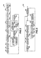
- FIG. 7 is a block diagram of an embodiment employing single-point processing in a network environment.
- FIG. 8 is a block diagram of an embodiment employing on-site processing in a networked environment.
- FIG. 9 is a block diagram of an embodiment of a scalable multiplexing facility.
- FIG. 1 Illustrates a display of a spatial multiplex video picture frame 100 made up of individual picture frames 102 .
- the spatial .multiplex video picture frame 100 includes sixteen picture frames 102 of individual people participating in a videoconference where the picture frames 102 form a mosaic pattern. Because each participant is always in view, the spatial multiplex video picture frame 100 is referred to as a continuous presence display. All will be discussed below, each individual picture frame 102 of the spatial multiplex video picture frame 100 is initially a normal picture frame 104 that may be displayed in full size on a display screen.
- the picture frame 104 may be represented as data that is encoded and segmented in various ways.
- the picture frame 104 may have been transmitted in a quarter-size common image format (QCIF) indicating a pixel resolution of 16 ⁇ 144.
- QCIF quarter-size common image format
- the spatial multiplex video picture frame 100 is decoded as a 4CIF picture indicating a resolution of 704 ⁇ 576 because it contains sixteen QCIFs where four QCIFs form a CIF size image.
- the multiplexed image may contain 64 individual QCIF picture frames and therefore have a 16CIF size.
- the group of blocks format 110 is one alternative for segmenting and encoding the picture frame 104 .
- the picture frame 104 of the group of blocks format 110 includes one or more rows of picture components known as groups of blocks 124 . In the example, shown, the QCIF frame 104 has three rows of groups of blocks.
- a picture header 122 is also included. The picture header provides information to a decoder when the picture frame 104 is to be displayed in full size and tells the decoder that the picture frame 104 has a group of blocks format 110 .
- Each row 124 is made up of an array 112 of macroblocks 128 that define the luminance and chrominance of the picture frame 104 .
- Each row 124 also includes a header 126 that tells the decoder the position within the picture frame 104 where the row of group of blocks 124 belongs.
- the group of blocks 124 has two rows of macroblocks 128 because it is intended for the picture frame 104 to be displayed with 404 to 800 total lines. In reality, a group of blocks 124 will have many more macroblocks 128 per row than those shown in FIG. 1 .
- the group of blocks format defined by the H.263 standard require that the row 124 always extends to the full width of the picture. Therefore, a 20 direct remapping of a group of blocks format 110 to a spatial multiplex video picture frame 100 is not possible because the spatial multiplex video picture frame 100 requires individual frames to have a width that may be less than the full width of the picture. In the videoconferencing context, several participants may need to be displayed across the width of the picture as shown in FIG. 1 , and a group of blocks format 110 does not permit such remapping.
- the slice format 106 is more flexible and does not require each slice to maintain the full width of the picture.
- the slice format 106 includes one or more picture components known as slices n6 that may or 30 may not extend across the full width of the picture, and a picture header 114 that specifies to the decoder that the picture frame 104 has a slice format.
- Bach slice 116 is made up of a grouping 108 of macroblocks 120 .
- Each slice 116 also has a slice header 118 that indicates to the decoder the relative position of the slice in the picture 104 .
- the slice format 106 of the picture frame 104 allows the picture frame 104 to be multiplexed into the composite picture frame 100 ⁇ with minimal decoding.
- the spatial 5 multiplex video picture frame 100 may be created in a slice format 130 of many slices 134 corresponding to the slices 116 of the individual picture frames 102 forming the composite. As shown, the slices 134 have a width that is less than the picture width so that multiple slices 134 are provided for each row of slices of the picture.
- a new picture header 132 is also generated to indicate to the decoder that the picture frame 100 is of the slice format 130 and is of a 4CIF size, 16CTF size, and so on.
- the header, such as 118 , of each slice 134 is modified to properly position the slice within the spatial multiplex video picture frame 100 .
- FIG. 2 shows the picture layer syntax 200 that is made up of the picture header included at the beginning of each picture frame as well as the group of block layer or 15 slice layer.
- the picture layer syntax 200 includes a picture start code (PSC) 202 that signifies the beginning of a new picture frame.
- a temporal reference (TR) 204 follows in the bitstream and provides a value indicating the timing of display of the picture frame relative to a previous frame and the picture clock frequency.
- a PTYPE block 206 follows and provides information about the picture such as whether the source format of the picture frame is a quarter-size common image format (QCIF), a CIF format, or other.
- QCIF quarter-size common image format
- the picture layer syntax 200 may also include a PLUS HEADER block 208 that contains information about the picture frame, including whether the frame consists of groups of blocks or slices.
- a PQUANT block 210 provides quantizer information to configure the quantization parameters used by the decoder.
- An optional continuous presence multipoint (CPM) block 212 signals the use of continuous presence multipoint and video multiplex mode discussed above that permits multiple individual frames to be included in the bitstream. As discussed the CPM mode causes the individual frames to maintain their identities as individual frames and requires that they be individually decoded and then processed to form a single image.
- a picture sub-bitstream indicator (PSBI) 214 may be included if CPM mode is indicated. CPM mode may be implemented in junction with the logical operations of FIGS. 5, 6A and 6B to provide sub-bitstreams that are themselves multiplexed bitstreams, or CPM may be turned off if only the logical operations of FIGS. 5, 6A and 6B are desired for providing continuous presence video.
- PSBI picture sub-bitstream indicator
- a temporal reference for B-picture parts (TRB) 216 may be included if a PB-frame is indicated by the PTYPE block 204 or PLUS HEADER block 208 .
- a DBQUANT block 218 may also be included if a PB-frame is indicated to indicate the relation of the BQUANT quantization parameter used for B-picture parts in relation to the QUANT quantization parameter used or P-picture parts.
- a PEI block 220 includes a bit that signals the presence of the supplemental enhancement information (PSUPP) block 222 .
- PSUPP block 222 defines extended capabilities for picture decoding.
- the group of blocks (GOB) layer 24 or slice layer 226 then follows in the bitstream.
- the GOB layer 224 contains each group of block of the picture frame and is discussed in more detail in FIG. 3 .
- Slice layer 226 contains each slice of the picture frame and is discussed in more detail in FIG. 4 .
- the ESTUF block 228 is included to provide mandatory byte alignment in the bitstrearn.
- the end of sequence (BOB) block 234 may be included to signal the end of the sequence of group of blocks or slices.
- the end of sub-bitstream sequence (EOSBS) block 230 may be included to indicate an end of a sub-bitstream when in CPM mode.
- An ending sub-bitstream indicator (ESBI) block 232 is included to provide the sub-bitstream number of the last sub-bitstream.
- the PSTUF block 236 is included to provide byte alignment for the PSC of the next picture frame.
- FIG. 3 shows the group of blocks layer syntax 300 that is made up of the component header and the macroblocks of the array fanning a group of blocks and that would be found in each group of blocks of the group of blocks layer 224 of FIG. 2 .
- a GSTUF block 302 is included to provide byte alignment for a group of blocks start code (GBSC) 304 .
- the GBSC 304 indicates to the decoder the start of a group of blocks.
- a group number (GN) block 306 indicates the group of block number that defines the position of the group of blocks in the picture frame.
- a GOB sub-bitstream indicator (GSBI) 308 may be included when in CPM mode to indicate the sub-bitstream number.
- a GOB frame ID (GFID) 310 is included to indicate the particular frame that the group of blocks corresponds to GQUANT block 312 provides quantizer information to control the quantization parameters of the decoder.
- a temporal reference indicator (TRI) block 314 is included to indicate the presence of a temporal reference when operating in a reference picture mode.
- a temporal reference (TR) block 316 is included to provide a value indicating the timing of display of the group of blocks relative to a previous group of blocks and the picture clock frequency.
- TRPI temporal reference for prediction indication
- TRP temporal reference for prediction field
- the TRP field 320 indicates the temporal reference to be used for prediction of the encoding.
- a back channel message indication (BCI) field 322 is included to indicate whether a message is to be delivered from the decoder back to the encoder regarding conditions of the received coded stream.
- a back channel message (BCM) layer 324 contains a message that is returned from a decoder to an encoder in order to tell whether forward-channel data was correctly decoded or not.
- a macroblock (MB) layer 326 contains a macroblock header and the macroblock data for the group of blocks.
- FIG. 4 shows the slice layer syntax 400 that is made up of the component header and the macroblocks of the array forming a slice and that would be found in each slice of the slice layer 226 of FIG. 2 .
- An SSTUF block 402 is included to provide byte alignment for a slice start code (SSC) block 404 indicating the beginning of a slice.
- a first slice emulation prevention bit (SEPB 1 ) 406 is included to prevent start code emulation after the SSC block 404 .
- SEPB 1 slice emulation prevention bit
- SEPB 1 slice sub-bitstream indicator
- SSBI slice sub-bitstream indicator
- a macroblock address (MBA) field 410 is included to indicate the first macroblock of the slice as counted from the beginning of the picture in scanning order to set the position of each slice in the picture frame.
- a second slice emulation prevention bit (SEPB 2 ) block 412 is also included to prevent start code emulation after the MBA field 410 .
- An SQUANT block 414 is included to provide quantizer information that controls the quantization parameters of the decoder.
- a slice width indication (SWI) block 416 is provided to indicate the width of the current rectangular slice whose first macroblock is specified by the MBA field 410 .
- a third slice emulation prevention bit (SEPB 3 ) 418 is included to prevent start code emulation after the SWI block 416 .
- a slice frame ID (GFID) 420 is included to indicate the particular picture frame that the slice corresponds to.
- the TRI field 422 , TR field 424 , TRPI field 4261 TRP field . 428 , BCI field 430 , BCM layer 432 , and MB layer 434 are identical to the fields of FIG. 3 that go by the same name.
- the operational flow of the process 500 for multiplexing individual picture frames containing the GOB syntax 300 or the slice syntax 400 into a single picture frame is shown in FIG. 5 .
- the single picture frames are originating from encoder devices and are being processed by one or more decoder devices after transfer, such as through a network medium as shown in the systems of FIGS. 7 and 8 .
- the process 500 begins at call operation 502 where the two devices passing the picture data establish a common mode of operation suitable for generating continuous presence video.
- the common mode of operation includes a consistent usage of header information so that, for example, back channel messaging is employed between the encoder and decoder or other enhanced capabilities are realized.
- start operation 504 causes one device of the connection to broadcast a start indicator that allows synchronization of transmission of the individual picture frames from the various sources, such as the remote locations of the videoconference.
- header operation 506 reads the picture layer header, such as shown in FIG. 2 , for each individual picture frame and discards them. This requires that only the picture header be decoded.
- a single new picture layer header that applies to the spatial multiplex video picture frame is created and encoded at header operation 506 .
- the single new picture layer header provides in the PTYPE field 206 an indication that the spatial multiplex video picture frame is of a size capable of including the number of individual frames being multiplexed.
- the PLUS HEADER field 208 of the new picture header is configured to indicate a rectangular slice format.
- the component header of one of the individual frames is interpreted at read operation 508 in preparation for subsequent processing discussed below including conversion lo a slice format and repositioning within the multiplexed image.
- Query operation 510 detects whether the picture header read in header operation 506 for the current picture frame indicates a group of blocks format. If a group of blocks format is detected, then conversion operation 512 converts the group of blocks headers into slice headers. Conversion operation 512 is discussed in greater detail below with reference to FIGS. 6A and 6B . If a group of blocks format is not detected, then the conversion operation 512 is skipped since a slice format is already present in the picture frame.
- macroblock operation 514 alters the MBA 410 within each slice of each picture frame to position the slice within a particular region of the spatial multiplex video picture frame. For example, one individual picture frame must go in the top left-hand corner of the multiplexed picture so the top-leftmost slice of that picture frame is given an MBA 410 corresponding to the top left-hand corner position.
- the component header is also re-encoded at this operation after the MBA 410 has been altered.
- the slice is then inserted into the proper location in the continuous presence picture stream by concatenating the bits of the slice with the bits already present in the picture stream ‘including the new picture header at stream operation 516 .
- the picture stream may be delivered as it is being generated at transmit operation 518 wherein the current slice is written to an output buffer and then transmitted to a network interface.
- query operation 520 After writing the slice to the output buffer, query operation 520 detects whether the last slice was the end of the continuous presence or spatial multiplex video picture frame. If it was not the last slice of the multiplexed frame, then flow returns to read operation 508 where the header of the next group of blocks or slice to be included in the spatial multiplex video picture frame is read. If query operation 520 determines that the last slice was the end of the spatial multiplex video picture frame, then flow returns to header operation 506 wherein the picture headers for the next set of individual picture frames are read and discarded.
- FIGS. 6A and 6B show the operational flow of the conversion operation 512 .
- Conversion operation 512 begins at alignment operation 602 where the GSTIJF field of the GOB syntax 300 is converted to an SSTUF field of the slice syntax 400 by adjusting the length of the stuff code to provide byte alignment of the next code element.
- start code operation 604 the GBSC 304 is maintained because it is already identical to the SSC 404 needed in the slice syntax 400 .
- the SEPB 1 406 is inserted into the bitstream to later prevent start code emulation when being decoded.
- Translation operation 608 converts the GSBI 308 to the SSBI 408 .
- GSBI ‘001 becomes SSBI ‘1001’
- GSBI ‘011 becomes SSBI 11010’
- GSBI ‘10’ becomes SSBI ‘1011’
- GSBI ‘11’ becomes SSBI ‘1101’.
- the GN 306 is replaced by an MBA 410 chosen to place the slice in its designated location within the composite picture frame resulting from multiplexing the individual picture frame bitstreams.
- Prevention operation 612 places a SEPB 2 into the bitstream to prevent start code emulation.
- GQUANT is maintained in the bitstream after SEPB 2 because GQUANT is already identical to SQUANT 414 .
- Slice operation 616 sets the width of the slice, or SWI 416 , to the width of the GOB in terms of the number of macroblocks. This is possible because the slice structure selection (SSS) field (not shown) of the PLUS HEADER field 208 of the picture syntax 200 of FIG. 2 has been set to the rectangular slice mode in header operation 506 of FIG. 5 .
- Prevention operation 618 then inserts a SEPB 3 into the bitstream to prevent start code emulation when the slice is decoded.
- the GFID 310 is maintained in the bitstream after SEPB 3 because it is already identical to GFID 420 .
- substitute operation 622 all remaining portions of the GOB syntax 300 are maintained in the bitstream because they are also identical to the remaining portions of the slice syntax 400 .
- FIG. 7 shows one network environment for hosting a continuous presence videoconference.
- a server 702 communicates through bi-directional communication channels 716 with client devices 704 , 706 , 708 , and 710 .
- Each client device such as a personal computer or special-purpose videoconferencing module is linked to a camera 712 or other video source and a video display 714 .
- the client devices transmit sequences of encoded picture frames produced by the camera 712 or other video source to the server 702 through the communication channels 716 .
- the server 702 then employs the processes of FIGS. 5, 6A and 6B to combine all of the encoded picture frames into an encoded spatial multiplex video picture frame.
- the server 702 then transmits the spatial multiplex video picture frame back through the communications channels 716 to the client devices where it is decoded and displayed on each display screen 714 .
- the client devices may include encoder and decoder processing but do not need to include the multiplexing processing discussed above.
- each individual frame to be included in the multiplexed frame through the processes of FIGS. 5, 6A and 6B do not have to be of the same size, such that one frame may occupy more screen area than others.
- the frame showing the person currently speaking in a videoconference may be enlarged relative to frames showing other participants.
- negotiation between participating devices can be established such that mode switching can occur to permit one or more participants to provide one image size (e,g., QCIF) while other participants provide a different image size (e.g., C).
- the server 702 may customize each videostream being returned to each client device 704 , 706 , 708 , and 710 , such as by removing the frame provided by the recipient client device from the spatial multiplex being returned or creating the spatial multiplex from some other subset.
- the communication channel between the client devices 704 , 706 , 708 , and 710 and the server 702 can be of various forms known in the art such as conventional dial-up connections, asymmetric digital subscriber lines (ADSL), cable modem lines, Ethernet, and/or any combination.
- An Internet Service Provider (ISP) (not shown) may be provided between the server 702 and each client device or the server 702 may itself act as an ISP.
- the transmissions through a given channel 716 are asymmetric due to one picture frame being transmitted to the server 702 from each client device while the server 702 transmits a configuration of picture frames forming the multiplexed bitstream back to each client device. Therefore, ADSL is well suited to picture frame transfer in this network configuration since ADSL typically provides a much greater bandwidth from the network to the client device.
- FIG. 8 shows an alternative network configuration where each client device 802 , 804 , 806 , and 808 has its own processing device performing the operations of FIGS. 5, 6A and 6B .
- Each client device is linked to a camera 810 or other video source and a display 812 .
- a bi-directional communication path 814 interconnects each client device to the others.
- the bi-directional communication paths 814 can also be of various forms known in the art such as conventional dial-up connections, asymmetric digital subscriber lines (ADSL), cable modem lines, Ethernet, and/or any combination.
- ADSL asymmetric digital subscriber lines
- One or .more ISPs may facilitate transfer between a pair of client devices.
- Each client device generates an encoded picture frame sequence that is transmitted to the other client devices.
- each client device receives an encoded picture frame from the other client devices.
- the client device may then perform the multiplexing operations discussed above to create the spatial multiplex video picture frame that is displayed.
- the spatial multiplex video picture frame will be displayed allows each client device to have control over the spatial multiplex video picture frame it will display. For example, the client device can choose to exclude certain picture frames or alter the displayed size of particular picture frames. In a videoconference, the client device may choose to eliminate the picture frame that it generates and sends to others from the spatial multiplex video picture frame that it generates and displays. Because each client device performs the multiplexing operations, the communication paths 814 carry only the individual picture frame sequences generated by each sending client device rather than spatial multiplex video picture frame sequences.
- FIG. 9 shows an example of a scalable multi-point conferencing facility 900 .
- the facility includes a packet switch 902 ; such as a multi-gigabit Ethernet switch, linked to several processing modules, such as single board computers (SBCs) 904 , 906 , and 908 .
- SBC single board computers
- An SBC generally refers to a computer having a single circuit board including memory, magnetic storage, and a processor for executing a logical process such as those of FIGS. 5, 6A and 6B .
- the processing modules may include general-purpose programmable processors or dedicated logic circuits depending upon the performance necessary. Because the operations of FIGS. 5, 6A, and 6B to be performed by the processing modules require only decoding of header information, programmable processors are adequate for continuous presence processing in real time for most implementations.
- the processing modules are linked to the packet switch 902 through high-speed serial interfaces 910 , such as Fast/Gigabit Ethernet.
- the packet switch 902 receives encoded picture frame sequences from client devices, such as discussed with reference to FIG. 7 , but possibly from several videoconferencing sessions.
- the packet switch 902 may then send all picture frame sequences corresponding to a particular videoconference to one of the processing modules 904 ) 906 , or 908 .
- the processing module multiplexes the picture frames to generate a spatial multiplex video picture frame and sends the spatial multiplex video picture frame sequence back to the packet switch 902 .
- the packet switch 902 then delivers the spatial multiplex video picture frame sequence back to client devices of the particular videoconference.
- the scalable multi-point conferencing facility 900 can provide multiplexing services for multiple videoconference groups simultaneously. As the number of videoconference groups at any given time increases or decreases, the processing modules employed by the packet switch 902 can be added or removed from active service and made available for other duties when not needed by packet switch 902 .
Abstract
Description
Claims (20)
Priority Applications (1)
| Application Number | Priority Date | Filing Date | Title |
|---|---|---|---|
| US14/518,251 US9554165B2 (en) | 2001-09-19 | 2014-10-20 | Minimal decoding method for spatially multiplexing digital video pictures |
Applications Claiming Priority (5)
| Application Number | Priority Date | Filing Date | Title |
|---|---|---|---|
| US09/955,607 US6956600B1 (en) | 2001-09-19 | 2001-09-19 | Minimal decoding method for spatially multiplexing digital video pictures |
| US11/202,914 US7518630B2 (en) | 2001-09-19 | 2005-08-12 | Minimal decoding method for spatially multiplexing digital video pictures |
| US12/423,649 US8179420B2 (en) | 2001-09-19 | 2009-04-14 | Minimal decoding method for spatially multiplexing digital video pictures |
| US13/453,055 US8872881B2 (en) | 2001-09-19 | 2012-04-23 | Minimal decoding method for spatially multiplexing digital video pictures |
| US14/518,251 US9554165B2 (en) | 2001-09-19 | 2014-10-20 | Minimal decoding method for spatially multiplexing digital video pictures |
Related Parent Applications (1)
| Application Number | Title | Priority Date | Filing Date |
|---|---|---|---|
| US13/453,055 Continuation US8872881B2 (en) | 2001-09-19 | 2012-04-23 | Minimal decoding method for spatially multiplexing digital video pictures |
Publications (3)
| Publication Number | Publication Date |
|---|---|
| US20150103251A1 US20150103251A1 (en) | 2015-04-16 |
| US20160249077A9 US20160249077A9 (en) | 2016-08-25 |
| US9554165B2 true US9554165B2 (en) | 2017-01-24 |
Family
ID=25497071
Family Applications (5)
| Application Number | Title | Priority Date | Filing Date |
|---|---|---|---|
| US09/955,607 Expired - Lifetime US6956600B1 (en) | 2001-09-19 | 2001-09-19 | Minimal decoding method for spatially multiplexing digital video pictures |
| US11/202,914 Expired - Lifetime US7518630B2 (en) | 2001-09-19 | 2005-08-12 | Minimal decoding method for spatially multiplexing digital video pictures |
| US12/423,649 Expired - Lifetime US8179420B2 (en) | 2001-09-19 | 2009-04-14 | Minimal decoding method for spatially multiplexing digital video pictures |
| US13/453,055 Expired - Fee Related US8872881B2 (en) | 2001-09-19 | 2012-04-23 | Minimal decoding method for spatially multiplexing digital video pictures |
| US14/518,251 Expired - Lifetime US9554165B2 (en) | 2001-09-19 | 2014-10-20 | Minimal decoding method for spatially multiplexing digital video pictures |
Family Applications Before (4)
| Application Number | Title | Priority Date | Filing Date |
|---|---|---|---|
| US09/955,607 Expired - Lifetime US6956600B1 (en) | 2001-09-19 | 2001-09-19 | Minimal decoding method for spatially multiplexing digital video pictures |
| US11/202,914 Expired - Lifetime US7518630B2 (en) | 2001-09-19 | 2005-08-12 | Minimal decoding method for spatially multiplexing digital video pictures |
| US12/423,649 Expired - Lifetime US8179420B2 (en) | 2001-09-19 | 2009-04-14 | Minimal decoding method for spatially multiplexing digital video pictures |
| US13/453,055 Expired - Fee Related US8872881B2 (en) | 2001-09-19 | 2012-04-23 | Minimal decoding method for spatially multiplexing digital video pictures |
Country Status (2)
| Country | Link |
|---|---|
| US (5) | US6956600B1 (en) |
| WO (1) | WO2003026300A1 (en) |
Families Citing this family (42)
| Publication number | Priority date | Publication date | Assignee | Title |
|---|---|---|---|---|
| US20020122491A1 (en) * | 2001-01-03 | 2002-09-05 | Marta Karczewicz | Video decoder architecture and method for using same |
| EP1454486A4 (en) * | 2001-12-04 | 2009-03-25 | Polycom Inc | Method and an apparatus for mixing compressed video |
| US7693220B2 (en) * | 2002-01-03 | 2010-04-06 | Nokia Corporation | Transmission of video information |
| JP3909704B2 (en) * | 2003-04-04 | 2007-04-25 | ソニー株式会社 | Editing system |
| US20050008240A1 (en) * | 2003-05-02 | 2005-01-13 | Ashish Banerji | Stitching of video for continuous presence multipoint video conferencing |
| KR100492567B1 (en) * | 2003-05-13 | 2005-06-03 | 엘지전자 주식회사 | Http-based video streaming apparatus and method for a mobile communication system |
| CN1571508B (en) * | 2003-07-19 | 2010-05-12 | 华为技术有限公司 | A method for implementing multi-frame |
| US8170096B1 (en) * | 2003-11-18 | 2012-05-01 | Visible World, Inc. | System and method for optimized encoding and transmission of a plurality of substantially similar video fragments |
| US20060075449A1 (en) * | 2004-09-24 | 2006-04-06 | Cisco Technology, Inc. | Distributed architecture for digital program insertion in video streams delivered over packet networks |
| JP2006222648A (en) * | 2005-02-09 | 2006-08-24 | Sony Corp | Decoding method and decoding device, and program therefor |
| US20060271990A1 (en) | 2005-05-18 | 2006-11-30 | Rodriguez Arturo A | Higher picture rate HD encoding and transmission with legacy HD backward compatibility |
| GB2429593A (en) | 2005-08-26 | 2007-02-28 | Electrosonic Ltd | Data compressing using a wavelet compression scheme |
| US7680047B2 (en) * | 2005-11-22 | 2010-03-16 | Cisco Technology, Inc. | Maximum transmission unit tuning mechanism for a real-time transport protocol stream |
| US7707247B2 (en) * | 2006-04-20 | 2010-04-27 | Cisco Technology, Inc. | System and method for displaying users in a visual conference between locations |
| US8326927B2 (en) * | 2006-05-23 | 2012-12-04 | Cisco Technology, Inc. | Method and apparatus for inviting non-rich media endpoints to join a conference sidebar session |
| US8369419B2 (en) * | 2006-06-16 | 2013-02-05 | Via Technologies, Inc. | Systems and methods of video compression deblocking |
| US20080043090A1 (en) * | 2006-08-07 | 2008-02-21 | Yair Wiener | Systems and methods for optimizing video processing |
| US8358763B2 (en) * | 2006-08-21 | 2013-01-22 | Cisco Technology, Inc. | Camping on a conference or telephony port |
| US8121277B2 (en) * | 2006-12-12 | 2012-02-21 | Cisco Technology, Inc. | Catch-up playback in a conferencing system |
| US8542266B2 (en) | 2007-05-21 | 2013-09-24 | Polycom, Inc. | Method and system for adapting a CP layout according to interaction between conferees |
| US8305387B2 (en) * | 2007-09-07 | 2012-11-06 | Texas Instruments Incorporated | Adaptive pulse-width modulated sequences for sequential color display systems |
| US8457214B2 (en) | 2007-09-10 | 2013-06-04 | Cisco Technology, Inc. | Video compositing of an arbitrary number of source streams using flexible macroblock ordering |
| US20100225655A1 (en) * | 2009-03-06 | 2010-09-09 | Microsoft Corporation | Concurrent Encoding/Decoding of Tiled Data |
| US20100226441A1 (en) * | 2009-03-06 | 2010-09-09 | Microsoft Corporation | Frame Capture, Encoding, and Transmission Management |
| US8638337B2 (en) | 2009-03-16 | 2014-01-28 | Microsoft Corporation | Image frame buffer management |
| US9516272B2 (en) * | 2010-03-31 | 2016-12-06 | Polycom, Inc. | Adapting a continuous presence layout to a discussion situation |
| US8427520B2 (en) * | 2010-12-02 | 2013-04-23 | Polycom, Inc. | Removing a self image from a continuous presence video image |
| KR101251755B1 (en) * | 2011-04-22 | 2013-04-05 | 권기훈 | Method for Resizing of Screen Image of Video Conference System and System thereof |
| US9219889B2 (en) * | 2011-12-14 | 2015-12-22 | Avigilon Fortress Corporation | Multichannel video content analysis system using video multiplexing |
| US9007426B2 (en) | 2012-10-04 | 2015-04-14 | Blackberry Limited | Comparison-based selection of video resolutions in a video call |
| AU2013361214B2 (en) * | 2012-12-19 | 2018-06-14 | SocialVenu, Inc. | Image capture, processing and delivery at group events |
| US9854261B2 (en) * | 2015-01-06 | 2017-12-26 | Microsoft Technology Licensing, Llc. | Detecting markers in an encoded video signal |
| US9992252B2 (en) | 2015-09-29 | 2018-06-05 | Rgb Systems, Inc. | Method and apparatus for adaptively compressing streaming video |
| US10271069B2 (en) * | 2016-08-31 | 2019-04-23 | Microsoft Technology Licensing, Llc | Selective use of start code emulation prevention |
| JP7212611B2 (en) * | 2017-02-27 | 2023-01-25 | パナソニック インテレクチュアル プロパティ コーポレーション オブ アメリカ | Image delivery method, image display method, image delivery device and image display device |
| US10567703B2 (en) | 2017-06-05 | 2020-02-18 | Cisco Technology, Inc. | High frame rate video compatible with existing receivers and amenable to video decoder implementation |
| CN109429073B (en) * | 2017-09-01 | 2021-07-02 | 杭州海康威视数字技术股份有限公司 | Method, device and system for sending multimedia data and playing multimedia data |
| KR20220119675A (en) | 2020-01-09 | 2022-08-30 | 텔레폰악티에볼라겟엘엠에릭슨(펍) | image header present |
| CN113422962B (en) * | 2020-12-30 | 2022-07-19 | 北京所思信息科技有限责任公司 | Video coding method and coder |
| CN113422963B (en) * | 2020-12-30 | 2022-07-19 | 北京所思信息科技有限责任公司 | Video decoding method and decoder |
| US11743440B2 (en) | 2021-04-19 | 2023-08-29 | Apple Inc. | Transmission and consumption of multiple image subframes via superframe |
| DE202022100984U1 (en) | 2021-10-14 | 2022-03-30 | Arktis It Solutions Gmbh | Courtroom Media System |
Citations (19)
| Publication number | Priority date | Publication date | Assignee | Title |
|---|---|---|---|---|
| US5453780A (en) * | 1994-04-28 | 1995-09-26 | Bell Communications Research, Inc. | Continous presence video signal combiner |
| WO1997036425A1 (en) | 1996-03-28 | 1997-10-02 | British Telecommunications Public Limited Company | Video processing |
| US5764277A (en) | 1995-11-08 | 1998-06-09 | Bell Communications Research, Inc. | Group-of-block based video signal combining for multipoint continuous presence video conferencing |
| US5995146A (en) | 1997-01-24 | 1999-11-30 | Pathway, Inc. | Multiple video screen display system |
| EP0987897A2 (en) | 1998-08-25 | 2000-03-22 | Matsushita Electric Industrial Co., Ltd. | Moving picture synthesizing device |
| US6049531A (en) | 1997-07-14 | 2000-04-11 | At&T Corp | Real-time multimedia conferencing over an ATM network using an intelligent ATM ADSL modem and ADSL access |
| US6141062A (en) | 1998-06-01 | 2000-10-31 | Ati Technologies, Inc. | Method and apparatus for combining video streams |
| US6181824B1 (en) | 1997-01-23 | 2001-01-30 | Hitachi, Ltd. | Code string editing apparatus, picture coded signal decoding apparatus and moving picture coded signal decoding apparatus |
| JP2001069474A (en) | 1999-08-25 | 2001-03-16 | Nec Corp | Multi-point controller and video display method used for it |
| US6285661B1 (en) | 1998-01-28 | 2001-09-04 | Picturetel Corporation | Low delay real time digital video mixing for multipoint video conferencing |
| US6332003B1 (en) * | 1997-11-11 | 2001-12-18 | Matsushita Electric Industrial Co., Ltd. | Moving image composing system |
| US6590604B1 (en) | 2000-04-07 | 2003-07-08 | Polycom, Inc. | Personal videoconferencing system having distributed processing architecture |
| US6606112B1 (en) | 2000-03-16 | 2003-08-12 | Tandberg Telecom As | Composite-video generation from different-rate constituents |
| US6614900B1 (en) | 1999-07-22 | 2003-09-02 | Alcatel Networks Corporation Societe Par Actens De Regime Federal De Respaux Alcatel | Method and apparatus for processing call signaling messages |
| US6658618B1 (en) | 1999-09-02 | 2003-12-02 | Polycom, Inc. | Error recovery method for video compression coding using multiple reference buffers and a message channel |
| US6683909B1 (en) | 2000-03-16 | 2004-01-27 | Ezenial Inc. | Macroblock parsing without processing overhead |
| US20040109610A1 (en) * | 2002-08-26 | 2004-06-10 | Taku Kodama | Image processing apparatus for compositing images |
| US6775241B1 (en) | 1997-09-25 | 2004-08-10 | Freescale Semiconductor, Inc. | Method and apparatus for configuring a communication system |
| US6934278B1 (en) | 1998-12-28 | 2005-08-23 | Unisys Corporation | Multimedia interface for a communications network |
-
2001
- 2001-09-19 US US09/955,607 patent/US6956600B1/en not_active Expired - Lifetime
-
2002
- 2002-09-11 WO PCT/US2002/028975 patent/WO2003026300A1/en not_active Application Discontinuation
-
2005
- 2005-08-12 US US11/202,914 patent/US7518630B2/en not_active Expired - Lifetime
-
2009
- 2009-04-14 US US12/423,649 patent/US8179420B2/en not_active Expired - Lifetime
-
2012
- 2012-04-23 US US13/453,055 patent/US8872881B2/en not_active Expired - Fee Related
-
2014
- 2014-10-20 US US14/518,251 patent/US9554165B2/en not_active Expired - Lifetime
Patent Citations (20)
| Publication number | Priority date | Publication date | Assignee | Title |
|---|---|---|---|---|
| US5453780A (en) * | 1994-04-28 | 1995-09-26 | Bell Communications Research, Inc. | Continous presence video signal combiner |
| US5764277A (en) | 1995-11-08 | 1998-06-09 | Bell Communications Research, Inc. | Group-of-block based video signal combining for multipoint continuous presence video conferencing |
| WO1997036425A1 (en) | 1996-03-28 | 1997-10-02 | British Telecommunications Public Limited Company | Video processing |
| US6181824B1 (en) | 1997-01-23 | 2001-01-30 | Hitachi, Ltd. | Code string editing apparatus, picture coded signal decoding apparatus and moving picture coded signal decoding apparatus |
| US5995146A (en) | 1997-01-24 | 1999-11-30 | Pathway, Inc. | Multiple video screen display system |
| US6049531A (en) | 1997-07-14 | 2000-04-11 | At&T Corp | Real-time multimedia conferencing over an ATM network using an intelligent ATM ADSL modem and ADSL access |
| US6775241B1 (en) | 1997-09-25 | 2004-08-10 | Freescale Semiconductor, Inc. | Method and apparatus for configuring a communication system |
| US6332003B1 (en) * | 1997-11-11 | 2001-12-18 | Matsushita Electric Industrial Co., Ltd. | Moving image composing system |
| US6285661B1 (en) | 1998-01-28 | 2001-09-04 | Picturetel Corporation | Low delay real time digital video mixing for multipoint video conferencing |
| US6141062A (en) | 1998-06-01 | 2000-10-31 | Ati Technologies, Inc. | Method and apparatus for combining video streams |
| EP0987897A2 (en) | 1998-08-25 | 2000-03-22 | Matsushita Electric Industrial Co., Ltd. | Moving picture synthesizing device |
| US6934278B1 (en) | 1998-12-28 | 2005-08-23 | Unisys Corporation | Multimedia interface for a communications network |
| US6614900B1 (en) | 1999-07-22 | 2003-09-02 | Alcatel Networks Corporation Societe Par Actens De Regime Federal De Respaux Alcatel | Method and apparatus for processing call signaling messages |
| JP2001069474A (en) | 1999-08-25 | 2001-03-16 | Nec Corp | Multi-point controller and video display method used for it |
| US6441841B1 (en) | 1999-08-25 | 2002-08-27 | Nec Corporation | Picture combining technique in multipoint control unit |
| US6658618B1 (en) | 1999-09-02 | 2003-12-02 | Polycom, Inc. | Error recovery method for video compression coding using multiple reference buffers and a message channel |
| US6606112B1 (en) | 2000-03-16 | 2003-08-12 | Tandberg Telecom As | Composite-video generation from different-rate constituents |
| US6683909B1 (en) | 2000-03-16 | 2004-01-27 | Ezenial Inc. | Macroblock parsing without processing overhead |
| US6590604B1 (en) | 2000-04-07 | 2003-07-08 | Polycom, Inc. | Personal videoconferencing system having distributed processing architecture |
| US20040109610A1 (en) * | 2002-08-26 | 2004-06-10 | Taku Kodama | Image processing apparatus for compositing images |
Non-Patent Citations (13)
| Title |
|---|
| Chen et al. "A Self-Governing Rate Buffer Control Strategy for Pseudoconstant Bit Rate Video Coding", IEEE Trans on Image Processing, 2(1):50-59 (1993). |
| Gaylord, W.J. "Coding for Multipoint Video Conferencing" BellSouth Telecommunications Presentation, EIA Digital Video Workshop (1992). |
| Gharavi, H. "Differential Sub-Band Coding of Video Signals", ICASSP, Scotland, pp. 1819-1822 (1989). |
| Huang et al. "Block Quantization of Correlated Gaussian Random Variables", IEEE Transactions on Comm Sys, D CS-11(3):289-296 (1963). |
| Lau et al. "Receiver Buffer Control for Variable Bit-Rate Real-Time Video", Proc Inll Conf on Communications, 1:544-550 (1992). |
| Lei et al. "Video Bridging Based on H.261 Standard", IEEE Trans on Circuits and Systems for Video TEchnology, 4 (4):425-437 (1994). |
| Loui et al. "Video Combining for Multipoint Videoconferencing", New Jersey, IS&T 48th Annual Conf Proceedings, Bel Communications Research, pp. 48-50 (1995). |
| Ramstad, T.A. "Considerations on Quantization and Dynamic Bit-Allocated Subband Coders", ICASSP, Japan, pp. 841-844 (1986). |
| Segall, A. "Bit Allocation and Encoding for Vector Sources", IEEE Transactions on Information Theory, IT-22 D (2):162-169 (1976). |
| Smith et al. "Analysis/Synthesis Techniques for Subband Image Coding", IEEE Trans on Acoustics, Speech, Signal Processing, ASSP-38(8):1446-1456 (1990). |
| Tzou et al. "An Intelligent Rate Control for an Intrafield Subband HDTV Coder", Proc Intl Conf Symposium on Circuits and Electronics, 1:284-287 (1991). |
| Vajdyanthan, P.P. "Quadrature Mirror Filter Banks, M-Bank Extensions and Perfect-Reconstructions Techniques", IEEE ASSP Magazine, 4:4-20 (1987). |
| Woods et al. "Subband Coding of Images", IEEE Trans on Acoustics, Speech, Signal Processing, ASSP-34 (5):1278-1288 (1986). |
Also Published As
| Publication number | Publication date |
|---|---|
| US8872881B2 (en) | 2014-10-28 |
| US20050286640A1 (en) | 2005-12-29 |
| US20160249077A9 (en) | 2016-08-25 |
| US7518630B2 (en) | 2009-04-14 |
| US20090207844A1 (en) | 2009-08-20 |
| US6956600B1 (en) | 2005-10-18 |
| US20150103251A1 (en) | 2015-04-16 |
| WO2003026300A1 (en) | 2003-03-27 |
| US20120262630A1 (en) | 2012-10-18 |
| US8179420B2 (en) | 2012-05-15 |
Similar Documents
| Publication | Publication Date | Title |
|---|---|---|
| US9554165B2 (en) | Minimal decoding method for spatially multiplexing digital video pictures | |
| AU2002355089B2 (en) | Method and apparatus for continuously receiving frames from a pluarlity of video channels and for alternatively continuously transmitting to each of a plurality of participants in a video conference individual frames containing information concerning each of said video channels | |
| US5453780A (en) | Continous presence video signal combiner | |
| US7616591B2 (en) | Video conferencing system | |
| US5764277A (en) | Group-of-block based video signal combining for multipoint continuous presence video conferencing | |
| JP4384170B2 (en) | How to achieve multi-screen | |
| US8436889B2 (en) | System and method for videoconferencing using scalable video coding and compositing scalable video conferencing servers | |
| US8934553B2 (en) | Creation of composite images from a plurality of source streams | |
| US7830409B2 (en) | Split screen video in a multimedia communication system | |
| US20060146734A1 (en) | Method and system for low-delay video mixing | |
| AU2002355089A1 (en) | Method and apparatus for continuously receiving frames from a pluarlity of video channels and for alternatively continuously transmitting to each of a plurality of participants in a video conference individual frames containing information concerning each of said video channels | |
| CA2633366A1 (en) | System and method for videoconferencing using scalable video coding and compositing scalable video conferencing servers | |
| Gaglianello et al. | Montage: Continuous presence teleconferencing utilizing compressed domain video bridging | |
| Sun et al. | A coded-domain video combiner for multipoint continuous presence video conferencing | |
| Loui et al. | Coded-domain multipoint video bridging | |
| KR19990070821A (en) | A server that converts video of up to four participants into a single video stream in a video conferencing system. |
Legal Events
| Date | Code | Title | Description |
|---|---|---|---|
| AS | Assignment |
Owner name: BELLSOUTH INTELLECTUAL PROPERTY CORPORATION, DELAW Free format text: ASSIGNMENT OF ASSIGNORS INTEREST;ASSIGNOR:GAYLORD, WILLIAM J.;REEL/FRAME:034219/0608 Effective date: 20010910 |
|
| AS | Assignment |
Owner name: AT&T INTELLECTUAL PROPERTY I, L.P., GEORGIA Free format text: ASSIGNMENT OF ASSIGNORS INTEREST;ASSIGNOR:AT&T DELAWARE INTELLECTUAL PROPERTY, INC.;REEL/FRAME:037305/0144 Effective date: 20080630 Owner name: AT&T BLS INTELLECTUAL PROPERTY, INC., DELAWARE Free format text: CHANGE OF NAME;ASSIGNOR:AT&T INTELLECTUAL PROPERTY, INC.;REEL/FRAME:037311/0493 Effective date: 20070727 Owner name: AT&T INTELLECTUAL PROPERTY, INC., DELAWARE Free format text: CHANGE OF NAME;ASSIGNOR:BELLSOUTH INTELLECTUAL PROPERTY CORPORATION;REEL/FRAME:037311/0413 Effective date: 20070427 Owner name: AT&T DELAWARE INTELLECTUAL PROPERTY, INC., DELAWAR Free format text: CHANGE OF NAME;ASSIGNOR:AT&T BLS INTELLECTUAL PROPERTY, INC.;REEL/FRAME:037311/0497 Effective date: 20071101 |
|
| FEPP | Fee payment procedure |
Free format text: PAYOR NUMBER ASSIGNED (ORIGINAL EVENT CODE: ASPN); ENTITY STATUS OF PATENT OWNER: LARGE ENTITY |
|
| STCF | Information on status: patent grant |
Free format text: PATENTED CASE |
|
| MAFP | Maintenance fee payment |
Free format text: PAYMENT OF MAINTENANCE FEE, 4TH YEAR, LARGE ENTITY (ORIGINAL EVENT CODE: M1551); ENTITY STATUS OF PATENT OWNER: LARGE ENTITY Year of fee payment: 4 |