US9549780B2 - Steerable laser probe - Google Patents

Steerable laser probe Download PDF

Info

Publication number
US9549780B2
US9549780B2 US13/862,433 US201313862433A US9549780B2 US 9549780 B2 US9549780 B2 US 9549780B2 US 201313862433 A US201313862433 A US 201313862433A US 9549780 B2 US9549780 B2 US 9549780B2
Authority
US
United States
Prior art keywords
optic fiber
housing tube
actuation lever
flexible housing
actuation
Prior art date
Legal status (The legal status is an assumption and is not a legal conclusion. Google has not performed a legal analysis and makes no representation as to the accuracy of the status listed.)
Active, expires
Application number
US13/862,433
Other versions
US20130304048A1 (en
Inventor
Gregg D Scheller
Matthew N Zeid
Current Assignee (The listed assignees may be inaccurate. Google has not performed a legal analysis and makes no representation or warranty as to the accuracy of the list.)
Katalyst Surgical LLC
Original Assignee
Katalyst Surgical LLC
Priority date (The priority date is an assumption and is not a legal conclusion. Google has not performed a legal analysis and makes no representation as to the accuracy of the date listed.)
Filing date
Publication date
Application filed by Katalyst Surgical LLC filed Critical Katalyst Surgical LLC
Priority to US13/862,433 priority Critical patent/US9549780B2/en
Assigned to KATALYST SURGICAL, LLC reassignment KATALYST SURGICAL, LLC ASSIGNMENT OF ASSIGNORS INTEREST (SEE DOCUMENT FOR DETAILS). Assignors: SCHELLER, GREGG D, ZEID, MATTHEW N
Publication of US20130304048A1 publication Critical patent/US20130304048A1/en
Priority to US15/377,586 priority patent/US10307208B2/en
Application granted granted Critical
Publication of US9549780B2 publication Critical patent/US9549780B2/en
Priority to US16/385,058 priority patent/US11234766B2/en
Active legal-status Critical Current
Adjusted expiration legal-status Critical

Links

Images

Classifications

    • AHUMAN NECESSITIES
    • A61MEDICAL OR VETERINARY SCIENCE; HYGIENE
    • A61BDIAGNOSIS; SURGERY; IDENTIFICATION
    • A61B18/00Surgical instruments, devices or methods for transferring non-mechanical forms of energy to or from the body
    • A61B18/18Surgical instruments, devices or methods for transferring non-mechanical forms of energy to or from the body by applying electromagnetic radiation, e.g. microwaves
    • A61B18/20Surgical instruments, devices or methods for transferring non-mechanical forms of energy to or from the body by applying electromagnetic radiation, e.g. microwaves using laser
    • A61B18/22Surgical instruments, devices or methods for transferring non-mechanical forms of energy to or from the body by applying electromagnetic radiation, e.g. microwaves using laser the beam being directed along or through a flexible conduit, e.g. an optical fibre; Couplings or hand-pieces therefor
    • AHUMAN NECESSITIES
    • A61MEDICAL OR VETERINARY SCIENCE; HYGIENE
    • A61FFILTERS IMPLANTABLE INTO BLOOD VESSELS; PROSTHESES; DEVICES PROVIDING PATENCY TO, OR PREVENTING COLLAPSING OF, TUBULAR STRUCTURES OF THE BODY, e.g. STENTS; ORTHOPAEDIC, NURSING OR CONTRACEPTIVE DEVICES; FOMENTATION; TREATMENT OR PROTECTION OF EYES OR EARS; BANDAGES, DRESSINGS OR ABSORBENT PADS; FIRST-AID KITS
    • A61F9/00Methods or devices for treatment of the eyes; Devices for putting-in contact lenses; Devices to correct squinting; Apparatus to guide the blind; Protective devices for the eyes, carried on the body or in the hand
    • A61F9/007Methods or devices for eye surgery
    • A61F9/008Methods or devices for eye surgery using laser
    • A61F9/00821Methods or devices for eye surgery using laser for coagulation
    • A61F9/00823Laser features or special beam parameters therefor
    • AHUMAN NECESSITIES
    • A61MEDICAL OR VETERINARY SCIENCE; HYGIENE
    • A61BDIAGNOSIS; SURGERY; IDENTIFICATION
    • A61B18/00Surgical instruments, devices or methods for transferring non-mechanical forms of energy to or from the body
    • A61B2018/00571Surgical instruments, devices or methods for transferring non-mechanical forms of energy to or from the body for achieving a particular surgical effect
    • A61B2018/00589Coagulation
    • AHUMAN NECESSITIES
    • A61MEDICAL OR VETERINARY SCIENCE; HYGIENE
    • A61BDIAGNOSIS; SURGERY; IDENTIFICATION
    • A61B18/00Surgical instruments, devices or methods for transferring non-mechanical forms of energy to or from the body
    • A61B18/18Surgical instruments, devices or methods for transferring non-mechanical forms of energy to or from the body by applying electromagnetic radiation, e.g. microwaves
    • A61B18/20Surgical instruments, devices or methods for transferring non-mechanical forms of energy to or from the body by applying electromagnetic radiation, e.g. microwaves using laser
    • A61B18/22Surgical instruments, devices or methods for transferring non-mechanical forms of energy to or from the body by applying electromagnetic radiation, e.g. microwaves using laser the beam being directed along or through a flexible conduit, e.g. an optical fibre; Couplings or hand-pieces therefor
    • A61B2018/2238Surgical instruments, devices or methods for transferring non-mechanical forms of energy to or from the body by applying electromagnetic radiation, e.g. microwaves using laser the beam being directed along or through a flexible conduit, e.g. an optical fibre; Couplings or hand-pieces therefor with means for selectively laterally deflecting the tip of the fibre
    • AHUMAN NECESSITIES
    • A61MEDICAL OR VETERINARY SCIENCE; HYGIENE
    • A61BDIAGNOSIS; SURGERY; IDENTIFICATION
    • A61B18/00Surgical instruments, devices or methods for transferring non-mechanical forms of energy to or from the body
    • A61B18/18Surgical instruments, devices or methods for transferring non-mechanical forms of energy to or from the body by applying electromagnetic radiation, e.g. microwaves
    • A61B18/20Surgical instruments, devices or methods for transferring non-mechanical forms of energy to or from the body by applying electromagnetic radiation, e.g. microwaves using laser
    • A61B18/22Surgical instruments, devices or methods for transferring non-mechanical forms of energy to or from the body by applying electromagnetic radiation, e.g. microwaves using laser the beam being directed along or through a flexible conduit, e.g. an optical fibre; Couplings or hand-pieces therefor
    • A61B2018/2244Features of optical fibre cables, e.g. claddings
    • AHUMAN NECESSITIES
    • A61MEDICAL OR VETERINARY SCIENCE; HYGIENE
    • A61BDIAGNOSIS; SURGERY; IDENTIFICATION
    • A61B18/00Surgical instruments, devices or methods for transferring non-mechanical forms of energy to or from the body
    • A61B18/18Surgical instruments, devices or methods for transferring non-mechanical forms of energy to or from the body by applying electromagnetic radiation, e.g. microwaves
    • A61B18/20Surgical instruments, devices or methods for transferring non-mechanical forms of energy to or from the body by applying electromagnetic radiation, e.g. microwaves using laser
    • A61B18/22Surgical instruments, devices or methods for transferring non-mechanical forms of energy to or from the body by applying electromagnetic radiation, e.g. microwaves using laser the beam being directed along or through a flexible conduit, e.g. an optical fibre; Couplings or hand-pieces therefor
    • A61B2018/225Features of hand-pieces
    • AHUMAN NECESSITIES
    • A61MEDICAL OR VETERINARY SCIENCE; HYGIENE
    • A61FFILTERS IMPLANTABLE INTO BLOOD VESSELS; PROSTHESES; DEVICES PROVIDING PATENCY TO, OR PREVENTING COLLAPSING OF, TUBULAR STRUCTURES OF THE BODY, e.g. STENTS; ORTHOPAEDIC, NURSING OR CONTRACEPTIVE DEVICES; FOMENTATION; TREATMENT OR PROTECTION OF EYES OR EARS; BANDAGES, DRESSINGS OR ABSORBENT PADS; FIRST-AID KITS
    • A61F9/00Methods or devices for treatment of the eyes; Devices for putting-in contact lenses; Devices to correct squinting; Apparatus to guide the blind; Protective devices for the eyes, carried on the body or in the hand
    • A61F9/007Methods or devices for eye surgery
    • A61F9/008Methods or devices for eye surgery using laser
    • A61F2009/00861Methods or devices for eye surgery using laser adapted for treatment at a particular location
    • A61F2009/00863Retina

Definitions

  • the present disclosure relates to a surgical instrument, and, more particularly, to a steerable laser probe.
  • ophthalmic procedures require a laser energy source.
  • ophthalmic surgeons may use laser photocoagulation to treat proliferative retinopathy.
  • Proliferative retinopathy is a condition characterized by the development of abnormal blood vessels in the retina that grow into the vitreous humor. Ophthalmic surgeons may treat this condition by energizing a laser to cauterize portions of the retina to prevent the abnormal blood vessels from growing and hemorrhaging.
  • a surgeon is able aim the laser at a plurality of targets within the eye, e.g., by guiding or moving the laser from a first target to a second target within the eye. It is also important that the surgeon is able to easily control a movement of the laser. For example, the surgeon must be able to easily direct a laser beam by steering the beam to a first position aimed at a first target, guide the laser beam from the first position to a second position aimed at a second target, and hold the laser beam in the second position. Accordingly, there is a need for a surgical laser probe that can be easily guided to a plurality of targets within the eye.
  • a steerable laser probe may comprise a handle having a handle distal end and a handle proximal end, an actuation lever of the handle, a flexible housing tube having a flexible housing tube distal end and a flexible housing tube proximal end, and an optic fiber disposed within an inner bore of the handle and the flexible housing tube.
  • an actuation of the actuation lever may be configured to gradually curve the flexible housing tube.
  • a gradual curving of the flexible housing tube may be configured to gradually curve the optic fiber.
  • an actuation of the actuation lever may be configured to gradually straighten the flexible housing tube.
  • a gradual straightening of the flexible housing tube may be configured to gradually straighten the optic fiber.
  • FIGS. 1A and 1B are schematic diagrams illustrating a handle
  • FIG. 2 is a schematic diagram illustrating an exploded view of a steerable laser probe assembly
  • FIGS. 3A, 3B, 3C, 3D, and 3E illustrate a gradual curving of an optic fiber
  • FIGS. 4A, 4B, 4C, 4D, and 4E illustrate a gradual straightening of an optic fiber
  • FIG. 5 is a schematic diagram illustrating an exploded view of a steerable laser probe assembly
  • FIGS. 6A, 6B, 6C, 6D, and 6E illustrate a gradual curving of an optic fiber
  • FIGS. 7A, 7B, 7C, 7D, and 7E illustrate a gradual straightening of an optic fiber.
  • FIGS. 1A and 1B are schematic diagrams illustrating a handle 100 .
  • FIG. 1A illustrates a top view of handle 100 .
  • handle 100 may comprise a handle distal end 101 , a handle proximal end 102 , a pivot pin housing 110 , and an actuation lever channel 120 .
  • FIG. 1B illustrates a cross-sectional view of handle 100 .
  • handle 100 may comprise an inner bore 140 , an actuation lever guide 150 , and an optic fiber guide 160 .
  • Handle 100 may be manufactured from any suitable material, e.g., polymers, metals, metal alloys, etc., or from any combination of suitable materials.
  • FIG. 2 is a schematic diagram illustrating an exploded view of a steerable laser probe assembly 200 .
  • steerable laser probe assembly 200 may comprise a handle 100 , a pivot pin 210 , an actuation lever 220 having an actuation lever distal end 221 and an actuation lever proximal end 222 , a flexible housing tube 240 having a flexible housing tube distal end 241 and a flexible housing tube proximal end 242 , an optic fiber 250 having an optic fiber distal end 251 and an optic fiber proximal end 252 , and a light source interface 260 .
  • light source interface 260 may be configured to interface with optic fiber 250 , e.g., at optic fiber proximal end 252 .
  • light source interface 260 may comprise a standard light source connecter, e.g., a SubMiniature version A (SMA) connector.
  • SMA SubMiniature version A
  • a portion of flexible housing tube 240 may be fixed to handle distal end 101 , e.g., flexible housing tube proximal end 242 may be fixed to handle distal end 101 . In one or more embodiments, a portion of flexible housing tube 240 may be fixed to handle distal end 101 , e.g., by an adhesive or any suitable fixation means.
  • a portion of flexible housing tube 240 may be disposed within optic fiber guide 160 , e.g., flexible housing tube proximal end 242 may be disposed within optic fiber guide 160 . In one or more embodiments, a portion of flexible housing tube 240 may be fixed within optic fiber guide 160 , e.g., by an adhesive or any suitable fixation means.
  • Flexible housing tube 240 may be manufactured from any suitable material, e.g., polymers, metals, metal alloys, etc., or from any combination of suitable materials.
  • flexible housing tube 240 may comprise a shape memory material, e.g., Nitinol.
  • flexible housing tube 240 may be manufactured from a material having an ultimate tensile strength between 700 and 1000 MPa.
  • flexible housing tube 240 may be manufactured from a material having ultimate tensile strength less than 700 MPa or greater than 1000 MPa.
  • flexible housing tube 240 may be manufactured from a material having a modulus of elasticity between 30 and 80 GPa.
  • flexible housing tube 240 may be manufactured from a material having a modulus of elasticity less than 30 GPa or greater than 80 GPa. In one or more embodiments, flexible housing tube 240 may be manufactured with dimensions suitable for performing microsurgical procedures, e.g., ophthalmic surgical procedures. Illustratively, flexible housing tube 240 may have an ultimate tensile strength between 1000 MPa and 1100 MPa. In one or more embodiments, flexible housing tube 240 may have an ultimate tensile strength less than 1000 MPa or greater than 1100 MPa.
  • actuation lever 220 may be disposed within actuation lever guide 150 , e.g., actuation lever proximal end 222 may be disposed within actuation lever guide 150 .
  • actuation lever 220 may comprise a pivot pin chamber 225 configured to enclose a portion of pivot pin 210 .
  • pivot pin 210 may be disposed within both pivot pin housing 110 and pivot pin chamber 225 .
  • pivot pin 210 may be fixed within pivot pin housing 110 .
  • pivot pin 210 may be fixed within pivot pin housing 110 , e.g., by an adhesive or any suitable fixation means.
  • pivot pin 210 may be configured to fix a portion of actuation lever 220 to handle 100 , e.g., at pivot pin chamber 225 .
  • pivot pin 210 may be configured to limit an actuation of actuation lever 220 , e.g., to allow rotational actuation of actuation lever 220 about pivot pin 210 .
  • actuation lever 220 may be configured to rotate about pivot pin 210 , e.g., in response to an application of a force to a portion of actuation lever 220 .
  • pivot pin chamber 225 may be coated with a material, e.g., Teflon, configured to facilitate a rotation of actuation lever 220 about pivot pin 210 .
  • actuation lever 220 may comprise an optic fiber housing 230 configured to house a portion of optic fiber 250 .
  • optic fiber 250 may be disposed within inner bore 140 , actuation lever guide 150 , optic fiber housing 230 , optic fiber guide 160 , and flexible housing tube 240 .
  • optic fiber 250 may be disposed within flexible housing tube 240 wherein optic fiber distal end 251 may be adjacent to flexible housing tube distal end 241 .
  • a portion of optic fiber 250 may be fixed to an inner portion of flexible housing tube 240 .
  • a portion of optic fiber 250 may be fixed within flexible housing tube 240 , e.g., by an adhesive or any suitable fixation means.
  • optic fiber 250 may be fixed within optic fiber housing 230 , e.g., by an adhesive or any suitable fixation means.
  • optic fiber 250 may be fixed within flexible housing tube 240 and optic fiber housing 230 .
  • a surgeon may actuate actuation lever 220 , e.g., by applying a force to a portion of actuation lever 220 .
  • an application of a force to actuation lever 220 may be configured to actuate actuation lever distal end 221 about pivot pin 210 , e.g., in a clockwise direction.
  • an actuation of actuation lever distal end 221 about pivot pin 210 in a clockwise direction may be configured to actuate actuation lever proximal end 222 about pivot pin 210 , e.g., in a clockwise direction.
  • an actuation of actuation lever proximal end 222 about pivot pin 210 in a clockwise direction may be configured to actuate optic fiber housing 230 within actuation lever guide 150 , e.g., towards handle proximal end 102 and away from handle distal end 101 .
  • an actuation of optic fiber housing 230 towards handle proximal end 102 and away from handle distal end 101 may be configured to retract optic fiber 250 relative to flexible housing tube 240 .
  • a retraction of optic fiber 250 relative to flexible housing tube 240 may be configured to apply a force, e.g., a compressive force, to a portion of flexible housing tube 240 .
  • an application of a force to a portion of flexible housing tube 240 may be configured to compress a portion of flexible housing tube 240 .
  • a compression of a portion of flexible housing tube 240 may be configured to cause flexible housing tube 240 to gradually curve.
  • a gradual curving of flexible housing tube 240 may be configured to gradually curve optic fiber 250 .
  • an actuation of actuation lever distal end 221 about pivot pin 210 in a clockwise direction may be configured to gradually curve optic fiber 250 , e.g. an application of a force to a portion of actuation lever 220 may be configured to gradually curve optic fiber 250 .
  • a surgeon may actuate actuation lever 220 , e.g., by reducing a force applied to a portion of actuation lever 220 .
  • a reduction of a force applied to actuation lever 220 may be configured to actuate actuation lever distal end 221 about pivot pin 210 , e.g., in a counter-clockwise direction.
  • an actuation of actuation lever distal end 221 about pivot pin 210 in a counter-clockwise direction may be configured to actuate actuation lever proximal end 222 about pivot pin 210 , e.g., in a counter-clockwise direction.
  • an actuation of actuation lever proximal end 222 about pivot pin 210 in a counter-clockwise direction may be configured to actuate optic fiber housing 230 within actuation lever guide 150 , e.g., towards handle distal end 101 and away from handle proximal end 102 .
  • an actuation of optic fiber housing 230 towards handle distal end 101 and away from handle proximal end 102 may be configured to extend optic fiber 250 relative to flexible housing tube 240 .
  • an extension of optic fiber 250 relative to flexible housing tube 240 may be configured to reduce a force, e.g., a compressive force, applied to a portion of flexible housing tube 240 .
  • a reduction of a force applied to a portion of flexible housing tube 240 may be configured to decompress a portion of flexible housing tube 240 .
  • a decompression of a portion of flexible housing tube 240 may be configured to cause flexible housing tube 240 to gradually straighten.
  • a gradual straightening of flexible housing tube 240 may be configured to gradually straighten optic fiber 250 .
  • an actuation of actuation lever distal end 221 about pivot pin 210 in a counter-clockwise direction may be configured to gradually straighten optic fiber 250 , e.g., a reduction of a force applied to portion of actuation lever 220 may be configured to gradually straighten optic fiber 250 .
  • FIGS. 3A, 3B, 3C, 3D, and 3E illustrate a gradual curving of an optic fiber 250 .
  • FIG. 3A illustrates a straight optic fiber 300 .
  • optic fiber 250 may comprise a straight optic fiber 300 , e.g., when optic fiber 250 is fully extended relative to flexible housing tube 240 .
  • optic fiber 250 may comprise a straight optic fiber 300 when optic fiber housing 230 is fully extended relative to flexible housing tube 240 .
  • optic fiber 250 may comprise a straight optic fiber 300 , e.g., when a portion of flexible housing tube 240 is fully decompressed.
  • optic fiber 250 may comprise a straight optic fiber 300 , e.g., when no force is applied to actuation lever 220 .
  • a line tangent to optic fiber distal end 251 may be parallel to a line tangent to flexible housing tube proximal end 242 , e.g., when optic fiber 250 comprises a straight optic fiber 300 .
  • FIG. 3B illustrates an optic fiber in a first curved position 310 .
  • a rotation of actuation lever 220 about pivot pin 210 in a clockwise direction may be configured to gradually curve optic fiber 250 from a straight optic fiber 300 to an optic fiber in a first curved position 310 .
  • an application of a force to a portion of actuation lever 220 may be configured to rotate actuation lever distal end 221 about pivot pin 210 in a clockwise direction.
  • a rotation of actuation lever distal end 221 about pivot pin 210 in a clockwise direction may be configured to actuate optic fiber housing 230 , e.g., towards handle proximal end 102 and away from handle distal end 101 .
  • an actuation of optic fiber housing 230 towards handle proximal end 102 and away from handle distal end 101 may be configured to retract optic fiber 250 relative to flexible housing tube 240 .
  • a retraction of optic fiber 250 relative to flexible housing tube 240 may be configured to apply a compressive force to a portion of flexible housing tube 240 .
  • an application of a compressive force to a portion of flexible housing tube 240 may be configured to compress a portion of flexible housing tube 240 causing flexible housing tube 240 to gradually curve.
  • a gradual curving of flexible housing tube 240 may be configured to gradually curve optic fiber 250 , e.g., from a straight optic fiber 300 to an optic fiber in a first curved position 310 .
  • a line tangent to optic fiber distal end 251 may intersect a line tangent to flexible housing tube proximal end 242 at a first angle, e.g., when optic fiber 250 comprises an optic fiber in a first curved position 310 .
  • the first angle may comprise any angle greater than zero degrees.
  • the first angle may comprise a 45 degree angle.
  • FIG. 3C illustrates an optic fiber in a second curved position 320 .
  • a rotation of actuation lever 220 about pivot pin 210 in a clockwise direction may be configured to gradually curve optic fiber 250 from an optic fiber in a first curved position 310 to an optic fiber in a second curved position 320 .
  • an application of a force to a portion of actuation lever 220 may be configured to rotate actuation lever distal end 221 about pivot pin 210 in a clockwise direction.
  • a rotation of actuation lever distal end 221 about pivot pin 210 in a clockwise direction may be configured to actuate optic fiber housing 230 , e.g., towards handle proximal end 102 and away from handle distal end 101 .
  • an actuation of optic fiber housing 230 towards handle proximal end 102 and away from handle distal end 101 may be configured to retract optic fiber 250 relative to flexible housing tube 240 .
  • a retraction of optic fiber 250 relative to flexible housing tube 240 may be configured to apply a compressive force to a portion of flexible housing tube 240 .
  • an application of a compressive force to a portion of flexible housing tube 240 may be configured to compress a portion of flexible housing tube 240 causing flexible housing tube 240 to gradually curve.
  • a gradual curving of flexible housing tube 240 may be configured to gradually curve optic fiber 250 , e.g., from an optic fiber in a first curved position 310 to an optic fiber in a second curved position 320 .
  • a line tangent to optic fiber distal end 251 may intersect a line tangent to flexible housing tube proximal end 242 at a second angle, e.g., when optic fiber 250 comprises an optic fiber in a second curved position 320 .
  • the second angle may comprise any angle greater than the first angle.
  • the second angle may comprise a 90 degree angle.
  • FIG. 3D illustrates an optic fiber in a third curved position 330 .
  • a rotation of actuation lever 220 about pivot pin 210 in a clockwise direction may be configured to gradually curve optic fiber 250 from an optic fiber in a second curved position 320 to an optic fiber in a third curved position 330 .
  • an application of a force to a portion of actuation lever 220 may be configured to rotate actuation lever distal end 221 about pivot pin 210 in a clockwise direction.
  • a rotation of actuation lever distal end 221 about pivot pin 210 in a clockwise direction may be configured to actuate optic fiber housing 230 , e.g., towards handle proximal end 102 and away from handle distal end 101 .
  • an actuation of optic fiber housing 230 towards handle proximal end 102 and away from handle distal end 101 may be configured to retract optic fiber 250 relative to flexible housing tube 240 .
  • a retraction of optic fiber 250 relative to flexible housing tube 240 may be configured to apply a compressive force to a portion of flexible housing tube 240 .
  • an application of a compressive force to a portion of flexible housing tube 240 may be configured to compress a portion of flexible housing tube 240 causing flexible housing tube 240 to gradually curve.
  • a gradual curving of flexible housing tube 240 may be configured to gradually curve optic fiber 250 , e.g., from an optic fiber in a second curved position 320 to an optic fiber in a third curved position 330 .
  • a line tangent to optic fiber distal end 251 may intersect a line tangent to flexible housing tube proximal end 242 at a third angle, e.g., when optic fiber 250 comprises an optic fiber in a third curved position 330 .
  • the third angle may comprise any angle greater than the second angle.
  • the third angle may comprise a 135 degree angle.
  • FIG. 3E illustrates an optic fiber in a fourth curved position 340 .
  • a rotation of actuation lever 220 about pivot pin 210 in a clockwise direction may be configured to gradually curve optic fiber 250 from an optic fiber in a third curved position 330 to an optic fiber in a fourth curved position 340 .
  • an application of a force to a portion of actuation lever 220 may be configured to rotate actuation lever distal end 221 about pivot pin 210 in a clockwise direction.
  • a rotation of actuation lever distal end 221 about pivot pin 210 in a clockwise direction may be configured to actuate optic fiber housing 230 , e.g., towards handle proximal end 102 and away from handle distal end 101 .
  • an actuation of optic fiber housing 230 towards handle proximal end 102 and away from handle distal end 101 may be configured to retract optic fiber 250 relative to flexible housing tube 240 .
  • a retraction of optic fiber 250 relative to flexible housing tube 240 may be configured to apply a compressive force to a portion of flexible housing tube 240 .
  • an application of a compressive force to a portion of flexible housing tube 240 may be configured to compress a portion of flexible housing tube 240 causing flexible housing tube 240 to gradually curve.
  • a gradual curving of flexible housing tube 240 may be configured to gradually curve optic fiber 250 , e.g., from an optic fiber in a third curved position 330 to an optic fiber in a fourth curved position 340 .
  • a line tangent to optic fiber distal end 251 may be parallel to a line tangent to flexible housing tube proximal end 242 , e.g., when optic fiber 250 comprises an optic fiber in a fourth curved position 340 .
  • one or more properties of a steerable laser probe may be adjusted to attain one or more desired steerable laser probe features.
  • a length that flexible housing tube distal end 241 extends from handle distal end 101 may be adjusted to vary a degree of rotation of actuation lever 220 configured to curve flexible housing tube 240 to a particular curved position.
  • a stiffness of flexible housing tube 240 may be adjusted to vary a degree of rotation of actuation lever 220 configured to curve flexible housing tube 240 to a particular curved position.
  • a material comprising flexible housing tube 240 may be adjusted to vary a degree of rotation of actuation lever 220 configured to curve flexible housing tube 240 to a particular curved position.
  • a position of pivot pin 210 may be adjusted to vary a degree of rotation of actuation lever 220 configured to curve flexible housing tube 240 to a particular curved position.
  • a geometry of actuation lever 220 may be adjusted to vary a degree of rotation of actuation lever 220 configured to curve flexible housing tube 240 to a particular curved position.
  • one or more locations within flexible housing tube 240 wherein optic fiber 250 may be fixed to an inner portion of flexible housing tube 240 may be adjusted to vary a degree of rotation of actuation lever 220 configured to curve flexible housing tube 240 to a particular curved position.
  • a mechanism configured to control a gradual curving of optic fiber 250 or a gradual straightening of optic fiber 250 may be varied to, e.g., attain one or more desired steerable laser probe features.
  • a mechanism configured to control a gradual curving of optic fiber 250 may or may not be configured to control a gradual straightening of optic fiber 250 .
  • a mechanism configured to control a gradual straightening of optic fiber 250 may or may not be configured to control a gradual curving of optic fiber 250 .
  • a steerable laser probe may be modified to allow a surgeon to selectively fix optic fiber 250 in a particular curved position.
  • a detent or a pawl may be added to a steerable laser probe, e.g., to temporarily fix actuation lever 220 in a position relative to handle proximal end 102 .
  • one or more magnets may be added to a steerable laser probe, e.g., to temporarily fix actuation lever 220 in a position relative to handle proximal end 102 .
  • a switch or any other suitable control mechanism may be added to a steerable laser probe to control a gradual curving of optic fiber 250 or a gradual straightening of optic fiber 250 .
  • At least a portion of optic fiber 250 may be enclosed in an optic fiber sleeve configured to, e.g., protect optic fiber 250 , vary a stiffness of optic fiber 250 , vary an optical property of optic fiber 250 , etc.
  • an optic fiber sleeve may be configured to compress a portion of flexible housing tube 240 .
  • an optic fiber sleeve may enclose a portion of optic fiber 250 and the optic fiber sleeve may be fixed within optic fiber housing 230 and also fixed to a portion of flexible housing tube 240 .
  • a rotation of actuation lever 220 about pivot pin 210 in a clockwise direction may be configured to retract an optic fiber sleeve relative to flexible housing tube 240 .
  • a retraction of an optic fiber sleeve relative to flexible housing tube 240 may be configured to cause the optic fiber sleeve to apply a force, e.g., a compressive force, to a portion of flexible housing tube 240 .
  • an application of a force to a portion of flexible housing tube 240 may be configured to compress a portion of flexible housing tube 240 causing flexible housing tube 240 to gradually curve.
  • FIGS. 4A, 4B, 4C, 4D, and 4E illustrate a gradual straightening of an optic fiber 250 .
  • FIG. 4A illustrates a fully curved optic fiber 400 .
  • optic fiber 250 may comprise a fully curved optic fiber 400 , e.g., when optic fiber 250 is fully retracted relative to flexible housing tube 240 .
  • optic fiber 250 may comprise a fully curved optic fiber 400 when optic fiber housing 230 is fully retracted relative to flexible housing tube 240 .
  • optic fiber 250 may comprise a fully curved optic fiber 400 , e.g., when a portion of flexible housing tube 240 is compressed.
  • optic fiber 250 may comprise a fully curved optic fiber 400 , e.g., when a force is applied to actuation lever 220 .
  • a line tangent to optic fiber distal end 251 may be parallel to a line tangent to flexible housing tube proximal end 242 , e.g., when optic fiber 250 comprises a fully curved optic fiber 400 .
  • FIG. 4B illustrates an optic fiber in a first partially straightened position 410 .
  • a rotation of actuation lever 220 about pivot pin 210 in a counter-clockwise direction may be configured to gradually straighten optic fiber 250 from a fully curved optic fiber 400 to an optic fiber in a first partially straightened position 410 .
  • a reduction of a force applied to a portion of actuation lever 220 may be configured to rotate actuation lever distal end 221 about pivot pin 210 in a counter-clockwise direction.
  • a rotation of actuation lever distal end 221 about pivot pin 210 in a counter-clockwise direction may be configured to actuate optic fiber housing 230 , e.g., towards handle distal end 101 and away from handle proximal end 102 .
  • an actuation of optic fiber housing 230 towards handle distal end 101 and away from handle proximal end 102 may be configured to extend optic fiber 250 relative to flexible housing tube 240 .
  • an extension of optic fiber 250 relative to flexible housing tube 240 may be configured to reduce a compressive force applied to a portion of flexible housing tube 240 .
  • a reduction of a compressive force applied to a portion of flexible housing tube 240 may be configured to decompress a portion of flexible housing tube 240 causing flexible housing tube 240 to gradually straighten.
  • a gradual straightening of flexible housing tube 240 may be configured to gradually straighten optic fiber 250 , e.g., from a fully curved optic fiber 400 to an optic fiber in a first partially straightened position 410 .
  • a line tangent to optic fiber distal end 251 may intersect a line tangent to flexible housing tube proximal end 242 at a first partially straightened angle, e.g., when optic fiber 250 comprises an optic fiber in a first partially straightened position 410 .
  • the first partially straightened angle may comprise any angle less than 180 degrees.
  • the first partially straightened angle may comprise a 135 degree angle.
  • FIG. 4C illustrates an optic fiber in a second partially straightened position 420 .
  • a rotation of actuation lever 220 about pivot pin 210 in a counter-clockwise direction may be configured to gradually straighten optic fiber 250 from an optic fiber in a first partially straightened position 410 to an optic fiber in a second partially straightened position 420 .
  • a reduction of a force applied to a portion of actuation lever 220 may be configured to rotate actuation lever distal end 221 about pivot pin 210 in a counter-clockwise direction.
  • a rotation of actuation lever distal end 221 about pivot pin 210 in a counter-clockwise direction may be configured to actuate optic fiber housing 230 , e.g., towards handle distal end 101 and away from handle proximal end 102 .
  • an actuation of optic fiber housing 230 towards handle distal end 101 and away from handle proximal end 102 may be configured to extend optic fiber 250 relative to flexible housing tube 240 .
  • an extension of optic fiber 250 relative to flexible housing tube 240 may be configured to reduce a compressive force applied to a portion of flexible housing tube 240 .
  • a reduction of a compressive force applied to a portion of flexible housing tube 240 may be configured to decompress a portion of flexible housing tube 240 causing flexible housing tube 240 to gradually straighten.
  • a gradual straightening of flexible housing tube 240 may be configured to gradually straighten optic fiber 250 , e.g., from an optic fiber in a first partially straightened position 410 to an optic fiber in a second partially straightened position 420 .
  • a line tangent to optic fiber distal end 251 may intersect a line tangent to flexible housing tube proximal end 242 at a second partially straightened angle, e.g., when optic fiber 250 comprises an optic fiber in a second partially straightened position 420 .
  • the second partially straightened angle may comprise any angle less than the first partially straightened angle.
  • the second partially straightened angle may comprise a 90 degree angle.
  • FIG. 4D illustrates an optic fiber in a third partially straightened position 430 .
  • a rotation of actuation lever 220 about pivot pin 210 in a counter-clockwise direction may be configured to gradually straighten optic fiber 250 from an optic fiber in a second partially straightened position 420 to an optic fiber in a third partially straightened position 430 .
  • a reduction of a force applied to a portion of actuation lever 220 may be configured to rotate actuation lever distal end 221 about pivot pin 210 in a counter-clockwise direction.
  • a rotation of actuation lever distal end 221 about pivot pin 210 in a counter-clockwise direction may be configured to actuate optic fiber housing 230 , e.g., towards handle distal end 101 and away from handle proximal end 102 .
  • an actuation of optic fiber housing 230 towards handle distal end 101 and away from handle proximal end 102 may be configured to extend optic fiber 250 relative to flexible housing tube 240 .
  • an extension of optic fiber 250 relative to flexible housing tube 240 may be configured to reduce a compressive force applied to a portion of flexible housing tube 240 .
  • a reduction of a compressive force applied to a portion of flexible housing tube 240 may be configured to decompress a portion of flexible housing tube 240 causing flexible housing tube 240 to gradually straighten.
  • a gradual straightening of flexible housing tube 240 may be configured to gradually straighten optic fiber 250 , e.g., from an optic fiber in a second partially straightened position 420 to an optic fiber in a third partially straightened position 430 .
  • a line tangent to optic fiber distal end 251 may intersect a line tangent to flexible housing tube proximal end 242 at a third partially straightened angle, e.g., when optic fiber 250 comprises an optic fiber in a third partially straightened position 430 .
  • the third partially straightened angle may comprise any angle less than the second partially straightened angle.
  • the third partially straightened angle may comprise a 45 degree angle.
  • FIG. 4E illustrates an optic fiber in a fully straightened position 440 .
  • a rotation of actuation lever 220 about pivot pin 210 in a counter-clockwise direction may be configured to gradually straighten optic fiber 250 from an optic fiber in a third partially straightened position 430 to an optic fiber in a fully straightened position 440 .
  • a reduction of a force applied to a portion of actuation lever 220 may be configured to rotate actuation lever distal end 221 about pivot pin 210 in a counter-clockwise direction.
  • a rotation of actuation lever distal end 221 about pivot pin 210 in a counter-clockwise direction may be configured to actuate optic fiber housing 230 , e.g., towards handle distal end 101 and away from handle proximal end 102 .
  • an actuation of optic fiber housing 230 towards handle distal end 101 and away from handle proximal end 102 may be configured to extend optic fiber 250 relative to flexible housing tube 240 .
  • an extension of optic fiber 250 relative to flexible housing tube 240 may be configured to reduce a compressive force applied to a portion of flexible housing tube 240 .
  • a reduction of a compressive force applied to a portion of flexible housing tube 240 may be configured to decompress a portion of flexible housing tube 240 causing flexible housing tube 240 to gradually straighten.
  • a gradual straightening of flexible housing tube 240 may be configured to gradually straighten optic fiber 250 , e.g., from an optic fiber in a third partially straightened position 430 to an optic fiber in a fully straightened position 440 .
  • a line tangent to optic fiber distal end 251 may be parallel to a line tangent to flexible housing tube proximal end 242 , e.g., when optic fiber 250 comprises an optic fiber in a fully straightened position 440 .
  • a surgeon may aim optic fiber distal end 251 at any of a plurality of targets within an eye, e.g., to perform a photocoagulation procedure.
  • a surgeon may aim optic fiber distal end 251 at any target within a particular transverse plane of the inner eye by, e.g., rotating handle 100 to orient flexible housing tube 240 in an orientation configured to cause a curvature of flexible housing tube 240 within the particular transverse plane of the inner eye and varying a degree of rotation of actuation lever 220 about pivot pin 210 .
  • a surgeon may aim optic fiber distal end 251 at any target within a particular sagittal plane of the inner eye by, e.g., rotating handle 100 to orient flexible housing tube 240 in an orientation configured to cause a curvature of flexible housing tube 240 within the particular sagittal plane of the inner eye and varying a degree of rotation of actuation lever 220 about pivot pin 210 .
  • a surgeon may aim optic fiber distal end 251 at any target within a particular frontal plane of the inner eye by, e.g., varying a degree of rotation of actuation lever 220 about pivot pin 210 to orient a line tangent to optic fiber distal end 251 wherein the line tangent to optic fiber distal end 251 is within the particular frontal plane of the inner eye and rotating handle 100 .
  • a surgeon may aim optic fiber distal end 251 at any target located outside of the particular transverse plane, the particular sagittal plane, and the particular frontal plane of the inner eye, e.g., by varying a rotational orientation of handle 100 and varying a degree of rotation of actuation lever 220 about pivot pin 210 .
  • a surgeon may aim optic fiber distal end 251 at any target of a plurality of targets within an eye, e.g., without increasing a length of a portion of a steerable laser probe within the eye.
  • a surgeon may aim optic fiber distal end 251 at any target of a plurality of targets within an eye, e.g., without decreasing a length of a portion of a steerable laser probe within the eye.
  • FIG. 5 is a schematic diagram illustrating an exploded view of a steerable laser probe assembly 500 .
  • steerable laser probe assembly 500 may comprise a handle 100 , a pivot pin 510 , an actuation lever 520 having an actuation lever distal end 521 and an actuation lever proximal end 522 , a cable 540 having a cable distal end 541 and a cable proximal end 542 , a flexible housing tube 240 having a flexible housing tube distal end 241 and a flexible housing tube proximal end 242 , an optic fiber 250 having an optic fiber distal end 251 and an optic fiber proximal end 252 , and a light source interface 260 .
  • light source interface 260 may be configured to interface with optic fiber 250 , e.g., at optic fiber proximal end 252 .
  • light source interface 260 may comprise a standard light source connecter, e.g., an SMA connector.
  • a portion of flexible housing tube 240 may be fixed to handle distal end 101 , e.g., flexible housing tube proximal end 242 may be fixed to handle distal end 101 . In one or more embodiments, a portion of flexible housing tube 240 may be fixed to handle distal end 101 , e.g., by an adhesive or any suitable fixation means.
  • a portion of flexible housing tube 240 may be disposed within optic fiber guide 160 , e.g., flexible housing tube proximal end 242 may be disposed within optic fiber guide 160 . In one or more embodiments, a portion of flexible housing tube 240 may be fixed within optic fiber guide 160 , e.g., by an adhesive or any suitable fixation means.
  • Flexible housing tube 240 may be manufactured from any suitable material, e.g., polymers, metals, metal alloys, etc., or from any combination of suitable materials.
  • flexible housing tube 240 may comprise a shape memory material, e.g., Nitinol.
  • flexible housing tube 240 may be manufactured from a material having an ultimate tensile strength between 700 and 1000 MPa.
  • flexible housing tube 240 may be manufactured from a material having ultimate tensile strength less than 700 MPa or greater than 1000 MPa.
  • flexible housing tube 240 may be manufactured from a material having a modulus of elasticity between 30 and 80 GPa.
  • flexible housing tube 240 may be manufactured from a material having a modulus of elasticity less than 30 GPa or greater than 80 GPa. In one or more embodiments, flexible housing tube 240 may be manufactured with dimensions suitable for performing microsurgical procedures, e.g., ophthalmic surgical procedures. Illustratively, flexible housing tube 240 may have an ultimate tensile strength between 1000 MPa and 1100 MPa. In one or more embodiments, flexible housing tube 240 may have an ultimate tensile strength less than 1000 MPa or greater than 1100 MPa.
  • actuation lever 520 may be disposed within actuation lever guide 150 , e.g., actuation lever proximal end 522 may be disposed within actuation lever guide 150 .
  • actuation lever 520 may comprise a pivot pin chamber 525 configured to enclose a portion of pivot pin 510 .
  • pivot pin 510 may be disposed within both pivot pin housing 110 and pivot pin chamber 525 .
  • pivot pin 510 may be fixed within pivot pin housing 110 .
  • pivot pin 510 may be fixed within pivot pin housing 110 , e.g., by an adhesive or any suitable fixation means.
  • pivot pin 510 may be configured to fix a portion of actuation lever 520 to handle 100 , e.g., at pivot pin chamber 525 .
  • pivot pin 510 may be configured to limit an actuation of actuation lever 520 , e.g., to allow rotational actuation of actuation lever 520 about pivot pin 510 .
  • actuation lever 520 may be configured to rotate about pivot pin 510 , e.g., in response to an application of a force to a portion of actuation lever 520 .
  • pivot pin chamber 525 may be coated with a material, e.g., Teflon, configured to facilitate a rotation of actuation lever 520 about pivot pin 510 .
  • optic fiber 250 may be disposed within inner bore 140 , actuation lever guide 150 , optic fiber guide 160 , and flexible housing tube 240 .
  • optic fiber 250 may be disposed within flexible housing tube 240 wherein optic fiber distal end 251 may be adjacent to flexible housing tube distal end 241 .
  • a portion of optic fiber 250 may be fixed to an inner portion of flexible housing tube 240 .
  • a portion of optic fiber 250 may be fixed within flexible housing tube 240 , e.g., by an adhesive or any suitable fixation means.
  • actuation lever 520 may comprise a cable housing 530 configured to house a portion of cable 540 , e.g., cable proximal end 542 .
  • cable 540 may be disposed within cable housing 530 , actuation lever guide 150 , optic fiber guide 160 , and flexible housing tube 240 .
  • cable 540 may be disposed within flexible housing tube 240 wherein cable distal end 541 may be adjacent to flexible housing tube distal end 241 .
  • a portion of cable 540 may be fixed to an inner portion of flexible housing tube 240 .
  • a portion of cable 540 may be fixed within flexible housing tube 240 , e.g., by an adhesive or any suitable fixation means.
  • a portion of cable 540 may be fixed within cable housing 530 , e.g., cable proximal end 542 may be disposed within cable housing 530 .
  • a portion of cable 540 may be fixed within cable housing 530 , e.g., by an adhesive or any suitable fixation mechanism.
  • a portion of cable 540 may be fixed to an inner portion of flexible tube 240 and a portion of cable 540 may be fixed within cable housing 530 .
  • a surgeon may actuate actuation lever 520 , e.g., by applying a force to a portion of actuation lever 520 .
  • an application of a force to actuation lever 520 may be configured to actuate actuation lever distal end 521 about pivot pin 510 , e.g., in a clockwise direction.
  • an actuation of actuation lever distal end 521 about pivot pin 510 in a clockwise direction may be configured to actuate actuation lever proximal end 522 about pivot pin 510 , e.g., in a clockwise direction.
  • an actuation of actuation lever proximal end 522 about pivot pin 510 in a clockwise direction may be configured to actuate cable housing 530 within actuation lever guide 150 , e.g., towards handle proximal end 102 and away from handle distal end 101 .
  • an actuation of cable housing 530 towards handle proximal end 102 and away from handle distal end 101 may be configured to retract cable 540 relative to flexible housing tube 240 .
  • a retraction of cable 540 relative to flexible housing tube 240 may be configured to apply a force, e.g., a compressive force, to a portion of flexible housing tube 240 .
  • an application of a force to a portion of flexible housing tube 240 may be configured to compress a portion of flexible housing tube 240 .
  • a compression of a portion of flexible housing tube 240 may be configured to cause flexible housing tube 240 to gradually curve.
  • a gradual curving of flexible housing tube 240 may be configured to gradually curve optic fiber 250 .
  • an actuation of actuation lever distal end 521 about pivot pin 510 in a clockwise direction may be configured to gradually curve optic fiber 250 , e.g., an application of a force to a portion of actuation lever 520 may be configured to gradually curve optic fiber 250 .
  • a surgeon may actuate actuation lever 520 , e.g., by reducing a force applied to a portion of actuation lever 520 .
  • a reduction of a force applied to actuation lever 520 may be configured to actuate actuation lever distal end 521 about pivot pin 510 , e.g., in a counter-clockwise direction.
  • an actuation of actuation lever distal end 521 about pivot pin 510 in a counter-clockwise direction may be configured to actuate actuation lever proximal end 522 about pivot pin 510 , e.g., in a counter-clockwise direction.
  • an actuation of actuation lever proximal end 522 about pivot pin 510 in a counter-clockwise direction may be configured to actuate cable housing 530 within actuation lever guide 150 , e.g., towards handle distal end 101 and away from handle proximal end 102 .
  • an actuation of cable housing 530 towards handle distal end 101 and away from handle proximal end 102 may be configured to extend cable 540 relative to flexible housing tube 240 .
  • an extension of cable 540 relative to flexible housing tube 240 may be configured to reduce a force, e.g., a compressive force, applied to a portion of flexible housing tube 240 .
  • a reduction of a force applied to a portion of flexible housing tube 240 may be configured to decompress a portion of flexible housing tube 240 .
  • a decompression of a portion of flexible housing tube 240 may be configured to cause flexible housing tube 240 to gradually straighten.
  • a gradual straightening of flexible housing tube 240 may be configured to gradually straighten optic fiber 250 .
  • an actuation of actuation lever distal end 521 about pivot pin 510 in a counter-clockwise direction may be configured to gradually straighten optic fiber 250 , e.g., a reduction of a force applied to a portion of actuation lever 520 may be configured to gradually straighten optic fiber 250 .
  • FIGS. 6A, 6B, 6C, 6D, and 6E illustrate a gradual curving of an optic fiber 250 .
  • FIG. 6A illustrates a straight optic fiber 600 .
  • optic fiber 250 may comprise a straight optic fiber 600 , e.g., when cable 540 is fully extended relative to flexible housing tube 240 .
  • optic fiber 250 may comprise a straight optic fiber 600 when cable housing 530 is fully extended relative to flexible housing tube 240 .
  • optic fiber 250 may comprise a straight optic fiber 600 , e.g., when a portion of flexible housing tube 240 is fully decompressed.
  • optic fiber 250 may comprise a straight optic fiber 600 , e.g., when no force is applied to actuation lever 520 .
  • a line tangent to optic fiber distal end 251 may be parallel to a line tangent to flexible housing tube proximal end 242 , e.g., when optic fiber 250 comprises a straight optic fiber 600 .
  • FIG. 6B illustrates an optic fiber in a first curved position 610 .
  • a rotation of actuation lever 520 about pivot pin 510 in a clockwise direction may be configured to gradually curve optic fiber 250 from a straight optic fiber 600 to an optic fiber in a first curved position 610 .
  • an application of a force to a portion of actuation lever 520 may be configured to rotate actuation lever distal end 521 about pivot pin 510 in a clockwise direction.
  • a rotation of actuation lever distal end 521 about pivot pin 510 in a clockwise direction may be configured to actuate cable housing 530 , e.g., towards handle proximal end 102 and away from handle distal end 101 .
  • an actuation of cable housing 530 towards handle proximal end 102 and away from handle distal end 101 may be configured to retract cable 540 relative to flexible housing tube 240 .
  • a retraction of cable 540 relative to flexible housing tube 240 may be configured to apply a compressive force to a portion of flexible housing tube 240 .
  • an application of a compressive force to a portion of flexible housing tube 240 may be configured to compress a portion of flexible housing tube 240 causing flexible housing tube 240 to gradually curve.
  • a gradual curving of flexible housing tube 240 may be configured to gradually curve optic fiber 250 , e.g., from a straight optic fiber 600 to an optic fiber in a first curved position 610 .
  • a line tangent to optic fiber distal end 251 may intersect a line tangent to flexible housing tube proximal end 242 at a first angle, e.g., when optic fiber 250 comprises an optic fiber in a first curved position 610 .
  • the first angle may comprise any angle greater than zero degrees.
  • the first angle may comprise a 45 degree angle.
  • FIG. 6C illustrates an optic fiber in a second curved position 620 .
  • a rotation of actuation lever 520 about pivot pin 510 in a clockwise direction may be configured to gradually curve optic fiber 250 from an optic fiber in a first curved position 610 to an optic fiber in a second curved position 620 .
  • an application of a force to a portion of actuation lever 520 may be configured to rotate actuation lever distal end 521 about pivot pin 510 in a clockwise direction.
  • a rotation of actuation lever distal end 521 about pivot pin 510 in a clockwise direction may be configured to actuate cable housing 530 , e.g., towards handle proximal end 102 and away from handle distal end 101 .
  • an actuation of cable housing 530 towards handle proximal end 102 and away from handle distal end 101 may be configured to retract cable 540 relative to flexible housing tube 240 .
  • a retraction of cable 540 relative to flexible housing tube 240 may be configured to apply a compressive force to a portion of flexible housing tube 240 .
  • an application of a compressive force to a portion of flexible housing tube 240 may be configured to compress a portion of flexible housing tube 240 causing flexible housing tube 240 to gradually curve.
  • a gradual curving of flexible housing tube 240 may be configured to gradually curve optic fiber 250 , e.g., from an optic fiber in a first curved position 610 to an optic fiber in a second curved position 620 .
  • a line tangent to optic fiber distal end 251 may intersect a line tangent to flexible housing tube proximal end 242 at a second angle, e.g., when optic fiber 250 comprises an optic fiber in a second curved position 620 .
  • the second angle may comprise any angle greater than the first angle.
  • the second angle may comprise a 90 degree angle.
  • FIG. 6D illustrates an optic fiber in a third curved position 630 .
  • a rotation of actuation lever 520 about pivot pin 510 in a clockwise direction may be configured to gradually curve optic fiber 250 from an optic fiber in a second curved position 620 to an optic fiber in a third curved position 630 .
  • an application of a force to a portion of actuation lever 520 may be configured to rotate actuation lever distal end 521 about pivot pin 510 in a clockwise direction.
  • a rotation of actuation lever distal end 521 about pivot pin 510 in a clockwise direction may be configured to actuate cable housing 530 , e.g., towards handle proximal end 102 and away from handle distal end 101 .
  • an actuation of cable housing 530 towards handle proximal end 102 and away from handle distal end 101 may be configured to retract cable 540 relative to flexible housing tube 240 .
  • a retraction of cable 540 relative to flexible housing tube 240 may be configured to apply a compressive force to a portion of flexible housing tube 240 .
  • an application of a compressive force to a portion of flexible housing tube 240 may be configured to compress a portion of flexible housing tube 240 causing flexible housing tube 240 to gradually curve.
  • a gradual curving of flexible housing tube 240 may be configured to gradually curve optic fiber 250 , e.g., from an optic fiber in a second curved position 620 to an optic fiber in a third curved position 630 .
  • a line tangent to optic fiber distal end 251 may intersect a line tangent to flexible housing tube proximal end 242 at a third angle, e.g., when optic fiber 250 comprises an optic fiber in a third curved position 630 .
  • the third angle may comprise any angle greater than the second angle.
  • the third angle may comprise a 135 degree angle.
  • FIG. 6E illustrates an optic fiber in a fourth curved position 640 .
  • a rotation of actuation lever 520 about pivot pin 510 in a clockwise direction may be configured to gradually curve optic fiber 250 from an optic fiber in a third curved position 630 to an optic fiber in a fourth curved position 640 .
  • an application of a force to a portion of actuation lever 520 may be configured to rotate actuation lever distal end 521 about pivot pin 510 in a clockwise direction.
  • a rotation of actuation lever distal end 521 about pivot pin 510 in a clockwise direction may be configured to actuate cable housing 530 , e.g., towards handle proximal end 102 and away from handle distal end 101 .
  • an actuation of cable housing 530 towards handle proximal end 102 and away from handle distal end 101 may be configured to retract cable 540 relative to flexible housing tube 240 .
  • a retraction of cable 540 relative to flexible housing tube 240 may be configured to apply a compressive force to a portion of flexible housing tube 240 .
  • an application of a compressive force to a portion of flexible housing tube 240 may be configured to compress a portion of flexible housing tube 240 causing flexible housing tube 240 to gradually curve.
  • a gradual curving of flexible housing tube 240 may be configured to gradually curve optic fiber 250 , e.g., from an optic fiber in a third curved position 630 to an optic fiber in a fourth curved position 640 .
  • a line tangent to optic fiber distal end 251 may be parallel to a line tangent to flexible housing tube proximal end 242 , e.g., when optic fiber 250 comprises an optic fiber in a fourth curved position 640 .
  • one or more properties of a steerable laser probe may be adjusted to attain one or more desired steerable laser probe features.
  • a length that flexible housing tube distal end 241 extends from handle distal end 101 may be adjusted to vary a degree of rotation of actuation lever 520 configured to curve flexible housing tube 240 to a particular curved position.
  • a stiffness of flexible housing tube 240 may be adjusted to vary a degree of rotation of actuation lever 520 configured to curve flexible housing tube 240 to a particular curved position.
  • a material comprising flexible housing tube 240 may be adjusted to vary a degree of rotation of actuation lever 520 configured to curve flexible housing tube 240 to a particular curved position.
  • a position of pivot pin 510 may be adjusted to vary a degree of rotation of actuation lever 520 configured to curve flexible housing tube 240 to a particular curved position.
  • a geometry of actuation lever 520 may be adjusted to vary a degree of rotation of actuation lever 520 configured to curve flexible housing tube 240 to a particular curved position.
  • one or more locations within flexible housing tube 240 wherein cable 540 may be fixed to an inner portion of flexible housing tube 240 may be adjusted to vary a degree of rotation of actuation lever 520 configured to curve flexible housing tube 240 to a particular curved position.
  • a mechanism configured to control a gradual curving of optic fiber 250 or a gradual straightening of optic fiber 250 may be varied to, e.g., attain one or more desired steerable laser probe features.
  • a mechanism configured to control a gradual curving of optic fiber 250 may or may not be configured to control a gradual straightening of optic fiber 250 .
  • a mechanism configured to control a gradual straightening of optic fiber 250 may or may not be configured to control a gradual curving of optic fiber 250 .
  • a steerable laser probe may be modified to allow a surgeon to selectively fix optic fiber 250 in a particular curved position.
  • a detent or a pawl may be added to a steerable laser probe, e.g., to temporarily fix actuation lever 520 in a position relative to handle proximal end 102 .
  • one or more magnets may be added to a steerable laser probe, e.g., to temporarily fix actuation lever 520 in a position relative to handle proximal end 102 .
  • a switch or any other suitable control mechanism may be added to a steerable laser probe to control a gradual curving of optic fiber 250 or a gradual straightening of optic fiber 250 .
  • At least a portion of optic fiber 250 may be enclosed in an optic fiber sleeve configured to, e.g., protect optic fiber 250 , vary a stiffness of optic fiber 250 , vary an optical property of optic fiber 250 , etc.
  • an optic fiber sleeve may be configured to compress a first portion of flexible housing tube 240 and cable 540 may be configured to compress a second portion of flexible housing tube 240 .
  • an optic fiber sleeve may enclose a portion of optic fiber 250 and the optic fiber sleeve may be fixed within cable housing 530 and also fixed to a portion of flexible housing tube 240 .
  • a rotation of actuation lever 520 about pivot pin 510 in a clockwise direction may be configured to retract an optic fiber sleeve relative to flexible housing tube 240 .
  • a retraction of an optic fiber sleeve relative to flexible housing tube 240 may be configured to cause the optic fiber sleeve to apply a force, e.g., a compressive force, to a portion of flexible housing tube 240 .
  • an application of a force to a portion of flexible housing tube 240 may be configured to compress a portion of flexible housing tube 240 causing flexible housing tube 240 to gradually curve.
  • FIGS. 7A, 7B, 7C, 7D, and 7E illustrate a gradual straightening of an optic fiber 250 .
  • FIG. 7A illustrates a fully curved optic fiber 700 .
  • optic fiber 250 may comprise a fully curved optic fiber 700 , e.g., when cable 540 is fully refracted relative to flexible housing tube 240 .
  • optic fiber 250 may comprise a fully curved optic fiber 700 when cable housing 530 is fully retracted relative to flexible housing tube 240 .
  • optic fiber 250 may comprise a fully curved optic fiber 700 , e.g., when a portion of flexible housing tube 240 is compressed.
  • optic fiber 250 may comprise a fully curved optic fiber 700 , e.g., when a force is applied to actuation lever 520 .
  • a line tangent to optic fiber distal end 251 may be parallel to a line tangent to flexible housing tube proximal end 242 , e.g., when optic fiber 250 comprises a fully curved optic fiber 700 .
  • FIG. 7B illustrates an optic fiber in a first partially straightened position 710 .
  • a rotation of actuation lever 520 about pivot pin 510 in a counter-clockwise direction may be configured to gradually straighten optic fiber 250 from a fully curved optic fiber 700 to an optic fiber in a first partially straightened position 710 .
  • a reduction of a force applied to a portion of actuation lever 520 may be configured to rotate actuation lever distal end 521 about pivot pin 510 in a counter-clockwise direction.
  • a rotation of actuation lever distal end 521 about pivot pin 510 in a counter-clockwise direction may be configured to actuate cable housing 530 , e.g., towards handle distal end 101 and away from handle proximal end 102 .
  • an actuation of cable housing 530 towards handle distal end 101 and away from handle proximal end 102 may be configured to extend cable 540 relative to flexible housing tube 240 .
  • an extension of cable 540 relative to flexible housing tube 240 may be configured to reduce a compressive force applied to a portion of flexible housing tube 240 .
  • a reduction of a compressive force applied to a portion of flexible housing tube 240 may be configured to decompress a portion of flexible housing tube 240 causing flexible housing tube 240 to gradually straighten.
  • a gradual straightening of flexible housing tube 240 may be configured to gradually straighten optic fiber 250 , e.g., from a fully curved optic fiber 700 to an optic fiber in a first partially straightened position 710 .
  • a line tangent to optic fiber distal end 251 may intersect a line tangent to flexible housing tube proximal end 242 at a first partially straightened angle, e.g., when optic fiber 250 comprises an optic fiber in a first partially straightened position 710 .
  • the first partially straightened angle may comprise any angle less than 180 degrees.
  • the first partially straightened angle may comprise a 135 degree angle.
  • FIG. 7C illustrates an optic fiber in a second partially straightened position 720 .
  • a rotation of actuation lever 520 about pivot pin 510 in a counter-clockwise direction may be configured to gradually straighten optic fiber 250 from an optic fiber in a first partially straightened position 710 to an optic fiber in a second partially straightened position 720 .
  • a reduction of a force applied to a portion of actuation lever 520 may be configured to rotate actuation lever distal end 521 about pivot pin 510 in a counter-clockwise direction.
  • a rotation of actuation lever distal end 521 about pivot pin 510 in a counter-clockwise direction may be configured to actuate cable housing 530 , e.g., towards handle distal end 101 and away from handle proximal end 102 .
  • an actuation of cable housing 530 towards handle distal end 101 and away from handle proximal end 102 may be configured to extend cable 540 relative to flexible housing tube 240 .
  • an extension of cable 540 relative to flexible housing tube 240 may be configured to reduce a compressive force applied to a portion of flexible housing tube 240 .
  • a reduction of a compressive force applied to a portion of flexible housing tube 240 may be configured to decompress a portion of flexible housing tube 240 causing flexible housing tube 240 to gradually straighten.
  • a gradual straightening of flexible housing tube 240 may be configured to gradually straighten optic fiber 250 , e.g., from an optic fiber in a first partially straightened position 710 to an optic fiber in a second partially straightened position 720 .
  • a line tangent to optic fiber distal end 251 may intersect a line tangent to flexible housing tube proximal end 242 at a second partially straightened angle, e.g., when optic fiber 250 comprises an optic fiber in a second partially straightened position 720 .
  • the second partially straightened angle may comprise any angle less than the first partially straightened angle.
  • the second partially straightened angle may comprise a 90 degree angle.
  • FIG. 7D illustrates an optic fiber in a third partially straightened position 730 .
  • a rotation of actuation lever 520 about pivot pin 510 in a counter-clockwise direction may be configured to gradually straighten optic fiber 250 from an optic fiber in a second partially straightened position 720 to an optic fiber in a third partially straightened position 730 .
  • a reduction of a force applied to a portion of actuation lever 520 may be configured to rotate actuation lever distal end 521 about pivot pin 510 in a counter-clockwise direction.
  • a rotation of actuation lever distal end 521 about pivot pin 510 in a counter-clockwise direction may be configured to actuate cable housing 530 , e.g., towards handle distal end 101 and away from handle proximal end 102 .
  • an actuation of cable housing 530 towards handle distal end 101 and away from handle proximal end 102 may be configured to extend cable 540 relative to flexible housing tube 240 .
  • an extension of cable 540 relative to flexible housing tube 240 may be configured to reduce a compressive force applied to a portion of flexible housing tube 240 .
  • a reduction of a compressive force applied to a portion of flexible housing tube 240 may be configured to decompress a portion of flexible housing tube 240 causing flexible housing tube 240 to gradually straighten.
  • a gradual straightening of flexible housing tube 240 may be configured to gradually straighten optic fiber 250 , e.g., from an optic fiber in a second partially straightened position 720 to an optic fiber in a third partially straightened position 730 .
  • a line tangent to optic fiber distal end 251 may intersect a line tangent to flexible housing tube proximal end 242 at a third partially straightened angle, e.g., when optic fiber 250 comprises an optic fiber in a third partially straightened position 730 .
  • the third partially straightened angle may comprise any angle less than the second partially straightened angle.
  • the third partially straightened angle may comprise a 45 degree angle.
  • FIG. 7E illustrates an optic fiber in a fully straightened position 740 .
  • a rotation of actuation lever 520 about pivot pin 510 in a counter-clockwise direction may be configured to gradually straighten optic fiber 250 from an optic fiber in a third partially straightened position 730 to an optic fiber in a fully straightened position 740 .
  • a reduction of a force applied to a portion of actuation lever 520 may be configured to rotate actuation lever distal end 521 about pivot pin 510 in a counter-clockwise direction.
  • a rotation of actuation lever distal end 521 about pivot pin 510 in a counter-clockwise direction may be configured to actuate cable housing 530 , e.g., towards handle distal end 101 and away from handle proximal end 102 .
  • an actuation of cable housing 530 towards handle distal end 101 and away from handle proximal end 102 may be configured to extend cable 540 relative to flexible housing tube 240 .
  • an extension of cable 540 relative to flexible housing tube 240 may be configured to reduce a compressive force applied to a portion of flexible housing tube 240 .
  • a reduction of a compressive force applied to a portion of flexible housing tube 240 may be configured to decompress a portion of flexible housing tube 240 causing flexible housing tube 240 to gradually straighten.
  • a gradual straightening of flexible housing tube 240 may be configured to gradually straighten optic fiber 250 , e.g., from an optic fiber in a third partially straightened position 730 to an optic fiber in a fully straightened position 740 .
  • a line tangent to optic fiber distal end 251 may be parallel to a line tangent to flexible housing tube proximal end 242 , e.g., when optic fiber 250 comprises an optic fiber in a fully straightened position 740 .
  • a surgeon may aim optic fiber distal end 251 at any of a plurality of targets within an eye, e.g., to perform a photocoagulation procedure.
  • a surgeon may aim optic fiber distal end 251 at any target within a particular transverse plane of the inner eye by, e.g., rotating handle 100 to orient flexible housing tube 240 in an orientation configured to cause a curvature of flexible housing tube 240 within the particular transverse plane of the inner eye and varying a degree of rotation of actuation lever 520 about pivot pin 510 .
  • a surgeon may aim optic fiber distal end 251 at any target within a particular sagittal plane of the inner eye by, e.g., rotating handle 100 to orient flexible housing tube 240 in an orientation configured to cause a curvature of flexible housing tube 240 within the particular sagittal plane of the inner eye and varying a degree of rotation of actuation lever 520 about pivot pin 510 .
  • a surgeon may aim optic fiber distal end 251 at any target within a particular frontal plane of the inner eye by, e.g., varying a degree of rotation of actuation lever 520 about pivot pin 510 to orient a line tangent to optic fiber distal end 251 wherein the line tangent to optic fiber distal end 251 is within the particular frontal plane of the inner eye and rotating handle 100 .
  • a surgeon may aim optic fiber distal end 251 at any target located outside of the particular transverse plane, the particular sagittal plane, and the particular frontal plane of the inner eye, e.g., by varying a rotational orientation of handle 100 and varying a degree of rotation of actuation lever 520 about pivot pin 510 .
  • a surgeon may aim optic fiber distal end 251 at any target of a plurality of targets within an eye, e.g., without increasing a length of a portion of a steerable laser probe within the eye.
  • a surgeon may aim optic fiber distal end 251 at any target of a plurality of targets within an eye, e.g., without decreasing a length of a portion of a steerable laser probe within the eye.

Abstract

A steerable laser probe may include a handle having a handle distal end and a handle proximal end, an actuation lever of the handle, a flexible housing tube having a flexible housing tube distal end and a flexible housing tube proximal end, and an optic fiber disposed within an inner bore of the handle and the flexible housing tube. An actuation of the actuation lever may gradually curve the flexible housing tube and the optic fiber. An actuation of the actuation lever may gradually straighten the flexible housing tube and the optic fiber.

Description

CROSS-REFERENCE TO RELATED APPLICATIONS
This application claims the benefit of U.S. Provisional Application No. 61/646,336, filed May 13, 2012.
FIELD OF THE INVENTION
The present disclosure relates to a surgical instrument, and, more particularly, to a steerable laser probe.
BACKGROUND OF THE INVENTION
A wide variety of ophthalmic procedures require a laser energy source. For example, ophthalmic surgeons may use laser photocoagulation to treat proliferative retinopathy. Proliferative retinopathy is a condition characterized by the development of abnormal blood vessels in the retina that grow into the vitreous humor. Ophthalmic surgeons may treat this condition by energizing a laser to cauterize portions of the retina to prevent the abnormal blood vessels from growing and hemorrhaging.
In order to increase the chances of a successful laser photocoagulation procedure, it is important that a surgeon is able aim the laser at a plurality of targets within the eye, e.g., by guiding or moving the laser from a first target to a second target within the eye. It is also important that the surgeon is able to easily control a movement of the laser. For example, the surgeon must be able to easily direct a laser beam by steering the beam to a first position aimed at a first target, guide the laser beam from the first position to a second position aimed at a second target, and hold the laser beam in the second position. Accordingly, there is a need for a surgical laser probe that can be easily guided to a plurality of targets within the eye.
BRIEF SUMMARY OF THE INVENTION
The present disclosure presents a steerable laser probe. In one or more embodiments, a steerable laser probe may comprise a handle having a handle distal end and a handle proximal end, an actuation lever of the handle, a flexible housing tube having a flexible housing tube distal end and a flexible housing tube proximal end, and an optic fiber disposed within an inner bore of the handle and the flexible housing tube. Illustratively, an actuation of the actuation lever may be configured to gradually curve the flexible housing tube. In one or more embodiments, a gradual curving of the flexible housing tube may be configured to gradually curve the optic fiber. Illustratively, an actuation of the actuation lever may be configured to gradually straighten the flexible housing tube. In one or more embodiments, a gradual straightening of the flexible housing tube may be configured to gradually straighten the optic fiber.
BRIEF DESCRIPTION OF THE DRAWINGS
The above and further advantages of the present invention may be better understood by referring to the following description in conjunction with the accompanying drawings in which like reference numerals indicate identical or functionally similar elements:
FIGS. 1A and 1B are schematic diagrams illustrating a handle;
FIG. 2 is a schematic diagram illustrating an exploded view of a steerable laser probe assembly;
FIGS. 3A, 3B, 3C, 3D, and 3E illustrate a gradual curving of an optic fiber;
FIGS. 4A, 4B, 4C, 4D, and 4E illustrate a gradual straightening of an optic fiber;
FIG. 5 is a schematic diagram illustrating an exploded view of a steerable laser probe assembly;
FIGS. 6A, 6B, 6C, 6D, and 6E illustrate a gradual curving of an optic fiber;
FIGS. 7A, 7B, 7C, 7D, and 7E illustrate a gradual straightening of an optic fiber.
DETAILED DESCRIPTION OF AN ILLUSTRATIVE EMBODIMENT
FIGS. 1A and 1B are schematic diagrams illustrating a handle 100. FIG. 1A illustrates a top view of handle 100. In one or more embodiments, handle 100 may comprise a handle distal end 101, a handle proximal end 102, a pivot pin housing 110, and an actuation lever channel 120. FIG. 1B illustrates a cross-sectional view of handle 100. In one or more embodiments, handle 100 may comprise an inner bore 140, an actuation lever guide 150, and an optic fiber guide 160. Handle 100 may be manufactured from any suitable material, e.g., polymers, metals, metal alloys, etc., or from any combination of suitable materials.
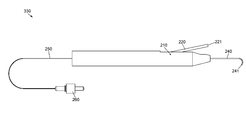
FIG. 2 is a schematic diagram illustrating an exploded view of a steerable laser probe assembly 200. In one or more embodiments, steerable laser probe assembly 200 may comprise a handle 100, a pivot pin 210, an actuation lever 220 having an actuation lever distal end 221 and an actuation lever proximal end 222, a flexible housing tube 240 having a flexible housing tube distal end 241 and a flexible housing tube proximal end 242, an optic fiber 250 having an optic fiber distal end 251 and an optic fiber proximal end 252, and a light source interface 260. Illustratively, light source interface 260 may be configured to interface with optic fiber 250, e.g., at optic fiber proximal end 252. In one or more embodiments, light source interface 260 may comprise a standard light source connecter, e.g., a SubMiniature version A (SMA) connector.
Illustratively, a portion of flexible housing tube 240 may be fixed to handle distal end 101, e.g., flexible housing tube proximal end 242 may be fixed to handle distal end 101. In one or more embodiments, a portion of flexible housing tube 240 may be fixed to handle distal end 101, e.g., by an adhesive or any suitable fixation means. Illustratively, a portion of flexible housing tube 240 may be disposed within optic fiber guide 160, e.g., flexible housing tube proximal end 242 may be disposed within optic fiber guide 160. In one or more embodiments, a portion of flexible housing tube 240 may be fixed within optic fiber guide 160, e.g., by an adhesive or any suitable fixation means. Flexible housing tube 240 may be manufactured from any suitable material, e.g., polymers, metals, metal alloys, etc., or from any combination of suitable materials. Illustratively, flexible housing tube 240 may comprise a shape memory material, e.g., Nitinol. In one or more embodiments, flexible housing tube 240 may be manufactured from a material having an ultimate tensile strength between 700 and 1000 MPa. Illustratively, flexible housing tube 240 may be manufactured from a material having ultimate tensile strength less than 700 MPa or greater than 1000 MPa. In one or more embodiments, flexible housing tube 240 may be manufactured from a material having a modulus of elasticity between 30 and 80 GPa. Illustratively, flexible housing tube 240 may be manufactured from a material having a modulus of elasticity less than 30 GPa or greater than 80 GPa. In one or more embodiments, flexible housing tube 240 may be manufactured with dimensions suitable for performing microsurgical procedures, e.g., ophthalmic surgical procedures. Illustratively, flexible housing tube 240 may have an ultimate tensile strength between 1000 MPa and 1100 MPa. In one or more embodiments, flexible housing tube 240 may have an ultimate tensile strength less than 1000 MPa or greater than 1100 MPa.
Illustratively, a portion of actuation lever 220 may be disposed within actuation lever guide 150, e.g., actuation lever proximal end 222 may be disposed within actuation lever guide 150. In one or more embodiments, actuation lever 220 may comprise a pivot pin chamber 225 configured to enclose a portion of pivot pin 210. Illustratively, pivot pin 210 may be disposed within both pivot pin housing 110 and pivot pin chamber 225. In one or more embodiments, pivot pin 210 may be fixed within pivot pin housing 110. Illustratively, pivot pin 210 may be fixed within pivot pin housing 110, e.g., by an adhesive or any suitable fixation means. In one or more embodiments, pivot pin 210 may be configured to fix a portion of actuation lever 220 to handle 100, e.g., at pivot pin chamber 225. Illustratively, when pivot pin 210 is disposed within pivot pin chamber 225, pivot pin 210 may be configured to limit an actuation of actuation lever 220, e.g., to allow rotational actuation of actuation lever 220 about pivot pin 210. In one or more embodiments, actuation lever 220 may be configured to rotate about pivot pin 210, e.g., in response to an application of a force to a portion of actuation lever 220. Illustratively, pivot pin chamber 225 may be coated with a material, e.g., Teflon, configured to facilitate a rotation of actuation lever 220 about pivot pin 210.
Illustratively, actuation lever 220 may comprise an optic fiber housing 230 configured to house a portion of optic fiber 250. In one or more embodiments, optic fiber 250 may be disposed within inner bore 140, actuation lever guide 150, optic fiber housing 230, optic fiber guide 160, and flexible housing tube 240. Illustratively, optic fiber 250 may be disposed within flexible housing tube 240 wherein optic fiber distal end 251 may be adjacent to flexible housing tube distal end 241. In one or more embodiments, a portion of optic fiber 250 may be fixed to an inner portion of flexible housing tube 240. Illustratively, a portion of optic fiber 250 may be fixed within flexible housing tube 240, e.g., by an adhesive or any suitable fixation means. In one or more embodiments, a portion of optic fiber 250 may be fixed within optic fiber housing 230, e.g., by an adhesive or any suitable fixation means. Illustratively, optic fiber 250 may be fixed within flexible housing tube 240 and optic fiber housing 230.
In one or more embodiments, a surgeon may actuate actuation lever 220, e.g., by applying a force to a portion of actuation lever 220. Illustratively, an application of a force to actuation lever 220 may be configured to actuate actuation lever distal end 221 about pivot pin 210, e.g., in a clockwise direction. In one or more embodiments, an actuation of actuation lever distal end 221 about pivot pin 210 in a clockwise direction may be configured to actuate actuation lever proximal end 222 about pivot pin 210, e.g., in a clockwise direction. Illustratively, an actuation of actuation lever proximal end 222 about pivot pin 210 in a clockwise direction may be configured to actuate optic fiber housing 230 within actuation lever guide 150, e.g., towards handle proximal end 102 and away from handle distal end 101. In one or more embodiments, an actuation of optic fiber housing 230 towards handle proximal end 102 and away from handle distal end 101 may be configured to retract optic fiber 250 relative to flexible housing tube 240. Illustratively, a retraction of optic fiber 250 relative to flexible housing tube 240 may be configured to apply a force, e.g., a compressive force, to a portion of flexible housing tube 240. In one or more embodiments, an application of a force to a portion of flexible housing tube 240 may be configured to compress a portion of flexible housing tube 240. Illustratively, a compression of a portion of flexible housing tube 240 may be configured to cause flexible housing tube 240 to gradually curve. In one or more embodiments, a gradual curving of flexible housing tube 240 may be configured to gradually curve optic fiber 250. Illustratively, an actuation of actuation lever distal end 221 about pivot pin 210 in a clockwise direction may be configured to gradually curve optic fiber 250, e.g. an application of a force to a portion of actuation lever 220 may be configured to gradually curve optic fiber 250.
In one or more embodiments, a surgeon may actuate actuation lever 220, e.g., by reducing a force applied to a portion of actuation lever 220. Illustratively, a reduction of a force applied to actuation lever 220 may be configured to actuate actuation lever distal end 221 about pivot pin 210, e.g., in a counter-clockwise direction. In one or more embodiments, an actuation of actuation lever distal end 221 about pivot pin 210 in a counter-clockwise direction may be configured to actuate actuation lever proximal end 222 about pivot pin 210, e.g., in a counter-clockwise direction. Illustratively, an actuation of actuation lever proximal end 222 about pivot pin 210 in a counter-clockwise direction may be configured to actuate optic fiber housing 230 within actuation lever guide 150, e.g., towards handle distal end 101 and away from handle proximal end 102. In one or more embodiments, an actuation of optic fiber housing 230 towards handle distal end 101 and away from handle proximal end 102 may be configured to extend optic fiber 250 relative to flexible housing tube 240. Illustratively, an extension of optic fiber 250 relative to flexible housing tube 240 may be configured to reduce a force, e.g., a compressive force, applied to a portion of flexible housing tube 240. In one or more embodiments, a reduction of a force applied to a portion of flexible housing tube 240 may be configured to decompress a portion of flexible housing tube 240. Illustratively, a decompression of a portion of flexible housing tube 240 may be configured to cause flexible housing tube 240 to gradually straighten. In one or more embodiments, a gradual straightening of flexible housing tube 240 may be configured to gradually straighten optic fiber 250. Illustratively, an actuation of actuation lever distal end 221 about pivot pin 210 in a counter-clockwise direction may be configured to gradually straighten optic fiber 250, e.g., a reduction of a force applied to portion of actuation lever 220 may be configured to gradually straighten optic fiber 250.
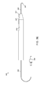
FIGS. 3A, 3B, 3C, 3D, and 3E illustrate a gradual curving of an optic fiber 250. FIG. 3A illustrates a straight optic fiber 300. In one or more embodiments, optic fiber 250 may comprise a straight optic fiber 300, e.g., when optic fiber 250 is fully extended relative to flexible housing tube 240. For example, optic fiber 250 may comprise a straight optic fiber 300 when optic fiber housing 230 is fully extended relative to flexible housing tube 240. Illustratively, optic fiber 250 may comprise a straight optic fiber 300, e.g., when a portion of flexible housing tube 240 is fully decompressed. In one or more embodiments, optic fiber 250 may comprise a straight optic fiber 300, e.g., when no force is applied to actuation lever 220. Illustratively, a line tangent to optic fiber distal end 251 may be parallel to a line tangent to flexible housing tube proximal end 242, e.g., when optic fiber 250 comprises a straight optic fiber 300.
FIG. 3B illustrates an optic fiber in a first curved position 310. In one or more embodiments, a rotation of actuation lever 220 about pivot pin 210 in a clockwise direction may be configured to gradually curve optic fiber 250 from a straight optic fiber 300 to an optic fiber in a first curved position 310. Illustratively, an application of a force to a portion of actuation lever 220 may be configured to rotate actuation lever distal end 221 about pivot pin 210 in a clockwise direction. In one or more embodiments, a rotation of actuation lever distal end 221 about pivot pin 210 in a clockwise direction may be configured to actuate optic fiber housing 230, e.g., towards handle proximal end 102 and away from handle distal end 101. Illustratively, an actuation of optic fiber housing 230 towards handle proximal end 102 and away from handle distal end 101 may be configured to retract optic fiber 250 relative to flexible housing tube 240. In one or more embodiments, a retraction of optic fiber 250 relative to flexible housing tube 240 may be configured to apply a compressive force to a portion of flexible housing tube 240. Illustratively, an application of a compressive force to a portion of flexible housing tube 240 may be configured to compress a portion of flexible housing tube 240 causing flexible housing tube 240 to gradually curve. In one or more embodiments, a gradual curving of flexible housing tube 240 may be configured to gradually curve optic fiber 250, e.g., from a straight optic fiber 300 to an optic fiber in a first curved position 310. Illustratively, a line tangent to optic fiber distal end 251 may intersect a line tangent to flexible housing tube proximal end 242 at a first angle, e.g., when optic fiber 250 comprises an optic fiber in a first curved position 310. In one or more embodiments, the first angle may comprise any angle greater than zero degrees. For example, the first angle may comprise a 45 degree angle.
FIG. 3C illustrates an optic fiber in a second curved position 320. In one or more embodiments, a rotation of actuation lever 220 about pivot pin 210 in a clockwise direction may be configured to gradually curve optic fiber 250 from an optic fiber in a first curved position 310 to an optic fiber in a second curved position 320. Illustratively, an application of a force to a portion of actuation lever 220 may be configured to rotate actuation lever distal end 221 about pivot pin 210 in a clockwise direction. In one or more embodiments, a rotation of actuation lever distal end 221 about pivot pin 210 in a clockwise direction may be configured to actuate optic fiber housing 230, e.g., towards handle proximal end 102 and away from handle distal end 101. Illustratively, an actuation of optic fiber housing 230 towards handle proximal end 102 and away from handle distal end 101 may be configured to retract optic fiber 250 relative to flexible housing tube 240. In one or more embodiments, a retraction of optic fiber 250 relative to flexible housing tube 240 may be configured to apply a compressive force to a portion of flexible housing tube 240. Illustratively, an application of a compressive force to a portion of flexible housing tube 240 may be configured to compress a portion of flexible housing tube 240 causing flexible housing tube 240 to gradually curve. In one or more embodiments, a gradual curving of flexible housing tube 240 may be configured to gradually curve optic fiber 250, e.g., from an optic fiber in a first curved position 310 to an optic fiber in a second curved position 320. Illustratively, a line tangent to optic fiber distal end 251 may intersect a line tangent to flexible housing tube proximal end 242 at a second angle, e.g., when optic fiber 250 comprises an optic fiber in a second curved position 320. In one or more embodiments, the second angle may comprise any angle greater than the first angle. For example, the second angle may comprise a 90 degree angle.
FIG. 3D illustrates an optic fiber in a third curved position 330. In one or more embodiments, a rotation of actuation lever 220 about pivot pin 210 in a clockwise direction may be configured to gradually curve optic fiber 250 from an optic fiber in a second curved position 320 to an optic fiber in a third curved position 330. Illustratively, an application of a force to a portion of actuation lever 220 may be configured to rotate actuation lever distal end 221 about pivot pin 210 in a clockwise direction. In one or more embodiments, a rotation of actuation lever distal end 221 about pivot pin 210 in a clockwise direction may be configured to actuate optic fiber housing 230, e.g., towards handle proximal end 102 and away from handle distal end 101. Illustratively, an actuation of optic fiber housing 230 towards handle proximal end 102 and away from handle distal end 101 may be configured to retract optic fiber 250 relative to flexible housing tube 240. In one or more embodiments, a retraction of optic fiber 250 relative to flexible housing tube 240 may be configured to apply a compressive force to a portion of flexible housing tube 240. Illustratively, an application of a compressive force to a portion of flexible housing tube 240 may be configured to compress a portion of flexible housing tube 240 causing flexible housing tube 240 to gradually curve. In one or more embodiments, a gradual curving of flexible housing tube 240 may be configured to gradually curve optic fiber 250, e.g., from an optic fiber in a second curved position 320 to an optic fiber in a third curved position 330. Illustratively, a line tangent to optic fiber distal end 251 may intersect a line tangent to flexible housing tube proximal end 242 at a third angle, e.g., when optic fiber 250 comprises an optic fiber in a third curved position 330. In one or more embodiments, the third angle may comprise any angle greater than the second angle. For example, the third angle may comprise a 135 degree angle.
FIG. 3E illustrates an optic fiber in a fourth curved position 340. In one or more embodiments, a rotation of actuation lever 220 about pivot pin 210 in a clockwise direction may be configured to gradually curve optic fiber 250 from an optic fiber in a third curved position 330 to an optic fiber in a fourth curved position 340. Illustratively, an application of a force to a portion of actuation lever 220 may be configured to rotate actuation lever distal end 221 about pivot pin 210 in a clockwise direction. In one or more embodiments, a rotation of actuation lever distal end 221 about pivot pin 210 in a clockwise direction may be configured to actuate optic fiber housing 230, e.g., towards handle proximal end 102 and away from handle distal end 101. Illustratively, an actuation of optic fiber housing 230 towards handle proximal end 102 and away from handle distal end 101 may be configured to retract optic fiber 250 relative to flexible housing tube 240. In one or more embodiments, a retraction of optic fiber 250 relative to flexible housing tube 240 may be configured to apply a compressive force to a portion of flexible housing tube 240. Illustratively, an application of a compressive force to a portion of flexible housing tube 240 may be configured to compress a portion of flexible housing tube 240 causing flexible housing tube 240 to gradually curve. In one or more embodiments, a gradual curving of flexible housing tube 240 may be configured to gradually curve optic fiber 250, e.g., from an optic fiber in a third curved position 330 to an optic fiber in a fourth curved position 340. Illustratively, a line tangent to optic fiber distal end 251 may be parallel to a line tangent to flexible housing tube proximal end 242, e.g., when optic fiber 250 comprises an optic fiber in a fourth curved position 340.
In one or more embodiments, one or more properties of a steerable laser probe may be adjusted to attain one or more desired steerable laser probe features. For example, a length that flexible housing tube distal end 241 extends from handle distal end 101 may be adjusted to vary a degree of rotation of actuation lever 220 configured to curve flexible housing tube 240 to a particular curved position. In one or more embodiments, a stiffness of flexible housing tube 240 may be adjusted to vary a degree of rotation of actuation lever 220 configured to curve flexible housing tube 240 to a particular curved position. Illustratively, a material comprising flexible housing tube 240 may be adjusted to vary a degree of rotation of actuation lever 220 configured to curve flexible housing tube 240 to a particular curved position.
Illustratively, a position of pivot pin 210 may be adjusted to vary a degree of rotation of actuation lever 220 configured to curve flexible housing tube 240 to a particular curved position. In one or more embodiments, a geometry of actuation lever 220 may be adjusted to vary a degree of rotation of actuation lever 220 configured to curve flexible housing tube 240 to a particular curved position. Illustratively, one or more locations within flexible housing tube 240 wherein optic fiber 250 may be fixed to an inner portion of flexible housing tube 240 may be adjusted to vary a degree of rotation of actuation lever 220 configured to curve flexible housing tube 240 to a particular curved position.
In one or more embodiments, a mechanism configured to control a gradual curving of optic fiber 250 or a gradual straightening of optic fiber 250 may be varied to, e.g., attain one or more desired steerable laser probe features. Illustratively, a mechanism configured to control a gradual curving of optic fiber 250 may or may not be configured to control a gradual straightening of optic fiber 250. In one or more embodiments, a mechanism configured to control a gradual straightening of optic fiber 250 may or may not be configured to control a gradual curving of optic fiber 250. Illustratively, a steerable laser probe may be modified to allow a surgeon to selectively fix optic fiber 250 in a particular curved position. In one or more embodiments, a detent or a pawl may be added to a steerable laser probe, e.g., to temporarily fix actuation lever 220 in a position relative to handle proximal end 102. Illustratively, one or more magnets may be added to a steerable laser probe, e.g., to temporarily fix actuation lever 220 in a position relative to handle proximal end 102. In one or more embodiments, a switch or any other suitable control mechanism may be added to a steerable laser probe to control a gradual curving of optic fiber 250 or a gradual straightening of optic fiber 250.
In one or more embodiments, at least a portion of optic fiber 250 may be enclosed in an optic fiber sleeve configured to, e.g., protect optic fiber 250, vary a stiffness of optic fiber 250, vary an optical property of optic fiber 250, etc. Illustratively, an optic fiber sleeve may be configured to compress a portion of flexible housing tube 240. For example, an optic fiber sleeve may enclose a portion of optic fiber 250 and the optic fiber sleeve may be fixed within optic fiber housing 230 and also fixed to a portion of flexible housing tube 240. In one or more embodiments, a rotation of actuation lever 220 about pivot pin 210 in a clockwise direction may be configured to retract an optic fiber sleeve relative to flexible housing tube 240. Illustratively, a retraction of an optic fiber sleeve relative to flexible housing tube 240 may be configured to cause the optic fiber sleeve to apply a force, e.g., a compressive force, to a portion of flexible housing tube 240. In one or more embodiments, an application of a force to a portion of flexible housing tube 240 may be configured to compress a portion of flexible housing tube 240 causing flexible housing tube 240 to gradually curve.
FIGS. 4A, 4B, 4C, 4D, and 4E illustrate a gradual straightening of an optic fiber 250. FIG. 4A illustrates a fully curved optic fiber 400. In one or more embodiments, optic fiber 250 may comprise a fully curved optic fiber 400, e.g., when optic fiber 250 is fully retracted relative to flexible housing tube 240. For example, optic fiber 250 may comprise a fully curved optic fiber 400 when optic fiber housing 230 is fully retracted relative to flexible housing tube 240. Illustratively, optic fiber 250 may comprise a fully curved optic fiber 400, e.g., when a portion of flexible housing tube 240 is compressed. In one or more embodiments, optic fiber 250 may comprise a fully curved optic fiber 400, e.g., when a force is applied to actuation lever 220. Illustratively, a line tangent to optic fiber distal end 251 may be parallel to a line tangent to flexible housing tube proximal end 242, e.g., when optic fiber 250 comprises a fully curved optic fiber 400.
FIG. 4B illustrates an optic fiber in a first partially straightened position 410. In one or more embodiments, a rotation of actuation lever 220 about pivot pin 210 in a counter-clockwise direction may be configured to gradually straighten optic fiber 250 from a fully curved optic fiber 400 to an optic fiber in a first partially straightened position 410. Illustratively, a reduction of a force applied to a portion of actuation lever 220 may be configured to rotate actuation lever distal end 221 about pivot pin 210 in a counter-clockwise direction. In one or more embodiments, a rotation of actuation lever distal end 221 about pivot pin 210 in a counter-clockwise direction may be configured to actuate optic fiber housing 230, e.g., towards handle distal end 101 and away from handle proximal end 102. Illustratively, an actuation of optic fiber housing 230 towards handle distal end 101 and away from handle proximal end 102 may be configured to extend optic fiber 250 relative to flexible housing tube 240. In one or more embodiments, an extension of optic fiber 250 relative to flexible housing tube 240 may be configured to reduce a compressive force applied to a portion of flexible housing tube 240. Illustratively, a reduction of a compressive force applied to a portion of flexible housing tube 240 may be configured to decompress a portion of flexible housing tube 240 causing flexible housing tube 240 to gradually straighten. In one or more embodiments, a gradual straightening of flexible housing tube 240 may be configured to gradually straighten optic fiber 250, e.g., from a fully curved optic fiber 400 to an optic fiber in a first partially straightened position 410. Illustratively, a line tangent to optic fiber distal end 251 may intersect a line tangent to flexible housing tube proximal end 242 at a first partially straightened angle, e.g., when optic fiber 250 comprises an optic fiber in a first partially straightened position 410. In one or more embodiments, the first partially straightened angle may comprise any angle less than 180 degrees. For example, the first partially straightened angle may comprise a 135 degree angle.
FIG. 4C illustrates an optic fiber in a second partially straightened position 420. In one or more embodiments, a rotation of actuation lever 220 about pivot pin 210 in a counter-clockwise direction may be configured to gradually straighten optic fiber 250 from an optic fiber in a first partially straightened position 410 to an optic fiber in a second partially straightened position 420. Illustratively, a reduction of a force applied to a portion of actuation lever 220 may be configured to rotate actuation lever distal end 221 about pivot pin 210 in a counter-clockwise direction. In one or more embodiments, a rotation of actuation lever distal end 221 about pivot pin 210 in a counter-clockwise direction may be configured to actuate optic fiber housing 230, e.g., towards handle distal end 101 and away from handle proximal end 102. Illustratively, an actuation of optic fiber housing 230 towards handle distal end 101 and away from handle proximal end 102 may be configured to extend optic fiber 250 relative to flexible housing tube 240. In one or more embodiments, an extension of optic fiber 250 relative to flexible housing tube 240 may be configured to reduce a compressive force applied to a portion of flexible housing tube 240. Illustratively, a reduction of a compressive force applied to a portion of flexible housing tube 240 may be configured to decompress a portion of flexible housing tube 240 causing flexible housing tube 240 to gradually straighten. In one or more embodiments, a gradual straightening of flexible housing tube 240 may be configured to gradually straighten optic fiber 250, e.g., from an optic fiber in a first partially straightened position 410 to an optic fiber in a second partially straightened position 420. Illustratively, a line tangent to optic fiber distal end 251 may intersect a line tangent to flexible housing tube proximal end 242 at a second partially straightened angle, e.g., when optic fiber 250 comprises an optic fiber in a second partially straightened position 420. In one or more embodiments, the second partially straightened angle may comprise any angle less than the first partially straightened angle. For example, the second partially straightened angle may comprise a 90 degree angle.
FIG. 4D illustrates an optic fiber in a third partially straightened position 430. In one or more embodiments, a rotation of actuation lever 220 about pivot pin 210 in a counter-clockwise direction may be configured to gradually straighten optic fiber 250 from an optic fiber in a second partially straightened position 420 to an optic fiber in a third partially straightened position 430. Illustratively, a reduction of a force applied to a portion of actuation lever 220 may be configured to rotate actuation lever distal end 221 about pivot pin 210 in a counter-clockwise direction. In one or more embodiments, a rotation of actuation lever distal end 221 about pivot pin 210 in a counter-clockwise direction may be configured to actuate optic fiber housing 230, e.g., towards handle distal end 101 and away from handle proximal end 102. Illustratively, an actuation of optic fiber housing 230 towards handle distal end 101 and away from handle proximal end 102 may be configured to extend optic fiber 250 relative to flexible housing tube 240. In one or more embodiments, an extension of optic fiber 250 relative to flexible housing tube 240 may be configured to reduce a compressive force applied to a portion of flexible housing tube 240. Illustratively, a reduction of a compressive force applied to a portion of flexible housing tube 240 may be configured to decompress a portion of flexible housing tube 240 causing flexible housing tube 240 to gradually straighten. In one or more embodiments, a gradual straightening of flexible housing tube 240 may be configured to gradually straighten optic fiber 250, e.g., from an optic fiber in a second partially straightened position 420 to an optic fiber in a third partially straightened position 430. Illustratively, a line tangent to optic fiber distal end 251 may intersect a line tangent to flexible housing tube proximal end 242 at a third partially straightened angle, e.g., when optic fiber 250 comprises an optic fiber in a third partially straightened position 430. In one or more embodiments, the third partially straightened angle may comprise any angle less than the second partially straightened angle. For example, the third partially straightened angle may comprise a 45 degree angle.
FIG. 4E illustrates an optic fiber in a fully straightened position 440. In one or more embodiments, a rotation of actuation lever 220 about pivot pin 210 in a counter-clockwise direction may be configured to gradually straighten optic fiber 250 from an optic fiber in a third partially straightened position 430 to an optic fiber in a fully straightened position 440. Illustratively, a reduction of a force applied to a portion of actuation lever 220 may be configured to rotate actuation lever distal end 221 about pivot pin 210 in a counter-clockwise direction. In one or more embodiments, a rotation of actuation lever distal end 221 about pivot pin 210 in a counter-clockwise direction may be configured to actuate optic fiber housing 230, e.g., towards handle distal end 101 and away from handle proximal end 102. Illustratively, an actuation of optic fiber housing 230 towards handle distal end 101 and away from handle proximal end 102 may be configured to extend optic fiber 250 relative to flexible housing tube 240. In one or more embodiments, an extension of optic fiber 250 relative to flexible housing tube 240 may be configured to reduce a compressive force applied to a portion of flexible housing tube 240. Illustratively, a reduction of a compressive force applied to a portion of flexible housing tube 240 may be configured to decompress a portion of flexible housing tube 240 causing flexible housing tube 240 to gradually straighten. In one or more embodiments, a gradual straightening of flexible housing tube 240 may be configured to gradually straighten optic fiber 250, e.g., from an optic fiber in a third partially straightened position 430 to an optic fiber in a fully straightened position 440. Illustratively, a line tangent to optic fiber distal end 251 may be parallel to a line tangent to flexible housing tube proximal end 242, e.g., when optic fiber 250 comprises an optic fiber in a fully straightened position 440.
Illustratively, a surgeon may aim optic fiber distal end 251 at any of a plurality of targets within an eye, e.g., to perform a photocoagulation procedure. In one or more embodiments, a surgeon may aim optic fiber distal end 251 at any target within a particular transverse plane of the inner eye by, e.g., rotating handle 100 to orient flexible housing tube 240 in an orientation configured to cause a curvature of flexible housing tube 240 within the particular transverse plane of the inner eye and varying a degree of rotation of actuation lever 220 about pivot pin 210. Illustratively, a surgeon may aim optic fiber distal end 251 at any target within a particular sagittal plane of the inner eye by, e.g., rotating handle 100 to orient flexible housing tube 240 in an orientation configured to cause a curvature of flexible housing tube 240 within the particular sagittal plane of the inner eye and varying a degree of rotation of actuation lever 220 about pivot pin 210. In one or more embodiments, a surgeon may aim optic fiber distal end 251 at any target within a particular frontal plane of the inner eye by, e.g., varying a degree of rotation of actuation lever 220 about pivot pin 210 to orient a line tangent to optic fiber distal end 251 wherein the line tangent to optic fiber distal end 251 is within the particular frontal plane of the inner eye and rotating handle 100. Illustratively, a surgeon may aim optic fiber distal end 251 at any target located outside of the particular transverse plane, the particular sagittal plane, and the particular frontal plane of the inner eye, e.g., by varying a rotational orientation of handle 100 and varying a degree of rotation of actuation lever 220 about pivot pin 210. In one or more embodiments, a surgeon may aim optic fiber distal end 251 at any target of a plurality of targets within an eye, e.g., without increasing a length of a portion of a steerable laser probe within the eye. Illustratively, a surgeon may aim optic fiber distal end 251 at any target of a plurality of targets within an eye, e.g., without decreasing a length of a portion of a steerable laser probe within the eye.
FIG. 5 is a schematic diagram illustrating an exploded view of a steerable laser probe assembly 500. In one or more embodiments, steerable laser probe assembly 500 may comprise a handle 100, a pivot pin 510, an actuation lever 520 having an actuation lever distal end 521 and an actuation lever proximal end 522, a cable 540 having a cable distal end 541 and a cable proximal end 542, a flexible housing tube 240 having a flexible housing tube distal end 241 and a flexible housing tube proximal end 242, an optic fiber 250 having an optic fiber distal end 251 and an optic fiber proximal end 252, and a light source interface 260. Illustratively, light source interface 260 may be configured to interface with optic fiber 250, e.g., at optic fiber proximal end 252. In one or more embodiments, light source interface 260 may comprise a standard light source connecter, e.g., an SMA connector.
Illustratively, a portion of flexible housing tube 240 may be fixed to handle distal end 101, e.g., flexible housing tube proximal end 242 may be fixed to handle distal end 101. In one or more embodiments, a portion of flexible housing tube 240 may be fixed to handle distal end 101, e.g., by an adhesive or any suitable fixation means. Illustratively, a portion of flexible housing tube 240 may be disposed within optic fiber guide 160, e.g., flexible housing tube proximal end 242 may be disposed within optic fiber guide 160. In one or more embodiments, a portion of flexible housing tube 240 may be fixed within optic fiber guide 160, e.g., by an adhesive or any suitable fixation means. Flexible housing tube 240 may be manufactured from any suitable material, e.g., polymers, metals, metal alloys, etc., or from any combination of suitable materials. Illustratively, flexible housing tube 240 may comprise a shape memory material, e.g., Nitinol. In one or more embodiments, flexible housing tube 240 may be manufactured from a material having an ultimate tensile strength between 700 and 1000 MPa. Illustratively, flexible housing tube 240 may be manufactured from a material having ultimate tensile strength less than 700 MPa or greater than 1000 MPa. In one or more embodiments, flexible housing tube 240 may be manufactured from a material having a modulus of elasticity between 30 and 80 GPa. Illustratively, flexible housing tube 240 may be manufactured from a material having a modulus of elasticity less than 30 GPa or greater than 80 GPa. In one or more embodiments, flexible housing tube 240 may be manufactured with dimensions suitable for performing microsurgical procedures, e.g., ophthalmic surgical procedures. Illustratively, flexible housing tube 240 may have an ultimate tensile strength between 1000 MPa and 1100 MPa. In one or more embodiments, flexible housing tube 240 may have an ultimate tensile strength less than 1000 MPa or greater than 1100 MPa.
Illustratively, a portion of actuation lever 520 may be disposed within actuation lever guide 150, e.g., actuation lever proximal end 522 may be disposed within actuation lever guide 150. In one or more embodiments, actuation lever 520 may comprise a pivot pin chamber 525 configured to enclose a portion of pivot pin 510. Illustratively, pivot pin 510 may be disposed within both pivot pin housing 110 and pivot pin chamber 525. In one or more embodiments, pivot pin 510 may be fixed within pivot pin housing 110. Illustratively, pivot pin 510 may be fixed within pivot pin housing 110, e.g., by an adhesive or any suitable fixation means. In one or more embodiments, pivot pin 510 may be configured to fix a portion of actuation lever 520 to handle 100, e.g., at pivot pin chamber 525. Illustratively, when pivot pin 510 is disposed within pivot pin chamber 525, pivot pin 510 may be configured to limit an actuation of actuation lever 520, e.g., to allow rotational actuation of actuation lever 520 about pivot pin 510. In one or more embodiments, actuation lever 520 may be configured to rotate about pivot pin 510, e.g., in response to an application of a force to a portion of actuation lever 520. Illustratively, pivot pin chamber 525 may be coated with a material, e.g., Teflon, configured to facilitate a rotation of actuation lever 520 about pivot pin 510.
In one or more embodiments, optic fiber 250 may be disposed within inner bore 140, actuation lever guide 150, optic fiber guide 160, and flexible housing tube 240. Illustratively, optic fiber 250 may be disposed within flexible housing tube 240 wherein optic fiber distal end 251 may be adjacent to flexible housing tube distal end 241. In one or more embodiments, a portion of optic fiber 250 may be fixed to an inner portion of flexible housing tube 240. Illustratively, a portion of optic fiber 250 may be fixed within flexible housing tube 240, e.g., by an adhesive or any suitable fixation means.
Illustratively, actuation lever 520 may comprise a cable housing 530 configured to house a portion of cable 540, e.g., cable proximal end 542. In one or more embodiments, cable 540 may be disposed within cable housing 530, actuation lever guide 150, optic fiber guide 160, and flexible housing tube 240. Illustratively, cable 540 may be disposed within flexible housing tube 240 wherein cable distal end 541 may be adjacent to flexible housing tube distal end 241. In one or more embodiments, a portion of cable 540 may be fixed to an inner portion of flexible housing tube 240. Illustratively, a portion of cable 540 may be fixed within flexible housing tube 240, e.g., by an adhesive or any suitable fixation means. In one or more embodiments, a portion of cable 540 may be fixed within cable housing 530, e.g., cable proximal end 542 may be disposed within cable housing 530. Illustratively, a portion of cable 540 may be fixed within cable housing 530, e.g., by an adhesive or any suitable fixation mechanism. In one or more embodiments, a portion of cable 540 may be fixed to an inner portion of flexible tube 240 and a portion of cable 540 may be fixed within cable housing 530.
In one or more embodiments, a surgeon may actuate actuation lever 520, e.g., by applying a force to a portion of actuation lever 520. Illustratively, an application of a force to actuation lever 520 may be configured to actuate actuation lever distal end 521 about pivot pin 510, e.g., in a clockwise direction. In one or more embodiments, an actuation of actuation lever distal end 521 about pivot pin 510 in a clockwise direction may be configured to actuate actuation lever proximal end 522 about pivot pin 510, e.g., in a clockwise direction. Illustratively, an actuation of actuation lever proximal end 522 about pivot pin 510 in a clockwise direction may be configured to actuate cable housing 530 within actuation lever guide 150, e.g., towards handle proximal end 102 and away from handle distal end 101. In one or more embodiments, an actuation of cable housing 530 towards handle proximal end 102 and away from handle distal end 101 may be configured to retract cable 540 relative to flexible housing tube 240. Illustratively, a retraction of cable 540 relative to flexible housing tube 240 may be configured to apply a force, e.g., a compressive force, to a portion of flexible housing tube 240. In one or more embodiments, an application of a force to a portion of flexible housing tube 240 may be configured to compress a portion of flexible housing tube 240. Illustratively, a compression of a portion of flexible housing tube 240 may be configured to cause flexible housing tube 240 to gradually curve. In one or more embodiments, a gradual curving of flexible housing tube 240 may be configured to gradually curve optic fiber 250. Illustratively, an actuation of actuation lever distal end 521 about pivot pin 510 in a clockwise direction may be configured to gradually curve optic fiber 250, e.g., an application of a force to a portion of actuation lever 520 may be configured to gradually curve optic fiber 250.
In one or more embodiments, a surgeon may actuate actuation lever 520, e.g., by reducing a force applied to a portion of actuation lever 520. Illustratively, a reduction of a force applied to actuation lever 520 may be configured to actuate actuation lever distal end 521 about pivot pin 510, e.g., in a counter-clockwise direction. In one or more embodiments, an actuation of actuation lever distal end 521 about pivot pin 510 in a counter-clockwise direction may be configured to actuate actuation lever proximal end 522 about pivot pin 510, e.g., in a counter-clockwise direction. Illustratively, an actuation of actuation lever proximal end 522 about pivot pin 510 in a counter-clockwise direction may be configured to actuate cable housing 530 within actuation lever guide 150, e.g., towards handle distal end 101 and away from handle proximal end 102. In one or more embodiments, an actuation of cable housing 530 towards handle distal end 101 and away from handle proximal end 102 may be configured to extend cable 540 relative to flexible housing tube 240. Illustratively, an extension of cable 540 relative to flexible housing tube 240 may be configured to reduce a force, e.g., a compressive force, applied to a portion of flexible housing tube 240. In one or more embodiments, a reduction of a force applied to a portion of flexible housing tube 240 may be configured to decompress a portion of flexible housing tube 240. Illustratively, a decompression of a portion of flexible housing tube 240 may be configured to cause flexible housing tube 240 to gradually straighten. In one or more embodiments, a gradual straightening of flexible housing tube 240 may be configured to gradually straighten optic fiber 250. Illustratively, an actuation of actuation lever distal end 521 about pivot pin 510 in a counter-clockwise direction may be configured to gradually straighten optic fiber 250, e.g., a reduction of a force applied to a portion of actuation lever 520 may be configured to gradually straighten optic fiber 250.
FIGS. 6A, 6B, 6C, 6D, and 6E illustrate a gradual curving of an optic fiber 250. FIG. 6A illustrates a straight optic fiber 600. In one or more embodiments, optic fiber 250 may comprise a straight optic fiber 600, e.g., when cable 540 is fully extended relative to flexible housing tube 240. For example, optic fiber 250 may comprise a straight optic fiber 600 when cable housing 530 is fully extended relative to flexible housing tube 240. Illustratively, optic fiber 250 may comprise a straight optic fiber 600, e.g., when a portion of flexible housing tube 240 is fully decompressed. In one or more embodiments, optic fiber 250 may comprise a straight optic fiber 600, e.g., when no force is applied to actuation lever 520. Illustratively, a line tangent to optic fiber distal end 251 may be parallel to a line tangent to flexible housing tube proximal end 242, e.g., when optic fiber 250 comprises a straight optic fiber 600.
FIG. 6B illustrates an optic fiber in a first curved position 610. In one or more embodiments, a rotation of actuation lever 520 about pivot pin 510 in a clockwise direction may be configured to gradually curve optic fiber 250 from a straight optic fiber 600 to an optic fiber in a first curved position 610. Illustratively, an application of a force to a portion of actuation lever 520 may be configured to rotate actuation lever distal end 521 about pivot pin 510 in a clockwise direction. In one or more embodiments, a rotation of actuation lever distal end 521 about pivot pin 510 in a clockwise direction may be configured to actuate cable housing 530, e.g., towards handle proximal end 102 and away from handle distal end 101. Illustratively, an actuation of cable housing 530 towards handle proximal end 102 and away from handle distal end 101 may be configured to retract cable 540 relative to flexible housing tube 240. In one or more embodiments, a retraction of cable 540 relative to flexible housing tube 240 may be configured to apply a compressive force to a portion of flexible housing tube 240. Illustratively, an application of a compressive force to a portion of flexible housing tube 240 may be configured to compress a portion of flexible housing tube 240 causing flexible housing tube 240 to gradually curve. In one or more embodiments, a gradual curving of flexible housing tube 240 may be configured to gradually curve optic fiber 250, e.g., from a straight optic fiber 600 to an optic fiber in a first curved position 610. Illustratively, a line tangent to optic fiber distal end 251 may intersect a line tangent to flexible housing tube proximal end 242 at a first angle, e.g., when optic fiber 250 comprises an optic fiber in a first curved position 610. In one or more embodiments, the first angle may comprise any angle greater than zero degrees. For example, the first angle may comprise a 45 degree angle.
FIG. 6C illustrates an optic fiber in a second curved position 620. In one or more embodiments, a rotation of actuation lever 520 about pivot pin 510 in a clockwise direction may be configured to gradually curve optic fiber 250 from an optic fiber in a first curved position 610 to an optic fiber in a second curved position 620. Illustratively, an application of a force to a portion of actuation lever 520 may be configured to rotate actuation lever distal end 521 about pivot pin 510 in a clockwise direction. In one or more embodiments, a rotation of actuation lever distal end 521 about pivot pin 510 in a clockwise direction may be configured to actuate cable housing 530, e.g., towards handle proximal end 102 and away from handle distal end 101. Illustratively, an actuation of cable housing 530 towards handle proximal end 102 and away from handle distal end 101 may be configured to retract cable 540 relative to flexible housing tube 240. In one or more embodiments, a retraction of cable 540 relative to flexible housing tube 240 may be configured to apply a compressive force to a portion of flexible housing tube 240. Illustratively, an application of a compressive force to a portion of flexible housing tube 240 may be configured to compress a portion of flexible housing tube 240 causing flexible housing tube 240 to gradually curve. In one or more embodiments, a gradual curving of flexible housing tube 240 may be configured to gradually curve optic fiber 250, e.g., from an optic fiber in a first curved position 610 to an optic fiber in a second curved position 620. Illustratively, a line tangent to optic fiber distal end 251 may intersect a line tangent to flexible housing tube proximal end 242 at a second angle, e.g., when optic fiber 250 comprises an optic fiber in a second curved position 620. In one or more embodiments, the second angle may comprise any angle greater than the first angle. For example, the second angle may comprise a 90 degree angle.
FIG. 6D illustrates an optic fiber in a third curved position 630. In one or more embodiments, a rotation of actuation lever 520 about pivot pin 510 in a clockwise direction may be configured to gradually curve optic fiber 250 from an optic fiber in a second curved position 620 to an optic fiber in a third curved position 630. Illustratively, an application of a force to a portion of actuation lever 520 may be configured to rotate actuation lever distal end 521 about pivot pin 510 in a clockwise direction. In one or more embodiments, a rotation of actuation lever distal end 521 about pivot pin 510 in a clockwise direction may be configured to actuate cable housing 530, e.g., towards handle proximal end 102 and away from handle distal end 101. Illustratively, an actuation of cable housing 530 towards handle proximal end 102 and away from handle distal end 101 may be configured to retract cable 540 relative to flexible housing tube 240. In one or more embodiments, a retraction of cable 540 relative to flexible housing tube 240 may be configured to apply a compressive force to a portion of flexible housing tube 240. Illustratively, an application of a compressive force to a portion of flexible housing tube 240 may be configured to compress a portion of flexible housing tube 240 causing flexible housing tube 240 to gradually curve. In one or more embodiments, a gradual curving of flexible housing tube 240 may be configured to gradually curve optic fiber 250, e.g., from an optic fiber in a second curved position 620 to an optic fiber in a third curved position 630. Illustratively, a line tangent to optic fiber distal end 251 may intersect a line tangent to flexible housing tube proximal end 242 at a third angle, e.g., when optic fiber 250 comprises an optic fiber in a third curved position 630. In one or more embodiments, the third angle may comprise any angle greater than the second angle. For example, the third angle may comprise a 135 degree angle.
FIG. 6E illustrates an optic fiber in a fourth curved position 640. In one or more embodiments, a rotation of actuation lever 520 about pivot pin 510 in a clockwise direction may be configured to gradually curve optic fiber 250 from an optic fiber in a third curved position 630 to an optic fiber in a fourth curved position 640. Illustratively, an application of a force to a portion of actuation lever 520 may be configured to rotate actuation lever distal end 521 about pivot pin 510 in a clockwise direction. In one or more embodiments, a rotation of actuation lever distal end 521 about pivot pin 510 in a clockwise direction may be configured to actuate cable housing 530, e.g., towards handle proximal end 102 and away from handle distal end 101. Illustratively, an actuation of cable housing 530 towards handle proximal end 102 and away from handle distal end 101 may be configured to retract cable 540 relative to flexible housing tube 240. In one or more embodiments, a retraction of cable 540 relative to flexible housing tube 240 may be configured to apply a compressive force to a portion of flexible housing tube 240. Illustratively, an application of a compressive force to a portion of flexible housing tube 240 may be configured to compress a portion of flexible housing tube 240 causing flexible housing tube 240 to gradually curve. In one or more embodiments, a gradual curving of flexible housing tube 240 may be configured to gradually curve optic fiber 250, e.g., from an optic fiber in a third curved position 630 to an optic fiber in a fourth curved position 640. Illustratively, a line tangent to optic fiber distal end 251 may be parallel to a line tangent to flexible housing tube proximal end 242, e.g., when optic fiber 250 comprises an optic fiber in a fourth curved position 640.
In one or more embodiments, one or more properties of a steerable laser probe may be adjusted to attain one or more desired steerable laser probe features. For example, a length that flexible housing tube distal end 241 extends from handle distal end 101 may be adjusted to vary a degree of rotation of actuation lever 520 configured to curve flexible housing tube 240 to a particular curved position. In one or more embodiments, a stiffness of flexible housing tube 240 may be adjusted to vary a degree of rotation of actuation lever 520 configured to curve flexible housing tube 240 to a particular curved position. Illustratively, a material comprising flexible housing tube 240 may be adjusted to vary a degree of rotation of actuation lever 520 configured to curve flexible housing tube 240 to a particular curved position.
Illustratively, a position of pivot pin 510 may be adjusted to vary a degree of rotation of actuation lever 520 configured to curve flexible housing tube 240 to a particular curved position. In one or more embodiments, a geometry of actuation lever 520 may be adjusted to vary a degree of rotation of actuation lever 520 configured to curve flexible housing tube 240 to a particular curved position. Illustratively, one or more locations within flexible housing tube 240 wherein cable 540 may be fixed to an inner portion of flexible housing tube 240 may be adjusted to vary a degree of rotation of actuation lever 520 configured to curve flexible housing tube 240 to a particular curved position.
In one or more embodiments, a mechanism configured to control a gradual curving of optic fiber 250 or a gradual straightening of optic fiber 250 may be varied to, e.g., attain one or more desired steerable laser probe features. Illustratively, a mechanism configured to control a gradual curving of optic fiber 250 may or may not be configured to control a gradual straightening of optic fiber 250. In one or more embodiments, a mechanism configured to control a gradual straightening of optic fiber 250 may or may not be configured to control a gradual curving of optic fiber 250. Illustratively, a steerable laser probe may be modified to allow a surgeon to selectively fix optic fiber 250 in a particular curved position. In one or more embodiments, a detent or a pawl may be added to a steerable laser probe, e.g., to temporarily fix actuation lever 520 in a position relative to handle proximal end 102. Illustratively, one or more magnets may be added to a steerable laser probe, e.g., to temporarily fix actuation lever 520 in a position relative to handle proximal end 102. In one or more embodiments, a switch or any other suitable control mechanism may be added to a steerable laser probe to control a gradual curving of optic fiber 250 or a gradual straightening of optic fiber 250.
In one or more embodiments, at least a portion of optic fiber 250 may be enclosed in an optic fiber sleeve configured to, e.g., protect optic fiber 250, vary a stiffness of optic fiber 250, vary an optical property of optic fiber 250, etc. Illustratively, an optic fiber sleeve may be configured to compress a first portion of flexible housing tube 240 and cable 540 may be configured to compress a second portion of flexible housing tube 240. For example, an optic fiber sleeve may enclose a portion of optic fiber 250 and the optic fiber sleeve may be fixed within cable housing 530 and also fixed to a portion of flexible housing tube 240. In one or more embodiments, a rotation of actuation lever 520 about pivot pin 510 in a clockwise direction may be configured to retract an optic fiber sleeve relative to flexible housing tube 240. Illustratively, a retraction of an optic fiber sleeve relative to flexible housing tube 240 may be configured to cause the optic fiber sleeve to apply a force, e.g., a compressive force, to a portion of flexible housing tube 240. In one or more embodiments, an application of a force to a portion of flexible housing tube 240 may be configured to compress a portion of flexible housing tube 240 causing flexible housing tube 240 to gradually curve.
FIGS. 7A, 7B, 7C, 7D, and 7E illustrate a gradual straightening of an optic fiber 250. FIG. 7A illustrates a fully curved optic fiber 700. In one or more embodiments, optic fiber 250 may comprise a fully curved optic fiber 700, e.g., when cable 540 is fully refracted relative to flexible housing tube 240. For example, optic fiber 250 may comprise a fully curved optic fiber 700 when cable housing 530 is fully retracted relative to flexible housing tube 240. Illustratively, optic fiber 250 may comprise a fully curved optic fiber 700, e.g., when a portion of flexible housing tube 240 is compressed. In one or more embodiments, optic fiber 250 may comprise a fully curved optic fiber 700, e.g., when a force is applied to actuation lever 520. Illustratively, a line tangent to optic fiber distal end 251 may be parallel to a line tangent to flexible housing tube proximal end 242, e.g., when optic fiber 250 comprises a fully curved optic fiber 700.
FIG. 7B illustrates an optic fiber in a first partially straightened position 710. In one or more embodiments, a rotation of actuation lever 520 about pivot pin 510 in a counter-clockwise direction may be configured to gradually straighten optic fiber 250 from a fully curved optic fiber 700 to an optic fiber in a first partially straightened position 710. Illustratively, a reduction of a force applied to a portion of actuation lever 520 may be configured to rotate actuation lever distal end 521 about pivot pin 510 in a counter-clockwise direction. In one or more embodiments, a rotation of actuation lever distal end 521 about pivot pin 510 in a counter-clockwise direction may be configured to actuate cable housing 530, e.g., towards handle distal end 101 and away from handle proximal end 102. Illustratively, an actuation of cable housing 530 towards handle distal end 101 and away from handle proximal end 102 may be configured to extend cable 540 relative to flexible housing tube 240. In one or more embodiments, an extension of cable 540 relative to flexible housing tube 240 may be configured to reduce a compressive force applied to a portion of flexible housing tube 240. Illustratively, a reduction of a compressive force applied to a portion of flexible housing tube 240 may be configured to decompress a portion of flexible housing tube 240 causing flexible housing tube 240 to gradually straighten. In one or more embodiments, a gradual straightening of flexible housing tube 240 may be configured to gradually straighten optic fiber 250, e.g., from a fully curved optic fiber 700 to an optic fiber in a first partially straightened position 710. Illustratively, a line tangent to optic fiber distal end 251 may intersect a line tangent to flexible housing tube proximal end 242 at a first partially straightened angle, e.g., when optic fiber 250 comprises an optic fiber in a first partially straightened position 710. In one or more embodiments, the first partially straightened angle may comprise any angle less than 180 degrees. For example, the first partially straightened angle may comprise a 135 degree angle.
FIG. 7C illustrates an optic fiber in a second partially straightened position 720. In one or more embodiments, a rotation of actuation lever 520 about pivot pin 510 in a counter-clockwise direction may be configured to gradually straighten optic fiber 250 from an optic fiber in a first partially straightened position 710 to an optic fiber in a second partially straightened position 720. Illustratively, a reduction of a force applied to a portion of actuation lever 520 may be configured to rotate actuation lever distal end 521 about pivot pin 510 in a counter-clockwise direction. In one or more embodiments, a rotation of actuation lever distal end 521 about pivot pin 510 in a counter-clockwise direction may be configured to actuate cable housing 530, e.g., towards handle distal end 101 and away from handle proximal end 102. Illustratively, an actuation of cable housing 530 towards handle distal end 101 and away from handle proximal end 102 may be configured to extend cable 540 relative to flexible housing tube 240. In one or more embodiments, an extension of cable 540 relative to flexible housing tube 240 may be configured to reduce a compressive force applied to a portion of flexible housing tube 240. Illustratively, a reduction of a compressive force applied to a portion of flexible housing tube 240 may be configured to decompress a portion of flexible housing tube 240 causing flexible housing tube 240 to gradually straighten. In one or more embodiments, a gradual straightening of flexible housing tube 240 may be configured to gradually straighten optic fiber 250, e.g., from an optic fiber in a first partially straightened position 710 to an optic fiber in a second partially straightened position 720. Illustratively, a line tangent to optic fiber distal end 251 may intersect a line tangent to flexible housing tube proximal end 242 at a second partially straightened angle, e.g., when optic fiber 250 comprises an optic fiber in a second partially straightened position 720. In one or more embodiments, the second partially straightened angle may comprise any angle less than the first partially straightened angle. For example, the second partially straightened angle may comprise a 90 degree angle.
FIG. 7D illustrates an optic fiber in a third partially straightened position 730. In one or more embodiments, a rotation of actuation lever 520 about pivot pin 510 in a counter-clockwise direction may be configured to gradually straighten optic fiber 250 from an optic fiber in a second partially straightened position 720 to an optic fiber in a third partially straightened position 730. Illustratively, a reduction of a force applied to a portion of actuation lever 520 may be configured to rotate actuation lever distal end 521 about pivot pin 510 in a counter-clockwise direction. In one or more embodiments, a rotation of actuation lever distal end 521 about pivot pin 510 in a counter-clockwise direction may be configured to actuate cable housing 530, e.g., towards handle distal end 101 and away from handle proximal end 102. Illustratively, an actuation of cable housing 530 towards handle distal end 101 and away from handle proximal end 102 may be configured to extend cable 540 relative to flexible housing tube 240. In one or more embodiments, an extension of cable 540 relative to flexible housing tube 240 may be configured to reduce a compressive force applied to a portion of flexible housing tube 240. Illustratively, a reduction of a compressive force applied to a portion of flexible housing tube 240 may be configured to decompress a portion of flexible housing tube 240 causing flexible housing tube 240 to gradually straighten. In one or more embodiments, a gradual straightening of flexible housing tube 240 may be configured to gradually straighten optic fiber 250, e.g., from an optic fiber in a second partially straightened position 720 to an optic fiber in a third partially straightened position 730. Illustratively, a line tangent to optic fiber distal end 251 may intersect a line tangent to flexible housing tube proximal end 242 at a third partially straightened angle, e.g., when optic fiber 250 comprises an optic fiber in a third partially straightened position 730. In one or more embodiments, the third partially straightened angle may comprise any angle less than the second partially straightened angle. For example, the third partially straightened angle may comprise a 45 degree angle.
FIG. 7E illustrates an optic fiber in a fully straightened position 740. In one or more embodiments, a rotation of actuation lever 520 about pivot pin 510 in a counter-clockwise direction may be configured to gradually straighten optic fiber 250 from an optic fiber in a third partially straightened position 730 to an optic fiber in a fully straightened position 740. Illustratively, a reduction of a force applied to a portion of actuation lever 520 may be configured to rotate actuation lever distal end 521 about pivot pin 510 in a counter-clockwise direction. In one or more embodiments, a rotation of actuation lever distal end 521 about pivot pin 510 in a counter-clockwise direction may be configured to actuate cable housing 530, e.g., towards handle distal end 101 and away from handle proximal end 102. Illustratively, an actuation of cable housing 530 towards handle distal end 101 and away from handle proximal end 102 may be configured to extend cable 540 relative to flexible housing tube 240. In one or more embodiments, an extension of cable 540 relative to flexible housing tube 240 may be configured to reduce a compressive force applied to a portion of flexible housing tube 240. Illustratively, a reduction of a compressive force applied to a portion of flexible housing tube 240 may be configured to decompress a portion of flexible housing tube 240 causing flexible housing tube 240 to gradually straighten. In one or more embodiments, a gradual straightening of flexible housing tube 240 may be configured to gradually straighten optic fiber 250, e.g., from an optic fiber in a third partially straightened position 730 to an optic fiber in a fully straightened position 740. Illustratively, a line tangent to optic fiber distal end 251 may be parallel to a line tangent to flexible housing tube proximal end 242, e.g., when optic fiber 250 comprises an optic fiber in a fully straightened position 740.
Illustratively, a surgeon may aim optic fiber distal end 251 at any of a plurality of targets within an eye, e.g., to perform a photocoagulation procedure. In one or more embodiments, a surgeon may aim optic fiber distal end 251 at any target within a particular transverse plane of the inner eye by, e.g., rotating handle 100 to orient flexible housing tube 240 in an orientation configured to cause a curvature of flexible housing tube 240 within the particular transverse plane of the inner eye and varying a degree of rotation of actuation lever 520 about pivot pin 510. Illustratively, a surgeon may aim optic fiber distal end 251 at any target within a particular sagittal plane of the inner eye by, e.g., rotating handle 100 to orient flexible housing tube 240 in an orientation configured to cause a curvature of flexible housing tube 240 within the particular sagittal plane of the inner eye and varying a degree of rotation of actuation lever 520 about pivot pin 510. In one or more embodiments, a surgeon may aim optic fiber distal end 251 at any target within a particular frontal plane of the inner eye by, e.g., varying a degree of rotation of actuation lever 520 about pivot pin 510 to orient a line tangent to optic fiber distal end 251 wherein the line tangent to optic fiber distal end 251 is within the particular frontal plane of the inner eye and rotating handle 100. Illustratively, a surgeon may aim optic fiber distal end 251 at any target located outside of the particular transverse plane, the particular sagittal plane, and the particular frontal plane of the inner eye, e.g., by varying a rotational orientation of handle 100 and varying a degree of rotation of actuation lever 520 about pivot pin 510. In one or more embodiments, a surgeon may aim optic fiber distal end 251 at any target of a plurality of targets within an eye, e.g., without increasing a length of a portion of a steerable laser probe within the eye. Illustratively, a surgeon may aim optic fiber distal end 251 at any target of a plurality of targets within an eye, e.g., without decreasing a length of a portion of a steerable laser probe within the eye.
The foregoing description has been directed to particular embodiments of this invention. It will be apparent; however, that other variations and modifications may be made to the described embodiments, with the attainment of some or all of their advantages. Specifically, it should be noted that the principles of the present invention may be implemented in any probe system. Furthermore, while this description has been written in terms of a steerable laser probe, the teachings of the present invention are equally suitable to systems where the functionality of actuation may be employed. Therefore, it is the object of the appended claims to cover all such variations and modifications as come within the true spirit and scope of the invention.

Claims (20)

What is claimed is:
1. An instrument comprising:
a handle having a handle distal end and a handle proximal end;
an inner bore of the handle;
an optic fiber guide of the handle;
an actuation lever guide of the handle, the actuation lever guide disposed between the handle distal end and the handle proximal end wherein the actuation lever guide is disposed between the inner bore and the optic fiber guide;
a pivot pin housing of the actuation lever guide;
an actuation lever channel of the actuation lever guide;
an actuation lever of the handle having an actuation lever distal end and an actuation lever proximal end wherein the actuation lever proximal end is disposed in the actuation lever guide and wherein the actuation lever distal end is not disposed in the actuation lever guide;
an optic fiber housing of the actuation lever, the optic fiber housing disposed in the actuation lever guide wherein the optic fiber housing is configured to actuate within the actuation lever guide;
a pivot pin chamber of the actuation lever;
a pivot pin disposed in the pivot pin housing and the pivot pin chamber, the pivot pin configured to limit an actuation of the actuation lever wherein the actuation lever is configured to actuate about the pivot pin in a first direction and in a second direction and wherein an actuation of the actuation lever about the pivot pin in the first direction is configured to actuate the actuation lever proximal end towards the handle proximal end and away from the handle distal end and actuate the actuation lever distal end away from the handle proximal end and towards the handle distal end and an actuation of the actuation lever about pivot pin in the second direction is configured to actuate the actuation lever proximal end towards the handle distal end and away from the handle proximal end and actuate the actuation lever distal end away from the handle distal end and towards the handle proximal end;
a flexible housing tube having a flexible housing tube distal end and a flexible housing tube proximal end, the flexible housing tube having dimensions configured for ophthalmic surgical procedures wherein the flexible housing tube proximal end is disposed in the optic fiber guide and wherein the flexible housing tube is fixed within the optic fiber guide;
an ultimate tensile strength of the flexible housing tube, the ultimate tensile strength in a range of 1000 to 1100 MPa;
a modulus of elasticity of the flexible housing tube, the modulus of elasticity in a range of 30 to 80 GPa; and
an optic fiber having an optic fiber distal end and an optic fiber proximal end, the optic fiber disposed in the inner bore of the handle, the optic fiber housing, the optic fiber guide, and the flexible housing tube wherein the optic fiber distal end is disposed adjacent to the flexible housing tube distal end and wherein a first portion of the optic fiber is fixed to an inner portion of the flexible housing tube and wherein a second portion of the optic fiber is fixed in the optic fiber housing.
2. The instrument of claim 1 wherein the actuation of the actuation lever about the pivot pin in the first direction is configured to gradually curve the optic fiber.
3. The instrument of claim 2 wherein the actuation of the actuation lever about the pivot pin in the first direction is configured to gradually curve the flexible housing tube.
4. The instrument of claim 3 wherein the actuation of the actuation lever about the pivot pin in the first direction is configured to retract the optic fiber relative to the flexible housing tube.
5. The instrument of claim 1 wherein the actuation of the actuation lever about the pivot pin in the second direction is configured to gradually straighten the optic fiber.
6. The instrument of claim 5 wherein the actuation of the actuation lever about the pivot pin in the second direction is configured to gradually straighten the flexible housing tube.
7. The instrument of claim 6 wherein the actuation of the actuation lever about the pivot pin in the second direction is configured to extend the optic fiber relative to the flexible housing tube.
8. The instrument of claim 1 wherein an actuation of the actuation lever about the pivot pin in the first direction is configured to curve the optic fiber within an eye.
9. The instrument of claim 8 wherein the actuation of the actuation lever about the pivot pin in the first direction is configured to curve the optic fiber at least 45 degrees within the eye.
10. The instrument of claim 9 wherein the actuation of the actuation lever about the pivot pin in the first direction is configured to curve the optic fiber at least 90 degrees within the eye.
11. The instrument of claim 1 wherein an actuation of the actuation lever about the pivot pin in the second direction is configured to straighten the optic fiber within an eye.
12. The instrument of claim 11 wherein the actuation of the actuation lever about the pivot pin in the second direction is configured to straighten the optic fiber at least 45 degrees within the eye.
13. The instrument of claim 12 wherein the actuation of the actuation lever about the pivot pin in the second direction is configured to straighten the optic fiber at least 90 degrees within the eye.
14. The instrument of claim 1 wherein the flexible housing tube is manufactured from Nitinol.
15. The instrument of claim 4 wherein the actuation of the actuation lever about the pivot pin in the first direction is configured to apply a compressive force to a portion of the flexible housing tube.
16. The instrument of claim 15 wherein the actuation of the actuation lever about the pivot pin in the first direction is configured to compress the portion of the flexible housing tube.
17. The instrument of claim 7 wherein the actuation of the actuation lever about the pivot pin in the second direction is configured to reduce a compressive force applied to a portion of the flexible housing tube.
18. The instrument of claim 17 wherein the actuation of the actuation lever about the pivot pin in the second direction is configured to decompress the portion of the flexible housing tube.
19. The instrument of claim 8 wherein the actuation of the actuation lever about the pivot pin in the first direction is configured to aim the optic fiber distal end at a target within the eye.
20. The instrument of claim 11 wherein the actuation of the actuation lever about the pivot pin in the second direction is configured to aim the optic fiber distal end at a target within the eye.
US13/862,433 2012-05-13 2013-04-14 Steerable laser probe Active 2034-12-31 US9549780B2 (en)

Priority Applications (3)

Application Number Priority Date Filing Date Title
US13/862,433 US9549780B2 (en) 2012-05-13 2013-04-14 Steerable laser probe
US15/377,586 US10307208B2 (en) 2012-05-13 2016-12-13 Steerable laser probe
US16/385,058 US11234766B2 (en) 2012-05-13 2019-04-16 Steerable laser probe

Applications Claiming Priority (2)

Application Number Priority Date Filing Date Title
US201261646336P 2012-05-13 2012-05-13
US13/862,433 US9549780B2 (en) 2012-05-13 2013-04-14 Steerable laser probe

Related Child Applications (1)

Application Number Title Priority Date Filing Date
US15/377,586 Continuation US10307208B2 (en) 2012-05-13 2016-12-13 Steerable laser probe

Publications (2)

Publication Number Publication Date
US20130304048A1 US20130304048A1 (en) 2013-11-14
US9549780B2 true US9549780B2 (en) 2017-01-24

Family

ID=49549203

Family Applications (3)

Application Number Title Priority Date Filing Date
US13/862,433 Active 2034-12-31 US9549780B2 (en) 2012-05-13 2013-04-14 Steerable laser probe
US15/377,586 Active 2033-11-04 US10307208B2 (en) 2012-05-13 2016-12-13 Steerable laser probe
US16/385,058 Active 2033-08-01 US11234766B2 (en) 2012-05-13 2019-04-16 Steerable laser probe

Family Applications After (2)

Application Number Title Priority Date Filing Date
US15/377,586 Active 2033-11-04 US10307208B2 (en) 2012-05-13 2016-12-13 Steerable laser probe
US16/385,058 Active 2033-08-01 US11234766B2 (en) 2012-05-13 2019-04-16 Steerable laser probe

Country Status (1)

Country Link
US (3) US9549780B2 (en)

Families Citing this family (29)

* Cited by examiner, † Cited by third party
Publication number Priority date Publication date Assignee Title
US8840605B2 (en) 2011-09-02 2014-09-23 Katalyst Surgical, Llc Steerable laser probe
US9089399B2 (en) 2011-09-17 2015-07-28 Katalyst Surgical, Llc Steerable laser probe
US9138350B2 (en) 2011-10-17 2015-09-22 Katalyst Surgical, Llc Steerable laser probe
US9107682B2 (en) 2011-11-03 2015-08-18 Katalyst Surgical, Llc Steerable laser probe
US8968277B2 (en) 2011-12-09 2015-03-03 Katalyst Surgical, Llc Steerable laser probe
US8840607B2 (en) 2011-12-23 2014-09-23 Katalyst Surgical, Llc Steerable laser probe
US9039686B2 (en) 2012-04-19 2015-05-26 Katalyst Surgical, Llc Steerable laser probe
US9113995B2 (en) 2012-05-08 2015-08-25 Katalyst Surgical, Llc Steerable laser probe
US8951245B2 (en) 2012-05-09 2015-02-10 Katalyst Surgical, Llc Steerable laser probe
US9023019B2 (en) 2012-05-10 2015-05-05 Katalyst Surgical, Llc Steerable laser probe
US9549780B2 (en) 2012-05-13 2017-01-24 Katalyst Surgical, Llc Steerable laser probe
US9023020B2 (en) 2012-06-06 2015-05-05 Katalyst Surgical, Llc Steerable laser probe
US9770296B2 (en) 2012-07-31 2017-09-26 Katalyst Surgical, Llc Steerable laser probe
US9233022B2 (en) 2012-08-06 2016-01-12 Katalyst Surgical, Llc Steerable laser probe
US9770298B2 (en) 2012-08-10 2017-09-26 Katalyst Surgical, Llc Steerable laser probe
US9216060B2 (en) 2012-08-14 2015-12-22 Katalyst Surgical, Llc Steerable laser probe
US9232975B2 (en) 2012-09-05 2016-01-12 Katalyst Surgical, Llc Steerable laser probe
US9226855B2 (en) 2012-09-06 2016-01-05 Katalyst Surgical, Llc Steerable laser probe
US9345542B2 (en) 2012-09-11 2016-05-24 Katalyst Surgical, Llc Steerable laser probe
US9351875B2 (en) 2012-09-12 2016-05-31 Katalyst Surgical, Llc Steerable laser probe
US9226794B2 (en) 2012-09-23 2016-01-05 Katalyst Surgical, Llc Steerable laser probe
US9216111B2 (en) 2012-09-24 2015-12-22 Katalyst Surgical, Llc Steerable laser probe
US9763830B2 (en) 2012-10-13 2017-09-19 Katalyst Surgical, Llc Steerable laser probe
US10213341B2 (en) 2013-07-31 2019-02-26 Katalyst Surgical, Llc Laser probe with a replaceable optic fiber
US9433530B1 (en) 2015-04-24 2016-09-06 Katalyst Surgical, Llc Steerable laser probe and methods of use
US10245182B2 (en) 2015-11-14 2019-04-02 Katalyst Surgical, Llc Laser probe with replaceable optic fibers
US10420460B2 (en) 2016-09-09 2019-09-24 Katalyst Surgical, Llc Illumination probe
US10646113B2 (en) 2016-09-09 2020-05-12 Katalyst Surgical, Llc Illuminated cannula
US10709504B2 (en) 2016-09-19 2020-07-14 Katalyst Surgical, Llc Curved laser probe with single-use optic fiber

Citations (82)

* Cited by examiner, † Cited by third party
Publication number Priority date Publication date Assignee Title
US3174851A (en) * 1961-12-01 1965-03-23 William J Buehler Nickel-base alloys
US5190050A (en) 1991-11-08 1993-03-02 Electro-Catheter Corporation Tip deflectable steerable catheter
US5355871A (en) 1992-09-11 1994-10-18 Dexide, Inc. Elastomeric controller for endoscopic surgical instruments
US5381782A (en) 1992-01-09 1995-01-17 Spectrum Medsystems Corporation Bi-directional and multi-directional miniscopes
US5439000A (en) 1992-11-18 1995-08-08 Spectrascience, Inc. Method of diagnosing tissue with guidewire
US5454794A (en) 1993-10-15 1995-10-03 Pdt Systems, Inc. Steerable light diffusing catheter
US5520222A (en) 1989-10-13 1996-05-28 Kabushiki Kaisha Machida Seisakusho Bending device
US5735842A (en) * 1995-09-11 1998-04-07 St. Jude Medical, Inc. Low profile manipulators for heart valve prostheses
US5855577A (en) 1996-09-17 1999-01-05 Eclipse Surgical Technologies, Inc. Bow shaped catheter
US6123699A (en) 1997-09-05 2000-09-26 Cordis Webster, Inc. Omni-directional steerable catheter
US6126654A (en) 1997-04-04 2000-10-03 Eclipse Surgical Technologies, Inc. Method of forming revascularization channels in myocardium using a steerable catheter
US6178354B1 (en) 1998-12-02 2001-01-23 C. R. Bard, Inc. Internal mechanism for displacing a slidable electrode
US6198974B1 (en) 1998-08-14 2001-03-06 Cordis Webster, Inc. Bi-directional steerable catheter
US6488695B1 (en) 2000-08-17 2002-12-03 Alcon, Inc. Ophthalmologic surgical probe
US6505530B2 (en) 1999-10-22 2003-01-14 Medium-Tech Medizingeräte GmbH Ink application device for tattooing or for making permanent make-up
US6533772B1 (en) 2000-04-07 2003-03-18 Innex Corporation Guide wire torque device
US6551302B1 (en) 1997-09-24 2003-04-22 Michael J. Rosinko Steerable catheter with tip alignment and surface contact detector
US6572608B1 (en) * 1999-04-08 2003-06-03 Eric T. Lee Directional laser probe
US20030171762A1 (en) 2000-08-17 2003-09-11 Forchette Mark J. Instrument dispenser
US6620153B2 (en) 1996-06-13 2003-09-16 Richard L. Mueller Intraoperative myocardial device and stimulation procedure
US6730076B2 (en) 2001-09-25 2004-05-04 Alcon, Inc. Fiberoptic probe tip
US20040181138A1 (en) 2003-03-12 2004-09-16 Gerhard Hindricks Method for treating tissue
US20040249367A1 (en) 2003-01-15 2004-12-09 Usgi Medical Corp. Endoluminal tool deployment system
US6863668B2 (en) 2002-08-16 2005-03-08 Edwards Lifesciences Corporation Articulation mechanism for medical devices
US20050054900A1 (en) 2003-07-21 2005-03-10 Vanderbilt University Ophthalmic orbital surgery apparatus and method and image-guided navigation system
US20050157985A1 (en) 2003-09-03 2005-07-21 Innovatech Surgical, Inc. Snap-on assembly
US20050234437A1 (en) 1999-07-14 2005-10-20 Cardiofocus, Inc. Deflectable sheath catheters with out-of-plane bent tip
US20050272975A1 (en) 2004-03-23 2005-12-08 Mcweeney John O In-vivo visualization system
US20050277874A1 (en) 2004-06-14 2005-12-15 Selkee Thomas V Steering mechanism for bi-directional catheter
US6984230B2 (en) 2000-04-07 2006-01-10 Synergetics, Inc. Directional laser probe
US7004957B1 (en) 1999-02-05 2006-02-28 Syclix Limited Actuating and locking mechanism for a surgical tool
US20060129175A1 (en) 2004-12-09 2006-06-15 Scimed Life Systems, Inc. Catheter including a compliant balloon
US20060178674A1 (en) 2005-02-08 2006-08-10 Mcintyre John Surgical apparatus having configurable portions
WO2006091597A1 (en) 2005-02-22 2006-08-31 Cardiofocus, Inc. Deflectable sheath catheters
EP0900547B1 (en) 1997-09-05 2007-05-30 Biosense Webster, Inc. Steerable catheter for detecting and revascularizing ischemic myocardial tissue
US20070185514A1 (en) 2006-02-06 2007-08-09 Kirchhevel G L Microsurgical instrument
US20070260231A1 (en) 2005-04-21 2007-11-08 Ondine International, Ltd. Optical probe for delivery of light
US7303533B2 (en) 2003-04-10 2007-12-04 Intraluminal Therapeutics, Inc. Shapeable intraluminal device and method therefor
US20080132761A1 (en) 2004-09-23 2008-06-05 Minelu Sonnenschein Articulation Section
US20090018393A1 (en) 2007-07-12 2009-01-15 Volcano Corporation Catheter for in vivo imaging
US20090163943A1 (en) 2007-12-20 2009-06-25 Cavanaugh Brian J Multi-purpose tool for minor surgery
US20090187170A1 (en) 2002-07-10 2009-07-23 Auld Michael D Ophthalmic surgery light transmitting apparatus
US20090312750A1 (en) * 2007-02-01 2009-12-17 Spaide Richard F Steerable and flexibly curved probes
US20100004642A1 (en) 2008-07-02 2010-01-07 Lumpkin Christopher F Selectively bendable laser fiber for surgical laser probe
US20100191224A1 (en) 2008-12-15 2010-07-29 C.R. Bard, Inc. Magnetic detent mechanism for medical instruments
US7766904B2 (en) 2003-01-31 2010-08-03 Iridex Corporation Adjustable laser probe for use in vitreoretinal surgery
US20100268234A1 (en) 2006-12-15 2010-10-21 John Martin Aho Devices and Methods for Vertebrostenting
US20110028947A1 (en) 2003-11-13 2011-02-03 Scheller Gregg D Surgical instrument handle with adjustable actuator position
US8038692B2 (en) 2006-10-31 2011-10-18 Novartis Ag Modular design for ophthalmic surgical probe
US8075553B2 (en) 2005-08-11 2011-12-13 Synergetics, Inc. Illuminated directional laser probe
US20120116361A1 (en) 2010-11-09 2012-05-10 Hanlon Matthew A Axially Reciprocating Microsurgical Instrument with Radially Compressed Actuator Handle
US20120245569A1 (en) 2011-03-22 2012-09-27 Michael James Papac Pneumatically driven ophthalmic scanning endoprobe
US20130035551A1 (en) 2011-08-03 2013-02-07 Xiaoyu Yu Articulating ophthalmic surgical probe
US20130060240A1 (en) 2011-09-02 2013-03-07 Katalyst Surgical, Llc Steerable laser probe
US20130071507A1 (en) 2011-09-17 2013-03-21 Katalyst Surgical, Llc Steerable laser probe
US20130090635A1 (en) 2011-10-10 2013-04-11 Fouad Mansour Probes for Use in Ophthalmic and Vitreoretinal Surgery
US20130096541A1 (en) 2011-10-17 2013-04-18 Katalyst Surgical, Llc Steerable laser probe
US20130116671A1 (en) 2011-11-03 2013-05-09 Katalyst Surgical, Llc Steerable laser probe
US20130150838A1 (en) 2011-12-09 2013-06-13 Katalyst Surgical, Llc Steerable laser probe
US20130165910A1 (en) 2011-12-23 2013-06-27 Katalyst Surgical, Llc Steerable laser probe
WO2013133717A1 (en) 2012-03-09 2013-09-12 D.O.R.C. Dutch Ophthalmic Research Center (International) B.V. Eye surgical lighting unit
US20130261610A1 (en) 2012-03-30 2013-10-03 Synergetics, Inc. Surgical instrument handle with cam-actuating system
US20130281994A1 (en) 2012-04-19 2013-10-24 Katalyst Surgical, Llc Steerable laser probe
US20130304043A1 (en) 2012-05-08 2013-11-14 Katalyst Surgical, Llc Steerable laser probe
US20130304048A1 (en) 2012-05-13 2013-11-14 Katalyst Surgical, Llc Steerable laser probe
US20140005642A1 (en) 2012-06-27 2014-01-02 Katalyst Surgical, Llc Steerable laser probe
US20140039471A1 (en) 2012-08-01 2014-02-06 Katalyst Surgical, Llc Steerable laser probe
US20140039472A1 (en) 2012-08-06 2014-02-06 Katalyst Surgical, Llc Steerable laser probe
US20140039475A1 (en) 2012-07-31 2014-02-06 Katalyst Surgical, Llc Steerable laser probe
US20140046307A1 (en) 2012-08-10 2014-02-13 Katalyst Surgical, Llc Steerable laser probe
US20140052115A1 (en) 2012-08-14 2014-02-20 Katalyst Surgical, Llc Steerable laser probe
US20140066912A1 (en) 2012-09-05 2014-03-06 Katalyst Surgical, Llc Steerable laser probe
US20140066907A1 (en) 2012-09-06 2014-03-06 Katalyst Surgical, Llc Steerable laser probe
US20140074079A1 (en) 2012-09-11 2014-03-13 Katalyst Surgical, Llc Steerable laser probe
US20140074073A1 (en) 2012-09-12 2014-03-13 Katalyst Surgical, Llc Steerable laser probe
US20140088572A1 (en) 2012-09-24 2014-03-27 Katalyst Surgical, Llc Steerable laser probe
US20140088576A1 (en) 2012-09-23 2014-03-27 Katalyst Surgical, Llc Steerable laser probe
US20140107628A1 (en) 2012-10-13 2014-04-17 Katalyst Surgical, Llc Steerable laser probe
US20140107629A1 (en) 2012-10-17 2014-04-17 Katalyst Surgical, Llc Steerable laser probe
US8951245B2 (en) 2012-05-09 2015-02-10 Katalyst Surgical, Llc Steerable laser probe
US9023019B2 (en) 2012-05-10 2015-05-05 Katalyst Surgical, Llc Steerable laser probe
US9023020B2 (en) 2012-06-06 2015-05-05 Katalyst Surgical, Llc Steerable laser probe

Family Cites Families (20)

* Cited by examiner, † Cited by third party
Publication number Priority date Publication date Assignee Title
US4147443A (en) 1975-07-03 1979-04-03 S & S Medical Products Co., Inc. Handle for a medical instrument
US4122853A (en) 1977-03-14 1978-10-31 Spectra-Med Infrared laser photocautery device
US4744360A (en) 1986-12-18 1988-05-17 Bath Patricia E Apparatus for ablating and removing cataract lenses
AU660444B2 (en) 1991-02-15 1995-06-29 Ingemar H. Lundquist Torquable catheter and method
US5257988A (en) 1991-07-19 1993-11-02 L'esperance Medical Technologies, Inc. Apparatus for phacoemulsifying cataractous-lens tissue within a protected environment
US5228852A (en) 1992-03-31 1993-07-20 American Dental Laser, Inc. Handpiece assembly for a dental laser
US5951544A (en) 1996-12-04 1999-09-14 Laser Industries Ltd. Handpiece assembly for laser apparatus
US5873865A (en) 1997-02-07 1999-02-23 Eclipse Surgical Technologies, Inc. Spiral catheter with multiple guide holes
US6330837B1 (en) 1997-08-28 2001-12-18 Microdexterity Systems, Inc. Parallel mechanism
US6352531B1 (en) 1999-03-24 2002-03-05 Micrus Corporation Variable stiffness optical fiber shaft
US7935108B2 (en) 1999-07-14 2011-05-03 Cardiofocus, Inc. Deflectable sheath catheters
IL139788A (en) 2000-11-20 2006-10-05 Minelu Zonnenschein Stapler for endoscopes
US7226444B1 (en) 2004-08-19 2007-06-05 Ellman Alan G Position-controllable laser surgical instrument
US20100331883A1 (en) 2004-10-15 2010-12-30 Schmitz Gregory P Access and tissue modification systems and methods
US20060293270A1 (en) 2005-06-22 2006-12-28 Adamis Anthony P Methods and compositions for treating ocular disorders
US7555327B2 (en) 2005-09-30 2009-06-30 Nellcor Puritan Bennett Llc Folding medical sensor and technique for using the same
US8145625B2 (en) 2007-07-13 2012-03-27 Intel Corporation Methods and systems for optimizing data accesses
US20110144630A1 (en) 2009-12-10 2011-06-16 Loeb Marvin P Fiber optic device with controlled reuse
US20130144278A1 (en) 2011-12-06 2013-06-06 Michael Papac Devices and Methods for Multispot Scanning
US10213341B2 (en) 2013-07-31 2019-02-26 Katalyst Surgical, Llc Laser probe with a replaceable optic fiber

Patent Citations (94)

* Cited by examiner, † Cited by third party
Publication number Priority date Publication date Assignee Title
US3174851A (en) * 1961-12-01 1965-03-23 William J Buehler Nickel-base alloys
US5520222A (en) 1989-10-13 1996-05-28 Kabushiki Kaisha Machida Seisakusho Bending device
US5190050A (en) 1991-11-08 1993-03-02 Electro-Catheter Corporation Tip deflectable steerable catheter
US5381782A (en) 1992-01-09 1995-01-17 Spectrum Medsystems Corporation Bi-directional and multi-directional miniscopes
US5355871A (en) 1992-09-11 1994-10-18 Dexide, Inc. Elastomeric controller for endoscopic surgical instruments
US5439000A (en) 1992-11-18 1995-08-08 Spectrascience, Inc. Method of diagnosing tissue with guidewire
US5454794A (en) 1993-10-15 1995-10-03 Pdt Systems, Inc. Steerable light diffusing catheter
US5735842A (en) * 1995-09-11 1998-04-07 St. Jude Medical, Inc. Low profile manipulators for heart valve prostheses
US6620153B2 (en) 1996-06-13 2003-09-16 Richard L. Mueller Intraoperative myocardial device and stimulation procedure
US5855577A (en) 1996-09-17 1999-01-05 Eclipse Surgical Technologies, Inc. Bow shaped catheter
US6126654A (en) 1997-04-04 2000-10-03 Eclipse Surgical Technologies, Inc. Method of forming revascularization channels in myocardium using a steerable catheter
US6530913B1 (en) 1997-04-04 2003-03-11 Jeffrey Giba Steerable catheter
EP0900547B1 (en) 1997-09-05 2007-05-30 Biosense Webster, Inc. Steerable catheter for detecting and revascularizing ischemic myocardial tissue
US6123699A (en) 1997-09-05 2000-09-26 Cordis Webster, Inc. Omni-directional steerable catheter
US6551302B1 (en) 1997-09-24 2003-04-22 Michael J. Rosinko Steerable catheter with tip alignment and surface contact detector
US6198974B1 (en) 1998-08-14 2001-03-06 Cordis Webster, Inc. Bi-directional steerable catheter
US6178354B1 (en) 1998-12-02 2001-01-23 C. R. Bard, Inc. Internal mechanism for displacing a slidable electrode
US7004957B1 (en) 1999-02-05 2006-02-28 Syclix Limited Actuating and locking mechanism for a surgical tool
US6572608B1 (en) * 1999-04-08 2003-06-03 Eric T. Lee Directional laser probe
US20050234437A1 (en) 1999-07-14 2005-10-20 Cardiofocus, Inc. Deflectable sheath catheters with out-of-plane bent tip
US6505530B2 (en) 1999-10-22 2003-01-14 Medium-Tech Medizingeräte GmbH Ink application device for tattooing or for making permanent make-up
US6533772B1 (en) 2000-04-07 2003-03-18 Innex Corporation Guide wire torque device
US7402158B2 (en) 2000-04-07 2008-07-22 Synergetics, Inc. Directional laser probe
US6984230B2 (en) 2000-04-07 2006-01-10 Synergetics, Inc. Directional laser probe
US20030171762A1 (en) 2000-08-17 2003-09-11 Forchette Mark J. Instrument dispenser
US6488695B1 (en) 2000-08-17 2002-12-03 Alcon, Inc. Ophthalmologic surgical probe
US6730076B2 (en) 2001-09-25 2004-05-04 Alcon, Inc. Fiberoptic probe tip
US20090187170A1 (en) 2002-07-10 2009-07-23 Auld Michael D Ophthalmic surgery light transmitting apparatus
US6863668B2 (en) 2002-08-16 2005-03-08 Edwards Lifesciences Corporation Articulation mechanism for medical devices
US20040249367A1 (en) 2003-01-15 2004-12-09 Usgi Medical Corp. Endoluminal tool deployment system
US7766904B2 (en) 2003-01-31 2010-08-03 Iridex Corporation Adjustable laser probe for use in vitreoretinal surgery
US20040181138A1 (en) 2003-03-12 2004-09-16 Gerhard Hindricks Method for treating tissue
US7303533B2 (en) 2003-04-10 2007-12-04 Intraluminal Therapeutics, Inc. Shapeable intraluminal device and method therefor
US20050054900A1 (en) 2003-07-21 2005-03-10 Vanderbilt University Ophthalmic orbital surgery apparatus and method and image-guided navigation system
US20050157985A1 (en) 2003-09-03 2005-07-21 Innovatech Surgical, Inc. Snap-on assembly
US8197468B2 (en) 2003-11-13 2012-06-12 Synergetics, Inc. Surgical instrument handle with adjustable actuator position
US20110028947A1 (en) 2003-11-13 2011-02-03 Scheller Gregg D Surgical instrument handle with adjustable actuator position
US20050272975A1 (en) 2004-03-23 2005-12-08 Mcweeney John O In-vivo visualization system
US20050277874A1 (en) 2004-06-14 2005-12-15 Selkee Thomas V Steering mechanism for bi-directional catheter
US20080132761A1 (en) 2004-09-23 2008-06-05 Minelu Sonnenschein Articulation Section
US7632242B2 (en) 2004-12-09 2009-12-15 Boston Scientific Scimed, Inc. Catheter including a compliant balloon
US20060129175A1 (en) 2004-12-09 2006-06-15 Scimed Life Systems, Inc. Catheter including a compliant balloon
US20060178674A1 (en) 2005-02-08 2006-08-10 Mcintyre John Surgical apparatus having configurable portions
WO2006091597A1 (en) 2005-02-22 2006-08-31 Cardiofocus, Inc. Deflectable sheath catheters
US20070260231A1 (en) 2005-04-21 2007-11-08 Ondine International, Ltd. Optical probe for delivery of light
US8075553B2 (en) 2005-08-11 2011-12-13 Synergetics, Inc. Illuminated directional laser probe
US20070185514A1 (en) 2006-02-06 2007-08-09 Kirchhevel G L Microsurgical instrument
US8038692B2 (en) 2006-10-31 2011-10-18 Novartis Ag Modular design for ophthalmic surgical probe
US20100268234A1 (en) 2006-12-15 2010-10-21 John Martin Aho Devices and Methods for Vertebrostenting
US20090312750A1 (en) * 2007-02-01 2009-12-17 Spaide Richard F Steerable and flexibly curved probes
US20090018393A1 (en) 2007-07-12 2009-01-15 Volcano Corporation Catheter for in vivo imaging
US20090163943A1 (en) 2007-12-20 2009-06-25 Cavanaugh Brian J Multi-purpose tool for minor surgery
US20100004642A1 (en) 2008-07-02 2010-01-07 Lumpkin Christopher F Selectively bendable laser fiber for surgical laser probe
US20100191224A1 (en) 2008-12-15 2010-07-29 C.R. Bard, Inc. Magnetic detent mechanism for medical instruments
US20120116361A1 (en) 2010-11-09 2012-05-10 Hanlon Matthew A Axially Reciprocating Microsurgical Instrument with Radially Compressed Actuator Handle
US20120245569A1 (en) 2011-03-22 2012-09-27 Michael James Papac Pneumatically driven ophthalmic scanning endoprobe
US20130035551A1 (en) 2011-08-03 2013-02-07 Xiaoyu Yu Articulating ophthalmic surgical probe
US20130060240A1 (en) 2011-09-02 2013-03-07 Katalyst Surgical, Llc Steerable laser probe
US8840605B2 (en) 2011-09-02 2014-09-23 Katalyst Surgical, Llc Steerable laser probe
US9089399B2 (en) 2011-09-17 2015-07-28 Katalyst Surgical, Llc Steerable laser probe
US20130071507A1 (en) 2011-09-17 2013-03-21 Katalyst Surgical, Llc Steerable laser probe
US20130090635A1 (en) 2011-10-10 2013-04-11 Fouad Mansour Probes for Use in Ophthalmic and Vitreoretinal Surgery
US20130096541A1 (en) 2011-10-17 2013-04-18 Katalyst Surgical, Llc Steerable laser probe
US9107682B2 (en) 2011-11-03 2015-08-18 Katalyst Surgical, Llc Steerable laser probe
US20130116671A1 (en) 2011-11-03 2013-05-09 Katalyst Surgical, Llc Steerable laser probe
US20130150838A1 (en) 2011-12-09 2013-06-13 Katalyst Surgical, Llc Steerable laser probe
US8968277B2 (en) 2011-12-09 2015-03-03 Katalyst Surgical, Llc Steerable laser probe
US8840607B2 (en) 2011-12-23 2014-09-23 Katalyst Surgical, Llc Steerable laser probe
US9119702B2 (en) 2011-12-23 2015-09-01 Katalyst Surgical, Llc Steerable laser probe
US20130165910A1 (en) 2011-12-23 2013-06-27 Katalyst Surgical, Llc Steerable laser probe
WO2013133717A1 (en) 2012-03-09 2013-09-12 D.O.R.C. Dutch Ophthalmic Research Center (International) B.V. Eye surgical lighting unit
US20130261610A1 (en) 2012-03-30 2013-10-03 Synergetics, Inc. Surgical instrument handle with cam-actuating system
US9039686B2 (en) 2012-04-19 2015-05-26 Katalyst Surgical, Llc Steerable laser probe
US20130281994A1 (en) 2012-04-19 2013-10-24 Katalyst Surgical, Llc Steerable laser probe
US20130304043A1 (en) 2012-05-08 2013-11-14 Katalyst Surgical, Llc Steerable laser probe
US9113995B2 (en) 2012-05-08 2015-08-25 Katalyst Surgical, Llc Steerable laser probe
US8951245B2 (en) 2012-05-09 2015-02-10 Katalyst Surgical, Llc Steerable laser probe
US9023019B2 (en) 2012-05-10 2015-05-05 Katalyst Surgical, Llc Steerable laser probe
US20130304048A1 (en) 2012-05-13 2013-11-14 Katalyst Surgical, Llc Steerable laser probe
US9023020B2 (en) 2012-06-06 2015-05-05 Katalyst Surgical, Llc Steerable laser probe
US20140005642A1 (en) 2012-06-27 2014-01-02 Katalyst Surgical, Llc Steerable laser probe
US20140039475A1 (en) 2012-07-31 2014-02-06 Katalyst Surgical, Llc Steerable laser probe
US20140039471A1 (en) 2012-08-01 2014-02-06 Katalyst Surgical, Llc Steerable laser probe
US20140039472A1 (en) 2012-08-06 2014-02-06 Katalyst Surgical, Llc Steerable laser probe
US20140046307A1 (en) 2012-08-10 2014-02-13 Katalyst Surgical, Llc Steerable laser probe
US20140052115A1 (en) 2012-08-14 2014-02-20 Katalyst Surgical, Llc Steerable laser probe
US20140066912A1 (en) 2012-09-05 2014-03-06 Katalyst Surgical, Llc Steerable laser probe
US20140066907A1 (en) 2012-09-06 2014-03-06 Katalyst Surgical, Llc Steerable laser probe
US20140074079A1 (en) 2012-09-11 2014-03-13 Katalyst Surgical, Llc Steerable laser probe
US20140074073A1 (en) 2012-09-12 2014-03-13 Katalyst Surgical, Llc Steerable laser probe
US20140088576A1 (en) 2012-09-23 2014-03-27 Katalyst Surgical, Llc Steerable laser probe
US20140088572A1 (en) 2012-09-24 2014-03-27 Katalyst Surgical, Llc Steerable laser probe
US20140107628A1 (en) 2012-10-13 2014-04-17 Katalyst Surgical, Llc Steerable laser probe
US20140107629A1 (en) 2012-10-17 2014-04-17 Katalyst Surgical, Llc Steerable laser probe

Non-Patent Citations (1)

* Cited by examiner, † Cited by third party
Title
H. Fischer, B. Vogel, W. Pfleging, H. Besser, Flexible distal tip made of nitinol (NiTi) for a steerable endoscopic camera system, Materials Science and Engineering A273-275 (1999) 780-783.

Also Published As

Publication number Publication date
US10307208B2 (en) 2019-06-04
US20190239952A1 (en) 2019-08-08
US20130304048A1 (en) 2013-11-14
US20170087018A1 (en) 2017-03-30
US11234766B2 (en) 2022-02-01

Similar Documents

Publication Publication Date Title
US11234766B2 (en) Steerable laser probe
US10376315B2 (en) Steerable laser probe
US10792187B2 (en) Steerable laser probe
US9855026B2 (en) Steerable laser probe
US9326892B2 (en) Steerable laser probe
US10052232B2 (en) Steerable laser probe
US9375350B2 (en) Steerable laser probe
US9480602B2 (en) Steerable laser probe
US9107682B2 (en) Steerable laser probe

Legal Events

Date Code Title Description
AS Assignment

Owner name: KATALYST SURGICAL, LLC, MISSOURI

Free format text: ASSIGNMENT OF ASSIGNORS INTEREST;ASSIGNORS:SCHELLER, GREGG D;ZEID, MATTHEW N;REEL/FRAME:030216/0143

Effective date: 20130415

STCF Information on status: patent grant

Free format text: PATENTED CASE

MAFP Maintenance fee payment

Free format text: PAYMENT OF MAINTENANCE FEE, 4TH YR, SMALL ENTITY (ORIGINAL EVENT CODE: M2551); ENTITY STATUS OF PATENT OWNER: SMALL ENTITY

Year of fee payment: 4

FEPP Fee payment procedure

Free format text: ENTITY STATUS SET TO UNDISCOUNTED (ORIGINAL EVENT CODE: BIG.); ENTITY STATUS OF PATENT OWNER: LARGE ENTITY