US9545359B2 - Method and apparatus for enhancement of chest compressions during CPR - Google Patents
Method and apparatus for enhancement of chest compressions during CPR Download PDFInfo
- Publication number
- US9545359B2 US9545359B2 US15/246,013 US201615246013A US9545359B2 US 9545359 B2 US9545359 B2 US 9545359B2 US 201615246013 A US201615246013 A US 201615246013A US 9545359 B2 US9545359 B2 US 9545359B2
- Authority
- US
- United States
- Prior art keywords
- chest
- rescuer
- sensor
- compression
- patient
- Prior art date
- Legal status (The legal status is an assumption and is not a legal conclusion. Google has not performed a legal analysis and makes no representation as to the accuracy of the status listed.)
- Expired - Lifetime
Links
Images


Classifications
-
- A—HUMAN NECESSITIES
- A61—MEDICAL OR VETERINARY SCIENCE; HYGIENE
- A61H—PHYSICAL THERAPY APPARATUS, e.g. DEVICES FOR LOCATING OR STIMULATING REFLEX POINTS IN THE BODY; ARTIFICIAL RESPIRATION; MASSAGE; BATHING DEVICES FOR SPECIAL THERAPEUTIC OR HYGIENIC PURPOSES OR SPECIFIC PARTS OF THE BODY
- A61H31/00—Artificial respiration or heart stimulation, e.g. heart massage
- A61H31/004—Heart stimulation
- A61H31/005—Heart stimulation with feedback for the user
-
- A—HUMAN NECESSITIES
- A61—MEDICAL OR VETERINARY SCIENCE; HYGIENE
- A61B—DIAGNOSIS; SURGERY; IDENTIFICATION
- A61B5/00—Measuring for diagnostic purposes; Identification of persons
- A61B5/02—Detecting, measuring or recording pulse, heart rate, blood pressure or blood flow; Combined pulse/heart-rate/blood pressure determination; Evaluating a cardiovascular condition not otherwise provided for, e.g. using combinations of techniques provided for in this group with electrocardiography or electroauscultation; Heart catheters for measuring blood pressure
- A61B5/0205—Simultaneously evaluating both cardiovascular conditions and different types of body conditions, e.g. heart and respiratory condition
-
- A61B5/04017—
-
- A61B5/0402—
-
- A—HUMAN NECESSITIES
- A61—MEDICAL OR VETERINARY SCIENCE; HYGIENE
- A61B—DIAGNOSIS; SURGERY; IDENTIFICATION
- A61B5/00—Measuring for diagnostic purposes; Identification of persons
- A61B5/103—Detecting, measuring or recording devices for testing the shape, pattern, colour, size or movement of the body or parts thereof, for diagnostic purposes
- A61B5/11—Measuring movement of the entire body or parts thereof, e.g. head or hand tremor, mobility of a limb
-
- A—HUMAN NECESSITIES
- A61—MEDICAL OR VETERINARY SCIENCE; HYGIENE
- A61B—DIAGNOSIS; SURGERY; IDENTIFICATION
- A61B5/00—Measuring for diagnostic purposes; Identification of persons
- A61B5/24—Detecting, measuring or recording bioelectric or biomagnetic signals of the body or parts thereof
- A61B5/316—Modalities, i.e. specific diagnostic methods
- A61B5/318—Heart-related electrical modalities, e.g. electrocardiography [ECG]
- A61B5/346—Analysis of electrocardiograms
- A61B5/349—Detecting specific parameters of the electrocardiograph cycle
- A61B5/361—Detecting fibrillation
-
- A—HUMAN NECESSITIES
- A61—MEDICAL OR VETERINARY SCIENCE; HYGIENE
- A61B—DIAGNOSIS; SURGERY; IDENTIFICATION
- A61B5/00—Measuring for diagnostic purposes; Identification of persons
- A61B5/48—Other medical applications
- A61B5/4836—Diagnosis combined with treatment in closed-loop systems or methods
-
- A—HUMAN NECESSITIES
- A61—MEDICAL OR VETERINARY SCIENCE; HYGIENE
- A61B—DIAGNOSIS; SURGERY; IDENTIFICATION
- A61B5/00—Measuring for diagnostic purposes; Identification of persons
- A61B5/48—Other medical applications
- A61B5/4848—Monitoring or testing the effects of treatment, e.g. of medication
-
- A—HUMAN NECESSITIES
- A61—MEDICAL OR VETERINARY SCIENCE; HYGIENE
- A61B—DIAGNOSIS; SURGERY; IDENTIFICATION
- A61B5/00—Measuring for diagnostic purposes; Identification of persons
- A61B5/72—Signal processing specially adapted for physiological signals or for diagnostic purposes
- A61B5/7203—Signal processing specially adapted for physiological signals or for diagnostic purposes for noise prevention, reduction or removal
- A61B5/7207—Signal processing specially adapted for physiological signals or for diagnostic purposes for noise prevention, reduction or removal of noise induced by motion artifacts
- A61B5/721—Signal processing specially adapted for physiological signals or for diagnostic purposes for noise prevention, reduction or removal of noise induced by motion artifacts using a separate sensor to detect motion or using motion information derived from signals other than the physiological signal to be measured
-
- A—HUMAN NECESSITIES
- A61—MEDICAL OR VETERINARY SCIENCE; HYGIENE
- A61H—PHYSICAL THERAPY APPARATUS, e.g. DEVICES FOR LOCATING OR STIMULATING REFLEX POINTS IN THE BODY; ARTIFICIAL RESPIRATION; MASSAGE; BATHING DEVICES FOR SPECIAL THERAPEUTIC OR HYGIENIC PURPOSES OR SPECIFIC PARTS OF THE BODY
- A61H31/00—Artificial respiration or heart stimulation, e.g. heart massage
- A61H31/004—Heart stimulation
- A61H31/006—Power driven
-
- A—HUMAN NECESSITIES
- A61—MEDICAL OR VETERINARY SCIENCE; HYGIENE
- A61H—PHYSICAL THERAPY APPARATUS, e.g. DEVICES FOR LOCATING OR STIMULATING REFLEX POINTS IN THE BODY; ARTIFICIAL RESPIRATION; MASSAGE; BATHING DEVICES FOR SPECIAL THERAPEUTIC OR HYGIENIC PURPOSES OR SPECIFIC PARTS OF THE BODY
- A61H31/00—Artificial respiration or heart stimulation, e.g. heart massage
- A61H31/004—Heart stimulation
- A61H31/007—Manual driven
-
- A—HUMAN NECESSITIES
- A61—MEDICAL OR VETERINARY SCIENCE; HYGIENE
- A61N—ELECTROTHERAPY; MAGNETOTHERAPY; RADIATION THERAPY; ULTRASOUND THERAPY
- A61N1/00—Electrotherapy; Circuits therefor
- A61N1/02—Details
- A61N1/04—Electrodes
- A61N1/0404—Electrodes for external use
- A61N1/0408—Use-related aspects
- A61N1/046—Specially adapted for shock therapy, e.g. defibrillation
-
- A—HUMAN NECESSITIES
- A61—MEDICAL OR VETERINARY SCIENCE; HYGIENE
- A61N—ELECTROTHERAPY; MAGNETOTHERAPY; RADIATION THERAPY; ULTRASOUND THERAPY
- A61N1/00—Electrotherapy; Circuits therefor
- A61N1/02—Details
- A61N1/04—Electrodes
- A61N1/0404—Electrodes for external use
- A61N1/0472—Structure-related aspects
- A61N1/0492—Patch electrodes
-
- A—HUMAN NECESSITIES
- A61—MEDICAL OR VETERINARY SCIENCE; HYGIENE
- A61N—ELECTROTHERAPY; MAGNETOTHERAPY; RADIATION THERAPY; ULTRASOUND THERAPY
- A61N1/00—Electrotherapy; Circuits therefor
- A61N1/18—Applying electric currents by contact electrodes
- A61N1/32—Applying electric currents by contact electrodes alternating or intermittent currents
- A61N1/38—Applying electric currents by contact electrodes alternating or intermittent currents for producing shock effects
- A61N1/39—Heart defibrillators
- A61N1/3925—Monitoring; Protecting
-
- A—HUMAN NECESSITIES
- A61—MEDICAL OR VETERINARY SCIENCE; HYGIENE
- A61N—ELECTROTHERAPY; MAGNETOTHERAPY; RADIATION THERAPY; ULTRASOUND THERAPY
- A61N1/00—Electrotherapy; Circuits therefor
- A61N1/18—Applying electric currents by contact electrodes
- A61N1/32—Applying electric currents by contact electrodes alternating or intermittent currents
- A61N1/38—Applying electric currents by contact electrodes alternating or intermittent currents for producing shock effects
- A61N1/39—Heart defibrillators
- A61N1/3987—Heart defibrillators characterised by the timing or triggering of the shock
-
- A—HUMAN NECESSITIES
- A61—MEDICAL OR VETERINARY SCIENCE; HYGIENE
- A61N—ELECTROTHERAPY; MAGNETOTHERAPY; RADIATION THERAPY; ULTRASOUND THERAPY
- A61N1/00—Electrotherapy; Circuits therefor
- A61N1/18—Applying electric currents by contact electrodes
- A61N1/32—Applying electric currents by contact electrodes alternating or intermittent currents
- A61N1/38—Applying electric currents by contact electrodes alternating or intermittent currents for producing shock effects
- A61N1/39—Heart defibrillators
- A61N1/3993—User interfaces for automatic external defibrillators
-
- A61B5/046—
-
- A—HUMAN NECESSITIES
- A61—MEDICAL OR VETERINARY SCIENCE; HYGIENE
- A61B—DIAGNOSIS; SURGERY; IDENTIFICATION
- A61B5/00—Measuring for diagnostic purposes; Identification of persons
- A61B5/145—Measuring characteristics of blood in vivo, e.g. gas concentration, pH value; Measuring characteristics of body fluids or tissues, e.g. interstitial fluid, cerebral tissue
- A61B5/1455—Measuring characteristics of blood in vivo, e.g. gas concentration, pH value; Measuring characteristics of body fluids or tissues, e.g. interstitial fluid, cerebral tissue using optical sensors, e.g. spectral photometrical oximeters
- A61B5/14551—Measuring characteristics of blood in vivo, e.g. gas concentration, pH value; Measuring characteristics of body fluids or tissues, e.g. interstitial fluid, cerebral tissue using optical sensors, e.g. spectral photometrical oximeters for measuring blood gases
-
- A—HUMAN NECESSITIES
- A61—MEDICAL OR VETERINARY SCIENCE; HYGIENE
- A61H—PHYSICAL THERAPY APPARATUS, e.g. DEVICES FOR LOCATING OR STIMULATING REFLEX POINTS IN THE BODY; ARTIFICIAL RESPIRATION; MASSAGE; BATHING DEVICES FOR SPECIAL THERAPEUTIC OR HYGIENIC PURPOSES OR SPECIFIC PARTS OF THE BODY
- A61H2201/00—Characteristics of apparatus not provided for in the preceding codes
- A61H2201/50—Control means thereof
- A61H2201/5023—Interfaces to the user
- A61H2201/5043—Displays
-
- A—HUMAN NECESSITIES
- A61—MEDICAL OR VETERINARY SCIENCE; HYGIENE
- A61H—PHYSICAL THERAPY APPARATUS, e.g. DEVICES FOR LOCATING OR STIMULATING REFLEX POINTS IN THE BODY; ARTIFICIAL RESPIRATION; MASSAGE; BATHING DEVICES FOR SPECIAL THERAPEUTIC OR HYGIENIC PURPOSES OR SPECIFIC PARTS OF THE BODY
- A61H2201/00—Characteristics of apparatus not provided for in the preceding codes
- A61H2201/50—Control means thereof
- A61H2201/5023—Interfaces to the user
- A61H2201/5048—Audio interfaces, e.g. voice or music controlled
-
- A—HUMAN NECESSITIES
- A61—MEDICAL OR VETERINARY SCIENCE; HYGIENE
- A61H—PHYSICAL THERAPY APPARATUS, e.g. DEVICES FOR LOCATING OR STIMULATING REFLEX POINTS IN THE BODY; ARTIFICIAL RESPIRATION; MASSAGE; BATHING DEVICES FOR SPECIAL THERAPEUTIC OR HYGIENIC PURPOSES OR SPECIFIC PARTS OF THE BODY
- A61H2201/00—Characteristics of apparatus not provided for in the preceding codes
- A61H2201/50—Control means thereof
- A61H2201/5058—Sensors or detectors
- A61H2201/5079—Velocity sensors
-
- A—HUMAN NECESSITIES
- A61—MEDICAL OR VETERINARY SCIENCE; HYGIENE
- A61H—PHYSICAL THERAPY APPARATUS, e.g. DEVICES FOR LOCATING OR STIMULATING REFLEX POINTS IN THE BODY; ARTIFICIAL RESPIRATION; MASSAGE; BATHING DEVICES FOR SPECIAL THERAPEUTIC OR HYGIENIC PURPOSES OR SPECIFIC PARTS OF THE BODY
- A61H2201/00—Characteristics of apparatus not provided for in the preceding codes
- A61H2201/50—Control means thereof
- A61H2201/5058—Sensors or detectors
- A61H2201/5084—Acceleration sensors
-
- A—HUMAN NECESSITIES
- A61—MEDICAL OR VETERINARY SCIENCE; HYGIENE
- A61H—PHYSICAL THERAPY APPARATUS, e.g. DEVICES FOR LOCATING OR STIMULATING REFLEX POINTS IN THE BODY; ARTIFICIAL RESPIRATION; MASSAGE; BATHING DEVICES FOR SPECIAL THERAPEUTIC OR HYGIENIC PURPOSES OR SPECIFIC PARTS OF THE BODY
- A61H2230/00—Measuring physical parameters of the user
- A61H2230/04—Heartbeat characteristics, e.g. E.G.C., blood pressure modulation
Definitions
- This invention relates to the devices for assisting cardiac resuscitation.
- This invention relates to the field of cardiac resuscitation, and in particular to devices for assisting rescuers in performing chest compression during cardio-pulmonary resuscitation (CPR).
- Chest compression during CPR is used to mechanically support circulation in subjects with cardiac arrest, by maintaining blood circulation and oxygen delivery until the heart is restarted.
- the victim's chest is compressed by the rescuer, ideally at a rate and depth of compression in accordance with medical guidelines, e.g., the American Heart Association (AHA) guidelines.
- AHA American Heart Association
- One key step for creating blood flow through the heart is to release the chest adequately after each chest compression.
- the chest should be released sufficiently to create a negative pressure in the chest, to facilitate venous filling of the heart and increased blood flow upon the next chest compression.
- CPR parameters are maximal velocity of compression, compression depth, and average velocity. Compression depth and average velocity, together, provide good indication of potential blood flow volume. Maximal velocity of compression is an important factor in proper mitral valve closure and higher blood flow volume.
- 6,306,107 attempted to address the DC offset problem by incorporating a force sensor as a switch to indicate onset and conclusion of compression.
- the prior art has also employed mechanical pressure gauges to indicate to the rescuer the amount of force or pressure being applied to the chest. But these prior art uses of an accelerometer and/or force sensor have not provided a good solution to providing the rescuer with useful feedback as to whether the chest has been sufficiently released. Differences in compliance of the thoracic cage from one individual to another means that each individual will generally be able to support different amounts of force on the sternum without significant displacement occurring.
- AEDs automated external defibrillators
- ECG electrocardiographic
- AEDs also call for the rescuer to check for pulse or for signs of circulation during which time no compressions are performed.
- Resuscitation treatments for patients suffering from cardiac arrest generally include clearing and opening the patient's airway, providing rescue breathing for the patient, and applying chest compressions to provide blood flow to the victim's heart, brain and other vital organs. If the patient has a shockable heart rhythm, resuscitation also may include defibrillation therapy.
- the term basic life support (BLS) involves all the following elements: initial assessment; airway maintenance; expired air ventilation (rescue breathing); and chest compression. When all three (airway breathing, and circulation, including chest compressions) are combined, the term cardiopulmonary resuscitation (CPR) is used.
- CPR cardiopulmonary resuscitation
- Typical methods of monitoring breathing employ some form of impedance pneumography which measure and track changes in the transthoracic impedance of the patient.
- impedance pneumography which measure and track changes in the transthoracic impedance of the patient.
- chest compressions result in significant artifact on the impedance signals, resulting in impedance-based pneumographic techniques as unreliable indicators of lung volume during chest compressions.
- Halperin et al. (2002) proposed a frequency-domain approach using the auto- and the cross-spectrum of the signals and a time-domain approach using a recursive least square method for adaptive filtering the ECG signal. In both approaches, intensive computations are required.
- the invention features an apparatus for assisting a rescuer in performing chest compressions during CPR on a victim, the apparatus comprising a pad or other structure configured to be applied to the chest near or at the location at which the rescuer applies force to produce the chest compressions, at least one sensor connected to the pad, the sensor being configured to sense movement of the chest or force applied to the chest, processing circuitry for processing the output of the sensor to determine whether the rescuer is substantially releasing the chest following chest compressions, and at least one prompting element connected to the processing circuitry for providing the rescuer with information as to whether the chest is being substantially released following chest compressions.
- the pad or other structure may be a pad to which force is applied by rescuer.
- the sensor may include an accelerometer.
- the sensor may include a force (or pressure) sensor.
- the sensor may include a velocity sensor.
- the sensor may include both a force (or pressure) sensor and an accelerometer or velocity sensor.
- the prompting device may include a speaker for delivering an audible message to the rescuer.
- the prompting device may include a display for delivering a visual message to the rescuer.
- the apparatus may be part of an external defibrillator.
- the external defibrillator may be an AED.
- the processing circuitry may include a digital processor executing software.
- Determining whether the rescuer is substantially releasing the chest may comprise analyzing motion of the chest.
- Analyzing motion of the chest may comprise analyzing features or the shape of a waveform representing chest motion.
- the apparatus may comprise both a sensor to sense movement of the chest and a sensor to sense force applied to the chest, and the processing circuitry may use outputs of both sensors to provide information representative of chest compliance.
- the information representative of chest compliance may be used to determine a level of applied pressure/force that corresponds to a substantial release of the chest.
- the invention features an apparatus for assisting a rescuer in performing chest compressions during CPR on a victim, the apparatus comprising a pad or other structure configured to be applied to the chest near or at the location at which the rescuer applies force to produce the chest compressions, and at least one velocity sensor connected to the pad, the velocity sensor being configured to sense the velocity of movement of the chest.
- the apparatus may further comprise processing circuitry for processing the output of the velocity sensor to estimate the displacement of the chest.
- the processing circuitry may have the capability to integrate an output of the velocity sensor.
- the velocity sensor may be configured to be located approximately adjacent to the location at which the body is compressed.
- the velocity sensor may be configured to be positioned to sense the relative velocity between opposite surfaces of the chest.
- the velocity sensor may comprise a conductor and a magnet, and velocity may be sensed by sensing the current induced in the conductor by relative motion between the conductor and the magnet.
- the magnet may comprise one of a permanent magnet and an electromagnet.
- the conductor and magnet may be positioned on opposite surfaces of the chest.
- the conductor may comprise a coil that is unitary with a defibrillation electrode pad.
- the conductor and magnet each may comprise a coil that is unitary with a defibrillation electrode pad.
- the magnet may comprise an electromagnet and the electromagnet may produce a magnetic field that oscillates at a frequency greater than 1 KHz, and may further comprise coil detection circuitry to which the coil is connected, wherein the coil detection circuitry may be capable of synchronously demodulating the detected signal to reduce susceptibility to drift and noise.
- the apparatus may further comprise circuitry for acquiring ECG signals from the victim, and the processing circuitry may have the capability to process the output of the velocity sensor and the ECG signals to reduce ECG artifacts from chest compressions by use of velocity sensor output.
- the invention features an apparatus for assisting a rescuer in performing chest compressions during CPR on a victim, the apparatus comprising a pad or other structure configured to be applied to the chest near or at the location at which the rescuer applies force to produce the chest compressions, at least one motion sensor connected to the pad, the motion sensor being configured to sense movement of the chest, processing circuitry for processing the output of the motion sensor to estimate the maximum velocity of compression of the chest, and at least one prompting device connected to the processing circuitry for providing the rescuer with information representative of the maximum velocity of compression.
- the motion sensor may comprise a velocity sensor.
- the invention features a method of determining chest compression during CPR, the method comprising applying a motion sensor to the chest of a patient at a location near or at the location at which a rescuer applies force to produce chest compressions, determining chest displacement from analysis of features of the motion waveform produced by the motion sensor.
- the motion sensor may be a velocity sensor.
- the motion sensor may be an accelerometer.
- the method may further comprise deciding from the analysis of features of the acceleration waveform whether or not a rescuer has sufficiently released the patient's chest.
- the method may further comprise processing the output of the accelerometer to provide velocity and acceleration waveforms.
- the method may further comprise processing the output of the accelerometer to provide velocity and acceleration waveforms, and analyzing the velocity and acceleration waveforms to determine whether or not a rescuer has sufficiently released the patient's chest.
- Determining chest displacement may further comprise integrating the acceleration waveform over a time segment defined by the onset and completion times.
- the method may further comprise analyzing the features of the upstroke portion of the waveforms to determine whether there has been sufficient release of the chest.
- the method may further comprise prompting a rescuer based as to whether compressions are within desired limits on compression depth and compression release.
- the prompts to the rescuer may be based on multi-cycle trends, so that they are not immediately influenced by the rescuer taking a brief break in the application of CPR.
- the method may further comprise determining chest compliance, and using the determined chest compliance to adjust the level of pressure/force that the rescuer is permitted to apply at the end of a compression stroke without being prompted as to insufficiently releasing the chest.
- the features determined from the waveforms may include one or more of the following: width, amplitude, area, center of mass, skewness, height/width ratio, TAR, TAMPR and TWR.
- the features may be used to make a decision as to whether the chest of the victim has been sufficiently released. Decisions may be made using either standard decision logic, fuzzy-logic decision methodology, or statistical estimation.
- the invention features a method of analyzing ECG signals during application of CPR, the method comprising detecting ECG signals during application of chest compressions, detecting the output of a sensor from which information on the velocity of chest compressions can be determined, and using the information on the velocity to reduce at least one signal artifact in the ECG signal resulting from the chest compressions.
- the sensor may be a velocity sensor, and the information on the velocity may be determined from the velocity sensor.
- the sensor may be an accelerometer, and the information on the velocity may be determined from integration of the output of the accelerometer.
- Using the information on the velocity to reduce at least one signal artifact in the ECG signal may comprise time aligning the ECG signals with the velocity.
- Using the information on the velocity to reduce at least one signal artifact in the ECG signal may comprise an adaptive filter that is adjusted to remove chest compression artifacts.
- Using the information on the velocity to reduce at least one signal artifact in the ECG signal may comprise feed forward active noise cancellation.
- Using the information on the velocity to reduce at least one signal artifact in the ECG signal may comprise determining a cutoff frequency for a filter that separates the ECG signal from chest compression artifacts.
- the invention features an apparatus for assisting a rescuer in performing chest compressions during CPR on a victim, the apparatus comprising a pad or other structure configured to be applied to the chest near or at the location at which the rescuer applies force to produce the chest compressions, at least one motion sensor connected to the pad, the motion sensor being configured to sense movement of the chest, at least one force (or pressure) sensor connected to the pad, the force sensor being configured to sense force applied to the chest, and processing circuitry for processing the output of the motion sensor and force sensor to estimate the compliance of the chest.
- the estimated compliance and the output of the force sensor may be used to determine the depth of compression of the chest.
- the motion sensor may be an accelerometer, and the output of the accelerometer may be used primarily for estimating chest compliance, and compression depth during CPR may be estimated by using the estimated compliance to convert the output of the force sensor into estimated compression depth.
- the output of the accelerometer may be used during limited time intervals for estimating chest compliance, and outside of those limited time intervals chest compression may be determined from the estimated compliance and the output of the force sensor without substantial use of the output of the accelerometer.
- the estimated compliance and the output of the force sensor may be used to determine whether the chest has been substantially released.
- the invention features an apparatus for assisting a rescuer in performing chest compressions during CPR on a victim, the apparatus comprising a pad or other structure configured to be applied to the chest near or at the location at which the rescuer applies force to produce the chest compressions, at least one bistable mechanical element that when depressed provides tactile feedback to the hand of the rescuer upon the start of a compression and at the end of a compression.
- the mechanical element may comprise a dome that collapses under pressure and returns to a dome shape on release of pressure.
- the bistable mechanical element may further provide audible feedback at least at the end of a compression.
- the tactile feedback at the end of a compression may occur at approximately an applied force corresponding to substantial release of the chest, so that the tactile feedback serves as feedback to the rescuer that the chest has been substantially released.
- the invention provides numerous advantages. It provides a more accurate and detailed measure of compressions during CPR, e.g., by analyzing such compression/decompression cycle parameters as compression velocity and completeness of decompression release. And features of the velocity and acceleration waveforms may be analyzed to maximize CPR performance. E.g., the invention permits analysis of maximal velocity of compression, which is an important factor in proper mitral valve closure and higher blood flow volume.
- the invention may obviate the need for a secondary information channel, e.g., a force sensor, to provide the accuracy necessary for the use of acceleration to accurately measure displacement.
- the invention includes new methods for the analysis of the acceleration waveform that allow for decreased offset drift and improved displacement accuracy.
- the methods also provide for the ability to determine parameters relating to the quality of the compression/decompression cycle by morphological analysis of the acceleration and velocity waveform. Multiple parameters may be determined via the analysis and then combined in making a decision regarding chest release or other generalized descriptor of compression/decompression quality.
- the methods used may include standard decision logic (e.g., IF-THEN-ELSE) or may involve methods such as fuzzy-logic decision methodology or statistical estimation such as Bayesian methods.
- Direct physiological measurements of perfusion and oxygenation such as end-tidal carbon dioxide (EtCO2) and pulse oximetry, can provide additional feedback to the CPR control algorithm.
- EtCO2 end-tidal carbon dioxide
- pulse oximetry pulse oximetry
- some implementations of the invention overcome the difficulty of using a pressure/force sensor for determining the onset and release of compression.
- the compliance of the thoracic cage varies from person to person, and therefore each individual will generally be able to support different amounts of force on the sternum without any displacement occurring.
- compliance is estimated from measurements of force (or pressure) and chest motion during compressions. The estimated compliance can be used to adapt the chest-released force threshold to patients with differing chest compliance. Without adapting the threshold to the victim's chest compliance, the chest-released force threshold tends to have to be set quite low, to assure substantial release even on patients with large compliance. This can result in requiring the rescuer to release nearly all force from the chest, interfering with the process of CPR itself and confusing the rescuer with what appears to be irrelevant and interfering commands.
- velocity in this implementation is a differential configuration that measures relative velocity between the front and back of the thorax, unlike acceleration which is inertial and whose motion is relative to the Earth. Differential velocity measurement provides a significantly improved performance during patient transport such as in an ambulance or on an airplane. In fact, the vibration and motion may make the acceleration for the most part unusable in these situations.
- Magnetic induction may be used to generate a voltage proportional to the relative velocity between a magnet and coil.
- the magnet may take the form of a permanent magnet, but preferably it is an electromagnet.
- the use of an electromagnet serves two main purposes: it can be used to calibrate the setup after the electrodes have been applied to the patient, and it can be used to provide a synchronous modulation/demodulation of the signal to improve accuracy and minimize susceptibility to noise and artifact.
- the magnetic pickup and induction coils may be incorporated into defibrillation pads.
- One defibrillation pad can be placed on the left thorax and another defibrillation pad can be placed on the victim's back in the left scapular area. These are excellent locations for defibrillation and provide a good placement to generate magnetic flux changes proportional to sternal displacement.
- the coils can incorporated directly into the outer edge of each of the defibrillation electrodes. Alternatively, if the desired electrode position is anterior/anterior with both electrodes on the front of the chest, a separate backboard panel may be supplied which is placed under the patient and contains the receiving coil.
- velocity sensor which may make it possible to perform ECG analysis without a “hands off” period provides improved filtering and rhythm analysis.
- the invention features a method of analyzing a physiological (e.g., an ECG) signal during application of chest compressions.
- the method includes acquiring a physiological signal during application of chest compressions; acquiring the output of a sensor from which information on the velocity of chest compressions can be determined; and using the information on the velocity to reduce at least one signal artifact in the physiological signal resulting from the chest compressions.
- the physiological signal may be any of a variety of physiological signals, including an ECG signal, an IPG signal, an ICG signal, or a pulse oximetry signal.
- the sensor may be a velocity sensor, and the information on the velocity may be determined from the velocity sensor.
- the sensor may be an accelerometer, and the information on the velocity may be determined from integration of the output of the accelerometer.
- Using the information on the velocity to reduce at least one signal artifact in the physiological signal may comprise time aligning the physiological signal with the velocity.
- Using the information on the velocity to reduce at least one signal artifact in the physiological signal may comprise using an adaptive filter that may be adjusted to remove chest compression artifacts.
- the method may include a ventricular fibrillation detection algorithm for processing the physiological signal with reduced artifact to estimate whether a ventricular fibrillation may be present.
- the method may include a preprocessing step that detects when chest compressions are applied and automatically initiates the adaptive filter.
- the method may include enabling delivery of a defibrillation shock if the algorithm estimates that ventricular fibrillation is present.
- a difference signal may be produced, the difference signal being representative of the difference between the physiological signal fed into the adaptive filter and the physiological signal after artifact reduction by the adaptive filter.
- the difference signal may provide a measure of the amount of artifact in the physiological signal.
- the difference signal may be used to modify the subsequent processing of the physiological signal.
- the ventricular fibrillation detection algorithm may be modified to make it more resistant to being influenced by the artifact. If the difference signal indicates that the amount of artifact exceeds a second threshold higher than the first threshold, use of the ventricular defibrillation detection algorithm may be suspended. Spectral analysis may be performed on the difference signal, and adjustments may be made to filtering of the physiological signal based on the outcome of the spectral analysis.
- the velocity signal may undergo a normalization pre-processing prior to being fed to an adaptive filter.
- the adaptive filter may include an FIR filter.
- the adaptive filter may include a zero-th order filter.
- the adaptive filter may have coefficients that are dynamically controlled by an estimate of the physiological signal.
- the adaptive filter may have the capability of being automatically reset when the difference between the filter output and the measured physiological signal is beyond a threshold.
- the automatic reset may be capable of dynamically changing the step size and thus improving the relationship of convergence and stability of the filter.
- a time-aligning process may be performed on the physiological and velocity signals, wherein the time aligning process aligns the two signals relative to the compressions.
- the method may include adaptive filtering of the output of the time aligning process, wherein the adaptive filtering reduces the error between the physiological and velocity signals.
- the adaptive filter may include a Kalman filter.
- the adaptive filter may employ adaptive equalization.
- This invention provides excellent techniques for (a) adaptively removing the artifacts induced by CPR in an ECG signal, (b) enhancing an ECG signal for monitoring, and (c) increasing the reliability of ECG rhythm advisory algorithms.
- rhythm advisory algorithm various implementations of the invention could be incorporated in an ECG monitor, an external defibrillator, an ECG rhythm classifier, or a ventricular arrhythmia detector.
- the invention makes it possible to continue performing CPR while ECG data is collected for an ECG rhythm advisory algorithm. This can enhance the result of CPR, leading, for example, to an increase in the success rate of resuscitation.
- the invention can also provide a “cleansed” ECG signal output for display to the user of a defibrillator.
- the invention also provides for the first time a means of measuring lung volume during chest compressions by impedance-based methods.
- the method may also be used to filter other physiological signals corrupted by compression-induced artifact, such as impedance cardiography and pulse oximetry.
- This invention demonstrates excellent performance at removing the CPR artifact with a zero-th order FIR filter, thus making some implementations of the invention much simpler and faster than the adaptive-filter structures proposed in the prior art.
- Pre-processing of the reference signal and an automatic-reset feature make it possible for some implementations of the invention to use a relatively large step size for adaptation, thus making convergence faster and more stable.
- Some implementations of the invention achieve excellent performance in CPR-artifact removal at reduced computational cost.
- FIG. 1 is a diagram of one implementation including an AED and an accelerometer and pressure/force sensor built into a chest-mounted pad.
- FIG. 2 shows sample signals recorded during CPR with the implementation of FIG. 1 .
- FIG. 3 is a diagram of another implementation including an AED with a membrane switch and an accelerometer.
- FIG. 4 shows sample signals recorded during CPR with the implementation of FIG. 3 .
- FIG. 5 depicts acceleration, velocity, and displacement for a single compression cycle.
- FIG. 6 is a block diagram of another implementation.
- FIG. 7 depicts acceleration, velocity, and displacement for two compression cycles.
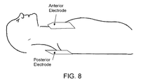
- FIGS. 8, 9A, and 9B show an implementation in which magnetic induction elements are built into electrodes placed in anterior and posterior locations on the thorax.
- FIG. 10 is an enlarged view of the composition of the electrode pad of FIG. 9A .
- FIG. 11 is a block diagram of a synchronous detector implementation.
- FIG. 12 is a block diagram of a filtered-X least mean squares (FXLMS ANC) algorithm.
- FIG. 13 is an implementation using the algorithm of FIG. 12 .
- FIG. 14 shows two spectral power distributions related to the implementation of FIG. 13 .
- FIG. 15 is a block diagram of another implementation.
- FIG. 16 is a block diagram of one implementation of the invention.
- FIG. 17 shows plots of the ECG signal, CPR reference signal, and output of adaptive filter for a normal sinus rhythm.
- FIG. 18 shows plots of the ECG signal, CPR reference signal, and output of adaptive filter for ventricular fibrillation.
- FIG. 19 is a block diagram of a filtered-X least mean squares (FXLMS ANC) algorithm.
- FIG. 20 is a block diagram of an implementation using the algorithm of FIG. 19 .
- FIG. 21 shows two spectral power distributions related to the implementation of FIG. 20 .
- FIG. 1 shows a schematic of a preferred implementation.
- This implementation includes an accelerometer (and accelerometer housing), force sensor built into a pressure pad, and an AED which is electrically connected to the accelerometer and force sensor and contains a display and/or speaker for user feedback.
- the pressure pad provides the structural member on which the accelerometer (and housing) is supported. Neither the accelerometer nor force sensor of the pad are essential to detecting chest release, as other sensors can be used.
- the force sensor can measure force or pressure.
- the accelerometer housing can be shaped similar to a hockey puck and can rest either directly on the patient's sternum or on the pad or other structural member. Preferably the accelerometer is positioned to be over the victim's sternum in the position recommended for chest compressions.
- a force sensor can be placed below (as shown) or above the accelerometer housing. The rescuer presses on the accelerometer housing (or pressure pad) to perform chest compressions.
- the accelerometer senses the motion of the chest during CPR and the force sensor measures the force or pressure applied.
- the AED supplies power to the sensors and digitizes the electrical signals coming from the accelerometer and force sensor. Based on previous calibrations of the sensors, the accelerometer signal is integrated to determine the housing displacement, and the output of the force sensor is converted to standard pressure or force units.
- FIG. 2 shows a sample drawing of the signals recorded during CPR using the implementation of FIG. 1 .
- the acceleration signal is band pass filtered and integrated to derive displacement information (e.g., a displacement signal).
- Compressions (C1-C5) can be detected from the displacement signal.
- the compression rate is calculated from the interval between compressions (e.g. (time of C2 ⁇ time of C1)), and compression depth is measured from the compression onset to peak displacement (e.g. (d1 ⁇ d0)).
- the onset and peak compression values are saved for each compression.
- the pressures at the compression onset and offset are used to determine the force used to achieve a given compression depth.
- the compliance of the chest can be estimated from the compression displacement and the related compression pressure.
- the pressure “p0” is the reference pressure prior to the start of CPR and is related to the resting chest displacement “d0”.
- the pressure “p1” is the pressure required to achieve the displacement “d1”.
- d1 is the displacement at the peak of the compression
- d0 is the displacement at the onset of the compression
- p1 is the pressure at the peak of the compression
- p0 is the pressure at the onset of the compression.
- the chest compliance can be calculated for each compression and averaged to improve the measurement accuracy.
- p3 is the chest release pressure (estimated as the onset pressure of the next compression), and p0 is the resting pressure.
- the chest release pressure can alternately be measured as the minimum pressure point between the two compressions.
- the chest release displacement point is compared to a pre-defined threshold level to determine if the chest was substantially released between two compressions (i.e., released sufficiently to create a pressure in the chest that facilitates venous filling of the heart).
- a combination of voice prompts and display messages can be used to tell the rescuer to more completely release the chest between compressions if the chest release displacement point does not return below the set threshold.
- the chest release displacement value can be averaged to improve the estimate accuracy.
- the comparison to the threshold level could also be done via “voting” logic such as the last x out of y values exceed the set threshold and trigger the release of chest feedback.
- the CPR release of chest algorithm continually runs while the rescuer performs CPR and provides immediate feedback if the rescuer does not release the chest at any time during the resuscitation.
- the threshold level is preferably adjusted dynamically as a function of the calculated chest compliance. For patients with a lower compliance, the threshold can be increased since increased force will have little or no effect on displacement. For patients with higher compliance, the threshold may need to be decreased.
- the calculated estimate of chest compliance can also be used with the output of the force sensor to estimate the depth of chest compression.
- the output of the accelerometer could be used with the output of the force sensor during an initial time interval to calculate an estimate of chest compliance. Thereafter, the estimated chest compliance could be used to convert the force measurement into an estimated depth of chest compression.
- FIG. 3 shows another implementation wherein the force sensor is replaced with a mechanical or electrical switch.
- the rescuer performs CPR by pressing on the switch/housing assembly.
- the switch is activated based on the forces used with CPR compressions and deactivated when a compression is released.
- the switch may provide for bistable positional states such as in a domed switch that when depressed would provide tactile feedback to the hand of the rescuer upon the start of the compression (dome collapse) and at the end of compression (dome return).
- the switch vibration associated with the transition between the two states may also be sufficient to provide an audible feedback to the rescuer as well. If the compression release vibration is heard and/or felt, the chest can be considered by the rescuer to have been released.
- FIG. 4 shows the acceleration, derived displacement, and switch output signals during a sample of CPR.
- Each compression is identified at the top of the diagram (C1-C5).
- the compression interval, rate, and depth are measured from the acceleration signal.
- the dashed line overlaying the switch output curve indicated the force on the puck assembly and is drawn to show the actuation of the switch when the force curve exceeds that activation threshold (solid straight line).
- Time t1 shows the actuation of the switch and time t2 shows the release of the switch.
- the compression switches (ON) at time t3, but does not switch off at time t4 because the force on the chest does not go below the trigger threshold.
- the acceleration signal shows that chest compressions are continuing, but the switch indicates that the chest is not being substantially released. When chest release is not occurring, the AED can audibly and/or visually prompt the user to release the chest.
- FIG. 5 depicts the acceleration, velocity and displacement for a single compression/decompression cycle.
- the input signal from the acceleration sensor as shown in the block diagram in FIG. 6 , is conditioned and filtered to minimized artifact and noise and is input to an A/D converter.
- the A/D converter is then read by the microprocessor.
- the points of interest in the acceleration waveform are as follows:
- A0 is the point of maximum acceleration during the compression downstroke.
- A-2 is the compensatory small upstroke that rescuers often do just prior to the initiation of the compression downstroke and marks the initiation point of the compression downstroke.
- A-1 is the point of maximum acceleration of the compression downstroke.
- A1 is the point of maximum deceleration on the decompression upstroke.
- A2 is a small upward release when the rescuer's hands are slightly lifted from the patient's sternum during an optimum compression cycle.
- A-3 and A3 are inflection points where the signal deviates from baseline.
- SA0 and SA1 are the slopes of the acceleration of the line segments on each side of A0.
- SV0 and SV1 are the slopes of the line segments ( ⁇ acceleration) as shown on the velocity curve.
- VMax is the maximum velocity achieved during the compression downstroke.
- A0 can be detected by a number of means.
- One method is to band pass filter the acceleration signal to produce maximum output signal amplitude of signals having a slope most closely approximating those observed in real compression signals.
- the band pass output is then input to a threshold detection function. If the signal amplitude is larger than the threshold, then SA0 has been detected.
- the threshold itself may be dynamically adjusted in amplitude to minimize susceptibility to noise and interference. For instance, if out of band noise such as 60 Hz interference is detected, then the threshold may be increased.
- the threshold may also be gradually lowered following an SA0 detection such that the probability of detection is increased for signals that occur at the expected interval and is decreasing for false signals that may occur immediately subsequent to the detection.
- TriangleA0 refers to the triangle formed by the A-1, A0 and A1 fiducial points (in gray in FIG. 5 .).
- triangles are then parameterized using such morphological characteristics as width, amplitude, area, center of mass, skewness, height/width ratio, etc.
- TWR triangular width ratio
- the acceleration signal is integrated beginning at inflection point A-3 and ending just subsequent to A3 in order to calculate the velocity.
- the same analysis is used to calculate the fiducial points V-2, VMax, V0 and V1, as well as TAR, TAMPR and TWRs for the velocity curve.
- the velocity curve segment is integrated a second time to calculate displacement.
- Displacement values D-3 and D3 and DMax are calculated.
- the device can prompt the rescuer if the depth of compressions are not sufficient.
- VMax the user can be prompted to deliver a ‘sharper’ more rapid pulse to improve hemodynamics.
- End tidal carbon dioxide (EtCO2) measurements are taken during the course of CPR. Visual and/or audible prompting from the device can encourage the rescuer to increase rate and depth of compressions to improve hemodynamics.
- the calculated parameters of width, amplitude, area, center of mass, skewness, height/width ratio, TAR, TAMPR and TWR for both the acceleration and the velocity as well as ⁇ D are used to make a decision on whether the chest was released.
- the methods used may be standard decision logic (IF-THEN-ELSE) or may involve methods such as fuzzy-logic decision methodology or statistical estimation such as Bayesian methods.
- ⁇ D alone would not be used to determine chest release, but nonetheless the signal processing methods have made it possible with this method to be able to measure ⁇ D without the use of switches or force sensors.
- Final determination of compression release can be withheld for a number of compression cycles to measure longer term trending of the parameters. For example, the rescuer may have momentarily had to pause to wipe their brow.
- a velocity sensor is used to determine the motion parameters.
- One of many possible techniques for sensing velocity is to use magnetic induction to generate a voltage proportional to the relative velocity between a magnet and coil.
- the configuration is shown in FIG. 8 .
- the magnet may take the form of a permanent magnet, but preferably it is an electromagnet.
- FIGS. 9A and 9B a defibrillation pad is placed on the left thorax and another defibrillation pad is placed on the victim's back in the left scapular area. These are optimal locations for defibrillation and provide a good placement to generate magnetic flux changes proportional to sternal displacement.
- the coils are incorporated directly into the outer edge of each of the defibrillation electrodes.
- a separate backboard panel may be supplied which is placed under the patient and contains the receiving coil.
- the use of an electromagnet serves two main purposes: it can be used to calibrate the setup after the electrodes have been applied to the patient and they can be used to provide a synchronous modulation/demodulation of the signal to improve accuracy and minimize susceptibility to noise and artifact.
- the defibrillation electrodes can be constructed with a conventional configuration.
- An electrically conductive sheet of material that delivers defibrillation current to the patient is backed with an insulating thin foam material, and a slightly adhesive conductive gel coupling agent adheres the conductive sheet to the patient's skin.
- the foam backing also forms an approximately 0.5 to 1.0 inch border around the active conductive area.
- the magnetic coil element can be added onto the foam backing and becomes part of the border area, as shown in FIG. 10 .
- the device e.g., AED
- the device can be provided with circuitry for determining whether or not the electrodes have been properly applied to the patient.
- the method currently employed by most manufacturers of defibrillators is to use a small amplitude, high frequency signal ( ⁇ 2 microamps, 60 KHz) to measure impedance.
- the electrodes are determined to be applied when the impedance falls into the physiologic range.
- the device can prompt the rescuer to stand clear.
- the device will perform calibration of the velocity sensor.
- a time-varying signal typically a ramp or sine wave of several frequencies of interest, such as the modulation frequency, is applied to the electromagnet and the signal is measured at the receiving coil. From this, gain and offset coefficients can be calculated for use during the CPR event.
- This calibration step allows for improved accuracy with patients of varying chest sizes and in the presence of any nearby magnetically conductive surfaces or objects.
- a synchronous detector can be employed to minimize susceptibility to noise and artifact as shown in the block diagram in FIG. 11 .
- a sine wave carrier frequency of 500 Hz or more is supplied to the electromagnet coil to generate an oscillating magnetic field that, in turn, induces a voltage on the receiving coil. Chest compressions vary the field intensity at the receiving coil, thus causing an amplitude modulation of the carrier.
- a band pass filter immediately subsequent to signal reception reduces interference outside the range of the carrier frequency such as AC magnetic interference.
- phase lock loop is used for carrier regeneration, but since the transmitter and receiver are in the same device, the transmission carrier can be used for detection as well, as long as circuitry is provided for phase adjustment of the demodulation signal.
- Multiplexer Si combined with the demodulation signal, causes rectification of the signal, which can then be low pass filtered to recover the compression velocity waveform.
- a synchronous AM demodulator can be employed with an analog multiplier stage.
- the velocity signal may then be used to reduce artifacts in the ECG signal. This is accomplished by first time-aligning the ECG and velocity signal by such methods as cross-correlation techniques known to those skilled in the art. This will provide alignment of the two signals relative to the compressions. Then, preferably, adaptive filtering methods are used such as those involved in the minimization of the mean-squared error between the ECG and the velocity.
- FIG. 12 shows a block diagram of the filtered-X least mean squares (FXLMS ANC) algorithm, as developed by Widrow and Burgess.
- P(z) represents the unknown plant through which the signal x(n) is filtered.
- Digital filter W(z) is adaptively adjusted to minimize the error signal e(n).
- x(n) is the unfiltered ECG signal
- P(z) is eliminated from the diagram
- d(n) is approximated with the chest compression velocity signal v(n).
- ⁇ (n) is an instantaneous estimate of the mean square error (MSE) gradient at time n equal to ⁇ 2v(n) e(n).
- MSE mean square error
- H(z) variable cutoff low pass filter
- an FFT is performed on v(n) and input into a cutoff frequency estimation (CFE) procedure that determines the optimal cutoff frequency, fC, for the lowpass filter.
- CFE cutoff frequency estimation
- the decision is based on calculating the frequency, not to exceed 5 Hz, below which 80% of the waveform energy is present, but this percentage may vary and additional decision logic may be employed.
- an FFT may also be calculated for x(n), also input to the CFE procedure.
- FIG. 15 A simpler though related implementation is shown in FIG. 15 , in which the CFE procedure is used to calculate the cutoff frequency for a high pass filter.
- an FFT is performed on v(n) and input into a cutoff frequency estimation (CFE) procedure that determines the optimal cutoff frequency, fC, for, in this case, a high pass filter.
- the decision is based on calculating the frequency, not to exceed 5 Hz, below which 80% of the waveform energy is present, but this percentage may vary and additional decision logic may be employed.
- An FFT may also be calculated for x(n), and also input to the CFE procedure and the optimal high pass cutoff frequency can be determined by the methods described in the previous paragraph. For instances when the spectral energy of the compression artifact is distinct from the ECG signal, this method will have a performance equivalent to the FXLMS just described; its performance will be somewhat inferior when the spectra of the ECG and compression artifact overlap, however.
- the front end of an AED acquires both the ECG signal and the CPR signal, which is the velocity of compression of the chest. If chest displacement or acceleration are measured instead of velocity, velocity can be mathematically acquired via one or more integration or differentiation operations from the measurement signal.
- the velocity signal undergoes pre-processing, and is then fed to an adaptive filter.
- the pre-processing is a normalization of the velocity signal so that the signal supplied to the adaptive filter is limited to be within 0 and 1. But normalization is not required.
- a time-aligning process is performed on the ECG and the reference signal by such methods as cross-correlation. This provide alignment of the two signals relative to the compressions so that the input signals of the adaptive filter are better aligned. But this aligning process is not required.
- Other preprocessing can be applied to the velocity signal to improve the performance of the adaptive filter.
- x(n) and y(n) are the input and the output of the adaptive filter H, which can be an FIR filter, an IIR filter, or another type of filter.
- h(n) is a vector containing the filter coefficients
- m is a vector containing the step sizes for each filter coefficients
- e(n) is the estimated ECG signal
- X(n) is a vector containing the input data.
- the estimated ECG signal is computed by subtracting the filter output y(n) from the measured ECG signal (containing artifact).
- the adaptive filter When the difference between the filter output y(n) and the measured ECG s(n) is beyond a threshold, the adaptive filter will reset its coefficients so that the system will not become unstable.
- FIG. 17 shows samples of the performance of the adaptive filter of FIG. 16 in response to a normal sinus rhythm.
- the signal in (a) is the ECG signal with CPR artifact.
- the signal in (b) is the compression velocity used as the reference signal.
- the signal in (c) is the output of the adaptive filter.
- FIG. 18 shows samples of the performance of the adaptive filter of FIG. 16 during ventricular fibrillation.
- the signal in (a) is the ECG signal with CPR artifact.
- the signal in (b) is the compression velocity used as the reference signal.
- the signal in (c) is the output of the adaptive filter.
- FIG. 16 As shown in both FIG. 17 and FIG. 18 , the implementation of FIG. 16 is able to suppress the CPR artifacts embedded in the measured ECG signals (a).
- the CPR artifact is nearly, if not completely, removed in the estimated ECG signal (c).
- the velocity signal (b) used as a reference signal is clearly correlated with the CPR artifacts in the measured ECG signals (a).
- the adaptive filter assumes that the artifact in the signal is correlated with the reference signal and uncorrelated with the desired signal (estimated ECG). It thus adaptively estimates the artifact using the reference signal and subtracts the estimated artifact from the measured ECG signal.
- results shown in FIG. 17 are based on a 0th-order FIR filter, which simply scales the current sample of the ECG signal adaptively.
- the CPR artifact was significantly reduced, if not completely removed. This implementation thus combines simplicity and efficiency in its performance.
- the speed of adaptation convergence is usually controlled by a step-size variable.
- a faster convergence requires a larger step size, which usually tends to make the filter less stable.
- the automatic resetting mechanism of some implementations can dynamically change the step size and thus improve the relation of convergence and stability.
- the coefficients of the filter are updated in a sample-by-sample manner.
- the changes of the coefficients, i.e., h(n)-h(n ⁇ 1) is proportional to the product of the step size and the reference signal.
- the amplitude of the reference signal can thus affect the stability and convergence of the filter.
- the pre-processing of the reference signal can therefore enhance the performance of the filter by adjusting the reference signal.
- a time-aligning process is performed on the ECG and velocity signals by such methods as cross-correlation. This provide alignment of the two signals relative to the compressions. Then, preferably, adaptive filtering methods are used such as those involved in the minimization of the mean-squared error between the ECG and the velocity.
- a processing unit could be provided for detecting when compressions are being applied and automatically turning on the adaptive filter.
- the output of the adaptive filter i.e., the ECG signal with artifact reduced
- VF detection algorithm e.g., a shock advisory algorithm
- AED automatic external defibrillator
- An error signal could be produced that is representative of the difference between the ECG input and ECG output of the adaptive filter.
- This error signal would give a measure of the amount of CPR artifact in the signal, and it would be useful as a means of modifying the subsequent processing of the ECG. For instance, if the artifact level gets high enough (e.g., higher than a first threshold), the VF detection algorithm thresholds could be increased to make it more resistant to any CPR artifact that still remained in the ECG signal. If the level got even higher (e.g., higher than a second threshold higher than the first threshold), the VF detection could be shut off entirely.
- the filter output is presented graphically on the display of a defibrillator or other medical device incorporating an electro-cardiographic function.
- the filter output may also be printed on a strip-chart recorder in the medical device.
- the filter output may provide the input signal for subsequent signal processing performed by the processing means.
- the purpose of such signal processing may take the form of QRS detection, paced beat detection during pacing, arrhythmia analysis, and detection of ventricular fibrillation or other shockable rhythms.
- Spectral analysis could be performed on the error signal, and based on the major bands of frequency content of the error signal, the pre-filtering of the ECG signal prior to the VF detection can be adjusted. For instance, if the error signal is found to reside primarily in the 3-5 Hz band, additional filtering can be provided in that band prior to input into the VF detection (or other ECG processing) algorithm.
- methods of adaptive channel equalization may be employed to ameliorate both synchronization and phase errors in the velocity waveform.
- Kalman filtering techniques may also be employed to improve performance of the filter when rescuer performance of chest compressions changes over time and is better modeled as a non-stationary process.
- Time alignment of the ECG and velocity signal may also be accomplished by such methods as cross-correlation techniques known to those skilled in the art. This will provide alignment of the two signals relative to the compressions. Then, preferably, adaptive filtering methods are used such as those involved in the minimization of the mean-squared error between the ECG and the velocity.
- FIG. 19 shows a block diagram of the filtered-X least mean squares (FXLMS ANC) algorithm, as developed by Widrow and Burgess.
- P(z) represents the unknown plant through which the signal x(n) is filtered.
- Digital filter W(z) is adaptively adjusted to minimize the error signal e(n).
- x(n) is the unfiltered ECG signal
- P(z) is eliminated from the diagram
- d(n) is approximated with the chest compression velocity signal v(n).
- ⁇ (n) is an instantaneous estimate of the mean square error (MSE) gradient at time n equal to ⁇ 2v(n) e(n).
- MSE mean square error
- Stability and accuracy of the FXLMS ANC algorithm can be improved by adding a variable cutoff low pass filter H(z) to eliminate frequency components in the ECG not related to the chest compression artifact.
- H(z) the spectral energy of the chest compression artifact is predominately lower than those of the ECG.
- a cutoff frequency of approximately 3 Hz is adequate in many cases, but this may vary from patient to patient and among different rescuers performing chest compressions.
- an FFT is performed on v(n) and input into a cutoff frequency estimation (CFE) procedure that determines the optimal cutoff frequency, fC, for the lowpass filter.
- CFE cutoff frequency estimation
- the decision is based on calculating the frequency, not to exceed 5 Hz, below which 80% of the waveform energy is present, but this percentage may vary and additional decision logic may be employed.
- an FFT may also be calculated for x(n), also input to the CFE procedure.
- ICG impedance cardiographic
- IPG impedance pneumographic
- pulse oximetry pulse oximetry
- the adaptive filter can be used to minimize the cross-correlation of the adaptive-filter output with the reference signal or the cross-correlation of the adaptive-filter output with the measured ECG signal.
- the invention includes an external defibrillator, as a device for assisting delivery of CPR could be provided without defibrillation capability.
- the CPR assistance device could even be a pocket device that is for assisting with manual delivery of CPR.
- chest compliance be determined, or that substantial release of the chest be determined, or that a particular type of sensor (e.g., accelerometer, force sensor, velocity sensor), or combination of sensors, be used, or that there be analysis of features of a motion waveform, or that maximum velocity be estimated, or that artifacts in detected ECG signals be reduced.
- a particular type of sensor e.g., accelerometer, force sensor, velocity sensor
- sensors e.g., accelerometer, force sensor, velocity sensor
Abstract
An apparatus for assisting a rescuer in performing chest compressions during CPR on a victim, the apparatus comprising a pad or other structure configured to be applied to the chest near or at the location at which the rescuer applies force to produce the chest compressions, at least one sensor connected to the pad, the sensor being configured to sense movement of the chest or force applied to the chest, processing circuitry for processing the output of the sensor to determine whether the rescuer is substantially releasing the chest following chest compressions, and at least one prompting element connected to the processing circuitry for providing the rescuer with information as to whether the chest is being substantially released following chest compressions.
Description
This application is a continuation application of and claims priority to U.S. application Ser. No. 14/512,167, filed Oct. 10, 2014, which application is a continuation application of and claims priority to U.S. application Ser. No. 13/872,033, filed Apr. 26, 2013, now issued as U.S. Pat. No. 8,862,228, which application is a continuation application of and claims priority to U.S. application Ser. No. 10/786,359, filed Feb. 24, 2004, now abandoned, which application is a continuation-in-part of and claims priority to U.S. application Ser. No. 10/704,366, filed on Nov. 6, 2003, now issued U.S. Pat. No. 7,220,235. All are hereby incorporated by reference.
This invention relates to the devices for assisting cardiac resuscitation.
This invention relates to the field of cardiac resuscitation, and in particular to devices for assisting rescuers in performing chest compression during cardio-pulmonary resuscitation (CPR). Chest compression during CPR is used to mechanically support circulation in subjects with cardiac arrest, by maintaining blood circulation and oxygen delivery until the heart is restarted. The victim's chest is compressed by the rescuer, ideally at a rate and depth of compression in accordance with medical guidelines, e.g., the American Heart Association (AHA) guidelines. One key step for creating blood flow through the heart is to release the chest adequately after each chest compression. The chest should be released sufficiently to create a negative pressure in the chest, to facilitate venous filling of the heart and increased blood flow upon the next chest compression. If the chest is not released adequately, a positive thoracic pressure will remain which will hinder venous return and right atrial filling. Other key CPR parameters are maximal velocity of compression, compression depth, and average velocity. Compression depth and average velocity, together, provide good indication of potential blood flow volume. Maximal velocity of compression is an important factor in proper mitral valve closure and higher blood flow volume.
Sensors have been suggested for detecting the depth of chest compression. An accelerometer (with its output integrated to estimate depth) was disclosed, for example, in Freeman U.S. application Ser. No. 09/794,320, U.S. Pat. No. 6,306,107 and U.S. Pat. No. 6,390,996. Force (pressure) sensors were disclosed, for example, in Groenke U.S. Pat. No. 6,125,299. Force sensors provided no way of determining absolute displacement, as the compliance of the thoracic cage varies considerably from person to person. Accelerometers do not provide an indication of whether or not the chest is being released. They calculate displacement by double integration, which can result in a significant DC offset. U.S. Pat. No. 6,306,107 attempted to address the DC offset problem by incorporating a force sensor as a switch to indicate onset and conclusion of compression. The prior art has also employed mechanical pressure gauges to indicate to the rescuer the amount of force or pressure being applied to the chest. But these prior art uses of an accelerometer and/or force sensor have not provided a good solution to providing the rescuer with useful feedback as to whether the chest has been sufficiently released. Differences in compliance of the thoracic cage from one individual to another means that each individual will generally be able to support different amounts of force on the sternum without significant displacement occurring.
Increasingly, automated external defibrillators (AEDs) are used by rescuers treating victims of cardiac arrest for the delivery of defibrillatory shocks with the minimum of delay. The algorithms contained in the currently-available AEDs call for ‘hands off’ periods during which electrocardiographic (ECG) analysis is performed by the device and the rescuer withholds compressions. Compressions must be withheld because the accuracy of current rhythm analysis algorithms in AEDs is severely degraded by the artifact induced by the chest compressions. These AEDs also call for the rescuer to check for pulse or for signs of circulation during which time no compressions are performed. It has been shown in several studies that interruptions in the performance of chest compressions of as short a time as 20 seconds can dramatically reduce the probability of the return of spontaneous circulation (ROSC), a key survival measure. Other studies have also shown that the minimum amount of time required for the ‘hands off’ period is 20 seconds. There is therefore a need for the ability of AEDs to perform rhythm analysis while the rescuer continues with the chest compressions uninterrupted.
Resuscitation treatments for patients suffering from cardiac arrest generally include clearing and opening the patient's airway, providing rescue breathing for the patient, and applying chest compressions to provide blood flow to the victim's heart, brain and other vital organs. If the patient has a shockable heart rhythm, resuscitation also may include defibrillation therapy. The term basic life support (BLS) involves all the following elements: initial assessment; airway maintenance; expired air ventilation (rescue breathing); and chest compression. When all three (airway breathing, and circulation, including chest compressions) are combined, the term cardiopulmonary resuscitation (CPR) is used.
Current automated ECG rhythm analysis methods interrupt cardiopulmonary resuscitation (CPR) to avoid artifacts in the ECG resulting from chest compressions. Long interruptions of CPR have been shown to result in higher failure rate of resuscitation. Studies have reported that the discontinuation of precordial compression can significantly reduce the recovery rate of spontaneous circulation and the 24-hour survival rate. Y. Sato, M H. Weil, S. Sun, W. Tang, J. Xie, M. Noc, and J. Bisera, Adverse effects of interrupting precordial compression during cardiopulmonary resuscitation, Critical Care Medicine, Vol. 25(5), 733-736 (1997). Yu et al., 2002. Circulation, 106, 368-372 (2002), T. Eftestol, K. Sunde, and PA. Steen, Effects of Interrupting Precordial Compressions on the Calculated Probability of Defibrillation Success During Out-of-Hospital Cardiac Arrest, Circulation, 105, 2270-2273, (2002).
Management of breathing is another important aspect of the CPR process. Typical methods of monitoring breathing employ some form of impedance pneumography which measure and track changes in the transthoracic impedance of the patient. Currently, however, chest compressions result in significant artifact on the impedance signals, resulting in impedance-based pneumographic techniques as unreliable indicators of lung volume during chest compressions.
Adaptive filters have been attempted as a way of removing chest-compression artifacts in the ECG signal. S O. Aase, T. Eftestol, J H. Husoy, K. Sunde, and PA. Steen, CPR Artifact Removal from Human ECG Using Optimal Multichannel Filtering, IEEE Transactions on Biomedical Engineering, Vol. 47, 1440-1449, (2000). A. Langhelle, T. Eftestol, H. Myklebust, M. Eriksen, B T. Holten, P A. Steen, Reducing CPR Artifacts in Ventricular Fibrillation in Vitro. Resuscitation. March; 48(3):279-91 (2001). J H. Husoy, J. Eilevstjonn, T. Eftestol, S O. Aase, H Myklebust, and PA. Steen, Removal of Cardiopulmonary Resuscitation Artifacts from Human ECG Using an Efficient Matching Pursuit-Like Algorithm, IEEE Transactions on Biomedical Engineering, Vol 49, 1287-1298, (2002). H R. Halperin, and R D. Berger, CPR Chest Compression Monitor, U.S. Pat. No. 6,390,996 (2002). Aase et al. (2000) and Langhelle et al. (2001) used the compression depth and thorax impedance as reference signals for their adaptive filter. Husoy et al. (2002) extended this study by using a matching pursuit iteration to reduce the computational complexity; however, their results are usually computationally intensive, such as involving the calculation of a high order inverse filter. Halperin et al. (2002) proposed a frequency-domain approach using the auto- and the cross-spectrum of the signals and a time-domain approach using a recursive least square method for adaptive filtering the ECG signal. In both approaches, intensive computations are required.
There are numerous references available on adaptive filters. E.g., S. Haykin, Adaptive Filter Theory, Third Edition, Upper Saddle River, N.J., USA. Prentice-Hall, 1996
In a first aspect, the invention features an apparatus for assisting a rescuer in performing chest compressions during CPR on a victim, the apparatus comprising a pad or other structure configured to be applied to the chest near or at the location at which the rescuer applies force to produce the chest compressions, at least one sensor connected to the pad, the sensor being configured to sense movement of the chest or force applied to the chest, processing circuitry for processing the output of the sensor to determine whether the rescuer is substantially releasing the chest following chest compressions, and at least one prompting element connected to the processing circuitry for providing the rescuer with information as to whether the chest is being substantially released following chest compressions.
Preferred implementations of this aspect of the invention may incorporate one or more of the following. The pad or other structure may be a pad to which force is applied by rescuer. The sensor may include an accelerometer. The sensor may include a force (or pressure) sensor. The sensor may include a velocity sensor. The sensor may include both a force (or pressure) sensor and an accelerometer or velocity sensor. The prompting device may include a speaker for delivering an audible message to the rescuer. The prompting device may include a display for delivering a visual message to the rescuer. The apparatus may be part of an external defibrillator. The external defibrillator may be an AED. The processing circuitry may include a digital processor executing software. Determining whether the rescuer is substantially releasing the chest may comprise analyzing motion of the chest. Analyzing motion of the chest may comprise analyzing features or the shape of a waveform representing chest motion. The apparatus may comprise both a sensor to sense movement of the chest and a sensor to sense force applied to the chest, and the processing circuitry may use outputs of both sensors to provide information representative of chest compliance. The information representative of chest compliance may be used to determine a level of applied pressure/force that corresponds to a substantial release of the chest.
In a second aspect, the invention features an apparatus for assisting a rescuer in performing chest compressions during CPR on a victim, the apparatus comprising a pad or other structure configured to be applied to the chest near or at the location at which the rescuer applies force to produce the chest compressions, and at least one velocity sensor connected to the pad, the velocity sensor being configured to sense the velocity of movement of the chest.
Preferred implementations of this aspect of the invention may incorporate one or more of the following. The apparatus may further comprise processing circuitry for processing the output of the velocity sensor to estimate the displacement of the chest. The processing circuitry may have the capability to integrate an output of the velocity sensor. The velocity sensor may be configured to be located approximately adjacent to the location at which the body is compressed. The velocity sensor may be configured to be positioned to sense the relative velocity between opposite surfaces of the chest. The velocity sensor may comprise a conductor and a magnet, and velocity may be sensed by sensing the current induced in the conductor by relative motion between the conductor and the magnet. The magnet may comprise one of a permanent magnet and an electromagnet. The conductor and magnet may be positioned on opposite surfaces of the chest. The conductor may comprise a coil that is unitary with a defibrillation electrode pad. The conductor and magnet each may comprise a coil that is unitary with a defibrillation electrode pad. The magnet may comprise an electromagnet and the electromagnet may produce a magnetic field that oscillates at a frequency greater than 1 KHz, and may further comprise coil detection circuitry to which the coil is connected, wherein the coil detection circuitry may be capable of synchronously demodulating the detected signal to reduce susceptibility to drift and noise. The apparatus may further comprise circuitry for acquiring ECG signals from the victim, and the processing circuitry may have the capability to process the output of the velocity sensor and the ECG signals to reduce ECG artifacts from chest compressions by use of velocity sensor output.
In a third aspect, the invention features an apparatus for assisting a rescuer in performing chest compressions during CPR on a victim, the apparatus comprising a pad or other structure configured to be applied to the chest near or at the location at which the rescuer applies force to produce the chest compressions, at least one motion sensor connected to the pad, the motion sensor being configured to sense movement of the chest, processing circuitry for processing the output of the motion sensor to estimate the maximum velocity of compression of the chest, and at least one prompting device connected to the processing circuitry for providing the rescuer with information representative of the maximum velocity of compression. In preferred implementations of this aspect of the invention, the motion sensor may comprise a velocity sensor.
In a fourth aspect, the invention features a method of determining chest compression during CPR, the method comprising applying a motion sensor to the chest of a patient at a location near or at the location at which a rescuer applies force to produce chest compressions, determining chest displacement from analysis of features of the motion waveform produced by the motion sensor.
Preferred implementations of this aspect of the invention may incorporate one or more of the following. The motion sensor may be a velocity sensor. The motion sensor may be an accelerometer. The method may further comprise deciding from the analysis of features of the acceleration waveform whether or not a rescuer has sufficiently released the patient's chest. The method may further comprise processing the output of the accelerometer to provide velocity and acceleration waveforms. The method may further comprise processing the output of the accelerometer to provide velocity and acceleration waveforms, and analyzing the velocity and acceleration waveforms to determine whether or not a rescuer has sufficiently released the patient's chest. The analysis of velocity waveforms may include determining the maximal velocity of compression. Determining chest displacement from analysis of features may comprise determining onset and completion times for a compression cycle from the features of the waveforms. Determining chest displacement may further comprise integrating the acceleration waveform over a time segment defined by the onset and completion times. The method may further comprise analyzing the features of the upstroke portion of the waveforms to determine whether there has been sufficient release of the chest. The method may further comprise prompting a rescuer based as to whether compressions are within desired limits on compression depth and compression release. The prompts to the rescuer may be based on multi-cycle trends, so that they are not immediately influenced by the rescuer taking a brief break in the application of CPR. The method may further comprise determining chest compliance, and using the determined chest compliance to adjust the level of pressure/force that the rescuer is permitted to apply at the end of a compression stroke without being prompted as to insufficiently releasing the chest. The features determined from the waveforms may include one or more of the following: width, amplitude, area, center of mass, skewness, height/width ratio, TAR, TAMPR and TWR. The features may be used to make a decision as to whether the chest of the victim has been sufficiently released. Decisions may be made using either standard decision logic, fuzzy-logic decision methodology, or statistical estimation.
In a fifth aspect, the invention features a method of analyzing ECG signals during application of CPR, the method comprising detecting ECG signals during application of chest compressions, detecting the output of a sensor from which information on the velocity of chest compressions can be determined, and using the information on the velocity to reduce at least one signal artifact in the ECG signal resulting from the chest compressions.
Preferred implementations of this aspect of the invention may incorporate one or more of the following. The sensor may be a velocity sensor, and the information on the velocity may be determined from the velocity sensor. The sensor may be an accelerometer, and the information on the velocity may be determined from integration of the output of the accelerometer. Using the information on the velocity to reduce at least one signal artifact in the ECG signal may comprise time aligning the ECG signals with the velocity. Using the information on the velocity to reduce at least one signal artifact in the ECG signal may comprise an adaptive filter that is adjusted to remove chest compression artifacts. Using the information on the velocity to reduce at least one signal artifact in the ECG signal may comprise feed forward active noise cancellation. Using the information on the velocity to reduce at least one signal artifact in the ECG signal may comprise determining a cutoff frequency for a filter that separates the ECG signal from chest compression artifacts.
In a sixth aspect, the invention features an apparatus for assisting a rescuer in performing chest compressions during CPR on a victim, the apparatus comprising a pad or other structure configured to be applied to the chest near or at the location at which the rescuer applies force to produce the chest compressions, at least one motion sensor connected to the pad, the motion sensor being configured to sense movement of the chest, at least one force (or pressure) sensor connected to the pad, the force sensor being configured to sense force applied to the chest, and processing circuitry for processing the output of the motion sensor and force sensor to estimate the compliance of the chest.
Preferred implementations of this aspect of the invention may incorporate one or more of the following. The estimated compliance and the output of the force sensor may be used to determine the depth of compression of the chest. The motion sensor may be an accelerometer, and the output of the accelerometer may be used primarily for estimating chest compliance, and compression depth during CPR may be estimated by using the estimated compliance to convert the output of the force sensor into estimated compression depth. The output of the accelerometer may be used during limited time intervals for estimating chest compliance, and outside of those limited time intervals chest compression may be determined from the estimated compliance and the output of the force sensor without substantial use of the output of the accelerometer. The estimated compliance and the output of the force sensor may be used to determine whether the chest has been substantially released.
In a seventh aspect, the invention features an apparatus for assisting a rescuer in performing chest compressions during CPR on a victim, the apparatus comprising a pad or other structure configured to be applied to the chest near or at the location at which the rescuer applies force to produce the chest compressions, at least one bistable mechanical element that when depressed provides tactile feedback to the hand of the rescuer upon the start of a compression and at the end of a compression.
Preferred implementations of this aspect of the invention may incorporate one or more of the following. The mechanical element may comprise a dome that collapses under pressure and returns to a dome shape on release of pressure. The bistable mechanical element may further provide audible feedback at least at the end of a compression. The tactile feedback at the end of a compression may occur at approximately an applied force corresponding to substantial release of the chest, so that the tactile feedback serves as feedback to the rescuer that the chest has been substantially released.
The invention provides numerous advantages. It provides a more accurate and detailed measure of compressions during CPR, e.g., by analyzing such compression/decompression cycle parameters as compression velocity and completeness of decompression release. And features of the velocity and acceleration waveforms may be analyzed to maximize CPR performance. E.g., the invention permits analysis of maximal velocity of compression, which is an important factor in proper mitral valve closure and higher blood flow volume.
The invention may obviate the need for a secondary information channel, e.g., a force sensor, to provide the accuracy necessary for the use of acceleration to accurately measure displacement. The invention includes new methods for the analysis of the acceleration waveform that allow for decreased offset drift and improved displacement accuracy. The methods also provide for the ability to determine parameters relating to the quality of the compression/decompression cycle by morphological analysis of the acceleration and velocity waveform. Multiple parameters may be determined via the analysis and then combined in making a decision regarding chest release or other generalized descriptor of compression/decompression quality. The methods used may include standard decision logic (e.g., IF-THEN-ELSE) or may involve methods such as fuzzy-logic decision methodology or statistical estimation such as Bayesian methods.
Direct physiological measurements of perfusion and oxygenation, such as end-tidal carbon dioxide (EtCO2) and pulse oximetry, can provide additional feedback to the CPR control algorithm.
By determining chest compliance, some implementations of the invention overcome the difficulty of using a pressure/force sensor for determining the onset and release of compression. The compliance of the thoracic cage varies from person to person, and therefore each individual will generally be able to support different amounts of force on the sternum without any displacement occurring. In some implementations of the invention, compliance is estimated from measurements of force (or pressure) and chest motion during compressions. The estimated compliance can be used to adapt the chest-released force threshold to patients with differing chest compliance. Without adapting the threshold to the victim's chest compliance, the chest-released force threshold tends to have to be set quite low, to assure substantial release even on patients with large compliance. This can result in requiring the rescuer to release nearly all force from the chest, interfering with the process of CPR itself and confusing the rescuer with what appears to be irrelevant and interfering commands.
Using a velocity sensor (as proposed with some aspects of the invention), can provide a more accurate and less noise sensitive measure for determining displacement. It requires only one integration to calculate displacement from velocity, thus reducing offset error, and it requires only one differentiation to calculate acceleration thus reducing high frequency noise susceptibility. Additionally, velocity in this implementation is a differential configuration that measures relative velocity between the front and back of the thorax, unlike acceleration which is inertial and whose motion is relative to the Earth. Differential velocity measurement provides a significantly improved performance during patient transport such as in an ambulance or on an airplane. In fact, the vibration and motion may make the acceleration for the most part unusable in these situations.
Magnetic induction may be used to generate a voltage proportional to the relative velocity between a magnet and coil. The magnet may take the form of a permanent magnet, but preferably it is an electromagnet. The use of an electromagnet serves two main purposes: it can be used to calibrate the setup after the electrodes have been applied to the patient, and it can be used to provide a synchronous modulation/demodulation of the signal to improve accuracy and minimize susceptibility to noise and artifact.
The magnetic pickup and induction coils may be incorporated into defibrillation pads. One defibrillation pad can be placed on the left thorax and another defibrillation pad can be placed on the victim's back in the left scapular area. These are excellent locations for defibrillation and provide a good placement to generate magnetic flux changes proportional to sternal displacement. The coils can incorporated directly into the outer edge of each of the defibrillation electrodes. Alternatively, if the desired electrode position is anterior/anterior with both electrodes on the front of the chest, a separate backboard panel may be supplied which is placed under the patient and contains the receiving coil.
The invention's use of velocity sensor, which may make it possible to perform ECG analysis without a “hands off” period provides improved filtering and rhythm analysis.
In general the invention features a method of analyzing a physiological (e.g., an ECG) signal during application of chest compressions. The method includes acquiring a physiological signal during application of chest compressions; acquiring the output of a sensor from which information on the velocity of chest compressions can be determined; and using the information on the velocity to reduce at least one signal artifact in the physiological signal resulting from the chest compressions.
Preferred implementations of the invention may incorporate one or more of the following: The physiological signal may be any of a variety of physiological signals, including an ECG signal, an IPG signal, an ICG signal, or a pulse oximetry signal. The sensor may be a velocity sensor, and the information on the velocity may be determined from the velocity sensor. The sensor may be an accelerometer, and the information on the velocity may be determined from integration of the output of the accelerometer. Using the information on the velocity to reduce at least one signal artifact in the physiological signal may comprise time aligning the physiological signal with the velocity. Using the information on the velocity to reduce at least one signal artifact in the physiological signal may comprise using an adaptive filter that may be adjusted to remove chest compression artifacts. The method may include a ventricular fibrillation detection algorithm for processing the physiological signal with reduced artifact to estimate whether a ventricular fibrillation may be present. The method may include a preprocessing step that detects when chest compressions are applied and automatically initiates the adaptive filter. The method may include enabling delivery of a defibrillation shock if the algorithm estimates that ventricular fibrillation is present. A difference signal may be produced, the difference signal being representative of the difference between the physiological signal fed into the adaptive filter and the physiological signal after artifact reduction by the adaptive filter. The difference signal may provide a measure of the amount of artifact in the physiological signal. The difference signal may be used to modify the subsequent processing of the physiological signal. If the difference signal indicates that the amount of artifact exceeds a first threshold, the ventricular fibrillation detection algorithm may be modified to make it more resistant to being influenced by the artifact. If the difference signal indicates that the amount of artifact exceeds a second threshold higher than the first threshold, use of the ventricular defibrillation detection algorithm may be suspended. Spectral analysis may be performed on the difference signal, and adjustments may be made to filtering of the physiological signal based on the outcome of the spectral analysis. The velocity signal may undergo a normalization pre-processing prior to being fed to an adaptive filter. The adaptive filter may include an FIR filter. The adaptive filter may include a zero-th order filter. The adaptive filter may have coefficients that are dynamically controlled by an estimate of the physiological signal. The adaptive filter may have the capability of being automatically reset when the difference between the filter output and the measured physiological signal is beyond a threshold. The automatic reset may be capable of dynamically changing the step size and thus improving the relationship of convergence and stability of the filter. A time-aligning process may be performed on the physiological and velocity signals, wherein the time aligning process aligns the two signals relative to the compressions. The method may include adaptive filtering of the output of the time aligning process, wherein the adaptive filtering reduces the error between the physiological and velocity signals. The adaptive filter may include a Kalman filter. The adaptive filter may employ adaptive equalization.
Among the many advantages of the invention (some of which may be achieved only in some of its various implementations) are the following:
This invention provides excellent techniques for (a) adaptively removing the artifacts induced by CPR in an ECG signal, (b) enhancing an ECG signal for monitoring, and (c) increasing the reliability of ECG rhythm advisory algorithms.
As part of a rhythm advisory algorithm, various implementations of the invention could be incorporated in an ECG monitor, an external defibrillator, an ECG rhythm classifier, or a ventricular arrhythmia detector.
The invention makes it possible to continue performing CPR while ECG data is collected for an ECG rhythm advisory algorithm. This can enhance the result of CPR, leading, for example, to an increase in the success rate of resuscitation.
The invention can also provide a “cleansed” ECG signal output for display to the user of a defibrillator.
The invention also provides for the first time a means of measuring lung volume during chest compressions by impedance-based methods. The method may also be used to filter other physiological signals corrupted by compression-induced artifact, such as impedance cardiography and pulse oximetry.
This invention demonstrates excellent performance at removing the CPR artifact with a zero-th order FIR filter, thus making some implementations of the invention much simpler and faster than the adaptive-filter structures proposed in the prior art.
Pre-processing of the reference signal and an automatic-reset feature make it possible for some implementations of the invention to use a relatively large step size for adaptation, thus making convergence faster and more stable.
Some implementations of the invention achieve excellent performance in CPR-artifact removal at reduced computational cost.
Other features and advantages of the invention will be apparent from the following detailed description and drawings, and from the claims.
There are a great many possible implementations of the invention, too many to describe herein. Some possible implementations that are presently preferred are described below. It cannot be emphasized too strongly, however, that these are descriptions of implementations of the invention, and not descriptions of the invention, which is not limited to the detailed implementations described in this section but is described in broader terms in the claims.
The accelerometer housing can be shaped similar to a hockey puck and can rest either directly on the patient's sternum or on the pad or other structural member. Preferably the accelerometer is positioned to be over the victim's sternum in the position recommended for chest compressions. A force sensor can be placed below (as shown) or above the accelerometer housing. The rescuer presses on the accelerometer housing (or pressure pad) to perform chest compressions. The accelerometer senses the motion of the chest during CPR and the force sensor measures the force or pressure applied. The AED supplies power to the sensors and digitizes the electrical signals coming from the accelerometer and force sensor. Based on previous calibrations of the sensors, the accelerometer signal is integrated to determine the housing displacement, and the output of the force sensor is converted to standard pressure or force units.
Chest Compliance=|(d1−d0)/(p1−p0)|
Where d1 is the displacement at the peak of the compression, d0 is the displacement at the onset of the compression, p1 is the pressure at the peak of the compression, and p0 is the pressure at the onset of the compression. The chest compliance can be calculated for each compression and averaged to improve the measurement accuracy.
Once the patient specific chest compliance is known, it can be used to estimate the absolute displacement of the puck when combined with the instantaneous puck pressure measure from the following equation:
Displacement=compliance*(p−p0)
Displacement=compliance*(p−p0)
Where p is the pressure measured from the puck at a point in time, p0 is the resting puck pressure when there is no compressions or handling by the rescuer. Therefore, the chest release displacement can be estimated by the following equation:
Displacement at the release of chest=compliance*(p3−p0).
Displacement at the release of chest=compliance*(p3−p0).
Where compliance is determined as described above, p3 is the chest release pressure (estimated as the onset pressure of the next compression), and p0 is the resting pressure.
The chest release pressure can alternately be measured as the minimum pressure point between the two compressions.
The chest release displacement point is compared to a pre-defined threshold level to determine if the chest was substantially released between two compressions (i.e., released sufficiently to create a pressure in the chest that facilitates venous filling of the heart). A combination of voice prompts and display messages can be used to tell the rescuer to more completely release the chest between compressions if the chest release displacement point does not return below the set threshold. The chest release displacement value can be averaged to improve the estimate accuracy. The comparison to the threshold level could also be done via “voting” logic such as the last x out of y values exceed the set threshold and trigger the release of chest feedback. The CPR release of chest algorithm continually runs while the rescuer performs CPR and provides immediate feedback if the rescuer does not release the chest at any time during the resuscitation.
Although not necessary, the threshold level is preferably adjusted dynamically as a function of the calculated chest compliance. For patients with a lower compliance, the threshold can be increased since increased force will have little or no effect on displacement. For patients with higher compliance, the threshold may need to be decreased.
The calculated estimate of chest compliance can also be used with the output of the force sensor to estimate the depth of chest compression. Thus, for example, the output of the accelerometer could be used with the output of the force sensor during an initial time interval to calculate an estimate of chest compliance. Thereafter, the estimated chest compliance could be used to convert the force measurement into an estimated depth of chest compression.
In another implementation, the acceleration waveform alone is analyzed without the use of a switch or force sensor. FIG. 5 depicts the acceleration, velocity and displacement for a single compression/decompression cycle. The input signal from the acceleration sensor, as shown in the block diagram in FIG. 6 , is conditioned and filtered to minimized artifact and noise and is input to an A/D converter. The A/D converter is then read by the microprocessor. In FIG. 5 , the points of interest in the acceleration waveform are as follows:
1. A0 is the point of maximum acceleration during the compression downstroke.
2. A-2 is the compensatory small upstroke that rescuers often do just prior to the initiation of the compression downstroke and marks the initiation point of the compression downstroke.
3. A-1 is the point of maximum acceleration of the compression downstroke.
4. A1 is the point of maximum deceleration on the decompression upstroke.
5. A2 is a small upward release when the rescuer's hands are slightly lifted from the patient's sternum during an optimum compression cycle.
6. A-3 and A3 are inflection points where the signal deviates from baseline.
7. SA0 and SA1 are the slopes of the acceleration of the line segments on each side of A0.
8. SV0 and SV1 are the slopes of the line segments (˜acceleration) as shown on the velocity curve.
9. VMax is the maximum velocity achieved during the compression downstroke.
Many algorithms can be used for determination of substantial release of the chest. One algorithm is as follows:
1. Determine fiducial point A0. Completion of the compression determination should approach real time in order to provide maximum benefit to the rescuer. Delays of approximately 1-4 seconds are acceptable and will limit the types of ‘search forward’ algorithms that can be implemented. A0 can be detected by a number of means. One method is to band pass filter the acceleration signal to produce maximum output signal amplitude of signals having a slope most closely approximating those observed in real compression signals. The band pass output is then input to a threshold detection function. If the signal amplitude is larger than the threshold, then SA0 has been detected. The threshold itself may be dynamically adjusted in amplitude to minimize susceptibility to noise and interference. For instance, if out of band noise such as 60 Hz interference is detected, then the threshold may be increased. The threshold may also be gradually lowered following an SA0 detection such that the probability of detection is increased for signals that occur at the expected interval and is decreasing for false signals that may occur immediately subsequent to the detection. Once SA0 has been detected, the algorithm can search forward until it finds the peak amplitude, A0.
2. Searching backwards and forwards from point A0, the points A-3, A-2, A-1, A0, A1, A2 and A3 can be determined.
3. The acceleration signal can then be decomposed into constituent triangles formed from these fiducial points. TriangleA0 refers to the triangle formed by the A-1, A0 and A1 fiducial points (in gray in FIG. 5 .).
4. The triangles are then parameterized using such morphological characteristics as width, amplitude, area, center of mass, skewness, height/width ratio, etc.
5. Area ratios are then calculated for the various triangle pairs. For example the ratio of the areas of TriangleA0 and TriangleA1, Acceleration Triangular Area Ratio(0,1) [TARA(0,1)]
TARA(0,1)=[Area TriangleA0]/[Area of TriangleA1]
TARA(0,1)=[Area TriangleA0]/[Area of TriangleA1]
6. Amplitude ratios are then calculated for the various triangle pairs. Degree of skew is incorporated into the amplitude calculation by incorporating either skewness or center of mass into the calculation for each triangle. For example the ratio of the areas of TriangleA0 and TriangleA1, Triangular Amplitude ratioA(0,1) (TAMPRA(0,1))
TAMPRA(0,1)=[Amplitude of TriangleA0]/[Amplitude of TriangleA1]
TAMPRA(0,1)=[Amplitude of TriangleA0]/[Amplitude of TriangleA1]
7. The same process is repeated for the triangular width ratio (TWR).
8. A rescuer who applies too much downward force during the decompression upstroke will cause incomplete decompression. This downward force opposes the natural elastic force of the thoracic cage and as a result causes a decreased amplitude and elongation of triangleA1 and triangleA2 as shown in FIG. 7 .
9. The acceleration signal is integrated beginning at inflection point A-3 and ending just subsequent to A3 in order to calculate the velocity. The same analysis is used to calculate the fiducial points V-2, VMax, V0 and V1, as well as TAR, TAMPR and TWRs for the velocity curve.
10. The velocity curve segment is integrated a second time to calculate displacement. Displacement values D-3 and D3 and DMax are calculated. Differential displacement, ΔD=D-3−D3 is calculated.
11. Based on DMax, the device can prompt the rescuer if the depth of compressions are not sufficient.
12. Based on VMax, the user can be prompted to deliver a ‘sharper’ more rapid pulse to improve hemodynamics.
13. End tidal carbon dioxide (EtCO2) measurements are taken during the course of CPR. Visual and/or audible prompting from the device can encourage the rescuer to increase rate and depth of compressions to improve hemodynamics.
14. The calculated parameters of width, amplitude, area, center of mass, skewness, height/width ratio, TAR, TAMPR and TWR for both the acceleration and the velocity as well as ΔD are used to make a decision on whether the chest was released. The methods used may be standard decision logic (IF-THEN-ELSE) or may involve methods such as fuzzy-logic decision methodology or statistical estimation such as Bayesian methods. In general, ΔD alone would not be used to determine chest release, but nonetheless the signal processing methods have made it possible with this method to be able to measure ΔD without the use of switches or force sensors.
15. Final determination of compression release can be withheld for a number of compression cycles to measure longer term trending of the parameters. For example, the rescuer may have momentarily had to pause to wipe their brow.
Alternatively, other signal detection and classification methods known to those skilled in the art may be used to determine the relevant morphological features such as those shown in FIG. 7 (CPR with substantial chest release is shown by solid lines; inadequate chest release, by dashed line).
In another implementation, a velocity sensor is used to determine the motion parameters. One of many possible techniques for sensing velocity is to use magnetic induction to generate a voltage proportional to the relative velocity between a magnet and coil. The configuration is shown in FIG. 8 . The magnet may take the form of a permanent magnet, but preferably it is an electromagnet. As shown in FIGS. 9A and 9B , a defibrillation pad is placed on the left thorax and another defibrillation pad is placed on the victim's back in the left scapular area. These are optimal locations for defibrillation and provide a good placement to generate magnetic flux changes proportional to sternal displacement. The coils are incorporated directly into the outer edge of each of the defibrillation electrodes. Alternatively, if the desired electrode position is anterior/anterior with both electrodes on the front of the chest, a separate backboard panel may be supplied which is placed under the patient and contains the receiving coil. The use of an electromagnet serves two main purposes: it can be used to calibrate the setup after the electrodes have been applied to the patient and they can be used to provide a synchronous modulation/demodulation of the signal to improve accuracy and minimize susceptibility to noise and artifact.
The defibrillation electrodes can be constructed with a conventional configuration. An electrically conductive sheet of material that delivers defibrillation current to the patient is backed with an insulating thin foam material, and a slightly adhesive conductive gel coupling agent adheres the conductive sheet to the patient's skin. The foam backing also forms an approximately 0.5 to 1.0 inch border around the active conductive area. The magnetic coil element can be added onto the foam backing and becomes part of the border area, as shown in FIG. 10 .
The device (e.g., AED) can be provided with circuitry for determining whether or not the electrodes have been properly applied to the patient. The method currently employed by most manufacturers of defibrillators is to use a small amplitude, high frequency signal (˜2 microamps, 60 KHz) to measure impedance. The electrodes are determined to be applied when the impedance falls into the physiologic range.
When the device has detected the application of the electrodes, the device can prompt the rescuer to stand clear. At this time, the device will perform calibration of the velocity sensor. A time-varying signal, typically a ramp or sine wave of several frequencies of interest, such as the modulation frequency, is applied to the electromagnet and the signal is measured at the receiving coil. From this, gain and offset coefficients can be calculated for use during the CPR event. This calibration step allows for improved accuracy with patients of varying chest sizes and in the presence of any nearby magnetically conductive surfaces or objects.
Preferably, a synchronous detector can be employed to minimize susceptibility to noise and artifact as shown in the block diagram in FIG. 11 . A sine wave carrier frequency of 500 Hz or more is supplied to the electromagnet coil to generate an oscillating magnetic field that, in turn, induces a voltage on the receiving coil. Chest compressions vary the field intensity at the receiving coil, thus causing an amplitude modulation of the carrier. As can be seen in FIG. 11 , a band pass filter immediately subsequent to signal reception reduces interference outside the range of the carrier frequency such as AC magnetic interference. The phase lock loop (PLL) is used for carrier regeneration, but since the transmitter and receiver are in the same device, the transmission carrier can be used for detection as well, as long as circuitry is provided for phase adjustment of the demodulation signal. Multiplexer Si, combined with the demodulation signal, causes rectification of the signal, which can then be low pass filtered to recover the compression velocity waveform. Alternatively, a synchronous AM demodulator can be employed with an analog multiplier stage.
In another implementation, the velocity signal may then be used to reduce artifacts in the ECG signal. This is accomplished by first time-aligning the ECG and velocity signal by such methods as cross-correlation techniques known to those skilled in the art. This will provide alignment of the two signals relative to the compressions. Then, preferably, adaptive filtering methods are used such as those involved in the minimization of the mean-squared error between the ECG and the velocity.
In a further implementation, more sophisticated signal processing methods may be used to minimize ECG artifacts induced by CPR chest compressions. For example, methods known as feed forward active noise cancellation (FANC) may be used. FIG. 12 shows a block diagram of the filtered-X least mean squares (FXLMS ANC) algorithm, as developed by Widrow and Burgess. P(z) represents the unknown plant through which the signal x(n) is filtered. Digital filter W(z) is adaptively adjusted to minimize the error signal e(n). In one implementation, as depicted in FIG. 13 , x(n) is the unfiltered ECG signal, P(z) is eliminated from the diagram, and d(n) is approximated with the chest compression velocity signal v(n). In the LMS algorithm, assuming a mean square cost function ξ(n)=E[e2(n)], the adaptive filter minimizes the instantaneous squared error, ξ(n)=e2(n), using the steepest descent algorithm, which updates the coefficient vector in the negative gradient direction with step size μ:
w(n+1)=w(n)−μ/2*N(n),
w(n+1)=w(n)−μ/2*N(n),
where Ñξ(n) is an instantaneous estimate of the mean square error (MSE) gradient at time n equal to −2v(n) e(n). Stability and accuracy of the FXLMS ANC algorithm by adding a variable cutoff low pass filter H(z) to eliminate frequency components in the ECG not related to the chest compression artifact. In general, the spectral energy of the chest compression artifact is predominately lower than those of the ECG. A cutoff frequency of approximately 3 Hz is adequate in many cases, but this may vary from patient to patient and among different rescuers performing chest compressions. To overcome this difficulty, an FFT is performed on v(n) and input into a cutoff frequency estimation (CFE) procedure that determines the optimal cutoff frequency, fC, for the lowpass filter. In a preferred implementation, the decision is based on calculating the frequency, not to exceed 5 Hz, below which 80% of the waveform energy is present, but this percentage may vary and additional decision logic may be employed. For instance, an FFT may also be calculated for x(n), also input to the CFE procedure. By first normalizing amplitude of the frequency spectra X(z) amplitude peak of the compression artifact and then subtracting the velocity spectra V(z) from the normalized input X′(z), the difference spectra is calculated ΔX′(z)=X′(z)−V′(z). Frequencies are then determined for V(z) and ΔX′(z) at which most of the spectral energy is within, set in this embodiment to 97%, and labeled fCV and fCX, respectively, and shown in FIG. 14 . FC is then set to the lesser of fCV and fCX. Alternatively, fC can be set to some intermediate frequency between fCV and fCX.
A simpler though related implementation is shown in FIG. 15 , in which the CFE procedure is used to calculate the cutoff frequency for a high pass filter. Using the same methods as described in the previous paragraph, an FFT is performed on v(n) and input into a cutoff frequency estimation (CFE) procedure that determines the optimal cutoff frequency, fC, for, in this case, a high pass filter. In the preferred embodiment, the decision is based on calculating the frequency, not to exceed 5 Hz, below which 80% of the waveform energy is present, but this percentage may vary and additional decision logic may be employed. An FFT may also be calculated for x(n), and also input to the CFE procedure and the optimal high pass cutoff frequency can be determined by the methods described in the previous paragraph. For instances when the spectral energy of the compression artifact is distinct from the ECG signal, this method will have a performance equivalent to the FXLMS just described; its performance will be somewhat inferior when the spectra of the ECG and compression artifact overlap, however.
One possible implementation is illustrated by a flow chart in FIG. 16 . The front end of an AED acquires both the ECG signal and the CPR signal, which is the velocity of compression of the chest. If chest displacement or acceleration are measured instead of velocity, velocity can be mathematically acquired via one or more integration or differentiation operations from the measurement signal.
The velocity signal undergoes pre-processing, and is then fed to an adaptive filter. In a preferred implementation, the pre-processing is a normalization of the velocity signal so that the signal supplied to the adaptive filter is limited to be within 0 and 1. But normalization is not required. In another implementation, a time-aligning process is performed on the ECG and the reference signal by such methods as cross-correlation. This provide alignment of the two signals relative to the compressions so that the input signals of the adaptive filter are better aligned. But this aligning process is not required. Other preprocessing can be applied to the velocity signal to improve the performance of the adaptive filter.
In FIG. 16 , x(n) and y(n) are the input and the output of the adaptive filter H, which can be an FIR filter, an IIR filter, or another type of filter. In a preferred implementation, the coefficients of the filter are dynamically controlled by the estimated ECG signal:
h(n)=h(n−1)+m×e(n)×X(n)
h(n)=h(n−1)+m×e(n)×X(n)
where h(n) is a vector containing the filter coefficients, m is a vector containing the step sizes for each filter coefficients, e(n) is the estimated ECG signal, and X(n) is a vector containing the input data. The estimated ECG signal is computed by subtracting the filter output y(n) from the measured ECG signal (containing artifact).
In some implementations, there is an automated resetting mechanism. When the difference between the filter output y(n) and the measured ECG s(n) is beyond a threshold, the adaptive filter will reset its coefficients so that the system will not become unstable.
Other filter structures than the one shown in FIG. 16 , as well as other mathematical representations of the filtering, are possible.
As shown in both FIG. 17 and FIG. 18 , the implementation of FIG. 16 is able to suppress the CPR artifacts embedded in the measured ECG signals (a). The CPR artifact is nearly, if not completely, removed in the estimated ECG signal (c). The velocity signal (b) used as a reference signal is clearly correlated with the CPR artifacts in the measured ECG signals (a).
The adaptive filter assumes that the artifact in the signal is correlated with the reference signal and uncorrelated with the desired signal (estimated ECG). It thus adaptively estimates the artifact using the reference signal and subtracts the estimated artifact from the measured ECG signal.
The results shown in FIG. 17 are based on a 0th-order FIR filter, which simply scales the current sample of the ECG signal adaptively. The CPR artifact was significantly reduced, if not completely removed. This implementation thus combines simplicity and efficiency in its performance.
In the applications of adaptive filters, the speed of adaptation convergence is usually controlled by a step-size variable. A faster convergence requires a larger step size, which usually tends to make the filter less stable. The automatic resetting mechanism of some implementations can dynamically change the step size and thus improve the relation of convergence and stability.
The coefficients of the filter are updated in a sample-by-sample manner. The changes of the coefficients, i.e., h(n)-h(n−1) is proportional to the product of the step size and the reference signal. The amplitude of the reference signal can thus affect the stability and convergence of the filter. The pre-processing of the reference signal can therefore enhance the performance of the filter by adjusting the reference signal.
In another implementation, a time-aligning process is performed on the ECG and velocity signals by such methods as cross-correlation. This provide alignment of the two signals relative to the compressions. Then, preferably, adaptive filtering methods are used such as those involved in the minimization of the mean-squared error between the ECG and the velocity.
A processing unit could be provided for detecting when compressions are being applied and automatically turning on the adaptive filter. The output of the adaptive filter (i.e., the ECG signal with artifact reduced) could be supplied to a ventricular fibrillation (VF) detection algorithm (e.g., a shock advisory algorithm) of an automatic external defibrillator (AED).
An error signal could be produced that is representative of the difference between the ECG input and ECG output of the adaptive filter. This error signal would give a measure of the amount of CPR artifact in the signal, and it would be useful as a means of modifying the subsequent processing of the ECG. For instance, if the artifact level gets high enough (e.g., higher than a first threshold), the VF detection algorithm thresholds could be increased to make it more resistant to any CPR artifact that still remained in the ECG signal. If the level got even higher (e.g., higher than a second threshold higher than the first threshold), the VF detection could be shut off entirely.
In preferred implementation, the filter output is presented graphically on the display of a defibrillator or other medical device incorporating an electro-cardiographic function. The filter output may also be printed on a strip-chart recorder in the medical device. Alternatively, the filter output may provide the input signal for subsequent signal processing performed by the processing means. The purpose of such signal processing may take the form of QRS detection, paced beat detection during pacing, arrhythmia analysis, and detection of ventricular fibrillation or other shockable rhythms.
Spectral analysis could be performed on the error signal, and based on the major bands of frequency content of the error signal, the pre-filtering of the ECG signal prior to the VF detection can be adjusted. For instance, if the error signal is found to reside primarily in the 3-5 Hz band, additional filtering can be provided in that band prior to input into the VF detection (or other ECG processing) algorithm.
Many other implementations of the invention other than those described above are within the invention, which is defined by the following claims.
For example, methods of adaptive channel equalization may be employed to ameliorate both synchronization and phase errors in the velocity waveform. Kalman filtering techniques may also be employed to improve performance of the filter when rescuer performance of chest compressions changes over time and is better modeled as a non-stationary process.
Time alignment of the ECG and velocity signal may also be accomplished by such methods as cross-correlation techniques known to those skilled in the art. This will provide alignment of the two signals relative to the compressions. Then, preferably, adaptive filtering methods are used such as those involved in the minimization of the mean-squared error between the ECG and the velocity.
In a further implementation, more sophisticated signal processing methods may be used to minimize ECG artifacts induced by CPR chest compressions. For example, methods known as feed forward active noise cancellation (FANC) may be used. FIG. 19 shows a block diagram of the filtered-X least mean squares (FXLMS ANC) algorithm, as developed by Widrow and Burgess. P(z) represents the unknown plant through which the signal x(n) is filtered. Digital filter W(z) is adaptively adjusted to minimize the error signal e(n). In one implementation, as depicted in FIG. 20 , x(n) is the unfiltered ECG signal, P(z) is eliminated from the diagram, and d(n) is approximated with the chest compression velocity signal v(n). In the LMS algorithm, assuming a mean square cost function ξ(n)=E[e2(n)], the adaptive filter minimizes the instantaneous squared error, ξ(n)=e2(n), using the steepest descent algorithm, which updates the coefficient vector in the negative gradient direction with step size μ:
w(n+1)=w(n)−μ/2*N(n),
w(n+1)=w(n)−μ/2*N(n),
where Ñξ(n) is an instantaneous estimate of the mean square error (MSE) gradient at time n equal to −2v(n) e(n). Stability and accuracy of the FXLMS ANC algorithm can be improved by adding a variable cutoff low pass filter H(z) to eliminate frequency components in the ECG not related to the chest compression artifact. In general, the spectral energy of the chest compression artifact is predominately lower than those of the ECG. A cutoff frequency of approximately 3 Hz is adequate in many cases, but this may vary from patient to patient and among different rescuers performing chest compressions. To overcome this difficulty, an FFT is performed on v(n) and input into a cutoff frequency estimation (CFE) procedure that determines the optimal cutoff frequency, fC, for the lowpass filter. In a preferred implementation, the decision is based on calculating the frequency, not to exceed 5 Hz, below which 80% of the waveform energy is present, but this percentage may vary and additional decision logic may be employed. For instance, an FFT may also be calculated for x(n), also input to the CFE procedure. By first normalizing amplitude of the frequency spectra X(z) amplitude peak of the compression artifact and then subtracting the velocity spectra V(z) from the normalized input X′(z), the difference spectra is calculated ΔX′(z)=X′(z)−V′(z). Frequencies are then determined for V(z) and ΔX′(z) at which most of the spectral energy is within, set in this embodiment to 97%, and labeled fCV and fCX, respectively, and shown in FIG. 21 . FC is then set to the lesser of fCV and fCX. Alternatively, fC can be set to some intermediate frequency between fCV and fCX.
The quality of other physiological signals, such as impedance cardiographic (ICG), impedance pneumographic (IPG), or pulse oximetry, known to those skilled in the art, may also be also be enhanced by the filter, particularly if the sensor is located on the thoracic cage in nearby proximity to the motion sensor from which the velocity signal is derived. Minimization of compression artifact with impedance pneumography signals can be accomplished with any of the previously described methods.
The adaptive filter can be used to minimize the cross-correlation of the adaptive-filter output with the reference signal or the cross-correlation of the adaptive-filter output with the measured ECG signal.
Many other implementations of the invention other than those described above are within the invention, which is defined by the following claims. For example, it is not necessary that the invention include an external defibrillator, as a device for assisting delivery of CPR could be provided without defibrillation capability. The CPR assistance device could even be a pocket device that is for assisting with manual delivery of CPR.
Features of the one aspect of the invention may not be required in implementations of other aspects of the invention. For example, it is not necessary in some implementations of the invention that chest compliance be determined, or that substantial release of the chest be determined, or that a particular type of sensor (e.g., accelerometer, force sensor, velocity sensor), or combination of sensors, be used, or that there be analysis of features of a motion waveform, or that maximum velocity be estimated, or that artifacts in detected ECG signals be reduced.
Claims (26)
1. An apparatus for assisting a rescuer in performing chest compressions on a patient, the apparatus comprising:
a first defibrillation electrode pad or other structure configured to be applied to an anterior location on the thorax of the patient near or at the location at which the rescuer applies force to produce the chest compression, the first pad or other structure comprising a first motion sensor;
a second defibrillation electrode pad or other structure configured to be applied to a posterior location on the patient's thorax, the second pad or other structure comprising a second motion sensor;
processing circuitry configured to process signals from the first motion sensor and the second motion sensor corresponding to relative motion between the anterior and posterior locations of the thorax to estimate displacement of the chest during resuscitation; and
a feedback device connected to the processing circuitry and configured to provide an indication to a rescuer of the estimated displacement of the chest during the performance of chest compressions.
2. The apparatus of claim 1 , wherein the first motion sensor and the second motion sensor comprise a conductor and a magnet.
3. The apparatus of claim 2 , wherein the conductor and magnet are adapted to be positioned on opposite surfaces of the chest.
4. The apparatus of claim 1 , wherein at least one of the first defibrillation electrode pad and the second defibrillation electrode pad comprises an electrically conductive material configured to deliver defibrillation current to the patient.
5. The apparatus of claim 4 , wherein the at least one of the first defibrillation electrode pad and the second defibrillation electrode pad comprises an adhesive conductive gel coupling agent adhered to the electrically conductive material.
6. The apparatus of claim 1 , wherein at least one of the first defibrillation electrode pad and the second defibrillation electrode pad comprises an electrically insulating material.
7. The apparatus of claim 1 , wherein the first motion sensor and the second motion sensor are configured to sense the motion due to the anterior surface of the thorax and the posterior surface of the thorax respectively.
8. The apparatus of claim 1 , wherein at least one of the first defibrillation electrode pad and the second defibrillation electrode pad is configured to be adhered to the patient's skin.
9. The apparatus of claim 1 , wherein at least one of the first defibrillation electrode pad or other structure and the second defibrillation electrode pad or other structure is configured to be adhered to the patient's skin.
10. The apparatus of claim 1 , wherein the feedback device comprises a prompting device configured to prompt the rescuer as to whether compressions are within desired limits of compression depth.
11. The apparatus of claim 1 , wherein the feedback device comprises a prompting device configured to prompt the rescuer as to whether compressions are outside desired limits of compression depth.
12. The apparatus of claim 11 , wherein the prompting device comprises at least one of a display and a speaker for delivering a visual or an audible message to the rescuer.
13. The apparatus of claim 12 , wherein the prompting device comprises at least one of a display and a speaker for delivering a visual or an audible message to the rescuer.
14. The apparatus of claim 1 , wherein the processing circuitry is comprised within an external defibrillator.
15. The apparatus of claim 1 , wherein the feedback device is comprised within an external defibrillator.
16. The apparatus of claim 1 , wherein the processing circuitry is configured to acquire and analyze ECG signals from the patient in performing rhythm analysis.
17. The apparatus of claim 1 , wherein the first motion sensor and second motion sensors comprise accelerometers.
18. A system for assisting a rescuer in performing chest compressions on a patient, the system comprising:
an external defibrillator configured to deliver at least one defibrillatory shock to the patient;
a first defibrillation electrode pad configured to be connected to the external defibrillator and configured to be applied to an anterior location on the thorax of the patient, the first defibrillation electrode pad connected to a first motion sensor;
a second defibrillation electrode pad configured to be connected to the external defibrillator and configured to be applied to the a posterior location on the patient's thorax, the second defibrillation electrode pad connected to a second motion sensor;
processing circuitry configured to process signals from the first motion sensor and the second motion sensor corresponding to relative motion between the anterior and posterior locations of the thorax to estimate displacement of the chest during resuscitation, the processing circuitry further configured to acquire ECG signals from the patient and analyze the ECG signals in performing rhythm analysis; and
a feedback device connected to the processing circuitry and configured to provide an indication to a rescuer of the estimated displacement of the chest during resuscitation based on the relative motion between the anterior and posterior locations of the thorax.
19. The apparatus of claim 18 , wherein each of the first and second defibrillation electrode pads is configured to be adhered to the patient's skin.
20. The apparatus of claim 18 , wherein the feedback device comprises a prompting device configured to prompt the rescuer as to whether compressions are within desired limits of compression depth.
21. The apparatus of claim 18 , wherein the feedback device comprises a prompting device configured to prompt the rescuer as to whether compressions are outside desired limits of compression depth.
22. The apparatus of claim 18 , wherein the first motion sensor and second motion sensors comprise accelerometers.
23. An apparatus for assisting a rescuer in performing chest compressions during CPR on a victim, the apparatus comprising:
a pad or other structure configured to be applied to the chest near or at the location at which the rescuer applies force to produce the chest compressions,
at least one accelerometer comprised within the pad or other structure, the accelerometer being configured to sense movement of the anterior location of the thorax;
at least one second sensor mechanically connected to the pad comprising the accelerometer, the second sensor being configured to be applied to a posterior location of the thorax and configured to sense a second chest compression parameter; and
processing circuitry for processing the output of the accelerometer and second sensor corresponding to relative motion between the anterior and posterior locations of the thorax to determine the depth of compression of the chest,
wherein the output of the accelerometer comprises motion due to the anterior surface of the thorax, and wherein the output of the accelerometer is band pass filtered and integrated to derive a displacement signal; and
wherein the output of the second sensor is digitized and used together with the displacement signal to determine the depth of compression of the chest.
24. The apparatus of claim 23 , wherein an automated external defibrillator is electrically connected to the accelerometer and second sensor and supplies power to them.
25. The apparatus of claim 23 , wherein the processing circuitry is comprised within the automated external defibrillator.
26. The apparatus of claim 23 , wherein the second sensor comprises one of an accelerometer, force sensor or velocity sensor.
Priority Applications (5)
| Application Number | Priority Date | Filing Date | Title |
|---|---|---|---|
| US15/246,013 US9545359B2 (en) | 2003-11-06 | 2016-08-24 | Method and apparatus for enhancement of chest compressions during CPR |
| US15/371,982 US10058477B2 (en) | 2003-11-06 | 2016-12-07 | Method and apparatus for enhancement of chest compressions during CPR |
| US16/044,650 US10828232B2 (en) | 2003-11-06 | 2018-07-25 | Method and apparatus for enhancement of chest compressions during CPR |
| US17/064,467 US11679060B2 (en) | 2003-11-06 | 2020-10-06 | Method and apparatus for enhancement of chest compressions during CPR |
| US17/825,540 US20220280380A1 (en) | 2003-11-06 | 2022-05-26 | Method and apparatus for enhancement of chest compressions during cpr |
Applications Claiming Priority (5)
| Application Number | Priority Date | Filing Date | Title |
|---|---|---|---|
| US10/704,366 US7220235B2 (en) | 2003-06-27 | 2003-11-06 | Method and apparatus for enhancement of chest compressions during CPR |
| US10/786,359 US20050101889A1 (en) | 2003-11-06 | 2004-02-24 | Using chest velocity to process physiological signals to remove chest compression artifacts |
| US13/872,033 US8862228B2 (en) | 2003-11-06 | 2013-04-26 | Using chest velocity to process physiological signals to remove chest compression artifacts |
| US14/512,167 US9521978B2 (en) | 2003-11-06 | 2014-10-10 | Using chest velocity to process physiological signals to remove chest compression artifacts |
| US15/246,013 US9545359B2 (en) | 2003-11-06 | 2016-08-24 | Method and apparatus for enhancement of chest compressions during CPR |
Related Parent Applications (1)
| Application Number | Title | Priority Date | Filing Date |
|---|---|---|---|
| US14/512,167 Continuation US9521978B2 (en) | 2003-11-06 | 2014-10-10 | Using chest velocity to process physiological signals to remove chest compression artifacts |
Related Child Applications (1)
| Application Number | Title | Priority Date | Filing Date |
|---|---|---|---|
| US15/371,982 Continuation US10058477B2 (en) | 2003-11-06 | 2016-12-07 | Method and apparatus for enhancement of chest compressions during CPR |
Publications (2)
| Publication Number | Publication Date |
|---|---|
| US20160361227A1 US20160361227A1 (en) | 2016-12-15 |
| US9545359B2 true US9545359B2 (en) | 2017-01-17 |
Family
ID=38156737
Family Applications (7)
| Application Number | Title | Priority Date | Filing Date |
|---|---|---|---|
| US10/786,359 Abandoned US20050101889A1 (en) | 2003-11-06 | 2004-02-24 | Using chest velocity to process physiological signals to remove chest compression artifacts |
| US13/872,033 Expired - Fee Related US8862228B2 (en) | 2003-11-06 | 2013-04-26 | Using chest velocity to process physiological signals to remove chest compression artifacts |
| US14/512,167 Expired - Lifetime US9521978B2 (en) | 2003-11-06 | 2014-10-10 | Using chest velocity to process physiological signals to remove chest compression artifacts |
| US15/246,013 Expired - Lifetime US9545359B2 (en) | 2003-11-06 | 2016-08-24 | Method and apparatus for enhancement of chest compressions during CPR |
| US15/371,982 Expired - Lifetime US10058477B2 (en) | 2003-11-06 | 2016-12-07 | Method and apparatus for enhancement of chest compressions during CPR |
| US16/044,650 Expired - Lifetime US10828232B2 (en) | 2003-11-06 | 2018-07-25 | Method and apparatus for enhancement of chest compressions during CPR |
| US17/064,467 Active 2024-05-20 US11679060B2 (en) | 2003-11-06 | 2020-10-06 | Method and apparatus for enhancement of chest compressions during CPR |
Family Applications Before (3)
| Application Number | Title | Priority Date | Filing Date |
|---|---|---|---|
| US10/786,359 Abandoned US20050101889A1 (en) | 2003-11-06 | 2004-02-24 | Using chest velocity to process physiological signals to remove chest compression artifacts |
| US13/872,033 Expired - Fee Related US8862228B2 (en) | 2003-11-06 | 2013-04-26 | Using chest velocity to process physiological signals to remove chest compression artifacts |
| US14/512,167 Expired - Lifetime US9521978B2 (en) | 2003-11-06 | 2014-10-10 | Using chest velocity to process physiological signals to remove chest compression artifacts |
Family Applications After (3)
| Application Number | Title | Priority Date | Filing Date |
|---|---|---|---|
| US15/371,982 Expired - Lifetime US10058477B2 (en) | 2003-11-06 | 2016-12-07 | Method and apparatus for enhancement of chest compressions during CPR |
| US16/044,650 Expired - Lifetime US10828232B2 (en) | 2003-11-06 | 2018-07-25 | Method and apparatus for enhancement of chest compressions during CPR |
| US17/064,467 Active 2024-05-20 US11679060B2 (en) | 2003-11-06 | 2020-10-06 | Method and apparatus for enhancement of chest compressions during CPR |
Country Status (4)
| Country | Link |
|---|---|
| US (7) | US20050101889A1 (en) |
| EP (1) | EP1686891A4 (en) |
| JP (1) | JP2007512043A (en) |
| WO (1) | WO2005046431A2 (en) |
Cited By (2)
| Publication number | Priority date | Publication date | Assignee | Title |
|---|---|---|---|---|
| US10406345B2 (en) | 2015-10-16 | 2019-09-10 | Zoll Medical Corporation | Dual sensor electrodes for providing enhanced resuscitation feedback |
| US10780020B2 (en) | 2016-09-30 | 2020-09-22 | Zoll Medical Corporation | Maintaining active compression decompression device adherence |
Families Citing this family (52)
| Publication number | Priority date | Publication date | Assignee | Title |
|---|---|---|---|---|
| EP2308557A3 (en) * | 2000-02-04 | 2011-08-24 | Zoll Medical Corporation | Integrated resuscitation |
| US7220235B2 (en) * | 2003-06-27 | 2007-05-22 | Zoll Medical Corporation | Method and apparatus for enhancement of chest compressions during CPR |
| US10231628B2 (en) * | 2003-07-02 | 2019-03-19 | Commissariat A L'energie Atomique Et Aux Energies Alternatives | Method for measuring movements of a person wearing a portable detector |
| US20050101889A1 (en) | 2003-11-06 | 2005-05-12 | Freeman Gary A. | Using chest velocity to process physiological signals to remove chest compression artifacts |
| US7565194B2 (en) * | 2004-05-12 | 2009-07-21 | Zoll Medical Corporation | ECG rhythm advisory method |
| NO321585B1 (en) | 2004-07-15 | 2006-06-06 | Laerdal Medical As | Piping |
| JP4902536B2 (en) * | 2004-07-15 | 2012-03-21 | レーダル・メディカル・エーエス | Method and system for monitoring ventilation |
| DE102006057709B4 (en) * | 2006-12-07 | 2015-04-02 | Dräger Medical GmbH | Apparatus and method for determining a respiratory rate |
| GB2446605A (en) * | 2007-02-15 | 2008-08-20 | Laerdal Medical As | Determining CPR chest compression depth |
| JP5148992B2 (en) * | 2007-12-27 | 2013-02-20 | 芳裕 山口 | ECG waveform processing system and program |
| USD626561S1 (en) | 2008-06-30 | 2010-11-02 | Nellcor Puritan Bennett Llc | Circular satseconds indicator and triangular saturation pattern detection indicator for a patient monitor display panel |
| USD626562S1 (en) | 2008-06-30 | 2010-11-02 | Nellcor Puritan Bennett Llc | Triangular saturation pattern detection indicator for a patient monitor display panel |
| WO2010062960A2 (en) | 2008-11-26 | 2010-06-03 | Cedars-Sinai Medical Center | METHODS OF DETERMINING RESPONSIVENESS TO ANTI-TNFα THERAPY IN INFLAMMATORY BOWEL DISEASE |
| JP5369726B2 (en) | 2009-02-02 | 2013-12-18 | セイコーエプソン株式会社 | Pulsation detection device and pulsation detection method |
| US8876742B2 (en) * | 2009-03-06 | 2014-11-04 | Physio-Control, Inc. | Measurement of a compression parameter for CPR on a surface |
| US8509881B2 (en) * | 2009-11-03 | 2013-08-13 | Cardiac Science Corporation | True ECG measurement during cardio pulmonary resuscitation by adaptive piecewise stitching algorithm |
| US8725253B2 (en) | 2010-02-12 | 2014-05-13 | Zoll Medical Corporation | Defibrillator display including CPR depth information |
| WO2011100534A1 (en) | 2010-02-12 | 2011-08-18 | Zoll Medical Corporation | Defibrillator display |
| WO2011127123A2 (en) | 2010-04-08 | 2011-10-13 | Zoll Medical Corporation | Wireless ventilator reporting |
| WO2012073900A1 (en) * | 2010-11-29 | 2012-06-07 | 株式会社日立製作所 | Compression depth calculation system and compression depth calculation method |
| EP2688645B1 (en) | 2011-03-23 | 2016-08-17 | Koninklijke Philips N.V. | Defibrillator with protocol for selectively interrupting cpr |
| EP3620194B1 (en) | 2011-05-23 | 2022-04-06 | Zoll Medical Corporation | Medical ventilation system with ventilation quality feedback unit |
| JP5244988B1 (en) * | 2012-02-20 | 2013-07-24 | 浜松ホトニクス株式会社 | Concentration measuring device and concentration measuring method |
| WO2013136231A1 (en) * | 2012-03-13 | 2013-09-19 | Koninklijke Philips N.V. | Cardiopulmonary resuscitation apparatus comprising a physiological sensor |
| US9538931B2 (en) | 2012-03-27 | 2017-01-10 | Physio-Control, Inc. | Reducing electrocardiogram artifacts during and post CPR |
| US8903498B2 (en) | 2012-03-27 | 2014-12-02 | Physio-Control, Inc. | System and method for electrocardiogram analysis and optimization of cardiopulmonary resuscitation and therapy delivery |
| US9084545B2 (en) | 2012-05-03 | 2015-07-21 | Physio-Control, Inc. | Filter mechanism for removing ECG artifact from mechanical chest compressions |
| US9545211B2 (en) | 2012-03-27 | 2017-01-17 | Physio-Control, Inc. | System and method for electrocardiogram analysis and optimization of cardiopulmonary resuscitation and therapy delivery |
| US9126055B2 (en) | 2012-04-20 | 2015-09-08 | Cardiac Science Corporation | AED faster time to shock method and device |
| JP6050645B2 (en) * | 2012-10-03 | 2016-12-21 | 日本光電工業株式会社 | Device for determining the possibility of resuming heartbeat |
| EP3687231B1 (en) * | 2013-02-01 | 2023-01-11 | Samsung Electronics Co., Ltd. | Method and apparatus for providing common time reference in wireless communication system |
| US9968267B2 (en) * | 2013-03-15 | 2018-05-15 | Zoll Medical Corporation | Processing impedance signals for breath detection |
| JP6671276B2 (en) | 2013-03-27 | 2020-03-25 | セダーズ−シナイ メディカル センター | Alleviation and recovery of fibrosis and inflammation by suppression of TL1A function and related signaling pathways |
| US20140323928A1 (en) | 2013-04-30 | 2014-10-30 | Zoll Medical Corporation | Compression Depth Monitor with Variable Release Velocity Feedback |
| EP3022295A4 (en) | 2013-07-19 | 2017-03-01 | Cedars-Sinai Medical Center | Signature of tl1a (tnfsf15) signaling pathway |
| US8942803B1 (en) | 2013-08-30 | 2015-01-27 | Zoll Medical Corporation | System and method for distinguishing manual from automated CPR |
| JP6598306B2 (en) | 2014-07-07 | 2019-10-30 | ゾール メディカル コーポレイション | Cardiac monitoring device, wearable defibrillator and method therefor for distinguishing cardiac events from noise in an electrocardiogram (ECG) signal |
| US20180116537A1 (en) | 2014-07-07 | 2018-05-03 | Zoll Medical Corporation | System and Method for Distinguishing a Cardiac Event From Noise in an Electrocardiogram (ECG) Signal |
| EP3179801B1 (en) * | 2014-08-05 | 2020-10-28 | Sharp Kabushiki Kaisha | Interference mitigation between device-to-device communication and cellular communication |
| US10758133B2 (en) * | 2014-08-07 | 2020-09-01 | Apple Inc. | Motion artifact removal by time domain projection |
| US20160074667A1 (en) * | 2014-09-12 | 2016-03-17 | West Affum Holdings Corp. | Wearable cardiac defibrillator system diagnosing differently depending on motion |
| US10406374B2 (en) * | 2014-12-12 | 2019-09-10 | Koninklijke Philips N.V. | Confidence analyzer for an automated external defibrillator (AED) with dual ECG analysis algorithms |
| WO2017115376A1 (en) * | 2015-12-30 | 2017-07-06 | Sleepow Ltd. | Apparatus and method for early detection, monitoring and treating sleep disorders |
| KR102464372B1 (en) | 2016-03-17 | 2022-11-04 | 세다르스-신나이 메디칼 센터 | Methods of diagnosing inflammatory bowel disease through rnaset2 |
| MY191324A (en) | 2016-10-26 | 2022-06-15 | Cedars Sinai Medical Center | Neutralizing anti-tl1a monoclonal antibodies |
| US10832594B2 (en) | 2017-03-09 | 2020-11-10 | Zoll Medical Corporation | Automated detection of cardiopulmonary resuscitation chest compressions |
| US11311457B2 (en) | 2017-03-09 | 2022-04-26 | Zoll Medical Corporation | Automated detection of cardiopulmonary resuscitation chest compressions |
| JP2020527425A (en) * | 2017-07-20 | 2020-09-10 | ミュラー,ミハエル | Sensor device to assist first aid in cardiopulmonary resuscitation |
| AU2019261426A1 (en) | 2018-04-25 | 2020-12-03 | Cedars Sinai Medical Center | Optimized anti-TL1A antibodies |
| WO2020160448A1 (en) | 2019-01-31 | 2020-08-06 | Zoll Medical Corporation | Systems and methods for determining compression depth and providing feedback during active compression decompressions |
| CN114901311A (en) | 2019-10-24 | 2022-08-12 | 普罗米修斯生物科学公司 | Humanized antibodies to TNF-like ligand 1A (TL1A) and uses thereof |
| CN113893158B (en) * | 2021-11-08 | 2022-07-08 | 广州蓝仕威克医疗科技有限公司 | Cardio-pulmonary resuscitation machine with adjustable pressing head position |
Citations (129)
| Publication number | Priority date | Publication date | Assignee | Title |
|---|---|---|---|---|
| US4059099A (en) | 1976-04-13 | 1977-11-22 | Davis Belford L | Resuscitative device |
| US4088138A (en) | 1974-01-02 | 1978-05-09 | Cardiac Resuscitator Corp. | Cardiac resuscitator and monitoring apparatus |
| US4198963A (en) | 1978-10-19 | 1980-04-22 | Michigan Instruments, Inc. | Cardiopulmonary resuscitator, defibrillator and monitor |
| USRE30372E (en) | 1972-03-17 | 1980-08-19 | Medtronic, Inc. | Automatic cardioverting circuit |
| US4296755A (en) | 1980-03-19 | 1981-10-27 | Datamedix Inc. | Method and apparatus for determining ventricular fibrillation |
| US4355634A (en) | 1980-12-31 | 1982-10-26 | Spencer I. Kanter | Locator device for external cardiac compression during cardiopulmonary resuscitation |
| US4588383A (en) | 1984-04-30 | 1986-05-13 | The New Directions Group, Inc. | Interactive synthetic speech CPR trainer/prompter and method of use |
| US4610254A (en) | 1984-03-08 | 1986-09-09 | Physio-Control Corporation | Interactive portable defibrillator |
| US4619265A (en) | 1984-03-08 | 1986-10-28 | Physio-Control Corporation | Interactive portable defibrillator including ECG detection circuit |
| US4680708A (en) | 1984-03-20 | 1987-07-14 | Washington University | Method and apparatus for analyzing electrocardiographic signals |
| US4781200A (en) | 1985-10-04 | 1988-11-01 | Baker Donald A | Ambulatory non-invasive automatic fetal monitoring system |
| US4928674A (en) | 1988-11-21 | 1990-05-29 | The Johns Hopkins University | Cardiopulmonary resuscitation and assisted circulation system |
| US4947857A (en) | 1989-02-01 | 1990-08-14 | Corazonix Corporation | Method and apparatus for analyzing and interpreting electrocardiograms using spectro-temporal mapping |
| US5077667A (en) | 1989-07-10 | 1991-12-31 | The Ohio State University | Measurement of the approximate elapsed time of ventricular fibrillation and monitoring the response of the heart to therapy |
| US5092341A (en) | 1990-06-18 | 1992-03-03 | Del Mar Avionics | Surface ecg frequency analysis system and method based upon spectral turbulence estimation |
| US5109862A (en) | 1990-03-19 | 1992-05-05 | Del Mar Avionics | Method and apparatus for spectral analysis of electrocardiographic signals |
| US5247945A (en) | 1990-06-13 | 1993-09-28 | Siemens Aktiengesellschaft | Electrode arrangement for a defibrillator |
| US5285792A (en) | 1992-01-10 | 1994-02-15 | Physio-Control Corporation | System for producing prioritized alarm messages in a medical instrument |
| US5365426A (en) | 1987-03-13 | 1994-11-15 | The University Of Maryland | Advanced signal processing methodology for the detection, localization and quantification of acute myocardial ischemia |
| USRE34800E (en) | 1984-11-21 | 1994-11-29 | Hutchins; Donald C. | Cardiopulmonary resuscitation prompting |
| US5391187A (en) | 1994-02-22 | 1995-02-21 | Zmd Corporation | Semiautomatic defibrillator with heart rate alarm driven by shock advisory algorithm |
| US5439483A (en) | 1993-10-21 | 1995-08-08 | Ventritex, Inc. | Method of quantifying cardiac fibrillation using wavelet transform |
| US5454779A (en) | 1991-04-17 | 1995-10-03 | The Regents Of The University Of California | Devices and methods for external chest compression |
| US5466244A (en) | 1993-05-18 | 1995-11-14 | Heartstream, Inc. | Defibrillator electrode system |
| US5471991A (en) | 1993-11-16 | 1995-12-05 | Trustees Of The University Of Pennsylvania | Wavelet analysis of fractal systems |
| US5474574A (en) | 1992-06-24 | 1995-12-12 | Cardiac Science, Inc. | Automatic external cardioverter/defibrillator |
| US5496257A (en) | 1994-04-22 | 1996-03-05 | Kelly Medical Products, Inc. | Apparatus for assisting in the application of cardiopulmonary resuscitation |
| US5511553A (en) | 1989-02-15 | 1996-04-30 | Segalowitz; Jacob | Device-system and method for monitoring multiple physiological parameters (MMPP) continuously and simultaneously |
| US5555889A (en) | 1990-06-20 | 1996-09-17 | Cedars-Sinai Medical Center | Methods for detecting propensity fibrillation |
| US5562710A (en) | 1993-04-06 | 1996-10-08 | Hewlett-Packard Company | Defibrillator patient connection system with automatic identification |
| US5589639A (en) | 1986-02-28 | 1996-12-31 | D'antonio; Nicholas F. | Sensor and transducer apparatus |
| US5591213A (en) | 1993-05-18 | 1997-01-07 | Heartstream, Inc. | Defibrillator system condition indictator |
| US5611815A (en) | 1994-12-08 | 1997-03-18 | Heartstream, Inc. | Defibrillator with training features |
| US5619265A (en) | 1993-12-21 | 1997-04-08 | Nikon Corporation | Camera capable of selecting compression ratio efficiency |
| US5645571A (en) | 1995-08-01 | 1997-07-08 | Survivalink Corporation | Automated external defibrillator with lid activated self-test system |
| WO1997024062A1 (en) | 1994-08-30 | 1997-07-10 | The Ohio State University Research Foundation | Non-invasive monitoring and treatment of subjects in cardiac arrest using ecg parameters predictive of outcome |
| US5674253A (en) | 1996-09-06 | 1997-10-07 | Incontrol, Inc. | Cardioversion system with cardioverting energy attenuator |
| US5683424A (en) | 1994-08-30 | 1997-11-04 | The Ohio State University Research Foundation | Non-invasive monitoring and treatment of subjects in cardiac arrest using ECG parameters predictive of outcome |
| US5700281A (en) | 1996-06-04 | 1997-12-23 | Survivalink Corporation | Stage and state monitoring automated external defibrillator |
| GB2314648A (en) | 1996-06-24 | 1998-01-07 | Donald C Hutchins | Computer-aided CPR |
| US5735879A (en) | 1993-08-06 | 1998-04-07 | Heartstream, Inc. | Electrotherapy method for external defibrillators |
| US5755671A (en) | 1995-10-05 | 1998-05-26 | Massachusetts Institute Of Technology | Method and apparatus for assessing cardiovascular risk |
| US5772604A (en) | 1997-03-14 | 1998-06-30 | Emory University | Method, system and apparatus for determining prognosis in atrial fibrillation |
| WO1998030282A1 (en) | 1997-01-09 | 1998-07-16 | Survivalink Corporation | Automated external defibrillator with self-test system |
| US5782888A (en) | 1996-12-04 | 1998-07-21 | Medtronic, Inc. | Method of selecting an operating mode for an implantable medical device |
| WO1999024114A1 (en) | 1997-11-06 | 1999-05-20 | Heartstream, Inc. | External defibrillator with cpr prompts and acls prompts and method of use |
| WO1999025306A1 (en) | 1997-11-18 | 1999-05-27 | Cpr Devices, Ltd. | A device for assisted cardiopulmonary resuscitation |
| US5957856A (en) | 1998-09-25 | 1999-09-28 | Institute Of Critical Care Medicine | Method and system for predicting the immediate success of a defibrillatory shock during cardiac arrest |
| US5967995A (en) | 1998-04-28 | 1999-10-19 | University Of Pittsburgh Of The Commonwealth System Of Higher Education | System for prediction of life-threatening cardiac arrhythmias |
| US6125298A (en) | 1998-07-08 | 2000-09-26 | Survivalink Corporation | Defibrillation system for pediatric patients |
| US6125299A (en) | 1998-10-29 | 2000-09-26 | Survivalink Corporation | AED with force sensor |
| US6174295B1 (en) | 1998-10-16 | 2001-01-16 | Elroy T. Cantrell | Chest mounted cardio pulmonary resuscitation device and system |
| US6178357B1 (en) | 1998-08-28 | 2001-01-23 | Agilent Technologies, Inc. | Electrode pad system and defibrillator electrode pad that reduces the risk of peripheral shock |
| US6188928B1 (en) | 1996-11-18 | 2001-02-13 | Pacesetter Ab | Apparatus for tissue stimulation |
| JP2001104259A (en) | 1999-08-27 | 2001-04-17 | Laerdal Medical As | System for reducing outer disturbance of signal in electrocardiogram induced by cardiopulmonary resuscitation |
| US6224562B1 (en) | 1998-06-11 | 2001-05-01 | Cprx Llc | Methods and devices for performing cardiopulmonary resuscitation |
| US6246907B1 (en) | 1999-12-01 | 2001-06-12 | Cardiacscience, Inc. | Automatic external cardioverter/defibrillator with cardiac rate detector and method of operating the same |
| US6263238B1 (en) | 1998-04-16 | 2001-07-17 | Survivalink Corporation | Automatic external defibrillator having a ventricular fibrillation detector |
| US6289243B1 (en) | 1999-12-01 | 2001-09-11 | Cardiac Science, Inc. | Automatic external cardioverter/defibrillator with tachyarrhythmia detector using a modulation (amplitude and frequency) domain function |
| US6306107B1 (en) | 1999-05-31 | 2001-10-23 | Laerdal Medical As | System for measuring and using parameters during chest compression in a life-saving situation or a practice situation, and also application thereof |
| US6309695B1 (en) | 1998-04-27 | 2001-10-30 | Council Of Scientific & Industrial Research Of Rafi Marg | Process for the preparation of a thick film resistor useful for making strain gauge |
| US20010047140A1 (en) | 2000-02-04 | 2001-11-29 | Freeman Gary A. | Integrated resuscitation |
| US6351671B1 (en) | 1998-12-11 | 2002-02-26 | Laerdal Medical As | System for measuring and analyzing cardio-pulmonary-resuscitation (CPR) parameters for use with and by an external defibrillator (AED) or a training defibrillator |
| US20020026131A1 (en) | 1998-11-09 | 2002-02-28 | Halperin Henry R. | Automated chest compression apparatus |
| US6360125B1 (en) | 1998-12-21 | 2002-03-19 | Institute Of Critical Care Medicine | CPR protector |
| WO2002015836A8 (en) | 2000-08-23 | 2002-04-04 | Cpr Devices Ltd | Monitored cardiopulmonary resuscitation device |
| US20020055694A1 (en) | 1998-11-09 | 2002-05-09 | Halperin Henry R. | CPR chest compression monitor and method of use |
| US6393316B1 (en) | 1999-05-12 | 2002-05-21 | Medtronic, Inc. | Method and apparatus for detection and treatment of cardiac arrhythmias |
| US6418342B1 (en) | 1997-03-07 | 2002-07-09 | Cardiac Science Inc. | Defibrillation system |
| US6427685B1 (en) | 2000-03-27 | 2002-08-06 | Ray, Ii Philip W. | Device to facilitate the performance of cardiopulmonary resuscitation |
| US6438419B1 (en) | 2000-09-28 | 2002-08-20 | The University Of Pittsburgh | Method and apparatus employing a scaling exponent for selectively defibrillating a patient |
| US20020133197A1 (en) | 2001-03-13 | 2002-09-19 | David Snyder | Interactive method of performing cardipulmonary resuscitaion with minimal delay to defibrillation shocks |
| US20020165585A1 (en) | 2001-05-01 | 2002-11-07 | Dupelle Michael R. | Pulse sensors |
| US6480734B1 (en) | 2000-06-30 | 2002-11-12 | Cardiac Science Inc. | Cardiac arrhythmia detector using ECG waveform-factor and its irregularity |
| US6496731B1 (en) | 2000-04-14 | 2002-12-17 | Cardiac Pacemakers, Inc. | Highly specific technique for discriminating atrial fibrillation from atrial flutter |
| US20030083699A1 (en) | 2001-09-14 | 2003-05-01 | Zmd Corporation, A Delaware Corporation | Defibrillators |
| US20030083586A1 (en) | 2001-10-31 | 2003-05-01 | Bozidar Ferek-Petric | Method and apparatus for discriminating between tachyarrhythmias |
| US20030088285A1 (en) | 2000-09-14 | 2003-05-08 | Cardiac Pacemakers, Inc. | Method for delivering atrial defibrillation therapy |
| US20030130697A1 (en) | 2001-10-23 | 2003-07-10 | Halperin Henry R. | System and/or method for refibrillation of the heart for treatment of post-countershock pulseless electrical activity and/or asystole |
| US6597943B2 (en) | 2000-12-26 | 2003-07-22 | Ge Medical Systems Information Technologies, Inc. | Method of using spectral measures to distinguish among atrialfibrillation, atrial-flutter and other cardiac rhythms |
| US20030144699A1 (en) | 2002-01-25 | 2003-07-31 | Koninkilijke Philips Electronics N.V. | System and method for determining a condition of a patient |
| US6622036B1 (en) | 2000-02-09 | 2003-09-16 | Cns Response | Method for classifying and treating physiologic brain imbalances using quantitative EEG |
| US6622042B1 (en) | 2001-05-09 | 2003-09-16 | Pacesetter, Inc. | Implantable cardiac stimulation device and method utilizing electrogram spectral analysis for therapy administration |
| US20030195567A1 (en) | 2002-04-10 | 2003-10-16 | Medtronic Physio-Control Corp. | Automated external defibrillator with user interface for adult and pediatric applications |
| US6658290B1 (en) | 2000-06-12 | 2003-12-02 | Cardiac Science, Inc. | Public access defibrillator |
| US6687540B2 (en) | 1999-03-12 | 2004-02-03 | Cardiac Pacemakers, Inc. | Discrimination of supraventricular tachycardia and ventricular tachycardia events |
| US6697671B1 (en) | 1998-11-20 | 2004-02-24 | Medtronic Physio-Control Manufacturing C{overscore (o)}rp. | Visual and aural user interface for an automated external defibrillator |
| US20040049234A1 (en) | 1997-12-30 | 2004-03-11 | Morgan Carlton B. | Multilingual defibrillator |
| US20040059237A1 (en) | 2002-09-19 | 2004-03-25 | Narayan Sanjiv Mathur | Method and apparatus for classifying and localizing heart arrhythmias |
| WO2004054656A1 (en) | 2002-12-13 | 2004-07-01 | Koninklijke Philips Electronics N.V. | External defibrillator with shock activated by cessation of precordial compressions |
| US20040162585A1 (en) | 2003-02-19 | 2004-08-19 | Elghazzawi Ziad E. | CPR sensitive ECG analysis in an automatic external defibrillator |
| US20040171954A1 (en) | 2003-02-27 | 2004-09-02 | Cns-Rheumatology, Inc. | Methods for determining whether to provide an inhibitor of sympathetic nervous system activity to a human being suffering from an autoimmune disease or fibryomyalgia |
| US20040210172A1 (en) | 2002-10-25 | 2004-10-21 | Revivant Corporation | Method of estimating the actual ECG of a patient during CPR |
| US20040215244A1 (en) | 2003-04-23 | 2004-10-28 | Marcovecchio Alan F. | Processing pulse signal in conjunction with ECG signal to detect pulse in external defibrillation |
| US20040267324A1 (en) | 2003-06-27 | 2004-12-30 | Frederick Geheb | Cardio-pulmonary resuscitation device with feedback from measurement of pulse and/or blood oxygenation |
| US20050021094A1 (en) | 2001-11-05 | 2005-01-27 | Cameron Health, Inc. | Switched capacitor defibrillation circuit |
| US20050027317A1 (en) | 2003-01-27 | 2005-02-03 | Langer Alois A. | Defibrillation system for non-medical environments |
| WO2005021089A1 (en) | 2003-08-22 | 2005-03-10 | Medtronic, Inc. | Method and apparatus for cardiac resuscitation |
| US20050070964A1 (en) | 2003-09-30 | 2005-03-31 | Kim Hansen | Automated external defibrillator (AED) with context-sensitive help |
| US20060036292A1 (en) | 2004-08-16 | 2006-02-16 | Mitchell Smith | Risk of death indicator |
| US7006865B1 (en) | 2000-03-09 | 2006-02-28 | Cardiac Science Inc. | Automatic defibrillator module for integration with standard patient monitoring equipment |
| US7013176B2 (en) | 2003-01-28 | 2006-03-14 | Cardiac Pacemakers, Inc. | Method and apparatus for setting pacing parameters in cardiac resynchronization therapy |
| US7032596B2 (en) | 2004-04-06 | 2006-04-25 | Thompson Darrell K | Cardiopulmonary resuscitation device and method |
| US20060129190A1 (en) | 2004-12-09 | 2006-06-15 | Sullivan Joseph L | External defibrillator with charge advisory algorithm |
| US20060129191A1 (en) | 2004-12-15 | 2006-06-15 | Medtronic Emergency Response Systems, Inc. | Medical device with resuscitation prompts depending on elapsed time |
| US20060136000A1 (en) | 2004-11-18 | 2006-06-22 | Bowers Kyle R | System and method for performing self-test in an automatic external defibrillator (AED) |
| US20060155336A1 (en) | 2005-01-13 | 2006-07-13 | Heath Roger L | Medical resuscitation system and patient information module |
| US7085601B1 (en) | 1999-11-17 | 2006-08-01 | Koninklijke Philips Electronics N.V. | External atrial defibrillator and method for personal termination of atrial fibrillation |
| US20060173500A1 (en) | 2005-01-31 | 2006-08-03 | Medtronic Emergency Response Systems, Inc. | CPR time indicator for a defibrillator data management system |
| US20060173499A1 (en) | 2005-01-31 | 2006-08-03 | Medtronic Emergency Response Systems, Inc. | System and method for using diagnostic pulses in connection with defibrillation therapy |
| US20060173498A1 (en) | 2005-01-31 | 2006-08-03 | Isabelle Banville | Communication between an external defibrillator and an implantable medical device |
| US7089055B2 (en) | 2002-06-28 | 2006-08-08 | Cardiac Pacemakers, Inc. | Method and apparatus for delivering pre-shock defibrillation therapy |
| US20060206152A1 (en) | 2001-10-02 | 2006-09-14 | Medtronic Emergency Response Systems, Inc. | Easy-to-use electrode and package |
| US20060229679A1 (en) | 2005-03-31 | 2006-10-12 | Joo Tae H | External defibrillator and a method of determining when to use the external defibrillator |
| US20060259080A1 (en) | 2005-03-21 | 2006-11-16 | Defibtech, Llc | System and method for presenting defibrillator status information while in standby mode |
| US20070032829A1 (en) | 2005-08-04 | 2007-02-08 | Cameron Health, Inc. | Methods and devices for tachyarrhythmia sensing and high-pass filter bypass |
| US7220235B2 (en) | 2003-06-27 | 2007-05-22 | Zoll Medical Corporation | Method and apparatus for enhancement of chest compressions during CPR |
| US20070179539A1 (en) | 2006-01-31 | 2007-08-02 | Degroot Paul J | Method and apparatus for controlling arrhythmia detection and treatment based on patient posture |
| US20070219588A1 (en) | 2006-03-17 | 2007-09-20 | Freeman Gary A | Automated resuscitation device with ventilation sensing and prompting |
| US20070233197A1 (en) | 2006-04-04 | 2007-10-04 | Searete Llc, A Limited Liability Corporation Of The State Of Delaware | Automated defibrillator |
| US20080009908A1 (en) | 2006-07-05 | 2008-01-10 | Michael Parascandola | Electrode package attached to exterior of defibrillator |
| US20080015645A1 (en) | 2003-07-17 | 2008-01-17 | Kelly Patrick F | External Defibrillator and Methods for Operating the External Defibrillator |
| US20080033495A1 (en) | 2006-08-01 | 2008-02-07 | Kumar Uday N | External Defibrillator |
| US20080033494A1 (en) | 2002-04-15 | 2008-02-07 | Charles Swerdlow | Shock timing technology |
| US20080046015A1 (en) | 2004-09-30 | 2008-02-21 | Zoll Medical Corporation | Integrated Resuscitation |
| US7463922B1 (en) | 2000-07-13 | 2008-12-09 | Koninklijke Philips Electronics, N.V. | Circuit and method for analyzing a patient's heart function using overlapping analysis windows |
| US7565194B2 (en) | 2004-05-12 | 2009-07-21 | Zoll Medical Corporation | ECG rhythm advisory method |
| US7708683B2 (en) | 2006-03-03 | 2010-05-04 | Cardiac Science Corporation | Methods for quantifying the risk of cardiac death using exercise induced heart rate variability metrics |
| US8165671B2 (en) | 2004-05-12 | 2012-04-24 | Zoll Medical Corporation | Automatic therapy advisor |
Family Cites Families (30)
| Publication number | Priority date | Publication date | Assignee | Title |
|---|---|---|---|---|
| US3865101A (en) | 1974-05-01 | 1975-02-11 | Datascope Corp | Portable and separable heart monitor and heart defibrillator apparatus |
| US4757821A (en) | 1986-11-12 | 1988-07-19 | Corazonix Corporation | Omnidirectional ultrasonic probe |
| GB2212267B (en) | 1987-11-11 | 1992-07-29 | Circulation Res Ltd | Methods and apparatus for the examination and treatment of internal organs |
| ATE95618T1 (en) * | 1989-07-14 | 1993-10-15 | Haberl Ralph | EQUIPMENT FOR EVALUATION OF SELECTED SIGNAL COMPONENTS IN PHYSIOLOGICAL MEASUREMENT SIGNALS, PARTICULARLY OF DELATE POTENTIAL IN ELECTROCARDIOGRAM. |
| US5193537A (en) | 1990-06-12 | 1993-03-16 | Zmd Corporation | Method and apparatus for transcutaneous electrical cardiac pacing |
| US6021345A (en) | 1991-05-17 | 2000-02-01 | Cedars-Sinai Medical Center | Methods for detecting propensity for fibrillation using an electrical restitution curve |
| US5353793A (en) | 1991-11-25 | 1994-10-11 | Oishi-Kogyo Company | Sensor apparatus |
| US5342404A (en) | 1992-04-03 | 1994-08-30 | Intermedics, Inc. | Implantable medical interventional device |
| US5330526A (en) | 1992-05-01 | 1994-07-19 | Zmd Corporation | Combined defibrillation and pacing electrode |
| US5409010A (en) | 1992-05-19 | 1995-04-25 | Board Of Regents Of The University Of Washington | Vector doppler medical devices for blood velocity studies |
| US5507778A (en) | 1994-02-22 | 1996-04-16 | Zmd Corporation | Semiautomatic defibrillator with synchronized shock delivery |
| US5853364A (en) | 1995-08-07 | 1998-12-29 | Nellcor Puritan Bennett, Inc. | Method and apparatus for estimating physiological parameters using model-based adaptive filtering |
| US5626140A (en) | 1995-11-01 | 1997-05-06 | Spacelabs Medical, Inc. | System and method of multi-sensor fusion of physiological measurements |
| US6021349A (en) | 1998-07-31 | 2000-02-01 | Agilent Technologies | Defibrillator with automatic and manual modes |
| US6155257A (en) | 1998-10-07 | 2000-12-05 | Cprx Llc | Cardiopulmonary resuscitation ventilator and methods |
| US6115627A (en) | 1999-04-09 | 2000-09-05 | Pacesetter, Inc. | Intracardiac predictor of imminent arrhythmia |
| DE19930270A1 (en) | 1999-06-25 | 2000-12-28 | Biotronik Mess & Therapieg | Cardioelectric device |
| US6397104B1 (en) | 1999-07-16 | 2002-05-28 | Koninklijke Philips Electronics N.V. | Defibrillation system having defibrillator with replaceable supply module |
| US20020042335A1 (en) * | 2000-04-18 | 2002-04-11 | Anderson Norman G. | Method and apparatus for making density gradients |
| SE518797C2 (en) * | 2000-07-19 | 2002-11-19 | Ericsson Telefon Ab L M | Power LDMOS transistor comprising a plurality of parallel-connected transistor segments with different threshold voltages |
| US6575914B2 (en) | 2001-05-18 | 2003-06-10 | Koninklijke Philips Electronics N.V. | Integrated cardiac resuscitation system with ability to detect perfusion |
| US20030028219A1 (en) | 2001-07-20 | 2003-02-06 | Powers Daniel J. | Modular medical device, base unit and module thereof, and automated external defibrillator (AED), methods for assembling and using the AED |
| US6572547B2 (en) | 2001-07-31 | 2003-06-03 | Koninklijke Philips Electronics N.V. | Transesophageal and transnasal, transesophageal ultrasound imaging systems |
| EP1429839A2 (en) | 2001-08-28 | 2004-06-23 | Medtronic, Inc. | Implantable medical device for treating cardiac mechanical dysfunction by electrical stimulation |
| US6766190B2 (en) | 2001-10-31 | 2004-07-20 | Medtronic, Inc. | Method and apparatus for developing a vectorcardiograph in an implantable medical device |
| US6970743B2 (en) | 2002-08-30 | 2005-11-29 | Pacesetter, Inc. | System and method for treating abnormal ventricular activation-recovery time |
| US20040058305A1 (en) | 2002-09-25 | 2004-03-25 | Cprx Llc | Apparatus for performing and training CPR and methods for using the same |
| AT412702B (en) | 2003-10-21 | 2005-06-27 | Cnsystems Medizintechnik Gmbh | DEVICE AND METHOD FOR CONTROLLING THE PRESSURE IN AN INFLATABLE CUFF OF A BLOOD PRESSURE METER |
| US20050101889A1 (en) | 2003-11-06 | 2005-05-12 | Freeman Gary A. | Using chest velocity to process physiological signals to remove chest compression artifacts |
| US7734344B2 (en) | 2003-12-02 | 2010-06-08 | Uab Research Foundation | Methods, systems and computer program products to inhibit ventricular fibrillation during cardiopulmonary resuscitation |
-
2004
- 2004-02-24 US US10/786,359 patent/US20050101889A1/en not_active Abandoned
- 2004-10-26 JP JP2006539552A patent/JP2007512043A/en active Pending
- 2004-10-26 WO PCT/US2004/035568 patent/WO2005046431A2/en active Application Filing
- 2004-10-26 EP EP04796489A patent/EP1686891A4/en not_active Withdrawn
-
2013
- 2013-04-26 US US13/872,033 patent/US8862228B2/en not_active Expired - Fee Related
-
2014
- 2014-10-10 US US14/512,167 patent/US9521978B2/en not_active Expired - Lifetime
-
2016
- 2016-08-24 US US15/246,013 patent/US9545359B2/en not_active Expired - Lifetime
- 2016-12-07 US US15/371,982 patent/US10058477B2/en not_active Expired - Lifetime
-
2018
- 2018-07-25 US US16/044,650 patent/US10828232B2/en not_active Expired - Lifetime
-
2020
- 2020-10-06 US US17/064,467 patent/US11679060B2/en active Active
Patent Citations (151)
| Publication number | Priority date | Publication date | Assignee | Title |
|---|---|---|---|---|
| USRE30372E (en) | 1972-03-17 | 1980-08-19 | Medtronic, Inc. | Automatic cardioverting circuit |
| US4088138A (en) | 1974-01-02 | 1978-05-09 | Cardiac Resuscitator Corp. | Cardiac resuscitator and monitoring apparatus |
| US4059099A (en) | 1976-04-13 | 1977-11-22 | Davis Belford L | Resuscitative device |
| US4198963A (en) | 1978-10-19 | 1980-04-22 | Michigan Instruments, Inc. | Cardiopulmonary resuscitator, defibrillator and monitor |
| US4296755A (en) | 1980-03-19 | 1981-10-27 | Datamedix Inc. | Method and apparatus for determining ventricular fibrillation |
| US4355634A (en) | 1980-12-31 | 1982-10-26 | Spencer I. Kanter | Locator device for external cardiac compression during cardiopulmonary resuscitation |
| US4619265A (en) | 1984-03-08 | 1986-10-28 | Physio-Control Corporation | Interactive portable defibrillator including ECG detection circuit |
| US4610254A (en) | 1984-03-08 | 1986-09-09 | Physio-Control Corporation | Interactive portable defibrillator |
| US4680708A (en) | 1984-03-20 | 1987-07-14 | Washington University | Method and apparatus for analyzing electrocardiographic signals |
| US4588383A (en) | 1984-04-30 | 1986-05-13 | The New Directions Group, Inc. | Interactive synthetic speech CPR trainer/prompter and method of use |
| USRE34800E (en) | 1984-11-21 | 1994-11-29 | Hutchins; Donald C. | Cardiopulmonary resuscitation prompting |
| US4781200A (en) | 1985-10-04 | 1988-11-01 | Baker Donald A | Ambulatory non-invasive automatic fetal monitoring system |
| US5589639A (en) | 1986-02-28 | 1996-12-31 | D'antonio; Nicholas F. | Sensor and transducer apparatus |
| US5365426A (en) | 1987-03-13 | 1994-11-15 | The University Of Maryland | Advanced signal processing methodology for the detection, localization and quantification of acute myocardial ischemia |
| US4928674A (en) | 1988-11-21 | 1990-05-29 | The Johns Hopkins University | Cardiopulmonary resuscitation and assisted circulation system |
| US4947857A (en) | 1989-02-01 | 1990-08-14 | Corazonix Corporation | Method and apparatus for analyzing and interpreting electrocardiograms using spectro-temporal mapping |
| US5511553A (en) | 1989-02-15 | 1996-04-30 | Segalowitz; Jacob | Device-system and method for monitoring multiple physiological parameters (MMPP) continuously and simultaneously |
| US5077667A (en) | 1989-07-10 | 1991-12-31 | The Ohio State University | Measurement of the approximate elapsed time of ventricular fibrillation and monitoring the response of the heart to therapy |
| US5109862A (en) | 1990-03-19 | 1992-05-05 | Del Mar Avionics | Method and apparatus for spectral analysis of electrocardiographic signals |
| US5247945A (en) | 1990-06-13 | 1993-09-28 | Siemens Aktiengesellschaft | Electrode arrangement for a defibrillator |
| US5092341A (en) | 1990-06-18 | 1992-03-03 | Del Mar Avionics | Surface ecg frequency analysis system and method based upon spectral turbulence estimation |
| US5555889A (en) | 1990-06-20 | 1996-09-17 | Cedars-Sinai Medical Center | Methods for detecting propensity fibrillation |
| US5454779A (en) | 1991-04-17 | 1995-10-03 | The Regents Of The University Of California | Devices and methods for external chest compression |
| US5285792A (en) | 1992-01-10 | 1994-02-15 | Physio-Control Corporation | System for producing prioritized alarm messages in a medical instrument |
| US5474574A (en) | 1992-06-24 | 1995-12-12 | Cardiac Science, Inc. | Automatic external cardioverter/defibrillator |
| US5562710A (en) | 1993-04-06 | 1996-10-08 | Hewlett-Packard Company | Defibrillator patient connection system with automatic identification |
| US5466244A (en) | 1993-05-18 | 1995-11-14 | Heartstream, Inc. | Defibrillator electrode system |
| US5617853A (en) | 1993-05-18 | 1997-04-08 | Heartstream, Inc. | Defibrillator electrode system using a flexible substrate and having electrode test features |
| US5591213A (en) | 1993-05-18 | 1997-01-07 | Heartstream, Inc. | Defibrillator system condition indictator |
| US5735879A (en) | 1993-08-06 | 1998-04-07 | Heartstream, Inc. | Electrotherapy method for external defibrillators |
| US5439483A (en) | 1993-10-21 | 1995-08-08 | Ventritex, Inc. | Method of quantifying cardiac fibrillation using wavelet transform |
| US5471991A (en) | 1993-11-16 | 1995-12-05 | Trustees Of The University Of Pennsylvania | Wavelet analysis of fractal systems |
| US5619265A (en) | 1993-12-21 | 1997-04-08 | Nikon Corporation | Camera capable of selecting compression ratio efficiency |
| US5391187A (en) | 1994-02-22 | 1995-02-21 | Zmd Corporation | Semiautomatic defibrillator with heart rate alarm driven by shock advisory algorithm |
| US5496257A (en) | 1994-04-22 | 1996-03-05 | Kelly Medical Products, Inc. | Apparatus for assisting in the application of cardiopulmonary resuscitation |
| WO1997024062A1 (en) | 1994-08-30 | 1997-07-10 | The Ohio State University Research Foundation | Non-invasive monitoring and treatment of subjects in cardiac arrest using ecg parameters predictive of outcome |
| US5683424A (en) | 1994-08-30 | 1997-11-04 | The Ohio State University Research Foundation | Non-invasive monitoring and treatment of subjects in cardiac arrest using ECG parameters predictive of outcome |
| US5662690A (en) | 1994-12-08 | 1997-09-02 | Heartstream, Inc. | Defibrillator with training features and pause actuator |
| US5611815A (en) | 1994-12-08 | 1997-03-18 | Heartstream, Inc. | Defibrillator with training features |
| US5645571A (en) | 1995-08-01 | 1997-07-08 | Survivalink Corporation | Automated external defibrillator with lid activated self-test system |
| US5645571B1 (en) | 1995-08-01 | 1999-08-24 | Surviva Link Corp | Automated external defibrillator with lid activated self-test system |
| US5755671A (en) | 1995-10-05 | 1998-05-26 | Massachusetts Institute Of Technology | Method and apparatus for assessing cardiovascular risk |
| US5700281A (en) | 1996-06-04 | 1997-12-23 | Survivalink Corporation | Stage and state monitoring automated external defibrillator |
| GB2314648A (en) | 1996-06-24 | 1998-01-07 | Donald C Hutchins | Computer-aided CPR |
| US5674253A (en) | 1996-09-06 | 1997-10-07 | Incontrol, Inc. | Cardioversion system with cardioverting energy attenuator |
| US6188928B1 (en) | 1996-11-18 | 2001-02-13 | Pacesetter Ab | Apparatus for tissue stimulation |
| US5782888A (en) | 1996-12-04 | 1998-07-21 | Medtronic, Inc. | Method of selecting an operating mode for an implantable medical device |
| WO1998030282A1 (en) | 1997-01-09 | 1998-07-16 | Survivalink Corporation | Automated external defibrillator with self-test system |
| US6671545B2 (en) | 1997-03-07 | 2003-12-30 | Cardiac Science, Inc. | Defibrillator with controller operating in a low power mode |
| US6418342B1 (en) | 1997-03-07 | 2002-07-09 | Cardiac Science Inc. | Defibrillation system |
| US20030023277A1 (en) | 1997-03-07 | 2003-01-30 | Owen James M. | Method of utilizing an external defibrillator by replacing its electrodes |
| US20030055460A1 (en) | 1997-03-07 | 2003-03-20 | Owen James M. | Defibrillator with configurable capacitor arrangement |
| US5772604A (en) | 1997-03-14 | 1998-06-30 | Emory University | Method, system and apparatus for determining prognosis in atrial fibrillation |
| WO1999024114A1 (en) | 1997-11-06 | 1999-05-20 | Heartstream, Inc. | External defibrillator with cpr prompts and acls prompts and method of use |
| WO1999025306A1 (en) | 1997-11-18 | 1999-05-27 | Cpr Devices, Ltd. | A device for assisted cardiopulmonary resuscitation |
| US20040049234A1 (en) | 1997-12-30 | 2004-03-11 | Morgan Carlton B. | Multilingual defibrillator |
| US6263238B1 (en) | 1998-04-16 | 2001-07-17 | Survivalink Corporation | Automatic external defibrillator having a ventricular fibrillation detector |
| US6309695B1 (en) | 1998-04-27 | 2001-10-30 | Council Of Scientific & Industrial Research Of Rafi Marg | Process for the preparation of a thick film resistor useful for making strain gauge |
| US6308094B1 (en) | 1998-04-28 | 2001-10-23 | University Of Pittsburgh Of The Commonwealth System Of Higher Education | System for prediction of cardiac arrhythmias |
| US5967995A (en) | 1998-04-28 | 1999-10-19 | University Of Pittsburgh Of The Commonwealth System Of Higher Education | System for prediction of life-threatening cardiac arrhythmias |
| US6224562B1 (en) | 1998-06-11 | 2001-05-01 | Cprx Llc | Methods and devices for performing cardiopulmonary resuscitation |
| US6125298A (en) | 1998-07-08 | 2000-09-26 | Survivalink Corporation | Defibrillation system for pediatric patients |
| US6178357B1 (en) | 1998-08-28 | 2001-01-23 | Agilent Technologies, Inc. | Electrode pad system and defibrillator electrode pad that reduces the risk of peripheral shock |
| US6171257B1 (en) | 1998-09-25 | 2001-01-09 | The Institute Of Critical Care Medicine | Method and system for predicting the immediate success of a defibrillatory shock during cardiac arrest |
| US5957856A (en) | 1998-09-25 | 1999-09-28 | Institute Of Critical Care Medicine | Method and system for predicting the immediate success of a defibrillatory shock during cardiac arrest |
| US6174295B1 (en) | 1998-10-16 | 2001-01-16 | Elroy T. Cantrell | Chest mounted cardio pulmonary resuscitation device and system |
| US6125299A (en) | 1998-10-29 | 2000-09-26 | Survivalink Corporation | AED with force sensor |
| US6390996B1 (en) | 1998-11-09 | 2002-05-21 | The Johns Hopkins University | CPR chest compression monitor |
| US20020026131A1 (en) | 1998-11-09 | 2002-02-28 | Halperin Henry R. | Automated chest compression apparatus |
| US20020193711A1 (en) | 1998-11-09 | 2002-12-19 | Halperin Henry R. | CPR chest compression monitor |
| US20020055694A1 (en) | 1998-11-09 | 2002-05-09 | Halperin Henry R. | CPR chest compression monitor and method of use |
| US20020165471A1 (en) | 1998-11-09 | 2002-11-07 | Halperin Henry R. | ECG signal processor and method |
| WO2000027464A9 (en) | 1998-11-09 | 2002-08-22 | Revivant Corp | Cpr chest compression monitor |
| US6697671B1 (en) | 1998-11-20 | 2004-02-24 | Medtronic Physio-Control Manufacturing C{overscore (o)}rp. | Visual and aural user interface for an automated external defibrillator |
| US6351671B1 (en) | 1998-12-11 | 2002-02-26 | Laerdal Medical As | System for measuring and analyzing cardio-pulmonary-resuscitation (CPR) parameters for use with and by an external defibrillator (AED) or a training defibrillator |
| US6360125B1 (en) | 1998-12-21 | 2002-03-19 | Institute Of Critical Care Medicine | CPR protector |
| US6687540B2 (en) | 1999-03-12 | 2004-02-03 | Cardiac Pacemakers, Inc. | Discrimination of supraventricular tachycardia and ventricular tachycardia events |
| US6393316B1 (en) | 1999-05-12 | 2002-05-21 | Medtronic, Inc. | Method and apparatus for detection and treatment of cardiac arrhythmias |
| US6306107B1 (en) | 1999-05-31 | 2001-10-23 | Laerdal Medical As | System for measuring and using parameters during chest compression in a life-saving situation or a practice situation, and also application thereof |
| EP1057451B1 (en) | 1999-05-31 | 2009-04-22 | Laerdal Medical AS | System for measuring and using parameters during chest compression for cardio-pulmonary resuscitation or a simulation thereof |
| JP2001104259A (en) | 1999-08-27 | 2001-04-17 | Laerdal Medical As | System for reducing outer disturbance of signal in electrocardiogram induced by cardiopulmonary resuscitation |
| US6807442B1 (en) | 1999-08-27 | 2004-10-19 | Laerdal Medical As | System for reducing signal disturbances in ECG, which disturbances are caused by cardio-pulmonary resuscitation |
| US7085601B1 (en) | 1999-11-17 | 2006-08-01 | Koninklijke Philips Electronics N.V. | External atrial defibrillator and method for personal termination of atrial fibrillation |
| US6246907B1 (en) | 1999-12-01 | 2001-06-12 | Cardiacscience, Inc. | Automatic external cardioverter/defibrillator with cardiac rate detector and method of operating the same |
| US6289243B1 (en) | 1999-12-01 | 2001-09-11 | Cardiac Science, Inc. | Automatic external cardioverter/defibrillator with tachyarrhythmia detector using a modulation (amplitude and frequency) domain function |
| US20010047140A1 (en) | 2000-02-04 | 2001-11-29 | Freeman Gary A. | Integrated resuscitation |
| US6622036B1 (en) | 2000-02-09 | 2003-09-16 | Cns Response | Method for classifying and treating physiologic brain imbalances using quantitative EEG |
| US7006865B1 (en) | 2000-03-09 | 2006-02-28 | Cardiac Science Inc. | Automatic defibrillator module for integration with standard patient monitoring equipment |
| US6427685B1 (en) | 2000-03-27 | 2002-08-06 | Ray, Ii Philip W. | Device to facilitate the performance of cardiopulmonary resuscitation |
| US6496731B1 (en) | 2000-04-14 | 2002-12-17 | Cardiac Pacemakers, Inc. | Highly specific technique for discriminating atrial fibrillation from atrial flutter |
| US6993386B2 (en) | 2000-06-12 | 2006-01-31 | Cardiac Science Inc. | Public access defibrillator |
| US6658290B1 (en) | 2000-06-12 | 2003-12-02 | Cardiac Science, Inc. | Public access defibrillator |
| US6480734B1 (en) | 2000-06-30 | 2002-11-12 | Cardiac Science Inc. | Cardiac arrhythmia detector using ECG waveform-factor and its irregularity |
| US7463922B1 (en) | 2000-07-13 | 2008-12-09 | Koninklijke Philips Electronics, N.V. | Circuit and method for analyzing a patient's heart function using overlapping analysis windows |
| WO2002015836A8 (en) | 2000-08-23 | 2002-04-04 | Cpr Devices Ltd | Monitored cardiopulmonary resuscitation device |
| US20030088285A1 (en) | 2000-09-14 | 2003-05-08 | Cardiac Pacemakers, Inc. | Method for delivering atrial defibrillation therapy |
| US6438419B1 (en) | 2000-09-28 | 2002-08-20 | The University Of Pittsburgh | Method and apparatus employing a scaling exponent for selectively defibrillating a patient |
| US6597943B2 (en) | 2000-12-26 | 2003-07-22 | Ge Medical Systems Information Technologies, Inc. | Method of using spectral measures to distinguish among atrialfibrillation, atrial-flutter and other cardiac rhythms |
| US20020133197A1 (en) | 2001-03-13 | 2002-09-19 | David Snyder | Interactive method of performing cardipulmonary resuscitaion with minimal delay to defibrillation shocks |
| US20020165585A1 (en) | 2001-05-01 | 2002-11-07 | Dupelle Michael R. | Pulse sensors |
| US6622042B1 (en) | 2001-05-09 | 2003-09-16 | Pacesetter, Inc. | Implantable cardiac stimulation device and method utilizing electrogram spectral analysis for therapy administration |
| US20030083699A1 (en) | 2001-09-14 | 2003-05-01 | Zmd Corporation, A Delaware Corporation | Defibrillators |
| US20060206152A1 (en) | 2001-10-02 | 2006-09-14 | Medtronic Emergency Response Systems, Inc. | Easy-to-use electrode and package |
| US20030130697A1 (en) | 2001-10-23 | 2003-07-10 | Halperin Henry R. | System and/or method for refibrillation of the heart for treatment of post-countershock pulseless electrical activity and/or asystole |
| US20030083586A1 (en) | 2001-10-31 | 2003-05-01 | Bozidar Ferek-Petric | Method and apparatus for discriminating between tachyarrhythmias |
| US20050021094A1 (en) | 2001-11-05 | 2005-01-27 | Cameron Health, Inc. | Switched capacitor defibrillation circuit |
| US20030144699A1 (en) | 2002-01-25 | 2003-07-31 | Koninkilijke Philips Electronics N.V. | System and method for determining a condition of a patient |
| US20030195567A1 (en) | 2002-04-10 | 2003-10-16 | Medtronic Physio-Control Corp. | Automated external defibrillator with user interface for adult and pediatric applications |
| US6990373B2 (en) | 2002-04-10 | 2006-01-24 | Medtronic Emergency Response Systems, Inc. | Automated external defibrillator with user interface for adult and pediatric applications |
| US20080033494A1 (en) | 2002-04-15 | 2008-02-07 | Charles Swerdlow | Shock timing technology |
| US7089055B2 (en) | 2002-06-28 | 2006-08-08 | Cardiac Pacemakers, Inc. | Method and apparatus for delivering pre-shock defibrillation therapy |
| US20040059237A1 (en) | 2002-09-19 | 2004-03-25 | Narayan Sanjiv Mathur | Method and apparatus for classifying and localizing heart arrhythmias |
| US6827695B2 (en) | 2002-10-25 | 2004-12-07 | Revivant Corporation | Method of determining depth of compressions during cardio-pulmonary resuscitation |
| US20040210172A1 (en) | 2002-10-25 | 2004-10-21 | Revivant Corporation | Method of estimating the actual ECG of a patient during CPR |
| WO2004054656A1 (en) | 2002-12-13 | 2004-07-01 | Koninklijke Philips Electronics N.V. | External defibrillator with shock activated by cessation of precordial compressions |
| US20050027317A1 (en) | 2003-01-27 | 2005-02-03 | Langer Alois A. | Defibrillation system for non-medical environments |
| US7013176B2 (en) | 2003-01-28 | 2006-03-14 | Cardiac Pacemakers, Inc. | Method and apparatus for setting pacing parameters in cardiac resynchronization therapy |
| US20040162585A1 (en) | 2003-02-19 | 2004-08-19 | Elghazzawi Ziad E. | CPR sensitive ECG analysis in an automatic external defibrillator |
| US20060122648A1 (en) | 2003-02-19 | 2006-06-08 | Zoll Medical Corporation | CPR sensitive ECG analysis in an automatic external defibrillator |
| US6961612B2 (en) | 2003-02-19 | 2005-11-01 | Zoll Medical Corporation | CPR sensitive ECG analysis in an automatic external defibrillator |
| US20040171954A1 (en) | 2003-02-27 | 2004-09-02 | Cns-Rheumatology, Inc. | Methods for determining whether to provide an inhibitor of sympathetic nervous system activity to a human being suffering from an autoimmune disease or fibryomyalgia |
| US7488293B2 (en) | 2003-04-23 | 2009-02-10 | Zoll Medical Corporation | Processing pulse signal in conjunction with accelerometer signal in cardiac resuscitation |
| US20040215244A1 (en) | 2003-04-23 | 2004-10-28 | Marcovecchio Alan F. | Processing pulse signal in conjunction with ECG signal to detect pulse in external defibrillation |
| US20040267324A1 (en) | 2003-06-27 | 2004-12-30 | Frederick Geheb | Cardio-pulmonary resuscitation device with feedback from measurement of pulse and/or blood oxygenation |
| US7220235B2 (en) | 2003-06-27 | 2007-05-22 | Zoll Medical Corporation | Method and apparatus for enhancement of chest compressions during CPR |
| US20080015645A1 (en) | 2003-07-17 | 2008-01-17 | Kelly Patrick F | External Defibrillator and Methods for Operating the External Defibrillator |
| WO2005021089A1 (en) | 2003-08-22 | 2005-03-10 | Medtronic, Inc. | Method and apparatus for cardiac resuscitation |
| US20050070964A1 (en) | 2003-09-30 | 2005-03-31 | Kim Hansen | Automated external defibrillator (AED) with context-sensitive help |
| US7032596B2 (en) | 2004-04-06 | 2006-04-25 | Thompson Darrell K | Cardiopulmonary resuscitation device and method |
| US8165671B2 (en) | 2004-05-12 | 2012-04-24 | Zoll Medical Corporation | Automatic therapy advisor |
| US7831299B2 (en) | 2004-05-12 | 2010-11-09 | Zoll Medical Corporation | ECG rhythm advisory method |
| US7565194B2 (en) | 2004-05-12 | 2009-07-21 | Zoll Medical Corporation | ECG rhythm advisory method |
| US20060036292A1 (en) | 2004-08-16 | 2006-02-16 | Mitchell Smith | Risk of death indicator |
| US20080046015A1 (en) | 2004-09-30 | 2008-02-21 | Zoll Medical Corporation | Integrated Resuscitation |
| US20060136000A1 (en) | 2004-11-18 | 2006-06-22 | Bowers Kyle R | System and method for performing self-test in an automatic external defibrillator (AED) |
| US20060129190A1 (en) | 2004-12-09 | 2006-06-15 | Sullivan Joseph L | External defibrillator with charge advisory algorithm |
| US20060129191A1 (en) | 2004-12-15 | 2006-06-15 | Medtronic Emergency Response Systems, Inc. | Medical device with resuscitation prompts depending on elapsed time |
| US20060155336A1 (en) | 2005-01-13 | 2006-07-13 | Heath Roger L | Medical resuscitation system and patient information module |
| US20060173499A1 (en) | 2005-01-31 | 2006-08-03 | Medtronic Emergency Response Systems, Inc. | System and method for using diagnostic pulses in connection with defibrillation therapy |
| US20060173498A1 (en) | 2005-01-31 | 2006-08-03 | Isabelle Banville | Communication between an external defibrillator and an implantable medical device |
| US20060173500A1 (en) | 2005-01-31 | 2006-08-03 | Medtronic Emergency Response Systems, Inc. | CPR time indicator for a defibrillator data management system |
| US20060173501A1 (en) | 2005-01-31 | 2006-08-03 | Stickney Ronald E | CPR performance reporting system |
| US20060259080A1 (en) | 2005-03-21 | 2006-11-16 | Defibtech, Llc | System and method for presenting defibrillator status information while in standby mode |
| US20060229679A1 (en) | 2005-03-31 | 2006-10-12 | Joo Tae H | External defibrillator and a method of determining when to use the external defibrillator |
| US20070032829A1 (en) | 2005-08-04 | 2007-02-08 | Cameron Health, Inc. | Methods and devices for tachyarrhythmia sensing and high-pass filter bypass |
| US20070179539A1 (en) | 2006-01-31 | 2007-08-02 | Degroot Paul J | Method and apparatus for controlling arrhythmia detection and treatment based on patient posture |
| US7708683B2 (en) | 2006-03-03 | 2010-05-04 | Cardiac Science Corporation | Methods for quantifying the risk of cardiac death using exercise induced heart rate variability metrics |
| US20070219588A1 (en) | 2006-03-17 | 2007-09-20 | Freeman Gary A | Automated resuscitation device with ventilation sensing and prompting |
| US20070233197A1 (en) | 2006-04-04 | 2007-10-04 | Searete Llc, A Limited Liability Corporation Of The State Of Delaware | Automated defibrillator |
| US20080009908A1 (en) | 2006-07-05 | 2008-01-10 | Michael Parascandola | Electrode package attached to exterior of defibrillator |
| US20080033495A1 (en) | 2006-08-01 | 2008-02-07 | Kumar Uday N | External Defibrillator |
Non-Patent Citations (41)
| Title |
|---|
| Aase et al., "Compression Depth Estimation for CPR Quality Assessment Using DSP on Accelerometer Signals," IEEE Transactions on Biomedical Engineering, vol. 49, No. 3, Mar. 2002. |
| Aase et al., "CPR Artifact Removal from Human ECG Using Optimal Multichannel Filtering", IEEE Transactions on Biomedical Engineering, vol. 47:11, pp. 1440-1449 (2000). |
| Afonso et al., "Detecting Ventricular Fibrillation", IEEE Engineering in Medicine and Biology, vol. 14:2, pp. 152-159 (1995). |
| Al-Fahoum et al., "Combined wavelet transformation and radial basis neural networks for classifying life-threatening cardiac arrhythmias", Medical & Biological Engineering & Computing, vol. 37:5, pp. 566-573 (1999). |
| Amann et al., Reliability of Fibrillation Detection Algorithms in Automatic External Defibrillators (AEDs), Dept. of Anaesthesia and Intensive Care Medicine, Leopold-Franzens-Universitat Innsbruck, Anichstr. 35, A-6020 Innsbruck, Austria, Dept. of Computer Science, Applied Mathematics Group, FH-Vorarlberg, Achstr. 1, A-6850 Dombirn, Austria. At the top of the paper I have is the following: Jahrestaguug der Osterreichischen Deutschen and Schweizerischen Gesellschaft fur Biomedizimische Technik Sep. 2003. |
| American Red Cross-Adult CPR/AED Training-Workplace Programs, http://www.redcross.org/hss/cpraed.html, printed from Internet May 14, 1999. |
| Barro et al., "Algorithmic sequential decision-making in the frequency domain for life threatening ventricular arrhythmias and imitative artifacts: a diagnostic system", J. Biomed. Eng., vol. 11:4, pp. 320-328 (1989). |
| Botsivaly et al., "Evaluation of a new technique for the Detection of Ventricular Fibrillation and Ventricular Tachycardia", Procs of the 22nd Ann EMBS Int Conf, Chicago, IL (2000). |
| Callaway et al., "Scaling exponent predicts defibrillation success for out-of-hospital ventricular fibrillation cardiac arrest," Circulation 103(12):1656-1661 (2001). |
| Callaway et al., "Ventricular Fibrillation Waveform Predicts Defibrillation Success by Automatic External Defibrillators", Academic Emergency Medicine, vol. 7:5, pp. 1-2 (2000). |
| Cardiac Science Brochure, Analysis Algorithm Overview, Powerheart® AED Automated External Defibrillator with RHYTHMx® Technology (no date). |
| Clayton et al., "Comparison of four techniques for recognition of ventricular fibrillation from the surface ECG", Medical & Biological Engineering & Computing, vol. 31:2, pp. 111-117 (1993). |
| Efestol et al., "Probability of successful defibrillation as a monitor during CPR in out-of-hospital cardiac arrested patients," Resuscitation 48(3):245-254 (2001). |
| Eftestol et al., "Effects of Interrupting Precordial Compressions on the Calculated Probability of Defibrillation Success During Out-of-Hospital Cardiac Arrest," Circulation, 105, 2270-2273, (2002). |
| Eftestol et al., "Predicting Outcome of Defibrillation by Spectral Characterization and Nonparametric Classification of Ventricular Fibrillation in Patients With Out-of-Hospital Cardiac Arrest", Circulation, 102:1523-1529 (2000). |
| Fitzgibbon et al., "Determination of the noise source in the electrocardiogram during cardiopulmonary resuscitation", Crit Care Med, vol. 30:4, pp. S148-S152 (2002). |
| Flewelling, Nellcor Incorporated, Noninvasive Optical Monitoring, Chap. 88, pp. 1346-1353. CRC Press, Inc., 1995. |
| Force Sensing Resistors-An Overview of the Technology, FSR Integration Guide & Evaluation Parts Catalog with Suggested Electrical Interfaces (no date). |
| Ge et al., "Cardiac arrhythmia classification using autoregressive modeling", Biomed Eng. Online, pp. 13, (2002). |
| Geheb, Frederick J., "A System for the Determination of Ventricular Tachycardia or Ventricular Fibrillation during Cardio-Pulmonary Resuscitation", 2 pages (Apr. 2002). |
| Gruben et al., "System for Mechanical Measurements During Cardiopulmonary Resuscitation in Humans," IEEE Transactions on Biomedical Engineering, vol. 37, No. 2, Feb. 1990. |
| Haykin, Adaptive Filter Theory, Third Edition, Upper Saddle River, NJ, USA. Prentice-Hall, 1996. |
| Heartstream-The Background Behind Our Technology, http://www.heartstream.com/techbk.htm, printed from Internet Jun. 25, 1999. |
| Husoy et al., "Removal of Cardiopulmonary Resuscitation Artifacts From Human ECG Using an Efficient Matching Pursuit-Like Algorithm", IEEE Transactions on Biomedical Engineering, vol. 49:11, pp. 1287-1298 (2002). |
| Khadra et al., "Detection of life-threatening cardiac arrhythmias using the wavelet transformation", Medical & Biological Engineering & Computing, vol. 35:5, pp. 626-632 (1997). |
| Kuo et al., "Computer Detection of Ventricular Fibrillation", Computers in Cardiology, pp. 347-349 (Sep. 1978). |
| Langhelle et al. "Reducing CPR Artifacts in Ventricular Fibrillation in Vitro," Resuscitation. Mar; 48(3):279-91 (2001). |
| Lightfoot et al., "Dynamic nature of electrocardiographic waveform predicts rescue shock outcome in porcine ventricular fibrillation," Ann. Emerg. Med. 42(2):230-41 (Aug. 2003). |
| Menegazzi et al., "Immediate defibrillation versus interventions first in a swine model of prolonged ventricular fibrillation", Resuscitation, vol. 59, pp. 261-270 (2003). |
| Menegazzi et al., "Ventricular Fibrillation Scaling Exponent Can Guide Timing of Defibrillation and Other Therapies", Circulation, 109:926-931 (Feb. 2004). |
| Noc et al., "Electrocardiograph Prediction . . . Cardiac Resuscitation," Critical Care Medicine, Williams and Wilkins Co., Baltimore, vol. 27, No. 4, pp. 708-714 (Apr. 1, 1999). |
| Nygards et al., "Recognition of Ventricular Fibrillation Utilizing the Power Spectrum of the ECG", Computers in Cardiology, pp. 393-397 (1997). |
| Povoas et al., "Predicting the success of defibrillation by electrocardiographic analysis," Resuscitation 53(1):77-82 (2002). |
| Sato et al., "Adverse effects of interrupting precordial compression during cardiopulmonary resuscitation," Critical Care Medicine, vol. 25(5), 733-736 (1997). |
| Sherman et al., "Ventricular fibrillation exhibits dynamical properties and self-similarity", Resuscitation, vol. 47, pp. 163-173 (2000). |
| U.S. Appl. No. 10/370,036 (Elghazzawi et al., CPR Sensitive ECG Analysis in an Automatic External Defibrillator). |
| U.S. Appl. No. 10/421,652 (Marcovecchio, Optical Pulse Sensor for External Defibrillator). |
| Wang et al., "Effects of Biphasic vs Monophasic Defibrillation on the Scaling Exponent in a Swine Model of Prolonged Ventricular Fibrillation", Academic Emergency Medicine, vol. 8:8, pp. 771-780 (2001). |
| Watson et al., "A novel wavelet transform based analysis reveals hidden structure in ventricular fibrillation", Resuscitation, vol. 43:2, pp. 121-127 (2000). |
| Yoji et al., "Adverse effects of interrupting precordial compression during cardiopulmonary resuscitation", Critical Care Medicine, vol. 25:5, pp. 733-736 (1997). |
| Yu et al., "Adverse Outcomes of Interrupted Precordial Compression During Automated Defibrillation", Circulation, pp. 368-372 (Jul. 2002). |
Cited By (3)
| Publication number | Priority date | Publication date | Assignee | Title |
|---|---|---|---|---|
| US10406345B2 (en) | 2015-10-16 | 2019-09-10 | Zoll Medical Corporation | Dual sensor electrodes for providing enhanced resuscitation feedback |
| US11541227B2 (en) | 2015-10-16 | 2023-01-03 | Zoll Medical Corporation | Dual sensor electrodes for providing enhanced resuscitation feedback |
| US10780020B2 (en) | 2016-09-30 | 2020-09-22 | Zoll Medical Corporation | Maintaining active compression decompression device adherence |
Also Published As
| Publication number | Publication date |
|---|---|
| US10058477B2 (en) | 2018-08-28 |
| US20130245393A1 (en) | 2013-09-19 |
| US9521978B2 (en) | 2016-12-20 |
| US20170196768A1 (en) | 2017-07-13 |
| EP1686891A4 (en) | 2010-04-07 |
| WO2005046431A3 (en) | 2005-09-15 |
| WO2005046431A2 (en) | 2005-05-26 |
| US20180325771A1 (en) | 2018-11-15 |
| US20210085561A1 (en) | 2021-03-25 |
| US8862228B2 (en) | 2014-10-14 |
| JP2007512043A (en) | 2007-05-17 |
| US20150031972A1 (en) | 2015-01-29 |
| US20050101889A1 (en) | 2005-05-12 |
| US10828232B2 (en) | 2020-11-10 |
| US11679060B2 (en) | 2023-06-20 |
| EP1686891A2 (en) | 2006-08-09 |
| US20160361227A1 (en) | 2016-12-15 |
Similar Documents
| Publication | Publication Date | Title |
|---|---|---|
| US11679060B2 (en) | Method and apparatus for enhancement of chest compressions during CPR | |
| EP2289479B1 (en) | Apparatus for enhancement of chest compressions during CPR | |
| US10682067B2 (en) | ECG rhythm advisory method | |
| US11911336B2 (en) | Detection of myocardial contractions indicative of perfusion | |
| US20190201281A1 (en) | System for Assisting Rescuers in Performing Cardio-Pulmonary Resuscitation (CPR) on a Patient | |
| Coult et al. | A method to detect presence of chest compressions during resuscitation using transthoracic impedance | |
| US20220280380A1 (en) | Method and apparatus for enhancement of chest compressions during cpr |
Legal Events
| Date | Code | Title | Description |
|---|---|---|---|
| AS | Assignment |
Owner name: ZOLL MEDICAL CORPORATION, MASSACHUSETTS Free format text: ASSIGNMENT OF ASSIGNORS INTEREST;ASSIGNORS:FREEMAN, GARY A.;TAN, QING;GEHEB, FREDERICK;REEL/FRAME:039656/0484 Effective date: 20040318 |
|
| STCF | Information on status: patent grant |
Free format text: PATENTED CASE |
|
| CC | Certificate of correction | ||
| MAFP | Maintenance fee payment |
Free format text: PAYMENT OF MAINTENANCE FEE, 4TH YEAR, LARGE ENTITY (ORIGINAL EVENT CODE: M1551); ENTITY STATUS OF PATENT OWNER: LARGE ENTITY Year of fee payment: 4 |