US9542762B2 - X-ray CT apparatus and image reconstruction method - Google Patents
X-ray CT apparatus and image reconstruction method Download PDFInfo
- Publication number
- US9542762B2 US9542762B2 US14/763,329 US201414763329A US9542762B2 US 9542762 B2 US9542762 B2 US 9542762B2 US 201414763329 A US201414763329 A US 201414763329A US 9542762 B2 US9542762 B2 US 9542762B2
- Authority
- US
- United States
- Prior art keywords
- motion
- ray
- reconstruction
- range
- motion direction
- Prior art date
- Legal status (The legal status is an assumption and is not a legal conclusion. Google has not performed a legal analysis and makes no representation as to the accuracy of the status listed.)
- Active
Links
- 238000000034 method Methods 0.000 title claims abstract description 60
- 230000033001 locomotion Effects 0.000 claims abstract description 327
- 238000012545 processing Methods 0.000 claims abstract description 70
- 238000004364 calculation method Methods 0.000 claims description 38
- 238000001514 detection method Methods 0.000 claims description 15
- 230000001678 irradiating effect Effects 0.000 claims description 4
- 230000008569 process Effects 0.000 description 36
- 238000002591 computed tomography Methods 0.000 description 33
- 238000010586 diagram Methods 0.000 description 29
- 238000004458 analytical method Methods 0.000 description 11
- 230000036544 posture Effects 0.000 description 10
- 230000000694 effects Effects 0.000 description 8
- 238000005259 measurement Methods 0.000 description 8
- 230000005540 biological transmission Effects 0.000 description 3
- 210000004072 lung Anatomy 0.000 description 3
- 230000009467 reduction Effects 0.000 description 3
- 230000001360 synchronised effect Effects 0.000 description 3
- 230000007704 transition Effects 0.000 description 3
- 230000000747 cardiac effect Effects 0.000 description 2
- 210000000038 chest Anatomy 0.000 description 2
- 238000013480 data collection Methods 0.000 description 2
- 230000000737 periodic effect Effects 0.000 description 2
- 230000029058 respiratory gaseous exchange Effects 0.000 description 2
- 230000036982 action potential Effects 0.000 description 1
- 238000012937 correction Methods 0.000 description 1
- 238000007405 data analysis Methods 0.000 description 1
- 230000006870 function Effects 0.000 description 1
- 238000010191 image analysis Methods 0.000 description 1
- 239000004973 liquid crystal related substance Substances 0.000 description 1
- 238000012986 modification Methods 0.000 description 1
- 230000004048 modification Effects 0.000 description 1
- 238000007781 pre-processing Methods 0.000 description 1
- 230000035945 sensitivity Effects 0.000 description 1
- 230000003068 static effect Effects 0.000 description 1
- 230000002123 temporal effect Effects 0.000 description 1
- 210000000115 thoracic cavity Anatomy 0.000 description 1
- 230000009466 transformation Effects 0.000 description 1
Images


Classifications
-
- G—PHYSICS
- G06—COMPUTING; CALCULATING OR COUNTING
- G06T—IMAGE DATA PROCESSING OR GENERATION, IN GENERAL
- G06T11/00—2D [Two Dimensional] image generation
- G06T11/003—Reconstruction from projections, e.g. tomography
- G06T11/005—Specific pre-processing for tomographic reconstruction, e.g. calibration, source positioning, rebinning, scatter correction, retrospective gating
-
- A—HUMAN NECESSITIES
- A61—MEDICAL OR VETERINARY SCIENCE; HYGIENE
- A61B—DIAGNOSIS; SURGERY; IDENTIFICATION
- A61B6/00—Apparatus for radiation diagnosis, e.g. combined with radiation therapy equipment
- A61B6/02—Devices for diagnosis sequentially in different planes; Stereoscopic radiation diagnosis
- A61B6/03—Computerised tomographs
- A61B6/032—Transmission computed tomography [CT]
-
- A—HUMAN NECESSITIES
- A61—MEDICAL OR VETERINARY SCIENCE; HYGIENE
- A61B—DIAGNOSIS; SURGERY; IDENTIFICATION
- A61B6/00—Apparatus for radiation diagnosis, e.g. combined with radiation therapy equipment
- A61B6/52—Devices using data or image processing specially adapted for radiation diagnosis
- A61B6/5258—Devices using data or image processing specially adapted for radiation diagnosis involving detection or reduction of artifacts or noise
- A61B6/5264—Devices using data or image processing specially adapted for radiation diagnosis involving detection or reduction of artifacts or noise due to motion
-
- G—PHYSICS
- G06—COMPUTING; CALCULATING OR COUNTING
- G06T—IMAGE DATA PROCESSING OR GENERATION, IN GENERAL
- G06T11/00—2D [Two Dimensional] image generation
- G06T11/003—Reconstruction from projections, e.g. tomography
- G06T11/006—Inverse problem, transformation from projection-space into object-space, e.g. transform methods, back-projection, algebraic methods
-
- G—PHYSICS
- G06—COMPUTING; CALCULATING OR COUNTING
- G06T—IMAGE DATA PROCESSING OR GENERATION, IN GENERAL
- G06T7/00—Image analysis
- G06T7/0002—Inspection of images, e.g. flaw detection
- G06T7/0012—Biomedical image inspection
-
- G—PHYSICS
- G06—COMPUTING; CALCULATING OR COUNTING
- G06T—IMAGE DATA PROCESSING OR GENERATION, IN GENERAL
- G06T2207/00—Indexing scheme for image analysis or image enhancement
- G06T2207/10—Image acquisition modality
- G06T2207/10072—Tomographic images
- G06T2207/10081—Computed x-ray tomography [CT]
-
- G—PHYSICS
- G06—COMPUTING; CALCULATING OR COUNTING
- G06T—IMAGE DATA PROCESSING OR GENERATION, IN GENERAL
- G06T2211/00—Image generation
- G06T2211/40—Computed tomography
- G06T2211/412—Dynamic
Definitions
- the present invention relates to an X-ray CT apparatus and an image reconstruction method suitable for image reconstruction of a moving site.
- an X-ray CT Computer Tomography
- An X-ray CT apparatus generally scans an object from a plurality of projection angles in a circumferential direction to reconstruct a tomographic image using at least 180 degrees of projection data. Therefore, the above artifacts include at least 180 degrees of motion artifacts.
- Patent Literature 1 the method in which a motion amount and a motion speed of a site to be scanned are measured using a biosensor such as an electrocardiograph and a respiration sensor, a phase with the minimal motion amount is calculated, and an image is reconstructed by selecting projection data of the calculated phase has been proposed.
- the present invention was made in light of the above problems and has a purpose for providing an X-ray CT apparatus and an image reconstruction method that can generate an image in which motion influence of a site to be scanned is reduced
- the first invention is an X-ray CT apparatus and comprises an X-ray source for irradiating an X-ray to an object from the surroundings; an X-ray detector for detecting an X-ray transmitted through the object; an image processing device for generating projection data from the detected information about the transmitted X-ray and reconstructing a tomographic image of the object based on the projection data; and a display device for displaying the tomographic image, and the image processing device comprises a motion direction obtaining unit for obtaining a motion direction of a site to be scanned; a reconstruction data range calculation unit for calculating a reconstruction data range that is a range of projection data to be used for reconstruction based on the motion direction; and an image reconstruction unit for reconstructing an image using the projection data of the calculated reconstruction data range.
- the second invention is an image reconstruction method and includes a projection data generating step of generating projection data that scans the inside of an object; a motion direction obtaining step of obtaining a motion direction of a site to be scanned; a reconstruction data range calculation step of calculating a reconstruction data range that is a range of projection data to be used for reconstruction based on the motion direction; and an image reconstruction step of reconstructing an image using the projection data of the calculated reconstruction data range.
- the present invention can provide an X-ray CT apparatus and an image reconstruction method that can generate an image in which motion influence of a site to be scanned is reduced.
- FIG. 1 is an overall configuration diagram of the X-ray CT apparatus 1 .
- FIG. 2 is a functional block diagram of the image processing device 403 in the first embodiment.
- FIG. 3 is a diagram explaining the relationship between the motion direction and the projection directions (a normal scan).
- FIG. 4 is a diagram showing the reconstruction data range 8 in light of the motion direction.
- FIG. 5 is a variation example of the trajectory of an X-ray tube position corresponding to a reconstruction data range in light of the motion direction.
- FIG. 6 is a flow chart explaining the flow of an image reconstruction process related to the present invention (the first embodiment).
- FIG. 7 is an example of the condition setting window 9 .
- FIG. 8 is an example of the motion direction manual setting window 9 a.
- FIG. 9 is a diagram explaining a reconstruction data range from the view point of an X-ray irradiation angle in a continuous dynamic scan.
- FIG. 10 is a diagram explaining the respective reconstruction data ranges 8 A- 1 , 8 B- 1 , . . . corresponding to the trajectories A and B of FIG. 9 .
- FIG. 11 is a diagram explaining a reconstruction data range in a volume scan.
- FIG. 12 is a functional block diagram of the image processing device 403 of the second embodiment.
- FIG. 13 is an example of the motion direction database 403 d.
- FIG. 14 is a flow chart explaining the flow of an image reconstruction process related to the present invention (the second embodiment).
- FIG. 15 is a functional block diagram of the image processing device 403 of the third embodiment.
- FIG. 16 is a flow chart explaining the flow of an image reconstruction process related to the present invention (the third embodiment).
- FIG. 17 is an example of the motion direction automatic setting window 9 c.
- FIG. 18 is a diagram explaining motion direction detection based on projection data.
- FIG. 19 is a diagram explaining motion direction detection based on an image.
- FIG. 20 is a functional block diagram of the image processing device 403 of the fourth embodiment.
- FIG. 21 is a diagram explaining a reconstruction data range in light of a motion amount and a motion direction.
- FIG. 22 is an example of the motion direction automatic setting window 9 d (the fifth embodiment).
- FIG. 23 is an example of manually setting a plurality of motion directions in an image.
- FIG. 24 is a functional block diagram of the image processing device 403 of the sixth embodiment.
- FIG. 25 is a diagram explaining an X-ray irradiation range in a half scan.
- FIG. 26 is a diagram showing projection data and the reconstruction data ranges 8 A- 1 , 8 A- 2 , . . . acquired in case of FIG. 25 .
- the X-ray CT apparatus 1 irradiates an X-ray to the object 6 and comprises the scanner gantry 2 for detecting the X-ray transmitted through the object 6 , the bed table 3 for placing the object 6 , the measurement controller 202 for controlling the rotation operation and the X-ray irradiation of the scanner gantry 2 , the electrocardiograph 7 for acquiring electrocardiac information of the object 6 , and the operation console 4 for controlling each units of the X-ray CT apparatus 1 .
- the operation console 4 comprises the system controller 401 , the image processing device 403 , the display device 405 , and the input device 406 .
- the X-ray tube 201 as well as the collimator 203 and the X-ray detector 205 are disposed oppositely across an opening of the rotary disk 207 in the scanner gantry 2 .
- the opening that is an X-ray irradiation space is provided for the rotary disk 207 in which the bed table 3 for placing the object 6 is carried.
- the rotary disk is driven so as to rotate around the object 6 by a driving force transmitted through a driving transmission system from the rotary driving device 210 .
- the rotary driving device 210 is controlled by the measurement controller 202 .
- the X-ray tube 201 is an X-ray source controlled by the measurement controller 202 and irradiates an X-ray with a predetermined intensity continuously or intermittently.
- the measurement controller 202 controls an X-ray tube voltage and an X-ray tube current to be applied or supplied to the X-ray tube 201 according to the X-ray tube voltage and the X-ray tube current determined by the system controller of the operation console 4 .
- the collimator 203 irradiates an X-ray emitted from the X-ray tube 201 to the object 6 as an X-ray such as a cone beam (a cone-or pyramid-shaped beam), the opening width of the collimator 203 is controlled by the measurement controller 202 .
- the X-ray transmitted through the object 6 enters the X-ray detector 205 .
- An X-ray detection element group is composed by the combination of a scintillator and a photodiode for example, approximately 1,000 pieces of the X-ray detection element groups are arranged in the channel direction (circumferential direction) for example; approximately 1 to 320 pieces of the X-ray detection element groups are arranged in the column direction (body-axis direction) for example in the X-ray detector 205 , and the X-ray detector 205 is disposed oppositely to the X-ray tube 201 across the object 6 .
- the X-ray detector 205 detects an X-ray emitted from the X-ray tube 201 and transmitted through the object 6 and outputs the detected transmission X-ray data to a data collection device that is not shown in the diagrams.
- the data collection device collects transmission X-ray data to be detected by the respective X-ray detection elements of the X-ray detector 205 , convert it into digital data, and then serially outputs it to the image processing device 403 of the operation console 4 as projection data.
- the measurement controller 202 controls the rotation of the X-ray tube 201 , the collimator 203 , and the rotary disk 207 in the scanner gantry 2 according to the control signal from the system controller 401 of the operation console 4 .
- the bed table 3 properly controls the height of the bed table 3 according to the control signal sent from the system controller 401 of the operation console 4 and moves back and forth in the body-axis direction and in the direction vertical to the body axis and parallel to the top plate (horizontal direction). By the back-and-forth movement, the object 6 is carried in and out of the opening of the scanner gantry 2 (X-ray irradiation space).
- the system controller 401 of the operation console 4 is a computer comprising a CPU (Central Processing Unit), a ROM (Read Only Memory), a RAM (Random Access Memory), a storage unit such as a hard disk, etc.
- the system controller 401 controls the scanner gantry 2 (the measurement controller 202 ), the bed table 3 , and the electrocardiograph 7 .
- a storage unit of the system controller 401 stores images to be generated by the image processing device 403 , a program to achieve the functions of the X-ray CT apparatus 1 , etc.
- the image processing device 403 performs pre-processing such as logarithmic transformation, sensitivity correction, etc. for the acquired projection data, and then reconstructs a tomographic image.
- pre-processing such as logarithmic transformation, sensitivity correction, etc.
- the functional configuration of the image processing device 403 will be described later.
- the display device 405 is composed of a display device such as a liquid crystal panel and a CRT monitor and a logic circuit to execute display processing in conjunction with the display device and is connected to the system controller 401 .
- the display device 405 displays reconstruction images to be output from the image processing device 403 as well as various information to be handled by the system controller 401 , and the display contents are viewed by an operator.
- the input device 406 is composed of, for example, pointing devices such as a keyboard and a mouse, a numeric keypad, various switch buttons, etc. and outputs various commands and information to be input by an operator to the system controller 401 .
- the operator interactively operates the X-ray CT apparatus 1 by using the display device 405 and the input device 406 .
- the electrocardiograph 7 measures electrocardiac information showing temporal changes of an action potential in which cardiac activity of the heart was reflected via through electrodes attached to the object 6 .
- the electrocardiac information measured by the electrocardiograph 7 is serially transmitted to the system controller 401 and is added to the projection data by the system controller 401 .
- the image processing device 403 has the motion direction obtaining unit 403 a , the reconstruction data range calculation unit 403 b , and the image reconstruction unit 403 c.
- the motion direction obtaining unit 403 a obtains a motion direction of a site to be scanned.
- a method to obtain a motion direction may be “manual setting” in which a motion direction is set by an operator and “automatic setting” in which the image processing device 403 detects a motion direction by analyzing motions of the site to be scanned based on projection data and images.
- manual setting in which a motion direction is set by an operator
- automated setting in which the image processing device 403 detects a motion direction by analyzing motions of the site to be scanned based on projection data and images.
- motion means a periodic movement of an organism such as heart beats, for example.
- motion to be a target of the present invention has a feature in which a motion amount is larger in a certain direction at a point.
- a motion amount in the body-width direction is larger than that in the body-thickness direction (anteroposterior direction of an object).
- a motion amount in the body-thickness direction is larger than that in the body-width direction (mediolateral direction of an object). Therefore, in the present invention, a direction where a motion amount is the largest at a point is referred to as “motion direction”.
- FIG. 3 is an example where the X-ray CT apparatus 1 scans the heart as a site to be scanned.
- the heart motion is the largest in the mediolateral direction of an object (the both-direction arrow 71 in FIG. 3 ) at the center point 61 .
- the reconstruction data range calculation unit 403 b calculates a range of projection data to be used for reconstruction based on a motion direction obtained by the motion direction obtaining unit 403 a .
- the range of the projection data to be used for the reconstruction is referred to as the reconstruction data range 8 .
- the reconstruction data range 8 is projection data in a range of at least 180 degrees or more including a projection direction (an X-ray irradiation angle) approximately corresponding to a motion direction of a site to be scanned.
- “Approximate correspondence” includes cases of perfect correspondence and slight deviation. Additionally, the deviation degree should be within a range where the effect of the present invention, i.e. motion artifact reduction is obtained. In case of perfect correspondence, the largest effect can be obtained, and as the deviation becomes larger, the effect becomes lower.
- the mediolateral direction of an object is set to the motion direction 71 by centering on the center point 61 of a site to be scanned.
- the reconstruction data range calculation unit 403 b sets a range of at least 180 degrees (the range of the trajectory A) between the first projection direction (X-ray irradiation angle) 51 and the second projection direction (x-ray irradiation angle) 52 corresponding to the motion direction 71 , as the reconstruction data range 8 .
- the reconstruction data range 8 is a projection data range whose projection direction is set as a range of respectively 90 degrees or more (180 degrees or more as the total) that are symmetrical in the circumferential direction from the reference line.
- corresponding to a motion direction means correspondence of an angle between the motion direction 71 and a projection direction. Therefore, the present invention can be applied also to a case where a site to be scanned is located in a position deviated from the center of a scanning FOV. In this case, a projection direction parallel to the motion direction is “a projection direction corresponding to a motion direction”.
- an influence in a motion direction of a site to be scanned becomes the minimum in opposite positions (the first projection directions 51 and the second projection direction 52 of FIG. 3 ) that are temporally distant. That is, projection data in the first projection directions 51 and the second projection direction 52 is measured so that there is no motion. This results in that motion artifacts can be reduced.
- the reconstruction data range 8 shown in FIG. 3 appears on the sinogram 80 of projection data as shown in FIG. 4 .
- FIG. 4 is a sinogram in which the vertical axis is a projection direction (an X-ray irradiation angle) and the horizontal axis is a channel. Ranges of the both-direction arrows in FIG. 4 are the reconstruction data ranges 8 .
- the reconstruction data range 8 is projection data of 180 degrees or more included in a scan and scanned between projection directions corresponding to the motion direction 71 .
- an X-ray is irradiated in a fan-beam shape and is detected by an X-ray detector.
- Projection data shown in the present description and the diagrams shows projection data and angles in a case where an X-ray to be irradiated is not a fan-beam shape but a collimated beam. Therefore, it is natural to consider data required to convert an X-ray to be irradiated from a fan-beam shape to a collimated beam in case of considering a case where the X-ray to be irradiated is a fan-beam shape.
- the most suitable reconstruction data range 8 is projection data in a range of 180 degrees between the first projection directions (an X-ray irradiation angle) 51 and the second projection direction (X-ray irradiation angle) 52 corresponding to a motion direction of a site to be scanned as shown in FIG. 3 .
- a projection direction being the upper and lower limits of a reconstruction data range may not perfectly correspond to a motion direction like a range of the trajectory A 1 shown in FIG. 5( a ) .
- a projection direction may be projection data of 180 degrees or more like a range of the trajectory A 2 shown in FIG. 5( b ) . Even in this case, the effect of motion artifact reduction can be obtained.
- the motion center does not need to always correspond to the center of a scanning FOV as shown in FIG. 5( c ) .
- a projection data in a range of 180 degrees or more including the projection direction 70 approximately corresponding (parallel) to the motion direction is set as a reconstruction data range (a range corresponding to the trajectory A).
- the image reconstruction unit 403 c uses projection data of the reconstruction data range 8 calculated by the reconstruction data range calculation unit 403 b to reconstruct an image. For example, the iterative approximation method and the like are used for image reconstruction.
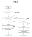
- the X-ray CT apparatus 1 of the present embodiment executes the image reconstruction process using the procedure shown in the flow chart of FIG. 6 . That is, the CPU of the system controller 401 reads out a program and data of the image reconstruction process shown in FIG. 6 from a storage unit and executes the process based on the program and data.
- the X-ray CT apparatus 1 performs settings such as scanning conditions and reconstruction conditions according to the operation by an operator (Step S 101 ).
- the system controller 401 displays the condition setting window 9 shown in FIG. 7 on the display device 405 .
- the scanogram image 91 and the cross-sectional model diagram 92 are displayed on the condition setting window 9 .
- the scanogram image 91 is acquired by a scanning process referred to as scanogram scanning in which an X-ray is irradiated while the X-ray tube 201 is being fixed to acquire an image in the body-axis direction after moving the bed table 3 .
- the condition setting area 96 for setting various scanning conditions and reconstruction conditions the normal reconstruction button 97 , the motion direction consideration reconstruction button 98 , the start scanning button 99 , the manual button 101 , the DB button 102 , the Raw button 103 , the Img button 104 , etc. are provided.
- the condition setting window 9 is an example, and the window configuration, buttons to be arranged, etc. are not limited to the example of FIG. 7 .
- the condition setting area 96 is an operation region for setting, for example, a scanning type, a scanning range, a site to be scanned, a posture, the number of scans, a scanning time, a scanning FOV, an image thickness, a reconstruction filter, a reconstruction FOV, and scanning conditions/reconstruction conditions such as a reconstruction method.
- a plurality of buttons for entering input screens for various conditions are arranged in the condition setting area 96 .
- the system controller 401 displays an input screen for a corresponding condition when a button in the condition setting area 96 is pressed down and receives an input of the condition. It may be configured so that a scanning range is set on the scanogram image 91 .
- the normal reconstruction button 97 is a button to be selected when performing a normal image reconstruction process that does not consider a motion direction.
- the motion direction consideration reconstruction button 98 is a button to be selected when performing an image reconstruction process that considers a motion direction.
- the manual button 101 , the DB button 102 , the Raw button 103 , and the Img button 104 are buttons that can be operated while the motion direction consideration reconstruction button 98 is being selected.
- the manual button 101 is to be operated when an operator inputs a motion direction and a motion center.
- the system controller 401 displays the motion direction manual setting window 9 a shown in FIG. 8 .
- the DB button 102 is selected when determining a motion direction by referring to a motion direction database (see FIG. 13 ; the second embodiment) to be described later.
- the Raw button 103 is operated to automatically detect a motion direction of a site to be scanned by analyzing projection data (the third embodiment).
- the Img button 104 is operated to automatically detect a motion direction of a site to be scanned by analyzing an image (the third embodiment).
- the start scanning button 99 is a button that can be selected after setting scanning conditions, a reconstruction process, etc.
- the system controller 401 starts scanning based on the set scanning conditions etc.
- Step S 101 scanning conditions and reconstruction conditions are set (Step S 101 ), the normal reconstruction button 97 is pressed down (Step S 102 : No), the start scanning button 99 is pressed down, and then the system controller 401 starts a normal scanning process (Step S 103 ).
- the system controller 401 controls the respective parts of the scanner gantry 2 and the bed table 3 according to the scanning conditions set in Step S 101 .
- an X-ray is irradiated while the bed table 3 is still to acquire projection data of a rotation of 360 degrees.
- the projection data of a rotation of 360 degrees is intermittently acquired in the same position by moving the bed table 3 by the set amount or without moving the bed table 3 .
- the system controller 401 transmits projection data acquired by scanning to the image processing device 403 .
- the image processing device 403 reconstructs a tomographic image of the object 6 based on the acquired projection data (Step S 104 ).
- Step S 102 when the motion direction consideration reconstruction button 98 and the manual button 101 are selected on the condition setting window 9 (Step S 102 : Yes), the system controller 401 displays the motion direction manual setting window 9 a shown in FIG. 8 on the display device 405 . An operator sets a motion direction and the motion center in the motion direction manual setting window 9 a (Step S 105 ).
- the image 107 according to the scanning range (scanning position) set in Step S 101 is displayed in the motion direction manual setting window 9 a .
- the motion direction line 97 and the motion center mark 94 are displayed in the image 107 .
- the measured image is desirably used as the image 107 .
- a model diagram etc. of a site to be scanned may be used.
- the serial images 106 for selecting the image 107 to set a motion direction and the object overall image 105 may be displayed. By moving the scanning position line 105 a on the object overall image 105 or selecting an image in a desired slice position of the serial images 106 , the motion direction setting image 107 to be displayed in the motion direction manual setting window 9 a can be selected.
- An angle of the motion direction line 93 can be changed by an operator. Also, a position of the motion center mark 94 can be changed by an operator. An operator changes an angle and a position of the motion direction line 93 and the motion center mark 94 using the input device 406 such as a mouse.
- the image processing device 403 acquires an set angle that the motion direction line 93 shows and a position designated by the motion center mark 94 . Then, the motion direction manual setting window 9 a is closed, and the condition setting window 9 reappears.
- Step S 106 the system controller 401 controls the respective parts of the scanner gantry 2 and the bed table 3 according to the scanning conditions set in Step S 101 .
- the system controller 401 transmits projection data acquired by scanning to the image processing device 403 .
- Step S 107 When the image processing device 403 acquires the projection data, a motion direction set in Step S 105 is considered to reconstruct a tomographic image of an object (Step S 107 ).
- the image processing device 403 sets projection data in a projection range of at least 180 degrees including a projection direction approximately corresponding to a motion direction set in Step S 105 , as the reconstruction data range 8 . Additionally, in a normal scan, a position (the start position 201 a ) of the X-ray tube 201 when scanning starts is set so that the position is not included in the reconstruction data range 8 . This is because a normal scan performing scanning by only one rotation results in that reconstruction is performed using temporally discontinuous projection data if the reconstruction data range 8 exceeds the start position 201 a.
- the image processing device 403 uses projection data of the reconstruction data range 8 to perform an image reconstruction process according to the reconstruction conditions.
- the image processing device 403 displays the generated image on the display device 405 , stores it in the storage unit of the system controller 401 , and then ends the present image reconstruction process.
- the X-ray CT apparatus 1 of the first embodiment reconstructs an image using projection data in a range of 180 degrees or more including a projection direction approximately corresponding to a motion direction of a site to be scanned.
- an image can be reconstructed using projection data in which influence in a motion direction of a scanning target site becomes the minimum between temporally distant projection data. Therefore, an image in which motion artifacts are reduced can be generated.
- the present invention can be applied also to a continuous dynamic scan in which the same body-axis direction position is continuously scanned while the bed table 3 is still to generate a different image from projection data continuous in the time-axis direction, a spiral scan (volume scan) in which X-rays are continuously irradiated while the bed table 3 is being moved using a multi-slice CT apparatus, etc.
- FIG. 9 is a diagram explaining a reconstruction data range in a continuous dynamic scan
- FIG. 10 is a diagram showing reconstruction data ranges in the continuous dynamic scan of FIG. 9 on projection data (a sinogram).
- motion artifacts can be reduced by setting projection data in a range of 180 degrees or more including a projection direction approximately corresponding to a motion direction of a site to be scanned as a reconstruction data range as described above. Additionally, there is no problem even if the reconstruction data range exceeds the starting point 201 a of X-ray irradiation in the continuous dynamic scan.
- the trajectories A and B in FIG. 9 are trajectories of the X-ray tube 201 corresponding to the respective reconstruction data ranges.
- projection data in a range of 180 degrees or more including a projection direction approximately corresponding to a motion direction of a site to be scanned”
- the trajectory B corresponding to the second reconstruction data range 8 B exceeds the starting point 201 a.
- the first reconstruction data range 8 A and the second reconstruction data range 8 B may be adopted similarly to FIG. 3 (a case of a normal scan). This is because a continuous dynamic scan continuously performs a plurality of scans for the same slice position to keep continuity of projection data between scans. In particular, this is effective in case of examining dynamics of a site to be scanned.
- FIG. 11 shows a reconstruction data range in case of performing a spiral scan using a multi-slice CT apparatus on projection data (a sinogram).
- a spiral scan X-rays are irradiated continuously while moving the bed table 3 .
- the image processing device 403 In case of performing a reconstruction process without considering a motion direction, the image processing device 403 conventionally collects projection data of at least 180 degrees by centering an angle at which a position of an image to be generated and a center slice correspond as shown in FIG. 11( a ) to reconstructs an image. Data in a proper position is collected for reconstruction by using projection data of a forward slice before the center angle and that of a backward slice after the center angle.
- the respective projection data 81 A to 81 I shown in the both-direction arrows in FIG. 11( a ) is used for reconstructing one tomographic image.
- the present invention uses projection data in a range of 180 degrees or more including a projection direction approximately corresponding to a motion direction of a site to be scanned for reconstruction from among the above projection data 81 A to 81 I as shown in FIG. 11( b ) . That is, the reconstruction data range indicates the ranges 82 A to 82 I shown in the both-direction arrows of solid lines in FIG. 11( b ) .
- the reconstruction data ranges 82 A to 82 C, 82 D to 82 F, and 82 G to 82 I become projection data acquired in the same projection angle range respectively.
- projection data in a range of 180 degrees or more including a projection direction approximately corresponding to a motion direction of a site to be scanned has two directions, more effects can be obtained when using projection data in which a trajectory of the X-ray tube 201 and a site to be scanned are closer.
- FIG. 12 is a diagram showing the functional configuration of the image processing device 403 in the second embodiment.
- the image processing device 403 of the second embodiment has the motion direction obtaining unit 403 a , the reconstruction data range calculation unit 403 b , the image reconstruction unit 403 c , and the motion direction database 403 d.
- the motion direction database 403 d is provided in addition to the functional configuration of the first embodiment shown in FIG. 2 .
- the motion direction database 403 d is held in the storage unit in advance.
- a motion direction is in the horizontal direction in a case where the site to be scanned is the heart; the posture is supine, and a motion direction is in the vertical direction in a case where the site to be scanned is the heart; the posture is recumbent.
- a motion direction is in the vertical direction in a case where the site to be scanned is the thorax (lungs); the posture is supine, and a motion direction is in the horizontal direction in a case where the site to be scanned is the thorax (lungs); the posture is recumbent.
- the motion direction obtaining unit 403 a of the image processing device 403 obtains a motion direction according to the site to be scanned and the posture by referring to the motion direction database 403 d . Then, a range of projection data (reconstruction data range) to be used for reconstructing an image is calculated based on the obtained motion information. Additionally, the site to be scanned and the posture have been set as scanning conditions.
- the X-ray CT apparatus 1 performs setting for scanning conditions and reconstruction conditions according to the operation by an operator (Step S 201 ). Setting the scanning conditions and reconstruction conditions is performed on the condition setting window 9 shown in FIG. 7 similarly to Step S 101 of FIG. 6 .
- Step S 202 No to Step S 204
- Step S 102 No to Step S 104 of the first embodiment
- Step S 201 when scanning conditions and reconstruction conditions are set (Step S 201 ); the motion direction considering reconstruction button 98 is selected; and additionally the DB button 102 is selected (Step S 202 : Yes), the system controller 401 loads the motion direction database 403 d shown in FIG. 13 to determine a motion direction in accordance with a site to be scanned and a posture (Step S 205 ). The system controller 401 transmits the determined motion direction to the image processing device 403 .
- Step S 206 the system controller 401 controls the respective parts of the scanner gantry 2 and the bed table 3 according to the scanning conditions set in Step S 201 .
- the system controller 401 transmits projection data acquired by scanning to the image processing device 403 .
- the image processing device 403 After acquiring the projection data, the image processing device 403 considers the motion direction determined in Step S 205 to reconstruct a tomographic image of an object (Step S 207 ).
- the image processing device 403 reconstructs an image by setting projection data in a projection range of at least 180 degrees or more including a projection direction approximately corresponding to a motion direction as the reconstruction data range 8 .
- the image processing device 403 displays an image reconstructed in Steps S 204 and S 207 on the display device 405 , stores it in the storage unit of the system controller 401 , and then ends the present image reconstruction process.
- the process of the second embodiment can be applied to any of a normal scan, a continuous dynamic scan, and a volume scan described in the first embodiment.
- the X-ray CT apparatus 1 stores the motion direction database 403 d in advance, which can obtain a motion direction according to the site to be scanned and the posture from the motion direction database 403 d . Therefore, an operator does not need to set a motion direction manually, which results in that image reconstruction considering a motion direction can be performed with an easier operation.
- FIG. 15 is a diagram showing the functional configuration of the image processing device 403 of the third embodiment.
- the image processing device 403 of the third embodiment has the motion direction obtaining unit 403 a , the motion detecting unit 403 e , the reconstruction data range calculation unit 403 b , and the image reconstruction unit 403 c.
- the motion detecting unit 403 e is provided in addition to the functional configuration of the first embodiment shown in FIG. 2 .
- the motion detecting unit 403 e detects a motion direction of a site to be scanned. For example, the following two methods of detecting a motion direction can be considered.
- the motion direction obtaining unit 403 a of the image processing device 403 obtains a motion direction calculated by the motion detecting unit 403 e and transmits it to the reconstruction data range calculation unit 403 b .
- the reconstruction data range calculation unit 403 b calculates a range of projection data (reconstruction data range) to be used for reconstructing an image based on the obtained motion direction.
- the X-ray CT apparatus 1 performs setting for scanning conditions and reconstruction conditions according to the operation by an operator (Step S 301 ). Setting the scanning conditions and reconstruction conditions is performed on the condition setting window 9 ( FIG. 7 ) similarly to Step S 101 of FIG. 6 .
- Step S 302 No to Step S 304
- Step S 102 No to Step S 104 of the first embodiment
- the system controller 401 displays the motion direction automatic setting window 9 c shown in FIG. 17 on the display device 405 .
- An operator sets a target area where motion information is detected using the motion direction automatic setting window 9 c (Step S 305 ).
- the motion direction automatic setting window 9 c displays the image 107 according to the scanning range (scanning position) set in Step S 301 .
- the target area setting frame 65 is displayed in the image 107 .
- the size and position of the target area setting frame 65 can be changed by an operator's operation.
- target area setting frame 65 is not limited to an oval shape as shown in FIG. 17 but may be a rectangle, a circle, or the other arbitrary shapes.
- An operator changes the position and size of the target area setting frame 65 using the input device 406 such as a mouse to select a desired site.
- the selected site is designated as an analysis target for motion information.
- the image processing device 403 obtains a position and size of the set target area 65 , closes the motion direction automatic setting window 9 c , and then goes back to the condition setting window 9 .
- the image processing device 403 checks a set motion detection algorism (motion detection method), and the process proceeds according to the set algorism.
- the motion detection algorism (the above motion detection method of (a)) is executed based on projection data analysis (Step S 306 : PROJECTION DATA).
- the motion detection algorism (the above motion detection method of (b)) is executed based on image analysis (Step S 306 : IMAGE).
- a scanning process is first performed (Steps S 307 and S 310 ).
- the scanning process starts when the start scanning button 99 on the condition setting window 9 is pressed down.
- the scanning process is similar to the scanning process etc. in Step S 103 of the first embodiment.
- the image processing device 403 acquires projection data to calculate a motion direction based on the projection data (Step S 308 ).
- a method to calculate a motion direction from the projection data for example, there is a method to compare opposite data.
- the opposite data is projection data whose projection direction is inverted by 180 degrees.
- the image processing device 403 obtains a difference of the opposite data and calculates a motion direction based on a size of the difference.
- FIG. 18( a ) is a diagram showing the arrangement of the X-ray tubes 201 in case of opposite data whose direction corresponds to the motion direction 71 .
- a difference by motion becomes small between the opposite data in case of the opposite data whose projection direction corresponds to a motion direction.
- FIG. 18( b ) a difference by motion becomes large between the opposite data in case of the projection data whose direction is vertical to the motion direction 71 .
- the image processing device 403 obtains differences at various angles to calculate an angle of opposite data with the minimal difference as a motion direction.
- a target area in a case where a target area is set (see FIG. 17 ), it may be configured so that a difference of opposite data is calculated by setting the target area only as a calculation target. Because only the target area is calculated, the range is narrowed down, which can perform high-speed processing.
- the image processing device 403 reconstructs an image by setting projection data in a projection range of at least 180 degrees or more including a projection direction approximately corresponding to a motion direction calculated in Step S 308 as the reconstruction data range 8 (Step S 309 ).
- the image processing device 403 When the Img button 104 is selected on the condition setting window 9 , the image processing device 403 generates a plurality of analysis images based on the acquired projection data (Step S 311 ).
- FIG. 19 is a diagram explaining an analysis image.
- a range of at least 180 degrees to be used for reconstruction is cut out of projection data by shifting the range gradually.
- An image reconstructed using projection data of the range 83 A shown in FIG. 19( a ) is the analysis image 84 A of FIG. 19( b ) .
- An image reconstructed using projection data of the range 83 B slightly shifted from the range 83 A is the analysis image 84 B of FIG. 19( b ) .
- the analysis images 84 C to 84 F are generated by gradually shifting a projection data range to be used.
- the range 83 D is the opposite data of the range 83 A
- the range 83 E is the opposite data of the range 83 B
- the range 83 F is the opposite data of the range 83 C.
- the image processing device 403 obtains a difference between the analysis images 84 A and 84 D reconstructed by opposite data. Similarly, a difference between the analysis images 84 B and 84 E and a difference between the analysis images 84 C and 84 F are obtained respectively. Then, a projection direction of an analysis image with the minimal difference at an opposite angle is set as a motion direction (Step S 312 ).
- only the target area may be set as a target for difference calculation. That is, the image processing device 403 calculates a difference of opposite images only for pixels in the target area. Because the calculation range is narrowed down, high-speed processing can be performed.
- the image processing device 403 reconstructs an image by setting projection data in a projection range of at least 180 degrees or more including a projection direction approximately corresponding to a motion direction calculated in Step S 312 as the reconstruction data range 8 (Step S 313 ).
- the image processing device 403 displays images reconstructed in Steps S 304 , S 309 , and S 313 on the display device 405 , stores them in the storage unit of the system controller 401 , and then ends the present image reconstruction process.
- the process of the third embodiment can be applied to any of a normal scan, a continuous dynamic scan, and a volume scan described in the first embodiment.
- the X-ray CT apparatus 1 can detect a motion direction based on projection data obtained by scanning or a reconstructed image. Therefore, an operator does not need to set a motion direction manually. Also, because a motion of a site to be scanned is analyzed based on scanned projection data of an object itself, a motion direction can be obtained accurately.
- the fourth embodiment is an embodiment assuming electrocardiographic synchronous scanning that is generally performed for heart scanning and the like.
- electrocardiographic synchronous scanning the pulse of an object is measured by the electrocardiograph 7 etc. during scanning.
- a spiral scan is performed while a multiple-scan overlap is being performed for a site to be scanned.
- projection data of 180 degrees is calculated by combining with the projection data acquired in a certain cardiac phase section (a still phase) where a motion amount is the minimum to reconstruct an image.
- a motion amount and a motion direction are considered to calculate a reconstruction data range in this electrocardiographic synchronous scanning.
- FIG. 20 is a diagram showing the functional configuration of the image processing device 403 in the fourth embodiment.
- the image processing device 403 of the fourth embodiment has the motion direction obtaining unit 403 a , the motion amount calculation unit 403 f , the reconstruction data range calculation unit 403 b , and the image reconstruction unit 403 c . That is, the fourth embodiment has the motion amount calculation unit 403 f in addition to the functional configuration of the first embodiment shown in FIG. 2 .
- the motion amount calculation unit 403 f calculates a motion amount of a site to be scanned.
- the motion amount for example, can be calculated by comparing tomographic images whose phases are the same and scanning positions are different. Additionally, the calculation method of a motion amount is not limited to this, and the motion amount may be calculated by the other methods.
- the graph g 1 of FIG. 21 is a graph showing the transition of the motion amount in each projection direction (X-ray irradiation angle).
- the vertical axis is a projection direction (an X-ray irradiation angle), and the horizontal axis is a motion amount.
- the image processing device 403 reconstructs an image using projection data in the range 8 C of at least 180 degrees by setting the projection data position a at which a motion amount is the minimum as the center.
- the image processing device 403 calculates a reconstruction data range by considering a motion amount and a motion direction.
- the reconstruction data range calculation unit 403 b generates a motion-direction weight considering influence by a motion direction. Then, a reconstruction data range is adjusted by multiplying the motion direction weight by a motion amount.
- the graph g 2 of FIG. 21 is a graph showing the transition of the motion-direction weight in the respective projection directions (X-ray irradiation angles).
- the vertical axis is a projection direction (an X-ray irradiation angle), and the horizontal axis is a motion-direction weight.
- a motion-direction weight is a projection direction corresponding to a motion direction and is generated so that a value of “a motion amount ⁇ a motion-direction weight” becomes small.
- the graph g 3 of FIG. 21 is a graph showing the transition of a motion amount ⁇ a motion-direction weight in the respective projection directions (X-ray irradiation angles).
- the vertical axis is a projection direction (an X-ray irradiation angle), and the horizontal axis shows a value in which a motion amount was multiplied by a motion-direction weight.
- the range 8D where a value of a motion amount ⁇ a motion-direction weight becomes the minimum is set as a reconstruction data range.
- the range 8D where a value of a motion amount ⁇ a motion-direction weight becomes the minimum may be set as an angle range of 180 degrees centering on a projection data position where a value of a motion amount ⁇ a motion-direction weight becomes the minimum or may be set as an angle range of 180 degrees where the total of values of motion amounts ⁇ motion-direction weights becomes the minimum.
- a motion direction may be set as a motion direction manually set by an operator as described in the first embodiment. Also, as described in the second embodiment, a motion direction may be determined by referring to the motion direction database 403 d . Alternatively, as described in the third embodiment, a motion direction may be calculated by the image processing device 403 based on projection data etc.
- the image reconstruction unit 403 c reconstructs an image using the projection data of the reconstruction data range 8 D.
- a motion amount and a motion direction of a target site are considered to calculate a reconstruction data range. Therefore, an image can be reconstructed using projection data with a small motion amount and small influence by a motion direction. Hence, motion artifacts can be further reduced.
- the first to fourth embodiments were described on the presumption that motion directions in all the positions in a scanning range were the same. However, the motion directions are not always the same in the entire scanning range. For example, there is a case where a different motion direction is shown depending on the slice position. Also, there is a case where a different motion direction is shown even in the same slice position depending on the site.
- FIG. 22 is the motion direction automatic setting window 9 d in case of automatically setting the respective motion directions in ranges different in the slice direction.
- the motion direction automatic setting window 9 d displays the object overall image 105 , the serial images 106 , and the tomographic images 107 a and 107 b . Then, the range setting GUIs 105 b and 105 c to set a slice direction range are displayed in the object overall image 105 . A plurality of the range setting GUIs 105 b and 105 c can be displayed. Although two of the range setting GUIs 105 b and 105 c are provided in an example of FIG. 22 , three or more of them may be provided. In the following description, a slice direction range to be set in the range setting GUI 105 b is referred to as a first range.
- a slice direction range to be set in the range setting GUI 105 c is referred to as a second range.
- the lengths and positions of the arrows of the range setting GUIs 105 b and 105 c can be changed by operations with a mouse etc.
- the GUI 106 a displayed near the serial images shows image positions corresponding to the respective slice direction ranges set by the range setting GUIs 105 b and 105 c.
- the tomographic images 107 a and 107 b are tomographic images in a representative slice position in a plurality of specified slice direction ranges. If the display window becomes narrow, it may be configured so that a tomographic image can be operated with it displayed in the forefront when any of the tomographic images is designated with a mouse etc. by partially overlapping the respective tomographic images 107 a and 107 b as shown in FIG. 22 .
- the image processing device 403 receives the settings for the target area 65 of a motion direction for the tomographic image 107 displayed in the forefront. Also, similarly to the third embodiment, a motion direction is calculated for each slice direction range.
- a plurality of motion directions may be set in one image.
- the tomographic image 107 d is divided into two regions by the dividing line 60 .
- One region divided by the dividing line is referred to as the first region 60 a
- the other region is referred to as the second region 60 b .
- the division number may not be limited to two, but also may be equal to or more than three.
- the motion center marks 93 a and 93 b as well as the motion direction lines 94 a and 94 b are displayed in the respective regions.
- An operator changes positions of the motion center marks 93 a and 93 b as well as angles of the motion direction lines 94 a and 94 b .
- motion center points and motion directions can be set for the respective regions.
- a motion direction can be automatically set in the respective division regions 60 a and 60 b .
- the image processing device 403 has the motion detecting unit 403 e as shown in the third embodiment.
- the motion detecting unit 403 e calculates a motion direction in each division region based on projection data or an image.
- the image processing device 403 calculates a range of projection data (reconstruction data range) to be used for reconstructing an image based on a motion direction of each division region calculated by the motion detecting unit 403 e .
- the reconstruction data range is set as a projection range of at least 180 degrees or more including a projection direction approximately corresponding to the motion direction similarly to the first to third embodiments.
- the image processing device 403 reconstructs an image using projection data in a reconstruction data range in each division region. Interpolation calculation is performed so that pixels on the boundary between image division regions are connected smoothly to generate an image.
- the X-ray CT apparatus 1 of the fifth embodiment can set a plurality of motion directions in a scanning range and set a reconstruction data range according to each motion direction.
- an image can be generated using data in a reconstruction data range where motion influence becomes the minimum, for example, even in a case where a different motion direction is shown depending on the slice position and a case where a different motion direction is shown for each different site in the same slice position. This can reduce motion artifacts.
- the sixth embodiment is an embodiment presuming a half scan.
- the half scan is a scanning method that acquires projection data by irradiating an X-ray only in a projection direction of a half rotation (a 180-degree range) and does not acquire projection data by stopping X-ray irradiation in a projection direction of the other half rotation.
- FIG. 24 is a diagram showing the functional configuration of the image processing device 403 in the sixth embodiment.
- the image processing device 403 in the sixth embodiment has the motion direction obtaining unit 403 a , the reconstruction data range calculation unit 403 b , the X-ray control unit 403 g , and the image reconstruction unit 403 c.
- the X-ray control unit 403 g is included in addition to the functional configuration of the first embodiment shown in FIG. 2 .
- the X-ray control unit 403 g controls so that the X-ray tube 201 irradiates an X-ray at an X-ray irradiation angle equivalent to a reconstruction data range calculated by the reconstruction data range calculation unit 403 b . Additionally, the X-ray control unit 403 g controls not only an X-ray irradiation range but also an X-ray tube current, an X-ray tube voltage, etc. The X-ray tube current and the X-ray tube voltage are determined based on scanning conditions and reconstruction conditions.
- FIG. 25 shows a relationship between the motion direction 71 and the X-ray irradiation start point 55 as well as the X-ray irradiation end point 56 that correspond to a reconstruction data range (the trajectory A).
- the image processing device 403 obtains a motion direction of a site to be scanned and then calculates the reconstruction data range 8 according to the motion direction.
- the reconstruction data range 8 is a range of at least 180 degrees or more including a projection direction (an X-ray irradiation angle) approximately corresponding to the motion direction.
- the motion direction may be set manually by an operator similarly to any of the methods of the first to third embodiments, may be determined by referring to the motion direction database 403 d , or may be determined based on differences of the opposite projection data and the images by the motion detecting unit 403 e.
- the image processing device 403 transmits the calculated reconstruction data range 8 to the X-ray control unit 403 g .
- the X-ray control unit 403 g controls an X-ray irradiation timing so that the ends of the trajectory A corresponding to the reconstruction data range 8 become the X-ray irradiation start point 55 and the X-ray irradiation end point 56 as shown in FIG. 25 .
- the image processing device 403 acquires projection data in the range of 180 degrees from the X-ray irradiation start point 55 to the X-ray irradiation end point 56 while the bed table 3 is still in a predetermined slice position. Next, by moving the bed table 3 by a set amount, the projection data is acquired in the range of 180 degrees from the X-ray irradiation start point 55 to the X-ray irradiation end point 56 . Alternatively, the projection data is acquired in the range of 180 degrees from the X-ray irradiation start point 55 to the X-ray irradiation end point 56 intermittently without moving the bed table 3 in the same position. By repeating such operations, projection data shown in FIG. 26 is acquired.
- FIG. 26 shows projection data acquired when a range equivalent to the reconstruction data range 8 is set as an X-ray irradiation region.
- the projection data of the scan SC- 1 in the first rotation, SC- 2 in the second rotation, SC- 3 in the third rotation, . . . is acquired in each slice position.
- an X-ray is irradiated to each of the scans SC- 1 , SC- 2 , and SC- 3 in a range of the trajectory A. That is, the projection data is measured in ranges corresponding to the reconstruction data ranges 8 A- 1 , 8 A- 2 , and 8 A- 3 , and the other range is in a state where there is no data.
- the image processing device 403 reconstructs an image using data in the reconstruction data ranges 8 A- 1 , 8 A- 2 , and 8 A- 3 .
- the X-ray CT apparatus 1 of the sixth embodiment controls an X-ray irradiation range in association with the reconstruction data range 8 determined based on a motion direction. Therefore, a half scan can be performed at an optimal X-ray irradiation angle with low motion influence. Therefore, while motion artifacts are reduced, an exposure dose can also be reduced.
- X-ray irradiation control described in the sixth embodiment may be applied to, for example, a prospective ECG scan to be performed in heart scanning and the like.
- the prospective ECG scan is a scanning method to control an X-ray irradiation amount based on electrocardiac information measured by an electrocardiograph when a site to be scanned with a motion such as the heart is scanned.
- an X-ray irradiation amount is increased in a phase where a motion amount of a site to be scanned becomes the minimum (static phase) and is reduced to the minimum required for reconstructing an image in the other phase.
- a motion amount is calculated at each projection angle (phase) as shown in the graph g 3 of FIG. 21 , and the reconstruction data range 8 D is further determined by considering the motion amount.
- the reconstruction data range 8 D is further determined by considering the motion amount.
- the present invention can be applied even in a prospective ECG scan. Therefore, while an exposure dose is reduced, motion artifacts can be reduced.
- the X-ray CT apparatus 1 of the present invention determines a range of projection data to be used for image reconstruction (reconstruction data range) based on a motion direction of a site to be scanned and generates an image using the data in the reconstruction data range. Hence, when scanning a site to be scanned including a periodic motion, an image with low motion influence can be generated.
- X-ray CT apparatus 1 : X-ray CT apparatus, 2 : scanner gantry, 201 : X-ray tube, 202 : measurement controller, 205 : X-ray detector, 210 : rotary driving device, 3 : bed table, 4 : operation console, 401 : system controller, 403 : image processing device, 403 a : motion direction obtaining unit, 403 b : reconstruction data range calculation unit, 403 c : image reconstruction unit, 403 d : motion direction database, 403 e : motion detecting unit, 403 f : motion amount calculation unit, 403 g : X-ray control unit 405 : display device, 406 : input device, 6 : object, 7 : electrocardiograph, 8 and 8 A to 8 D: reconstruction data range, A and B: trajectory of the X-ray tube 201 , 51 first projection direction (X-ray irradiation angle), 52 : second projection direction (X-ray irradiation angle), 55 :
Abstract
Description
Claims (16)
Applications Claiming Priority (3)
| Application Number | Priority Date | Filing Date | Title |
|---|---|---|---|
| JP2013-032438 | 2013-02-21 | ||
| JP2013032438 | 2013-02-21 | ||
| PCT/JP2014/053677 WO2014129428A1 (en) | 2013-02-21 | 2014-02-18 | X-ray ct device and image reconstruction method |
Publications (2)
| Publication Number | Publication Date |
|---|---|
| US20150356756A1 US20150356756A1 (en) | 2015-12-10 |
| US9542762B2 true US9542762B2 (en) | 2017-01-10 |
Family
ID=51391220
Family Applications (1)
| Application Number | Title | Priority Date | Filing Date |
|---|---|---|---|
| US14/763,329 Active US9542762B2 (en) | 2013-02-21 | 2014-02-18 | X-ray CT apparatus and image reconstruction method |
Country Status (4)
| Country | Link |
|---|---|
| US (1) | US9542762B2 (en) |
| JP (1) | JP6233980B2 (en) |
| CN (1) | CN104955396B (en) |
| WO (1) | WO2014129428A1 (en) |
Cited By (3)
| Publication number | Priority date | Publication date | Assignee | Title |
|---|---|---|---|---|
| US20160110864A1 (en) * | 2014-10-21 | 2016-04-21 | Shenyang Neusoft Medical Systems Co., Ltd. | Calculating the motion vector field for a reconstructed ct scan image |
| US10445886B2 (en) * | 2017-05-30 | 2019-10-15 | General Electric Company | Motion-gated medical imaging |
| US10568599B2 (en) * | 2014-09-09 | 2020-02-25 | General Electric Company | Multiple frame acquisition for exposure control in X-ray medical imagers |
Families Citing this family (9)
| Publication number | Priority date | Publication date | Assignee | Title |
|---|---|---|---|---|
| US10025479B2 (en) * | 2013-09-25 | 2018-07-17 | Terarecon, Inc. | Advanced medical image processing wizard |
| JP6381198B2 (en) * | 2013-11-08 | 2018-08-29 | キヤノン株式会社 | Control device, control method and program |
| KR101579111B1 (en) | 2014-02-24 | 2015-12-21 | 삼성전자주식회사 | Method and apparatus for diagnosing through image and recording medium thereof |
| KR101964844B1 (en) * | 2016-07-22 | 2019-04-03 | 주식회사 바텍 | Apparatus and Method for CT Image Reconstruction Based on Motion Compensation |
| EP3272288B1 (en) * | 2016-07-22 | 2019-03-20 | Vatech Co. Ltd. | Apparatus and method for ct data reconstruction based on motion compensation |
| JP6608111B2 (en) * | 2016-09-28 | 2019-11-20 | 富士フイルム株式会社 | MEDICAL IMAGE STORAGE / REPRODUCING DEVICE AND METHOD, AND PROGRAM |
| US10977840B2 (en) * | 2018-08-21 | 2021-04-13 | Shanghai United Imaging Healthcare Co., Ltd. | Systems and methods for iterative reconstruction |
| US11298088B2 (en) * | 2020-03-31 | 2022-04-12 | Varian Medical Systems International Ag | Cone-beam computed tomography with continuous kV beam acquisition |
| CN112669405B (en) * | 2020-12-30 | 2023-01-20 | 上海联影医疗科技股份有限公司 | Image reconstruction method, system, readable storage medium and device |
Citations (18)
| Publication number | Priority date | Publication date | Assignee | Title |
|---|---|---|---|---|
| US6894494B2 (en) * | 2002-11-25 | 2005-05-17 | Her Majesty The Queen In Right Of Canada, As Represented By The Minister Of National Defence Of Her Majesty's Canadian Government | Method and device for correcting organ motion artifacts in MRI systems |
| US6934357B2 (en) * | 2002-07-23 | 2005-08-23 | Ge Medical Systems Global Technology Company Llc | Methods and apparatus for motion compensation in image reconstruction |
| US7494277B2 (en) * | 2006-05-31 | 2009-02-24 | Palodex Group Oy | Method and apparatus for medical X-radiography |
| US7558439B2 (en) * | 2002-07-10 | 2009-07-07 | Koninklijke Philips Electronics N.V. | Motion artifact correction of tomographical images |
| US20100111393A1 (en) * | 2008-09-30 | 2010-05-06 | Kabushiki Kaisha Toshiba | X-ray ct apparatus and control method of x-ray ct apparatus |
| US7787927B2 (en) * | 2003-06-20 | 2010-08-31 | Merge Cad Inc. | System and method for adaptive medical image registration |
| US20110052027A1 (en) | 2009-08-31 | 2011-03-03 | Yasuhiro Noshi | Image reconstructing apparatus, x-ray computed tomography apparatus, and image reconstructing method |
| US20110142314A1 (en) | 2009-12-15 | 2011-06-16 | Jiang Hsieh | System and method of increasing temporal resolution of an x-ray image |
| US20110293155A1 (en) | 2010-05-25 | 2011-12-01 | Toshiba Medical Systems Corporation | Automatic motion map generation in helical ct |
| JP2012019892A (en) | 2010-07-13 | 2012-02-02 | Toshiba Corp | Radiation computed tomography imaging apparatus, medical image generator, and breathing phase measuring apparatus |
| US20120207355A1 (en) * | 2009-11-04 | 2012-08-16 | Hitachi Medical Corporation | X-ray ct apparatus and image display method of x-ray ct apparatus |
| US8437524B2 (en) * | 2007-01-08 | 2013-05-07 | Koninklijke Philips Electronics N. V. | Imaging system for imaging a region of interest in different phases |
| US20130182935A1 (en) * | 2011-07-19 | 2013-07-18 | Toshiba Medical Systems Corporation | Apparatus and method for tracking contour of moving object, and apparatus and method for analyzing myocardial motion |
| US8600132B2 (en) * | 2011-05-03 | 2013-12-03 | General Electric Company | Method and apparatus for motion correcting medical images |
| US8761478B2 (en) * | 2009-12-15 | 2014-06-24 | General Electric Company | System and method for tomographic data acquisition and image reconstruction |
| US8923590B2 (en) * | 2011-01-20 | 2014-12-30 | Siemens Aktiengesellschaft | Method and system for 3D cardiac motion estimation from single scan of C-arm angiography |
| US9060733B2 (en) * | 2011-09-28 | 2015-06-23 | Siemens Aktiengesellschaft | Method, computer system and CT system for determining a motion field and for motion-compensated reconstruction using said motion field |
| US9117289B2 (en) * | 2011-11-11 | 2015-08-25 | Konica Minolta, Inc. | Medical imaging system, medical image processing apparatus, and computer-readable medium |
Family Cites Families (5)
| Publication number | Priority date | Publication date | Assignee | Title |
|---|---|---|---|---|
| JP2005137390A (en) * | 2003-11-04 | 2005-06-02 | Ge Medical Systems Global Technology Co Llc | Ct image creating method and x-ray ct equipment |
| JP2007521906A (en) * | 2004-02-13 | 2007-08-09 | コーニンクレッカ フィリップス エレクトロニクス エヌ ヴィ | Motion artifact compensation |
| JP4414420B2 (en) * | 2006-10-27 | 2010-02-10 | ジーイー・メディカル・システムズ・グローバル・テクノロジー・カンパニー・エルエルシー | X-ray tomography apparatus and artifact reduction method |
| CN102144927B (en) * | 2010-02-10 | 2012-12-12 | 清华大学 | Motion-compensation-based computed tomography (CT) equipment and method |
| CN102258383B (en) * | 2010-05-25 | 2013-03-20 | 株式会社东芝 | X ray computer tomography device and image processing method |
-
2014
- 2014-02-18 WO PCT/JP2014/053677 patent/WO2014129428A1/en active Application Filing
- 2014-02-18 JP JP2015501442A patent/JP6233980B2/en active Active
- 2014-02-18 CN CN201480005512.5A patent/CN104955396B/en active Active
- 2014-02-18 US US14/763,329 patent/US9542762B2/en active Active
Patent Citations (21)
| Publication number | Priority date | Publication date | Assignee | Title |
|---|---|---|---|---|
| US7558439B2 (en) * | 2002-07-10 | 2009-07-07 | Koninklijke Philips Electronics N.V. | Motion artifact correction of tomographical images |
| US6934357B2 (en) * | 2002-07-23 | 2005-08-23 | Ge Medical Systems Global Technology Company Llc | Methods and apparatus for motion compensation in image reconstruction |
| US6894494B2 (en) * | 2002-11-25 | 2005-05-17 | Her Majesty The Queen In Right Of Canada, As Represented By The Minister Of National Defence Of Her Majesty's Canadian Government | Method and device for correcting organ motion artifacts in MRI systems |
| US7787927B2 (en) * | 2003-06-20 | 2010-08-31 | Merge Cad Inc. | System and method for adaptive medical image registration |
| US7494277B2 (en) * | 2006-05-31 | 2009-02-24 | Palodex Group Oy | Method and apparatus for medical X-radiography |
| US8437524B2 (en) * | 2007-01-08 | 2013-05-07 | Koninklijke Philips Electronics N. V. | Imaging system for imaging a region of interest in different phases |
| US20100111393A1 (en) * | 2008-09-30 | 2010-05-06 | Kabushiki Kaisha Toshiba | X-ray ct apparatus and control method of x-ray ct apparatus |
| US20110052027A1 (en) | 2009-08-31 | 2011-03-03 | Yasuhiro Noshi | Image reconstructing apparatus, x-ray computed tomography apparatus, and image reconstructing method |
| JP2011050509A (en) | 2009-08-31 | 2011-03-17 | Toshiba Corp | Image reconstructing apparatus and x-ray computer tomography apparatus |
| US20120207355A1 (en) * | 2009-11-04 | 2012-08-16 | Hitachi Medical Corporation | X-ray ct apparatus and image display method of x-ray ct apparatus |
| US20110142314A1 (en) | 2009-12-15 | 2011-06-16 | Jiang Hsieh | System and method of increasing temporal resolution of an x-ray image |
| JP2011125700A (en) | 2009-12-15 | 2011-06-30 | General Electric Co <Ge> | System and method of increasing temporal resolution of x-ray image |
| US8761478B2 (en) * | 2009-12-15 | 2014-06-24 | General Electric Company | System and method for tomographic data acquisition and image reconstruction |
| US20110293155A1 (en) | 2010-05-25 | 2011-12-01 | Toshiba Medical Systems Corporation | Automatic motion map generation in helical ct |
| JP2011245281A (en) | 2010-05-25 | 2011-12-08 | Toshiba Corp | X-ray computed tomography device and image processing method |
| JP2012019892A (en) | 2010-07-13 | 2012-02-02 | Toshiba Corp | Radiation computed tomography imaging apparatus, medical image generator, and breathing phase measuring apparatus |
| US8923590B2 (en) * | 2011-01-20 | 2014-12-30 | Siemens Aktiengesellschaft | Method and system for 3D cardiac motion estimation from single scan of C-arm angiography |
| US8600132B2 (en) * | 2011-05-03 | 2013-12-03 | General Electric Company | Method and apparatus for motion correcting medical images |
| US20130182935A1 (en) * | 2011-07-19 | 2013-07-18 | Toshiba Medical Systems Corporation | Apparatus and method for tracking contour of moving object, and apparatus and method for analyzing myocardial motion |
| US9060733B2 (en) * | 2011-09-28 | 2015-06-23 | Siemens Aktiengesellschaft | Method, computer system and CT system for determining a motion field and for motion-compensated reconstruction using said motion field |
| US9117289B2 (en) * | 2011-11-11 | 2015-08-25 | Konica Minolta, Inc. | Medical imaging system, medical image processing apparatus, and computer-readable medium |
Non-Patent Citations (8)
Cited By (4)
| Publication number | Priority date | Publication date | Assignee | Title |
|---|---|---|---|---|
| US10568599B2 (en) * | 2014-09-09 | 2020-02-25 | General Electric Company | Multiple frame acquisition for exposure control in X-ray medical imagers |
| US20160110864A1 (en) * | 2014-10-21 | 2016-04-21 | Shenyang Neusoft Medical Systems Co., Ltd. | Calculating the motion vector field for a reconstructed ct scan image |
| US9636074B2 (en) * | 2014-10-21 | 2017-05-02 | Shenyang Neusoft Medical Systems Co., Ltd. | Calculating the motion vector field for a reconstructed CT scan image |
| US10445886B2 (en) * | 2017-05-30 | 2019-10-15 | General Electric Company | Motion-gated medical imaging |
Also Published As
| Publication number | Publication date |
|---|---|
| JPWO2014129428A1 (en) | 2017-02-02 |
| WO2014129428A1 (en) | 2014-08-28 |
| JP6233980B2 (en) | 2017-11-22 |
| CN104955396A (en) | 2015-09-30 |
| CN104955396B (en) | 2017-11-03 |
| US20150356756A1 (en) | 2015-12-10 |
Similar Documents
| Publication | Publication Date | Title |
|---|---|---|
| US9542762B2 (en) | X-ray CT apparatus and image reconstruction method | |
| US9715745B2 (en) | X-ray CT apparatus and image reconstruction method | |
| US10433803B2 (en) | X-ray CT apparatus and image reconstruction method | |
| JP5248031B2 (en) | X-ray CT system | |
| EP1834585B1 (en) | An X-ray CT apparatus, a method for changing the helical pitch, an image reconstruction processing apparatus, an image reconstruction processing method, and an image reconstruction processing program | |
| US7668286B2 (en) | X-ray CT apparatus | |
| US8351565B2 (en) | X-ray CT apparatus | |
| US20030076919A1 (en) | X-ray computed tomography apparatus | |
| JP6027546B2 (en) | MEDICAL IMAGE DIAGNOSIS DEVICE AND PHASE DETERMINING METHOD USING MEDICAL IMAGE DIAGNOSIS DEVICE | |
| US9974495B2 (en) | X-ray CT apparatus, image processing device, and image reconstruction method | |
| WO2015107963A1 (en) | X-ray ct device and contrast imaging method | |
| JP2007175258A (en) | Tomographic x-ray equipment and x-ray tomographic method | |
| US9129389B2 (en) | X-ray CT apparatus and image correction method | |
| US9326746B2 (en) | X-ray CT apparatus | |
| US20180214110A1 (en) | Medical image-processing apparatus, x-ray ct apparatus, and medical image-processing method | |
| WO2013187461A1 (en) | X-ray ct apparatus and image reconstruction method | |
| JP5203750B2 (en) | ECG synchronous scanning method and X-ray computed tomography apparatus | |
| JP6286220B2 (en) | X-ray CT system | |
| WO2014188936A1 (en) | X-ray ct device and imaging method | |
| JP5931642B2 (en) | X-ray CT system | |
| JP2008011895A (en) | X-ray ct apparatus |
Legal Events
| Date | Code | Title | Description |
|---|---|---|---|
| AS | Assignment |
Owner name: HITACHI MEDICAL CORPORATION, JAPAN Free format text: ASSIGNMENT OF ASSIGNORS INTEREST;ASSIGNORS:OKAMOTO, SHUICHI;KOKUBUN, HIROTO;TERAMOTO, FUYUHIKO;REEL/FRAME:036172/0594 Effective date: 20150525 |
|
| AS | Assignment |
Owner name: HITACHI, LTD., JAPAN Free format text: MERGER;ASSIGNOR:HITACHI MEDICAL CORPORATION;REEL/FRAME:040019/0013 Effective date: 20160401 |
|
| STCF | Information on status: patent grant |
Free format text: PATENTED CASE |
|
| MAFP | Maintenance fee payment |
Free format text: PAYMENT OF MAINTENANCE FEE, 4TH YEAR, LARGE ENTITY (ORIGINAL EVENT CODE: M1551); ENTITY STATUS OF PATENT OWNER: LARGE ENTITY Year of fee payment: 4 |
|
| AS | Assignment |
Owner name: FUJIFILM HEALTHCARE CORPORATION, JAPAN Free format text: ASSIGNMENT OF ASSIGNORS INTEREST;ASSIGNOR:HITACHI, LTD.;REEL/FRAME:058026/0559 Effective date: 20211013 |
|
| AS | Assignment |
Owner name: FUJIFILM HEALTHCARE CORPORATION, JAPAN Free format text: CORRECTIVE ASSIGNMENT TO CORRECT THE THE PROPERTY AND APPLICATION NUMBERS PREVIOUSLY RECORDED AT REEL: 058026 FRAME: 0559. ASSIGNOR(S) HEREBY CONFIRMS THE ASSIGNMENT;ASSIGNOR:HITACHI LTD.;REEL/FRAME:058917/0853 Effective date: 20211013 |