US9536362B2 - Polarized images for security - Google Patents
Polarized images for security Download PDFInfo
- Publication number
- US9536362B2 US9536362B2 US14/279,648 US201414279648A US9536362B2 US 9536362 B2 US9536362 B2 US 9536362B2 US 201414279648 A US201414279648 A US 201414279648A US 9536362 B2 US9536362 B2 US 9536362B2
- Authority
- US
- United States
- Prior art keywords
- image
- images
- individual
- captured
- polarization
- Prior art date
- Legal status (The legal status is an assumption and is not a legal conclusion. Google has not performed a legal analysis and makes no representation as to the accuracy of the status listed.)
- Active, expires
Links
- 238000000034 method Methods 0.000 claims abstract description 33
- 230000010287 polarization Effects 0.000 claims description 68
- 230000001815 facial effect Effects 0.000 claims description 12
- 230000004424 eye movement Effects 0.000 claims 1
- 230000000241 respiratory effect Effects 0.000 claims 1
- 238000012545 processing Methods 0.000 description 12
- 238000004458 analytical method Methods 0.000 description 5
- 239000000463 material Substances 0.000 description 4
- 238000004364 calculation method Methods 0.000 description 3
- 239000003086 colorant Substances 0.000 description 3
- 210000003128 head Anatomy 0.000 description 3
- 230000029058 respiratory gaseous exchange Effects 0.000 description 3
- 238000010586 diagram Methods 0.000 description 2
- 230000007246 mechanism Effects 0.000 description 2
- 230000000737 periodic effect Effects 0.000 description 2
- 230000008569 process Effects 0.000 description 2
- 238000009877 rendering Methods 0.000 description 2
- 230000001154 acute effect Effects 0.000 description 1
- 230000008901 benefit Effects 0.000 description 1
- 230000008859 change Effects 0.000 description 1
- 238000004891 communication Methods 0.000 description 1
- 230000000295 complement effect Effects 0.000 description 1
- 230000001419 dependent effect Effects 0.000 description 1
- 238000005516 engineering process Methods 0.000 description 1
- 230000006870 function Effects 0.000 description 1
- 230000000977 initiatory effect Effects 0.000 description 1
- 238000005259 measurement Methods 0.000 description 1
- 229910044991 metal oxide Inorganic materials 0.000 description 1
- 238000012986 modification Methods 0.000 description 1
- 230000004048 modification Effects 0.000 description 1
- 230000003287 optical effect Effects 0.000 description 1
- 239000004065 semiconductor Substances 0.000 description 1
- 230000035945 sensitivity Effects 0.000 description 1
- 238000013519 translation Methods 0.000 description 1
- 239000013598 vector Substances 0.000 description 1
- 230000000007 visual effect Effects 0.000 description 1
- 210000000216 zygoma Anatomy 0.000 description 1
Images


Classifications
-
- G07C9/00158—
-
- G—PHYSICS
- G07—CHECKING-DEVICES
- G07C—TIME OR ATTENDANCE REGISTERS; REGISTERING OR INDICATING THE WORKING OF MACHINES; GENERATING RANDOM NUMBERS; VOTING OR LOTTERY APPARATUS; ARRANGEMENTS, SYSTEMS OR APPARATUS FOR CHECKING NOT PROVIDED FOR ELSEWHERE
- G07C9/00—Individual registration on entry or exit
- G07C9/30—Individual registration on entry or exit not involving the use of a pass
- G07C9/32—Individual registration on entry or exit not involving the use of a pass in combination with an identity check
- G07C9/37—Individual registration on entry or exit not involving the use of a pass in combination with an identity check using biometric data, e.g. fingerprints, iris scans or voice recognition
-
- G—PHYSICS
- G01—MEASURING; TESTING
- G01J—MEASUREMENT OF INTENSITY, VELOCITY, SPECTRAL CONTENT, POLARISATION, PHASE OR PULSE CHARACTERISTICS OF INFRARED, VISIBLE OR ULTRAVIOLET LIGHT; COLORIMETRY; RADIATION PYROMETRY
- G01J4/00—Measuring polarisation of light
-
- G02B27/26—
-
- G—PHYSICS
- G02—OPTICS
- G02B—OPTICAL ELEMENTS, SYSTEMS OR APPARATUS
- G02B30/00—Optical systems or apparatus for producing three-dimensional [3D] effects, e.g. stereoscopic images
- G02B30/20—Optical systems or apparatus for producing three-dimensional [3D] effects, e.g. stereoscopic images by providing first and second parallax images to an observer's left and right eyes
- G02B30/22—Optical systems or apparatus for producing three-dimensional [3D] effects, e.g. stereoscopic images by providing first and second parallax images to an observer's left and right eyes of the stereoscopic type
- G02B30/25—Optical systems or apparatus for producing three-dimensional [3D] effects, e.g. stereoscopic images by providing first and second parallax images to an observer's left and right eyes of the stereoscopic type using polarisation techniques
-
- G06K9/00255—
-
- G06T7/0075—
-
- G06T7/0077—
-
- G—PHYSICS
- G06—COMPUTING; CALCULATING OR COUNTING
- G06T—IMAGE DATA PROCESSING OR GENERATION, IN GENERAL
- G06T7/00—Image analysis
- G06T7/50—Depth or shape recovery
- G06T7/55—Depth or shape recovery from multiple images
- G06T7/557—Depth or shape recovery from multiple images from light fields, e.g. from plenoptic cameras
-
- G—PHYSICS
- G06—COMPUTING; CALCULATING OR COUNTING
- G06T—IMAGE DATA PROCESSING OR GENERATION, IN GENERAL
- G06T7/00—Image analysis
- G06T7/50—Depth or shape recovery
- G06T7/55—Depth or shape recovery from multiple images
- G06T7/593—Depth or shape recovery from multiple images from stereo images
- G06T7/596—Depth or shape recovery from multiple images from stereo images from three or more stereo images
-
- G—PHYSICS
- G06—COMPUTING; CALCULATING OR COUNTING
- G06V—IMAGE OR VIDEO RECOGNITION OR UNDERSTANDING
- G06V40/00—Recognition of biometric, human-related or animal-related patterns in image or video data
- G06V40/10—Human or animal bodies, e.g. vehicle occupants or pedestrians; Body parts, e.g. hands
- G06V40/16—Human faces, e.g. facial parts, sketches or expressions
- G06V40/161—Detection; Localisation; Normalisation
- G06V40/166—Detection; Localisation; Normalisation using acquisition arrangements
-
- H04N13/0242—
-
- H04N13/025—
-
- H04N13/0271—
-
- H—ELECTRICITY
- H04—ELECTRIC COMMUNICATION TECHNIQUE
- H04N—PICTORIAL COMMUNICATION, e.g. TELEVISION
- H04N13/00—Stereoscopic video systems; Multi-view video systems; Details thereof
- H04N13/20—Image signal generators
- H04N13/204—Image signal generators using stereoscopic image cameras
- H04N13/243—Image signal generators using stereoscopic image cameras using three or more 2D image sensors
-
- H—ELECTRICITY
- H04—ELECTRIC COMMUNICATION TECHNIQUE
- H04N—PICTORIAL COMMUNICATION, e.g. TELEVISION
- H04N13/00—Stereoscopic video systems; Multi-view video systems; Details thereof
- H04N13/20—Image signal generators
- H04N13/204—Image signal generators using stereoscopic image cameras
- H04N13/25—Image signal generators using stereoscopic image cameras using two or more image sensors with different characteristics other than in their location or field of view, e.g. having different resolutions or colour pickup characteristics; using image signals from one sensor to control the characteristics of another sensor
-
- H—ELECTRICITY
- H04—ELECTRIC COMMUNICATION TECHNIQUE
- H04N—PICTORIAL COMMUNICATION, e.g. TELEVISION
- H04N13/00—Stereoscopic video systems; Multi-view video systems; Details thereof
- H04N13/20—Image signal generators
- H04N13/271—Image signal generators wherein the generated image signals comprise depth maps or disparity maps
Definitions
- the present disclosure relates to using images for security and, more particularly, to using polarized images for security
- Facial recognition software has been used in a variety of different contexts.
- One use that has seen particular interest has been facial recognition for security.
- an image may be captured of a computer user and the image is compared against a stored image to determine if the user may access the computer.
- a variety of metrics may be utilized to determine if the images correspond. For example, ratios related to particular features may be used such as the length of the nose to the width of the eyes or the length from the nose to the chin to the width between the cheek bones.
- raw measurements and/or unique features may be utilized.
- current facial recognition software is unable to distinguish when a human is replaced with a photograph or other object. As such, a security system based on facial recognition may be bypassed by simply providing a photograph of a verifiable user
- the techniques may include facial recognition security features combined with a determination as to whether an object captured in an image is a three-dimensional object. This determination is based on polarization characteristics contained in the captured image.
- One embodiment may take the form of a method for providing security for access to a goal including storing a first image and receiving a second image comprising polarized data.
- the method also includes comparing the first image with the second image to determine if the first image and the second image are substantially the same. In the event the first and second images are not substantially the same, the method includes denying access to the goal. In the event the first and second images are substantially the same, the method includes determining, utilizing the polarized information, if the second image is of a three-dimensional object. Further, in the event the second image is not of a three-dimensional object, the method includes denying access to the goal and, in the event the second image is of a three-dimensional object, permitting access to the goal.
- Another embodiment may take the form of a security system including a polarizing image capture device and a processor coupled to the polarizing image capture device.
- a storage device coupled to the processor and operative to store a group of stored images.
- the processor is configured to compare images captured by the image capture device with at least one of the group of stored images. Additionally, the processor is configured to determine if an image captured by the polarizing image capture device is of a three-dimensional object.
- Yet another embodiment may take the form of a security system having a processor and a camera coupled to the processor.
- the camera includes a photosensor, a Bayer layer, and a polarizing filter.
- the processor is configured to analyze images captured by the camera and determine if an object in the image is a three dimensional object based at least in part upon variance in one of a degree of polarization, angle of polarization, and surface normals of the captured image.
- FIG. 1 illustrates a security system
- FIG. 2 is a block diagram of the security system of FIG. 1 .
- FIG. 3 illustrates layers of a camera of the security system of FIG. 1 .
- FIG. 4 illustrates a captured image of a person and an picture of the same person.
- FIG. 5 illustrates results of a degree of polarization analysis on the captured image of FIG. 4 .
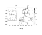
- FIG. 6 illustrates results of an angle of polarization analysis on the captured image of FIG. 4 .
- FIG. 7 is a flowchart illustrating an example security method.
- FIG. 8 illustrates layers of a camera of the security system of FIG. 1 in accordance with an alternative embodiment.
- a polarization camera is implemented with a security system to obtain polarized information of light reflected from an object captured in an image by the camera.
- This polarized information may be used in the determination of whether the object captured in the image is three-dimensional and/or if the object manifests human/living characteristics.
- These techniques may help improve security by preventing the use of photographs of individuals and/or inanimate busts of the same to bypass security based on facial recognition.
- Access to a goal which may be physical (e.g., an object) or virtual (e.g., data) may be controlled by the techniques, methods and/or systems described herein.
- a polarization camera is based on the natural phenomenon that when unpolarized light, such as sunlight, is reflected by an object surface or human face, it becomes partially polarized.
- the first is specular reflection, where light is directly reflected by a smooth surface.
- the second type of reflection mechanism is diffuse reflection, where the light reflects off a rough surface, or penetrates into the material's surface and reflects out after several internal reflections inside the material. In most natural environments, diffuse reflection is dominant form of reflection and can be used to identify a person or object.
- polarization data at different polarization angles may be obtained.
- DOLP degree of linear polarization
- AOP angle of polarization
- an image based security system may further utilize these polarization parameter for helping to ensure that a physical person is present rather than simply an image of the person.
- movements of the individual may be utilized such as, pulse and/or respiration rate; movement of eyes, jaw, cheeks, lips, head and/or clothing; or other such movements to help ensure that a 3D model or other device is not used in an attempt to bypass the security system.
- FIG. 1 illustrates an image based security system 100 .
- the image based security system 100 generally includes a camera 102 , a processing system 104 and a database 106 .
- the camera 102 may take the form of a digital camera configured to capture images of individuals desiring access to a particular location, computer, system, network, and/or so forth. Generally, the camera 102 is configured with a polarizer, as discussed in greater detail below.
- the processing system 104 may take any suitable form, such as a desktop computer, notebook computer, application specific integrated circuit, and so forth, and is configured to compare images captured by the camera 102 with those stored in the database 106 .
- the database 106 may include images of individuals for which access may be granted. As an initial measure of security, recognition of an individual as being included in the database 106 based upon characteristics of the individual may be implemented. Various techniques are known in the art for facial recognition for these purposes and one or more of these may be implemented.
- the database 106 may include images of individuals that are of interest for some reason. For example, if there are individuals who have been known to attempt, or have an interest in attempting to bypass the security system 100 . Alerts may be trigged upon recognizing one of these individuals.
- one or more components may be located remotely from the other components.
- the camera 102 may be located at an entrance point of a facility and may be in communication with the processing system 104 located at a security base for the facility.
- the processing system 104 may communicate with the database 106 via a network (e.g., local area network, wide area network, the Internet, and/or so forth) which may or may not be co-located with the processing system.
- each component of the system 100 may be included within a single housing. That is, for example, the camera 102 , the processing system 104 , and the database 106 may be housed within a single housing, such as in a notebook or tablet computing device, for example.
- FIG. 2 illustrates a block diagram of a security system 118 as it may be implemented in a single computing system.
- the system 118 may include a memory 108 and I/o devices 110 .
- a digital signal processing (DSP) unit 112 may be coupled to the camera 102 in some embodiments.
- the DSP unit 112 may includes a dedicated processing unit(s) that are provided to process the images captured by the camera 102 . This may alleviate the processing burden on the processing system 104 which may be a central processing unit for the system 100 .
- the DSP unit 112 may be configured to compute the DOLP, AOP and surface normals for images captured by the camera 102 , while in other embodiments, the processing system 104 performs these calculations.
- the camera 102 includes a polarizer 114 which is also shown in FIG. 3 .
- FIG. 3 illustrates layers included in the optical path for image capture.
- a light sensor 120 detects light that passes through a Bayer layer 122 and the polarizer 114 .
- the light sensor 120 may take any suitable form including a charge coupled device (CCD) sensor or a complementary metallic-oxide semiconductor (CMOS) sensor.
- CMOS complementary metallic-oxide semiconductor
- the Bayer layer 122 is a color filter that filters red, green and blue components of light.
- the Bayer layer 122 is divided into four block squares with each square including two green blocks, one red block and one blue block. This is due, at least in part, on the relative sensitivity of the human eye to green colors.
- the blocks correspond in a one to one ratio with the pixels of the light sensor 120 .
- the polarizer 114 is a linear polarizer (e.g., a laminate wire grid polarizer) and is configured to filter polarized light based on the angle of the polarized light.
- the polarizer may be divided into four block squares with the blocks being at 0, 45, 90 and ⁇ 45 degrees polarization angles.
- a four block square 130 is shown inset.
- Each block of the four block square may correspond with a single pixel of a captured image. As such, four images may be generated at 1 ⁇ 4 resolution of the sensor 120 .
- each block may correspond with a particular color block of the Bayer layer 122 .
- the polarizer 114 may be integrated into the Bayer layer 122 , while in other embodiments the polarizer 114 may be a separate layer.
- the digital camera 102 with the polarizer 114 was used to capture an image of a person (3D object) next to a 2D picture of that person to demonstrate the ability to distinguish between a 2D object and a 3D object.
- FIG. 4 illustrates the 2D image 132 next to the person 134 .
- FIGS. 5 and 6 illustrate the resulting image after stokes parameters are used for computing DOLP and AOP, respectively.
- Stokes parameters are generally used to describe polarized light.
- the Stokes parameters describe the polarization state in terms of measurable intensities.
- S 0 I 0 +I 90 ;
- S i I 0 +I 90 ;
- S 2 I 45 ⁇ I 45 ;
- I 0 , I 45 , I ⁇ 45 , and I 90 are the measured intensity values of the light through the polarizer oriented at 0°, 45°, ⁇ 45° and 90° respectively.
- This formula is used in the practical application because the required parameters I 0° , I 90° , I +45 , and I ⁇ 45° , can be easily obtained by measuring the light intensity after passing through the polarization filter along different axis (e.g., by putting a polarization filter along vertical axis, the light intensity recorded behind this filter is I 0° ).
- the degree of linear polarization, angle of polarization and surface normals can be calculated for each of the pixels of the captured image. Specifically:
- SN x cos ( ⁇ )sin( ⁇ );
- SN y sin( ⁇ )sin( ⁇ );
- SN z cos ( ⁇ ); where the zenith angle ⁇ , is calculated by numerical solving the equation:
- n is the refractive index of the surface material. It should be appreciated that other formulas may be utilized to calculate the DOLP and AOP, such as, for example,
- FIG. 5 illustrates the difference in the degree of linear polarization between the 2D picture 132 ′ and the person 134 ′.
- the scale running along the left side and bottom is number of pixels, although any other suitable scale may be implemented.
- the degree of polarization is illustrated with increasing dot density, as indicated in the right side-bar.
- the degree of polarization may be shown in different ways, for example the degree of polarization may be color-coded (e.g., certain colors may indicate a greater degree of polarization).
- the degree of polarization may simply be indicated in numerical form (e.g., in a grid or array) with numbers indicating the degree of polarization.
- the degree of polarization is a determination as to how much of the captured light is polarized. Because the 2D picture 132 is flat, the polarization is uniform across the picture. Hence, it is difficult to discern any shapes or features within the portion of the illustration in which the picture is located. In contrast, the 3D image of the person 134 ′ shows areas where there is variance in the polarization due to curvature of the face, shoulders, etc. Hence, the degree of polarization metric may be used to determine if a captured image is of a 2D or 3D object by simply scanning for changes in the degree of linear polarization in the image.
- scanning for changes in the degree of linear polarization may include using threshold values (such as a variance from a baseline value that may represent the degree of linear polarization for a flat object) as indicating a 3D object.
- analysis may include determining if a certain number of pixels exhibit non-uniform degree of linear polarization.
- more complex analysis may be implemented to evaluate if an image of 3D object has been captured based on the degree of linear polarization.
- the rendering of the images to represent the degree of polarization may include a color coded image that indicates the degree of polarization for the individual pixels. For example, in some embodiments, 0 degree of polarization may be indicated by a dark blue color, pixels having greater polarization may be represented by green, yellow, orange and red colors, so that differences in degrees of polarization may be visual discerned. In other embodiments, an array of numbers may be generated that represent the degree of linear polarization and the numerical values of each pixel may be compared with other pixe3l values.
- FIG. 6 illustrates the difference in the angle of polarization between the 2D picture 132 and the person 134 .
- FIG. 6 has the same scale as FIG. 5 and, again, uses dot density for indicating angle or polarization although other techniques may be implemented as well.
- the flat 2D picture 132 ′′ has a uniform angle of polarization.
- the image of the 3D person 134 ′′ has a variety of angles of polarization due to the reflecting of light off different contours.
- the angle of polarization may be utilized in the determination of whether an object is 2D or 3D in a similar manner as the degree of linear polarization (e.g., analyze the data to find changes/differences in the angle of polarization).
- the degree of polarization and angle of polarization may be used to calculate surface normals.
- the surface normals are vectors that are normal to the surface. As the 2D picture is planer, the surface normals will all be directed in the same direction. In contrast, the surface normals of a 3D object, such as the person, will be pointing in different directions.
- the calculation of surface normals may be useful in recreating a three dimensional rendering of the object. However, it should be appreciated, that the surface normals may be computed and analyzed independent of recreating the object.
- Every material has a unique reflective property which results in unique values for DOLP and AOP.
- Other factors can be used to differentiate the inanimate object from an actual human by taking motion into consideration. These include but are not limited to: movement of the eyes; subtle movement of the jaws, cheeks, lips; vertical translation of the head during breathing; movement of clothing; and pulse rate, among others. Recognition of these motion nuances and comparing them to unique nuances of human motion can further increase the accuracy of the security systems.
- the camera 102 may be configured to capture video images of objects. Further, multiple frames of the captured video may be analyzed and compared against each other. Specifically, the degree of polarization, angle of polarization, and/or surface normals may be computed on a single frame, initially, to determine if an object is three dimensional. Subsequently, if it is three-dimensional, the same calculations may be performed on multiple frames and then compared against each other to determine if human characteristic movements are exhibited.
- FIG. 7 is a flow chart illustrating a method 150 for providing facial recognition security.
- the method may initially include obtaining a first image of an individual (Block 152 ).
- the first image is stored in the database for comparison with subsequently acquired images.
- the first image may be obtained without the use of a polarizing camera. That is, in some embodiments, the first image may be utilized solely for the purpose of comparing facial metrics to determine if two images are of a substantially similar individual.
- a second image is later acquired (Block 154 ).
- the second image is acquired using a polarizing camera (e.g., a camera with a polarizer).
- the second image is compared with the first image (Block 156 ) to determine if the second image is substantially the same as the first image (Block 158 ) or that they are of the same person, object and the like (e.g., there are sufficient common metrics between the two images such that it may be determined that they are of the same person/object).
- the database may be searched to see if the second image corresponds to another image in the database. If the second image does not correspond to any of the images in the database, then a negative result may be provided (e.g., access may be denied) (Block 160 ).
- the degree of polarization, angle of polarization and/or surface normals are computed and analyzed to determine if characteristics of a 2D or 3D object are manifested (e.g., substantially uniform results indicate a 2D object, whereas non-uniform results indicate a 3D object) (Block 162 ).
- it is determined if the second image is of a 3D object (Block 164 ). If the determination is made that the second image is of a 2D object, then a negative result may be provided (Block 160 ). In some embodiments, if it is determined that the second image is of a 3D object, a positive result may be provided (e.g., access granted).
- the camera may capture video images (Block 166 ) and differences between the images may be analyzed to determine if the object is alive (e.g., not a mannequin or a bust of a person).
- small scale movements as opposed to macro movements
- periodic movements corresponding to pulse rate or respiration e.g., movement of the head
- non-periodic movements such as movements of the jaw, cheeks, lips, and so on, may indicate that the object in the second image is living.
- multiple frames may be compared against each other to detect movements.
- the small movements may be readily discernable when analyzing images based on the degree of polarization and/or angle of polarization, as any movement that changes the way light is reflected off the object will be shown. If the micro movements are indicative of a human then a positive result may be provided, such as providing access (Block 170 ).
- a security system may be implemented that utilizes the data in a captured polarized image to perform a function, such as disabling security or initiating an alert, or control access to an object, whether physical or virtual.
- the security system may open a door if a subject is recognized and the appropriate security checks are passed (such as determining that the person in the captured image is three-dimensional and/or exhibits motion associated with a live person) and may keep the door locked and closed if not.
- the security system may utilize images containing polarized data not only for physical security, but also for electronic of virtual security.
- security systems may be implemented using the technology described herein to control access to electronic systems and/or data.
- security systems incorporating concepts herein may initiate or otherwise control alarm systems.
- FIG. 8 illustrates an alternative embodiment for polarizing a captured image.
- the image capture stack includes the photosensor 120 and the Bayer layer 122 , but instead of a grid polarizer having four different polarizing angles, such as that shown in FIG. 3 , a polarizer 180 may have a single polarizing axis.
- the polarizer 180 may be configured to rotate in order to achieve the appropriate polarization angles. That is, as the polarizer having only a single axis of polarization is rotated, the photosensor may capture images when it is at 0, 45, 90 and ⁇ 45 degrees. Hence, four different images are captured at four different times.
Abstract
One embodiment may take the form of a method for providing security for access to a goal including storing a first image and receiving a second image comprising polarized data. The method also includes comparing the first image with the second image to determine if the first image and the second image are substantially the same. In the event the first and second images are not substantially the same, the method includes denying access to the goal. In the event the first and second images are substantially the same, the method includes determining, utilizing the polarized information, if the second image is of a three-dimensional object. Further, in the event the second image is not of a three-dimensional object, the method includes denying access to the goal and, in the event the second image is of a three-dimensional object, permitting access to the goal.
Description
This application is a continuation of U.S. patent application Ser. No. 13/088,286, filed Apr. 15, 2011, entitled “Polarized Images for Security,” which claims the benefit under 35 U.S.C. §119(e) of U.S. Provisional Patent Application No. 61/386,865, filed on Sep. 27, 2010, entitled “Image Capture Using Three-Dimensional Reconstruction,” the disclosures of which are incorporated by reference as if fully disclosed herein
The present disclosure relates to using images for security and, more particularly, to using polarized images for security
Facial recognition software has been used in a variety of different contexts. One use that has seen particular interest has been facial recognition for security. In one example, an image may be captured of a computer user and the image is compared against a stored image to determine if the user may access the computer. In comparing the captured image with the stored image, a variety of metrics may be utilized to determine if the images correspond. For example, ratios related to particular features may be used such as the length of the nose to the width of the eyes or the length from the nose to the chin to the width between the cheek bones. In some embodiments, raw measurements and/or unique features may be utilized. Generally, however, current facial recognition software is unable to distinguish when a human is replaced with a photograph or other object. As such, a security system based on facial recognition may be bypassed by simply providing a photograph of a verifiable user
Security techniques and systems are provided. In particular, the techniques may include facial recognition security features combined with a determination as to whether an object captured in an image is a three-dimensional object. This determination is based on polarization characteristics contained in the captured image.
One embodiment may take the form of a method for providing security for access to a goal including storing a first image and receiving a second image comprising polarized data.
The method also includes comparing the first image with the second image to determine if the first image and the second image are substantially the same. In the event the first and second images are not substantially the same, the method includes denying access to the goal. In the event the first and second images are substantially the same, the method includes determining, utilizing the polarized information, if the second image is of a three-dimensional object. Further, in the event the second image is not of a three-dimensional object, the method includes denying access to the goal and, in the event the second image is of a three-dimensional object, permitting access to the goal.
Another embodiment may take the form of a security system including a polarizing image capture device and a processor coupled to the polarizing image capture device. A storage device coupled to the processor and operative to store a group of stored images. The processor is configured to compare images captured by the image capture device with at least one of the group of stored images. Additionally, the processor is configured to determine if an image captured by the polarizing image capture device is of a three-dimensional object.
Yet another embodiment may take the form of a security system having a processor and a camera coupled to the processor. The camera includes a photosensor, a Bayer layer, and a polarizing filter. The processor is configured to analyze images captured by the camera and determine if an object in the image is a three dimensional object based at least in part upon variance in one of a degree of polarization, angle of polarization, and surface normals of the captured image.
While multiple embodiments are disclosed, still other embodiments of the present invention will become apparent to those skilled in the art from the following Detailed Description. As will be realized, the embodiments are capable of modifications in various aspects, all without departing from the spirit and scope of the embodiments. Accordingly, the drawings and detailed description are to be regarded as illustrative in nature and not restrictive.
Generally, a polarization camera is implemented with a security system to obtain polarized information of light reflected from an object captured in an image by the camera. This polarized information may be used in the determination of whether the object captured in the image is three-dimensional and/or if the object manifests human/living characteristics. These techniques may help improve security by preventing the use of photographs of individuals and/or inanimate busts of the same to bypass security based on facial recognition. Access to a goal, which may be physical (e.g., an object) or virtual (e.g., data) may be controlled by the techniques, methods and/or systems described herein.
A polarization camera is based on the natural phenomenon that when unpolarized light, such as sunlight, is reflected by an object surface or human face, it becomes partially polarized. There are two physical mechanisms in the reflection process. The first is specular reflection, where light is directly reflected by a smooth surface. The second type of reflection mechanism is diffuse reflection, where the light reflects off a rough surface, or penetrates into the material's surface and reflects out after several internal reflections inside the material. In most natural environments, diffuse reflection is dominant form of reflection and can be used to identify a person or object.
By using a standard digital camera with a linear polarizer in front of the lens, polarization data at different polarization angles may be obtained. Using three or more polarized images, an estimate of the degree of linear polarization (DOLP) and the angle of polarization (AOP) per pixel may be calculated. These values can then be used to determine the zenith angle and the azimuth angle, which in turn define the surface normal for a particular pixel.
Generally, a two-dimensional (2D) image has a small change in DOLP, AOP and surface normal, as the surface is flat. In contrast, a three-dimensional (3D) object or human face has a significant difference in DOLP, AOP and surface normal. As such, an image based security system may further utilize these polarization parameter for helping to ensure that a physical person is present rather than simply an image of the person. Additionally, in some implementations, movements of the individual may be utilized such as, pulse and/or respiration rate; movement of eyes, jaw, cheeks, lips, head and/or clothing; or other such movements to help ensure that a 3D model or other device is not used in an attempt to bypass the security system.
Additionally, in some embodiments, the database 106 may include images of individuals that are of interest for some reason. For example, if there are individuals who have been known to attempt, or have an interest in attempting to bypass the security system 100. Alerts may be trigged upon recognizing one of these individuals.
In some embodiments, one or more components may be located remotely from the other components. For example, the camera 102 may be located at an entrance point of a facility and may be in communication with the processing system 104 located at a security base for the facility. The processing system 104 may communicate with the database 106 via a network (e.g., local area network, wide area network, the Internet, and/or so forth) which may or may not be co-located with the processing system. In other embodiments, each component of the system 100 may be included within a single housing. That is, for example, the camera 102, the processing system 104, and the database 106 may be housed within a single housing, such as in a notebook or tablet computing device, for example.
The camera 102 includes a polarizer 114 which is also shown in FIG. 3 . FIG. 3 illustrates layers included in the optical path for image capture. A light sensor 120 detects light that passes through a Bayer layer 122 and the polarizer 114. The light sensor 120 may take any suitable form including a charge coupled device (CCD) sensor or a complementary metallic-oxide semiconductor (CMOS) sensor. The Bayer layer 122 is a color filter that filters red, green and blue components of light. The Bayer layer 122 is divided into four block squares with each square including two green blocks, one red block and one blue block. This is due, at least in part, on the relative sensitivity of the human eye to green colors. In some embodiments, the blocks correspond in a one to one ratio with the pixels of the light sensor 120.
The polarizer 114 is a linear polarizer (e.g., a laminate wire grid polarizer) and is configured to filter polarized light based on the angle of the polarized light. Specifically, the polarizer may be divided into four block squares with the blocks being at 0, 45, 90 and −45 degrees polarization angles. A four block square 130 is shown inset. Each block of the four block square may correspond with a single pixel of a captured image. As such, four images may be generated at ¼ resolution of the sensor 120. Moreover, each block may correspond with a particular color block of the Bayer layer 122. In some embodiments, the polarizer 114 may be integrated into the Bayer layer 122, while in other embodiments the polarizer 114 may be a separate layer.
The digital camera 102 with the polarizer 114 was used to capture an image of a person (3D object) next to a 2D picture of that person to demonstrate the ability to distinguish between a 2D object and a 3D object. FIG. 4 illustrates the 2D image 132 next to the person 134. FIGS. 5 and 6 illustrate the resulting image after stokes parameters are used for computing DOLP and AOP, respectively.
By way of providing background, Stokes parameters are generally used to describe polarized light. The Stokes parameters describe the polarization state in terms of measurable intensities.
S 0 =I 0 +I 90;
S i =I 0 +I 90;
S 2 =I 45−I45;
S 0 =I 0 +I 90;
S i =I 0 +I 90;
S 2 =I 45−I45;
where I0, I45, I−45, and I90 are the measured intensity values of the light through the polarizer oriented at 0°, 45°, −45° and 90° respectively. This formula is used in the practical application because the required parameters I0°, I90°, I+45, and I−45°, can be easily obtained by measuring the light intensity after passing through the polarization filter along different axis (e.g., by putting a polarization filter along vertical axis, the light intensity recorded behind this filter is I0°).
From the Stokes parameters, the degree of linear polarization, angle of polarization and surface normals can be calculated for each of the pixels of the captured image. Specifically:
and the surface normal components in X, Y, and Z planes are given by:
SN x=cos (α)sin(θ);
SN y=sin(α)sin(θ);
SN z=cos (θ);
where the zenith angle θ, is calculated by numerical solving the equation:
and n is the refractive index of the surface material. It should be appreciated that other formulas may be utilized to calculate the DOLP and AOP, such as, for example,
where Arg is the angle of the complex number. ∥ ∥ is the absolute value of the complex number.
Generally, the degree of polarization is a determination as to how much of the captured light is polarized. Because the 2D picture 132 is flat, the polarization is uniform across the picture. Hence, it is difficult to discern any shapes or features within the portion of the illustration in which the picture is located. In contrast, the 3D image of the person 134′ shows areas where there is variance in the polarization due to curvature of the face, shoulders, etc. Hence, the degree of polarization metric may be used to determine if a captured image is of a 2D or 3D object by simply scanning for changes in the degree of linear polarization in the image.
In some embodiments, scanning for changes in the degree of linear polarization may include using threshold values (such as a variance from a baseline value that may represent the degree of linear polarization for a flat object) as indicating a 3D object. Additionally, or alternatively, analysis may include determining if a certain number of pixels exhibit non-uniform degree of linear polarization. In still other embodiments, more complex analysis may be implemented to evaluate if an image of 3D object has been captured based on the degree of linear polarization.
In some embodiments, the rendering of the images to represent the degree of polarization may include a color coded image that indicates the degree of polarization for the individual pixels. For example, in some embodiments, 0 degree of polarization may be indicated by a dark blue color, pixels having greater polarization may be represented by green, yellow, orange and red colors, so that differences in degrees of polarization may be visual discerned. In other embodiments, an array of numbers may be generated that represent the degree of linear polarization and the numerical values of each pixel may be compared with other pixe3l values.
The degree of polarization and angle of polarization may be used to calculate surface normals. The surface normals are vectors that are normal to the surface. As the 2D picture is planer, the surface normals will all be directed in the same direction. In contrast, the surface normals of a 3D object, such as the person, will be pointing in different directions. The calculation of surface normals may be useful in recreating a three dimensional rendering of the object. However, it should be appreciated, that the surface normals may be computed and analyzed independent of recreating the object.
Every material has a unique reflective property which results in unique values for DOLP and AOP. Assuming it is possible to fabricate a 3D bust of a human face and duplicate the reflective property of skin, other factors can be used to differentiate the inanimate object from an actual human by taking motion into consideration. These include but are not limited to: movement of the eyes; subtle movement of the jaws, cheeks, lips; vertical translation of the head during breathing; movement of clothing; and pulse rate, among others. Recognition of these motion nuances and comparing them to unique nuances of human motion can further increase the accuracy of the security systems.
In order to detect the acute movements, the camera 102 may be configured to capture video images of objects. Further, multiple frames of the captured video may be analyzed and compared against each other. Specifically, the degree of polarization, angle of polarization, and/or surface normals may be computed on a single frame, initially, to determine if an object is three dimensional. Subsequently, if it is three-dimensional, the same calculations may be performed on multiple frames and then compared against each other to determine if human characteristic movements are exhibited.
A second image is later acquired (Block 154). The second image is acquired using a polarizing camera (e.g., a camera with a polarizer). The second image is compared with the first image (Block 156) to determine if the second image is substantially the same as the first image (Block 158) or that they are of the same person, object and the like (e.g., there are sufficient common metrics between the two images such that it may be determined that they are of the same person/object). In the event that the first and second images are not of the same person, the database may be searched to see if the second image corresponds to another image in the database. If the second image does not correspond to any of the images in the database, then a negative result may be provided (e.g., access may be denied) (Block 160).
If the first and second image are determined to be of the same person, the degree of polarization, angle of polarization and/or surface normals are computed and analyzed to determine if characteristics of a 2D or 3D object are manifested (e.g., substantially uniform results indicate a 2D object, whereas non-uniform results indicate a 3D object) (Block 162). Thus, it is determined if the second image is of a 3D object (Block 164). If the determination is made that the second image is of a 2D object, then a negative result may be provided (Block 160). In some embodiments, if it is determined that the second image is of a 3D object, a positive result may be provided (e.g., access granted).
Additionally, in some embodiments, if it has been determined that the object in the second image is a 3D object further analysis may be performed to determine if the object is living and/or human. For example, the camera may capture video images (Block 166) and differences between the images may be analyzed to determine if the object is alive (e.g., not a mannequin or a bust of a person). Generally, small scale movements (as opposed to macro movements) may be used for such determinations (Block 168). Specifically, periodic movements corresponding to pulse rate or respiration (e.g., movement of the head) may be used. Further, non-periodic movements, such as movements of the jaw, cheeks, lips, and so on, may indicate that the object in the second image is living.
As such, multiple frames may be compared against each other to detect movements. The small movements may be readily discernable when analyzing images based on the degree of polarization and/or angle of polarization, as any movement that changes the way light is reflected off the object will be shown. If the micro movements are indicative of a human then a positive result may be provided, such as providing access (Block 170).
[It should be appreciated that certain operations discussed above and shown in FIG. 7 may bee omitted in some embodiments, and/or the order of certain operations may be changed. For example, some embodiments may omit blocks 166 and 168. Yet others may determine whether or not an image depicts a three-dimensional object/person prior to attempting to match that image against a known image or person. Accordingly, the operations shown in FIG. 7 and the order thereof are illustrative of a single embodiment and not meant to be limiting.
Generally, a security system may be implemented that utilizes the data in a captured polarized image to perform a function, such as disabling security or initiating an alert, or control access to an object, whether physical or virtual. As one example, the security system may open a door if a subject is recognized and the appropriate security checks are passed (such as determining that the person in the captured image is three-dimensional and/or exhibits motion associated with a live person) and may keep the door locked and closed if not. Likewise, the security system may utilize images containing polarized data not only for physical security, but also for electronic of virtual security. As one example, security systems may be implemented using the technology described herein to control access to electronic systems and/or data. As still another option, security systems incorporating concepts herein may initiate or otherwise control alarm systems.
The foregoing discussion describes some example embodiments for providing security based at least in part upon capturing a polarized image. Although the foregoing discussion has presented specific embodiments, persons skilled in the art will recognize that changes may be made in form and detail without departing from the spirit and scope of the embodiments. Specifically, for example, as the polarization of light and the ability to detect the polarization of light may be dependent upon and may vary based on a variety of factors such as ambient lighting, the systems 100 and 118 may be provided with an incoherent light source that may be directed at the object being captured. This may help facilitate consistency among captured images. Accordingly, the specific embodiments described herein should be understood as examples and not limiting the scope thereof.
Claims (20)
1. A method for providing facial recognition security, comprising receiving a first image of an individual captured by a polarizing image capture device;
comparing facial metrics in the first image to facial metrics in a second image of the individual to determine if the first and second images are of the same individual;
if the first and second images are of the same individual, determining if the first image is of a three-dimensional object based on polarized data in the image;
if the first image is of a three-dimensional object, comparing the first image with one or more other images of the individual captured by the polarizing image capture device to determine if a micro-movement indicative of a human occurred between the first image and at least one of the one or more other images; and
if a micro-movement indicative of a human occurred between the first and at least one of the one or more other images, providing a positive result to the individual.
2. The method as in claim 1 , wherein the positive result comprises granting access to the individual.
3. The method as in claim 1 , further comprising denying access to the individual if a micro-movement indicative of a human did not occur between the first and the one or more other images.
4. The method as in claim 1 , further comprising denying access to the individual if the first image is not of a three-dimensional object.
5. The method as in claim 1 , further comprising denying access to the individual if the first and second images are not of the same individual.
6. The method as in claim 5 , further comprising generating an alert when the first and second images are not of the same individual.
7. The method as in claim 1 , further comprising:
if the first and second images are not of the same individual, searching a database of images of individuals to determine if the first image corresponds to another image in the database; and
if the first image does not match any images in the database of images, denying access to the individual.
8. The method as in claim 1 , wherein the second image is one of the one or more other images captured by the polarizing image capture device.
9. The method as in claim 1 , wherein determining if the first image is of a three-dimensional object based on the polarized data comprises computing at least one of a degree of linear polarization, an angle of polarization, and a surface normal.
10. The method as in claim 9 , further comprising computing stokes parameters to compute at least one of the degree of linear polarization, the angle of polarization, and the surface normal.
11. The method as in claim 1 , wherein the one or more micro-movements indicative of a human comprises at least one of:
a respiratory movement;
a movement induced by a pulse rate; and
an eye movement;
a movement of the head;
a movement of the lips; and
a movement of clothing worn by the individual.
12. A security system comprising:
a camera comprising a photosensor and a polarizer, the camera capturing images of an individual;
a processor coupled to the camera; and a storage device coupled to the processor and operative to store one or more images of an individual;
wherein the processor is configured to compare at least one captured image of the individual with the one or more stored images to determine if the at least one captured image and the one or more stored images are of the same individual;
wherein the processor is configured to determine if at least one captured image is of a three-dimensional object based on polarized data in the image,
wherein the processor is configured to determine if one or more micro-movements indicative of a human occurred between the captured images; and
wherein the processor is further configured to grant access to the individual if at least one captured image and at least one stored image are of the same individual, if at least one image of the individual captured by the camera is of a three-dimensional object, and if one or more micro-movements indicative of a human occurred between the images.
13. The security system as in claim 12 , wherein the processor is further configured to deny access to the individual if at least one image of the individual captured by the camera is of a three-dimensional object.
14. The security system as in claim 12 , wherein the processor is further configured to deny access to the individual if one or more micro-movements indicative of a human did not occur between the images.
15. The security system as in claim 12 , wherein the processor is further configured to generate an alert and deny access to the individual if individual in the captured images does not match at least one individual in the stored images.
16. The security system as in claim 12 , wherein the processor is configured to compute at least one of a degree of linear polarization, an angle of polarization and a surface normal for the captured image when determining if at least one image of the individual captured by the camera is of a three-dimensional object.
17. The security system as in claim 12 , wherein the polarizer comprises a linear polarizer divided into four blocks with the blocks having polarization angles of 0, 45, 90, and −45 degrees.
18. The security system as in claim 17 , wherein the linear polarizer is integrated into a Bayer layer.
19. The security system as in claim 17 , wherein a Bayer layer is disposed between the photosensor and the linear polarizer and each block of the linear polarizer corresponds to a distinct pixel of each captured image and to a particular color block of the Bayer layer.
20. The security system as in claim 12 , wherein the polarizer has a single polarizing axis and the polarizer is configured to rotate to capture multiple images at different polarization angles.
Priority Applications (1)
| Application Number | Priority Date | Filing Date | Title |
|---|---|---|---|
| US14/279,648 US9536362B2 (en) | 2010-09-27 | 2014-05-16 | Polarized images for security |
Applications Claiming Priority (3)
| Application Number | Priority Date | Filing Date | Title |
|---|---|---|---|
| US38686510P | 2010-09-27 | 2010-09-27 | |
| US13/088,286 US8760517B2 (en) | 2010-09-27 | 2011-04-15 | Polarized images for security |
| US14/279,648 US9536362B2 (en) | 2010-09-27 | 2014-05-16 | Polarized images for security |
Related Parent Applications (1)
| Application Number | Title | Priority Date | Filing Date |
|---|---|---|---|
| US13/088,286 Continuation US8760517B2 (en) | 2010-09-27 | 2011-04-15 | Polarized images for security |
Publications (2)
| Publication Number | Publication Date |
|---|---|
| US20140247361A1 US20140247361A1 (en) | 2014-09-04 |
| US9536362B2 true US9536362B2 (en) | 2017-01-03 |
Family
ID=44947179
Family Applications (3)
| Application Number | Title | Priority Date | Filing Date |
|---|---|---|---|
| US13/088,286 Active 2031-12-26 US8760517B2 (en) | 2010-09-27 | 2011-04-15 | Polarized images for security |
| US13/246,821 Abandoned US20120075432A1 (en) | 2010-09-27 | 2011-09-27 | Image capture using three-dimensional reconstruction |
| US14/279,648 Active 2032-05-29 US9536362B2 (en) | 2010-09-27 | 2014-05-16 | Polarized images for security |
Family Applications Before (2)
| Application Number | Title | Priority Date | Filing Date |
|---|---|---|---|
| US13/088,286 Active 2031-12-26 US8760517B2 (en) | 2010-09-27 | 2011-04-15 | Polarized images for security |
| US13/246,821 Abandoned US20120075432A1 (en) | 2010-09-27 | 2011-09-27 | Image capture using three-dimensional reconstruction |
Country Status (3)
| Country | Link |
|---|---|
| US (3) | US8760517B2 (en) |
| TW (1) | TWI489858B (en) |
| WO (1) | WO2012044619A1 (en) |
Cited By (4)
| Publication number | Priority date | Publication date | Assignee | Title |
|---|---|---|---|---|
| US10402624B2 (en) | 2011-05-12 | 2019-09-03 | Apple Inc. | Presence sensing |
| US10817594B2 (en) | 2017-09-28 | 2020-10-27 | Apple Inc. | Wearable electronic device having a light field camera usable to perform bioauthentication from a dorsal side of a forearm near a wrist |
| US11741584B2 (en) * | 2018-11-13 | 2023-08-29 | Genesys Logic, Inc. | Method for correcting an image and device thereof |
| US11927769B2 (en) | 2022-03-31 | 2024-03-12 | Metalenz, Inc. | Polarization sorting metasurface microlens array device |
Families Citing this family (89)
| Publication number | Priority date | Publication date | Assignee | Title |
|---|---|---|---|---|
| US20100030040A1 (en) | 2008-08-04 | 2010-02-04 | Masimo Laboratories, Inc. | Multi-stream data collection system for noninvasive measurement of blood constituents |
| EP2326239B1 (en) | 2008-07-03 | 2017-06-21 | Masimo Laboratories, Inc. | Protrusion for improving spectroscopic measurement of blood constituents |
| KR100933175B1 (en) * | 2009-02-05 | 2009-12-21 | 이영범 | System and method for monitoring restricted documents |
| US20110082711A1 (en) | 2009-10-06 | 2011-04-07 | Masimo Laboratories, Inc. | Personal digital assistant or organizer for monitoring glucose levels |
| JP5421364B2 (en) * | 2010-01-05 | 2014-02-19 | パナソニック株式会社 | 3D imaging device |
| US9408542B1 (en) | 2010-07-22 | 2016-08-09 | Masimo Corporation | Non-invasive blood pressure measurement system |
| US8760517B2 (en) | 2010-09-27 | 2014-06-24 | Apple Inc. | Polarized images for security |
| EP2509324A1 (en) * | 2011-04-08 | 2012-10-10 | Thomson Licensing | Method and apparatus for analyzing stereoscopic or multi-view images |
| KR101660215B1 (en) | 2011-05-12 | 2016-09-26 | 애플 인크. | Presence sensing |
| US20130027548A1 (en) * | 2011-07-28 | 2013-01-31 | Apple Inc. | Depth perception device and system |
| WO2013108285A1 (en) * | 2012-01-16 | 2013-07-25 | パナソニック株式会社 | Image recording device, three-dimensional image reproduction device, image recording method, and three-dimensional image reproduction method |
| US9435888B1 (en) * | 2012-03-26 | 2016-09-06 | The United States Of America As Represented By The Secretary Of The Navy | Shape matching automatic recognition methods, systems and articles of manufacturing |
| US8937591B2 (en) | 2012-04-06 | 2015-01-20 | Apple Inc. | Systems and methods for counteracting a perceptual fading of a movable indicator |
| JP5933357B2 (en) * | 2012-06-13 | 2016-06-08 | 株式会社Pfu | Overhead image reader |
| US9128188B1 (en) * | 2012-07-13 | 2015-09-08 | The United States Of America As Represented By The Secretary Of The Navy | Object instance identification using template textured 3-D model matching |
| US8994780B2 (en) | 2012-10-04 | 2015-03-31 | Mcci Corporation | Video conferencing enhanced with 3-D perspective control |
| TWI571827B (en) * | 2012-11-13 | 2017-02-21 | 財團法人資訊工業策進會 | Electronic device and method for determining depth of 3d object image in 3d environment image |
| TWI525382B (en) * | 2012-11-21 | 2016-03-11 | 豪威科技股份有限公司 | Camera array systems including at least one bayer type camera and associated methods |
| TWI591584B (en) * | 2012-12-26 | 2017-07-11 | 財團法人工業技術研究院 | Three dimensional sensing method and three dimensional sensing apparatus |
| WO2014143276A2 (en) | 2012-12-31 | 2014-09-18 | Omni Medsci, Inc. | Short-wave infrared super-continuum lasers for natural gas leak detection, exploration, and other active remote sensing applications |
| EP2938259A4 (en) | 2012-12-31 | 2016-08-17 | Omni Medsci Inc | Near-infrared lasers for non-invasive monitoring of glucose, ketones, hba1c, and other blood constituents |
| US10660526B2 (en) | 2012-12-31 | 2020-05-26 | Omni Medsci, Inc. | Near-infrared time-of-flight imaging using laser diodes with Bragg reflectors |
| US9667883B2 (en) | 2013-01-07 | 2017-05-30 | Eminent Electronic Technology Corp. Ltd. | Three-dimensional image sensing device and method of sensing three-dimensional images |
| US9101320B2 (en) | 2013-04-09 | 2015-08-11 | Elc Management Llc | Skin diagnostic and image processing methods |
| US9256963B2 (en) | 2013-04-09 | 2016-02-09 | Elc Management Llc | Skin diagnostic and image processing systems, apparatus and articles |
| US10497140B2 (en) * | 2013-08-15 | 2019-12-03 | Intel Corporation | Hybrid depth sensing pipeline |
| US20150103200A1 (en) * | 2013-10-16 | 2015-04-16 | Broadcom Corporation | Heterogeneous mix of sensors and calibration thereof |
| WO2015087323A1 (en) * | 2013-12-09 | 2015-06-18 | Mantisvision Ltd | Emotion based 3d visual effects |
| KR102227284B1 (en) | 2014-01-16 | 2021-03-12 | 삼성전자주식회사 | Dispaly apparatus and controlling method thereof |
| WO2015152984A2 (en) * | 2014-01-22 | 2015-10-08 | Polaris Sensor Technologies, Inc. | Polarization imaging for facial recognition enhancement system and method |
| US9589195B2 (en) | 2014-01-22 | 2017-03-07 | Polaris Sensor Technologies, Inc. | Polarization-based mapping and perception method and system |
| US10395113B2 (en) * | 2014-01-22 | 2019-08-27 | Polaris Sensor Technologies, Inc. | Polarization-based detection and mapping method and system |
| US8952818B1 (en) | 2014-03-18 | 2015-02-10 | Jack Ke Zhang | Fall detection apparatus with floor and surface elevation learning capabilites |
| US9293023B2 (en) | 2014-03-18 | 2016-03-22 | Jack Ke Zhang | Techniques for emergency detection and emergency alert messaging |
| CN104954776A (en) | 2014-03-24 | 2015-09-30 | 宏达国际电子股份有限公司 | Method of image correction and image capturing device thereof |
| TWI589149B (en) * | 2014-04-29 | 2017-06-21 | 鈺立微電子股份有限公司 | Portable three-dimensional scanner and method of generating a three-dimensional scan result corresponding to an object |
| CN105025193B (en) | 2014-04-29 | 2020-02-07 | 钰立微电子股份有限公司 | Portable stereo scanner and method for generating stereo scanning result of corresponding object |
| US20150348323A1 (en) * | 2014-06-02 | 2015-12-03 | Lenovo (Singapore) Pte. Ltd. | Augmenting a digital image with distance data derived based on actuation of at least one laser |
| US9324136B2 (en) * | 2014-06-12 | 2016-04-26 | Htc Corporation | Method, electronic apparatus, and computer readable medium for processing reflection in image |
| US20150373320A1 (en) * | 2014-06-24 | 2015-12-24 | Photon-X | Visual cognition system |
| US11206388B2 (en) | 2014-12-01 | 2021-12-21 | Sony Corporation | Image processing apparatus and image processing method for aligning polarized images based on a depth map and acquiring a polarization characteristic using the aligned polarized images |
| US9197082B1 (en) | 2014-12-09 | 2015-11-24 | Jack Ke Zhang | Techniques for power source management using a wrist-worn device |
| CN104599365A (en) * | 2014-12-31 | 2015-05-06 | 苏州福丰科技有限公司 | Flat open induction door control system and method based on three-dimensional facial image recognition |
| GB201501311D0 (en) * | 2015-01-27 | 2015-03-11 | Apical Ltd | Method, system and computer program product |
| WO2016136086A1 (en) | 2015-02-27 | 2016-09-01 | ソニー株式会社 | Imaging device, image processing device and image processing method |
| US10432842B2 (en) * | 2015-04-06 | 2019-10-01 | The Texas A&M University System | Fusion of inertial and depth sensors for movement measurements and recognition |
| US9300925B1 (en) * | 2015-05-04 | 2016-03-29 | Jack Ke Zhang | Managing multi-user access to controlled locations in a facility |
| US10448871B2 (en) | 2015-07-02 | 2019-10-22 | Masimo Corporation | Advanced pulse oximetry sensor |
| CN105069883A (en) * | 2015-08-19 | 2015-11-18 | 湖州高鼎智能科技有限公司 | Human body comparison intelligent lock system |
| DE102015116026A1 (en) | 2015-09-22 | 2017-03-23 | JENETRIC GmbH | Device and method for direct optical image acquisition of documents and / or living skin areas without imaging optical elements |
| KR102457724B1 (en) * | 2015-09-22 | 2022-10-24 | 삼성전자주식회사 | Method for performing image process and electronic device thereof |
| JP6556013B2 (en) * | 2015-10-08 | 2019-08-07 | キヤノン株式会社 | PROCESSING DEVICE, PROCESSING SYSTEM, IMAGING DEVICE, PROCESSING METHOD, PROGRAM, AND RECORDING MEDIUM |
| US9830506B2 (en) | 2015-11-09 | 2017-11-28 | The United States Of America As Represented By The Secretary Of The Army | Method of apparatus for cross-modal face matching using polarimetric image data |
| CN105959667A (en) * | 2016-07-06 | 2016-09-21 | 南京捷特普智能科技有限公司 | Three-dimensional image collection device and system |
| CN106127908A (en) * | 2016-07-27 | 2016-11-16 | 北京集创北方科技股份有限公司 | Living things feature recognition lock and control method thereof |
| US10538326B1 (en) * | 2016-08-31 | 2020-01-21 | Amazon Technologies, Inc. | Flare detection and avoidance in stereo vision systems |
| TWI624170B (en) * | 2016-10-19 | 2018-05-11 | 財團法人工業技術研究院 | Image scanning system and method thereof |
| DE102017205619A1 (en) * | 2017-04-03 | 2018-10-04 | Robert Bosch Gmbh | LiDAR system and method for operating a LiDAR system |
| US10462444B2 (en) * | 2017-04-17 | 2019-10-29 | Faro Technologies, Inc. | Three-dimensional inspection |
| JP2018195241A (en) * | 2017-05-22 | 2018-12-06 | ソニー株式会社 | Information processing apparatus, information processing method, and program |
| US10108261B1 (en) * | 2017-07-05 | 2018-10-23 | Oculus Vr, Llc | Eye tracking based on light polarization |
| EP3660449A4 (en) * | 2017-07-26 | 2020-08-12 | Sony Corporation | Information processing device, information processing method, and program |
| KR102399539B1 (en) * | 2017-08-28 | 2022-05-19 | 삼성전자주식회사 | Method and apparatus for identifying an object |
| JP6963295B2 (en) * | 2017-09-01 | 2021-11-05 | 学校法人東京電機大学 | 3D information acquisition device |
| CN107680156B (en) * | 2017-09-08 | 2020-06-05 | 西安电子科技大学 | Three-dimensional reconstruction method based on polarization information |
| CN107635129B (en) * | 2017-09-29 | 2020-06-16 | 上海安威士科技股份有限公司 | Three-dimensional trinocular camera device and depth fusion method |
| US11678035B2 (en) | 2017-10-05 | 2023-06-13 | University Of Utah Research Foundation | Translucent imaging systems and related methods |
| US10311584B1 (en) | 2017-11-09 | 2019-06-04 | Facebook Technologies, Llc | Estimation of absolute depth from polarization measurements |
| US20210150744A1 (en) * | 2017-12-20 | 2021-05-20 | Olympus Corporation | System and method for hybrid depth estimation |
| US11048374B2 (en) * | 2018-03-08 | 2021-06-29 | Ebay Inc. | Online pluggable 3D platform for 3D representations of items |
| EP3578126B1 (en) * | 2018-06-08 | 2023-02-22 | Stryker European Operations Holdings LLC | Surgical navigation system |
| CN109191560B (en) * | 2018-06-29 | 2021-06-15 | 西安电子科技大学 | Monocular polarization three-dimensional reconstruction method based on scattering information correction |
| US10598838B2 (en) * | 2018-06-29 | 2020-03-24 | Intel Corporation | Pixel level polarizer for flexible display panels |
| EP3824621A4 (en) | 2018-07-19 | 2022-04-27 | Activ Surgical, Inc. | Systems and methods for multi-modal sensing of depth in vision systems for automated surgical robots |
| US10630925B1 (en) * | 2018-12-03 | 2020-04-21 | Facebook Technologies, Llc | Depth determination using polarization of light and camera assembly with augmented pixels |
| US10791282B2 (en) | 2018-12-13 | 2020-09-29 | Fenwick & West LLP | High dynamic range camera assembly with augmented pixels |
| US10855896B1 (en) | 2018-12-13 | 2020-12-01 | Facebook Technologies, Llc | Depth determination using time-of-flight and camera assembly with augmented pixels |
| US10791286B2 (en) | 2018-12-13 | 2020-09-29 | Facebook Technologies, Llc | Differentiated imaging using camera assembly with augmented pixels |
| CN109886166A (en) * | 2019-01-31 | 2019-06-14 | 杭州创匠信息科技有限公司 | Method for anti-counterfeit and device based on polarization characteristic |
| EP3708948B1 (en) * | 2019-03-12 | 2021-09-22 | Sick Ag | A light line triangulation apparatus |
| CA3132350A1 (en) | 2019-04-08 | 2020-10-15 | Stephen Tully | Systems and methods for medical imaging |
| US10921450B2 (en) | 2019-04-24 | 2021-02-16 | Aeye, Inc. | Ladar system and method with frequency domain shuttering |
| CN110708353A (en) * | 2019-09-03 | 2020-01-17 | 上海派拉软件技术有限公司 | Database risk control method based on Mysql agent |
| US11405601B2 (en) | 2019-09-17 | 2022-08-02 | Meta Platforms Technologies, Llc | Polarization capture device, system, and method |
| US11783444B1 (en) * | 2019-11-14 | 2023-10-10 | Apple Inc. | Warping an input image based on depth and offset information |
| US10902623B1 (en) | 2019-11-19 | 2021-01-26 | Facebook Technologies, Llc | Three-dimensional imaging with spatial and temporal coding for depth camera assembly |
| US11194160B1 (en) | 2020-01-21 | 2021-12-07 | Facebook Technologies, Llc | High frame rate reconstruction with N-tap camera sensor |
| CN112528942A (en) * | 2020-12-23 | 2021-03-19 | 深圳市汇顶科技股份有限公司 | Fingerprint identification device, display screen and electronic equipment |
| CN112912766B (en) * | 2021-02-02 | 2022-10-04 | 华为技术有限公司 | Detection device, control method, fusion detection system and terminal |
Citations (60)
| Publication number | Priority date | Publication date | Assignee | Title |
|---|---|---|---|---|
| US4437089A (en) | 1980-06-24 | 1984-03-13 | S.A. Promocab | Dual sensitivity intrusion detection system |
| US5903350A (en) | 1997-02-03 | 1999-05-11 | Optiphase, Inc. | Demodulator and method useful for multiplexed optical sensors |
| US6072894A (en) * | 1997-10-17 | 2000-06-06 | Payne; John H. | Biometric face recognition for applicant screening |
| US6146332A (en) | 1998-07-29 | 2000-11-14 | 3416704 Canada Inc. | Movement detector |
| US6359664B1 (en) | 1990-06-11 | 2002-03-19 | Reveo, Inc. | Electro-optical display system for visually displaying polarized spatially multiplexed images of 3-D objects for use in stereoscopically viewing the same with high image quality and resolution |
| US20020158750A1 (en) | 2001-04-30 | 2002-10-31 | Almalik Mansour Saleh | System, method and portable device for biometric identification |
| JP2002350555A (en) | 2001-05-28 | 2002-12-04 | Yamaha Motor Co Ltd | Human presence detector |
| US20030108341A1 (en) | 1996-12-04 | 2003-06-12 | Matsushita Electric Industrial Co., Ltd. | Optical disk for high resolution and three-dimensional video recording, optical disk reproduction apparatus, and optical disk recording apparatus |
| US20030142853A1 (en) | 2001-11-08 | 2003-07-31 | Pelco | Security identification system |
| US6603502B2 (en) | 1991-05-13 | 2003-08-05 | Internet Pictures Corporation | System for omnidirectional image viewing at a remote location without the transmission of control signals to select viewing parameters |
| US6775397B1 (en) | 2000-02-24 | 2004-08-10 | Nokia Corporation | Method and apparatus for user recognition using CCD cameras |
| US6802016B2 (en) | 2001-02-08 | 2004-10-05 | Twinhead International Corp. | User proximity sensor and signal processing circuitry for determining whether to power a computer on or off |
| JP2004348349A (en) | 2003-05-21 | 2004-12-09 | Masayuki Watabiki | Household appliance power controller |
| US6832006B2 (en) | 2001-07-23 | 2004-12-14 | Eastman Kodak Company | System and method for controlling image compression based on image emphasis |
| US20050071698A1 (en) | 2003-09-30 | 2005-03-31 | Kangas Paul Daniel | Apparatus, system, and method for autonomic power adjustment in an electronic device |
| US20050221791A1 (en) | 2004-04-05 | 2005-10-06 | Sony Ericsson Mobile Communications Ab | Sensor screen saver |
| US7006236B2 (en) | 2002-05-22 | 2006-02-28 | Canesta, Inc. | Method and apparatus for approximating depth of an object's placement onto a monitored region with applications to virtual interface devices |
| US7009378B2 (en) | 2003-09-05 | 2006-03-07 | Nxtphase T & D Corporation | Time division multiplexed optical measuring system |
| EP1672460A1 (en) | 2004-12-15 | 2006-06-21 | STMicroelectronics (Research & Development) Limited | Computer user detection apparatus |
| US20060274177A1 (en) | 2005-05-16 | 2006-12-07 | Funai Electric Co., Ltd. | Image processing apparatus |
| US7151530B2 (en) | 2002-08-20 | 2006-12-19 | Canesta, Inc. | System and method for determining an input selected by a user through a virtual interface |
| US7164781B2 (en) | 2002-03-04 | 2007-01-16 | Samsung Electronics Co., Ltd. | Method and apparatus of recognizing face using 2nd-order independent component analysis (ICA)/principal component analysis (PCA) |
| JP2007519317A (en) | 2003-12-09 | 2007-07-12 | アウェアーポイント コーポレーション | Plug-in network device |
| US20070172099A1 (en) | 2006-01-13 | 2007-07-26 | Samsung Electronics Co., Ltd. | Scalable face recognition method and apparatus based on complementary features of face image |
| US20070223078A1 (en) | 2003-03-12 | 2007-09-27 | Yao X S | Polarization measurement and self-calibration based on multiple tunable optical polarization rotators |
| US7369685B2 (en) | 2002-04-05 | 2008-05-06 | Identix Corporation | Vision-based operating method and system |
| US20080170123A1 (en) | 2007-01-12 | 2008-07-17 | Jacob C Albertson | Tracking a range of body movement based on 3d captured image streams of a user |
| US20090015666A1 (en) | 2002-04-10 | 2009-01-15 | Kendro Laboratory Products Lp | Automated protein crystallization imaging |
| GB2453163A (en) | 2007-09-26 | 2009-04-01 | Christopher Douglas Blair | Three dimensional imaging by multiple image capture under different illumination conditions |
| US7536037B2 (en) | 2003-11-19 | 2009-05-19 | Samsung Electronics Co., Ltd. | Apparatus and method for human distinction using infrared light |
| US20090190846A1 (en) | 2006-06-06 | 2009-07-30 | Koninklijke Philips Electronics N.V. | Scaling an image based on a motion vector |
| US20090219251A1 (en) | 2008-02-28 | 2009-09-03 | Yung Woo Jung | Virtual optical input device with feedback and method of controlling the same |
| US20090297020A1 (en) | 2008-05-29 | 2009-12-03 | Beardsley Paul A | Method and system for determining poses of semi-specular objects |
| US20100008900A1 (en) | 2008-07-14 | 2010-01-14 | The University Of Hong Kong | Annexin ii compositions for treating or monitoring inflammation or immune-mediated disorders |
| US20100013951A1 (en) * | 2004-06-24 | 2010-01-21 | Rodriguez Tony F | Digital Watermarking Methods, Programs and Apparatus |
| CN101639800A (en) | 2008-08-01 | 2010-02-03 | 华为技术有限公司 | Display method of screen and terminal |
| WO2010021375A1 (en) | 2008-08-22 | 2010-02-25 | 国立大学法人大阪大学 | Process for production of protease, protease solution, and solution of pro-form of protease |
| DE102008047413A1 (en) | 2008-09-16 | 2010-04-15 | Hella Kgaa Hueck & Co. | Motor vehicle object detection system has a stereo camera with two gray image sensors and a mono camera with a color image sensor |
| WO2010073547A1 (en) | 2008-12-25 | 2010-07-01 | パナソニック株式会社 | Image processing device and pseudo-3d image creation device |
| EP2216999A1 (en) | 2007-12-07 | 2010-08-11 | Panasonic Corporation | Image processing device, image processing method, and imaging device |
| WO2010095075A1 (en) | 2009-02-20 | 2010-08-26 | Koninklijke Philips Electronics N.V. | System, method and apparatus for causing a device to enter an active mode |
| US20100231522A1 (en) | 2005-02-23 | 2010-09-16 | Zienon, Llc | Method and apparatus for data entry input |
| US7806604B2 (en) * | 2005-10-20 | 2010-10-05 | Honeywell International Inc. | Face detection and tracking in a wide field of view |
| US20100253782A1 (en) | 2009-04-07 | 2010-10-07 | Latent Image Technology Ltd. | Device and method for automated verification of polarization-variant images |
| WO2010113075A1 (en) | 2009-03-31 | 2010-10-07 | Koninklijke Philips Electronics N. V. | Energy efficient cascade of sensors for automatic presence detection |
| WO2010127488A1 (en) | 2009-05-07 | 2010-11-11 | Joemel Caballero | System for controlling light emission of television |
| US20100328074A1 (en) | 2009-06-30 | 2010-12-30 | Johnson Erik J | Human presence detection techniques |
| US7903166B2 (en) | 2007-02-21 | 2011-03-08 | Sharp Laboratories Of America, Inc. | Methods and systems for display viewer motion compensation based on user image data |
| US20110074989A1 (en) | 2009-09-25 | 2011-03-31 | Samsung Electronics Co., Ltd. | Image sensors |
| US7929729B2 (en) | 2007-04-02 | 2011-04-19 | Industrial Technology Research Institute | Image processing methods |
| EP2315439A1 (en) | 2008-08-22 | 2011-04-27 | Sony Corporation | Image display device, control method and computer program |
| US20110262044A1 (en) | 2010-04-21 | 2011-10-27 | Elitegroup Computer Systems Co., Ltd. | Energy saving method for electronic device |
| US20120036261A1 (en) | 2010-08-05 | 2012-02-09 | Qualcomm Incorporated | Communication management utilizing destination device user presence probability |
| US20120075473A1 (en) | 2010-09-27 | 2012-03-29 | Apple Inc. | Polarized images for security |
| US8154615B2 (en) | 2009-06-30 | 2012-04-10 | Eastman Kodak Company | Method and apparatus for image display control according to viewer factors and responses |
| US8264536B2 (en) | 2009-08-25 | 2012-09-11 | Microsoft Corporation | Depth-sensitive imaging via polarization-state mapping |
| US20120287031A1 (en) | 2011-05-12 | 2012-11-15 | Apple Inc. | Presence sensing |
| US20120287035A1 (en) | 2011-05-12 | 2012-11-15 | Apple Inc. | Presence Sensing |
| US8345086B2 (en) | 2008-09-09 | 2013-01-01 | Sony Corporation | Apparatus, method, and computer program for analyzing image data |
| US8912877B2 (en) | 2011-02-18 | 2014-12-16 | Blackberry Limited | System and method for activating an electronic device using two or more sensors |
Family Cites Families (39)
| Publication number | Priority date | Publication date | Assignee | Title |
|---|---|---|---|---|
| US5028138A (en) * | 1989-05-23 | 1991-07-02 | Wolff Lawrence B | Method of and apparatus for obtaining object data by machine vision form polarization information |
| EP0717569A3 (en) * | 1994-12-16 | 2000-03-01 | Terumo Kabushiki Kaisha | Stereoscopic ocular fundus camera |
| US5793374A (en) * | 1995-07-28 | 1998-08-11 | Microsoft Corporation | Specialized shaders for shading objects in computer generated images |
| US6028608A (en) * | 1997-05-09 | 2000-02-22 | Jenkins; Barry | System and method of perception-based image generation and encoding |
| US6766036B1 (en) * | 1999-07-08 | 2004-07-20 | Timothy R. Pryor | Camera based man machine interfaces |
| US7031497B2 (en) * | 2001-11-05 | 2006-04-18 | Koninklijke Philips Electronics N.V. | Method for computing optical flow under the epipolar constraint |
| FR2852128A1 (en) * | 2003-03-07 | 2004-09-10 | France Telecom | METHOD FOR MANAGING THE REPRESENTATION OF AT LEAST ONE MODELIZED 3D SCENE |
| JP3944458B2 (en) * | 2003-03-12 | 2007-07-11 | 株式会社ソフィア | Image display device and game machine |
| US7256780B2 (en) * | 2004-03-04 | 2007-08-14 | Siemens Medical Solutions Usa, Inc. | Visualization of volume-rendered data with occluding contour multi-planar-reformats |
| DE102004040372B4 (en) * | 2004-08-20 | 2006-06-29 | Diehl Avionik Systeme Gmbh | Method and device for displaying a three-dimensional topography |
| US7262767B2 (en) * | 2004-09-21 | 2007-08-28 | Victor Company Of Japan, Limited | Pseudo 3D image creation device, pseudo 3D image creation method, and pseudo 3D image display system |
| US7483065B2 (en) * | 2004-12-15 | 2009-01-27 | Aptina Imaging Corporation | Multi-lens imaging systems and methods using optical filters having mosaic patterns |
| WO2006086579A2 (en) * | 2005-02-09 | 2006-08-17 | Inlight Solutions, Inc. | Methods and apparatus for noninvasive determinations of analytes |
| US7583372B2 (en) * | 2005-06-01 | 2009-09-01 | Hunter Engineering Company | Machine vision vehicle wheel alignment image processing methods |
| CA2553473A1 (en) * | 2005-07-26 | 2007-01-26 | Wa James Tam | Generating a depth map from a tw0-dimensional source image for stereoscopic and multiview imaging |
| FR2891375B1 (en) * | 2005-09-29 | 2008-02-15 | Essilor Int | POLARIZING OPHTHALMIC LENS ADAPTED TO THE BEHAVIOR EYE / HEAD OF A BEARER. |
| US7723662B2 (en) * | 2005-10-07 | 2010-05-25 | The Board Of Trustees Of The Leland Stanford Junior University | Microscopy arrangements and approaches |
| US7582857B2 (en) * | 2006-04-18 | 2009-09-01 | The Trustees Of The University Of Pennsylvania | Sensor and polarimetric filters for real-time extraction of polarimetric information at the focal plane |
| JP4077869B2 (en) * | 2006-05-29 | 2008-04-23 | 松下電器産業株式会社 | Light source estimation device, light source estimation system, light source estimation method, image resolution increasing device, and image resolution increasing method |
| AU2007275714A1 (en) * | 2006-07-18 | 2008-01-24 | The Trustees Of The University Of Pennsylvania | Separation and contrast enhancement of overlapping cast shadow components and target detection in shadow using polarization |
| US8509965B2 (en) * | 2006-12-12 | 2013-08-13 | American Gnc Corporation | Integrated collision avoidance system for air vehicle |
| EP2202688B1 (en) * | 2007-02-13 | 2013-11-20 | Panasonic Corporation | System, method and apparatus for image processing and image format |
| US8619127B2 (en) * | 2007-05-10 | 2013-12-31 | Assad F. Mora | Stereoscopic three dimensional visualization system and method of use |
| WO2009020277A1 (en) * | 2007-08-06 | 2009-02-12 | Samsung Electronics Co., Ltd. | Method and apparatus for reproducing stereoscopic image using depth control |
| EP2026097A1 (en) * | 2007-08-08 | 2009-02-18 | Harman Becker Automotive Systems GmbH | Vehicle illumination system |
| US7782364B2 (en) * | 2007-08-21 | 2010-08-24 | Aptina Imaging Corporation | Multi-array sensor with integrated sub-array for parallax detection and photometer functionality |
| US8786595B2 (en) * | 2008-06-10 | 2014-07-22 | Pinpoint 3D | Systems and methods for estimating a parameter for a 3D model |
| US7964840B2 (en) * | 2008-06-19 | 2011-06-21 | Omnivision Technologies, Inc. | High dynamic range image sensor including polarizer and microlens |
| JP4435865B2 (en) * | 2008-06-26 | 2010-03-24 | パナソニック株式会社 | Image processing apparatus, image division program, and image composition method |
| CN102138333B (en) * | 2008-08-29 | 2014-09-24 | 汤姆逊许可公司 | View synthesis with heuristic view blending |
| US8665258B2 (en) * | 2008-09-16 | 2014-03-04 | Adobe Systems Incorporated | Generating a depth map based on a single image |
| EP2370846A4 (en) * | 2008-11-27 | 2013-12-11 | Canon Kk | Solid-state image sensing element and image sensing apparatus |
| US8576226B2 (en) * | 2008-12-02 | 2013-11-05 | Disney Enterprises, Inc. | Tertiary lighting system |
| KR20100073191A (en) | 2008-12-22 | 2010-07-01 | 한국전자통신연구원 | Method and apparatus for face liveness using range data |
| US8466960B2 (en) * | 2009-02-16 | 2013-06-18 | Ricoh Company, Ltd. | Liquid droplet recognition apparatus, raindrop recognition apparatus, and on-vehicle monitoring apparatus |
| US20100283885A1 (en) * | 2009-05-11 | 2010-11-11 | Shih-Schon Lin | Method for aligning pixilated micro-grid polarizer to an image sensor |
| US20100302235A1 (en) * | 2009-06-02 | 2010-12-02 | Horizon Semiconductors Ltd. | efficient composition of a stereoscopic image for a 3-D TV |
| JP5421364B2 (en) * | 2010-01-05 | 2014-02-19 | パナソニック株式会社 | 3D imaging device |
| US8879902B2 (en) * | 2010-10-08 | 2014-11-04 | Vincent Pace & James Cameron | Integrated 2D/3D camera with fixed imaging parameters |
-
2011
- 2011-04-15 US US13/088,286 patent/US8760517B2/en active Active
- 2011-09-27 WO PCT/US2011/053485 patent/WO2012044619A1/en active Application Filing
- 2011-09-27 US US13/246,821 patent/US20120075432A1/en not_active Abandoned
- 2011-09-27 TW TW100134847A patent/TWI489858B/en not_active IP Right Cessation
-
2014
- 2014-05-16 US US14/279,648 patent/US9536362B2/en active Active
Patent Citations (71)
| Publication number | Priority date | Publication date | Assignee | Title |
|---|---|---|---|---|
| US4437089A (en) | 1980-06-24 | 1984-03-13 | S.A. Promocab | Dual sensitivity intrusion detection system |
| US6359664B1 (en) | 1990-06-11 | 2002-03-19 | Reveo, Inc. | Electro-optical display system for visually displaying polarized spatially multiplexed images of 3-D objects for use in stereoscopically viewing the same with high image quality and resolution |
| US6603502B2 (en) | 1991-05-13 | 2003-08-05 | Internet Pictures Corporation | System for omnidirectional image viewing at a remote location without the transmission of control signals to select viewing parameters |
| US7317868B2 (en) | 1996-12-04 | 2008-01-08 | Matsushita Electric Industrial Co., Ltd. | Optical disk for high resolution and three-dimensional video recording, optical disk reproduction apparatus, and optical disk recording apparatus |
| US20030108341A1 (en) | 1996-12-04 | 2003-06-12 | Matsushita Electric Industrial Co., Ltd. | Optical disk for high resolution and three-dimensional video recording, optical disk reproduction apparatus, and optical disk recording apparatus |
| US5903350A (en) | 1997-02-03 | 1999-05-11 | Optiphase, Inc. | Demodulator and method useful for multiplexed optical sensors |
| US6072894A (en) * | 1997-10-17 | 2000-06-06 | Payne; John H. | Biometric face recognition for applicant screening |
| US6146332A (en) | 1998-07-29 | 2000-11-14 | 3416704 Canada Inc. | Movement detector |
| US6775397B1 (en) | 2000-02-24 | 2004-08-10 | Nokia Corporation | Method and apparatus for user recognition using CCD cameras |
| US6802016B2 (en) | 2001-02-08 | 2004-10-05 | Twinhead International Corp. | User proximity sensor and signal processing circuitry for determining whether to power a computer on or off |
| US20020158750A1 (en) | 2001-04-30 | 2002-10-31 | Almalik Mansour Saleh | System, method and portable device for biometric identification |
| JP2002350555A (en) | 2001-05-28 | 2002-12-04 | Yamaha Motor Co Ltd | Human presence detector |
| US6832006B2 (en) | 2001-07-23 | 2004-12-14 | Eastman Kodak Company | System and method for controlling image compression based on image emphasis |
| US20030142853A1 (en) | 2001-11-08 | 2003-07-31 | Pelco | Security identification system |
| US7136513B2 (en) | 2001-11-08 | 2006-11-14 | Pelco | Security identification system |
| US7164781B2 (en) | 2002-03-04 | 2007-01-16 | Samsung Electronics Co., Ltd. | Method and apparatus of recognizing face using 2nd-order independent component analysis (ICA)/principal component analysis (PCA) |
| US7369685B2 (en) | 2002-04-05 | 2008-05-06 | Identix Corporation | Vision-based operating method and system |
| US20090015666A1 (en) | 2002-04-10 | 2009-01-15 | Kendro Laboratory Products Lp | Automated protein crystallization imaging |
| US7006236B2 (en) | 2002-05-22 | 2006-02-28 | Canesta, Inc. | Method and apparatus for approximating depth of an object's placement onto a monitored region with applications to virtual interface devices |
| US7151530B2 (en) | 2002-08-20 | 2006-12-19 | Canesta, Inc. | System and method for determining an input selected by a user through a virtual interface |
| US7436569B2 (en) | 2003-03-12 | 2008-10-14 | General Photonics Corporation | Polarization measurement and self-calibration based on multiple tunable optical polarization rotators |
| US20070223078A1 (en) | 2003-03-12 | 2007-09-27 | Yao X S | Polarization measurement and self-calibration based on multiple tunable optical polarization rotators |
| JP2004348349A (en) | 2003-05-21 | 2004-12-09 | Masayuki Watabiki | Household appliance power controller |
| US7009378B2 (en) | 2003-09-05 | 2006-03-07 | Nxtphase T & D Corporation | Time division multiplexed optical measuring system |
| US20050071698A1 (en) | 2003-09-30 | 2005-03-31 | Kangas Paul Daniel | Apparatus, system, and method for autonomic power adjustment in an electronic device |
| US7117380B2 (en) | 2003-09-30 | 2006-10-03 | International Business Machines Corporation | Apparatus, system, and method for autonomic power adjustment in an electronic device |
| US7536037B2 (en) | 2003-11-19 | 2009-05-19 | Samsung Electronics Co., Ltd. | Apparatus and method for human distinction using infrared light |
| JP2007519317A (en) | 2003-12-09 | 2007-07-12 | アウェアーポイント コーポレーション | Plug-in network device |
| US7324824B2 (en) | 2003-12-09 | 2008-01-29 | Awarepoint Corporation | Wireless network monitoring system |
| US20050221791A1 (en) | 2004-04-05 | 2005-10-06 | Sony Ericsson Mobile Communications Ab | Sensor screen saver |
| US20100013951A1 (en) * | 2004-06-24 | 2010-01-21 | Rodriguez Tony F | Digital Watermarking Methods, Programs and Apparatus |
| EP1672460A1 (en) | 2004-12-15 | 2006-06-21 | STMicroelectronics (Research & Development) Limited | Computer user detection apparatus |
| US20100231522A1 (en) | 2005-02-23 | 2010-09-16 | Zienon, Llc | Method and apparatus for data entry input |
| US20060274177A1 (en) | 2005-05-16 | 2006-12-07 | Funai Electric Co., Ltd. | Image processing apparatus |
| US7806604B2 (en) * | 2005-10-20 | 2010-10-05 | Honeywell International Inc. | Face detection and tracking in a wide field of view |
| US20070172099A1 (en) | 2006-01-13 | 2007-07-26 | Samsung Electronics Co., Ltd. | Scalable face recognition method and apparatus based on complementary features of face image |
| US20090190846A1 (en) | 2006-06-06 | 2009-07-30 | Koninklijke Philips Electronics N.V. | Scaling an image based on a motion vector |
| US8462989B2 (en) | 2006-06-06 | 2013-06-11 | Tp Vision Holding B.V. | Scaling an image based on a motion vector |
| US7840031B2 (en) | 2007-01-12 | 2010-11-23 | International Business Machines Corporation | Tracking a range of body movement based on 3D captured image streams of a user |
| US20080170123A1 (en) | 2007-01-12 | 2008-07-17 | Jacob C Albertson | Tracking a range of body movement based on 3d captured image streams of a user |
| US7903166B2 (en) | 2007-02-21 | 2011-03-08 | Sharp Laboratories Of America, Inc. | Methods and systems for display viewer motion compensation based on user image data |
| US7929729B2 (en) | 2007-04-02 | 2011-04-19 | Industrial Technology Research Institute | Image processing methods |
| GB2453163A (en) | 2007-09-26 | 2009-04-01 | Christopher Douglas Blair | Three dimensional imaging by multiple image capture under different illumination conditions |
| EP2216999A1 (en) | 2007-12-07 | 2010-08-11 | Panasonic Corporation | Image processing device, image processing method, and imaging device |
| US20090219251A1 (en) | 2008-02-28 | 2009-09-03 | Yung Woo Jung | Virtual optical input device with feedback and method of controlling the same |
| US8698753B2 (en) | 2008-02-28 | 2014-04-15 | Lg Electronics Inc. | Virtual optical input device with feedback and method of controlling the same |
| US20090297020A1 (en) | 2008-05-29 | 2009-12-03 | Beardsley Paul A | Method and system for determining poses of semi-specular objects |
| US8107721B2 (en) | 2008-05-29 | 2012-01-31 | Mitsubishi Electric Research Laboratories, Inc. | Method and system for determining poses of semi-specular objects |
| US20100008900A1 (en) | 2008-07-14 | 2010-01-14 | The University Of Hong Kong | Annexin ii compositions for treating or monitoring inflammation or immune-mediated disorders |
| CN101639800A (en) | 2008-08-01 | 2010-02-03 | 华为技术有限公司 | Display method of screen and terminal |
| WO2010021375A1 (en) | 2008-08-22 | 2010-02-25 | 国立大学法人大阪大学 | Process for production of protease, protease solution, and solution of pro-form of protease |
| EP2315439A1 (en) | 2008-08-22 | 2011-04-27 | Sony Corporation | Image display device, control method and computer program |
| US8345086B2 (en) | 2008-09-09 | 2013-01-01 | Sony Corporation | Apparatus, method, and computer program for analyzing image data |
| DE102008047413A1 (en) | 2008-09-16 | 2010-04-15 | Hella Kgaa Hueck & Co. | Motor vehicle object detection system has a stereo camera with two gray image sensors and a mono camera with a color image sensor |
| WO2010073547A1 (en) | 2008-12-25 | 2010-07-01 | パナソニック株式会社 | Image processing device and pseudo-3d image creation device |
| WO2010095075A1 (en) | 2009-02-20 | 2010-08-26 | Koninklijke Philips Electronics N.V. | System, method and apparatus for causing a device to enter an active mode |
| US8880865B2 (en) | 2009-02-20 | 2014-11-04 | Koninklijke Philips N.V. | System, method and apparatus for causing a device to enter an active mode |
| WO2010113075A1 (en) | 2009-03-31 | 2010-10-07 | Koninklijke Philips Electronics N. V. | Energy efficient cascade of sensors for automatic presence detection |
| US20100253782A1 (en) | 2009-04-07 | 2010-10-07 | Latent Image Technology Ltd. | Device and method for automated verification of polarization-variant images |
| WO2010127488A1 (en) | 2009-05-07 | 2010-11-11 | Joemel Caballero | System for controlling light emission of television |
| US20100328074A1 (en) | 2009-06-30 | 2010-12-30 | Johnson Erik J | Human presence detection techniques |
| US8154615B2 (en) | 2009-06-30 | 2012-04-10 | Eastman Kodak Company | Method and apparatus for image display control according to viewer factors and responses |
| US8264536B2 (en) | 2009-08-25 | 2012-09-11 | Microsoft Corporation | Depth-sensitive imaging via polarization-state mapping |
| US20110074989A1 (en) | 2009-09-25 | 2011-03-31 | Samsung Electronics Co., Ltd. | Image sensors |
| US20110262044A1 (en) | 2010-04-21 | 2011-10-27 | Elitegroup Computer Systems Co., Ltd. | Energy saving method for electronic device |
| US20120036261A1 (en) | 2010-08-05 | 2012-02-09 | Qualcomm Incorporated | Communication management utilizing destination device user presence probability |
| US20120075432A1 (en) | 2010-09-27 | 2012-03-29 | Apple Inc. | Image capture using three-dimensional reconstruction |
| US20120075473A1 (en) | 2010-09-27 | 2012-03-29 | Apple Inc. | Polarized images for security |
| US8912877B2 (en) | 2011-02-18 | 2014-12-16 | Blackberry Limited | System and method for activating an electronic device using two or more sensors |
| US20120287035A1 (en) | 2011-05-12 | 2012-11-15 | Apple Inc. | Presence Sensing |
| US20120287031A1 (en) | 2011-05-12 | 2012-11-15 | Apple Inc. | Presence sensing |
Non-Patent Citations (3)
| Title |
|---|
| Rahmann et al., "Reconstruction of Specular Surfaces Using Polarization Imaging," Proceedings of the IEEE Computer Conference on Computer Vision and Pattern Recognition, pp. I-149-I-155, 2001. |
| Sano et al., "Submicron Spaced Lens Array Process Technology for a High Photosensitivity CCD Image Sensor," IEEE, pp. 283-286, Dec. 1990. |
| Wolff et al., "Polarization Camera Sensors," Image and Vision Computing, pp. 497-510, vol. 13, No. 6, Aug. 1995. |
Cited By (5)
| Publication number | Priority date | Publication date | Assignee | Title |
|---|---|---|---|---|
| US10402624B2 (en) | 2011-05-12 | 2019-09-03 | Apple Inc. | Presence sensing |
| US10817594B2 (en) | 2017-09-28 | 2020-10-27 | Apple Inc. | Wearable electronic device having a light field camera usable to perform bioauthentication from a dorsal side of a forearm near a wrist |
| US11036844B2 (en) | 2017-09-28 | 2021-06-15 | Apple Inc. | Wearable electronic device having a light field camera |
| US11741584B2 (en) * | 2018-11-13 | 2023-08-29 | Genesys Logic, Inc. | Method for correcting an image and device thereof |
| US11927769B2 (en) | 2022-03-31 | 2024-03-12 | Metalenz, Inc. | Polarization sorting metasurface microlens array device |
Also Published As
| Publication number | Publication date |
|---|---|
| US20120075473A1 (en) | 2012-03-29 |
| US8760517B2 (en) | 2014-06-24 |
| WO2012044619A1 (en) | 2012-04-05 |
| TW201230773A (en) | 2012-07-16 |
| US20140247361A1 (en) | 2014-09-04 |
| TWI489858B (en) | 2015-06-21 |
| US20120075432A1 (en) | 2012-03-29 |
Similar Documents
| Publication | Publication Date | Title |
|---|---|---|
| US9536362B2 (en) | Polarized images for security | |
| Smith et al. | Gaze locking: passive eye contact detection for human-object interaction | |
| CN105912986B (en) | A kind of biopsy method and system | |
| Hordley | Scene illuminant estimation: past, present, and future | |
| US7065232B2 (en) | Three-dimensional ear biometrics system and method | |
| US8090160B2 (en) | Automated method for human face modeling and relighting with application to face recognition | |
| Steiner et al. | Design of an active multispectral SWIR camera system for skin detection and face verification | |
| Nishino et al. | The world in an eye [eye image interpretation] | |
| US11710289B2 (en) | Information processing apparatus, information processing system, and material identification method | |
| US20210342578A1 (en) | Polarization Imaging for Facial Recognition Enhancement System and Method | |
| CN109640821A (en) | For face detection/identifying system method and apparatus | |
| CN106236061A (en) | Human body detection device | |
| KR20150080728A (en) | Acquisition System and Method of Iris image for iris recognition by using facial component distance | |
| CN109670390A (en) | Living body face recognition method and system | |
| EP3241151A1 (en) | An image face processing method and apparatus | |
| TWM364920U (en) | 3D human face identification device with infrared light source | |
| CN107895110A (en) | Unlocking method, device and the mobile terminal of terminal device | |
| CN110163126A (en) | A kind of biopsy method based on face, device and equipment | |
| JP2012069133A (en) | Solidity authenticating method, solidity authenticating apparatus, and solidity authenticating program | |
| WO2019003383A1 (en) | Information processing device and method for specifying quality of material | |
| DE112008001530T5 (en) | Contactless multispectral biometric acquisition | |
| Tian et al. | Face anti-spoofing by learning polarization cues in a real-world scenario | |
| Abd Aziz et al. | Face anti-spoofing countermeasure: Efficient 2D materials classification using polarization imaging | |
| CN112801038B (en) | Multi-view face in-vivo detection method and system | |
| WO2003063080A2 (en) | System and method for image attribute recording and analysis for biometric applications |
Legal Events
| Date | Code | Title | Description |
|---|---|---|---|
| FEPP | Fee payment procedure |
Free format text: PAYOR NUMBER ASSIGNED (ORIGINAL EVENT CODE: ASPN); ENTITY STATUS OF PATENT OWNER: LARGE ENTITY |
|
| STCF | Information on status: patent grant |
Free format text: PATENTED CASE |
|
| MAFP | Maintenance fee payment |
Free format text: PAYMENT OF MAINTENANCE FEE, 4TH YEAR, LARGE ENTITY (ORIGINAL EVENT CODE: M1551); ENTITY STATUS OF PATENT OWNER: LARGE ENTITY Year of fee payment: 4 |