US9526407B2 - Wirelessly powered medical devices and instruments - Google Patents
Wirelessly powered medical devices and instruments Download PDFInfo
- Publication number
- US9526407B2 US9526407B2 US12/425,869 US42586909A US9526407B2 US 9526407 B2 US9526407 B2 US 9526407B2 US 42586909 A US42586909 A US 42586909A US 9526407 B2 US9526407 B2 US 9526407B2
- Authority
- US
- United States
- Prior art keywords
- endoscope
- transceiver
- power
- resonant
- medical device
- Prior art date
- Legal status (The legal status is an assumption and is not a legal conclusion. Google has not performed a legal analysis and makes no representation as to the accuracy of the status listed.)
- Active, expires
Links
Images


Classifications
-
- A—HUMAN NECESSITIES
- A61—MEDICAL OR VETERINARY SCIENCE; HYGIENE
- A61B—DIAGNOSIS; SURGERY; IDENTIFICATION
- A61B1/00—Instruments for performing medical examinations of the interior of cavities or tubes of the body by visual or photographical inspection, e.g. endoscopes; Illuminating arrangements therefor
- A61B1/04—Instruments for performing medical examinations of the interior of cavities or tubes of the body by visual or photographical inspection, e.g. endoscopes; Illuminating arrangements therefor combined with photographic or television appliances
- A61B1/042—Instruments for performing medical examinations of the interior of cavities or tubes of the body by visual or photographical inspection, e.g. endoscopes; Illuminating arrangements therefor combined with photographic or television appliances characterised by a proximal camera, e.g. a CCD camera
-
- A—HUMAN NECESSITIES
- A61—MEDICAL OR VETERINARY SCIENCE; HYGIENE
- A61B—DIAGNOSIS; SURGERY; IDENTIFICATION
- A61B1/00—Instruments for performing medical examinations of the interior of cavities or tubes of the body by visual or photographical inspection, e.g. endoscopes; Illuminating arrangements therefor
- A61B1/00002—Operational features of endoscopes
- A61B1/00025—Operational features of endoscopes characterised by power management
- A61B1/00027—Operational features of endoscopes characterised by power management characterised by power supply
- A61B1/00029—Operational features of endoscopes characterised by power management characterised by power supply externally powered, e.g. wireless
-
- A—HUMAN NECESSITIES
- A61—MEDICAL OR VETERINARY SCIENCE; HYGIENE
- A61B—DIAGNOSIS; SURGERY; IDENTIFICATION
- A61B1/00—Instruments for performing medical examinations of the interior of cavities or tubes of the body by visual or photographical inspection, e.g. endoscopes; Illuminating arrangements therefor
- A61B1/04—Instruments for performing medical examinations of the interior of cavities or tubes of the body by visual or photographical inspection, e.g. endoscopes; Illuminating arrangements therefor combined with photographic or television appliances
- A61B1/041—Capsule endoscopes for imaging
-
- A—HUMAN NECESSITIES
- A61—MEDICAL OR VETERINARY SCIENCE; HYGIENE
- A61B—DIAGNOSIS; SURGERY; IDENTIFICATION
- A61B1/00—Instruments for performing medical examinations of the interior of cavities or tubes of the body by visual or photographical inspection, e.g. endoscopes; Illuminating arrangements therefor
- A61B1/00002—Operational features of endoscopes
- A61B1/00011—Operational features of endoscopes characterised by signal transmission
- A61B1/00016—Operational features of endoscopes characterised by signal transmission using wireless means
-
- A—HUMAN NECESSITIES
- A61—MEDICAL OR VETERINARY SCIENCE; HYGIENE
- A61B—DIAGNOSIS; SURGERY; IDENTIFICATION
- A61B2560/00—Constructional details of operational features of apparatus; Accessories for medical measuring apparatus
- A61B2560/02—Operational features
- A61B2560/0204—Operational features of power management
- A61B2560/0214—Operational features of power management of power generation or supply
Definitions
- the invention relates to a wireless medical instrument and more specifically to a medical video instrument that wirelessly receives electrical power for operation of the video instrument.
- Powered medical devices and/or instruments have been in use for many years.
- one of the major drawbacks of such instruments is the relatively large amount of cables required for operation.
- cutting devices require the use of a power cable to provide electrical power for the medical instrument.
- video endoscopes have traditionally required the use of a power cable and a data transmission line as well as a fiber optic cable for transmission of illuminating light.
- cables present are that they can compromise the procedure if mismanaged as contact with the cables, by another individual or with an object, may suddenly cause tugging on an instrument and/or accidentally cause the instrument to be thrust into or impinge upon delicate tissue. In fact, this problem is so prevalent that many surgeons wrap the cables around their wrists several times to prevent cable forces from transferring directly to their instruments.
- Another problem with battery-powered systems is that they may not be recharged or they may only be partially recharged, thus causing them to shut down or at the very least, causing the device to function at a non-optimal level (i.e. low voltage level) for a portion of the procedure. While procedures may be put into place to limit mistakes in the recharging process, human-error will result in some devices not being charged or not being fully recharged. It is widely know that it is critical to limit the time that a patient is under general anesthesia. Any delay due to, for example, failure of a medical instrument or even sub-standard operation and delay as a new instrument is obtained, connected and powered up should therefore be avoided if at all possible.
- Still another problem with battery-powered systems is that batteries inherently deteriorate over time. For example, initially a battery may provide a sufficient amount of power output to operate a particular medical instrument for a given period. However, as the battery is used and recharged again and again, that power output slowly decreases until the battery can no longer maintain sufficient charge to operate the medical device for the length of the procedure. While the battery may function sufficiently for a certain number of operations, it is unclear if and/or when the battery will fail, for example, during a medical procedure. Regular replacement of batteries can limit this problem, however, this greatly increases the cost associated with using wireless devices. Battery testing can also limit this problem, but this takes time and involves human error if the individual forgets, makes a mistake in testing or misreads the results.
- a wireless power feeding system for wirelessly transmitting electrical energy to a capsule endoscope system.
- the system in Yoshida includes an image pickup unit that is swallowed by the individual (i.e. a capsule) and generates and transmits an image signal of the area adjacent to the capsule.
- the Yoshida system is a capsule that will slowly work its way through the body providing various still frame images of the areas (e.g. gastrointestinal tract) through which it passes.
- Yoshida uses an inductive power transfer method that is based on the orientation of the power transmitting coil relative to the power receiving coil.
- Yoshida states that “the amount of power received by a power receiving coil is maximized when the winding axis of a power transmitting coil substantially matches the winding of the power receiving coil” and that “direction and position of the magnetic member” is “changed to collect more of the magnetic flux.” (Pars. 55-57) Accordingly, the position and orientation of the transmitter and receiver is important to Yoshida to ensure a sufficient amount of energy is transmitted to the capsule.
- Such a system may be acceptable for use with, for example, a capsule that is not manipulated by a surgeon. However, in an active medical procedure, the surgeon is regularly (if not almost continually) manipulating medical instruments (e.g. cutting tools, video endoscopes, etc.) as necessary to accomplish the procedure.
- the system taught in Yoshida could not be used for an active medical procedure as the power transmitting coil would not regularly be aligned with the receiving coil. It would be virtually impossible for the surgeon to perform the procedure if the surgeon had to maintain the tool in alignment with the power transmitter as the surgeon needs to freely move the tool without regard to external issues.
- the capsule system is certainly not designed for manipulation by the physician (i.e. it is designed to be ingested by the patient).
- Yoshida Another limitation of the system taught in Yoshida, is that it is not provided to transmit a video stream of information that requires 30-60 frames of information per second. Rather, the system taught in Yoshida is a passive system that provides still frame images as it passes through the body. (Pars. 24-25) In fact, in view of the limited amount of power that can be transmitted to the capsule, it is questionable whether the video could provide a video stream of the area it is slowly passing through. Additionally, the system taught in Yoshida does not provide for the constant light output needed for continual illumination for video transmission. The power requirement to perform this functionality is orders of magnitude higher than is contemplated in the Yoshida system.
- a medical instrument that provides for the wireless transmission of power to operate the instrument. While wireless transmission of data has been facilitated, the provision of power has been provided either by means of electrical cables or by a portable power source (e.g. a battery positioned on the medical instrument itself).
- a portable power source e.g. a battery positioned on the medical instrument itself.
- the present invention seeks to provide electrical power to the medical instrument via a wireless coupling.
- the medical instrument can draw enough power via a resonate coupling arrangement, to function without need of any type of electrical storage device positioned on the medical instrument.
- a reduced weight electrical storage device may by positioned on the medical device to store a very limited amount of electrical power in the event of a momentary disconnection from the wireless power coupling.
- the medical device would automatically start recharging when it enters the vicinity of a wireless power sending unit.
- the medical instrument can comprise virtually any type of powered medical instrument, including for example, a cutting/cauterizing tool, an irrigation/aspiration tool, a visualization tool, a recording and/or printing device, etc.
- the endoscope will wirelessly couple to a control unit, in which wirelessly transmitted data would be transmitted between the endoscope and the control unit including but not limited to, control data, command data, identification data, maintenance data, image data and combinations thereof.
- the endoscope may power up and communicate with a control unit identifying the type of endoscope such that the control unit adjusts its setting to proper control the particular endoscope.
- the medical device may be coupled to a network.
- the medical instrument can be seamlessly integrated into a surgical station that may include various differing types of medical instruments that are integrated into a single surgical station.
- the medical device comprises an endoscope
- the image data may be transmitted over the network connection for viewing by other individuals, for example, for teaching or instruction.
- the image stream may further be recorded for later consultation.
- the medical instrument will be provided with a wireless power source such that the physician is provided with a reliable, light-weight, cost-effective device that will not present the interference issues of “wired” medical devices.
- data means any indicia, signals, marks, symbols, domains, symbol sets, representations, and any other physical form or forms representing information, whether permanent or temporary, whether visible, audible, acoustic, electric, magnetic, electromagnetic or otherwise manifested.
- data as used to represent predetermined information in one physical form shall be deemed to encompass any and all representations of the same predetermined information in a different physical form or forms.
- network includes both networks and internetworks of all kinds, including the Internet, and is not limited to any particular network or inter-network.
- first and second are used to distinguish one element, set, data, object or thing from another, and are not used to designate relative position or arrangement in time.
- Coupled means a relationship between or among two or more devices, apparatus, files, programs, media, components, networks, systems, subsystems, and/or means, constituting any one or more of (a) a connection, whether direct or through one or more other devices, apparatus, files, programs, media, components, networks, systems, subsystems, or means, (b) a communications relationship, whether direct or through one or more other devices, apparatus, files, programs, media, components, networks, systems, subsystems, or means, and/or (c) a functional relationship in which the operation of any one or more devices, apparatus, files, programs, media, components, networks, systems, subsystems, or means depends, in whole or in part, on the operation of any one or more others thereof.
- surgical suite means an integrated surgical system that includes one or more controllers; a bus; one or more medical devices (e.g. cutting/cauterizing tool(s), irrigation tool(s), aspiration tool(s), visualization tool(s), recording and/or printing devices, etc.); where the various devices are coupled to the bus and controlled by an interface device.
- medical devices e.g. cutting/cauterizing tool(s), irrigation tool(s), aspiration tool(s), visualization tool(s), recording and/or printing devices, etc.
- resonant interaction is used to describe the relatively strong coupling that occurs between two substantially same-frequency objects (e.g. a transmitter/receiver), while interacting relatively weakly with other off-resonant environmental objects. “Resonant” interaction would further encompass resonant evanescent coupling where resonant coupling occurs through the overlap of non-radiative near-fields of two objects.
- process and “processing” as used herein each mean an action or a series of actions including, for example, but not limited to the continuous or non-continuous, synchronous or asynchronous, direction of data, modification, formatting and/or conversion of data, tagging or annotation of data, measurement, comparison and/or review of data, and may or may not comprise a program.
- a video endoscope system comprising an endoscope which has an imager generating video image data stream, a light source generating illuminating light and an endoscope transceiver coupled to and providing power to the imager and the light source.
- the video endoscope system further includes a power transceiver generating a resonant magnetic field.
- the endoscope transceiver is tuned to the resonant magnetic field such that resonant interaction occurs between the endoscope transceiver and the power transceiver and electrical power is transmitted to the endoscope transceiver via the resonant interaction.
- the system further includes a display coupled to the endoscope. The endoscope system is provided such that the endoscope wirelessly transmits the video image data stream to the display and the image data is presented on the display
- a method for displaying a video data image stream on a display comprising the steps of positioning an imager in an endoscope, positioning a light source in the endoscope and positioning an endoscope transceiver in the endoscope.
- the method also includes the steps of coupling the endoscope transceiver to the imager and the light source and providing a power transceiver.
- the method may also include the steps of generating a resonant magnetic field with the power transceiver and tuning the endoscope transceiver to the resonant magnetic field such that resonant interaction occurs between the endoscope transceiver and the power transceiver.
- the method further includes the steps of transmitting power from the power transceiver to the endoscope transceiver via the resonant interaction and powering the imager and the light source with the power received by the endoscope transceiver. It is contemplated that the method also includes the steps of generating illuminating light with the light source and generating a video image data stream with the imager. Finally, the method includes the steps of wirelessly transmitting the video image data stream from the endoscope to a display and displaying the video image data stream on a display.
- a medical device system comprising a medical device that has an electronic circuit and a resonant receiver coupled to and providing electrical power to the electrical circuit.
- the medical device system further includes a power transmitting unit including a resonant transmitter generating a resonant magnetic field.
- the medical device system is further provided such that the resonant receiver is tuned to the resonant magnetic field where resonant interaction occurs between the resonant receiver and the resonant transmitter and electrical power to operate the medical device is transmitted to the resonant receiver via the resonant interaction.
- an endoscope system comprising an endoscope that has a light source generating illuminating light and an endoscope transceiver coupled to and providing power to the light source.
- the endoscope system further includes a power transceiver generating a resonant magnetic field.
- the endoscope system is provided such that the endoscope transceiver is tuned to the resonant magnetic field such that resonant interaction occurs between the endoscope transceiver and said power transceiver and power is transmitted to the endoscope transceiver via the resonant interaction.
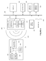
- FIG. 1 is a block diagram of an advantageous embodiment of the present invention.
- FIG. 2 is a block diagram according to the advantageous embodiment of FIG. 1 .
- FIG. 2A is a block diagram according to the advantageous embodiment of FIG. 1 .
- FIG. 3 is a block diagram according to the advantageous embodiment of FIG. 2 .
- FIG. 4 is a block diagram according to the advantageous embodiment of FIG. 2 .
- FIG. 5 is a block diagram according to the advantageous embodiment of FIG. 2 .
- FIG. 6 is a block diagram according to the advantageous embodiment of 1.
- FIG. 1 generally depicts system 100 for providing electrical power to a medical device 102 .
- medical device 102 could comprise virtually any type of powered medical device, including but not limited to, a cutting/cauterizing tool, an irrigation/aspiration tool, a visualization tool, a recording and/or printing device and the like.
- Medical device 102 is provided with electronic circuit 104 and resonant receiver 106 .
- Electronic circuit 104 may comprise any electronic/electrical circuit(s) used to operate medical device 102 .
- Electronic circuit 104 is electrically coupled to resonant receiver 106 .
- power transmitting unit 108 that includes resonant transmitter 110 . It is contemplated that resonant transmitter 110 generates a resonant magnetic field 112 (depicted by the concentric lines) that transmits from power transmitting unit 108 .
- Resonant receiver 106 is “tuned” to the same frequency as resonant magnetic field 112 such that, when resonant receiver 106 is moved to a location within resonant magnetic field 112 , a strong resonant coupling occurs between resonant receiver 106 and resonant transmitter 110 .
- the resonant coupling in one advantageous embodiment, comprises evanescent stationary near-field.
- the transmitter/receiver may comprise virtually any type of resonant structure
- the electromagnetic resonant system may comprise dielectric disks and capacitively-loaded conducting-wire loops. This arrangement provides the advantages of a strong coupling for relatively large and efficient power transfer as well as relatively weak interaction with other off-resonant environmental objects in the vicinity.
- system 200 generally includes an endoscope 202 having an imager 204 , a light source 206 and an endoscope transceiver 208 .
- System 200 further includes control unit 210 having control unit transceiver 212 and processor 214 .
- Display 216 is shown coupled to control unit 210 .
- control unit transceiver 212 generates a resonant magnetic field 218 similar to that described in connection with FIG. 1 and will not be re-described here.
- Endoscope transceiver 208 receives electrical power via resonant magnetic field 218 , which is transmitted to imager 204 and light source 206 for operating the respective devices.
- imager 204 may comprise virtually any type of imaging device, including for example, a CCD or CMOS device for generating image data.
- light source 206 may comprise virtually any type of device for providing illuminating light, such as, for example, an LED.
- the endoscope comprises a shaft 203 , either rigid or flexible, that is inserted into a body cavity on which a medical procedure is to be performed.
- the light source is located in a handle portion of the endoscope and illuminating light is transmitted down a light path to a distal end of the shaft to illuminate an area ahead of the shaft.
- the imager 204 ′ may, alternatively be positioned at the distal end of the shaft 203 to receive or pick up reflected light to generate image data. The image data may then be wirelessly transmitted to the control unit.
- the image data is provided as a video image data stream comprising from about 30 to about 60 frames of data per second. This is possible as the resonant coupling allows for sufficient electrical power to be transmitted to the endoscope transceiver 208 .
- the processor 214 is positioned in control unit 210 and is designed to receive and process the received image data. It is contemplated that the processor 214 may further comprise a configurable unit to process the image data in the format received from the imager 204 .
- the image data is processed into a format compatible for use with display 216 , the image data is transmitted to and displayed on display 216 for observation by a user/viewer.
- endoscope transceiver 208 and control unit transceiver 212 are provided to resonantly couple electrical power from control unit 210 to endoscope 202 for operation of the electronics in endoscope 202 . It is further contemplated that endoscope transceiver is adapted to transmit the image data generated by imager 204 to control unit transceiver 212 for processing by processor 214 . In one advantageous embodiment, the transmission of image data occurs via RF transmission. In another advantageous embodiment, the transmission of image data occurs via the resonant coupling method previously described. In either event, there is two-way transmission (i.e. electrical power to endoscope 202 and image data to control unit 210 ).
- FIG. 2A illustrated another embodiment of the present invention highlighting that the power transmitting unit 108 including the resonant transmitter 110 discussed in connection with FIG. 1 need not be located in a control unit, but may in fact, merely be positioned in the vicinity of the endoscope 202 .
- system 200 is depicted including the endoscope 202 and control unit 210 as per FIG. 2 .
- the function and operation of the various features listed in FIG. 2 are substantially identical and will not be re-described in connection with FIG. 3 .
- power storage device 220 which may comprise, for example, a rechargeable battery. It is contemplated that battery 220 may comprise virtually any type of rechargeable battery as is known in industry. However, power storage device 220 will advantageously be kept relative small and light-weight to keep the weight of endoscope 202 to a minimum.
- power storage device 220 is coupled to the electrical connections between imager 204 and light source 206 and endoscope transceiver 208 , such that, in the event that the resonant coupling between endoscope transceiver 208 and control unit transceiver 212 is lost, power storage device 220 will provide electrical power to both imager 204 and light source 206 . It is still further contemplated that when endoscope transceiver is resonantly coupled to control unit transceiver 212 , power storage device 220 will automatically charge. While an on-board power source is provided in endoscope 202 in this particular embodiment, it should be noted that the power storage device 220 may be provided relative small in size and weight. Accordingly, due to the relatively small and light-weight characteristics of storage device 220 , the endoscope is not designed to indefinitely run on of the power storage device 220 .
- data storage 222 which is coupled to processor 214 . While data storage device is illustrated as residing in control unit 210 , it is contemplated that data storage device may reside anywhere and may include virtually any type of data storage device including, for example, a hard drive device, RAM, ROM, optical storage, a USB thumb drive or the like, which is connected locally or via a network connection (including e.g., the Internet).
- a network connection including e.g., the Internet
- Input device 224 is also shown coupled to control unit 210 .
- Control unit 224 may comprise virtually any type of interface for a user to input commands.
- input device 224 may comprise a keyboard, a control panel, voice activation, a USB device, etc.
- display 216 and input device 224 are illustrated as different devices, it is contemplated that display 216 may comprise a touch screen such that input device and display 216 are embodied in a single device.
- a user may save the image data to data storage 222 .
- a user is able to access the saved image data to be replayed on display 216 .
- the image data that is being displayed on the display during a procedure could be paused, re-wound and re-played for the physician.
- the image data could be annotated by the physician, including for example, a written annotation attached to the file or even an audio or visual annotation to the image data.
- the system 200 further includes a connection to a bus 226 to which are connected a controller 228 and various medical devices ( 230 , 232 ). It is further contemplated that a network connection 234 may be provided such that the system 200 may be accessed via the Internet.
- the configuration illustrated in FIG. 4 is one configuration that is generally known as a “surgical suite.”
- the medical devices may comprise virtually any type of medical device that may be operated by input device 224 and controller 228 including, but not limited to, cutting/cauterizing tool(s), irrigation tool(s), aspiration tool(s), visualization tool(s), recording and/or printing devices, etc.
- the surgical suite may be a rack mounted arrangement that may be portable from one surgical room to the next.
- FIG. 5 is provided to illustrate some of the communications that occur between endoscope 202 and control unit 210 .
- endoscope 202 is brought within the resonant magnetic field emanating from control unit 210 , resonant coupling occurs between the endoscope transceiver 208 and control unit transceiver 212 such that electrical power is transmitted 236 to endoscope 202 .
- endoscope 202 Once endoscope 202 is powered up, information is transmitted over a data channel 244 identification data is transmitted to control unit 210 that identifies the type and settings of endoscope 202 . Control unit 210 then adjusts its internal settings so as to be able to properly receive the image data from endoscope 202 . Once configured, control unit 210 may then send command/control data 240 to endoscope for operating endoscope 202 . Endoscope 202 will then begin transmitting a video image data stream 242 to control unit 210 for processing and display.
- FIG. 6 is still another embodiment of the present invention similar to that described in connection with FIG. 2 , however, also included are camera 250 , coupling 252 and coupling 254 .
- FIG. 6 is designed for an endoscope 202 with a detachable camera 250 , where the camera may already have an independent connection (coupling 254 ) to the control unit 210 .
- Coupling 254 may comprise a hard-wired connection or a wireless connection for the transmission of both power and/or data. This could allow for the use of existing cameras with endoscope having the transceiver arrangement where only the endoscope receives power via resonant magnetic field 218 .
- coupling 252 may comprise a connection that allows for the transmission of reflected light received by the endoscope to be transmitted to the camera 250 .
- the imager 204 may be positioned in the endoscope and the camera 250 receives a data stream via coupling 252 .
- power may be transmitted to both the endoscope and camera via resonant magnetic field 218 while data may be transmitted between camera 250 and control unit 210 via coupling 254 .
- the data transmitted via coupling 254 may include, for example, the video data stream, control and command data.
- the video data stream the video data stream is wirelessly transmitted on a data channel via resonant magnetic field 218 while that control and command data are transmitted between camera 250 and control unit 210 via coupling 254 and vice versa.
- the endoscope may be provided as a direct visualization endoscope where camera or video functionality may or may not be provided.
Abstract
Description
Claims (37)
Priority Applications (6)
| Application Number | Priority Date | Filing Date | Title |
|---|---|---|---|
| US12/425,869 US9526407B2 (en) | 2008-04-25 | 2009-04-17 | Wirelessly powered medical devices and instruments |
| JP2011506296A JP5419964B2 (en) | 2008-04-25 | 2009-04-23 | Medical device system powered by wireless |
| CA2725413A CA2725413C (en) | 2008-04-25 | 2009-04-23 | Wirelessly powered medical devices and instruments |
| PCT/US2009/002518 WO2009131691A1 (en) | 2008-04-25 | 2009-04-23 | Wirelessly powered medical devices and instruments |
| EP09734033.5A EP2276389B1 (en) | 2008-04-25 | 2009-04-23 | Wirelessly powered medical devices and instruments |
| US12/545,567 US9603512B2 (en) | 2008-04-25 | 2009-08-21 | Wirelessly powered medical devices and instruments |
Applications Claiming Priority (2)
| Application Number | Priority Date | Filing Date | Title |
|---|---|---|---|
| US4796708P | 2008-04-25 | 2008-04-25 | |
| US12/425,869 US9526407B2 (en) | 2008-04-25 | 2009-04-17 | Wirelessly powered medical devices and instruments |
Related Child Applications (1)
| Application Number | Title | Priority Date | Filing Date |
|---|---|---|---|
| US12/545,567 Continuation-In-Part US9603512B2 (en) | 2008-04-25 | 2009-08-21 | Wirelessly powered medical devices and instruments |
Publications (2)
| Publication Number | Publication Date |
|---|---|
| US20090270679A1 US20090270679A1 (en) | 2009-10-29 |
| US9526407B2 true US9526407B2 (en) | 2016-12-27 |
Family
ID=41215639
Family Applications (1)
| Application Number | Title | Priority Date | Filing Date |
|---|---|---|---|
| US12/425,869 Active 2033-05-26 US9526407B2 (en) | 2008-04-25 | 2009-04-17 | Wirelessly powered medical devices and instruments |
Country Status (5)
| Country | Link |
|---|---|
| US (1) | US9526407B2 (en) |
| EP (1) | EP2276389B1 (en) |
| JP (1) | JP5419964B2 (en) |
| CA (1) | CA2725413C (en) |
| WO (1) | WO2009131691A1 (en) |
Cited By (128)
| Publication number | Priority date | Publication date | Assignee | Title |
|---|---|---|---|---|
| US10595887B2 (en) | 2017-12-28 | 2020-03-24 | Ethicon Llc | Systems for adjusting end effector parameters based on perioperative information |
| US10695081B2 (en) | 2017-12-28 | 2020-06-30 | Ethicon Llc | Controlling a surgical instrument according to sensed closure parameters |
| US10755813B2 (en) | 2017-12-28 | 2020-08-25 | Ethicon Llc | Communication of smoke evacuation system parameters to hub or cloud in smoke evacuation module for interactive surgical platform |
| US10758310B2 (en) | 2017-12-28 | 2020-09-01 | Ethicon Llc | Wireless pairing of a surgical device with another device within a sterile surgical field based on the usage and situational awareness of devices |
| US10772651B2 (en) | 2017-10-30 | 2020-09-15 | Ethicon Llc | Surgical instruments comprising a system for articulation and rotation compensation |
| US10849697B2 (en) | 2017-12-28 | 2020-12-01 | Ethicon Llc | Cloud interface for coupled surgical devices |
| WO2020260999A1 (en) | 2019-06-27 | 2020-12-30 | Ethicon Llc | Robotic surgical system with safety and cooperative sensing control |
| US10892899B2 (en) | 2017-12-28 | 2021-01-12 | Ethicon Llc | Self describing data packets generated at an issuing instrument |
| US10892995B2 (en) | 2017-12-28 | 2021-01-12 | Ethicon Llc | Surgical network determination of prioritization of communication, interaction, or processing based on system or device needs |
| US10898622B2 (en) | 2017-12-28 | 2021-01-26 | Ethicon Llc | Surgical evacuation system with a communication circuit for communication between a filter and a smoke evacuation device |
| US10932872B2 (en) | 2017-12-28 | 2021-03-02 | Ethicon Llc | Cloud-based medical analytics for linking of local usage trends with the resource acquisition behaviors of larger data set |
| US10943454B2 (en) | 2017-12-28 | 2021-03-09 | Ethicon Llc | Detection and escalation of security responses of surgical instruments to increasing severity threats |
| US10944728B2 (en) | 2017-12-28 | 2021-03-09 | Ethicon Llc | Interactive surgical systems with encrypted communication capabilities |
| US10966791B2 (en) | 2017-12-28 | 2021-04-06 | Ethicon Llc | Cloud-based medical analytics for medical facility segmented individualization of instrument function |
| US10973520B2 (en) | 2018-03-28 | 2021-04-13 | Ethicon Llc | Surgical staple cartridge with firing member driven camming assembly that has an onboard tissue cutting feature |
| US10987178B2 (en) | 2017-12-28 | 2021-04-27 | Ethicon Llc | Surgical hub control arrangements |
| US11013563B2 (en) | 2017-12-28 | 2021-05-25 | Ethicon Llc | Drive arrangements for robot-assisted surgical platforms |
| US11026751B2 (en) | 2017-12-28 | 2021-06-08 | Cilag Gmbh International | Display of alignment of staple cartridge to prior linear staple line |
| US11026687B2 (en) | 2017-10-30 | 2021-06-08 | Cilag Gmbh International | Clip applier comprising clip advancing systems |
| US11051876B2 (en) | 2017-12-28 | 2021-07-06 | Cilag Gmbh International | Surgical evacuation flow paths |
| US11056244B2 (en) | 2017-12-28 | 2021-07-06 | Cilag Gmbh International | Automated data scaling, alignment, and organizing based on predefined parameters within surgical networks |
| US11058498B2 (en) | 2017-12-28 | 2021-07-13 | Cilag Gmbh International | Cooperative surgical actions for robot-assisted surgical platforms |
| US11069012B2 (en) | 2017-12-28 | 2021-07-20 | Cilag Gmbh International | Interactive surgical systems with condition handling of devices and data capabilities |
| US11076921B2 (en) | 2017-12-28 | 2021-08-03 | Cilag Gmbh International | Adaptive control program updates for surgical hubs |
| US11090047B2 (en) | 2018-03-28 | 2021-08-17 | Cilag Gmbh International | Surgical instrument comprising an adaptive control system |
| US11100631B2 (en) | 2017-12-28 | 2021-08-24 | Cilag Gmbh International | Use of laser light and red-green-blue coloration to determine properties of back scattered light |
| US11096688B2 (en) | 2018-03-28 | 2021-08-24 | Cilag Gmbh International | Rotary driven firing members with different anvil and channel engagement features |
| US11096693B2 (en) | 2017-12-28 | 2021-08-24 | Cilag Gmbh International | Adjustment of staple height of at least one row of staples based on the sensed tissue thickness or force in closing |
| US11109866B2 (en) | 2017-12-28 | 2021-09-07 | Cilag Gmbh International | Method for circular stapler control algorithm adjustment based on situational awareness |
| US11114195B2 (en) | 2017-12-28 | 2021-09-07 | Cilag Gmbh International | Surgical instrument with a tissue marking assembly |
| US11129611B2 (en) | 2018-03-28 | 2021-09-28 | Cilag Gmbh International | Surgical staplers with arrangements for maintaining a firing member thereof in a locked configuration unless a compatible cartridge has been installed therein |
| US11132462B2 (en) | 2017-12-28 | 2021-09-28 | Cilag Gmbh International | Data stripping method to interrogate patient records and create anonymized record |
| US11147607B2 (en) | 2017-12-28 | 2021-10-19 | Cilag Gmbh International | Bipolar combination device that automatically adjusts pressure based on energy modality |
| US11160605B2 (en) | 2017-12-28 | 2021-11-02 | Cilag Gmbh International | Surgical evacuation sensing and motor control |
| US11166772B2 (en) | 2017-12-28 | 2021-11-09 | Cilag Gmbh International | Surgical hub coordination of control and communication of operating room devices |
| US11179208B2 (en) | 2017-12-28 | 2021-11-23 | Cilag Gmbh International | Cloud-based medical analytics for security and authentication trends and reactive measures |
| US11179175B2 (en) | 2017-12-28 | 2021-11-23 | Cilag Gmbh International | Controlling an ultrasonic surgical instrument according to tissue location |
| US11202570B2 (en) | 2017-12-28 | 2021-12-21 | Cilag Gmbh International | Communication hub and storage device for storing parameters and status of a surgical device to be shared with cloud based analytics systems |
| US11207067B2 (en) | 2018-03-28 | 2021-12-28 | Cilag Gmbh International | Surgical stapling device with separate rotary driven closure and firing systems and firing member that engages both jaws while firing |
| US11219453B2 (en) | 2018-03-28 | 2022-01-11 | Cilag Gmbh International | Surgical stapling devices with cartridge compatible closure and firing lockout arrangements |
| US11229436B2 (en) | 2017-10-30 | 2022-01-25 | Cilag Gmbh International | Surgical system comprising a surgical tool and a surgical hub |
| US11234756B2 (en) | 2017-12-28 | 2022-02-01 | Cilag Gmbh International | Powered surgical tool with predefined adjustable control algorithm for controlling end effector parameter |
| US11253315B2 (en) | 2017-12-28 | 2022-02-22 | Cilag Gmbh International | Increasing radio frequency to create pad-less monopolar loop |
| US11257589B2 (en) | 2017-12-28 | 2022-02-22 | Cilag Gmbh International | Real-time analysis of comprehensive cost of all instrumentation used in surgery utilizing data fluidity to track instruments through stocking and in-house processes |
| US11259806B2 (en) | 2018-03-28 | 2022-03-01 | Cilag Gmbh International | Surgical stapling devices with features for blocking advancement of a camming assembly of an incompatible cartridge installed therein |
| US11259830B2 (en) | 2018-03-08 | 2022-03-01 | Cilag Gmbh International | Methods for controlling temperature in ultrasonic device |
| US11259807B2 (en) | 2019-02-19 | 2022-03-01 | Cilag Gmbh International | Staple cartridges with cam surfaces configured to engage primary and secondary portions of a lockout of a surgical stapling device |
| US11266468B2 (en) | 2017-12-28 | 2022-03-08 | Cilag Gmbh International | Cooperative utilization of data derived from secondary sources by intelligent surgical hubs |
| US11273001B2 (en) | 2017-12-28 | 2022-03-15 | Cilag Gmbh International | Surgical hub and modular device response adjustment based on situational awareness |
| US11278280B2 (en) | 2018-03-28 | 2022-03-22 | Cilag Gmbh International | Surgical instrument comprising a jaw closure lockout |
| US11278281B2 (en) | 2017-12-28 | 2022-03-22 | Cilag Gmbh International | Interactive surgical system |
| US11284936B2 (en) | 2017-12-28 | 2022-03-29 | Cilag Gmbh International | Surgical instrument having a flexible electrode |
| US11291510B2 (en) | 2017-10-30 | 2022-04-05 | Cilag Gmbh International | Method of hub communication with surgical instrument systems |
| US11291495B2 (en) | 2017-12-28 | 2022-04-05 | Cilag Gmbh International | Interruption of energy due to inadvertent capacitive coupling |
| US11298148B2 (en) | 2018-03-08 | 2022-04-12 | Cilag Gmbh International | Live time tissue classification using electrical parameters |
| US11304745B2 (en) | 2017-12-28 | 2022-04-19 | Cilag Gmbh International | Surgical evacuation sensing and display |
| US11304720B2 (en) | 2017-12-28 | 2022-04-19 | Cilag Gmbh International | Activation of energy devices |
| US11304699B2 (en) | 2017-12-28 | 2022-04-19 | Cilag Gmbh International | Method for adaptive control schemes for surgical network control and interaction |
| US11304763B2 (en) | 2017-12-28 | 2022-04-19 | Cilag Gmbh International | Image capturing of the areas outside the abdomen to improve placement and control of a surgical device in use |
| US11308075B2 (en) | 2017-12-28 | 2022-04-19 | Cilag Gmbh International | Surgical network, instrument, and cloud responses based on validation of received dataset and authentication of its source and integrity |
| US11311342B2 (en) | 2017-10-30 | 2022-04-26 | Cilag Gmbh International | Method for communicating with surgical instrument systems |
| US11311306B2 (en) | 2017-12-28 | 2022-04-26 | Cilag Gmbh International | Surgical systems for detecting end effector tissue distribution irregularities |
| US11317937B2 (en) | 2018-03-08 | 2022-05-03 | Cilag Gmbh International | Determining the state of an ultrasonic end effector |
| USD950728S1 (en) | 2019-06-25 | 2022-05-03 | Cilag Gmbh International | Surgical staple cartridge |
| US11317915B2 (en) | 2019-02-19 | 2022-05-03 | Cilag Gmbh International | Universal cartridge based key feature that unlocks multiple lockout arrangements in different surgical staplers |
| US11317919B2 (en) | 2017-10-30 | 2022-05-03 | Cilag Gmbh International | Clip applier comprising a clip crimping system |
| US11324557B2 (en) | 2017-12-28 | 2022-05-10 | Cilag Gmbh International | Surgical instrument with a sensing array |
| USD952144S1 (en) | 2019-06-25 | 2022-05-17 | Cilag Gmbh International | Surgical staple cartridge retainer with firing system authentication key |
| US11337746B2 (en) | 2018-03-08 | 2022-05-24 | Cilag Gmbh International | Smart blade and power pulsing |
| US11357503B2 (en) | 2019-02-19 | 2022-06-14 | Cilag Gmbh International | Staple cartridge retainers with frangible retention features and methods of using same |
| US11364075B2 (en) | 2017-12-28 | 2022-06-21 | Cilag Gmbh International | Radio frequency energy device for delivering combined electrical signals |
| US11369443B2 (en) | 2019-06-27 | 2022-06-28 | Cilag Gmbh International | Method of using a surgical modular robotic assembly |
| US11369377B2 (en) | 2019-02-19 | 2022-06-28 | Cilag Gmbh International | Surgical stapling assembly with cartridge based retainer configured to unlock a firing lockout |
| US11376002B2 (en) | 2017-12-28 | 2022-07-05 | Cilag Gmbh International | Surgical instrument cartridge sensor assemblies |
| US11376083B2 (en) | 2019-06-27 | 2022-07-05 | Cilag Gmbh International | Determining robotic surgical assembly coupling status |
| US11389164B2 (en) | 2017-12-28 | 2022-07-19 | Cilag Gmbh International | Method of using reinforced flexible circuits with multiple sensors to optimize performance of radio frequency devices |
| US11399906B2 (en) | 2019-06-27 | 2022-08-02 | Cilag Gmbh International | Robotic surgical system for controlling close operation of end-effectors |
| US11410259B2 (en) | 2017-12-28 | 2022-08-09 | Cilag Gmbh International | Adaptive control program updates for surgical devices |
| US11413102B2 (en) | 2019-06-27 | 2022-08-16 | Cilag Gmbh International | Multi-access port for surgical robotic systems |
| US11423007B2 (en) | 2017-12-28 | 2022-08-23 | Cilag Gmbh International | Adjustment of device control programs based on stratified contextual data in addition to the data |
| US11424027B2 (en) | 2017-12-28 | 2022-08-23 | Cilag Gmbh International | Method for operating surgical instrument systems |
| US11419630B2 (en) | 2017-12-28 | 2022-08-23 | Cilag Gmbh International | Surgical system distributed processing |
| US11419667B2 (en) | 2017-12-28 | 2022-08-23 | Cilag Gmbh International | Ultrasonic energy device which varies pressure applied by clamp arm to provide threshold control pressure at a cut progression location |
| US11432885B2 (en) | 2017-12-28 | 2022-09-06 | Cilag Gmbh International | Sensing arrangements for robot-assisted surgical platforms |
| USD964564S1 (en) | 2019-06-25 | 2022-09-20 | Cilag Gmbh International | Surgical staple cartridge retainer with a closure system authentication key |
| US11446052B2 (en) | 2017-12-28 | 2022-09-20 | Cilag Gmbh International | Variation of radio frequency and ultrasonic power level in cooperation with varying clamp arm pressure to achieve predefined heat flux or power applied to tissue |
| US11464559B2 (en) | 2017-12-28 | 2022-10-11 | Cilag Gmbh International | Estimating state of ultrasonic end effector and control system therefor |
| US11464511B2 (en) | 2019-02-19 | 2022-10-11 | Cilag Gmbh International | Surgical staple cartridges with movable authentication key arrangements |
| US11464535B2 (en) | 2017-12-28 | 2022-10-11 | Cilag Gmbh International | Detection of end effector emersion in liquid |
| US11471156B2 (en) | 2018-03-28 | 2022-10-18 | Cilag Gmbh International | Surgical stapling devices with improved rotary driven closure systems |
| US11504192B2 (en) | 2014-10-30 | 2022-11-22 | Cilag Gmbh International | Method of hub communication with surgical instrument systems |
| US11510741B2 (en) | 2017-10-30 | 2022-11-29 | Cilag Gmbh International | Method for producing a surgical instrument comprising a smart electrical system |
| US11529187B2 (en) | 2017-12-28 | 2022-12-20 | Cilag Gmbh International | Surgical evacuation sensor arrangements |
| US11540855B2 (en) | 2017-12-28 | 2023-01-03 | Cilag Gmbh International | Controlling activation of an ultrasonic surgical instrument according to the presence of tissue |
| US11547465B2 (en) | 2012-06-28 | 2023-01-10 | Cilag Gmbh International | Surgical end effector jaw and electrode configurations |
| US11547468B2 (en) | 2019-06-27 | 2023-01-10 | Cilag Gmbh International | Robotic surgical system with safety and cooperative sensing control |
| US11559308B2 (en) | 2017-12-28 | 2023-01-24 | Cilag Gmbh International | Method for smart energy device infrastructure |
| US11559307B2 (en) | 2017-12-28 | 2023-01-24 | Cilag Gmbh International | Method of robotic hub communication, detection, and control |
| US11564756B2 (en) | 2017-10-30 | 2023-01-31 | Cilag Gmbh International | Method of hub communication with surgical instrument systems |
| US11571234B2 (en) | 2017-12-28 | 2023-02-07 | Cilag Gmbh International | Temperature control of ultrasonic end effector and control system therefor |
| US11576677B2 (en) | 2017-12-28 | 2023-02-14 | Cilag Gmbh International | Method of hub communication, processing, display, and cloud analytics |
| US11589888B2 (en) | 2017-12-28 | 2023-02-28 | Cilag Gmbh International | Method for controlling smart energy devices |
| US11589932B2 (en) | 2017-12-28 | 2023-02-28 | Cilag Gmbh International | Usage and technique analysis of surgeon / staff performance against a baseline to optimize device utilization and performance for both current and future procedures |
| US11596291B2 (en) | 2017-12-28 | 2023-03-07 | Cilag Gmbh International | Method of compressing tissue within a stapling device and simultaneously displaying of the location of the tissue within the jaws |
| US11602393B2 (en) | 2017-12-28 | 2023-03-14 | Cilag Gmbh International | Surgical evacuation sensing and generator control |
| US11607278B2 (en) | 2019-06-27 | 2023-03-21 | Cilag Gmbh International | Cooperative robotic surgical systems |
| US11612445B2 (en) | 2019-06-27 | 2023-03-28 | Cilag Gmbh International | Cooperative operation of robotic arms |
| US11612444B2 (en) | 2017-12-28 | 2023-03-28 | Cilag Gmbh International | Adjustment of a surgical device function based on situational awareness |
| US11659023B2 (en) | 2017-12-28 | 2023-05-23 | Cilag Gmbh International | Method of hub communication |
| US11666331B2 (en) | 2017-12-28 | 2023-06-06 | Cilag Gmbh International | Systems for detecting proximity of surgical end effector to cancerous tissue |
| US11723729B2 (en) | 2019-06-27 | 2023-08-15 | Cilag Gmbh International | Robotic surgical assembly coupling safety mechanisms |
| US11744604B2 (en) | 2017-12-28 | 2023-09-05 | Cilag Gmbh International | Surgical instrument with a hardware-only control circuit |
| US11771487B2 (en) | 2017-12-28 | 2023-10-03 | Cilag Gmbh International | Mechanisms for controlling different electromechanical systems of an electrosurgical instrument |
| US11786251B2 (en) | 2017-12-28 | 2023-10-17 | Cilag Gmbh International | Method for adaptive control schemes for surgical network control and interaction |
| US11786245B2 (en) | 2017-12-28 | 2023-10-17 | Cilag Gmbh International | Surgical systems with prioritized data transmission capabilities |
| US11801098B2 (en) | 2017-10-30 | 2023-10-31 | Cilag Gmbh International | Method of hub communication with surgical instrument systems |
| US11818052B2 (en) | 2017-12-28 | 2023-11-14 | Cilag Gmbh International | Surgical network determination of prioritization of communication, interaction, or processing based on system or device needs |
| US11832899B2 (en) | 2017-12-28 | 2023-12-05 | Cilag Gmbh International | Surgical systems with autonomously adjustable control programs |
| US11832840B2 (en) | 2017-12-28 | 2023-12-05 | Cilag Gmbh International | Surgical instrument having a flexible circuit |
| US11857152B2 (en) | 2017-12-28 | 2024-01-02 | Cilag Gmbh International | Surgical hub spatial awareness to determine devices in operating theater |
| US11864728B2 (en) | 2017-12-28 | 2024-01-09 | Cilag Gmbh International | Characterization of tissue irregularities through the use of mono-chromatic light refractivity |
| US11871901B2 (en) | 2012-05-20 | 2024-01-16 | Cilag Gmbh International | Method for situational awareness for surgical network or surgical network connected device capable of adjusting function based on a sensed situation or usage |
| US11896322B2 (en) | 2017-12-28 | 2024-02-13 | Cilag Gmbh International | Sensing the patient position and contact utilizing the mono-polar return pad electrode to provide situational awareness to the hub |
| US11896443B2 (en) | 2017-12-28 | 2024-02-13 | Cilag Gmbh International | Control of a surgical system through a surgical barrier |
| US11903601B2 (en) | 2017-12-28 | 2024-02-20 | Cilag Gmbh International | Surgical instrument comprising a plurality of drive systems |
| US11911045B2 (en) | 2017-10-30 | 2024-02-27 | Cllag GmbH International | Method for operating a powered articulating multi-clip applier |
| US11931026B2 (en) | 2021-06-30 | 2024-03-19 | Cilag Gmbh International | Staple cartridge replacement |
| US11937769B2 (en) | 2017-12-28 | 2024-03-26 | Cilag Gmbh International | Method of hub communication, processing, storage and display |
Families Citing this family (63)
| Publication number | Priority date | Publication date | Assignee | Title |
|---|---|---|---|---|
| US8599250B2 (en) * | 2002-03-12 | 2013-12-03 | Karl Storz Imaging, Inc. | Wireless camera coupling |
| US9138207B2 (en) * | 2009-05-19 | 2015-09-22 | Teleflex Medical Incorporated | Methods and devices for laparoscopic surgery |
| US9713417B2 (en) | 2009-06-18 | 2017-07-25 | Endochoice, Inc. | Image capture assembly for use in a multi-viewing elements endoscope |
| US9101268B2 (en) | 2009-06-18 | 2015-08-11 | Endochoice Innovation Center Ltd. | Multi-camera endoscope |
| US11864734B2 (en) | 2009-06-18 | 2024-01-09 | Endochoice, Inc. | Multi-camera endoscope |
| US8926502B2 (en) | 2011-03-07 | 2015-01-06 | Endochoice, Inc. | Multi camera endoscope having a side service channel |
| US9492063B2 (en) | 2009-06-18 | 2016-11-15 | Endochoice Innovation Center Ltd. | Multi-viewing element endoscope |
| US11547275B2 (en) | 2009-06-18 | 2023-01-10 | Endochoice, Inc. | Compact multi-viewing element endoscope system |
| US9554692B2 (en) | 2009-06-18 | 2017-01-31 | EndoChoice Innovation Ctr. Ltd. | Multi-camera endoscope |
| US9642513B2 (en) | 2009-06-18 | 2017-05-09 | Endochoice Inc. | Compact multi-viewing element endoscope system |
| WO2012038958A2 (en) | 2010-09-20 | 2012-03-29 | Peermedical Ltd. | Multi-camera endoscope having fluid channels |
| WO2012120507A1 (en) | 2011-02-07 | 2012-09-13 | Peermedical Ltd. | Multi-element cover for a multi-camera endoscope |
| US9872609B2 (en) | 2009-06-18 | 2018-01-23 | Endochoice Innovation Center Ltd. | Multi-camera endoscope |
| US9402533B2 (en) | 2011-03-07 | 2016-08-02 | Endochoice Innovation Center Ltd. | Endoscope circuit board assembly |
| US11278190B2 (en) | 2009-06-18 | 2022-03-22 | Endochoice, Inc. | Multi-viewing element endoscope |
| US10165929B2 (en) | 2009-06-18 | 2019-01-01 | Endochoice, Inc. | Compact multi-viewing element endoscope system |
| US9901244B2 (en) | 2009-06-18 | 2018-02-27 | Endochoice, Inc. | Circuit board assembly of a multiple viewing elements endoscope |
| US9101287B2 (en) | 2011-03-07 | 2015-08-11 | Endochoice Innovation Center Ltd. | Multi camera endoscope assembly having multiple working channels |
| US9706903B2 (en) | 2009-06-18 | 2017-07-18 | Endochoice, Inc. | Multiple viewing elements endoscope system with modular imaging units |
| US10052088B2 (en) | 2010-01-20 | 2018-08-21 | EON Surgical Ltd. | System and method of deploying an elongate unit in a body cavity |
| BR112013006650A2 (en) | 2010-09-19 | 2017-07-18 | Eon Surgical Ltd | microlaparoscopy devices and positions of these |
| US9560953B2 (en) | 2010-09-20 | 2017-02-07 | Endochoice, Inc. | Operational interface in a multi-viewing element endoscope |
| EP2624879B1 (en) * | 2010-10-07 | 2017-05-10 | Everheart Systems, Inc. | Cardiac support systems and methods for chronic use |
| US9227001B2 (en) | 2010-10-07 | 2016-01-05 | Everheart Systems Inc. | High efficiency blood pump |
| US8551163B2 (en) | 2010-10-07 | 2013-10-08 | Everheart Systems Inc. | Cardiac support systems and methods for chronic use |
| CN103403605A (en) | 2010-10-28 | 2013-11-20 | 恩多巧爱思创新中心有限公司 | Optical systems for multi-sensor endoscopes |
| EP2648602B1 (en) | 2010-12-09 | 2018-07-18 | EndoChoice Innovation Center Ltd. | Flexible electronic circuit board multi-camera endoscope |
| US11889986B2 (en) | 2010-12-09 | 2024-02-06 | Endochoice, Inc. | Flexible electronic circuit board for a multi-camera endoscope |
| US9814374B2 (en) | 2010-12-09 | 2017-11-14 | Endochoice Innovation Center Ltd. | Flexible electronic circuit board for a multi-camera endoscope |
| US9496924B2 (en) | 2010-12-10 | 2016-11-15 | Everheart Systems, Inc. | Mobile wireless power system |
| EP2604175B1 (en) | 2011-12-13 | 2019-11-20 | EndoChoice Innovation Center Ltd. | Removable tip endoscope |
| EP2604172B1 (en) | 2011-12-13 | 2015-08-12 | EndoChoice Innovation Center Ltd. | Rotatable connector for an endoscope |
| US9560954B2 (en) | 2012-07-24 | 2017-02-07 | Endochoice, Inc. | Connector for use with endoscope |
| WO2014018967A1 (en) | 2012-07-27 | 2014-01-30 | Thoratec Corporation | Self-tuning resonant power transfer systems |
| US10525181B2 (en) | 2012-07-27 | 2020-01-07 | Tc1 Llc | Resonant power transfer system and method of estimating system state |
| US10251987B2 (en) | 2012-07-27 | 2019-04-09 | Tc1 Llc | Resonant power transmission coils and systems |
| US9805863B2 (en) | 2012-07-27 | 2017-10-31 | Thoratec Corporation | Magnetic power transmission utilizing phased transmitter coil arrays and phased receiver coil arrays |
| EP4257174A3 (en) | 2012-07-27 | 2023-12-27 | Tc1 Llc | Thermal management for implantable wireless power transfer systems |
| US9825471B2 (en) | 2012-07-27 | 2017-11-21 | Thoratec Corporation | Resonant power transfer systems with protective algorithm |
| WO2014018972A1 (en) | 2012-07-27 | 2014-01-30 | Thoratec Corporation | Computer modeling for resonant power transfer systems |
| US10383990B2 (en) | 2012-07-27 | 2019-08-20 | Tc1 Llc | Variable capacitor for resonant power transfer systems |
| US10294944B2 (en) | 2013-03-08 | 2019-05-21 | Everheart Systems Inc. | Flow thru mechanical blood pump bearings |
| US9680310B2 (en) | 2013-03-15 | 2017-06-13 | Thoratec Corporation | Integrated implantable TETS housing including fins and coil loops |
| EP2984731B8 (en) | 2013-03-15 | 2019-06-26 | Tc1 Llc | Malleable tets coil with improved anatomical fit |
| US9986899B2 (en) | 2013-03-28 | 2018-06-05 | Endochoice, Inc. | Manifold for a multiple viewing elements endoscope |
| US9993142B2 (en) | 2013-03-28 | 2018-06-12 | Endochoice, Inc. | Fluid distribution device for a multiple viewing elements endoscope |
| US10499794B2 (en) | 2013-05-09 | 2019-12-10 | Endochoice, Inc. | Operational interface in a multi-viewing element endoscope |
| IN2013DE01670A (en) * | 2013-06-03 | 2015-06-26 | Samhotra Navneet | |
| JP6120963B2 (en) * | 2013-06-28 | 2017-04-26 | オリンパス株式会社 | Endoscope system |
| JP6521992B2 (en) | 2013-11-11 | 2019-05-29 | ティーシー1 エルエルシー | Resonance power transmission system having communication |
| EP3072210B1 (en) | 2013-11-11 | 2023-12-20 | Tc1 Llc | Resonant power transfer systems with communications |
| EP3069358B1 (en) | 2013-11-11 | 2019-06-12 | Tc1 Llc | Hinged resonant power transfer coil |
| WO2015134871A1 (en) | 2014-03-06 | 2015-09-11 | Thoratec Corporation | Electrical connectors for implantable devices |
| JP6655071B2 (en) | 2014-09-22 | 2020-02-26 | ティーシー1 エルエルシー | Antenna design for communicating between wirelessly powered implants and external devices outside the body |
| KR101649545B1 (en) * | 2014-10-01 | 2016-08-22 | 한국과학기술원 | Apparatus for Transfering Wireless Power for Orthopedic Tool and Orthopedic Apparatus Using Same |
| EP3204989B1 (en) | 2014-10-06 | 2019-08-21 | Tc1 Llc | Multiaxial connector for implantable devices |
| CN107205611A (en) * | 2014-11-18 | 2017-09-26 | 史密夫和内修有限公司 | With intercoupler inductively |
| US10148126B2 (en) | 2015-08-31 | 2018-12-04 | Tc1 Llc | Wireless energy transfer system and wearables |
| EP3360233B1 (en) | 2015-10-07 | 2021-08-04 | Tc1 Llc | Resonant power transfer systems having efficiency optimization based on receiver impedance |
| EP3497775B1 (en) | 2016-09-21 | 2022-07-13 | Tc1 Llc | Systems and methods for locating implanted wireless power transmission devices |
| US11197990B2 (en) | 2017-01-18 | 2021-12-14 | Tc1 Llc | Systems and methods for transcutaneous power transfer using microneedles |
| WO2019135890A1 (en) | 2018-01-04 | 2019-07-11 | Tc1 Llc | Systems and methods for elastic wireless power transmission devices |
| KR102404768B1 (en) * | 2020-08-05 | 2022-06-03 | 주식회사 밀알 | Laparoscopic surgery endoscopic module with coating layer applied |
Citations (46)
| Publication number | Priority date | Publication date | Assignee | Title |
|---|---|---|---|---|
| US1119732A (en) | 1907-05-04 | 1914-12-01 | Nikola Tesla | Apparatus for transmitting electrical energy. |
| JPH11309156A (en) | 1998-04-27 | 1999-11-09 | Olympus Optical Co Ltd | Smoke exhauster |
| US6092722A (en) * | 1996-07-23 | 2000-07-25 | Richard Wolf Gmbh | Method and device for the automatic identification of components of medical apparatus systems |
| US6184651B1 (en) | 2000-03-20 | 2001-02-06 | Motorola, Inc. | Contactless battery charger with wireless control link |
| JP2001251611A (en) * | 2000-03-03 | 2001-09-14 | Asahi Optical Co Ltd | Wireless vide camera for endoscope |
| US20020118004A1 (en) * | 1999-06-11 | 2002-08-29 | Guntram Scheible | System for wirelessly supplying a large number of actuators of a machine with electrical power |
| US6569163B2 (en) * | 2001-03-09 | 2003-05-27 | Quantumcor, Inc. | Wireless electrosurgical adapter unit and methods thereof |
| US20030174205A1 (en) | 2002-03-12 | 2003-09-18 | Amling Marc R. | Endoscope reader |
| JP2004113805A (en) | 2003-10-07 | 2004-04-15 | Olympus Corp | Control method for surgery system |
| US20040236193A1 (en) * | 2001-06-05 | 2004-11-25 | Yehuda Sharf | Birth monitoring system |
| JP2005052363A (en) | 2003-08-04 | 2005-03-03 | Olympus Corp | Wireless type information inside subject acquisition system |
| US20050065407A1 (en) * | 2003-09-18 | 2005-03-24 | Olympus Corporation | Energy supplying coil and capsule endoscope system |
| US20050064815A1 (en) * | 2003-07-18 | 2005-03-24 | Pentax Corporation | Capsule-type device and capsule-type device controlling system |
| US20050080318A1 (en) | 2003-10-09 | 2005-04-14 | Squicciarini John B. | Multi-functional video scope |
| US20050080342A1 (en) * | 2001-01-11 | 2005-04-14 | Gilreath Mark G. | Device and system for in-vivo procedures |
| US20050154294A1 (en) * | 2003-10-27 | 2005-07-14 | Olympus Corporation | Capsule medical apparatus |
| US20050177024A1 (en) | 2004-02-10 | 2005-08-11 | Mackin Robert A. | Endotracheal camera |
| JP2005287150A (en) | 2004-03-29 | 2005-10-13 | Olympus Corp | Power supply device |
| JP2006061628A (en) | 2004-08-30 | 2006-03-09 | Olympus Corp | Data generating device, data browse system, data generation method, and data generating program |
| US7042196B2 (en) | 2002-05-13 | 2006-05-09 | Splashpower Limited | Contact-less power transfer |
| US20060173245A1 (en) | 2005-01-28 | 2006-08-03 | Stryker Corporation | Disposable attachable light source unit for an endoscope |
| US20060173259A1 (en) | 2004-10-04 | 2006-08-03 | Flaherty J C | Biological interface system |
| WO2006103778A1 (en) * | 2005-03-30 | 2006-10-05 | Olympus Corporation | Wireless device for acquiring information on inside of subject and wireless system for acquiring information on inside of subject |
| US20060293563A1 (en) | 2001-10-05 | 2006-12-28 | Banik Michael S | Robotic endoscope with wireless interface |
| WO2007008646A2 (en) | 2005-07-12 | 2007-01-18 | Massachusetts Institute Of Technology | Wireless non-radiative energy transfer |
| US20070030345A1 (en) | 2002-03-12 | 2007-02-08 | Karl Storz Imaging, Inc. | Universal scope reader |
| US20070066866A1 (en) * | 2004-04-21 | 2007-03-22 | Toshiaki Noguchi | Medical bed |
| US20070112247A1 (en) | 2005-11-16 | 2007-05-17 | Yasuo Hirata | Endoscope |
| US20070185550A1 (en) | 2005-01-19 | 2007-08-09 | Cardiac Pacemakers, Inc. | Dynamic channel selection for rf telemetry with implantable device |
| WO2007111309A1 (en) | 2006-03-24 | 2007-10-04 | Olympus Corporation | Reception device |
| US20070282165A1 (en) | 2006-05-31 | 2007-12-06 | Karl Storz Endovision | Optically coupled endoscope with microchip |
| EP1868280A2 (en) | 2006-06-13 | 2007-12-19 | Olympus Corporation | Wireless power feeding system and capsule endoscope system applied with the same |
| JP2008011609A (en) | 2006-06-28 | 2008-01-17 | Hitachi Ltd | Electric-driven vehicle |
| US20080200758A1 (en) * | 2007-02-09 | 2008-08-21 | Skeletal Dynamics, Inc. | Endo-surgical Device and Method |
| US20080211634A1 (en) * | 2002-03-12 | 2008-09-04 | Vernon Hopkins | Auto recognition of a shaver blade for medical use |
| US20080246838A1 (en) * | 2007-04-03 | 2008-10-09 | David Chatenever | Universal camera control unit |
| US20080281375A1 (en) | 2007-05-07 | 2008-11-13 | Transtimulation Research, Inc. | Gastrointestinal stimulator device for digestive and eating disorders |
| US20090093676A1 (en) * | 2004-11-15 | 2009-04-09 | Tal Davidson | System and method for displaying an image stream |
| US20090264702A1 (en) | 2008-04-22 | 2009-10-22 | Olympus Corporation | Living body observation system and method of driving living body observation system |
| US20090292168A1 (en) * | 2004-09-24 | 2009-11-26 | Vivid Medical | Wavelength multiplexing endoscope |
| US20100023093A1 (en) * | 2003-07-29 | 2010-01-28 | Assaf Govari | Energy transfer amplification for intrabody devices |
| US7668450B2 (en) * | 2005-01-28 | 2010-02-23 | Stryker Corporation | Endoscope with integrated light source |
| US20110112602A1 (en) | 2007-05-14 | 2011-05-12 | Gachom University Of Medicine # Science Industry-A | Deep Brain Stimulation Device Having Wireless Power Transmission Mechanism |
| US20110193948A1 (en) * | 2002-03-12 | 2011-08-11 | Amling Marc R | Wireless Camera Coupling With Rotatable Coupling |
| US8035255B2 (en) * | 2008-09-27 | 2011-10-11 | Witricity Corporation | Wireless energy transfer using planar capacitively loaded conducting loop resonators |
| US8545396B2 (en) * | 2006-11-16 | 2013-10-01 | Stryker Corporation | Wireless endoscopic camera |
-
2009
- 2009-04-17 US US12/425,869 patent/US9526407B2/en active Active
- 2009-04-23 EP EP09734033.5A patent/EP2276389B1/en active Active
- 2009-04-23 CA CA2725413A patent/CA2725413C/en active Active
- 2009-04-23 WO PCT/US2009/002518 patent/WO2009131691A1/en active Application Filing
- 2009-04-23 JP JP2011506296A patent/JP5419964B2/en active Active
Patent Citations (54)
| Publication number | Priority date | Publication date | Assignee | Title |
|---|---|---|---|---|
| US1119732A (en) | 1907-05-04 | 1914-12-01 | Nikola Tesla | Apparatus for transmitting electrical energy. |
| US6092722A (en) * | 1996-07-23 | 2000-07-25 | Richard Wolf Gmbh | Method and device for the automatic identification of components of medical apparatus systems |
| JPH11309156A (en) | 1998-04-27 | 1999-11-09 | Olympus Optical Co Ltd | Smoke exhauster |
| US20020118004A1 (en) * | 1999-06-11 | 2002-08-29 | Guntram Scheible | System for wirelessly supplying a large number of actuators of a machine with electrical power |
| US6597076B2 (en) | 1999-06-11 | 2003-07-22 | Abb Patent Gmbh | System for wirelessly supplying a large number of actuators of a machine with electrical power |
| JP2001251611A (en) * | 2000-03-03 | 2001-09-14 | Asahi Optical Co Ltd | Wireless vide camera for endoscope |
| US6184651B1 (en) | 2000-03-20 | 2001-02-06 | Motorola, Inc. | Contactless battery charger with wireless control link |
| US20050080342A1 (en) * | 2001-01-11 | 2005-04-14 | Gilreath Mark G. | Device and system for in-vivo procedures |
| US6569163B2 (en) * | 2001-03-09 | 2003-05-27 | Quantumcor, Inc. | Wireless electrosurgical adapter unit and methods thereof |
| US20040236193A1 (en) * | 2001-06-05 | 2004-11-25 | Yehuda Sharf | Birth monitoring system |
| US20060293563A1 (en) | 2001-10-05 | 2006-12-28 | Banik Michael S | Robotic endoscope with wireless interface |
| US8194122B2 (en) * | 2002-03-12 | 2012-06-05 | Karl Storz Imaging, Inc. | Universal scope reader |
| US20070030345A1 (en) | 2002-03-12 | 2007-02-08 | Karl Storz Imaging, Inc. | Universal scope reader |
| US20030174205A1 (en) | 2002-03-12 | 2003-09-18 | Amling Marc R. | Endoscope reader |
| US20080211634A1 (en) * | 2002-03-12 | 2008-09-04 | Vernon Hopkins | Auto recognition of a shaver blade for medical use |
| US20110193948A1 (en) * | 2002-03-12 | 2011-08-11 | Amling Marc R | Wireless Camera Coupling With Rotatable Coupling |
| US7042196B2 (en) | 2002-05-13 | 2006-05-09 | Splashpower Limited | Contact-less power transfer |
| US20050064815A1 (en) * | 2003-07-18 | 2005-03-24 | Pentax Corporation | Capsule-type device and capsule-type device controlling system |
| US20100023093A1 (en) * | 2003-07-29 | 2010-01-28 | Assaf Govari | Energy transfer amplification for intrabody devices |
| JP2005052363A (en) | 2003-08-04 | 2005-03-03 | Olympus Corp | Wireless type information inside subject acquisition system |
| US20050065407A1 (en) * | 2003-09-18 | 2005-03-24 | Olympus Corporation | Energy supplying coil and capsule endoscope system |
| JP2004113805A (en) | 2003-10-07 | 2004-04-15 | Olympus Corp | Control method for surgery system |
| US20050080318A1 (en) | 2003-10-09 | 2005-04-14 | Squicciarini John B. | Multi-functional video scope |
| US20050154294A1 (en) * | 2003-10-27 | 2005-07-14 | Olympus Corporation | Capsule medical apparatus |
| US20050177024A1 (en) | 2004-02-10 | 2005-08-11 | Mackin Robert A. | Endotracheal camera |
| US20070032697A1 (en) | 2004-03-29 | 2007-02-08 | Hatsuo Shimizu | Power supply apparatus |
| JP2005287150A (en) | 2004-03-29 | 2005-10-13 | Olympus Corp | Power supply device |
| US20070066866A1 (en) * | 2004-04-21 | 2007-03-22 | Toshiaki Noguchi | Medical bed |
| JP2006061628A (en) | 2004-08-30 | 2006-03-09 | Olympus Corp | Data generating device, data browse system, data generation method, and data generating program |
| US20090292168A1 (en) * | 2004-09-24 | 2009-11-26 | Vivid Medical | Wavelength multiplexing endoscope |
| US20060173259A1 (en) | 2004-10-04 | 2006-08-03 | Flaherty J C | Biological interface system |
| US20090093676A1 (en) * | 2004-11-15 | 2009-04-09 | Tal Davidson | System and method for displaying an image stream |
| US20070185550A1 (en) | 2005-01-19 | 2007-08-09 | Cardiac Pacemakers, Inc. | Dynamic channel selection for rf telemetry with implantable device |
| US7668450B2 (en) * | 2005-01-28 | 2010-02-23 | Stryker Corporation | Endoscope with integrated light source |
| US20060173245A1 (en) | 2005-01-28 | 2006-08-03 | Stryker Corporation | Disposable attachable light source unit for an endoscope |
| US20090018395A1 (en) * | 2005-03-30 | 2009-01-15 | Takemitsu Honda | Wireless in-vivo information acquiring apparatus and wireless in-vivo information acquiring system |
| WO2006103778A1 (en) * | 2005-03-30 | 2006-10-05 | Olympus Corporation | Wireless device for acquiring information on inside of subject and wireless system for acquiring information on inside of subject |
| US20070222542A1 (en) | 2005-07-12 | 2007-09-27 | Joannopoulos John D | Wireless non-radiative energy transfer |
| WO2007008646A2 (en) | 2005-07-12 | 2007-01-18 | Massachusetts Institute Of Technology | Wireless non-radiative energy transfer |
| US20070112247A1 (en) | 2005-11-16 | 2007-05-17 | Yasuo Hirata | Endoscope |
| WO2007111309A1 (en) | 2006-03-24 | 2007-10-04 | Olympus Corporation | Reception device |
| US20070282165A1 (en) | 2006-05-31 | 2007-12-06 | Karl Storz Endovision | Optically coupled endoscope with microchip |
| JP2007330404A (en) | 2006-06-13 | 2007-12-27 | Olympus Corp | Wireless power supply system and capsule endoscope equipped with the same |
| US20070290814A1 (en) | 2006-06-13 | 2007-12-20 | Olympus Corporation | Wireless power feeding system and capsule endoscope system applied with the same |
| EP1868280A2 (en) | 2006-06-13 | 2007-12-19 | Olympus Corporation | Wireless power feeding system and capsule endoscope system applied with the same |
| JP2008011609A (en) | 2006-06-28 | 2008-01-17 | Hitachi Ltd | Electric-driven vehicle |
| US8545396B2 (en) * | 2006-11-16 | 2013-10-01 | Stryker Corporation | Wireless endoscopic camera |
| US20080200758A1 (en) * | 2007-02-09 | 2008-08-21 | Skeletal Dynamics, Inc. | Endo-surgical Device and Method |
| US20080246838A1 (en) * | 2007-04-03 | 2008-10-09 | David Chatenever | Universal camera control unit |
| US20080281375A1 (en) | 2007-05-07 | 2008-11-13 | Transtimulation Research, Inc. | Gastrointestinal stimulator device for digestive and eating disorders |
| US20110112602A1 (en) | 2007-05-14 | 2011-05-12 | Gachom University Of Medicine # Science Industry-A | Deep Brain Stimulation Device Having Wireless Power Transmission Mechanism |
| US20090264702A1 (en) | 2008-04-22 | 2009-10-22 | Olympus Corporation | Living body observation system and method of driving living body observation system |
| JP2009261462A (en) | 2008-04-22 | 2009-11-12 | Olympus Corp | Living body observation system and driving method of living body observation system |
| US8035255B2 (en) * | 2008-09-27 | 2011-10-11 | Witricity Corporation | Wireless energy transfer using planar capacitively loaded conducting loop resonators |
Non-Patent Citations (8)
| Title |
|---|
| Center for Materials Science and Engineering and Research Laboratory of Electronics, Massachusetts Institute of Technology; &, Annals of Physics, vol. 323, No. 1, pp. 34-48; Karalis, Aristeidis: "Efficient wireless non-radiative mid-range energy transfer" submitted Nov. 7, 2006, 19 pages. |
| Certified Translation of Nakajima et al. JP2001251611, "Wireless Video Camera for Endoscope", USPTO May 2016; Translated by: Phoenix Translations, Elgin, TX, 20 pages. * |
| From Wikipedia, the free encyclopedia; "Wireless Energy Transfer"; http://en.wikipedia.org/wiki/Wireless-energy-transfer; retrieved from the Internet on Apr. 17, 2009; 12 pages. |
| International Search Report and Written Opinion of the International Searching Authority; PCT/US09/02518; Jun. 4, 2009; 10 pages. |
| Machine Language Translation JP-2001251611, Nakajima, Masaaki, Sep. 14, 2001. * |
| MIT News; Hadley, Franklin; "Goodbye Wires . . . " Jun. 7, 2007; 3 pages. |
| RF System Lab.-"The Next Generation Capsule Endoscope Sayaka" announced to the market in Dec. 2001, http://www.rfamerica.com/sayaka/index.html. retrieved from internet on Mar. 20, 2009, 6 pages. |
| Science Daily; "MIT Demonstrates Wireless Power Transfer"; Jun. 8, 2007; 3 pages. |
Cited By (208)
| Publication number | Priority date | Publication date | Assignee | Title |
|---|---|---|---|---|
| US11871901B2 (en) | 2012-05-20 | 2024-01-16 | Cilag Gmbh International | Method for situational awareness for surgical network or surgical network connected device capable of adjusting function based on a sensed situation or usage |
| US11839420B2 (en) | 2012-06-28 | 2023-12-12 | Cilag Gmbh International | Stapling assembly comprising a firing member push tube |
| US11547465B2 (en) | 2012-06-28 | 2023-01-10 | Cilag Gmbh International | Surgical end effector jaw and electrode configurations |
| US11504192B2 (en) | 2014-10-30 | 2022-11-22 | Cilag Gmbh International | Method of hub communication with surgical instrument systems |
| US11759224B2 (en) | 2017-10-30 | 2023-09-19 | Cilag Gmbh International | Surgical instrument systems comprising handle arrangements |
| US11026713B2 (en) | 2017-10-30 | 2021-06-08 | Cilag Gmbh International | Surgical clip applier configured to store clips in a stored state |
| US11819231B2 (en) | 2017-10-30 | 2023-11-21 | Cilag Gmbh International | Adaptive control programs for a surgical system comprising more than one type of cartridge |
| US11801098B2 (en) | 2017-10-30 | 2023-10-31 | Cilag Gmbh International | Method of hub communication with surgical instrument systems |
| US11793537B2 (en) | 2017-10-30 | 2023-10-24 | Cilag Gmbh International | Surgical instrument comprising an adaptive electrical system |
| US11109878B2 (en) | 2017-10-30 | 2021-09-07 | Cilag Gmbh International | Surgical clip applier comprising an automatic clip feeding system |
| US10932806B2 (en) | 2017-10-30 | 2021-03-02 | Ethicon Llc | Reactive algorithm for surgical system |
| US11696778B2 (en) | 2017-10-30 | 2023-07-11 | Cilag Gmbh International | Surgical dissectors configured to apply mechanical and electrical energy |
| US11648022B2 (en) | 2017-10-30 | 2023-05-16 | Cilag Gmbh International | Surgical instrument systems comprising battery arrangements |
| US11602366B2 (en) | 2017-10-30 | 2023-03-14 | Cilag Gmbh International | Surgical suturing instrument configured to manipulate tissue using mechanical and electrical power |
| US10959744B2 (en) | 2017-10-30 | 2021-03-30 | Ethicon Llc | Surgical dissectors and manufacturing techniques |
| US11564703B2 (en) | 2017-10-30 | 2023-01-31 | Cilag Gmbh International | Surgical suturing instrument comprising a capture width which is larger than trocar diameter |
| US11564756B2 (en) | 2017-10-30 | 2023-01-31 | Cilag Gmbh International | Method of hub communication with surgical instrument systems |
| US10980560B2 (en) | 2017-10-30 | 2021-04-20 | Ethicon Llc | Surgical instrument systems comprising feedback mechanisms |
| US11911045B2 (en) | 2017-10-30 | 2024-02-27 | Cllag GmbH International | Method for operating a powered articulating multi-clip applier |
| US11510741B2 (en) | 2017-10-30 | 2022-11-29 | Cilag Gmbh International | Method for producing a surgical instrument comprising a smart electrical system |
| US11925373B2 (en) | 2017-10-30 | 2024-03-12 | Cilag Gmbh International | Surgical suturing instrument comprising a non-circular needle |
| US10772651B2 (en) | 2017-10-30 | 2020-09-15 | Ethicon Llc | Surgical instruments comprising a system for articulation and rotation compensation |
| US11026687B2 (en) | 2017-10-30 | 2021-06-08 | Cilag Gmbh International | Clip applier comprising clip advancing systems |
| US11026712B2 (en) | 2017-10-30 | 2021-06-08 | Cilag Gmbh International | Surgical instruments comprising a shifting mechanism |
| US11413042B2 (en) | 2017-10-30 | 2022-08-16 | Cilag Gmbh International | Clip applier comprising a reciprocating clip advancing member |
| US11045197B2 (en) | 2017-10-30 | 2021-06-29 | Cilag Gmbh International | Clip applier comprising a movable clip magazine |
| US11051836B2 (en) | 2017-10-30 | 2021-07-06 | Cilag Gmbh International | Surgical clip applier comprising an empty clip cartridge lockout |
| US11406390B2 (en) | 2017-10-30 | 2022-08-09 | Cilag Gmbh International | Clip applier comprising interchangeable clip reloads |
| US11317919B2 (en) | 2017-10-30 | 2022-05-03 | Cilag Gmbh International | Clip applier comprising a clip crimping system |
| US11311342B2 (en) | 2017-10-30 | 2022-04-26 | Cilag Gmbh International | Method for communicating with surgical instrument systems |
| US11291465B2 (en) | 2017-10-30 | 2022-04-05 | Cilag Gmbh International | Surgical instruments comprising a lockable end effector socket |
| US11071560B2 (en) | 2017-10-30 | 2021-07-27 | Cilag Gmbh International | Surgical clip applier comprising adaptive control in response to a strain gauge circuit |
| US11291510B2 (en) | 2017-10-30 | 2022-04-05 | Cilag Gmbh International | Method of hub communication with surgical instrument systems |
| US11229436B2 (en) | 2017-10-30 | 2022-01-25 | Cilag Gmbh International | Surgical system comprising a surgical tool and a surgical hub |
| US11207090B2 (en) | 2017-10-30 | 2021-12-28 | Cilag Gmbh International | Surgical instruments comprising a biased shifting mechanism |
| US11141160B2 (en) | 2017-10-30 | 2021-10-12 | Cilag Gmbh International | Clip applier comprising a motor controller |
| US11129636B2 (en) | 2017-10-30 | 2021-09-28 | Cilag Gmbh International | Surgical instruments comprising an articulation drive that provides for high articulation angles |
| US11103268B2 (en) | 2017-10-30 | 2021-08-31 | Cilag Gmbh International | Surgical clip applier comprising adaptive firing control |
| US11123070B2 (en) | 2017-10-30 | 2021-09-21 | Cilag Gmbh International | Clip applier comprising a rotatable clip magazine |
| US11659023B2 (en) | 2017-12-28 | 2023-05-23 | Cilag Gmbh International | Method of hub communication |
| US11324557B2 (en) | 2017-12-28 | 2022-05-10 | Cilag Gmbh International | Surgical instrument with a sensing array |
| US11109866B2 (en) | 2017-12-28 | 2021-09-07 | Cilag Gmbh International | Method for circular stapler control algorithm adjustment based on situational awareness |
| US11937769B2 (en) | 2017-12-28 | 2024-03-26 | Cilag Gmbh International | Method of hub communication, processing, storage and display |
| US11096693B2 (en) | 2017-12-28 | 2021-08-24 | Cilag Gmbh International | Adjustment of staple height of at least one row of staples based on the sensed tissue thickness or force in closing |
| US11132462B2 (en) | 2017-12-28 | 2021-09-28 | Cilag Gmbh International | Data stripping method to interrogate patient records and create anonymized record |
| US11931110B2 (en) | 2017-12-28 | 2024-03-19 | Cilag Gmbh International | Surgical instrument comprising a control system that uses input from a strain gage circuit |
| US11147607B2 (en) | 2017-12-28 | 2021-10-19 | Cilag Gmbh International | Bipolar combination device that automatically adjusts pressure based on energy modality |
| US11160605B2 (en) | 2017-12-28 | 2021-11-02 | Cilag Gmbh International | Surgical evacuation sensing and motor control |
| US11166772B2 (en) | 2017-12-28 | 2021-11-09 | Cilag Gmbh International | Surgical hub coordination of control and communication of operating room devices |
| US10695081B2 (en) | 2017-12-28 | 2020-06-30 | Ethicon Llc | Controlling a surgical instrument according to sensed closure parameters |
| US11179204B2 (en) | 2017-12-28 | 2021-11-23 | Cilag Gmbh International | Wireless pairing of a surgical device with another device within a sterile surgical field based on the usage and situational awareness of devices |
| US11179208B2 (en) | 2017-12-28 | 2021-11-23 | Cilag Gmbh International | Cloud-based medical analytics for security and authentication trends and reactive measures |
| US11179175B2 (en) | 2017-12-28 | 2021-11-23 | Cilag Gmbh International | Controlling an ultrasonic surgical instrument according to tissue location |
| US11918302B2 (en) | 2017-12-28 | 2024-03-05 | Cilag Gmbh International | Sterile field interactive control displays |
| US11202570B2 (en) | 2017-12-28 | 2021-12-21 | Cilag Gmbh International | Communication hub and storage device for storing parameters and status of a surgical device to be shared with cloud based analytics systems |
| US10755813B2 (en) | 2017-12-28 | 2020-08-25 | Ethicon Llc | Communication of smoke evacuation system parameters to hub or cloud in smoke evacuation module for interactive surgical platform |
| US11100631B2 (en) | 2017-12-28 | 2021-08-24 | Cilag Gmbh International | Use of laser light and red-green-blue coloration to determine properties of back scattered light |
| US11213359B2 (en) | 2017-12-28 | 2022-01-04 | Cilag Gmbh International | Controllers for robot-assisted surgical platforms |
| US11903601B2 (en) | 2017-12-28 | 2024-02-20 | Cilag Gmbh International | Surgical instrument comprising a plurality of drive systems |
| US11903587B2 (en) | 2017-12-28 | 2024-02-20 | Cilag Gmbh International | Adjustment to the surgical stapling control based on situational awareness |
| US11896443B2 (en) | 2017-12-28 | 2024-02-13 | Cilag Gmbh International | Control of a surgical system through a surgical barrier |
| US11234756B2 (en) | 2017-12-28 | 2022-02-01 | Cilag Gmbh International | Powered surgical tool with predefined adjustable control algorithm for controlling end effector parameter |
| US11253315B2 (en) | 2017-12-28 | 2022-02-22 | Cilag Gmbh International | Increasing radio frequency to create pad-less monopolar loop |
| US11257589B2 (en) | 2017-12-28 | 2022-02-22 | Cilag Gmbh International | Real-time analysis of comprehensive cost of all instrumentation used in surgery utilizing data fluidity to track instruments through stocking and in-house processes |
| US11896322B2 (en) | 2017-12-28 | 2024-02-13 | Cilag Gmbh International | Sensing the patient position and contact utilizing the mono-polar return pad electrode to provide situational awareness to the hub |
| US11890065B2 (en) | 2017-12-28 | 2024-02-06 | Cilag Gmbh International | Surgical system to limit displacement |
| US10758310B2 (en) | 2017-12-28 | 2020-09-01 | Ethicon Llc | Wireless pairing of a surgical device with another device within a sterile surgical field based on the usage and situational awareness of devices |
| US11266468B2 (en) | 2017-12-28 | 2022-03-08 | Cilag Gmbh International | Cooperative utilization of data derived from secondary sources by intelligent surgical hubs |
| US11273001B2 (en) | 2017-12-28 | 2022-03-15 | Cilag Gmbh International | Surgical hub and modular device response adjustment based on situational awareness |
| US11864845B2 (en) | 2017-12-28 | 2024-01-09 | Cilag Gmbh International | Sterile field interactive control displays |
| US11864728B2 (en) | 2017-12-28 | 2024-01-09 | Cilag Gmbh International | Characterization of tissue irregularities through the use of mono-chromatic light refractivity |
| US11278281B2 (en) | 2017-12-28 | 2022-03-22 | Cilag Gmbh International | Interactive surgical system |
| US11284936B2 (en) | 2017-12-28 | 2022-03-29 | Cilag Gmbh International | Surgical instrument having a flexible electrode |
| US11076921B2 (en) | 2017-12-28 | 2021-08-03 | Cilag Gmbh International | Adaptive control program updates for surgical hubs |
| US11857152B2 (en) | 2017-12-28 | 2024-01-02 | Cilag Gmbh International | Surgical hub spatial awareness to determine devices in operating theater |
| US11069012B2 (en) | 2017-12-28 | 2021-07-20 | Cilag Gmbh International | Interactive surgical systems with condition handling of devices and data capabilities |
| US11291495B2 (en) | 2017-12-28 | 2022-04-05 | Cilag Gmbh International | Interruption of energy due to inadvertent capacitive coupling |
| US11844579B2 (en) | 2017-12-28 | 2023-12-19 | Cilag Gmbh International | Adjustments based on airborne particle properties |
| US10849697B2 (en) | 2017-12-28 | 2020-12-01 | Ethicon Llc | Cloud interface for coupled surgical devices |
| US11832840B2 (en) | 2017-12-28 | 2023-12-05 | Cilag Gmbh International | Surgical instrument having a flexible circuit |
| US11832899B2 (en) | 2017-12-28 | 2023-12-05 | Cilag Gmbh International | Surgical systems with autonomously adjustable control programs |
| US11304745B2 (en) | 2017-12-28 | 2022-04-19 | Cilag Gmbh International | Surgical evacuation sensing and display |
| US11304720B2 (en) | 2017-12-28 | 2022-04-19 | Cilag Gmbh International | Activation of energy devices |
| US11304699B2 (en) | 2017-12-28 | 2022-04-19 | Cilag Gmbh International | Method for adaptive control schemes for surgical network control and interaction |
| US11304763B2 (en) | 2017-12-28 | 2022-04-19 | Cilag Gmbh International | Image capturing of the areas outside the abdomen to improve placement and control of a surgical device in use |
| US11308075B2 (en) | 2017-12-28 | 2022-04-19 | Cilag Gmbh International | Surgical network, instrument, and cloud responses based on validation of received dataset and authentication of its source and integrity |
| US11058498B2 (en) | 2017-12-28 | 2021-07-13 | Cilag Gmbh International | Cooperative surgical actions for robot-assisted surgical platforms |
| US11311306B2 (en) | 2017-12-28 | 2022-04-26 | Cilag Gmbh International | Surgical systems for detecting end effector tissue distribution irregularities |
| US11818052B2 (en) | 2017-12-28 | 2023-11-14 | Cilag Gmbh International | Surgical network determination of prioritization of communication, interaction, or processing based on system or device needs |
| US10892899B2 (en) | 2017-12-28 | 2021-01-12 | Ethicon Llc | Self describing data packets generated at an issuing instrument |
| US10892995B2 (en) | 2017-12-28 | 2021-01-12 | Ethicon Llc | Surgical network determination of prioritization of communication, interaction, or processing based on system or device needs |
| US11056244B2 (en) | 2017-12-28 | 2021-07-06 | Cilag Gmbh International | Automated data scaling, alignment, and organizing based on predefined parameters within surgical networks |
| US11601371B2 (en) | 2017-12-28 | 2023-03-07 | Cilag Gmbh International | Surgical network determination of prioritization of communication, interaction, or processing based on system or device needs |
| US11786245B2 (en) | 2017-12-28 | 2023-10-17 | Cilag Gmbh International | Surgical systems with prioritized data transmission capabilities |
| US11786251B2 (en) | 2017-12-28 | 2023-10-17 | Cilag Gmbh International | Method for adaptive control schemes for surgical network control and interaction |
| US11779337B2 (en) | 2017-12-28 | 2023-10-10 | Cilag Gmbh International | Method of using reinforced flexible circuits with multiple sensors to optimize performance of radio frequency devices |
| US11771487B2 (en) | 2017-12-28 | 2023-10-03 | Cilag Gmbh International | Mechanisms for controlling different electromechanical systems of an electrosurgical instrument |
| US11775682B2 (en) | 2017-12-28 | 2023-10-03 | Cilag Gmbh International | Data stripping method to interrogate patient records and create anonymized record |
| US10898622B2 (en) | 2017-12-28 | 2021-01-26 | Ethicon Llc | Surgical evacuation system with a communication circuit for communication between a filter and a smoke evacuation device |
| US11364075B2 (en) | 2017-12-28 | 2022-06-21 | Cilag Gmbh International | Radio frequency energy device for delivering combined electrical signals |
| US11751958B2 (en) | 2017-12-28 | 2023-09-12 | Cilag Gmbh International | Surgical hub coordination of control and communication of operating room devices |
| US11744604B2 (en) | 2017-12-28 | 2023-09-05 | Cilag Gmbh International | Surgical instrument with a hardware-only control circuit |
| US11376002B2 (en) | 2017-12-28 | 2022-07-05 | Cilag Gmbh International | Surgical instrument cartridge sensor assemblies |
| US11737668B2 (en) | 2017-12-28 | 2023-08-29 | Cilag Gmbh International | Communication hub and storage device for storing parameters and status of a surgical device to be shared with cloud based analytics systems |
| US11382697B2 (en) | 2017-12-28 | 2022-07-12 | Cilag Gmbh International | Surgical instruments comprising button circuits |
| US11712303B2 (en) | 2017-12-28 | 2023-08-01 | Cilag Gmbh International | Surgical instrument comprising a control circuit |
| US11389164B2 (en) | 2017-12-28 | 2022-07-19 | Cilag Gmbh International | Method of using reinforced flexible circuits with multiple sensors to optimize performance of radio frequency devices |
| US11701185B2 (en) | 2017-12-28 | 2023-07-18 | Cilag Gmbh International | Wireless pairing of a surgical device with another device within a sterile surgical field based on the usage and situational awareness of devices |
| US10932872B2 (en) | 2017-12-28 | 2021-03-02 | Ethicon Llc | Cloud-based medical analytics for linking of local usage trends with the resource acquisition behaviors of larger data set |
| US11696760B2 (en) | 2017-12-28 | 2023-07-11 | Cilag Gmbh International | Safety systems for smart powered surgical stapling |
| US11410259B2 (en) | 2017-12-28 | 2022-08-09 | Cilag Gmbh International | Adaptive control program updates for surgical devices |
| US11051876B2 (en) | 2017-12-28 | 2021-07-06 | Cilag Gmbh International | Surgical evacuation flow paths |
| US11678881B2 (en) | 2017-12-28 | 2023-06-20 | Cilag Gmbh International | Spatial awareness of surgical hubs in operating rooms |
| US11045591B2 (en) | 2017-12-28 | 2021-06-29 | Cilag Gmbh International | Dual in-series large and small droplet filters |
| US11423007B2 (en) | 2017-12-28 | 2022-08-23 | Cilag Gmbh International | Adjustment of device control programs based on stratified contextual data in addition to the data |
| US11424027B2 (en) | 2017-12-28 | 2022-08-23 | Cilag Gmbh International | Method for operating surgical instrument systems |
| US11419630B2 (en) | 2017-12-28 | 2022-08-23 | Cilag Gmbh International | Surgical system distributed processing |
| US11419667B2 (en) | 2017-12-28 | 2022-08-23 | Cilag Gmbh International | Ultrasonic energy device which varies pressure applied by clamp arm to provide threshold control pressure at a cut progression location |
| US11432885B2 (en) | 2017-12-28 | 2022-09-06 | Cilag Gmbh International | Sensing arrangements for robot-assisted surgical platforms |
| US11672605B2 (en) | 2017-12-28 | 2023-06-13 | Cilag Gmbh International | Sterile field interactive control displays |
| US11446052B2 (en) | 2017-12-28 | 2022-09-20 | Cilag Gmbh International | Variation of radio frequency and ultrasonic power level in cooperation with varying clamp arm pressure to achieve predefined heat flux or power applied to tissue |
| US11666331B2 (en) | 2017-12-28 | 2023-06-06 | Cilag Gmbh International | Systems for detecting proximity of surgical end effector to cancerous tissue |
| US11464559B2 (en) | 2017-12-28 | 2022-10-11 | Cilag Gmbh International | Estimating state of ultrasonic end effector and control system therefor |
| US10595887B2 (en) | 2017-12-28 | 2020-03-24 | Ethicon Llc | Systems for adjusting end effector parameters based on perioperative information |
| US11464535B2 (en) | 2017-12-28 | 2022-10-11 | Cilag Gmbh International | Detection of end effector emersion in liquid |
| US11114195B2 (en) | 2017-12-28 | 2021-09-07 | Cilag Gmbh International | Surgical instrument with a tissue marking assembly |
| US10943454B2 (en) | 2017-12-28 | 2021-03-09 | Ethicon Llc | Detection and escalation of security responses of surgical instruments to increasing severity threats |
| US11026751B2 (en) | 2017-12-28 | 2021-06-08 | Cilag Gmbh International | Display of alignment of staple cartridge to prior linear staple line |
| US11013563B2 (en) | 2017-12-28 | 2021-05-25 | Ethicon Llc | Drive arrangements for robot-assisted surgical platforms |
| US11633237B2 (en) | 2017-12-28 | 2023-04-25 | Cilag Gmbh International | Usage and technique analysis of surgeon / staff performance against a baseline to optimize device utilization and performance for both current and future procedures |
| US11529187B2 (en) | 2017-12-28 | 2022-12-20 | Cilag Gmbh International | Surgical evacuation sensor arrangements |
| US11612444B2 (en) | 2017-12-28 | 2023-03-28 | Cilag Gmbh International | Adjustment of a surgical device function based on situational awareness |
| US11540855B2 (en) | 2017-12-28 | 2023-01-03 | Cilag Gmbh International | Controlling activation of an ultrasonic surgical instrument according to the presence of tissue |
| US10987178B2 (en) | 2017-12-28 | 2021-04-27 | Ethicon Llc | Surgical hub control arrangements |
| US11612408B2 (en) | 2017-12-28 | 2023-03-28 | Cilag Gmbh International | Determining tissue composition via an ultrasonic system |
| US11559308B2 (en) | 2017-12-28 | 2023-01-24 | Cilag Gmbh International | Method for smart energy device infrastructure |
| US11559307B2 (en) | 2017-12-28 | 2023-01-24 | Cilag Gmbh International | Method of robotic hub communication, detection, and control |
| US10944728B2 (en) | 2017-12-28 | 2021-03-09 | Ethicon Llc | Interactive surgical systems with encrypted communication capabilities |
| US10966791B2 (en) | 2017-12-28 | 2021-04-06 | Ethicon Llc | Cloud-based medical analytics for medical facility segmented individualization of instrument function |
| US11571234B2 (en) | 2017-12-28 | 2023-02-07 | Cilag Gmbh International | Temperature control of ultrasonic end effector and control system therefor |
| US11576677B2 (en) | 2017-12-28 | 2023-02-14 | Cilag Gmbh International | Method of hub communication, processing, display, and cloud analytics |
| US11602393B2 (en) | 2017-12-28 | 2023-03-14 | Cilag Gmbh International | Surgical evacuation sensing and generator control |
| US11596291B2 (en) | 2017-12-28 | 2023-03-07 | Cilag Gmbh International | Method of compressing tissue within a stapling device and simultaneously displaying of the location of the tissue within the jaws |
| US11589888B2 (en) | 2017-12-28 | 2023-02-28 | Cilag Gmbh International | Method for controlling smart energy devices |
| US11589932B2 (en) | 2017-12-28 | 2023-02-28 | Cilag Gmbh International | Usage and technique analysis of surgeon / staff performance against a baseline to optimize device utilization and performance for both current and future procedures |
| US11464532B2 (en) | 2018-03-08 | 2022-10-11 | Cilag Gmbh International | Methods for estimating and controlling state of ultrasonic end effector |
| US11337746B2 (en) | 2018-03-08 | 2022-05-24 | Cilag Gmbh International | Smart blade and power pulsing |
| US11259830B2 (en) | 2018-03-08 | 2022-03-01 | Cilag Gmbh International | Methods for controlling temperature in ultrasonic device |
| US11844545B2 (en) | 2018-03-08 | 2023-12-19 | Cilag Gmbh International | Calcified vessel identification |
| US11839396B2 (en) | 2018-03-08 | 2023-12-12 | Cilag Gmbh International | Fine dissection mode for tissue classification |
| US11298148B2 (en) | 2018-03-08 | 2022-04-12 | Cilag Gmbh International | Live time tissue classification using electrical parameters |
| US11317937B2 (en) | 2018-03-08 | 2022-05-03 | Cilag Gmbh International | Determining the state of an ultrasonic end effector |
| US11534196B2 (en) | 2018-03-08 | 2022-12-27 | Cilag Gmbh International | Using spectroscopy to determine device use state in combo instrument |
| US11617597B2 (en) | 2018-03-08 | 2023-04-04 | Cilag Gmbh International | Application of smart ultrasonic blade technology |
| US11589915B2 (en) | 2018-03-08 | 2023-02-28 | Cilag Gmbh International | In-the-jaw classifier based on a model |
| US11344326B2 (en) | 2018-03-08 | 2022-05-31 | Cilag Gmbh International | Smart blade technology to control blade instability |
| US11389188B2 (en) | 2018-03-08 | 2022-07-19 | Cilag Gmbh International | Start temperature of blade |
| US11457944B2 (en) | 2018-03-08 | 2022-10-04 | Cilag Gmbh International | Adaptive advanced tissue treatment pad saver mode |
| US11707293B2 (en) | 2018-03-08 | 2023-07-25 | Cilag Gmbh International | Ultrasonic sealing algorithm with temperature control |
| US11701162B2 (en) | 2018-03-08 | 2023-07-18 | Cilag Gmbh International | Smart blade application for reusable and disposable devices |
| US11678901B2 (en) | 2018-03-08 | 2023-06-20 | Cilag Gmbh International | Vessel sensing for adaptive advanced hemostasis |
| US11678927B2 (en) | 2018-03-08 | 2023-06-20 | Cilag Gmbh International | Detection of large vessels during parenchymal dissection using a smart blade |
| US11701139B2 (en) | 2018-03-08 | 2023-07-18 | Cilag Gmbh International | Methods for controlling temperature in ultrasonic device |
| US11399858B2 (en) | 2018-03-08 | 2022-08-02 | Cilag Gmbh International | Application of smart blade technology |
| US11219453B2 (en) | 2018-03-28 | 2022-01-11 | Cilag Gmbh International | Surgical stapling devices with cartridge compatible closure and firing lockout arrangements |
| US11259806B2 (en) | 2018-03-28 | 2022-03-01 | Cilag Gmbh International | Surgical stapling devices with features for blocking advancement of a camming assembly of an incompatible cartridge installed therein |
| US11937817B2 (en) | 2018-03-28 | 2024-03-26 | Cilag Gmbh International | Surgical instruments with asymmetric jaw arrangements and separate closure and firing systems |
| US11129611B2 (en) | 2018-03-28 | 2021-09-28 | Cilag Gmbh International | Surgical staplers with arrangements for maintaining a firing member thereof in a locked configuration unless a compatible cartridge has been installed therein |
| US11931027B2 (en) | 2018-03-28 | 2024-03-19 | Cilag Gmbh Interntional | Surgical instrument comprising an adaptive control system |
| US11096688B2 (en) | 2018-03-28 | 2021-08-24 | Cilag Gmbh International | Rotary driven firing members with different anvil and channel engagement features |
| US11166716B2 (en) | 2018-03-28 | 2021-11-09 | Cilag Gmbh International | Stapling instrument comprising a deactivatable lockout |
| US11197668B2 (en) | 2018-03-28 | 2021-12-14 | Cilag Gmbh International | Surgical stapling assembly comprising a lockout and an exterior access orifice to permit artificial unlocking of the lockout |
| US11207067B2 (en) | 2018-03-28 | 2021-12-28 | Cilag Gmbh International | Surgical stapling device with separate rotary driven closure and firing systems and firing member that engages both jaws while firing |
| US11213294B2 (en) | 2018-03-28 | 2022-01-04 | Cilag Gmbh International | Surgical instrument comprising co-operating lockout features |
| US11090047B2 (en) | 2018-03-28 | 2021-08-17 | Cilag Gmbh International | Surgical instrument comprising an adaptive control system |
| US11471156B2 (en) | 2018-03-28 | 2022-10-18 | Cilag Gmbh International | Surgical stapling devices with improved rotary driven closure systems |
| US11406382B2 (en) | 2018-03-28 | 2022-08-09 | Cilag Gmbh International | Staple cartridge comprising a lockout key configured to lift a firing member |
| US11589865B2 (en) | 2018-03-28 | 2023-02-28 | Cilag Gmbh International | Methods for controlling a powered surgical stapler that has separate rotary closure and firing systems |
| US11278280B2 (en) | 2018-03-28 | 2022-03-22 | Cilag Gmbh International | Surgical instrument comprising a jaw closure lockout |
| US10973520B2 (en) | 2018-03-28 | 2021-04-13 | Ethicon Llc | Surgical staple cartridge with firing member driven camming assembly that has an onboard tissue cutting feature |
| US11291445B2 (en) | 2019-02-19 | 2022-04-05 | Cilag Gmbh International | Surgical staple cartridges with integral authentication keys |
| US11317915B2 (en) | 2019-02-19 | 2022-05-03 | Cilag Gmbh International | Universal cartridge based key feature that unlocks multiple lockout arrangements in different surgical staplers |
| US11751872B2 (en) | 2019-02-19 | 2023-09-12 | Cilag Gmbh International | Insertable deactivator element for surgical stapler lockouts |
| US11298130B2 (en) | 2019-02-19 | 2022-04-12 | Cilag Gmbh International | Staple cartridge retainer with frangible authentication key |
| US11357503B2 (en) | 2019-02-19 | 2022-06-14 | Cilag Gmbh International | Staple cartridge retainers with frangible retention features and methods of using same |
| US11259807B2 (en) | 2019-02-19 | 2022-03-01 | Cilag Gmbh International | Staple cartridges with cam surfaces configured to engage primary and secondary portions of a lockout of a surgical stapling device |
| US11517309B2 (en) | 2019-02-19 | 2022-12-06 | Cilag Gmbh International | Staple cartridge retainer with retractable authentication key |
| US11291444B2 (en) | 2019-02-19 | 2022-04-05 | Cilag Gmbh International | Surgical stapling assembly with cartridge based retainer configured to unlock a closure lockout |
| US11369377B2 (en) | 2019-02-19 | 2022-06-28 | Cilag Gmbh International | Surgical stapling assembly with cartridge based retainer configured to unlock a firing lockout |
| US11464511B2 (en) | 2019-02-19 | 2022-10-11 | Cilag Gmbh International | Surgical staple cartridges with movable authentication key arrangements |
| US11331101B2 (en) | 2019-02-19 | 2022-05-17 | Cilag Gmbh International | Deactivator element for defeating surgical stapling device lockouts |
| US11331100B2 (en) | 2019-02-19 | 2022-05-17 | Cilag Gmbh International | Staple cartridge retainer system with authentication keys |
| US11272931B2 (en) | 2019-02-19 | 2022-03-15 | Cilag Gmbh International | Dual cam cartridge based feature for unlocking a surgical stapler lockout |
| US11298129B2 (en) | 2019-02-19 | 2022-04-12 | Cilag Gmbh International | Method for providing an authentication lockout in a surgical stapler with a replaceable cartridge |
| US11925350B2 (en) | 2019-02-19 | 2024-03-12 | Cilag Gmbh International | Method for providing an authentication lockout in a surgical stapler with a replaceable cartridge |
| USD964564S1 (en) | 2019-06-25 | 2022-09-20 | Cilag Gmbh International | Surgical staple cartridge retainer with a closure system authentication key |
| USD950728S1 (en) | 2019-06-25 | 2022-05-03 | Cilag Gmbh International | Surgical staple cartridge |
| USD952144S1 (en) | 2019-06-25 | 2022-05-17 | Cilag Gmbh International | Surgical staple cartridge retainer with firing system authentication key |
| US11607278B2 (en) | 2019-06-27 | 2023-03-21 | Cilag Gmbh International | Cooperative robotic surgical systems |
| US11369443B2 (en) | 2019-06-27 | 2022-06-28 | Cilag Gmbh International | Method of using a surgical modular robotic assembly |
| US11399906B2 (en) | 2019-06-27 | 2022-08-02 | Cilag Gmbh International | Robotic surgical system for controlling close operation of end-effectors |
| WO2020260999A1 (en) | 2019-06-27 | 2020-12-30 | Ethicon Llc | Robotic surgical system with safety and cooperative sensing control |
| US11376083B2 (en) | 2019-06-27 | 2022-07-05 | Cilag Gmbh International | Determining robotic surgical assembly coupling status |
| US11723729B2 (en) | 2019-06-27 | 2023-08-15 | Cilag Gmbh International | Robotic surgical assembly coupling safety mechanisms |
| US11547468B2 (en) | 2019-06-27 | 2023-01-10 | Cilag Gmbh International | Robotic surgical system with safety and cooperative sensing control |
| US11612445B2 (en) | 2019-06-27 | 2023-03-28 | Cilag Gmbh International | Cooperative operation of robotic arms |
| US11413102B2 (en) | 2019-06-27 | 2022-08-16 | Cilag Gmbh International | Multi-access port for surgical robotic systems |
| US11931026B2 (en) | 2021-06-30 | 2024-03-19 | Cilag Gmbh International | Staple cartridge replacement |
Also Published As
| Publication number | Publication date |
|---|---|
| JP5419964B2 (en) | 2014-02-19 |
| EP2276389B1 (en) | 2021-06-30 |
| CA2725413A1 (en) | 2009-10-29 |
| WO2009131691A1 (en) | 2009-10-29 |
| EP2276389A1 (en) | 2011-01-26 |
| CA2725413C (en) | 2016-08-16 |
| JP2011518602A (en) | 2011-06-30 |
| EP2276389A4 (en) | 2012-11-21 |
| US20090270679A1 (en) | 2009-10-29 |
Similar Documents
| Publication | Publication Date | Title |
|---|---|---|
| US9526407B2 (en) | Wirelessly powered medical devices and instruments | |
| US9603512B2 (en) | Wirelessly powered medical devices and instruments | |
| US11013468B2 (en) | PED-endoscope image and diagnosis capture system | |
| CA2752366C (en) | Video stylet with directable tip | |
| JP5855146B2 (en) | Imaging device | |
| US9271630B2 (en) | Wireless camera coupling with rotatable coupling | |
| US6950691B2 (en) | Surgery support system and surgery support method | |
| US20110115891A1 (en) | Energy delivery apparatus, system, and method for deployable medical electronic devices | |
| US20090287047A1 (en) | Endoscope apparatus | |
| JP2007330404A (en) | Wireless power supply system and capsule endoscope equipped with the same | |
| US20140221740A1 (en) | Wireless endoscopic surgical device | |
| US20150297062A1 (en) | Integrated endoscope | |
| WO2019094235A1 (en) | System and methods for endoscopic imaging | |
| WO2019017208A1 (en) | Surgery system, control method, surgery device, and program | |
| CN104918574A (en) | Medical portable terminal device | |
| KR101559132B1 (en) | Portable endoscope system | |
| WO2012101549A1 (en) | Endoscope with wireless lens module add-on | |
| US11925326B1 (en) | Portable handheld endoscopic image and video capture and display system | |
| JP2006055295A (en) | Medical cart |
Legal Events
| Date | Code | Title | Description |
|---|---|---|---|
| AS | Assignment |
Owner name: KARL STORZ DEVELOPMENT CORP., CALIFORNIA Free format text: ASSIGNMENT OF ASSIGNORS INTEREST;ASSIGNORS:HOEG, HANS DAVID;ANKNER, CHARLES E.;REEL/FRAME:022768/0926;SIGNING DATES FROM 20090505 TO 20090514 Owner name: KARL STORZ DEVELOPMENT CORP., CALIFORNIA Free format text: ASSIGNMENT OF ASSIGNORS INTEREST;ASSIGNORS:HOEG, HANS DAVID;ANKNER, CHARLES E.;SIGNING DATES FROM 20090505 TO 20090514;REEL/FRAME:022768/0926 |
|
| AS | Assignment |
Owner name: KARL STORZ IMAGING, INC., CALIFORNIA Free format text: NUNC PRO TUNC ASSIGNMENT;ASSIGNOR:KARL STORZ DEVELOPMENT CORP.;REEL/FRAME:025114/0991 Effective date: 20101004 |
|
| STCF | Information on status: patent grant |
Free format text: PATENTED CASE |
|
| MAFP | Maintenance fee payment |
Free format text: PAYMENT OF MAINTENANCE FEE, 4TH YEAR, LARGE ENTITY (ORIGINAL EVENT CODE: M1551); ENTITY STATUS OF PATENT OWNER: LARGE ENTITY Year of fee payment: 4 |