US9522454B2 - Method of patterning a lapping plate, and patterned lapping plates - Google Patents
Method of patterning a lapping plate, and patterned lapping plates Download PDFInfo
- Publication number
- US9522454B2 US9522454B2 US13/716,456 US201213716456A US9522454B2 US 9522454 B2 US9522454 B2 US 9522454B2 US 201213716456 A US201213716456 A US 201213716456A US 9522454 B2 US9522454 B2 US 9522454B2
- Authority
- US
- United States
- Prior art keywords
- lapping plate
- working surface
- groove
- terminal end
- micrometers
- Prior art date
- Legal status (The legal status is an assumption and is not a legal conclusion. Google has not performed a legal analysis and makes no representation as to the accuracy of the status listed.)
- Active, expires
Links
Images


Classifications
-
- G—PHYSICS
- G11—INFORMATION STORAGE
- G11B—INFORMATION STORAGE BASED ON RELATIVE MOVEMENT BETWEEN RECORD CARRIER AND TRANSDUCER
- G11B5/00—Recording by magnetisation or demagnetisation of a record carrier; Reproducing by magnetic means; Record carriers therefor
- G11B5/127—Structure or manufacture of heads, e.g. inductive
-
- B—PERFORMING OPERATIONS; TRANSPORTING
- B24—GRINDING; POLISHING
- B24B—MACHINES, DEVICES, OR PROCESSES FOR GRINDING OR POLISHING; DRESSING OR CONDITIONING OF ABRADING SURFACES; FEEDING OF GRINDING, POLISHING, OR LAPPING AGENTS
- B24B37/00—Lapping machines or devices; Accessories
- B24B37/11—Lapping tools
- B24B37/12—Lapping plates for working plane surfaces
- B24B37/16—Lapping plates for working plane surfaces characterised by the shape of the lapping plate surface, e.g. grooved
-
- B—PERFORMING OPERATIONS; TRANSPORTING
- B24—GRINDING; POLISHING
- B24B—MACHINES, DEVICES, OR PROCESSES FOR GRINDING OR POLISHING; DRESSING OR CONDITIONING OF ABRADING SURFACES; FEEDING OF GRINDING, POLISHING, OR LAPPING AGENTS
- B24B37/00—Lapping machines or devices; Accessories
- B24B37/11—Lapping tools
- B24B37/20—Lapping pads for working plane surfaces
- B24B37/26—Lapping pads for working plane surfaces characterised by the shape of the lapping pad surface, e.g. grooved
-
- B—PERFORMING OPERATIONS; TRANSPORTING
- B24—GRINDING; POLISHING
- B24D—TOOLS FOR GRINDING, BUFFING OR SHARPENING
- B24D18/00—Manufacture of grinding tools or other grinding devices, e.g. wheels, not otherwise provided for
- B24D18/0009—Manufacture of grinding tools or other grinding devices, e.g. wheels, not otherwise provided for using moulds or presses
-
- G—PHYSICS
- G11—INFORMATION STORAGE
- G11B—INFORMATION STORAGE BASED ON RELATIVE MOVEMENT BETWEEN RECORD CARRIER AND TRANSDUCER
- G11B5/00—Recording by magnetisation or demagnetisation of a record carrier; Reproducing by magnetic means; Record carriers therefor
- G11B5/48—Disposition or mounting of heads or head supports relative to record carriers ; arrangements of heads, e.g. for scanning the record carrier to increase the relative speed
- G11B5/58—Disposition or mounting of heads or head supports relative to record carriers ; arrangements of heads, e.g. for scanning the record carrier to increase the relative speed with provision for moving the head for the purpose of maintaining alignment of the head relative to the record carrier during transducing operation, e.g. to compensate for surface irregularities of the latter or for track following
- G11B5/60—Fluid-dynamic spacing of heads from record-carriers
Definitions
- Hard disc drive systems typically include one or more data storage discs.
- a transducing head carried by a slider is used to read from and write to a data track on a disc.
- the slider is carried by an arm assembly that includes an actuator arm and a suspension assembly, which can include a separate gimbal structure or can integrally form a gimbal.
- the density of data stored on a disc continues to increase, requiring more precise positioning of the transducing head.
- head positioning is accomplished by operating the actuator arm with a large scale actuation motor, such as a voice coil motor, to position a head on a flexure at the end of the actuator arm.
- a high resolution head positioning mechanism, or microactuator is advantageous to accommodate the high data density.
- the microactuator is often a piezoelectric microactuator.
- Electrical connections between various elements in the HDD system should be strong, resist breakage, and have good electrical conductivity. Improved electrical connections are always desirable.
- the present disclosure provides sliders and transducing heads with improved electrical connections.
- One particular embodiment of this disclosure is a method of patterning a lapping plate.
- the method includes providing a working tool having a pattern comprising a plurality of raised teeth, each of the raised teeth having a base, at least one side wall, and a terminal end, and patterning the lapping plate with the tool to provide a working surface having an inverse pattern of the tool surface in the working surface of the lapping plate, the patterning process plastically deforming the working surface of the lapping plate.
- the lapping plate comprises a working surface comprising a plurality of discrete indents separated by a continuous land area. Each indent has a depth from the working surface to a terminal end of the indents of no more than 100 micrometers, slanted side walls extending from the working surface to a terminal end of the indent, and a largest dimension of the indent at the working surface of no greater than 1000 micrometers.
- the lapping plate comprises a working surface comprising a groove spiraling about a central axis of the lapping plate forming a plurality of turns, and land area positioned between adjacent turns of the spiraling groove.
- the groove has slanted side walls extending from the working surface to a terminal end of the groove, a depth from the working surface to the terminal end of no more than 100 micrometers, and a varying width along the length of the groove.
- FIG. 1 is a sectional side view of a magnetic recording disc drive and slider assembly.
- FIG. 2 is a top view of the magnetic recording disc drive and slider assembly of FIG. 1 .
- FIG. 3A is a schematic side view of an embodiment of a lapping plate and a slider bar
- FIG. 3B is a schematic side view of an alternate embodiment of a lapping plate and a slider bar.
- FIG. 4 is a top plan view of a patterned lapping plate constructed in accordance with embodiments of the present disclosure.
- FIG. 5 is an enlarged top plan view of a patterned lapping plate constructed in accordance with embodiments of the present disclosure.
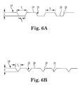
- FIG. 6A is a cross-sectional view of an embodiment of a lapping plate in accordance with embodiments of the present disclosure
- FIG. 6B is a cross-sectional view of another embodiment of a lapping plate in accordance with embodiments of the present disclosure.
- FIG. 7 is a perspective view of a process for forming a lapping plate in accordance with embodiments of the present disclosure.
- FIG. 8 is a perspective view, with an enlarged inset, of a patterning tool used with embodiments of the present disclosure.
- FIG. 9 is a perspective view, with an enlarged inset, of another patterning tool used with embodiments of the present disclosure.
- the present embodiments relate most generally to the manufacture of abrading tools.
- abrading tool in high precision lapping of sliders and the supported magnetic transducing heads used in data storage devices.
- the present disclosure provides a method of abrading (lapping) the slider with a lapping plate or platen having a patterned working surface.
- Lapping processes utilize either oscillatory or rotary motion of a slider bar across a rotating lapping plate to provide a random motion of the slider bar over the lapping plate and randomize plate imperfections across the head surface in the course of lapping.
- Some lapping plates have an abrasiveless horizontal working surface and are used in conjunction with a slurry of abrasive particles (e.g., diamonds), whereas other lapping plates have abrasive particles (e.g., diamonds) embedded in the horizontal working surface.
- the general idea of interrupting the lapping surface for example by forming grooves in the lapping plate, is known in the art.
- the patterned surface reduces hydroplaning of the slider bar on the working surface and liquid and debris (swarf) are centrifugally removed beyond the lapping plate periphery.
- a slider bar lapped on a lapping plate patterned by the methods of this disclosure has decreased microwaviness compared to one lapped on a lapping plate patterned by other methods.
- FIGS. 1 and 2 a generic magnetic recording disc drive is illustrated, having a magnetic recording disc 2 which is rotated by drive motor 4 with hub 6 which is attached to the drive motor 4 .
- a read/write head or transducer 8 is present on the trailing end or surface 9 of a slider 10 .
- Slider 10 is connected an actuator 12 by means of a rigid arm 14 and a suspension element 16 .
- Suspension element 16 provides a bias force which urges slider 10 toward the surface of disc 2 .
- drive motor 4 rotates disc 2 at a constant speed in the direction of arrow 18 and actuator 12 which is typically a linear or rotary motion coil motor drives slider 10 generally radially across the plane of the surface of disc 2 so that read/write head 8 may access different data tracks on disc 2 .
- slider fabrication and finishing must be improved to meet these demands.
- lapping and polishing methodology must be developed which enhance slider features.
- numerous sliders are fabricated from a single wafer having rows of magnetic transducer heads deposited simultaneously on the wafer surface using semiconductor-type process methods.
- Single-row bars are sliced from the wafer, each bar being a row of units that are further processed into sliders each having one or more magnetic transducers or heads on their end faces.
- Each bar is bonded to a fixture or tool for further processing and then further diced i.e., separated into individual sliders.
- the head In order to achieve maximum efficiency of the slider during use, the head, particularly the sensing elements of the head, must have precise dimensions. During manufacturing, it is most critical to grind or lap these elements to very close tolerances of desired thickness in order to achieve the unimpaired functionality required of sliders.
- the present disclosure provides a lapping plate that provides the needed close tolerances while maintaining long plate life.
- the lapping plate is formed using a toothed patterning tool, which plastically deforms the surface of a lapping plate to form a pattern on the working surface.
- FIGS. 3A and 3B diagrammatically depict a lapping plate (also often referred to as a platen) used for machining a slider bar, the plate having been made in accordance with the present disclosure.
- FIG. 3A illustrates a first embodiment as lapping plate 20 A
- FIG. 3B illustrates a second embodiment as lapping plate 20 B.
- Lapping plates 20 A and 20 B have the same overall general features, and discussion relating to one embodiment also applies to the other embodiment, unless specifically indicated otherwise.
- Lapping plate 20 A, 20 B has a body 22 with a working or lapping surface 24 in or on which abrasive particles 30 are present.
- Body 22 has a plurality of indents or cavities 25 therein, with a plurality of land areas 28 between indents 25 .
- Indents 25 were formed by a toothed patterning tool, the tool and method being described below.
- Lapping plate 20 A of FIG. 3A has abrasive particles 30 present on land areas 28
- lapping place 20 B of FIG. 3B has abrasive particles 30 present in indents 25 .
- abrasive particles 30 may be present on land areas 28 .
- Abrasive particles 30 may be electroplated onto land areas 28 , adhesively applied, or may be physically pressed into land areas 28 and mechanically held.
- One method for physically pressing abrasive particles 30 into land areas 28 is by applying an abrasive slurry to a working surface 24 that is composed of a soft metal (e.g., a tin alloy). With the application of pressure, abrasive particles 30 are embedded into the soft metal. Alternately, abrasive particles 30 may be present in indents 25 , as illustrated in FIG. 3B . In FIG.
- abrasive particles 30 are held in indents 25 via an adhesive (e.g., epoxy) 32 . Additional details regarding using an adhesive in the indents to hold abrasive particles can be found in U.S. Patent Publication No. 2012/0009856, the entire disclosure of which is incorporated herein by reference.
- an adhesive e.g., epoxy
- lapping plate 20 A, 20 B is rotated relative to a slider bar 100 containing a plurality of sliders 100 A, 100 B, etc. held in a pressing engagement against working surface 24 .
- the abrading action due to abrasive particles 30 at working surface 24 removes material from slider bar 100 .
- Having the regions free of abrasive particles i.e., indents 25 in FIG. 3A , and land areas 28 in FIG. 3B ) reduces hydroplaning of slider bar 100 on lapping plate 20 A, 20 B and decreases microwaviness on slider bar 100 .
- FIGS. 4 and 5 show the working surface of a lapping plate having a plurality of discrete, individual indents or cavities in the working surface.
- FIG. 4 shows a partial section of a circular lapping plate having an annular working surface and
- FIG. 5 is an enlarged view of a portion of FIG. 4 .
- the working surface shown has a plurality of indents 25 arranged in essentially parallel rows, identified as rows R 1 , R 2 , R 3 and R 4 in FIG. 5 .
- Present between indents 25 are land areas 28 .
- land area 28 is a continuous surface interrupted by indents 25 .
- land area 28 may be composed of multiple unconnected areas.
- each row R 1 , R 2 , R 3 , R 4 extends in a longitudinal direction (top to bottom of the figure).
- the lateral or radial direction extends across rows R 1 , R 2 , R 3 , R 4 (left to right of the figure).
- rows R 1 , R 2 , R 3 and R 4 are concentric circles of indents 25 around a center point of the circular lapping plate and thus land areas 28 are also concentric circles around the center point.
- rows R 1 , R 2 , R 3 and R 4 are one continuous row of indents 25 spiraling out from or into the center point of the circular lapping plate, and thus land areas 28 are also spiraling out from or into the center point.
- indents 25 may be shaped and/or oriented so that the leading edge of indent 25 is not radially aligned.
- FIGS. 6A and 6B illustrate two embodiments of indents 25 .
- indents 25 in working surface 24 are separated by land area 28 having a length L.
- Indent 25 has a side wall 26 extending from working surface 24 to a bottom surface 29 .
- Indent 25 has a maximum width or length dimension l 1 , measured at working surface 24 , and a lesser width of length dimension l 2 , measured at bottom surface 29 .
- sidewall 26 is a sloped, angle or slanted sidewall.
- indent 25 terminates at a point, thus bottom surface 29 has a length dimension l 2 of zero (0).
- Indent 25 has a depth d, measured from working surface 24 to bottom surface 29 .
- indent 25 may be any suitable shape, but generally has a sloped sidewall 26 (i.e., the dimension l 1 , measured at working surface 24 is greater than the dimension l 2 at bottom surface 29 ).
- indents 25 may be circular, oval or elliptical, rectangular (including square), triangular, diamond, or any other polygonal shape.
- indents may be pyramidal (as in FIG. 6B ) or truncated or frusto- (as in FIG. 6A ).
- Truncated or frusto-indents may be formed by a patterning tool having teeth with that truncated or frusto-shape, or the truncated or frusto-indents may be formed by a patterning tool having pointed teeth, the tool not being fully pressed into the lapping plate during the patterning process.
- FIGS. 6A and 6B represent the view from either direction of the indent row, either longitudinally with the row or lateral to multiple rows (e.g., taken in a radial direction). If a longitudinal view of the row, that shown in the figures is the cross section of a portion of one row (the patterning tool having been moved across the page to make each of the shown indents sequentially); if a lateral or radial view of multiple rows, that shown is the cross section of adjacent rows (each indent being in a different row). Indents 25 may have the same dimensions l 1 , l 2 in the longitudinal direction and the lateral direction, or may be different.
- a square indent 25 would have l 1 and l 2 the same in the longitudinal direction and the lateral direction.
- a rectangular indent 25 would have l 1 and l 2 in the longitudinal direction different than l 1 and l 2 in the lateral direction.
- Indents 25 may be equally spaced (i.e., having the same length L therebetween) or may have varying length L therebetween, with length L viewed in either the longitudinal direction of the row or lateral or radial direction.
- the shape and size of indents 25 will differ depending on the lapping process step for which the patterned lapping plate is used.
- the process includes three sequential steps: a rough lapping step, a fine lapping step, and a kiss lapping step.
- the abrasive particles e.g., diamonds
- the abrasive particles are usually about 1 to about 5 micrometers in size
- the abrasive particles are usually about 0.1 to about 1 micrometer in size
- the abrasive particles are usually less than 0.1 micrometer.
- the depth d from working surface 24 to bottom 29 is preferably no more than 1000 micrometers, in some embodiments no more than about 500 micrometers.
- the depth d from working surface 24 to bottom 29 is preferably no more than 100 micrometers, in some embodiments no more than about 10 micrometers, and in some embodiments about 5 to 10 micrometers (e.g., about 6 micrometers);
- the depth d from working surface 24 to bottom 29 is preferably no more than 10 micrometers, in some embodiments no more than about 1 micrometer;
- the depth d from working surface 24 to bottom 29 is preferably no more than 1 micrometer, in some embodiments about 0.5 micrometer of less.
- the largest dimension of indent 25 which for a tapered structure will be length l 1 , is preferably no more than 100 micrometers, in some embodiments no more than about 500 micrometers.
- a dimension l 1 within the range of about 100 micrometers to about 200 micrometers is suitable.
- indent 25 has a greatest dimension l 1 at working surface 24 of about 790 micrometers, a dimension l 2 at distal end 29 of about 430 micrometers, and a depth d of about 800 micrometers.
- indent 25 has a greatest dimension l 1 at working surface 24 of about 700 micrometers, a pointed distal end 29 , and a depth d of about 800 micrometers.
- the lapping plate of the present disclosure is formed by forming a pattern into the lapping plate with a toothed patterning tool.
- the patterning process of this disclosure may be referred to as roll knurling or form knurling; such a process is done by pressing a wheel or tool against a workpiece with sufficient force to cold form or plastically deform the outer surface of the workpiece.
- the patterning tool has the inverse of the pattern that is to be imparted to the workpiece.
- FIG. 7 illustrates a set-up suitable for providing the patterned lapping plate.
- a support 50 rotatably retains a toothed patterning tool 52 .
- As support 50 moves radially across rotating lapping plate 20 sufficient pressure is provided by support 50 so that tool 52 contacts plate 20 and imparts the inverse of its pattern in a plurality of rows Rx, Ry, etc. onto plate 20 .
- If support 50 move continuously and uninterrupted radially across rotating lapping plate 20 the result is one continuous spiral of indents in lapping plate 20 .
- support 50 may be fixed in position for one rotation of lapping plate 20 , after which support 50 is lifted and moved radially (in or out) to another fixed position, and so on; the result is concentric rows of indents in lapping plate 20 .
- the rows of indents can have equal or unequal spacing (in the radial direction) therebetween.
- the radial distance between row R 1 and R 2 is less than the radial distance between row R 2 and R 3 .
- the radial distance between row R 3 and R 4 is less than the radial distance between row R 2 and R 3 .
- FIG. 6B if showing a lateral view of multiple rows, also shows varying radial distance between rows, whereas FIG. 6A shows an equal distance between rows.
- FIG. 8 illustrates a first embodiment as patterning tool 52 A
- FIG. 9 illustrates a second embodiment as patterning tool 52 B.
- Patterning tools 52 A, 52 B have the same overall general features, and discussion relating to one embodiment also applies to the other embodiment, unless specifically indicated otherwise.
- Each tool 52 A, 52 B has a plurality of teeth 54 extending around an outer circumference 55 of the cylindrical tool 52 A, 52 B.
- Each tooth 54 has at least one sidewall 56 that extends from outer circumference 55 to a distal end 59 .
- the cross-sectional area (taken essentially parallel to circumference 55 ) of tooth 54 tapers from outer circumference 55 to distal end 59 .
- adjacent sidewalls 56 i.e., those opposite each other of adjacent teeth 54 , in the circumference direction
- outer sidewalls 56 i.e., those orthogonal to the sidewalls 56 in the circumferential direction
- all four sidewalls 56 are angled or slanted in toward distal end 59 . All sidewalls 56 may have the same angle from circumference 55 to distal end 59 or may have different angles.
- distal end 59 is a flat polygon—a rectangle for tool 52 A and a square for tool 52 B, whereas a tool used to form pointed indents, such as indents 25 of FIG. 6B , would have a point of line defining distal end 59 .
- patterning tool 52 A, 52 B or other is mounted on support 50 , as illustrated in FIG. 7 .
- support 50 moves radially across rotating lapping plate 20
- sufficient pressure is provided by support 50 so that the rotating patterning tool deforms the surface of lapping plate 20 , imparting the inverse of its pattern in a plurality of rows Rx, Ry, etc. onto plate 20 .
- sufficient pressure may be provided to the patterning tool so that the entire tooth 54 embeds in the plate surface deforming the surface and forming the indent, however, in most embodiments only a portion of tooth 54 will embed in the plate surface.
Abstract
A method of forming a patterned lapping plate by providing a working tool having a pattern comprising a plurality of raised teeth, each of the raised teeth having a base, at least one side wall, and a terminal end, and patterning the lapping plate with the tool to provide a working surface having an inverse pattern of the tool surface in the working surface of the lapping plate, the patterning process plastically deforming the working surface of the lapping plate.
Description
Hard disc drive systems (HDDs) typically include one or more data storage discs. A transducing head carried by a slider is used to read from and write to a data track on a disc. The slider is carried by an arm assembly that includes an actuator arm and a suspension assembly, which can include a separate gimbal structure or can integrally form a gimbal.
The density of data stored on a disc continues to increase, requiring more precise positioning of the transducing head. Conventionally, in many systems, head positioning is accomplished by operating the actuator arm with a large scale actuation motor, such as a voice coil motor, to position a head on a flexure at the end of the actuator arm. A high resolution head positioning mechanism, or microactuator, is advantageous to accommodate the high data density. The microactuator is often a piezoelectric microactuator.
Electrical connections between various elements in the HDD system should be strong, resist breakage, and have good electrical conductivity. Improved electrical connections are always desirable. The present disclosure provides sliders and transducing heads with improved electrical connections.
One particular embodiment of this disclosure is a method of patterning a lapping plate. The method includes providing a working tool having a pattern comprising a plurality of raised teeth, each of the raised teeth having a base, at least one side wall, and a terminal end, and patterning the lapping plate with the tool to provide a working surface having an inverse pattern of the tool surface in the working surface of the lapping plate, the patterning process plastically deforming the working surface of the lapping plate.
Another particular embodiment of this disclosure is a patterned lapping plate. The lapping plate comprises a working surface comprising a plurality of discrete indents separated by a continuous land area. Each indent has a depth from the working surface to a terminal end of the indents of no more than 100 micrometers, slanted side walls extending from the working surface to a terminal end of the indent, and a largest dimension of the indent at the working surface of no greater than 1000 micrometers.
Another particular embodiment of this disclosure is a patterned lapping plate. The lapping plate comprises a working surface comprising a groove spiraling about a central axis of the lapping plate forming a plurality of turns, and land area positioned between adjacent turns of the spiraling groove. The groove has slanted side walls extending from the working surface to a terminal end of the groove, a depth from the working surface to the terminal end of no more than 100 micrometers, and a varying width along the length of the groove.
These and various other features and advantages will be apparent from a reading of the following detailed description.
The disclosure may be more completely understood in consideration of the following detailed description of various embodiments of the disclosure in connection with the accompanying drawing, in which:
The present embodiments relate most generally to the manufacture of abrading tools. For purposes of this description, although not so limited, reference is made to the use of an abrading tool in high precision lapping of sliders and the supported magnetic transducing heads used in data storage devices. The sliders and particularly the heads, operably used to store and retrieve data on rotatable magnetic recording discs, require extremely precise manufacturing tolerances. The present disclosure provides a method of abrading (lapping) the slider with a lapping plate or platen having a patterned working surface.
Lapping processes utilize either oscillatory or rotary motion of a slider bar across a rotating lapping plate to provide a random motion of the slider bar over the lapping plate and randomize plate imperfections across the head surface in the course of lapping. Some lapping plates have an abrasiveless horizontal working surface and are used in conjunction with a slurry of abrasive particles (e.g., diamonds), whereas other lapping plates have abrasive particles (e.g., diamonds) embedded in the horizontal working surface. The general idea of interrupting the lapping surface, for example by forming grooves in the lapping plate, is known in the art. The patterned surface reduces hydroplaning of the slider bar on the working surface and liquid and debris (swarf) are centrifugally removed beyond the lapping plate periphery.
Problems exist with grooved plates, for example, excessive width and/or depth of grooves allow abrasive particles to loose their effectiveness due to lack of contact with the slider bar. Grooves that are too wide provide surface discontinuity too severe for small work pieces. Even if the grooves can be sized properly, forming the grooves can be costly and time consuming. Additionally, over time the lapping plate wears and dulls, requiring refurbishment of the working surface, which again can be time consuming and expensive, and which greatly shortens the total useful life of the lapping plate. By forming a pattern in the lapping plate, as per the present disclosure, improvements over conventional grooved plates are observed. Because the patterning process plastically deforms the lapping plate surface rather than removing material, the useful life of the lapping plate is extended by providing for repeated refurbishment of the patterned surface. Additionally, a slider bar lapped on a lapping plate patterned by the methods of this disclosure has decreased microwaviness compared to one lapped on a lapping plate patterned by other methods.
In the following description, reference is made to the accompanying drawing that forms a part hereof and in which are shown by way of illustration at least one specific embodiment. The following description provides additional specific embodiments. It is to be understood that other embodiments are contemplated and may be made without departing from the scope or spirit of the present disclosure. The following detailed description, therefore, is not to be taken in a limiting sense. While the present disclosure is not so limited, an appreciation of various aspects of the disclosure will be gained through a discussion of the examples provided below.
Unless otherwise indicated, all numbers expressing feature sizes, amounts, and physical properties are to be understood as being modified by the term “about.” Accordingly, unless indicated to the contrary, the numerical parameters set forth are approximations that can vary depending upon the desired properties sought to be obtained by those skilled in the art utilizing the teachings disclosed herein.
As used herein, the singular forms “a”, “an”, and “the” encompass embodiments having plural referents, unless the content clearly dictates otherwise. As used in this specification and the appended claims, the term “or” is generally employed in its sense including “and/or” unless the content clearly dictates otherwise.
Referring to FIGS. 1 and 2 , a generic magnetic recording disc drive is illustrated, having a magnetic recording disc 2 which is rotated by drive motor 4 with hub 6 which is attached to the drive motor 4. A read/write head or transducer 8 is present on the trailing end or surface 9 of a slider 10. Slider 10 is connected an actuator 12 by means of a rigid arm 14 and a suspension element 16. Suspension element 16 provides a bias force which urges slider 10 toward the surface of disc 2. During operation of the disc drive, drive motor 4 rotates disc 2 at a constant speed in the direction of arrow 18 and actuator 12 which is typically a linear or rotary motion coil motor drives slider 10 generally radially across the plane of the surface of disc 2 so that read/write head 8 may access different data tracks on disc 2.
In order to meet the increasing demands for more and more data storage capacity on disc 2, slider fabrication and finishing must be improved to meet these demands. To meet these demands, lapping and polishing methodology must be developed which enhance slider features. Typically, numerous sliders are fabricated from a single wafer having rows of magnetic transducer heads deposited simultaneously on the wafer surface using semiconductor-type process methods. Single-row bars are sliced from the wafer, each bar being a row of units that are further processed into sliders each having one or more magnetic transducers or heads on their end faces. Each bar is bonded to a fixture or tool for further processing and then further diced i.e., separated into individual sliders.
In order to achieve maximum efficiency of the slider during use, the head, particularly the sensing elements of the head, must have precise dimensions. During manufacturing, it is most critical to grind or lap these elements to very close tolerances of desired thickness in order to achieve the unimpaired functionality required of sliders. The present disclosure provides a lapping plate that provides the needed close tolerances while maintaining long plate life. The lapping plate is formed using a toothed patterning tool, which plastically deforms the surface of a lapping plate to form a pattern on the working surface.
Referring to FIG. 3A , abrasive particles 30 may be present on land areas 28. Abrasive particles 30 may be electroplated onto land areas 28, adhesively applied, or may be physically pressed into land areas 28 and mechanically held. One method for physically pressing abrasive particles 30 into land areas 28 is by applying an abrasive slurry to a working surface 24 that is composed of a soft metal (e.g., a tin alloy). With the application of pressure, abrasive particles 30 are embedded into the soft metal. Alternately, abrasive particles 30 may be present in indents 25, as illustrated in FIG. 3B . In FIG. 3B , abrasive particles 30 are held in indents 25 via an adhesive (e.g., epoxy) 32. Additional details regarding using an adhesive in the indents to hold abrasive particles can be found in U.S. Patent Publication No. 2012/0009856, the entire disclosure of which is incorporated herein by reference.
In use, lapping plate 20A, 20B is rotated relative to a slider bar 100 containing a plurality of sliders 100A, 100B, etc. held in a pressing engagement against working surface 24. The abrading action due to abrasive particles 30 at working surface 24 removes material from slider bar 100. Having the regions free of abrasive particles (i.e., indents 25 in FIG. 3A , and land areas 28 in FIG. 3B ) reduces hydroplaning of slider bar 100 on lapping plate 20A, 20B and decreases microwaviness on slider bar 100.
For orientation understanding, as viewed in FIG. 5 , each row R1, R2, R3, R4 extends in a longitudinal direction (top to bottom of the figure). The lateral or radial direction extends across rows R1, R2, R3, R4 (left to right of the figure).
In some embodiments, rows R1, R2, R3 and R4 are concentric circles of indents 25 around a center point of the circular lapping plate and thus land areas 28 are also concentric circles around the center point. In other embodiments, rows R1, R2, R3 and R4 are one continuous row of indents 25 spiraling out from or into the center point of the circular lapping plate, and thus land areas 28 are also spiraling out from or into the center point. In some embodiments, indents 25 may be shaped and/or oriented so that the leading edge of indent 25 is not radially aligned.
The shape of indent 25 may be any suitable shape, but generally has a sloped sidewall 26 (i.e., the dimension l1, measured at working surface 24 is greater than the dimension l2 at bottom surface 29). When viewed from the top, as in FIG. 5 , indents 25 may be circular, oval or elliptical, rectangular (including square), triangular, diamond, or any other polygonal shape. When viewed from the side, as in FIGS. 6A and 6B , indents may be pyramidal (as in FIG. 6B ) or truncated or frusto- (as in FIG. 6A ). Particularly suitable shapes for indents 25 include truncated pyramidal (e.g., a truncated three-sided, four-sided pyramid), elongated pyramidal and frusto-conical (i.e., a truncated cone). Truncated or frusto-indents may be formed by a patterning tool having teeth with that truncated or frusto-shape, or the truncated or frusto-indents may be formed by a patterning tool having pointed teeth, the tool not being fully pressed into the lapping plate during the patterning process.
The shape and size of indents 25 will differ depending on the lapping process step for which the patterned lapping plate is used. For most lapping processes, the process includes three sequential steps: a rough lapping step, a fine lapping step, and a kiss lapping step. For a rough lapping step, the abrasive particles (e.g., diamonds) are usually about 1 to about 5 micrometers in size; for a fine lapping step, the abrasive particles are usually about 0.1 to about 1 micrometer in size; for a kiss lapping step, the abrasive particles are usually less than 0.1 micrometer.
In general, for any lapping step, the depth d from working surface 24 to bottom 29 is preferably no more than 1000 micrometers, in some embodiments no more than about 500 micrometers. For a rough lapping step, the depth d from working surface 24 to bottom 29 is preferably no more than 100 micrometers, in some embodiments no more than about 10 micrometers, and in some embodiments about 5 to 10 micrometers (e.g., about 6 micrometers); for a fine lapping step, the depth d from working surface 24 to bottom 29 is preferably no more than 10 micrometers, in some embodiments no more than about 1 micrometer; for a kiss lapping step, the depth d from working surface 24 to bottom 29 is preferably no more than 1 micrometer, in some embodiments about 0.5 micrometer of less. In general, for any lapping step, the largest dimension of indent 25, which for a tapered structure will be length l1, is preferably no more than 100 micrometers, in some embodiments no more than about 500 micrometers. For any of the lapping steps, a dimension l1 within the range of about 100 micrometers to about 200 micrometers is suitable.
As one particular example, for a tool having a pattern such as that of FIG. 6A , indent 25 has a greatest dimension l1 at working surface 24 of about 790 micrometers, a dimension l2 at distal end 29 of about 430 micrometers, and a depth d of about 800 micrometers. As another particular example, for a tool having a pattern such as that of FIG. 6B , indent 25 has a greatest dimension l1 at working surface 24 of about 700 micrometers, a pointed distal end 29, and a depth d of about 800 micrometers.
As discussed above, the lapping plate of the present disclosure is formed by forming a pattern into the lapping plate with a toothed patterning tool. In some embodiments, the patterning process of this disclosure may be referred to as roll knurling or form knurling; such a process is done by pressing a wheel or tool against a workpiece with sufficient force to cold form or plastically deform the outer surface of the workpiece. The patterning tool has the inverse of the pattern that is to be imparted to the workpiece.
The rows of indents can have equal or unequal spacing (in the radial direction) therebetween. For example, referring to FIG. 5 , the radial distance between row R1 and R2 is less than the radial distance between row R2 and R3. Likewise, the radial distance between row R3 and R4 is less than the radial distance between row R2 and R3. FIG. 6B , if showing a lateral view of multiple rows, also shows varying radial distance between rows, whereas FIG. 6A shows an equal distance between rows.
Two examples of suitable patterning tools are illustrated in FIG. 8 and in FIG. 9 . FIG. 8 illustrates a first embodiment as patterning tool 52A and FIG. 9 illustrates a second embodiment as patterning tool 52B. Patterning tools 52A, 52B have the same overall general features, and discussion relating to one embodiment also applies to the other embodiment, unless specifically indicated otherwise. Each tool 52A, 52B has a plurality of teeth 54 extending around an outer circumference 55 of the cylindrical tool 52A, 52B. Each tooth 54 has at least one sidewall 56 that extends from outer circumference 55 to a distal end 59. The cross-sectional area (taken essentially parallel to circumference 55) of tooth 54 tapers from outer circumference 55 to distal end 59. For tool 52A of FIG. 8 , adjacent sidewalls 56 (i.e., those opposite each other of adjacent teeth 54, in the circumference direction) slant away from each other, whereas the outer sidewalls 56 (i.e., those orthogonal to the sidewalls 56 in the circumferential direction) do not slant but extend orthogonally out from outer circumference 55. Conversely, for tool 52B of FIG. 9 , all four sidewalls 56 are angled or slanted in toward distal end 59. All sidewalls 56 may have the same angle from circumference 55 to distal end 59 or may have different angles. In both patterning tool 52A and 52B, distal end 59 is a flat polygon—a rectangle for tool 52A and a square for tool 52B, whereas a tool used to form pointed indents, such as indents 25 of FIG. 6B , would have a point of line defining distal end 59.
To form a patterned lapping plate according to this disclosure, patterning tool 52A, 52B or other is mounted on support 50, as illustrated in FIG. 7 . As support 50 moves radially across rotating lapping plate 20, sufficient pressure is provided by support 50 so that the rotating patterning tool deforms the surface of lapping plate 20, imparting the inverse of its pattern in a plurality of rows Rx, Ry, etc. onto plate 20. In some embodiments sufficient pressure may be provided to the patterning tool so that the entire tooth 54 embeds in the plate surface deforming the surface and forming the indent, however, in most embodiments only a portion of tooth 54 will embed in the plate surface.
It is understood that numerous variations of the patterning tools and methods of using the patterning tools could be made to form patterned lapping plates while maintaining the overall inventive design and remaining within the scope of the disclosure. Numerous alternate design or element features have been mentioned above.
Thus, embodiments of the METHOD OF PATTERNING A LAPPING PLATE, AND PATTERNED LAPPING PLATES are disclosed. The implementations described above and other implementations are within the scope of the following claims. One skilled in the art will appreciate that the present invention can be practiced with embodiments other than those disclosed. The disclosed embodiments are presented for purposes of illustration and not limitation, and the present invention is limited only by the claims that follow.
Claims (16)
1. A metal lapping plate comprising a working surface comprising a plurality of discrete square indents separated by a continuous land area, with an abrasive coating affixed to the lapping plate, the indents comprising:
a depth from the working surface to a terminal end of the indents of no more than 100 micrometers;
all side walls slanting towards each other and extending from the working surface to a terminal end of the indent;
with no side wall of the square indents having a dimension at the working surface greater than 1000 micrometers.
2. The lapping plate of claim 1 wherein the terminal end of the indent is defined by a point.
3. The lapping plate of claim 1 wherein the terminal end of the indent is defined by a flat surface.
4. The lapping plate of claim 1 wherein the depth is no more than about 10 micrometers.
5. The lapping plate of claim 1 wherein the depth is no more than about 1 micrometer.
6. A metal lapping plate comprising a working surface having affixed thereto an abrasive coating, the working surface comprising:
a groove having a length spiraling about a central axis of the lapping plate forming a plurality of turns, the groove having:
slanted side walls tapering from a surface width at the working surface to a terminal width at a terminal end of the groove, the terminal width less than the surface width;
a depth from the working surface to the terminal end of no more than 100 micrometers; and
the surface width varying along the length of the groove; and
a land area positioned between adjacent turns of the spiraling groove.
7. The lapping plate of claim 6 wherein the terminal end of the groove is defined by a point.
8. The lapping plate of claim 6 wherein the terminal end of the groove is defined by a flat end.
9. The lapping plate of claim 6 wherein the depth of the groove is no more than about 10 micrometers.
10. The lapping plate of claim 6 wherein the surface width of the groove varies along the length of the groove within the range of about 500 to 1000 micrometers.
11. A lapping plate comprising:
a working surface comprising a plurality of elongate grooves concentrically spiraling around a central axis of the working surface, and a land area, the land area having a plurality of abrasive particles secured thereto, the elongate grooves comprising:
a depth from the working surface to a terminal end of the elongate groove of no more than 100 micrometers; and
a width at the working surface greater than a width at the terminal end of the elongate groove, with the width at the working surface not constant along a length of the elongate groove.
12. The lapping plate of claim 11 , wherein the plurality of elongate grooves comprises a plurality of elongate grooves having no dimension at the working surface greater than 1000 micrometers.
13. The lapping plate of claim 12 , wherein the terminal end is defined by a rectangle and the elongate groove comprises four slanted side walls tapering to the terminal end.
14. The lapping plate of claim 11 wherein the terminal end of the elongate groove is defined by a flat surface.
15. The lapping plate of claim 11 wherein the depth is no more than about 10 micrometers.
16. The lapping plate of claim 15 wherein the depth is no more than about 1 micrometer.
Priority Applications (5)
| Application Number | Priority Date | Filing Date | Title |
|---|---|---|---|
| US13/716,456 US9522454B2 (en) | 2012-12-17 | 2012-12-17 | Method of patterning a lapping plate, and patterned lapping plates |
| CN201310757298.6A CN103862362A (en) | 2012-12-17 | 2013-12-16 | Method of patterning a lapping plate, and patterned lapping plates |
| JP2013259247A JP6130292B2 (en) | 2012-12-17 | 2013-12-16 | Method for applying pattern to wrapping plate and wrapping plate |
| EP13197788.6A EP2743031A1 (en) | 2012-12-17 | 2013-12-17 | Method of patterning a lapping plate, and patterned lapping plates |
| KR1020130157335A KR101620080B1 (en) | 2012-12-17 | 2013-12-17 | Method of patterning a lapping plate, and patterned lapping plates |
Applications Claiming Priority (1)
| Application Number | Priority Date | Filing Date | Title |
|---|---|---|---|
| US13/716,456 US9522454B2 (en) | 2012-12-17 | 2012-12-17 | Method of patterning a lapping plate, and patterned lapping plates |
Publications (2)
| Publication Number | Publication Date |
|---|---|
| US20140170944A1 US20140170944A1 (en) | 2014-06-19 |
| US9522454B2 true US9522454B2 (en) | 2016-12-20 |
Family
ID=49886645
Family Applications (1)
| Application Number | Title | Priority Date | Filing Date |
|---|---|---|---|
| US13/716,456 Active 2034-04-07 US9522454B2 (en) | 2012-12-17 | 2012-12-17 | Method of patterning a lapping plate, and patterned lapping plates |
Country Status (5)
| Country | Link |
|---|---|
| US (1) | US9522454B2 (en) |
| EP (1) | EP2743031A1 (en) |
| JP (1) | JP6130292B2 (en) |
| KR (1) | KR101620080B1 (en) |
| CN (1) | CN103862362A (en) |
Families Citing this family (7)
| Publication number | Priority date | Publication date | Assignee | Title |
|---|---|---|---|---|
| KR101455919B1 (en) * | 2013-01-18 | 2014-11-03 | 주식회사 엘지실트론 | Structure of Lapping Plate in Double Side Lapping Apparatus For Silicon Wafer |
| US10144901B2 (en) | 2016-02-15 | 2018-12-04 | Seagate Technology Llc | Lubricant composition for lapping ceramic material, and related methods |
| US10105813B2 (en) | 2016-04-20 | 2018-10-23 | Seagate Technology Llc | Lapping plate and method of making |
| US10010996B2 (en) | 2016-04-20 | 2018-07-03 | Seagate Technology Llc | Lapping plate and method of making |
| TWI595968B (en) * | 2016-08-11 | 2017-08-21 | 宋建宏 | Polishing pad and method for manufacturing the same |
| WO2018142623A1 (en) * | 2017-02-06 | 2018-08-09 | 株式会社大輝 | Polishing pad recess forming method and polishing pad |
| IL309873A (en) * | 2021-08-04 | 2024-03-01 | Kuraray Co | Polishing pad |
Citations (44)
| Publication number | Priority date | Publication date | Assignee | Title |
|---|---|---|---|---|
| US3921342A (en) | 1973-12-17 | 1975-11-25 | Spitfire Tool & Machine Co Inc | Lap plate |
| US4037367A (en) | 1975-12-22 | 1977-07-26 | Kruse James A | Grinding tool |
| US4369604A (en) * | 1981-02-27 | 1983-01-25 | Rca Corporation | Method for mechanically preparing stylus lapping discs |
| US4821461A (en) | 1987-11-23 | 1989-04-18 | Magnetic Peripherals Inc. | Textured lapping plate and process for its manufacture |
| US4866886A (en) | 1987-11-23 | 1989-09-19 | Magnetic Peripherals Inc. | Textured lapping plate and process for its manufacture |
| JPH04102769A (en) | 1990-08-22 | 1992-04-03 | Uchiyama Mfg Corp | Oil seal |
| US5899799A (en) * | 1996-01-19 | 1999-05-04 | Micron Display Technology, Inc. | Method and system to increase delivery of slurry to the surface of large substrates during polishing operations |
| KR19990063984A (en) | 1995-10-05 | 1999-07-26 | 스프레이그 로버트 월터 | Methods and apparatus for knurling workpieces, methods for molding products into such workpieces, and such molded products |
| US5946991A (en) | 1997-09-03 | 1999-09-07 | 3M Innovative Properties Company | Method for knurling a workpiece |
| US5975987A (en) | 1995-10-05 | 1999-11-02 | 3M Innovative Properties Company | Method and apparatus for knurling a workpiece, method of molding an article with such workpiece, and such molded article |
| US6050879A (en) | 1998-06-30 | 2000-04-18 | Ibm | Process for lapping air bearing surfaces |
| US6093651A (en) * | 1997-12-23 | 2000-07-25 | Intel Corporation | Polish pad with non-uniform groove depth to improve wafer polish rate uniformity |
| US20010031612A1 (en) | 2000-01-06 | 2001-10-18 | Scott Diane B. | Retention of a polishing pad on a platen |
| US20020068516A1 (en) * | 1999-12-13 | 2002-06-06 | Applied Materials, Inc | Apparatus and method for controlled delivery of slurry to a region of a polishing device |
| US6443810B1 (en) * | 2000-04-11 | 2002-09-03 | Taiwan Semiconductor Manufacturing Co., Ltd. | Polishing platen equipped with guard ring for chemical mechanical polishing |
| JP2002292573A (en) | 2001-03-30 | 2002-10-08 | Dainippon Printing Co Ltd | Abrasive film and its manufacturing method |
| US6539277B1 (en) | 2000-07-18 | 2003-03-25 | Agilent Technologies, Inc. | Lapping surface patterning system |
| US20030060144A1 (en) | 2001-08-24 | 2003-03-27 | Taylor Theodore M. | Apparatus and method for conditioning a contact surface of a processing pad used in processing microelectronic workpieces |
| US6540590B1 (en) * | 2000-08-31 | 2003-04-01 | Multi-Planar Technologies, Inc. | Chemical mechanical polishing apparatus and method having a rotating retaining ring |
| US20030119425A1 (en) * | 2001-12-19 | 2003-06-26 | Toho Engineering Kabushiki Kaisha | Turning tool for grooving polishing pad, apparatus and method of producing polishing pad using the tool, and polishing pad produced by using the tool |
| US20030132207A1 (en) * | 2001-08-02 | 2003-07-17 | Inha Park | Method for fabricating chemical mechanical polshing pad using laser |
| US20030150169A1 (en) | 2001-12-28 | 2003-08-14 | 3M Innovative Properties Company | Method of making an abrasive product |
| US6802761B1 (en) | 2003-03-20 | 2004-10-12 | Hitachi Global Storage Technologies Netherlands B.V. | Pattern-electroplated lapping plates for reduced loads during single slider lapping and process for their fabrication |
| JP2005118988A (en) | 2003-10-10 | 2005-05-12 | Sae Magnetics (Hk) Ltd | Method and device for imparting texture to gmr lapping plate by using photochemical process |
| US20050276967A1 (en) * | 2002-05-23 | 2005-12-15 | Cabot Microelectronics Corporation | Surface textured microporous polishing pads |
| US20060154577A1 (en) * | 1999-07-08 | 2006-07-13 | Toho Engineering Kabushiki Kaisha | Method of producing polishing pad |
| US20060229002A1 (en) * | 2005-04-12 | 2006-10-12 | Muldowney Gregory P | Radial-biased polishing pad |
| US20070015442A1 (en) * | 2005-07-15 | 2007-01-18 | Samsung Electronics Co., Ltd. | Method and apparatus for measuring abrasion amount and pad friction force of polishing pad using thickness change of slurry film |
| US20070032182A1 (en) * | 2002-04-03 | 2007-02-08 | Toho Engineering Kabushiki Kaisha | Polishing pad and method of fabricating semiconductor substrate using the pad |
| US20070066195A1 (en) * | 2005-09-19 | 2007-03-22 | Duong Chau H | Water-based polishing pads having improved adhesion properties and methods of manufacture |
| US20070082587A1 (en) * | 2004-05-20 | 2007-04-12 | Jsr Corporation | Method of manufacturing chemical mechanical polishing pad |
| US7234224B1 (en) * | 2006-11-03 | 2007-06-26 | Rohm And Haas Electronic Materials Cmp Holdings, Inc. | Curved grooving of polishing pads |
| US20070149096A1 (en) * | 2005-12-28 | 2007-06-28 | Jsr Corporation | Chemical mechanical polishing pad and chemical mechanical polishing method |
| US20070232200A1 (en) * | 2006-03-31 | 2007-10-04 | Tmp Co., Ltd. | Grinding sheet and grinding method |
| US20080139089A1 (en) * | 2006-12-01 | 2008-06-12 | Nihon Micro Coating Co., Ltd. | Method of polishing hard crystal substrate and polishing oil slurry therefor |
| US7410410B2 (en) | 2005-10-13 | 2008-08-12 | Sae Magnetics (H.K.) Ltd. | Method and apparatus to produce a GRM lapping plate with fixed diamond using electro-deposition techniques |
| US20090258575A1 (en) * | 2007-08-15 | 2009-10-15 | Richard D Hreha | Chemical Mechanical Polishing Pad and Methods of Making and Using Same |
| US7662021B2 (en) | 2007-04-17 | 2010-02-16 | Hitachi Global Storage Technologies Netherlands B.V. | Lapping plate texture for increased control over actual lapping force |
| JP2010194692A (en) | 2009-02-26 | 2010-09-09 | Epson Toyocom Corp | Surface plate and polishing device |
| US20110195646A1 (en) * | 2008-10-10 | 2011-08-11 | Myung Mook Kim | Polishing pad having a tricot mesh faberic as a base |
| US20110239444A1 (en) * | 2010-03-31 | 2011-10-06 | Hitachi, Ltd. | Method of Manufacturing Lapping Plate, and Method of Manufacturing Magnetic Head Slider using the Lapping Plate |
| US8062098B2 (en) | 2000-11-17 | 2011-11-22 | Duescher Wayne O | High speed flat lapping platen |
| US20120009856A1 (en) | 2010-07-07 | 2012-01-12 | Seagate Technology Llc | Lapping a workpiece |
| JP2013240844A (en) | 2012-05-18 | 2013-12-05 | Tdk Corp | Polishing table, polishing device using the same, and stamping device for manufacturing polishing table |
Family Cites Families (5)
| Publication number | Priority date | Publication date | Assignee | Title |
|---|---|---|---|---|
| DE3724106A1 (en) * | 1987-07-21 | 1989-02-02 | Richard Hahn Diamant Werkzeuge | Process for producing a face-grinding disc and face-grinding disc produced according to this process for machining hard materials |
| JPH04102769U (en) * | 1991-02-15 | 1992-09-04 | シチズン時計株式会社 | Recess formation jig for wrapping surface plate |
| DE60039054D1 (en) * | 1999-03-30 | 2008-07-10 | Nikon Corp | GT POLISHING BODY, POLISHING DEVICE, POLISHING METHOD AND METHOD FOR MANUFACTURING A SEMICONDUCTOR DEVICE (2002/23) |
| US20030194959A1 (en) * | 2002-04-15 | 2003-10-16 | Cabot Microelectronics Corporation | Sintered polishing pad with regions of contrasting density |
| KR101334012B1 (en) * | 2005-07-25 | 2013-12-02 | 호야 가부시키가이샤 | Manufacturing method of substrate for mask blank, and manufacturing method of mask blank and mask |
-
2012
- 2012-12-17 US US13/716,456 patent/US9522454B2/en active Active
-
2013
- 2013-12-16 CN CN201310757298.6A patent/CN103862362A/en active Pending
- 2013-12-16 JP JP2013259247A patent/JP6130292B2/en active Active
- 2013-12-17 EP EP13197788.6A patent/EP2743031A1/en not_active Withdrawn
- 2013-12-17 KR KR1020130157335A patent/KR101620080B1/en active IP Right Grant
Patent Citations (45)
| Publication number | Priority date | Publication date | Assignee | Title |
|---|---|---|---|---|
| US3921342A (en) | 1973-12-17 | 1975-11-25 | Spitfire Tool & Machine Co Inc | Lap plate |
| US4037367A (en) | 1975-12-22 | 1977-07-26 | Kruse James A | Grinding tool |
| US4369604A (en) * | 1981-02-27 | 1983-01-25 | Rca Corporation | Method for mechanically preparing stylus lapping discs |
| US4821461A (en) | 1987-11-23 | 1989-04-18 | Magnetic Peripherals Inc. | Textured lapping plate and process for its manufacture |
| US4866886A (en) | 1987-11-23 | 1989-09-19 | Magnetic Peripherals Inc. | Textured lapping plate and process for its manufacture |
| JPH04102769A (en) | 1990-08-22 | 1992-04-03 | Uchiyama Mfg Corp | Oil seal |
| KR19990063984A (en) | 1995-10-05 | 1999-07-26 | 스프레이그 로버트 월터 | Methods and apparatus for knurling workpieces, methods for molding products into such workpieces, and such molded products |
| US5975987A (en) | 1995-10-05 | 1999-11-02 | 3M Innovative Properties Company | Method and apparatus for knurling a workpiece, method of molding an article with such workpiece, and such molded article |
| US5899799A (en) * | 1996-01-19 | 1999-05-04 | Micron Display Technology, Inc. | Method and system to increase delivery of slurry to the surface of large substrates during polishing operations |
| US5946991A (en) | 1997-09-03 | 1999-09-07 | 3M Innovative Properties Company | Method for knurling a workpiece |
| US6093651A (en) * | 1997-12-23 | 2000-07-25 | Intel Corporation | Polish pad with non-uniform groove depth to improve wafer polish rate uniformity |
| US6050879A (en) | 1998-06-30 | 2000-04-18 | Ibm | Process for lapping air bearing surfaces |
| US20060154577A1 (en) * | 1999-07-08 | 2006-07-13 | Toho Engineering Kabushiki Kaisha | Method of producing polishing pad |
| US20020068516A1 (en) * | 1999-12-13 | 2002-06-06 | Applied Materials, Inc | Apparatus and method for controlled delivery of slurry to a region of a polishing device |
| US20010031612A1 (en) | 2000-01-06 | 2001-10-18 | Scott Diane B. | Retention of a polishing pad on a platen |
| US6443810B1 (en) * | 2000-04-11 | 2002-09-03 | Taiwan Semiconductor Manufacturing Co., Ltd. | Polishing platen equipped with guard ring for chemical mechanical polishing |
| US6539277B1 (en) | 2000-07-18 | 2003-03-25 | Agilent Technologies, Inc. | Lapping surface patterning system |
| US6540590B1 (en) * | 2000-08-31 | 2003-04-01 | Multi-Planar Technologies, Inc. | Chemical mechanical polishing apparatus and method having a rotating retaining ring |
| US8062098B2 (en) | 2000-11-17 | 2011-11-22 | Duescher Wayne O | High speed flat lapping platen |
| JP2002292573A (en) | 2001-03-30 | 2002-10-08 | Dainippon Printing Co Ltd | Abrasive film and its manufacturing method |
| US20030132207A1 (en) * | 2001-08-02 | 2003-07-17 | Inha Park | Method for fabricating chemical mechanical polshing pad using laser |
| US20030060144A1 (en) | 2001-08-24 | 2003-03-27 | Taylor Theodore M. | Apparatus and method for conditioning a contact surface of a processing pad used in processing microelectronic workpieces |
| US20030119425A1 (en) * | 2001-12-19 | 2003-06-26 | Toho Engineering Kabushiki Kaisha | Turning tool for grooving polishing pad, apparatus and method of producing polishing pad using the tool, and polishing pad produced by using the tool |
| KR20040068359A (en) | 2001-12-28 | 2004-07-30 | 쓰리엠 이노베이티브 프로퍼티즈 컴파니 | Method of Making an Abrasive Product |
| US20030150169A1 (en) | 2001-12-28 | 2003-08-14 | 3M Innovative Properties Company | Method of making an abrasive product |
| US20070032182A1 (en) * | 2002-04-03 | 2007-02-08 | Toho Engineering Kabushiki Kaisha | Polishing pad and method of fabricating semiconductor substrate using the pad |
| US20050276967A1 (en) * | 2002-05-23 | 2005-12-15 | Cabot Microelectronics Corporation | Surface textured microporous polishing pads |
| US6802761B1 (en) | 2003-03-20 | 2004-10-12 | Hitachi Global Storage Technologies Netherlands B.V. | Pattern-electroplated lapping plates for reduced loads during single slider lapping and process for their fabrication |
| JP2005118988A (en) | 2003-10-10 | 2005-05-12 | Sae Magnetics (Hk) Ltd | Method and device for imparting texture to gmr lapping plate by using photochemical process |
| US20070082587A1 (en) * | 2004-05-20 | 2007-04-12 | Jsr Corporation | Method of manufacturing chemical mechanical polishing pad |
| US20060229002A1 (en) * | 2005-04-12 | 2006-10-12 | Muldowney Gregory P | Radial-biased polishing pad |
| US20070015442A1 (en) * | 2005-07-15 | 2007-01-18 | Samsung Electronics Co., Ltd. | Method and apparatus for measuring abrasion amount and pad friction force of polishing pad using thickness change of slurry film |
| US20070066195A1 (en) * | 2005-09-19 | 2007-03-22 | Duong Chau H | Water-based polishing pads having improved adhesion properties and methods of manufacture |
| US7410410B2 (en) | 2005-10-13 | 2008-08-12 | Sae Magnetics (H.K.) Ltd. | Method and apparatus to produce a GRM lapping plate with fixed diamond using electro-deposition techniques |
| US20070149096A1 (en) * | 2005-12-28 | 2007-06-28 | Jsr Corporation | Chemical mechanical polishing pad and chemical mechanical polishing method |
| US20070232200A1 (en) * | 2006-03-31 | 2007-10-04 | Tmp Co., Ltd. | Grinding sheet and grinding method |
| US7234224B1 (en) * | 2006-11-03 | 2007-06-26 | Rohm And Haas Electronic Materials Cmp Holdings, Inc. | Curved grooving of polishing pads |
| US20080139089A1 (en) * | 2006-12-01 | 2008-06-12 | Nihon Micro Coating Co., Ltd. | Method of polishing hard crystal substrate and polishing oil slurry therefor |
| US7662021B2 (en) | 2007-04-17 | 2010-02-16 | Hitachi Global Storage Technologies Netherlands B.V. | Lapping plate texture for increased control over actual lapping force |
| US20090258575A1 (en) * | 2007-08-15 | 2009-10-15 | Richard D Hreha | Chemical Mechanical Polishing Pad and Methods of Making and Using Same |
| US20110195646A1 (en) * | 2008-10-10 | 2011-08-11 | Myung Mook Kim | Polishing pad having a tricot mesh faberic as a base |
| JP2010194692A (en) | 2009-02-26 | 2010-09-09 | Epson Toyocom Corp | Surface plate and polishing device |
| US20110239444A1 (en) * | 2010-03-31 | 2011-10-06 | Hitachi, Ltd. | Method of Manufacturing Lapping Plate, and Method of Manufacturing Magnetic Head Slider using the Lapping Plate |
| US20120009856A1 (en) | 2010-07-07 | 2012-01-12 | Seagate Technology Llc | Lapping a workpiece |
| JP2013240844A (en) | 2012-05-18 | 2013-12-05 | Tdk Corp | Polishing table, polishing device using the same, and stamping device for manufacturing polishing table |
Non-Patent Citations (3)
| Title |
|---|
| Communication Pursuant to Art. 94(3) EPO dated Sep. 7, 2015 from corresponding European patent application No. 13 197 788.6. |
| English translation of Korean Office Action issued Apr. 7, 2015, in application KR10-2013-0157335, 5 pages. |
| Office Action dated Aug. 31, 2015 from corresponding Chinese patent application No. 201310757298.6. |
Also Published As
| Publication number | Publication date |
|---|---|
| US20140170944A1 (en) | 2014-06-19 |
| KR20140078570A (en) | 2014-06-25 |
| EP2743031A1 (en) | 2014-06-18 |
| KR101620080B1 (en) | 2016-05-12 |
| JP6130292B2 (en) | 2017-05-17 |
| JP2014128872A (en) | 2014-07-10 |
| CN103862362A (en) | 2014-06-18 |
Similar Documents
| Publication | Publication Date | Title |
|---|---|---|
| US9522454B2 (en) | Method of patterning a lapping plate, and patterned lapping plates | |
| US5749769A (en) | Lapping process using micro-advancement for optimizing flatness of a magnetic head air bearing surface | |
| US6935013B1 (en) | Apparatus and method for precise lapping of recessed and protruding elements in a workpiece | |
| US8231433B2 (en) | Polishing method and polishing apparatus | |
| JP5033630B2 (en) | Tool having sintered body polishing portion and method for manufacturing the same | |
| US6802761B1 (en) | Pattern-electroplated lapping plates for reduced loads during single slider lapping and process for their fabrication | |
| US20060067004A1 (en) | Critically exposed lapping of magnetic sensors for target signal output | |
| US7244169B2 (en) | In-line contiguous resistive lapping guide for magnetic sensors | |
| US6526639B2 (en) | Method for burnishing hard disks | |
| US6953385B2 (en) | System, method, and apparatus for non-traditional kinematics/tooling for efficient charging of lapping plates | |
| US20150260757A1 (en) | Probe tip structure for bondingless electronic lapping guide connections | |
| EP1003157B1 (en) | Hard disk burnishing head | |
| US8317573B2 (en) | Double annular abrasive element dressers | |
| US6913515B2 (en) | System and apparatus for achieving very high crown-to-camber ratios on magnetic sliders | |
| US7108588B1 (en) | System, method, and apparatus for wetting slurry delivery tubes in a chemical mechanical polishing process to prevent clogging thereof | |
| US6942544B2 (en) | Method of achieving very high crown-to-camber ratios on magnetic sliders | |
| JP5413409B2 (en) | Support jig and method for manufacturing glass substrate for magnetic recording medium | |
| JP2964722B2 (en) | Manufacturing method of floating type thin film magnetic head | |
| JP2832711B2 (en) | Magnetic recording medium and method of manufacturing the same | |
| JPH0724729A (en) | Diamond dresser | |
| US20090052084A1 (en) | Slider with contact features initiated at wafer level | |
| JP5388586B2 (en) | Manufacturing method of slider having magnetic head | |
| JPH05185373A (en) | Diamond dresser | |
| JP2008084379A (en) | Thin film magnetic head slider superior in slidability and manufacturing method thereof | |
| JP2008068350A (en) | Facing tool for lap surface plate, facing method of lap surface plate, and facing device for lap surface plate |
Legal Events
| Date | Code | Title | Description |
|---|---|---|---|
| AS | Assignment |
Owner name: SEAGATE TECHNOLOGY LLC, CALIFORNIA Free format text: ASSIGNMENT OF ASSIGNORS INTEREST;ASSIGNORS:MOUDRY, RAYMOND LEROY;HOEHN, JOEL WILLIAM;REEL/FRAME:029480/0270 Effective date: 20121212 |
|
| STCF | Information on status: patent grant |
Free format text: PATENTED CASE |
|
| MAFP | Maintenance fee payment |
Free format text: PAYMENT OF MAINTENANCE FEE, 4TH YEAR, LARGE ENTITY (ORIGINAL EVENT CODE: M1551); ENTITY STATUS OF PATENT OWNER: LARGE ENTITY Year of fee payment: 4 |