US9522357B2 - Filtration media fiber structure and method of making same - Google Patents
Filtration media fiber structure and method of making same Download PDFInfo
- Publication number
- US9522357B2 US9522357B2 US14/075,635 US201314075635A US9522357B2 US 9522357 B2 US9522357 B2 US 9522357B2 US 201314075635 A US201314075635 A US 201314075635A US 9522357 B2 US9522357 B2 US 9522357B2
- Authority
- US
- United States
- Prior art keywords
- fibers
- micron
- nano
- filter media
- discrete length
- Prior art date
- Legal status (The legal status is an assumption and is not a legal conclusion. Google has not performed a legal analysis and makes no representation as to the accuracy of the status listed.)
- Active, expires
Links
- 239000000835 fiber Substances 0.000 title claims abstract description 176
- 238000001914 filtration Methods 0.000 title claims abstract description 27
- 238000004519 manufacturing process Methods 0.000 title description 8
- 239000002121 nanofiber Substances 0.000 claims abstract description 98
- 239000011148 porous material Substances 0.000 claims description 22
- 238000011144 upstream manufacturing Methods 0.000 claims description 10
- 239000000463 material Substances 0.000 claims description 7
- OKTJSMMVPCPJKN-UHFFFAOYSA-N Carbon Chemical compound [C] OKTJSMMVPCPJKN-UHFFFAOYSA-N 0.000 claims description 6
- 239000002105 nanoparticle Substances 0.000 claims description 6
- 238000009826 distribution Methods 0.000 claims description 4
- 239000000853 adhesive Substances 0.000 claims description 3
- 230000001070 adhesive effect Effects 0.000 claims description 3
- 230000007423 decrease Effects 0.000 claims description 3
- 230000002209 hydrophobic effect Effects 0.000 claims description 2
- 238000000034 method Methods 0.000 abstract description 11
- 230000003416 augmentation Effects 0.000 abstract 1
- 239000007788 liquid Substances 0.000 description 10
- 239000012530 fluid Substances 0.000 description 9
- 230000001965 increasing effect Effects 0.000 description 6
- 239000002245 particle Substances 0.000 description 6
- 239000000428 dust Substances 0.000 description 4
- 238000007786 electrostatic charging Methods 0.000 description 4
- 238000005411 Van der Waals force Methods 0.000 description 3
- 238000010521 absorption reaction Methods 0.000 description 3
- 238000007600 charging Methods 0.000 description 3
- 238000013461 design Methods 0.000 description 3
- 238000005259 measurement Methods 0.000 description 3
- 239000000203 mixture Substances 0.000 description 3
- 230000003190 augmentative effect Effects 0.000 description 2
- 238000009792 diffusion process Methods 0.000 description 2
- 239000007789 gas Substances 0.000 description 2
- 238000000926 separation method Methods 0.000 description 2
- 239000007787 solid Substances 0.000 description 2
- 238000001179 sorption measurement Methods 0.000 description 2
- 239000000758 substrate Substances 0.000 description 2
- 238000004220 aggregation Methods 0.000 description 1
- 230000002776 aggregation Effects 0.000 description 1
- 230000015572 biosynthetic process Effects 0.000 description 1
- 238000004581 coalescence Methods 0.000 description 1
- 239000011248 coating agent Substances 0.000 description 1
- 238000000576 coating method Methods 0.000 description 1
- 238000004891 communication Methods 0.000 description 1
- 238000005056 compaction Methods 0.000 description 1
- 239000002131 composite material Substances 0.000 description 1
- 238000010276 construction Methods 0.000 description 1
- 238000007599 discharging Methods 0.000 description 1
- 230000002708 enhancing effect Effects 0.000 description 1
- 238000005755 formation reaction Methods 0.000 description 1
- 238000000227 grinding Methods 0.000 description 1
- 238000009434 installation Methods 0.000 description 1
- 239000011159 matrix material Substances 0.000 description 1
- 238000012545 processing Methods 0.000 description 1
- 239000007921 spray Substances 0.000 description 1
- 229920002994 synthetic fiber Polymers 0.000 description 1
- XLYOFNOQVPJJNP-UHFFFAOYSA-N water Substances O XLYOFNOQVPJJNP-UHFFFAOYSA-N 0.000 description 1
Images


Classifications
-
- B—PERFORMING OPERATIONS; TRANSPORTING
- B01—PHYSICAL OR CHEMICAL PROCESSES OR APPARATUS IN GENERAL
- B01D—SEPARATION
- B01D46/00—Filters or filtering processes specially modified for separating dispersed particles from gases or vapours
- B01D46/54—Particle separators, e.g. dust precipitators, using ultra-fine filter sheets or diaphragms
- B01D46/546—Particle separators, e.g. dust precipitators, using ultra-fine filter sheets or diaphragms using nano- or microfibres
-
- B—PERFORMING OPERATIONS; TRANSPORTING
- B01—PHYSICAL OR CHEMICAL PROCESSES OR APPARATUS IN GENERAL
- B01D—SEPARATION
- B01D39/00—Filtering material for liquid or gaseous fluids
- B01D39/14—Other self-supporting filtering material ; Other filtering material
- B01D39/16—Other self-supporting filtering material ; Other filtering material of organic material, e.g. synthetic fibres
- B01D39/1607—Other self-supporting filtering material ; Other filtering material of organic material, e.g. synthetic fibres the material being fibrous
- B01D39/1623—Other self-supporting filtering material ; Other filtering material of organic material, e.g. synthetic fibres the material being fibrous of synthetic origin
- B01D39/163—Other self-supporting filtering material ; Other filtering material of organic material, e.g. synthetic fibres the material being fibrous of synthetic origin sintered or bonded
-
- B—PERFORMING OPERATIONS; TRANSPORTING
- B01—PHYSICAL OR CHEMICAL PROCESSES OR APPARATUS IN GENERAL
- B01D—SEPARATION
- B01D39/00—Filtering material for liquid or gaseous fluids
- B01D39/14—Other self-supporting filtering material ; Other filtering material
- B01D39/20—Other self-supporting filtering material ; Other filtering material of inorganic material, e.g. asbestos paper, metallic filtering material of non-woven wires
- B01D39/2003—Glass or glassy material
- B01D39/2017—Glass or glassy material the material being filamentary or fibrous
-
- B—PERFORMING OPERATIONS; TRANSPORTING
- B01—PHYSICAL OR CHEMICAL PROCESSES OR APPARATUS IN GENERAL
- B01D—SEPARATION
- B01D39/00—Filtering material for liquid or gaseous fluids
- B01D39/14—Other self-supporting filtering material ; Other filtering material
- B01D39/20—Other self-supporting filtering material ; Other filtering material of inorganic material, e.g. asbestos paper, metallic filtering material of non-woven wires
- B01D39/2027—Metallic material
- B01D39/2041—Metallic material the material being filamentary or fibrous
-
- B—PERFORMING OPERATIONS; TRANSPORTING
- B01—PHYSICAL OR CHEMICAL PROCESSES OR APPARATUS IN GENERAL
- B01D—SEPARATION
- B01D39/00—Filtering material for liquid or gaseous fluids
- B01D39/14—Other self-supporting filtering material ; Other filtering material
- B01D39/20—Other self-supporting filtering material ; Other filtering material of inorganic material, e.g. asbestos paper, metallic filtering material of non-woven wires
- B01D39/2068—Other inorganic materials, e.g. ceramics
- B01D39/2082—Other inorganic materials, e.g. ceramics the material being filamentary or fibrous
-
- B—PERFORMING OPERATIONS; TRANSPORTING
- B01—PHYSICAL OR CHEMICAL PROCESSES OR APPARATUS IN GENERAL
- B01D—SEPARATION
- B01D46/00—Filters or filtering processes specially modified for separating dispersed particles from gases or vapours
- B01D46/0027—Filters or filtering processes specially modified for separating dispersed particles from gases or vapours with additional separating or treating functions
- B01D46/0036—Filters or filtering processes specially modified for separating dispersed particles from gases or vapours with additional separating or treating functions by adsorption or absorption
-
- B—PERFORMING OPERATIONS; TRANSPORTING
- B05—SPRAYING OR ATOMISING IN GENERAL; APPLYING FLUENT MATERIALS TO SURFACES, IN GENERAL
- B05D—PROCESSES FOR APPLYING FLUENT MATERIALS TO SURFACES, IN GENERAL
- B05D5/00—Processes for applying liquids or other fluent materials to surfaces to obtain special surface effects, finishes or structures
-
- B—PERFORMING OPERATIONS; TRANSPORTING
- B01—PHYSICAL OR CHEMICAL PROCESSES OR APPARATUS IN GENERAL
- B01D—SEPARATION
- B01D2239/00—Aspects relating to filtering material for liquid or gaseous fluids
- B01D2239/02—Types of fibres, filaments or particles, self-supporting or supported materials
- B01D2239/025—Types of fibres, filaments or particles, self-supporting or supported materials comprising nanofibres
-
- B—PERFORMING OPERATIONS; TRANSPORTING
- B01—PHYSICAL OR CHEMICAL PROCESSES OR APPARATUS IN GENERAL
- B01D—SEPARATION
- B01D2239/00—Aspects relating to filtering material for liquid or gaseous fluids
- B01D2239/04—Additives and treatments of the filtering material
- B01D2239/0407—Additives and treatments of the filtering material comprising particulate additives, e.g. adsorbents
-
- B—PERFORMING OPERATIONS; TRANSPORTING
- B01—PHYSICAL OR CHEMICAL PROCESSES OR APPARATUS IN GENERAL
- B01D—SEPARATION
- B01D2239/00—Aspects relating to filtering material for liquid or gaseous fluids
- B01D2239/04—Additives and treatments of the filtering material
- B01D2239/0414—Surface modifiers, e.g. comprising ion exchange groups
- B01D2239/0421—Rendering the filter material hydrophilic
-
- B—PERFORMING OPERATIONS; TRANSPORTING
- B01—PHYSICAL OR CHEMICAL PROCESSES OR APPARATUS IN GENERAL
- B01D—SEPARATION
- B01D2239/00—Aspects relating to filtering material for liquid or gaseous fluids
- B01D2239/04—Additives and treatments of the filtering material
- B01D2239/0414—Surface modifiers, e.g. comprising ion exchange groups
- B01D2239/0428—Rendering the filter material hydrophobic
-
- B—PERFORMING OPERATIONS; TRANSPORTING
- B01—PHYSICAL OR CHEMICAL PROCESSES OR APPARATUS IN GENERAL
- B01D—SEPARATION
- B01D2239/00—Aspects relating to filtering material for liquid or gaseous fluids
- B01D2239/06—Filter cloth, e.g. knitted, woven non-woven; self-supported material
- B01D2239/0604—Arrangement of the fibres in the filtering material
- B01D2239/064—The fibres being mixed
-
- B—PERFORMING OPERATIONS; TRANSPORTING
- B01—PHYSICAL OR CHEMICAL PROCESSES OR APPARATUS IN GENERAL
- B01D—SEPARATION
- B01D2239/00—Aspects relating to filtering material for liquid or gaseous fluids
- B01D2239/10—Filtering material manufacturing
-
- B—PERFORMING OPERATIONS; TRANSPORTING
- B01—PHYSICAL OR CHEMICAL PROCESSES OR APPARATUS IN GENERAL
- B01D—SEPARATION
- B01D2239/00—Aspects relating to filtering material for liquid or gaseous fluids
- B01D2239/12—Special parameters characterising the filtering material
- B01D2239/1225—Fibre length
-
- B—PERFORMING OPERATIONS; TRANSPORTING
- B01—PHYSICAL OR CHEMICAL PROCESSES OR APPARATUS IN GENERAL
- B01D—SEPARATION
- B01D2239/00—Aspects relating to filtering material for liquid or gaseous fluids
- B01D2239/12—Special parameters characterising the filtering material
- B01D2239/1233—Fibre diameter
-
- Y—GENERAL TAGGING OF NEW TECHNOLOGICAL DEVELOPMENTS; GENERAL TAGGING OF CROSS-SECTIONAL TECHNOLOGIES SPANNING OVER SEVERAL SECTIONS OF THE IPC; TECHNICAL SUBJECTS COVERED BY FORMER USPC CROSS-REFERENCE ART COLLECTIONS [XRACs] AND DIGESTS
- Y10—TECHNICAL SUBJECTS COVERED BY FORMER USPC
- Y10T—TECHNICAL SUBJECTS COVERED BY FORMER US CLASSIFICATION
- Y10T428/00—Stock material or miscellaneous articles
- Y10T428/29—Coated or structually defined flake, particle, cell, strand, strand portion, rod, filament, macroscopic fiber or mass thereof
- Y10T428/2913—Rod, strand, filament or fiber
- Y10T428/2922—Nonlinear [e.g., crimped, coiled, etc.]
Definitions
- Filtration systems are utilized in industrial, commercial, and residential settings for the physical separation of components of a fluid stream from other components of the fluid stream.
- the fluid streams may comprise gaseous or liquid carrier fluids in which components to be filtered are transported.
- Filtration systems may employ filters to physically remove the components to be filtered via impingement, interception, diffusion, straining and the like.
- Filtration devices and methods are described that employ micron-sized fibers as a support body for smaller diameter nano-fibers attached thereto.
- the nano-fibers have a crimped body structure and have a discrete length. For instance, when these crimped nano-fibers having discrete length are attached to the micron fiber they entangle among themselves and also with, onto, and around, the micron fiber to form a modified fiber. Numerous of these modified fibers are configured for assembly into air filter media.
- FIG. 1 is a drawing of a microscopic photo of a media fiber structure in accordance with an implementation of the present disclosure wherein the nano-fibers are attached to micron fibers.
- FIG. 2 is a drawing of a microscopic photo of a media fiber structure in accordance with another implementation of the present disclosure.
- FIG. 3 is an enlarged drawing of a typical discrete length crimped fiber in a relaxed and natural state explaining the defined measurement of “Crimped Length.”
- FIG. 4 is an enlarged drawing of the typical discrete length crimped fiber of FIG. 3 under sufficient tensile load to straighten the fiber thereby explaining the defined measurement of “Straightened Length.”
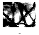
- FIG. 5 is a microscopic photograph of a media fiber structure at a focal depth in accordance with an implementation of the present disclosure.
- FIG. 6 is a microscopic photograph of a media fiber structure at a focal depth in accordance with an implementation of the present disclosure.
- FIG. 7 is a microscopic photograph of a media fiber structure at a focal depth in accordance with an implementation of the present disclosure.
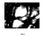
- FIG. 8 is a microscopic photograph of a media fiber structure at a focal depth in accordance with an implementation of the present disclosure.
- FIG. 9 is a microscopic photograph of a media fiber structure at a focal depth in accordance with an implementation of the present disclosure.
- FIG. 10 is a microscopic photograph of a media fiber structure at a focal depth in accordance with an implementation of the present disclosure.
- FIG. 11 is a microscopic photograph of a media fiber structure at a focal depth in accordance with an implementation of the present disclosure.
- FIG. 12 is a microscopic photograph of a media fiber structure at a focal depth in accordance with an implementation of the present disclosure.
- FIG. 13 is a microscopic photograph of a media fiber structure at a focal depth in accordance with an implementation of the present disclosure.
- Filtration systems utilize filtration media for the physical separation of components of a fluid stream from other components of the fluid stream.
- Filtration systems may employ air filtration media including relatively large fibers having a diameter measureable in micrometers (“micron fibers”) and comparatively smaller fibers having a diameter measureable in nanometers (“nano-fibers”) in an attempt to achieve improved filtration efficiency (e.g., the ability to capture more and smaller particles).
- the filtration structure may be configured to increase the surface area within a media for capturing particles by reducing the fiber size.
- the micron fibers can support webs of nano-fibers that can be produced directly onto the surface of preexisting fibrous substrates consisting of larger micron fibers, or layers of nano-fibers can be placed between layers of micron fiber media.
- Such configurations can employ nano-fibers that can be: a) extremely long, relatively continuous and although flexible and readily bent, they are for all intents and purposes, one dimensional (i.e., straight), having significant length as compared to their width or diameter, or b) short and very straight.
- filtration devices and methods employ micron fibers as a support body for smaller diameter nano-fibers attached thereto.
- the nano-fibers can have a crimped body structure with a discrete length. For instance, when these crimped nano-fibers having discrete length are attached to the micron fiber they entangle among themselves and also with, onto, and around, the micron fiber with firm attachment to form a modified fiber.
- the attachment of the nano-fibers to the micron fibers is accomplished via adhesion between the micron fibers and the nano-fibers.
- the attachment of the nano-fibers to the micron fibers is accomplished via electrostatic charge attraction and/or Van der Waals force attraction between the micron fibers and the nano-fibers.
- the attachment of the nano-fibers to the micron fibers is accomplished via mechanical entanglement of the nano-fibers onto and about the micron fibers.
- Numerous of these modified fibers e.g., the attached nano-fibers and micron fibers are configured for assembly into air filter media.
- the modified fiber structures described herein may be configured to form numerous micro-volumes, which may be smaller than pores formed solely by micron fibers, and which may maintain an open configuration, such as by resisting compaction.
- the crimped nano-fibers are distributed three-dimensionally in space relative to the supporting micron fiber (e.g., upstream and downstream distribution), which may increase fiber surface area and micro-volumes.
- the three-dimensional distribution also provides resistance against complete blockage of a particular portion of the filter media, such that a portion of fluid (e.g., air and/or other gases) can pass through the filter.
- Fiber is a flexible, threadlike object having a length at least 100 times its cross-sectional diameter in the case of a round fiber or 100 times its maximum cross-sectional dimension in the case of a non-round fiber.
- FIG. 3 provides a pictorial representation of a crimped nano-fiber.
- “Crimped Length” is the length, measured in a straight line, from one end of a fiber to the other end of the same fiber when the fiber is measured in a natural, relaxed and unrestrained condition.
- FIG. 3 provides a pictorial representation of the crimped length (D 1 ) of a crimped nano-fiber.
- “Straightened Length” is the length from one end of a fiber to the other end of the same fiber when the fiber is measured in a restrained manner under sufficient tensile loading to eliminate the crimp from the fiber.
- FIG. 4 provides a pictorial representation of a straightened length (D 2 ) of a nano-fiber.
- “Crimp Percent” is the ratio of the “crimped length” of a fiber compared to the “Straightened Length” of a fiber presented as a percent. To determine “Crimp Percent” divide the “Crimped Length” of a fiber by the “Straightened Length” of a fiber and multiply by 100.
- “High Loft Media” is a three-dimensional stabilized fibrous matrix in sheet form having significantly more air than fiber solids measured on a volume basis; furthermore having a length and a width, and a thickness measured perpendicular to the plane established by the measurement of width and length; the thickness being greater than the diameter of the micron fibers from which the media is made but less than five inches, the media utilized to remove gaseous, liquid, or solid contaminates from a fluid stream.
- Micro-volume is a three-dimensional space, defined by the nano-fibers of this disclosure. Furthermore, the nano-fibers simultaneously forming micro-pores arranged randomly on, in, and throughout the micro-volumes.
- the example fiber structure or substrate is a 1 ⁇ 2 inch thick high loft pad made from 6 denier fibers.
- the numeral 10 refers to the high loft fiber structure of this disclosure wherein nano-fibers 12 are attached to and entangled about the larger micron fibers 14 .
- the primary difference between FIG. 1 and FIG. 2 is that a larger amount of nano-fibers 12 are attached to the micron fibers 14 in FIG. 2 as compared to FIG. 1 .
- the nano-fibers 12 are entangled among themselves as well as attached to and entangle about the larger micron fibers 14 of the high loft filter media.
- the nano-fibers extend into the pores formed by the micron fibers 14 of the high loft media.
- FIGS. 1 and 2 illustrate, under magnification, the novel construction of the current disclosure wherein large fibers 14 of a traditional filter media have been augmented by the attachment of nano-fibers 12 .
- the nano-fibers 12 have affixed themselves to the larger fibers 14 as individual nano-fibers 12 and as small entangled tufts 16 of nano-fibers. These tufts also show the micro-volumes formed three-dimensionally by the entanglement of nano-fibers.
- Microscopic photographs of media fiber structures at various focal depths are provided in FIGS. 5 through 13 , where the images illustrate micron fibers having attached nano-fibers arranged in the typical fiber structures of the media. The microscopic photographs further illustrate the micro-volumes formed by the entangled nano-fibers.
- FIG. 2 also shows different sizes of fibers made into the novel fiber structure in a media.
- three fiber sizes large 14 , medium 15 , and small 12 . All these fibers may be synthetic or non-synthetic materials.
- the large and medium fibers are made to provide the structural strength of the media and the small fibers are made to attach to the large and medium fibers.
- the large and medium fibers used in a filtration media have diameters that may range from 2-1000 microns and their length may be in the order of one half to three inches.
- the diameter of the smaller fibers may range from 0.001-2 microns.
- the small fiber should be selected appropriately.
- the small fiber should be smaller than one-tenth of the diameter of the fiber to which it attaches. For example, if the large or medium fiber diameter is 20 microns, the small fibers attaching to it should be 2 microns or smaller.
- the length selection of the small fiber is related to the size of the pores formed by the large and medium fibers. First, the small fibers should have a length such that when crimped they attach to and entangle with each other about and around the diameter and along the length of the large and medium size fibers. Second, the length of the entangled small fibers should be such as to extend appropriately into the spaces of the pores formed by the large and medium fibers.
- the extension of the small fibers into the opening should not be longer than half the distance across the average size of pores. For example, if the average size of pores formed by the large and medium fibers is 1000 microns, then the extension of small fibers should be about 500 microns. It should be mentioned that the small fibers to be distributed in the media can be a composition of fibers with various diameters and lengths.
- a media composed of micron fibers 14 , 15 augmented by nano-sized fibers 12 permits capture by micron fibers 14 , 15 and the nano-fibers 12 of particles similar to the sizes of the capturing fibers.
- the nano-fibers 12 extend out into the openings between large fibers 14 , 15 effectively increasing the particle capturing efficiency by diffusion, interception and impaction with only minimal increase in pressure drop.
- the micro-volumes created by the entanglement of nano-fibers provide holding space for small captured particles, hence increasing the dust holding capacity of the filtration media.
- the extension of the nano-fibers 12 into the pores of a media formed by micron fibers 14 , 15 is three-dimensional.
- the fiber structures described herein can be made into a filter media.
- the filter media can be enhanced by the addition of adhesives (e.g., tackifiers), further enhancing the capturing efficiency with insignificant increase in pressure drop.
- the filter media retains structural strength, low material and manufacturing cost, durability, ease and flexibility of use, and so forth.
- the substantial amount of surface area and micro-volumes formed by the micron-size and nano-fibers can greatly improve the adsorption, absorption, and repellence of liquids.
- the substantial amount of surface area and huge number of micro-volumes formed by the micron fibers and nano-fibers can increase the capacity to retain and/or coalesce liquids.
- functional nano-particles are attached to the modified fiber structure (i.e., a filter media comprising micron-sized fibers with nano-fibers attached thereto).
- the functional nano-particles can include, for example, activated carbon deposited onto and/or attached to the modified fiber structure.
- the increased capacity for attachment of nano-particles such as activated carbon onto the micron fibers and nano-fibers can improve the gas absorption efficiency of the fibers due to the substantial increase in surface area throughout the whole media without significant increase in pressure drop.
- a filter media described herein is configured as a high loft media.
- the combination of novel fiber structure and high loft media of this disclosure provides a new type of filtration media which has high collection efficiency, low pressure drop, and high dust holding capacity that is easily adapted to existing manufacturing methods, products and applications and installations.
- the raw nano-fibers can be produced in several forms.
- the nano-fiber may be produced as long separated fibers.
- nano-fibers can be cut and crimped to obtain the desired length to diameter ratio.
- Another form of raw nano-fiber may consist of ground or milled pre-crimped nano-fibers dispersed in a liquid, which in a particular implementation is water.
- the nano-fiber and liquid mixture may be applied to micron fibers by liquid spray equipment.
- the crimped nano-fiber and liquid mixture may be used to make filter media using a wet laid process.
- Another form of the raw nano-fiber is dry clumps or chunks which are an aggregation of nano-fibers. Grinding may be utilized to reduce the size of the nano-fiber clumps prior to further processing to extract individual crimped nano-fibers for attaching to micron fibers of filter media.
- Methods for producing the product of the current disclosure include, but are not limited to:
- the crimped nano-fibers 12 attach themselves to the larger fibers 14 and 15 of the filtration media 10 via one or more of entanglement, adhesion, electrostatic charge, and van der Waals forces (i.e., generally describing the naturally occurring forces of physical attraction between small bodies), and the like. Crimped nano-fibers being small in diameter and relatively longer can easily entangle between themselves and onto the large micron fibers, as observed under a microscope. It should be noted that based on the method or methods chosen from the above production methods, the nano-fibers can be attached to all micron fibers or at specific depths or even to specific areas within the filtration media. In other words, the present disclosure provides for a filter media that is enhanced by nano-fibers in three dimensions (i.e. volumetric) as compared to filter media that is enhanced by nano-fiber web in two dimensions only (i.e., planar).
- the attractive forces between the crimped nano-fibers 12 and the large micron fibers 14 , 15 can be enhanced by electrostatically charging the dry nano-fibers 12 , the filtration media 10 , or both, during manufacturing.
- the electrostatic charging can occur, for example, by triboelectric charging, corona discharging, or other charging methods. Once the fibers touch each other, Van der Waals force comes into play, which further enhances the binding between fibers.
- the adhering forces between the crimped nano-fibers 12 and the larger micron fibers 14 , 15 can further be enhanced by coating them with an adhesive material (e.g., a tackifier) to provide a glue-like adhering force between the fibers.
- an adhesive material e.g., a tackifier
- the actions of adding tackifier and electrostatic charging not only serve to improve the attachment of the crimped nano-fiber 12 to the micron fiber 14 but further improve the filtration efficiency of the media therefore, even though the crimped nano-fiber 12 attaches satisfactorily to the micron fiber 14 without tackifier and electrostatic charging, tackifier and electrostatic charging can be applied during the filtration media manufacturing process simply to improve the filtration capability of the media.
- the physical state of crimped nano-fiber 12 during the process of attaching to the larger filter fibers 14 , 15 can be wet or dry.
- the final state of the crimped nano-fibers 12 in the fiber structures described herein can be wet or dry.
- the micron fibers and nano-fibers can be selectively made of hydrophilic or hydrophobic materials.
- the effective pore (i.e., micro-volume) size of the final filtration media can be controlled by selecting the appropriate sizes and combinations of the micron and crimped nano-fibers provides for even further refinement of the ability of the filter media to retain or repel liquids.
- fiber structures described herein are configured as a gradient density media in which the pore size decreases from the upstream to downstream to increase capture efficiency and dust holding capacity.
- Such a configuration allows for the application of various sizes and/or amounts of nano-fibers to the media at different depths from the upstream side.
- the upstream side of the media has lightest amount and/or largest size of attached nano-fibers while the downstream side has the heaviest amount and/or smallest size of attached nano-fibers.
- desired pore (i.e., micro-volume) sizes can be designed by stacking together layers of media to make a composite media in which each layer has a different amount and/or different size of nano-fibers.
Abstract
Description
-
- (1) Affixing the crimped nano-
fibers 12 to themicron fibers micron fiber - (2) Attaching the crimped nano-
fibers 12 to themicron fibers - (3) Attaching the crimped nano-
fibers 12 to themicron fibers filtration media 10, - (4) Treating the
filtration media 10 with crimped nano-fibers 12 after thefiltration media 10 is manufactured.
- (1) Affixing the crimped nano-
Claims (21)
Priority Applications (6)
| Application Number | Priority Date | Filing Date | Title |
|---|---|---|---|
| US14/075,635 US9522357B2 (en) | 2013-03-15 | 2013-11-08 | Filtration media fiber structure and method of making same |
| CA2845554A CA2845554C (en) | 2013-03-15 | 2014-03-11 | Filtration media fiber structure and method of making same |
| CN201410092627.4A CN104043285B (en) | 2013-03-15 | 2014-03-13 | Filter media fibers structure and its manufacture method |
| JP2014052361A JP6516971B2 (en) | 2013-03-15 | 2014-03-14 | Fiber structure of filtration medium and method for producing the same |
| EP14159791.4A EP2777796B8 (en) | 2013-03-15 | 2014-03-14 | Filtration media fiber structure and method of making same |
| US14/689,503 US9993761B2 (en) | 2013-03-15 | 2015-04-17 | Filtration media fiber structure and method of making same |
Applications Claiming Priority (2)
| Application Number | Priority Date | Filing Date | Title |
|---|---|---|---|
| US201361789309P | 2013-03-15 | 2013-03-15 | |
| US14/075,635 US9522357B2 (en) | 2013-03-15 | 2013-11-08 | Filtration media fiber structure and method of making same |
Related Child Applications (1)
| Application Number | Title | Priority Date | Filing Date |
|---|---|---|---|
| US14/689,503 Continuation-In-Part US9993761B2 (en) | 2013-03-15 | 2015-04-17 | Filtration media fiber structure and method of making same |
Publications (2)
| Publication Number | Publication Date |
|---|---|
| US20140260990A1 US20140260990A1 (en) | 2014-09-18 |
| US9522357B2 true US9522357B2 (en) | 2016-12-20 |
Family
ID=50382217
Family Applications (1)
| Application Number | Title | Priority Date | Filing Date |
|---|---|---|---|
| US14/075,635 Active 2034-08-15 US9522357B2 (en) | 2013-03-15 | 2013-11-08 | Filtration media fiber structure and method of making same |
Country Status (5)
| Country | Link |
|---|---|
| US (1) | US9522357B2 (en) |
| EP (1) | EP2777796B8 (en) |
| JP (1) | JP6516971B2 (en) |
| CN (1) | CN104043285B (en) |
| CA (1) | CA2845554C (en) |
Cited By (2)
| Publication number | Priority date | Publication date | Assignee | Title |
|---|---|---|---|---|
| US20180099238A1 (en) * | 2016-10-07 | 2018-04-12 | Pure Gravity Filtration Systems, Llc | Filter pad |
| US10913022B2 (en) | 2017-03-29 | 2021-02-09 | Knowlton Technologies, Llc | Process for utilizing a high efficiency synthetic filter media |
Families Citing this family (20)
| Publication number | Priority date | Publication date | Assignee | Title |
|---|---|---|---|---|
| US9191203B2 (en) | 2013-08-06 | 2015-11-17 | Bedrock Automation Platforms Inc. | Secure industrial control system |
| US9437967B2 (en) | 2011-12-30 | 2016-09-06 | Bedrock Automation Platforms, Inc. | Electromagnetic connector for an industrial control system |
| US10834820B2 (en) | 2013-08-06 | 2020-11-10 | Bedrock Automation Platforms Inc. | Industrial control system cable |
| US9600434B1 (en) | 2011-12-30 | 2017-03-21 | Bedrock Automation Platforms, Inc. | Switch fabric having a serial communications interface and a parallel communications interface |
| US11314854B2 (en) | 2011-12-30 | 2022-04-26 | Bedrock Automation Platforms Inc. | Image capture devices for a secure industrial control system |
| US8971072B2 (en) | 2011-12-30 | 2015-03-03 | Bedrock Automation Platforms Inc. | Electromagnetic connector for an industrial control system |
| US10834094B2 (en) | 2013-08-06 | 2020-11-10 | Bedrock Automation Platforms Inc. | Operator action authentication in an industrial control system |
| US11144630B2 (en) | 2011-12-30 | 2021-10-12 | Bedrock Automation Platforms Inc. | Image capture devices for a secure industrial control system |
| US8868813B2 (en) | 2011-12-30 | 2014-10-21 | Bedrock Automation Platforms Inc. | Communications control system with a serial communications interface and a parallel communications interface |
| US9727511B2 (en) | 2011-12-30 | 2017-08-08 | Bedrock Automation Platforms Inc. | Input/output module with multi-channel switching capability |
| US10613567B2 (en) | 2013-08-06 | 2020-04-07 | Bedrock Automation Platforms Inc. | Secure power supply for an industrial control system |
| JP7005124B2 (en) * | 2015-04-17 | 2022-01-21 | プロダクツ・アンリミテッド・インコーポレイテッド | Filtration medium fiber structure and its manufacturing method |
| US10159926B2 (en) * | 2015-09-11 | 2018-12-25 | Ultra Small Fibers, LLC | Tunable nanofiber filter media and filter devices |
| JP6721919B2 (en) * | 2016-03-23 | 2020-07-15 | 北越コーポレーション株式会社 | Filter material for air filter |
| CN106377948A (en) * | 2016-08-30 | 2017-02-08 | 康俊平 | Nano fiber coating layer super-hydrophobic self-cleaning air filter core and manufacturing method thereof |
| CN107051016B (en) * | 2017-03-09 | 2023-11-10 | 中国石油大学(北京) | Composite modified gas-liquid coalescing filter |
| JPWO2021039980A1 (en) * | 2019-08-30 | 2021-03-04 | ||
| CN112057951B (en) * | 2020-08-25 | 2021-09-21 | 东华大学 | Three-dimensional non-woven filter material with micro-nano overlapped structure and preparation method thereof |
| US20230323055A1 (en) * | 2022-04-08 | 2023-10-12 | Delstar Technologies, Inc. | Systems and methods for retaining nanoparticles within nonwoven material |
| US20230321568A1 (en) * | 2022-04-08 | 2023-10-12 | Delstar Technologies, Inc. | Filtration media and filters |
Citations (27)
| Publication number | Priority date | Publication date | Assignee | Title |
|---|---|---|---|---|
| US3353682A (en) * | 1966-02-28 | 1967-11-21 | Pall Corp | Fluid-permeable fibrous multilayer materials and process of making the same |
| US3475527A (en) * | 1967-12-11 | 1969-10-28 | Monsanto Co | Process for destroying melt crystalline order in fiber-forming polymers |
| US3476635A (en) * | 1966-07-11 | 1969-11-04 | American Air Filter Co | Graduated density filamentous mat |
| US4904343A (en) * | 1985-04-23 | 1990-02-27 | American Cyanamid Company | Non-woven activated carbon fabric |
| US5221573A (en) * | 1991-12-30 | 1993-06-22 | Kem-Wove, Inc. | Adsorbent textile product |
| US5330638A (en) * | 1990-05-22 | 1994-07-19 | Filtercorp Partners L.P. | Commercial filtering system |
| US5376278A (en) * | 1993-07-01 | 1994-12-27 | The Graver Company | Filter and a method for separating charged particles from a liquid stream |
| US5641343A (en) * | 1996-01-25 | 1997-06-24 | Hmi Industries, Inc. | Room air cleaner |
| US5674339A (en) * | 1992-11-18 | 1997-10-07 | Hoechst Celanese Corporation | Process for fibrous structure containing immobilized particulate matter |
| US20030073370A1 (en) * | 2001-08-14 | 2003-04-17 | Strommen Michael R. | Flexible adsorbent filter |
| US20030148097A1 (en) * | 2002-01-08 | 2003-08-07 | Futaba Corporation | Method for preparing nano-carbon fiber and nano-carbon fiber |
| US20030168401A1 (en) * | 2002-01-31 | 2003-09-11 | Koslow Evan E. | Microporous filter media, filtration systems containing same, and methods of making and using |
| US20040038013A1 (en) * | 2002-08-20 | 2004-02-26 | Schaefer James W. | Fiber containing filter media |
| US20040211160A1 (en) * | 2002-05-16 | 2004-10-28 | Branofilter Gmbh | Multi-layer filter structure and use of a multi-layer filter structure |
| US20040253371A1 (en) * | 2003-06-10 | 2004-12-16 | Janney Mark A. | Filter and method of fabricating |
| US6838005B2 (en) | 2001-06-22 | 2005-01-04 | Frederick Tepper | Nanosize electropositive fibrous adsorbent |
| US20050026526A1 (en) * | 2003-07-30 | 2005-02-03 | Verdegan Barry M. | High performance filter media with internal nanofiber structure and manufacturing methodology |
| US20060068668A1 (en) * | 2004-09-27 | 2006-03-30 | Cornell Research Foundation, Inc. | Microfiber supported nanofiber membrane |
| US20070175196A1 (en) * | 2005-09-12 | 2007-08-02 | Argonide Corporation | Drinking water filtration device |
| US20080020193A1 (en) * | 2006-07-24 | 2008-01-24 | Jang Bor Z | Hybrid fiber tows containning both nano-fillers and continuous fibers, hybrid composites, and their production processes |
| US20080072551A1 (en) * | 2002-10-28 | 2008-03-27 | Bilal Zuberi | Highly porous mullite particulate filter substrate |
| US7390760B1 (en) * | 2004-11-02 | 2008-06-24 | Kimberly-Clark Worldwide, Inc. | Composite nanofiber materials and methods for making same |
| US20080264259A1 (en) * | 2007-04-26 | 2008-10-30 | Leung Wallace W | Nanofiber filter facemasks and cabin filters |
| US20090266759A1 (en) * | 2008-04-24 | 2009-10-29 | Clarcor Inc. | Integrated nanofiber filter media |
| US20100122515A1 (en) * | 2008-11-18 | 2010-05-20 | Han-Wen Kuo | Poison-filter material and production method thereof |
| WO2011133394A1 (en) | 2010-04-22 | 2011-10-27 | 3M Innovative Properties Company | Nonwoven nanofiber webs containing chemically active particulates and methods of making and using same |
| US8366797B2 (en) | 2000-09-05 | 2013-02-05 | Donaldson Company, Inc. | Fine fiber media layer |
Family Cites Families (9)
| Publication number | Priority date | Publication date | Assignee | Title |
|---|---|---|---|---|
| JPH03279452A (en) * | 1990-03-23 | 1991-12-10 | Asahi Chem Ind Co Ltd | High-strength nonwoven sheet |
| JP3326808B2 (en) * | 1992-02-12 | 2002-09-24 | チッソ株式会社 | filter |
| JP4486562B2 (en) * | 2005-08-08 | 2010-06-23 | 東洋紡績株式会社 | Filter medium and air cleaner element for internal combustion engine air cleaner |
| WO2007095335A2 (en) * | 2006-02-13 | 2007-08-23 | Donaldson Company, Inc. | Filter web comprising fine fiber and reactive, adsorptive or absorptive particulate |
| JP2009150005A (en) * | 2007-12-19 | 2009-07-09 | Kuraray Co Ltd | Fibrous structure, its use, and production method |
| WO2009085679A1 (en) * | 2007-12-28 | 2009-07-09 | 3M Innovative Properties Company | Composite nonwoven fibrous webs and methods of making and using the same |
| CN101509155B (en) * | 2009-03-13 | 2012-05-23 | 东华大学 | Dyeable fine denier polypropylene fibers of clay soil/polyolefin particle and preparation method thereof |
| JP5284889B2 (en) * | 2009-06-24 | 2013-09-11 | 帝人株式会社 | Fiber products |
| US9771675B2 (en) * | 2010-07-07 | 2017-09-26 | 3M Innovative Properties Company | Patterned air-laid nonwoven fibrous webs and methods of making and using same |
-
2013
- 2013-11-08 US US14/075,635 patent/US9522357B2/en active Active
-
2014
- 2014-03-11 CA CA2845554A patent/CA2845554C/en active Active
- 2014-03-13 CN CN201410092627.4A patent/CN104043285B/en active Active
- 2014-03-14 EP EP14159791.4A patent/EP2777796B8/en active Active
- 2014-03-14 JP JP2014052361A patent/JP6516971B2/en active Active
Patent Citations (28)
| Publication number | Priority date | Publication date | Assignee | Title |
|---|---|---|---|---|
| US3353682A (en) * | 1966-02-28 | 1967-11-21 | Pall Corp | Fluid-permeable fibrous multilayer materials and process of making the same |
| US3476635A (en) * | 1966-07-11 | 1969-11-04 | American Air Filter Co | Graduated density filamentous mat |
| US3475527A (en) * | 1967-12-11 | 1969-10-28 | Monsanto Co | Process for destroying melt crystalline order in fiber-forming polymers |
| US4904343A (en) * | 1985-04-23 | 1990-02-27 | American Cyanamid Company | Non-woven activated carbon fabric |
| US5330638A (en) * | 1990-05-22 | 1994-07-19 | Filtercorp Partners L.P. | Commercial filtering system |
| US5221573A (en) * | 1991-12-30 | 1993-06-22 | Kem-Wove, Inc. | Adsorbent textile product |
| US5674339A (en) * | 1992-11-18 | 1997-10-07 | Hoechst Celanese Corporation | Process for fibrous structure containing immobilized particulate matter |
| US5376278A (en) * | 1993-07-01 | 1994-12-27 | The Graver Company | Filter and a method for separating charged particles from a liquid stream |
| US5641343A (en) * | 1996-01-25 | 1997-06-24 | Hmi Industries, Inc. | Room air cleaner |
| US8366797B2 (en) | 2000-09-05 | 2013-02-05 | Donaldson Company, Inc. | Fine fiber media layer |
| US6838005B2 (en) | 2001-06-22 | 2005-01-04 | Frederick Tepper | Nanosize electropositive fibrous adsorbent |
| US20030073370A1 (en) * | 2001-08-14 | 2003-04-17 | Strommen Michael R. | Flexible adsorbent filter |
| US20030148097A1 (en) * | 2002-01-08 | 2003-08-07 | Futaba Corporation | Method for preparing nano-carbon fiber and nano-carbon fiber |
| US20030168401A1 (en) * | 2002-01-31 | 2003-09-11 | Koslow Evan E. | Microporous filter media, filtration systems containing same, and methods of making and using |
| US20040211160A1 (en) * | 2002-05-16 | 2004-10-28 | Branofilter Gmbh | Multi-layer filter structure and use of a multi-layer filter structure |
| US20040038013A1 (en) * | 2002-08-20 | 2004-02-26 | Schaefer James W. | Fiber containing filter media |
| US20080072551A1 (en) * | 2002-10-28 | 2008-03-27 | Bilal Zuberi | Highly porous mullite particulate filter substrate |
| US6998009B2 (en) * | 2003-06-10 | 2006-02-14 | Ut-Battelle, Llc | Filter and method of fabricating |
| US20040253371A1 (en) * | 2003-06-10 | 2004-12-16 | Janney Mark A. | Filter and method of fabricating |
| US20050026526A1 (en) * | 2003-07-30 | 2005-02-03 | Verdegan Barry M. | High performance filter media with internal nanofiber structure and manufacturing methodology |
| US20060068668A1 (en) * | 2004-09-27 | 2006-03-30 | Cornell Research Foundation, Inc. | Microfiber supported nanofiber membrane |
| US7390760B1 (en) * | 2004-11-02 | 2008-06-24 | Kimberly-Clark Worldwide, Inc. | Composite nanofiber materials and methods for making same |
| US20070175196A1 (en) * | 2005-09-12 | 2007-08-02 | Argonide Corporation | Drinking water filtration device |
| US20080020193A1 (en) * | 2006-07-24 | 2008-01-24 | Jang Bor Z | Hybrid fiber tows containning both nano-fillers and continuous fibers, hybrid composites, and their production processes |
| US20080264259A1 (en) * | 2007-04-26 | 2008-10-30 | Leung Wallace W | Nanofiber filter facemasks and cabin filters |
| US20090266759A1 (en) * | 2008-04-24 | 2009-10-29 | Clarcor Inc. | Integrated nanofiber filter media |
| US20100122515A1 (en) * | 2008-11-18 | 2010-05-20 | Han-Wen Kuo | Poison-filter material and production method thereof |
| WO2011133394A1 (en) | 2010-04-22 | 2011-10-27 | 3M Innovative Properties Company | Nonwoven nanofiber webs containing chemically active particulates and methods of making and using same |
Cited By (4)
| Publication number | Priority date | Publication date | Assignee | Title |
|---|---|---|---|---|
| US20180099238A1 (en) * | 2016-10-07 | 2018-04-12 | Pure Gravity Filtration Systems, Llc | Filter pad |
| US10913022B2 (en) | 2017-03-29 | 2021-02-09 | Knowlton Technologies, Llc | Process for utilizing a high efficiency synthetic filter media |
| US10981096B2 (en) | 2017-03-29 | 2021-04-20 | Knowlton Technologies, Llc | Process for making high efficiency synthetic filter media |
| US11547963B2 (en) | 2017-03-29 | 2023-01-10 | Knowlton Technologies, Llc | High efficiency synthetic filter media |
Also Published As
| Publication number | Publication date |
|---|---|
| JP6516971B2 (en) | 2019-05-22 |
| EP2777796A1 (en) | 2014-09-17 |
| EP2777796B8 (en) | 2016-07-13 |
| CA2845554C (en) | 2021-06-08 |
| US20140260990A1 (en) | 2014-09-18 |
| CN104043285B (en) | 2018-01-12 |
| JP2014205943A (en) | 2014-10-30 |
| CA2845554A1 (en) | 2014-09-15 |
| EP2777796B1 (en) | 2016-05-11 |
| CN104043285A (en) | 2014-09-17 |
Similar Documents
| Publication | Publication Date | Title |
|---|---|---|
| US9522357B2 (en) | Filtration media fiber structure and method of making same | |
| US10155187B2 (en) | Filter media with a multi-layer structure | |
| US8939295B2 (en) | Multi-layer, fluid transmissive fiber structures containing nanofibers and a method of manufacturing such structures | |
| US20200215471A1 (en) | Filter media including oriented fibers | |
| US9993761B2 (en) | Filtration media fiber structure and method of making same | |
| JP5346301B2 (en) | Wave filter material and filter element | |
| WO2007126539A1 (en) | High capacity filter medium | |
| JP2011025238A (en) | High performance gas turbine inlet filter (hepa) using membrane media | |
| IL243328A (en) | Filter medium | |
| EP3081277B1 (en) | Filtration media fiber structure and method of making same | |
| JP2024041800A (en) | Filtration media with improved dust loading | |
| JP7443242B2 (en) | Filter material for oil filters for automatic transmissions |
Legal Events
| Date | Code | Title | Description |
|---|---|---|---|
| AS | Assignment |
Owner name: PRODUCTS UNLIMITED, INC., NEBRASKA Free format text: ASSIGNMENT OF ASSIGNORS INTEREST;ASSIGNORS:BEIER, SCOTT B.;POSPISAL, GARY;REEL/FRAME:032312/0473 Effective date: 20140227 Owner name: LMS TECHNOLOGIES, INC., MINNESOTA Free format text: ASSIGNMENT OF ASSIGNORS INTEREST;ASSIGNORS:KWOK, KUI-CHIU;VATINE, AL;REEL/FRAME:032363/0567 Effective date: 20140227 |
|
| STCF | Information on status: patent grant |
Free format text: PATENTED CASE |
|
| MAFP | Maintenance fee payment |
Free format text: PAYMENT OF MAINTENANCE FEE, 4TH YR, SMALL ENTITY (ORIGINAL EVENT CODE: M2551); ENTITY STATUS OF PATENT OWNER: SMALL ENTITY Year of fee payment: 4 |
|
| AS | Assignment |
Owner name: COMPLETE FILTER MANAGEMENT LLC, NEBRASKA Free format text: ASSIGNMENT OF ASSIGNORS INTEREST;ASSIGNOR:PRODUCTS UNLIMITED, INC.;REEL/FRAME:055840/0106 Effective date: 20210405 |