US9508886B2 - Method for making a crystalline silicon solar cell substrate utilizing flat top laser beam - Google Patents
Method for making a crystalline silicon solar cell substrate utilizing flat top laser beam Download PDFInfo
- Publication number
- US9508886B2 US9508886B2 US13/271,212 US201113271212A US9508886B2 US 9508886 B2 US9508886 B2 US 9508886B2 US 201113271212 A US201113271212 A US 201113271212A US 9508886 B2 US9508886 B2 US 9508886B2
- Authority
- US
- United States
- Prior art keywords
- flat top
- laser beam
- silicon
- laser
- overlayer
- Prior art date
- Legal status (The legal status is an assumption and is not a legal conclusion. Google has not performed a legal analysis and makes no representation as to the accuracy of the status listed.)
- Expired - Fee Related
Links
- 238000000034 method Methods 0.000 title claims abstract description 136
- 239000000758 substrate Substances 0.000 title claims abstract description 76
- 229910021419 crystalline silicon Inorganic materials 0.000 title claims abstract description 41
- 229910052710 silicon Inorganic materials 0.000 claims abstract description 97
- 239000010703 silicon Substances 0.000 claims abstract description 97
- XUIMIQQOPSSXEZ-UHFFFAOYSA-N Silicon Chemical compound [Si] XUIMIQQOPSSXEZ-UHFFFAOYSA-N 0.000 claims abstract description 96
- 238000000608 laser ablation Methods 0.000 claims abstract description 35
- 238000000151 deposition Methods 0.000 claims description 13
- VYPSYNLAJGMNEJ-UHFFFAOYSA-N Silicium dioxide Chemical compound O=[Si]=O VYPSYNLAJGMNEJ-UHFFFAOYSA-N 0.000 claims description 10
- 229910052814 silicon oxide Inorganic materials 0.000 claims description 4
- 230000010354 integration Effects 0.000 claims description 3
- 230000001678 irradiating effect Effects 0.000 claims description 3
- 230000008569 process Effects 0.000 description 72
- 229910052751 metal Inorganic materials 0.000 description 53
- 239000002184 metal Substances 0.000 description 53
- 241001270131 Agaricus moelleri Species 0.000 description 49
- 238000002679 ablation Methods 0.000 description 48
- 238000012545 processing Methods 0.000 description 37
- 238000002955 isolation Methods 0.000 description 21
- 230000008901 benefit Effects 0.000 description 15
- 238000004519 manufacturing process Methods 0.000 description 14
- 230000035515 penetration Effects 0.000 description 13
- 238000010586 diagram Methods 0.000 description 12
- 230000008021 deposition Effects 0.000 description 11
- 239000010408 film Substances 0.000 description 11
- 238000001465 metallisation Methods 0.000 description 11
- 229910021417 amorphous silicon Inorganic materials 0.000 description 10
- 239000010409 thin film Substances 0.000 description 10
- 235000012431 wafers Nutrition 0.000 description 10
- 238000011065 in-situ storage Methods 0.000 description 9
- 229910052782 aluminium Inorganic materials 0.000 description 8
- 229910052581 Si3N4 Inorganic materials 0.000 description 7
- XAGFODPZIPBFFR-UHFFFAOYSA-N aluminium Chemical compound [Al] XAGFODPZIPBFFR-UHFFFAOYSA-N 0.000 description 7
- 230000015572 biosynthetic process Effects 0.000 description 7
- 238000002161 passivation Methods 0.000 description 7
- 238000000059 patterning Methods 0.000 description 7
- 229910021426 porous silicon Inorganic materials 0.000 description 7
- HQVNEWCFYHHQES-UHFFFAOYSA-N silicon nitride Chemical compound N12[Si]34N5[Si]62N3[Si]51N64 HQVNEWCFYHHQES-UHFFFAOYSA-N 0.000 description 7
- 239000000463 material Substances 0.000 description 6
- 238000000926 separation method Methods 0.000 description 6
- 239000002019 doping agent Substances 0.000 description 5
- 239000004065 semiconductor Substances 0.000 description 5
- 238000001505 atmospheric-pressure chemical vapour deposition Methods 0.000 description 4
- 229910021421 monocrystalline silicon Inorganic materials 0.000 description 4
- 238000003672 processing method Methods 0.000 description 4
- 230000006798 recombination Effects 0.000 description 4
- 238000005215 recombination Methods 0.000 description 4
- 230000009467 reduction Effects 0.000 description 4
- ZOXJGFHDIHLPTG-UHFFFAOYSA-N Boron Chemical compound [B] ZOXJGFHDIHLPTG-UHFFFAOYSA-N 0.000 description 3
- 229910052796 boron Inorganic materials 0.000 description 3
- 230000015556 catabolic process Effects 0.000 description 3
- 238000004140 cleaning Methods 0.000 description 3
- 239000004020 conductor Substances 0.000 description 3
- 229910052802 copper Inorganic materials 0.000 description 3
- 239000010949 copper Substances 0.000 description 3
- 238000006731 degradation reaction Methods 0.000 description 3
- 230000032798 delamination Effects 0.000 description 3
- 238000009792 diffusion process Methods 0.000 description 3
- 239000007789 gas Substances 0.000 description 3
- 238000010438 heat treatment Methods 0.000 description 3
- BHEPBYXIRTUNPN-UHFFFAOYSA-N hydridophosphorus(.) (triplet) Chemical compound [PH] BHEPBYXIRTUNPN-UHFFFAOYSA-N 0.000 description 3
- 230000001788 irregular Effects 0.000 description 3
- 238000001459 lithography Methods 0.000 description 3
- 230000003647 oxidation Effects 0.000 description 3
- 238000007254 oxidation reaction Methods 0.000 description 3
- 235000012239 silicon dioxide Nutrition 0.000 description 3
- 239000000377 silicon dioxide Substances 0.000 description 3
- RYGMFSIKBFXOCR-UHFFFAOYSA-N Copper Chemical compound [Cu] RYGMFSIKBFXOCR-UHFFFAOYSA-N 0.000 description 2
- 238000000231 atomic layer deposition Methods 0.000 description 2
- 230000003247 decreasing effect Effects 0.000 description 2
- 238000013461 design Methods 0.000 description 2
- 238000001035 drying Methods 0.000 description 2
- 230000000694 effects Effects 0.000 description 2
- 238000000407 epitaxy Methods 0.000 description 2
- 230000006872 improvement Effects 0.000 description 2
- 230000008018 melting Effects 0.000 description 2
- 238000002844 melting Methods 0.000 description 2
- 230000001590 oxidative effect Effects 0.000 description 2
- 238000005240 physical vapour deposition Methods 0.000 description 2
- 238000007493 shaping process Methods 0.000 description 2
- 239000000126 substance Substances 0.000 description 2
- UFHFLCQGNIYNRP-UHFFFAOYSA-N Hydrogen Chemical compound [H][H] UFHFLCQGNIYNRP-UHFFFAOYSA-N 0.000 description 1
- OAICVXFJPJFONN-UHFFFAOYSA-N Phosphorus Chemical compound [P] OAICVXFJPJFONN-UHFFFAOYSA-N 0.000 description 1
- 229910004205 SiNX Inorganic materials 0.000 description 1
- ATJFFYVFTNAWJD-UHFFFAOYSA-N Tin Chemical compound [Sn] ATJFFYVFTNAWJD-UHFFFAOYSA-N 0.000 description 1
- 239000006096 absorbing agent Substances 0.000 description 1
- 238000010521 absorption reaction Methods 0.000 description 1
- 238000009825 accumulation Methods 0.000 description 1
- 238000000137 annealing Methods 0.000 description 1
- 238000013459 approach Methods 0.000 description 1
- 239000005388 borosilicate glass Substances 0.000 description 1
- 239000011449 brick Substances 0.000 description 1
- 238000005336 cracking Methods 0.000 description 1
- 230000002939 deleterious effect Effects 0.000 description 1
- 238000005137 deposition process Methods 0.000 description 1
- 239000003989 dielectric material Substances 0.000 description 1
- 230000003467 diminishing effect Effects 0.000 description 1
- 238000007772 electroless plating Methods 0.000 description 1
- 238000009713 electroplating Methods 0.000 description 1
- 238000005516 engineering process Methods 0.000 description 1
- 238000001704 evaporation Methods 0.000 description 1
- 230000008020 evaporation Effects 0.000 description 1
- 229910052739 hydrogen Inorganic materials 0.000 description 1
- 239000001257 hydrogen Substances 0.000 description 1
- 238000002513 implantation Methods 0.000 description 1
- 239000000155 melt Substances 0.000 description 1
- 238000005459 micromachining Methods 0.000 description 1
- 238000012986 modification Methods 0.000 description 1
- 230000004048 modification Effects 0.000 description 1
- HBVFXTAPOLSOPB-UHFFFAOYSA-N nickel vanadium Chemical compound [V].[Ni] HBVFXTAPOLSOPB-UHFFFAOYSA-N 0.000 description 1
- 230000003287 optical effect Effects 0.000 description 1
- 238000000879 optical micrograph Methods 0.000 description 1
- 230000001151 other effect Effects 0.000 description 1
- TWNQGVIAIRXVLR-UHFFFAOYSA-N oxo(oxoalumanyloxy)alumane Chemical compound O=[Al]O[Al]=O TWNQGVIAIRXVLR-UHFFFAOYSA-N 0.000 description 1
- 229910052698 phosphorus Inorganic materials 0.000 description 1
- 239000011574 phosphorus Substances 0.000 description 1
- 229920002120 photoresistant polymer Polymers 0.000 description 1
- 238000000623 plasma-assisted chemical vapour deposition Methods 0.000 description 1
- 238000007747 plating Methods 0.000 description 1
- 231100000614 poison Toxicity 0.000 description 1
- 230000007096 poisonous effect Effects 0.000 description 1
- 238000002360 preparation method Methods 0.000 description 1
- 230000005855 radiation Effects 0.000 description 1
- 238000001953 recrystallisation Methods 0.000 description 1
- 230000002787 reinforcement Effects 0.000 description 1
- 150000003376 silicon Chemical class 0.000 description 1
- 230000003746 surface roughness Effects 0.000 description 1
- 238000012360 testing method Methods 0.000 description 1
- 238000001039 wet etching Methods 0.000 description 1
Images


Classifications
-
- H—ELECTRICITY
- H01—ELECTRIC ELEMENTS
- H01L—SEMICONDUCTOR DEVICES NOT COVERED BY CLASS H10
- H01L31/00—Semiconductor devices sensitive to infrared radiation, light, electromagnetic radiation of shorter wavelength or corpuscular radiation and specially adapted either for the conversion of the energy of such radiation into electrical energy or for the control of electrical energy by such radiation; Processes or apparatus specially adapted for the manufacture or treatment thereof or of parts thereof; Details thereof
- H01L31/04—Semiconductor devices sensitive to infrared radiation, light, electromagnetic radiation of shorter wavelength or corpuscular radiation and specially adapted either for the conversion of the energy of such radiation into electrical energy or for the control of electrical energy by such radiation; Processes or apparatus specially adapted for the manufacture or treatment thereof or of parts thereof; Details thereof adapted as photovoltaic [PV] conversion devices
- H01L31/042—PV modules or arrays of single PV cells
- H01L31/0445—PV modules or arrays of single PV cells including thin film solar cells, e.g. single thin film a-Si, CIS or CdTe solar cells
- H01L31/046—PV modules composed of a plurality of thin film solar cells deposited on the same substrate
- H01L31/0463—PV modules composed of a plurality of thin film solar cells deposited on the same substrate characterised by special patterning methods to connect the PV cells in a module, e.g. laser cutting of the conductive or active layers
-
- H—ELECTRICITY
- H01—ELECTRIC ELEMENTS
- H01L—SEMICONDUCTOR DEVICES NOT COVERED BY CLASS H10
- H01L31/00—Semiconductor devices sensitive to infrared radiation, light, electromagnetic radiation of shorter wavelength or corpuscular radiation and specially adapted either for the conversion of the energy of such radiation into electrical energy or for the control of electrical energy by such radiation; Processes or apparatus specially adapted for the manufacture or treatment thereof or of parts thereof; Details thereof
- H01L31/18—Processes or apparatus specially adapted for the manufacture or treatment of these devices or of parts thereof
-
- B—PERFORMING OPERATIONS; TRANSPORTING
- B23—MACHINE TOOLS; METAL-WORKING NOT OTHERWISE PROVIDED FOR
- B23K—SOLDERING OR UNSOLDERING; WELDING; CLADDING OR PLATING BY SOLDERING OR WELDING; CUTTING BY APPLYING HEAT LOCALLY, e.g. FLAME CUTTING; WORKING BY LASER BEAM
- B23K26/00—Working by laser beam, e.g. welding, cutting or boring
- B23K26/36—Removing material
- B23K26/362—Laser etching
- B23K26/364—Laser etching for making a groove or trench, e.g. for scribing a break initiation groove
-
- B—PERFORMING OPERATIONS; TRANSPORTING
- B23—MACHINE TOOLS; METAL-WORKING NOT OTHERWISE PROVIDED FOR
- B23K—SOLDERING OR UNSOLDERING; WELDING; CLADDING OR PLATING BY SOLDERING OR WELDING; CUTTING BY APPLYING HEAT LOCALLY, e.g. FLAME CUTTING; WORKING BY LASER BEAM
- B23K26/00—Working by laser beam, e.g. welding, cutting or boring
- B23K26/36—Removing material
- B23K26/40—Removing material taking account of the properties of the material involved
-
- H—ELECTRICITY
- H01—ELECTRIC ELEMENTS
- H01L—SEMICONDUCTOR DEVICES NOT COVERED BY CLASS H10
- H01L31/00—Semiconductor devices sensitive to infrared radiation, light, electromagnetic radiation of shorter wavelength or corpuscular radiation and specially adapted either for the conversion of the energy of such radiation into electrical energy or for the control of electrical energy by such radiation; Processes or apparatus specially adapted for the manufacture or treatment thereof or of parts thereof; Details thereof
- H01L31/02—Details
- H01L31/0216—Coatings
- H01L31/02161—Coatings for devices characterised by at least one potential jump barrier or surface barrier
- H01L31/02167—Coatings for devices characterised by at least one potential jump barrier or surface barrier for solar cells
- H01L31/02168—Coatings for devices characterised by at least one potential jump barrier or surface barrier for solar cells the coatings being antireflective or having enhancing optical properties for the solar cells
-
- H—ELECTRICITY
- H01—ELECTRIC ELEMENTS
- H01L—SEMICONDUCTOR DEVICES NOT COVERED BY CLASS H10
- H01L31/00—Semiconductor devices sensitive to infrared radiation, light, electromagnetic radiation of shorter wavelength or corpuscular radiation and specially adapted either for the conversion of the energy of such radiation into electrical energy or for the control of electrical energy by such radiation; Processes or apparatus specially adapted for the manufacture or treatment thereof or of parts thereof; Details thereof
- H01L31/02—Details
- H01L31/0224—Electrodes
- H01L31/022408—Electrodes for devices characterised by at least one potential jump barrier or surface barrier
- H01L31/022425—Electrodes for devices characterised by at least one potential jump barrier or surface barrier for solar cells
- H01L31/022441—Electrode arrangements specially adapted for back-contact solar cells
-
- H—ELECTRICITY
- H01—ELECTRIC ELEMENTS
- H01L—SEMICONDUCTOR DEVICES NOT COVERED BY CLASS H10
- H01L31/00—Semiconductor devices sensitive to infrared radiation, light, electromagnetic radiation of shorter wavelength or corpuscular radiation and specially adapted either for the conversion of the energy of such radiation into electrical energy or for the control of electrical energy by such radiation; Processes or apparatus specially adapted for the manufacture or treatment thereof or of parts thereof; Details thereof
- H01L31/02—Details
- H01L31/0236—Special surface textures
- H01L31/02363—Special surface textures of the semiconductor body itself, e.g. textured active layers
-
- H—ELECTRICITY
- H01—ELECTRIC ELEMENTS
- H01L—SEMICONDUCTOR DEVICES NOT COVERED BY CLASS H10
- H01L31/00—Semiconductor devices sensitive to infrared radiation, light, electromagnetic radiation of shorter wavelength or corpuscular radiation and specially adapted either for the conversion of the energy of such radiation into electrical energy or for the control of electrical energy by such radiation; Processes or apparatus specially adapted for the manufacture or treatment thereof or of parts thereof; Details thereof
- H01L31/0248—Semiconductor devices sensitive to infrared radiation, light, electromagnetic radiation of shorter wavelength or corpuscular radiation and specially adapted either for the conversion of the energy of such radiation into electrical energy or for the control of electrical energy by such radiation; Processes or apparatus specially adapted for the manufacture or treatment thereof or of parts thereof; Details thereof characterised by their semiconductor bodies
- H01L31/0352—Semiconductor devices sensitive to infrared radiation, light, electromagnetic radiation of shorter wavelength or corpuscular radiation and specially adapted either for the conversion of the energy of such radiation into electrical energy or for the control of electrical energy by such radiation; Processes or apparatus specially adapted for the manufacture or treatment thereof or of parts thereof; Details thereof characterised by their semiconductor bodies characterised by their shape or by the shapes, relative sizes or disposition of the semiconductor regions
- H01L31/035272—Semiconductor devices sensitive to infrared radiation, light, electromagnetic radiation of shorter wavelength or corpuscular radiation and specially adapted either for the conversion of the energy of such radiation into electrical energy or for the control of electrical energy by such radiation; Processes or apparatus specially adapted for the manufacture or treatment thereof or of parts thereof; Details thereof characterised by their semiconductor bodies characterised by their shape or by the shapes, relative sizes or disposition of the semiconductor regions characterised by at least one potential jump barrier or surface barrier
- H01L31/035281—Shape of the body
-
- H—ELECTRICITY
- H01—ELECTRIC ELEMENTS
- H01L—SEMICONDUCTOR DEVICES NOT COVERED BY CLASS H10
- H01L31/00—Semiconductor devices sensitive to infrared radiation, light, electromagnetic radiation of shorter wavelength or corpuscular radiation and specially adapted either for the conversion of the energy of such radiation into electrical energy or for the control of electrical energy by such radiation; Processes or apparatus specially adapted for the manufacture or treatment thereof or of parts thereof; Details thereof
- H01L31/04—Semiconductor devices sensitive to infrared radiation, light, electromagnetic radiation of shorter wavelength or corpuscular radiation and specially adapted either for the conversion of the energy of such radiation into electrical energy or for the control of electrical energy by such radiation; Processes or apparatus specially adapted for the manufacture or treatment thereof or of parts thereof; Details thereof adapted as photovoltaic [PV] conversion devices
- H01L31/042—PV modules or arrays of single PV cells
- H01L31/0445—PV modules or arrays of single PV cells including thin film solar cells, e.g. single thin film a-Si, CIS or CdTe solar cells
- H01L31/046—PV modules composed of a plurality of thin film solar cells deposited on the same substrate
-
- H—ELECTRICITY
- H01—ELECTRIC ELEMENTS
- H01L—SEMICONDUCTOR DEVICES NOT COVERED BY CLASS H10
- H01L31/00—Semiconductor devices sensitive to infrared radiation, light, electromagnetic radiation of shorter wavelength or corpuscular radiation and specially adapted either for the conversion of the energy of such radiation into electrical energy or for the control of electrical energy by such radiation; Processes or apparatus specially adapted for the manufacture or treatment thereof or of parts thereof; Details thereof
- H01L31/04—Semiconductor devices sensitive to infrared radiation, light, electromagnetic radiation of shorter wavelength or corpuscular radiation and specially adapted either for the conversion of the energy of such radiation into electrical energy or for the control of electrical energy by such radiation; Processes or apparatus specially adapted for the manufacture or treatment thereof or of parts thereof; Details thereof adapted as photovoltaic [PV] conversion devices
- H01L31/054—Optical elements directly associated or integrated with the PV cell, e.g. light-reflecting means or light-concentrating means
- H01L31/056—Optical elements directly associated or integrated with the PV cell, e.g. light-reflecting means or light-concentrating means the light-reflecting means being of the back surface reflector [BSR] type
-
- H—ELECTRICITY
- H01—ELECTRIC ELEMENTS
- H01L—SEMICONDUCTOR DEVICES NOT COVERED BY CLASS H10
- H01L31/00—Semiconductor devices sensitive to infrared radiation, light, electromagnetic radiation of shorter wavelength or corpuscular radiation and specially adapted either for the conversion of the energy of such radiation into electrical energy or for the control of electrical energy by such radiation; Processes or apparatus specially adapted for the manufacture or treatment thereof or of parts thereof; Details thereof
- H01L31/04—Semiconductor devices sensitive to infrared radiation, light, electromagnetic radiation of shorter wavelength or corpuscular radiation and specially adapted either for the conversion of the energy of such radiation into electrical energy or for the control of electrical energy by such radiation; Processes or apparatus specially adapted for the manufacture or treatment thereof or of parts thereof; Details thereof adapted as photovoltaic [PV] conversion devices
- H01L31/06—Semiconductor devices sensitive to infrared radiation, light, electromagnetic radiation of shorter wavelength or corpuscular radiation and specially adapted either for the conversion of the energy of such radiation into electrical energy or for the control of electrical energy by such radiation; Processes or apparatus specially adapted for the manufacture or treatment thereof or of parts thereof; Details thereof adapted as photovoltaic [PV] conversion devices characterised by at least one potential-jump barrier or surface barrier
- H01L31/068—Semiconductor devices sensitive to infrared radiation, light, electromagnetic radiation of shorter wavelength or corpuscular radiation and specially adapted either for the conversion of the energy of such radiation into electrical energy or for the control of electrical energy by such radiation; Processes or apparatus specially adapted for the manufacture or treatment thereof or of parts thereof; Details thereof adapted as photovoltaic [PV] conversion devices characterised by at least one potential-jump barrier or surface barrier the potential barriers being only of the PN homojunction type, e.g. bulk silicon PN homojunction solar cells or thin film polycrystalline silicon PN homojunction solar cells
- H01L31/0682—Semiconductor devices sensitive to infrared radiation, light, electromagnetic radiation of shorter wavelength or corpuscular radiation and specially adapted either for the conversion of the energy of such radiation into electrical energy or for the control of electrical energy by such radiation; Processes or apparatus specially adapted for the manufacture or treatment thereof or of parts thereof; Details thereof adapted as photovoltaic [PV] conversion devices characterised by at least one potential-jump barrier or surface barrier the potential barriers being only of the PN homojunction type, e.g. bulk silicon PN homojunction solar cells or thin film polycrystalline silicon PN homojunction solar cells back-junction, i.e. rearside emitter, solar cells, e.g. interdigitated base-emitter regions back-junction cells
-
- H—ELECTRICITY
- H01—ELECTRIC ELEMENTS
- H01L—SEMICONDUCTOR DEVICES NOT COVERED BY CLASS H10
- H01L31/00—Semiconductor devices sensitive to infrared radiation, light, electromagnetic radiation of shorter wavelength or corpuscular radiation and specially adapted either for the conversion of the energy of such radiation into electrical energy or for the control of electrical energy by such radiation; Processes or apparatus specially adapted for the manufacture or treatment thereof or of parts thereof; Details thereof
- H01L31/18—Processes or apparatus specially adapted for the manufacture or treatment of these devices or of parts thereof
- H01L31/1804—Processes or apparatus specially adapted for the manufacture or treatment of these devices or of parts thereof comprising only elements of Group IV of the Periodic System
-
- H—ELECTRICITY
- H01—ELECTRIC ELEMENTS
- H01L—SEMICONDUCTOR DEVICES NOT COVERED BY CLASS H10
- H01L31/00—Semiconductor devices sensitive to infrared radiation, light, electromagnetic radiation of shorter wavelength or corpuscular radiation and specially adapted either for the conversion of the energy of such radiation into electrical energy or for the control of electrical energy by such radiation; Processes or apparatus specially adapted for the manufacture or treatment thereof or of parts thereof; Details thereof
- H01L31/18—Processes or apparatus specially adapted for the manufacture or treatment of these devices or of parts thereof
- H01L31/1892—Processes or apparatus specially adapted for the manufacture or treatment of these devices or of parts thereof methods involving the use of temporary, removable substrates
- H01L31/1896—Processes or apparatus specially adapted for the manufacture or treatment of these devices or of parts thereof methods involving the use of temporary, removable substrates for thin-film semiconductors
-
- B—PERFORMING OPERATIONS; TRANSPORTING
- B23—MACHINE TOOLS; METAL-WORKING NOT OTHERWISE PROVIDED FOR
- B23K—SOLDERING OR UNSOLDERING; WELDING; CLADDING OR PLATING BY SOLDERING OR WELDING; CUTTING BY APPLYING HEAT LOCALLY, e.g. FLAME CUTTING; WORKING BY LASER BEAM
- B23K2103/00—Materials to be soldered, welded or cut
- B23K2103/16—Composite materials, e.g. fibre reinforced
- B23K2103/166—Multilayered materials
- B23K2103/172—Multilayered materials wherein at least one of the layers is non-metallic
-
- B—PERFORMING OPERATIONS; TRANSPORTING
- B23—MACHINE TOOLS; METAL-WORKING NOT OTHERWISE PROVIDED FOR
- B23K—SOLDERING OR UNSOLDERING; WELDING; CLADDING OR PLATING BY SOLDERING OR WELDING; CUTTING BY APPLYING HEAT LOCALLY, e.g. FLAME CUTTING; WORKING BY LASER BEAM
- B23K2103/00—Materials to be soldered, welded or cut
- B23K2103/50—Inorganic material, e.g. metals, not provided for in B23K2103/02 – B23K2103/26
-
- B23K2203/172—
-
- B23K2203/50—
-
- Y—GENERAL TAGGING OF NEW TECHNOLOGICAL DEVELOPMENTS; GENERAL TAGGING OF CROSS-SECTIONAL TECHNOLOGIES SPANNING OVER SEVERAL SECTIONS OF THE IPC; TECHNICAL SUBJECTS COVERED BY FORMER USPC CROSS-REFERENCE ART COLLECTIONS [XRACs] AND DIGESTS
- Y02—TECHNOLOGIES OR APPLICATIONS FOR MITIGATION OR ADAPTATION AGAINST CLIMATE CHANGE
- Y02E—REDUCTION OF GREENHOUSE GAS [GHG] EMISSIONS, RELATED TO ENERGY GENERATION, TRANSMISSION OR DISTRIBUTION
- Y02E10/00—Energy generation through renewable energy sources
- Y02E10/50—Photovoltaic [PV] energy
- Y02E10/52—PV systems with concentrators
-
- Y—GENERAL TAGGING OF NEW TECHNOLOGICAL DEVELOPMENTS; GENERAL TAGGING OF CROSS-SECTIONAL TECHNOLOGIES SPANNING OVER SEVERAL SECTIONS OF THE IPC; TECHNICAL SUBJECTS COVERED BY FORMER USPC CROSS-REFERENCE ART COLLECTIONS [XRACs] AND DIGESTS
- Y02—TECHNOLOGIES OR APPLICATIONS FOR MITIGATION OR ADAPTATION AGAINST CLIMATE CHANGE
- Y02E—REDUCTION OF GREENHOUSE GAS [GHG] EMISSIONS, RELATED TO ENERGY GENERATION, TRANSMISSION OR DISTRIBUTION
- Y02E10/00—Energy generation through renewable energy sources
- Y02E10/50—Photovoltaic [PV] energy
- Y02E10/547—Monocrystalline silicon PV cells
-
- Y—GENERAL TAGGING OF NEW TECHNOLOGICAL DEVELOPMENTS; GENERAL TAGGING OF CROSS-SECTIONAL TECHNOLOGIES SPANNING OVER SEVERAL SECTIONS OF THE IPC; TECHNICAL SUBJECTS COVERED BY FORMER USPC CROSS-REFERENCE ART COLLECTIONS [XRACs] AND DIGESTS
- Y02—TECHNOLOGIES OR APPLICATIONS FOR MITIGATION OR ADAPTATION AGAINST CLIMATE CHANGE
- Y02P—CLIMATE CHANGE MITIGATION TECHNOLOGIES IN THE PRODUCTION OR PROCESSING OF GOODS
- Y02P70/00—Climate change mitigation technologies in the production process for final industrial or consumer products
- Y02P70/50—Manufacturing or production processes characterised by the final manufactured product
-
- Y02P70/521—
Definitions
- This disclosure relates in general to the field of solar photovoltaics, and more particularly to laser processing techniques for the production of crystalline semiconductor, including crystalline silicon, and other types of photovoltaic solar cells.
- Laser processing offers several advantages in terms of efficiency enhancement and manufacturing cost reduction for high-performance, high-efficiency solar cell processing.
- advanced crystalline silicon solar cells may benefit from having the dimensions of the critical features such as electrical contacts be much smaller than the current industrial practice.
- the contact area of the front metallization to the emitter as well as the contact area of the back metal to the base needs to be low (or the contact area ratios should be fairly small, preferably much below 10%).
- the dimensions of the various features are typically small for high efficiency.
- the width of these regions (in particular the width of the base contact) tends to be small. Also, the dimensions of the metal contacts to these regions tend to be proportionally small.
- the metallization connecting to the emitter and base regions then needs to be patterned to a correspondingly finer scale.
- lithography and laser processing are the technologies that have the relatively fine resolution capability to provide the small dimensions and the control required. Of these techniques, only laser processing offers the low cost advantage required in solar cell making.
- laser processing is a non-contact, dry, direct write method and does not require any material consumables, making it a simpler and lower cost process for solar cell fabrication.
- laser processing is an excellent choice for environmentally benign manufacturing since it is an all-dry process which does not use any consumables such as chemicals.
- Laser processing is suitable for these thin wafers and thin-film cell substrates as it is a completely non-contact, dry process and can be easily scaled to larger cell sizes.
- Laser processing is also attractive as it is generally a “green” and environmentally benign process, not requiring or using poisonous chemicals or gases. With suitable selection of the laser and the processing system, laser processing presents the possibility of very high productivity with a very low cost of ownership.
- laser processing in crystalline silicon solar cell making has been limited because laser processes that provide high performance cells have not been developed. Disclosed here are laser processes using schemes that are tailored for each key application to produce solar cells with high efficiency. Specific embodiments are also disclosed for applications of laser processing in manufacturing thin-film crystalline silicon solar cells, such as those manufactured using sub-50-micron silicon substrates formed by epitaxial silicon growth.
- Laser processing schemes are disclosed that meet the requirements of base to emitter isolation (including but not limited to shallow trench isolation) for all back-contact homo-junction emitter solar cells (such as high-efficiency back-contact crystalline silicon solar cells), opening for base doping, and base and emitter contact opening (with controlled small contact area ratios, for instance substantially below 10% contact area ratio, for reduced contact recombination losses and increased cell efficiency), selective doping (such as for base and/or emitter contact doping), and metal ablation (formation of patterned metallization layers such as creating the patterned metallization seed layer on a thin-film monocrystalline silicon solar cell prior to subsequent attachment of a backplane to the cell and its release from a reusable host template) for both front-contact and all back-contact/back-junction homo-junction emitter solar cells.
- base to emitter isolation including but not limited to shallow trench isolation
- back-contact homo-junction emitter solar cells such as high-efficiency back-contact crystalline silicon solar cells
- opening for base doping and base and emitter contact opening (
- laser processing schemes are disclosed that are suitable for selective amorphous silicon ablation and oxide (such as a transparent conductive oxide) ablation, and metal ablation for metal patterning for hetero-junction solar cells (such as back-contact solar cells comprising hetero-junction amorphous silicon emitter on monocrystalline silicon base).
- These laser processing techniques may be applied to semiconductor substrates, including crystalline silicon substrates, and further including crystalline silicon substrates which are manufactured either through wire saw wafering methods or using epitaxial deposition processes, that are either planar or textured/three-dimensional, where the three-dimensional substrates may be obtained using epitaxial silicon lift-off techniques using porous silicon seed/release layers or other types of sacrificial release layers.
- These techniques are highly suited to thin crystalline semiconductor, including thin crystalline silicon films obtained using epitaxial silicon deposition on a template comprising a porous silicon release layer or other techniques known in the industry and can have any crystalline silicon absorber thickness in the range of from less than one micron to more than 100 microns (with the thin-film monocrystalline silicon solar cells preferably having a silicon thickness of less than 50 microns).
- a method for making a crystalline silicon solar cell substrate is provided.
- a doped dielectric layer is deposited over the backside surface of a crystalline silicon substrate, the doped dielectric layer having a polarity opposite the polarity of the crystalline silicon substrate. Portions of the backside surface of the crystalline substrate are exposed through the doped dielectric layer.
- An overlayer is deposited over the doped dielectric layer and the exposed portions of the backside surface of the crystalline silicon substrate.
- Pulsed laser ablation of the overlayer is performed with a flat top laser beam on the silicon substrate to form continuous base openings nested within the exposed portions of the backside surface of the crystalline silicon substrate, the flat top laser beam having a beam intensity profile flatter as compared to a Gaussian beam intensity profile and having a rectangular beam cross section. Doped base regions are formed in the crystalline silicon substrate through the continuous base openings.
- FIG. 1 shows a scanning electron microscope (SEM) image of a shallow trench made in silicon for application in an all back contact solar cell, in accordance with the present disclosure
- FIG. 2 shows a profile of a shallow trench in silicon for application in all back contact solar cells
- FIGS. 3A-3D show the procedure for selecting the laser fluence to obtain reduced damage silicon dioxide (or oxide) ablation.
- FIG. 3A shows the dependence of the size of the ablation spot on the laser fluence;
- FIG. 3B shows irregular delamination of oxide;
- FIG. 3C shows a damage-free spot; and
- FIG. 3D shows highly damaged silicon in the spot opening;
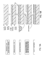
- FIG. 4 shows substantially parallel rows of contacts opened in oxide using pulsed laser ablation in accordance with the present disclosure
- FIG. 5 shows a screenshot with oxide ablation spots for metal contacts
- FIGS. 6A and 6B show the laser-ablated area formed by making ablation spots that are overlapped in both the x and y-direction;
- FIG. 6A shows a 18 micron wide strip opened in 1000 A BSG (boron-doped oxide)/500 A USG (undoped oxide) for base isolation region;
- FIG. 6B shows a 90 micron wide stripe opened in 1000 A USG (undoped oxide) for base region;
- FIG. 7A shows the threshold for oxide damage, below which metal can be removed without metal penetration of the oxide layer
- FIG. 7B shows that after 20 scans the metal runners are fully isolated
- FIG. 7C shows an optical micrograph of the trench formed in this metal stack
- FIGS. 8A and 8B show a top view and a cross-sectional view of a pyramidal TFSC
- FIGS. 9A and 9B show a top view and a cross-sectional view of a prism TFSC
- FIGS. 10A and 10B show a process flow for creation and release of a planar epitaxial thin film silicon solar cell substrate (TFSS);
- TFSS planar epitaxial thin film silicon solar cell substrate
- FIGS. 11A and 11B show a process flow for planar epitaxial thin film silicon solar cell substrate in case the TFSS is too thin to be free standing or self-supporting;
- FIGS. 12A and 12B show a process flow for micromold template (or reusable template) creation for making a 3-D TFSS;
- FIGS. 12C and 12D show a process flow for 3-D TFSS creation using the reusable micromold template
- FIG. 13 shows a process flow for making a planar front contacted solar cell where the TFSS is thick enough to be free standing and self-supporting (e.g. thicker than approximately 50 microns for smaller 100 mm ⁇ 100 mm substrates and thicker than approximately 80 microns for 156 mm ⁇ 156 mm substrates), in accordance with the present disclosure;
- FIG. 14 shows a process flow for making a planar front contact solar cell where the TFSS is too thin to be self supporting, in accordance with the present disclosure
- FIG. 15 shows a process flow for making a 3-D front contact solar cell in accordance with the present disclosure
- FIGS. 16A-16D show a process flow for making an interdigitated back contact back-junction solar cell where the TFSS is thick enough to be self supporting, in accordance with the present disclosure
- FIG. 17 shows a process flow for making an interdigitated back-contact back-junction solar cell using thick TFSS where the in-situ emitter is not deposited. Instead, a BSG (boron-doped oxide) layer is deposited on the epitaxial silicon film and patterned to open the base isolation region, in accordance with the present disclosure;
- BSG boron-doped oxide
- FIG. 18 shows a process flow for making an interdigitated back-contact back-junction solar cell where the TFSS is not thick enough to be self supporting, where in-situ emitter and laser ablation of silicon is used to form the base isolation opening, in accordance with the present disclosure
- FIGS. 19A-19H show a process flow for making an interdigitated back-contact back-junction solar cell where the TFSS is not thick enough to be self supporting, and where instead of in-situ emitter BSG (boron-doped oxide) deposition and selective laser etchback is used to form the base isolation opening, in accordance with the present disclosure;
- BSG boron-doped oxide
- FIG. 20 shows a process flow for making an interdigitated back-contact back-junction solar cell using a 3-D TFSS, in accordance with the present disclosure
- FIG. 21 shows a process flow for making an interdigitated back-contact back-junction hetero-junction solar cell, in accordance with the present disclosure
- FIGS. 22 through 30 are not found in U.S. patent application Ser. No. 13/118,295 “LASER PROCESSING FOR HIGH-EFFICIENCY THIN CRYSTALLINE SILICON SOLAR CELL FABRICATION” by Virendra V. Rana and filed on May 27, 2011;
- FIGS. 22A and 22B are schematics showing the profile of a Gaussian beam and a flat top beam, respectively;
- FIG. 23 is a cross-sectional diagram of a back-contact/back-junction cell
- FIGS. 24A-24F are rear/backside views of a back contact solar cell during fabrication
- FIG. 25 is a rear/backside view of the back contact solar cell of FIG. 24A with alternating metal lines contacting the emitter and base regions;
- FIGS. 26A-26C are diagrams illustrating three ways a flat-top beam profile may be created
- FIGS. 27A and 27B are schematics showing the profile of a Gaussian beam and a flat top beam highlighting the ablation threshold
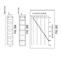
- FIGS. 28A and 28B are diagrams showing a Gaussian beam and a flat top beam ablate region profile/footprint, respectively;
- FIG. 28C is a graph of overlap and scan speed
- FIGS. 29A and 29B are diagrams illustrating a beam alignment window of a Gaussian beam and flat top beam, respectively;
- FIGS. 30A and 30B are diagrams showing a Gaussian beam region profile and a flat top beam region profile, respectively.
- FIG. 30C graphically depicts the results of Table 1.
- the disclosed methods may be useful in the area of semiconductor device ablation, particularly crystalline silicon ablation.
- removal of silicon with a laser involves silicon melting and evaporation that leaves undesirable residual damage in the silicon substrate.
- This damage causes minority carrier lifetime degradation and increased surface recombination velocity (SRV) that reduces the solar cell efficiency.
- SSV surface recombination velocity
- wet cleaning of the silicon substrate is typically used to remove this damage layer.
- the damage remaining in the silicon substrate upon ablating a certain thickness of it using a laser is related to the amount of laser energy absorbed in the substrate that is not used by the ablated material. If it can be managed that most of the laser energy is used in removing the material then the fraction of the incident energy that seeps into the silicon substrate is minimized, thus minimizing the laser-induced substrate damage and SRV degradation.
- the penetration of laser energy into silicon depends on the laser pulse length (also called pulse width) and wavelength.
- the infrared (IR) laser beam, wavelength 1.06 microns has a long penetration depth in silicon, up to about 1000 microns, while green laser beam, with a wavelength of 532 nm, penetrates only to a depth of approximately 3 to 4 microns.
- UV laser beam with a wavelength of 355 nm, is even shorter, only about 10 nm. It is clear that using ultra-short pulses of UV or EUV wavelength limits the penetration of the laser energy into silicon. Additionally, shorter laser pulse length results in shorter diffusion of heat into silicon. While a nanoseconds pulse can lead to heat diffusion in silicon to approximately 3 to 4 microns range, the picoseconds pulse reduces it to about 80 to 100 nm, while a femtoseconds pulse is so short that typically there is no heat diffusion into silicon during the laser ablation process. Hence going to shorter pulses with a shorter wavelength lead to diminishing damage to the laser-ablated substrate. For higher production throughput, green or IR wavelengths can be used depending on the extent of laser damage acceptable.
- FIG. 1 shows a 2.25 micron deep and nearly 100 micron wide trench made in a silicon substrate using a picoseconds UV laser beam of Gaussian profile (M 2 ⁇ 1.3), nearly 110 microns in diameter with 4 microjoule pulse energy, the laser spots overlapped nearly 15 times. This depth of ablation was obtained using twenty overlapped scans of the laser with each scan removing about 112 nm of silicon.
- FIG. 1 shows a 2.25 micron deep and nearly 100 micron wide trench made in a silicon substrate using a picoseconds UV laser beam of Gaussian profile (M 2 ⁇ 1.3), nearly 110 microns in diameter with 4 microjoule pulse energy, the laser spots overlapped nearly 15 times. This depth of ablation was obtained using twenty overlapped scans of the laser with each scan removing about 112 nm of silicon.
- FIG. 2 shows the smooth profile of a 4 micron deep and 110 micron wide trench in silicon obtained using the same picoseconds laser beam with the UV wavelength.
- the smoothness of the profile should be noted.
- Such an ablation of silicon is used in all back-contact back-junction solar cells to form regions that isolate base regions from emitter regions.
- Use of a femtoseconds laser may provide further reduction of laser damage during silicon ablation.
- the embodiments of this disclosure are also applicable to the ablation of amorphous silicon.
- a similar scheme may be used to ablate a desired thickness of amorphous silicon using a pulsed laser beam with femtoseconds pulse length and in some embodiments a UV or green wavelength. Since ablation of amorphous silicon requires much lower energy than crystalline silicon, such a scheme may effectively be used to selectively ablate amorphous silicon films from the crystalline silicon surface for application to hetero-junction solar cells.
- This disclosure is also applicable to oxide ablation selective to the underlying substrate, crystalline or amorphous silicon.
- the oxide film is transparent to laser beams of wavelength down to UV. If a nanoseconds pulse length laser is used to remove the overlying oxide, the removal of oxide takes place by heating and melting of silicon underneath. Because of the pressure from the ablated silicon underneath, the overlying oxide is cracked and removed. This however, creates heavy damage in the silicon substrate so that a wet cleaning treatment is typically used to remove this damaged layer for use in high efficiency cells.
- FIGS. 3A-3D disclose the procedure for obtaining reduced damage ablation of oxide.
- FIG. 3A shows the variation of laser spot opening in a 1000 A PSG (phosphorus-doped oxide)/500 A USG (undoped oxide) stack on a 35 micron thick epitaxial silicon film on a template, using a picoseconds UV laser beam.
- the oxide layers were deposited using APCVD (atmospheric-pressure CVD) technique.
- APCVD atmospheric-pressure CVD
- the spot size depends on the laser fluence (J/cm 2 ).
- the laser fluence is the laser pulse energy divided by the area of the laser beam. In this case, the laser beam was about 100 microns in diameter with a Gaussian profile (M 2 ⁇ 1.3).
- FIG. 4 shows rows of cell contact openings that are selectively opened in the oxide for application in all back-contact (and back-junction) solar cells.
- FIG. 5 is a close-up of these contacts.
- the laser ablation spots can be overlapped in both x and y direction to open up an area of any desired length and width on the wafer as shown in FIGS. 6A and 6B .
- FIG. 6A shows a 180 micron wide opening made by selectively removing the BSG (boron-doped oxide) for base isolation region using picoseconds UV laser beam with ablation spots overlapping in both x and y-direction.
- FIG. 6B shows a 90 micron wide area opened up in USG (undoped oxide) for forming the base region.
- the selective ablation of oxide from a silicon surface as disclosed here can be used in solar cell making in several ways.
- this process is used to open tracks in an oxide film to expose the underlying emitter.
- the emitter so exposed may be removed using wet etching.
- This region is then used for base to emitter isolation and with base formed inside it.
- this process is used to open regions that are then used for making metal contacts.
- the oxide passivation can be used on the backside of the cells.
- the scheme described here is then used to open contacts for the metal that is subsequently deposited on these contacts. In this manner, the metal has localized contact that is conducive to high cell efficiency.
- contacts for both base and emitter may be opened using this scheme.
- a doped oxide may need to be removed without causing any doping of the silicon underneath (i.e., without any appreciable heating of the doped oxide and silicon structure). Since, as described above, the oxide is removed by separation at the oxide/silicon substrate interface when using a picoseconds laser beam, the removal of oxide happens with limited pickup of the dopant from the oxide film being ablated.
- SiN x silicon nitride
- the selective ablation of silicon nitride (SiN x ) is used for front contacted solar cells. Using laser ablation, the contact area to the emitter surface can be reduced thereby minimizing the area where the SiN passivation is removed. This leads to higher V OC .
- Picosecond lasers with either UV or green wavelength are suitable for this application, although nanoseconds UV lasers can also be used.
- LFC laser fired contacts
- metal is the first metal in contact with base and emitter (aluminum being used as the contact and light trapping rear mirror layer).
- a laser with picoseconds pulse length is suitable for this application.
- the IR wavelength is quite suitable.
- metal is ablated at a pulse energy that is lower than the threshold for oxide ablation. If the thickness of metal removed in one scan is lower than the desired thickness, multiple overlapping scans are used to remove the full thickness of metal. Since the pulse energy is below the oxide ablation threshold, a clean removal of metal from the oxide surface is obtained.
- the exact recipe used highly depends on the type of metal in the stack, their thickness and surface roughness, etc.
- FIGS. 7A-7C shows the ablation results when patterning a PVD-deposited bi-layer stack of 2400 A of NiV on 1200 A of Al on oxide. It is desired that the metal be removed completely between the runners without breaking through the oxide layer underneath (to prevent shunts in the cell).
- FIG. 7A shows the threshold for pulse energy, below which this metal stack can be removed without penetration of oxide. This threshold, besides depending on the metal stack characteristics described above, depends on the laser parameters such as spot overlap obtained using a certain pulse repetition rate of the laser as well as the scan speed. With increasing pulse overlap the threshold pulse energy would decrease, because of the energy accumulation in the metal.
- FIG. 7A shows the ablation results when patterning a PVD-deposited bi-layer stack of 2400 A of NiV on 1200 A of Al on oxide. It is desired that the metal be removed completely between the runners without breaking through the oxide layer underneath (to prevent shunts in the cell).
- FIG. 7A shows the threshold for pulse energy, below which this metal stack can be removed without penetration of oxide.
- FIG. 7B shows that using a pulse energy below the threshold for oxide damage, more than twenty scans provided complete isolation of metal runners as determined by the 100M-ohm resistance between parallel lines.
- FIG. 7C shows a clean 75 micron trench formed in the 2400 A NiV/1200 Al metal stack.
- the third scheme of metal ablation is applicable to highly reflective films, for example Al/Ag stack (with Al in contact with the cell and Ag on top of Al), such that most of the incident energy of the picoseconds laser is reflected and ablation is drastically reduced.
- the surface of the reflective metal (Ag) is first dented using a long pulse length nanoseconds laser, pulse length from 10 to 800 nanoseconds, followed by picoseconds cleanup of the aluminum underneath.
- This disclosure is also applicable to the selective doping of a substrate.
- the pulse energy should be high enough to melt the silicon but not high enough to ablate it or the dopant layer above it. As the silicon melts, the dopant is dissolved into it. Upon recrystallization of this silicon layer, a doped layer is obtained.
- a nanoseconds pulse length laser with green wavelength is quite suitable because of its limited penetration into silicon.
- the laser processing techniques described above are applicable to planar and 3-D thin-film crystalline silicon substrates.
- the laser processes described here are suitable for any thickness of the silicon substrate. These include the current standard wafer thickness of ⁇ 150 microns used for crystalline silicon solar cells. However, they become even more advantageous for thin, fragile wafers or substrates as the process in carried out without any contact with the substrate.
- These include the wafers thinner than 150 micron obtained from monocrystalline CZ ingots or multi-crystalline bricks using advanced wire sawing techniques or by other techniques such as hydrogen implantation followed by annealing to separate the desired thickness of wafer, or thin-film monocrystalline substrates (such as in the thickness range of from a few microns up to 80 microns) obtained using epitaxial deposition of silicon on a sacrificial separation/release layer such as porous silicon and its subsequent lift off.
- FIGS. 8A through 9B show the 3-D thin film silicon substrates obtained using the technique described in that publication.
- FIG. 8A shows the top view while FIG. 8B shows the cross-section of the TFSS so obtained.
- the tips may be flat or may end in a sharp point.
- FIGS. 9A and 9B show the TFSS with prism structure obtained using a reusable pre-structured 3D template described in the reference above.
- the laser processes and the process flows described here are applicable to any thickness of the silicon substrate (from less than one micron to over 100 microns), we disclose here their application to solar cells made using thin silicon substrates in the thickness range of from less than 1 micron to about 80 microns, including but not limited to those that are obtained using epitaxial silicon on porous silicon surface of a reusable template as described in the '713 application.
- a desired thickness e.g. from about less than 10 microns up to about 120 microns
- FIGS. 12A-12D show the process flow for obtaining three-dimensional pyramidal silicon substrates. Three-dimensional prism-shaped substrates can be obtained with similar processes, but using a lithography or screen printed pattern that provides for that structure.
- the thin planar substrate obtained using the process flow of FIGS. 10A and 10B may be processed according to the process flow of FIG. 13 to obtain high efficiency front contacted solar cells.
- the laser processes of selective ablation of silicon oxide and silicon nitride (SiN) are used to advantage in making this front contacted solar cell.
- FIG. 14 shows the application of various laser processes for making high efficiency front contacted solar cells using planar TFSSs where the TFSS is too thin to be free standing or self supporting during cell processing. It should be noted that in this case the non-template side surface is processed first with the TFSS on the template. Once this processing is complete the TFSS is first attached to a reinforcement plate or sheet (also called a backplane) on the exposed processed side and then separated from the template.
- a reinforcement plate or sheet also called a backplane
- FIG. 15 shows the application of various laser processes for making high efficiency front contacted solar cells using 3-D front TFSS.
- pyramid tips on the template side not be sharp but end in flat ledges.
- FIGS. 16A-16D show the laser processes used on the planar epitaxial substrate to make a back-contact/back-junction solar cell where the TFSS is self supporting (i.e., no backplane attachment to the cell).
- the epitaxial emitter is deposited in-situ during silicon epitaxy following the deposition of the epitaxial silicon base.
- the ablation of silicon is then used to remove the emitter from the base isolation regions.
- four fiducials are etched into oxide to align subsequent ablation to this pattern.
- a thermal oxide is grown to passivate the silicon surface that will become the back surface of the back-contact back-junction solar cell.
- the epitaxial silicon film is then disconnected or released from the template (by mechanical release from the porous silicon interface).
- the residual porous silicon layer is wet etched and the surface is textured (both can be done using an alkaline etch process). This will become the textured front surface or the sunnyside of the solar cell.
- the thermal oxide is ablated using a picoseconds UV laser to form base openings inside the base isolation region.
- the base opening is aligned inside the base isolation region (trench) formed by silicon ablation earlier using the fiducials that were etched in silicon earlier as mentioned above.
- a phosphorous containing oxide layer (PSG) is blanket deposited on the surface. Scanning with a nanosecond green or IR laser aligned to base opening using the fiducials in silicon causes the base to be doped.
- the region that will have the contact openings to emitter is also doped in a similar manner using the aligned scans of nanosecond green or IR laser.
- contact opening are made to these doped base and emitter areas using a picoseconds UV laser.
- the alignment of these contact openings is made using fiducials in silicon.
- a metal stack layer comprising aluminum as its first layer in contact with the cell (e.g., a stack of 1250 A Al/100-250 A NiV/2250 Sn) is deposited using a suitable method such as a PVD (physical vapor deposition) technique.
- this layer is patterned using a picoseconds IR laser so that the metal runners are separately connected to the base and emitter regions.
- FIG. 17 shows the laser processes used on the planar epitaxial substrate to make a back-contact solar cell where epitaxial silicon base is not deposited with an emitter layer. Instead, a boron containing oxide (BSG) layer is deposited and patterned to open the base isolation region.
- BSG boron containing oxide
- FIG. 18 shows a process flow using laser processes on the epitaxial substrate to make a planar back-contact/back-junction solar cell where the TFSS is not self-supporting (hence, a backplane is used).
- This flow uses the silicon ablation of in-situ doped emitter to form the base isolation region.
- FIG. 19A-19H show a process flow using laser processes on the epitaxial substrate to make a planar back contact solar cell where the TFSS is not self-supporting.
- the BSG deposition and selective laser ablation followed by thermal oxidation is used to form the emitter as well as the base isolation region.
- FIG. 20 shows a process flow for making back contacted 3-D solar cells, it is advantageous to have the template side of pyramids end in relatively sharp points. Since the 3-D TFSS can be self-supporting to relatively low thickness (e.g., silicon as thin as about 25 microns), the process flow is similar to that shown in FIG. 16 . It should be clear that we again have a choice of using the in-situ emitter followed by laser ablation of silicon, or BSG deposition and selective laser ablation followed by thermal oxidation (or thermal anneal, or thermal oxidizing anneal).
- a hetero-junction emitter may be formed by a doped amorphous silicon layer in contact with an oppositely doped crystalline silicon base.
- TCO transparent conducting oxide
- Femtoseconds pulsewidth lasers with either UV or green wavelength are suitable for this application.
- a process flow is described in FIG. 21 . Several variations of this process flow are possible.
- Various embodiments and methods of this disclosure include at least the following aspects: the process to obtain ablation of crystalline and amorphous silicon with reduced damage; the process to obtain oxide ablation for both doped and undoped oxides with reduced damage to silicon; the process to obtain fully isolated metal patterns on a dielectric surface for solar cell metallization; the process to selectively dope the emitter and base contact regions; the use of pulsed laser processing on very thin wafers, including planar and 3-D silicon substrate; the use of pulsed laser processing on substrates obtained using epitaxial deposition on a reusable template made using template pre-structuring techniques; the use of various pulsed laser processes in making front contacted homo-junction solar cells; the use of various pulsed laser processes in making all-back contacted homo-junction solar cells; and the use of various pulsed laser processes in making hetero-junction solar cells.
- n-type for front contact solar cell with P + emitter and p-type base for back-contact back-junction solar cells with p-type base and n + emitter.
- FIGS. 22 through 30 are not found in U.S. patent application Ser. No. 13/118,295 “LASER PROCESSING FOR HIGH-EFFICIENCY THIN CRYSTALLINE SILICON SOLAR CELL FABRICATION” by Virendra V. Rana and filed on May 27, 2011.
- the description following is directed towards methods for the formation of back contact solar cells utilizing flat top laser beams as compared to traditional Gaussian laser beams.
- the implementation of flat top laser beams to the laser processing methods described throughout this application provides substantial reduction in damage to silicon, improvement in solar cell fabrication throughput, and a bigger alignment window for defining patterns (e.g. patterns of emitter and base regions) that are inset inside another pattern.
- FIGS. 22A and 22B are schematics showing the profile of a Gaussian beam, FIG. 22A , and a flat top beam, FIG. 22B .
- the beam intensity of the Gaussian beam has a smooth decrease from a maximum at the beam center to the outside of the beam. In contrast, the intensity is “flat” or uniform for the flat top beam through most of its profile (center to outside).
- high-efficiency back-contacted, back-junction cells with interdigitated back contact (IBC) metallization benefits from the use of at least one or several steps of pulsed laser processing.
- Laser processing may be utilized in several processing steps throughout the formation of the back contact cell, including: delineating/defining emitter and base regions (or base-to-emitter isolation region), defining back-surface field (BSF) or base regions, doping to form back surface fields (by laser irradiation), selective doping of contacts, opening contacts in the dielectric to base and emitter, and metal patterning.
- Some of these steps require laser processing of wide areas that are typically produced by overlapping Gaussian beam laser spots. Overlapping severely reduces cell processing speed and may cause silicon damage, resulting in degradation of cell performance and yield.
- the overlapping of spots is dramatically reduced so that the semiconductor (e.g., crystalline silicon) substrate damage is significantly reduced and throughput is increased.
- smaller diameter Gaussian spots may be replaced with a relatively wide flat top laser beam which may further substantially increase the throughput.
- FIGS. 23-25 illustrate embodiments of back contact solar cells that may be formed according to the disclosed flat top laser beam processing methods.
- FIG. 23 is a cross-sectional diagram of a back-contact/back-junction cell with interdigitated back-contact (IBC) metallization formed from an n-type substrate, such as that disclosed herein.
- IBC interdigitated back-contact
- alternating emitter and base regions are separated by relatively lightly n-doped substrate regions (the n-type base).
- the rear/backside surface is covered by a surface passivation layer that provides good surface passivation with low back surface recombination velocity, made of, for example: thermal silicon dioxide, deposited silicon dioxide, or silicon oxide/silicon nitride layers which may be deposited using techniques such as PECVD or APCVD (and/or aluminum oxide deposited by atomic layer deposition or ALD).
- This surface passivation process may then be followed by making openings in this passivation layer which act as ‘localized contacts’ to the emitter and base regions. Then conductor deposition and patterning (e.g., aluminum as shown in FIG. 23 ) may be performed to separately connect the emitter and base regions.
- conductor deposition and patterning e.g., aluminum as shown in FIG. 23
- FIG. 24A is a rear/backside view of a back contact solar cell illustrating an interdigitated back contact base and emitter design with the emitter and base regions laid out in alternating parallel rows.
- This backside may be formed, for example, by starting with a surface that is completely covered by an emitter region, then delineating a base region resulting in the formation of the patterned emitter regions. Then doping base contact regions with phosphorous is carried out and contacts are opened to the base and emitter regions in preparation for metallization.
- FIGS. 24B-24F are rear/backside views of a back contact solar cell illustrating the back contact cell after key processing steps, wherein any one step or combination of steps may be performed according to a laser process which may or may not utilize a flat top beam.
- the various laser patterning steps of this particular exemplary method are outlined in FIGS. 24B-24E .
- a BSG layer is deposited over the whole surface.
- the emitter to BSF isolation region is defined using laser ablation of the BSG as shown in FIG. 24B .
- This step, the delineation of base and emitter regions, is referred to herein as the “BSG Opening” step.
- an in-situ boron doped layer may be deposited during silicon epitaxy and the BSF region defined using laser ablation of silicon.
- a USG layer is deposited on the wafer followed by laser ablation of this layer in patterns that are inlaid to the BSG Open region, as shown in FIG. 24C .
- This patterning step is referred to herein as the BSF Opening step or base opening step.
- the BSF openings should be isolated from the edges of the BSG Openings to prevent shunt formation as shunts are deleterious to the solar cell efficiency.
- a PSG layer is deposited on the wafer and the silicon exposed to PSG in the BSF opening is doped using selective laser scans of this area.
- the doped BSF regions base regions are outlined in FIG. 24D
- the contacts to base and emitter are made using laser ablation as shown in FIG. 24E .
- the contacts may be point contacts as shown in FIG. 24E or line contacts as shown in FIG. 24F .
- the number of contacts or the number of lines should be optimized for minimum series resistance of the current conduction path for the solar cell—thus the designs and methods of the disclosed subject matter are not limited to the exemplary embodiments shown herein. It is also important that the contact openings are properly aligned inside the particular doped area so that there is no current leakage.
- a picoseconds pulse length laser may be used for oxide ablation processes of BSG open, BSF opening, and contact opening, although a nanoseconds pulse length laser may also be used.
- IR wavelength may be used, green or UV or smaller wavelengths are more suitable because of their reduced penetration into silicon.
- a nanoseconds pulse length laser may be more suitable because of its penetration into silicon.
- IR wavelength may be used, green wavelength, because of its reduced penetration compared to IR, may be more suitable for the depth of doping typically desired.
- FIG. 25 is a rear/backside view of the back contact solar cell of FIG. 24A with alternating metal lines contacting the emitter and base regions. Note that the metal lines for the emitter and base regions are separately connected to busbars not shown in FIG. 25 for simplicity of the figure.
- This metal pattern may be formed by blanket deposition of a metal followed by laser ablation of the metal to isolate base contacts from emitter contacts. Because relatively thick metal lines are required for good current conduction (usually lines 20 ⁇ m thick or thicker), a thinner metal stack such as aluminum/nickel-vanadium/Tin may be first deposited and patterned by lasers, followed by the selective deposition of a thicker metal such as copper using electro or electroless plating. Alternatively, a backplane with relatively thick conductors may be applied and attached to the cell with thin conductor lines. A picoseconds pulse length laser with IR wavelength may be most suitable for ablating the metal stack with good selectivity to the underlying oxide layer.
- the disclosed flat top laser beam processing steps that may be utilized to make this structure possible include, but are not limited to: delineation of emitter and base regions (BSF and emitter to BSF isolation) by laser ablation of an emitter or deposited boron doping dielectric (such as boro-silicate glass BSG deposited by APCVD); delineation of the BSF region by opening the dielectric covering the opening made in the BSG; N+ doping of the base (e.g., with phosphorus); opening of metallization contacts to base and emitter regions; and metal patterning using metal laser ablation to isolate base and emitter contacts.
- FIGS. 26A-26C are diagrams illustrating three ways a flat-top beam profile may be created (diagrams reproduced from F. M.
- FIG. 26A illustrates one technique for creating a flat top beam profile, the so-called “aperturing of the beam.” Using this method, the Gaussian beam is made flatter by expanding it and an aperture is used to select a reasonable flat portion of the beam and to cut-out the gradually decreasing ‘sidewall’ areas of the beam. Using this method, however, may cause a significant loss of beam power.
- a second example method for creating a flat top beam uses beam integration wherein multiple-aperture optical elements, such as a micro-lens array, break the beam into many smaller beams and recombine them at a fixed plane.
- This beam integration method may work very well with beams of high M 2 value.
- a third beam shaping system for creating a flat top beam uses a diffractive grating or a refractive lens to redistribute the energy and map it to the output plane.
- Any known method including the three example techniques disclosed in FIGS. 26A-26C , may be used obtain the flat top beam profile for applications described herein.
- the suitability and choice of a flat top laser beam formation method depends on a variety of factors including the available beam characteristics and the results desired.
- FIGS. 27A and 27B are schematics showing the profile of a Gaussian beam and a flat top beam highlighting the ablation threshold.
- a flat top laser beam particularly as compared to a Gaussian beam, can substantially reduce the laser damage during ablation and doping processing.
- the flat top beam can be configured so the peak intensity is only slightly above that required to ablate the material (the ablation threshold as shown in FIG. 27B ) and the damage that may be caused by the high intensity of the Gaussian beam is avoided.
- FIG. 28A is diagram showing a Gaussian beam ablated region profile/footprint.
- the circular shaped spots of a Gaussian beam are required to overlap substantially to minimize the zigzag outline of the pattern, typically as much as 50% overlap ( FIG. 28A ).
- FIG. 28B is diagram showing a flat top beam ablate region profile/footprint. Since the square or rectangular flat top beam have flat edges, thus creating a flat outline, the overlap can be significantly reduced ( FIG. 28B ).
- FIG. 28C is a graph showing the improvement in scan speed as beam overlap is reduced. Note that even for an overlap of 30%, a scan speed increase of 33% may be realized.
- FIG. 29A is a diagram illustrating a beam alignment window of a Gaussian beam
- FIG. 29B is a diagram illustrating a beam alignment window of a flat top beam.
- FIGS. 29A and 29B yet another advantage of using a flat top beam for making inlaid patterns is the larger alignment window the flap top beam provides.
- the circular shaped spots obtained from a Gaussian beam create zigzag edges of the ablated regions ( FIG. 29A ).
- the alignment margin of M as shown in FIG. 29A is reduced and limited to M-a-b due to the waviness of the zigzag edge profile.
- the ablation region edges created using a flat top beam are straight allowing the alignment margin to stay at M.
- BSF openings are formed inside the BSG Open regions, and contact openings are formed inside the BSF region.
- a larger alignment margin is important as it allows for smaller BGS Open, BSF, and contact regions.
- Table 1 shows the reduction in the number of scans needed to open a 150 ⁇ m wide line, such as used for delineating the base area by ablating the BSG film.
- Table 1 below shows the throughput of Gaussian vs. Flat Top laser beams for creating a 90 ⁇ m wide base opening. The results of Table 1 are shown graphically in FIG. 30C .
- FIG. 30C shows the throughput advantage of flat top beams (the 60 ⁇ m flat top beam region profile is depicted in FIG. 30B ) as compared to the Gaussian beam (the 30 ⁇ m flat top beam region profile is depicted in FIG. 30A ), for a high productivity laser system that can process four wafers at a time.
- two lasers may be utilized with each laser beam further split into two.
- this flat top laser beam hardware and fabrication scheme are possible.
- Similar throughput advantages may also result when utilizing a flat top beam for opening the oxide region for BSF, doping the BSF region using the overlying PSG, forming base and metal contact openings if they are line contacts, and the metal ablation isolation lines—all with the concurrent advantage of reduced silicon damage. Additionally, utilizing a flat top beam provides the advantage of increased alignment window for BSF opening inside the BSG opening and contact opening inside the BSF.
- Flat top laser processing methods may also increase throughput for forming a back surface field.
- the back surface field may be formed by doping the base region, opened as described, with an n-type dopant such as phosphorous.
- the base is covered with a phosphorus-doped silicon oxide (PSG) layer and the doping may be performed by irradiating this region with a laser beam. While uniformly doping this region using Gaussian laser beams requires overlapping, overlapping is minimized or may be completely reduced using a flat top beam. And as with the base and emitter region delineation and back surface field delineation described herein, utilizing a flat top laser beam provides a substantial throughput and reduced damage advantage as required overlapping is decreased. It should be noted that for forming a back surface field, the beam need to be flat top beam only in one direction—normal to the scan, whereas it may be Gaussian in the direction of the scan. This type of beam is called a hybrid flat top beam.
- PSG phosphorus-doped silicon oxide
Abstract
Description
| TABLE 1 | |||||
| Width | Spot | Pitch of | Number | ||
| of line | Size | scans | of scans | ||
| PROCESS | (um) | (um) | Overlap % | (um) | per line |
| BSG Ablation with | 150 | 30 | 50 | 15 | 9 |
| Gaussian | |||||
| BSG Ablation with Flat | 150 | 30 | 20 | 24 | 6 |
| Top | |||||
| BSG Ablation with Flat | 150 | 60 | 20 | 48 | 3 |
| Top | |||||
Claims (20)
Priority Applications (13)
| Application Number | Priority Date | Filing Date | Title |
|---|---|---|---|
| US13/271,212 US9508886B2 (en) | 2007-10-06 | 2011-10-11 | Method for making a crystalline silicon solar cell substrate utilizing flat top laser beam |
| US13/303,488 US20130164883A1 (en) | 2007-10-06 | 2011-11-23 | Laser annealing applications in high-efficiency solar cells |
| US13/340,887 US20120225515A1 (en) | 2004-11-30 | 2011-12-30 | Laser doping techniques for high-efficiency crystalline semiconductor solar cells |
| KR1020137020198A KR101384853B1 (en) | 2010-12-30 | 2011-12-30 | Laser processing methods for photovoltaic solar cells |
| US13/340,877 US8637340B2 (en) | 2004-11-30 | 2011-12-30 | Patterning of silicon oxide layers using pulsed laser ablation |
| PCT/US2011/068037 WO2012092537A2 (en) | 2010-12-30 | 2011-12-30 | Laser processing methods for photovoltaic solar cells |
| EP11853473.4A EP2659518A4 (en) | 2010-12-30 | 2011-12-30 | Laser processing methods for photovoltaic solar cells |
| US13/340,903 US9455362B2 (en) | 2007-10-06 | 2011-12-30 | Laser irradiation aluminum doping for monocrystalline silicon substrates |
| US13/852,966 US20130288425A1 (en) | 2011-08-05 | 2013-03-28 | End point detection for back contact solar cell laser via drilling |
| US14/137,172 US9236510B2 (en) | 2004-11-30 | 2013-12-20 | Patterning of silicon oxide layers using pulsed laser ablation |
| US14/991,789 US20170005206A1 (en) | 2007-10-06 | 2016-01-08 | Patterning of silicon oxide layers using pulsed laser ablation |
| US15/276,740 US20170236969A1 (en) | 2007-10-06 | 2016-09-26 | Laser irradiation aluminum doping for monocrystalline silicon substrates |
| US15/361,832 US20170236961A1 (en) | 2007-10-06 | 2016-11-28 | Flat top laser beam processing for making a solar cell substrate |
Applications Claiming Priority (7)
| Application Number | Priority Date | Filing Date | Title |
|---|---|---|---|
| US11/868,492 US20090107545A1 (en) | 2006-10-09 | 2007-10-06 | Template for pyramidal three-dimensional thin-film solar cell manufacturing and methods of use |
| US11/868,488 US8129822B2 (en) | 2006-10-09 | 2007-10-06 | Template for three-dimensional thin-film solar cell manufacturing and methods of use |
| US12/774,713 US8420435B2 (en) | 2009-05-05 | 2010-05-05 | Ion implantation fabrication process for thin-film crystalline silicon solar cells |
| US39186310P | 2010-10-11 | 2010-10-11 | |
| US13/118,295 US8399331B2 (en) | 2007-10-06 | 2011-05-27 | Laser processing for high-efficiency thin crystalline silicon solar cell fabrication |
| US13/271,212 US9508886B2 (en) | 2007-10-06 | 2011-10-11 | Method for making a crystalline silicon solar cell substrate utilizing flat top laser beam |
| US201213057104A | 2012-08-13 | 2012-08-13 |
Related Parent Applications (2)
| Application Number | Title | Priority Date | Filing Date |
|---|---|---|---|
| US11/868,488 Continuation-In-Part US8129822B2 (en) | 2004-11-30 | 2007-10-06 | Template for three-dimensional thin-film solar cell manufacturing and methods of use |
| US201413807631A Continuation-In-Part | 2011-08-05 | 2014-09-11 |
Related Child Applications (4)
| Application Number | Title | Priority Date | Filing Date |
|---|---|---|---|
| US13/118,295 Continuation-In-Part US8399331B2 (en) | 2004-11-30 | 2011-05-27 | Laser processing for high-efficiency thin crystalline silicon solar cell fabrication |
| US13/188,295 Continuation-In-Part US8892112B2 (en) | 2007-10-06 | 2011-07-21 | Selection of a radio access bearer resource based on radio access bearer resource historical information |
| US13/204,626 Continuation-In-Part US8946547B2 (en) | 2010-08-05 | 2011-08-05 | Backplane reinforcement and interconnects for solar cells |
| US15/361,832 Continuation US20170236961A1 (en) | 2007-10-06 | 2016-11-28 | Flat top laser beam processing for making a solar cell substrate |
Publications (2)
| Publication Number | Publication Date |
|---|---|
| US20120122272A1 US20120122272A1 (en) | 2012-05-17 |
| US9508886B2 true US9508886B2 (en) | 2016-11-29 |
Family
ID=46050439
Family Applications (2)
| Application Number | Title | Priority Date | Filing Date |
|---|---|---|---|
| US13/271,212 Expired - Fee Related US9508886B2 (en) | 2004-11-30 | 2011-10-11 | Method for making a crystalline silicon solar cell substrate utilizing flat top laser beam |
| US15/361,832 Abandoned US20170236961A1 (en) | 2007-10-06 | 2016-11-28 | Flat top laser beam processing for making a solar cell substrate |
Family Applications After (1)
| Application Number | Title | Priority Date | Filing Date |
|---|---|---|---|
| US15/361,832 Abandoned US20170236961A1 (en) | 2007-10-06 | 2016-11-28 | Flat top laser beam processing for making a solar cell substrate |
Country Status (1)
| Country | Link |
|---|---|
| US (2) | US9508886B2 (en) |
Families Citing this family (33)
| Publication number | Priority date | Publication date | Assignee | Title |
|---|---|---|---|---|
| US8399331B2 (en) | 2007-10-06 | 2013-03-19 | Solexel | Laser processing for high-efficiency thin crystalline silicon solar cell fabrication |
| US8637340B2 (en) | 2004-11-30 | 2014-01-28 | Solexel, Inc. | Patterning of silicon oxide layers using pulsed laser ablation |
| US8193076B2 (en) | 2006-10-09 | 2012-06-05 | Solexel, Inc. | Method for releasing a thin semiconductor substrate from a reusable template |
| US9455362B2 (en) | 2007-10-06 | 2016-09-27 | Solexel, Inc. | Laser irradiation aluminum doping for monocrystalline silicon substrates |
| EP2356675B1 (en) | 2008-11-13 | 2016-06-01 | Solexel, Inc. | Three dimensional thin film solar cell and manufacturing method thereof |
| US8906218B2 (en) | 2010-05-05 | 2014-12-09 | Solexel, Inc. | Apparatus and methods for uniformly forming porous semiconductor on a substrate |
| US9076642B2 (en) | 2009-01-15 | 2015-07-07 | Solexel, Inc. | High-Throughput batch porous silicon manufacturing equipment design and processing methods |
| US9318644B2 (en) | 2009-05-05 | 2016-04-19 | Solexel, Inc. | Ion implantation and annealing for thin film crystalline solar cells |
| CN102844883B (en) | 2010-02-12 | 2016-01-20 | 速力斯公司 | For the manufacture of the two-sided reusable template of the Semiconductor substrate of photocell and microelectronic component |
| US8263899B2 (en) * | 2010-07-01 | 2012-09-11 | Sunpower Corporation | High throughput solar cell ablation system |
| US9748414B2 (en) | 2011-05-20 | 2017-08-29 | Arthur R. Zingher | Self-activated front surface bias for a solar cell |
| WO2013101846A1 (en) * | 2011-12-26 | 2013-07-04 | Solexel, Inc. | Systems and methods for enhanced light trapping in solar cells |
| US9054255B2 (en) | 2012-03-23 | 2015-06-09 | Sunpower Corporation | Solar cell having an emitter region with wide bandgap semiconductor material |
| WO2013181298A1 (en) * | 2012-05-29 | 2013-12-05 | Solexel, Inc. | Structures and methods of formation of contiguous and non-contiguous base regions for high efficiency back-contact solar cells |
| DE102012211161A1 (en) * | 2012-06-28 | 2014-02-06 | Robert Bosch Gmbh | Method for forming an electrically conductive structure on a carrier element, layer arrangement and use of a method or a layer arrangement |
| KR101828423B1 (en) | 2012-08-08 | 2018-03-29 | 엘지전자 주식회사 | Solar cell |
| CN103165697B (en) * | 2013-04-01 | 2015-09-02 | 南通大学 | The manufacturing process of homotype heterojunction solar battery |
| US9214585B2 (en) * | 2013-04-29 | 2015-12-15 | Solexel, Inc. | Annealing for damage free laser processing for high efficiency solar cells |
| WO2015130989A1 (en) * | 2014-02-26 | 2015-09-03 | Solexel, Inc. | Self aligned contacts for back contact solar cells |
| US9716192B2 (en) | 2014-03-28 | 2017-07-25 | International Business Machines Corporation | Method for fabricating a photovoltaic device by uniform plating on emitter-lined through-wafer vias and interconnects |
| US20150325716A1 (en) * | 2014-05-08 | 2015-11-12 | International Business Machines Corporation | Manufacture and structure for photovoltaics including metal-rich silicide |
| US9537041B2 (en) | 2014-06-27 | 2017-01-03 | Sunpower Corporation | Emitters of a backside contact solar cell |
| JP2017037899A (en) * | 2015-08-07 | 2017-02-16 | シャープ株式会社 | Solar battery cell |
| WO2017068959A1 (en) * | 2015-10-21 | 2017-04-27 | シャープ株式会社 | Back-contact electrode type solar battery cell and manufacturing method for back-contact electrode type solar battery cell |
| JP2017143267A (en) * | 2016-02-12 | 2017-08-17 | エルジー エレクトロニクス インコーポレイティド | Solar cell and method of manufacturing the same |
| CN107482079A (en) * | 2016-06-02 | 2017-12-15 | 上海神舟新能源发展有限公司 | Selective emitter junction and tunnel oxide high-efficiency N-type battery preparation method |
| MY190562A (en) * | 2016-12-20 | 2022-04-27 | Zhejiang Kaiying New Mat Co Ltd | Interdigitated back contact metal-insulator-semiconductor solar cell with printed oxide tunnel junctions |
| MY189222A (en) | 2016-12-20 | 2022-01-31 | Zhejiang Kaiying New Mat Co Ltd | Siloxane-containing solar cell metallization pastes |
| US10854646B2 (en) * | 2018-10-19 | 2020-12-01 | Attollo Engineering, LLC | PIN photodetector |
| US10622502B1 (en) | 2019-05-23 | 2020-04-14 | Zhejiang Kaiying New Materials Co., Ltd. | Solar cell edge interconnects |
| US10749045B1 (en) | 2019-05-23 | 2020-08-18 | Zhejiang Kaiying New Materials Co., Ltd. | Solar cell side surface interconnects |
| CN110993704A (en) * | 2019-12-20 | 2020-04-10 | 浙江爱旭太阳能科技有限公司 | Method for producing a solar cell and solar cell |
| CN111180530A (en) * | 2019-12-27 | 2020-05-19 | 天津爱旭太阳能科技有限公司 | Preparation method of selective emitter battery |
Citations (205)
| Publication number | Priority date | Publication date | Assignee | Title |
|---|---|---|---|---|
| US4043894A (en) | 1976-05-20 | 1977-08-23 | Burroughs Corporation | Electrochemical anodization fixture for semiconductor wafers |
| US4070206A (en) | 1976-05-20 | 1978-01-24 | Rca Corporation | Polycrystalline or amorphous semiconductor photovoltaic device having improved collection efficiency |
| US4082570A (en) | 1976-02-09 | 1978-04-04 | Semicon, Inc. | High intensity solar energy converter |
| US4165252A (en) | 1976-08-30 | 1979-08-21 | Burroughs Corporation | Method for chemically treating a single side of a workpiece |
| US4249959A (en) | 1979-11-28 | 1981-02-10 | Rca Corporation | Solar cell construction |
| US4251679A (en) | 1979-03-16 | 1981-02-17 | E-Cel Corporation | Electromagnetic radiation transducer |
| US4348254A (en) | 1978-12-27 | 1982-09-07 | Solarex Corporation | Method of making solar cell |
| US4361950A (en) | 1980-03-24 | 1982-12-07 | Exxon Research & Engineering Co. | Method of making solar cell with wrap-around electrode |
| US4409423A (en) | 1982-03-09 | 1983-10-11 | The United States Of America As Represented By The Secretary Of The Air Force | Hole matrix vertical junction solar cell |
| US4427839A (en) | 1981-11-09 | 1984-01-24 | General Electric Company | Faceted low absorptance solar cell |
| US4430519A (en) | 1982-05-28 | 1984-02-07 | Amp Incorporated | Electron beam welded photovoltaic cell interconnections |
| US4461922A (en) | 1983-02-14 | 1984-07-24 | Atlantic Richfield Company | Solar cell module |
| US4479847A (en) | 1981-12-30 | 1984-10-30 | California Institute Of Technology | Equilibrium crystal growth from substrate confined liquid |
| US4626613A (en) | 1983-12-23 | 1986-12-02 | Unisearch Limited | Laser grooved solar cell |
| US4672023A (en) | 1985-10-21 | 1987-06-09 | Avantek, Inc. | Method for planarizing wafers |
| US4800179A (en) | 1986-06-13 | 1989-01-24 | Fujitsu Limited | Method for fabricating semiconductor device |
| US4922277A (en) | 1988-11-28 | 1990-05-01 | The United States Of America As Represented By The Secretary Of The Air Force | Silicon wafer photoresist developer |
| US5011565A (en) | 1989-12-06 | 1991-04-30 | Mobil Solar Energy Corporation | Dotted contact solar cell and method of making same |
| US5024953A (en) | 1988-03-22 | 1991-06-18 | Hitachi, Ltd. | Method for producing opto-electric transducing element |
| US5073230A (en) | 1990-04-17 | 1991-12-17 | Arizona Board Of Regents Acting On Behalf Of Arizona State University | Means and methods of lifting and relocating an epitaxial device layer |
| US5112453A (en) | 1990-10-31 | 1992-05-12 | Behr Omri M | Method and apparatus for producing etched plates for graphic printing |
| US5208068A (en) | 1989-04-17 | 1993-05-04 | International Business Machines Corporation | Lamination method for coating the sidewall or filling a cavity in a substrate |
| US5248621A (en) | 1990-10-23 | 1993-09-28 | Canon Kabushiki Kaisha | Method for producing solar cell devices of crystalline material |
| US5316593A (en) | 1992-11-16 | 1994-05-31 | Midwest Research Institute | Heterojunction solar cell with passivated emitter surface |
| JPH06260670A (en) | 1993-03-05 | 1994-09-16 | Hitachi Ltd | Light confining structure for solar cell |
| US5348618A (en) | 1989-12-07 | 1994-09-20 | The Secretary Of State For Defence In Her Britannic Majesty's Government Of The United Kingdom Of Great Britain And Northern Ireland | Method of making silicon quantum wires |
| US5348589A (en) * | 1991-12-27 | 1994-09-20 | Semiconductor Energy Laboratory Co., Ltd. | Solar cell and method of forming the same |
| US5397400A (en) | 1992-07-22 | 1995-03-14 | Mitsubishi Denki Kabushiki Kaisha | Thin-film solar cell |
| US5458755A (en) | 1992-11-09 | 1995-10-17 | Canon Kabushiki Kaisha | Anodization apparatus with supporting device for substrate to be treated |
| US5459099A (en) | 1990-09-28 | 1995-10-17 | The United States Of America As Represented By The Secretary Of The Navy | Method of fabricating sub-half-micron trenches and holes |
| US5494832A (en) | 1993-03-29 | 1996-02-27 | Siemens Aktiengesellschaft | Method for manufacturing a solar cell from a substrate wafer |
| US5538564A (en) | 1994-03-18 | 1996-07-23 | Regents Of The University Of California | Three dimensional amorphous silicon/microcrystalline silicon solar cells |
| US5616185A (en) | 1995-10-10 | 1997-04-01 | Hughes Aircraft Company | Solar cell with integrated bypass diode and method |
| US5641362A (en) | 1995-11-22 | 1997-06-24 | Ebara Solar, Inc. | Structure and fabrication process for an aluminum alloy junction self-aligned back contact silicon solar cell |
| US5645684A (en) | 1994-03-07 | 1997-07-08 | The Regents Of The University Of California | Multilayer high vertical aspect ratio thin film structures |
| US5660680A (en) | 1994-03-07 | 1997-08-26 | The Regents Of The University Of California | Method for fabrication of high vertical aspect ratio thin film structures |
| US5681392A (en) | 1995-12-21 | 1997-10-28 | Xerox Corporation | Fluid reservoir containing panels for reducing rate of fluid flow |
| US5704992A (en) | 1993-07-29 | 1998-01-06 | Willeke; Gerhard | Solar cell and method for manufacturing a solar cell |
| US5882988A (en) | 1995-08-16 | 1999-03-16 | Philips Electronics North America Corporation | Semiconductor chip-making without scribing |
| US5899360A (en) | 1995-06-09 | 1999-05-04 | Colgate - Palmolive Company | Multi-chamber refillable dispenser |
| US5928438A (en) | 1995-10-05 | 1999-07-27 | Ebara Solar, Inc. | Structure and fabrication process for self-aligned locally deep-diffused emitter (SALDE) solar cell |
| US5989977A (en) | 1998-04-20 | 1999-11-23 | Texas Instruments - Acer Incorporated | Shallow trench isolation process |
| US5994640A (en) | 1997-04-16 | 1999-11-30 | Eurocopter Deutschland Gmbh | Solar generator with energy damping for satellites |
| US6058945A (en) | 1996-05-28 | 2000-05-09 | Canon Kabushiki Kaisha | Cleaning methods of porous surface and semiconductor surface |
| US6091021A (en) | 1996-11-01 | 2000-07-18 | Sandia Corporation | Silicon cells made by self-aligned selective-emitter plasma-etchback process |
| US6096229A (en) | 1998-07-30 | 2000-08-01 | Lucent Technologies Inc. | Method of making alignment grooves in an optical connector support member |
| US6114046A (en) | 1997-07-24 | 2000-09-05 | Evergreen Solar, Inc. | Encapsulant material for solar cell module and laminated glass applications |
| US6127623A (en) | 1998-07-03 | 2000-10-03 | Sharp Kabushiki Kaisha | Solar cell and production process therefor |
| US6143629A (en) | 1998-09-04 | 2000-11-07 | Canon Kabushiki Kaisha | Process for producing semiconductor substrate |
| US6204443B1 (en) | 1997-06-09 | 2001-03-20 | Canon Kabushiki Kaisha | Solar cell module having a specific front side covering material and a process for the production of said solar cell module |
| US6225193B1 (en) | 1998-08-28 | 2001-05-01 | Nortel Networks Limited | Method of cleaving a semiconductor wafer including implanting and annealing resulting in exfoliation |
| US6294725B1 (en) | 2000-03-31 | 2001-09-25 | Trw Inc. | Wireless solar cell array electrical interconnection scheme |
| US6331208B1 (en) | 1998-05-15 | 2001-12-18 | Canon Kabushiki Kaisha | Process for producing solar cell, process for producing thin-film semiconductor, process for separating thin-film semiconductor, and process for forming semiconductor |
| US6399143B1 (en) | 1996-04-09 | 2002-06-04 | Delsys Pharmaceutical Corporation | Method for clamping and electrostatically coating a substrate |
| US20020079290A1 (en) | 1998-03-18 | 2002-06-27 | Konstantin Holdermann | Etching solution for wet chemical pyramidal texture etching of silicon surfaces |
| US6416647B1 (en) | 1998-04-21 | 2002-07-09 | Applied Materials, Inc. | Electro-chemical deposition cell for face-up processing of single semiconductor substrates |
| US6429037B1 (en) | 1998-06-29 | 2002-08-06 | Unisearch Limited | Self aligning method for forming a selective emitter and metallization in a solar cell |
| US6428620B1 (en) | 1997-12-26 | 2002-08-06 | Canon Kabushiki Kaisha | Substrate processing method and apparatus and SOI substrate |
| US6441297B1 (en) | 1998-03-13 | 2002-08-27 | Steffen Keller | Solar cell arrangement |
| US6448155B1 (en) | 1999-06-17 | 2002-09-10 | Canon Kabushiki Kaisha | Production method of semiconductor base material and production method of solar cell |
| US6461932B1 (en) | 1998-12-14 | 2002-10-08 | National Semiconductor Corporation | Semiconductor trench isolation process that utilizes smoothening layer |
| JP2002299661A (en) | 2001-03-30 | 2002-10-11 | Kyocera Corp | THIN-FILM CRYSTALLINE Si SOLAR CELL |
| US20020153039A1 (en) | 2001-04-23 | 2002-10-24 | In-Sik Moon | Solar cell and method for fabricating the same |
| US20020168592A1 (en) | 2001-04-19 | 2002-11-14 | Vezenov Dmitri V. | Method of fabricating sub-micron hemispherical and hemicylidrical structures from non-spherically shaped templates |
| US20020179140A1 (en) | 2001-05-30 | 2002-12-05 | Fumitaka Toyomura | Power converter, and photovoltaic element module and power generator using the same |
| US20030017712A1 (en) | 1997-06-30 | 2003-01-23 | Rolf Brendel | Method for producing layered structures on a substrate, substrate and semiconductor components produced according to said method |
| US20030039843A1 (en) | 1997-03-14 | 2003-02-27 | Christopher Johnson | Photoactive coating, coated article, and method of making same |
| US6534336B1 (en) | 1999-05-21 | 2003-03-18 | Canon Kabushiki Kaisha | Production method of photoelectric conversion device, and photoelectric conversion device produced by the method |
| US6551908B2 (en) | 2000-10-02 | 2003-04-22 | Canon Kabushiki Kaisha | Method for producing semiconductor thin films on moving substrates |
| US6555443B1 (en) | 1998-11-11 | 2003-04-29 | Robert Bosch Gmbh | Method for production of a thin film and a thin-film solar cell, in particular, on a carrier substrate |
| US6566235B2 (en) | 2000-03-31 | 2003-05-20 | Canon Kabushiki Kaisha | Process for producing semiconductor member, and process for producing solar cell |
| US20030124761A1 (en) | 1997-03-28 | 2003-07-03 | Kris Baert | Method for depositing polycrystalline sige suitable for micromachining and devices obtained thereof |
| US6602767B2 (en) | 2000-01-27 | 2003-08-05 | Canon Kabushiki Kaisha | Method for transferring porous layer, method for making semiconductor devices, and method for making solar battery |
| US6602760B2 (en) | 2000-12-21 | 2003-08-05 | Interuniversitair Microelektronica Centrum (Imec) | Method of producing a semiconductor layer on a substrate |
| US6613148B1 (en) | 1996-01-18 | 2003-09-02 | Micron Technology, Inc. | Method and apparatus for applying highly viscous liquid to substrate |
| US6624009B1 (en) | 1996-11-06 | 2003-09-23 | Pacific Solar Pty Limited | Forming a crystalline semiconductor film on a glass substrate |
| US6649485B2 (en) | 2000-03-09 | 2003-11-18 | Interuniversitair Microelektronica Centrum (Imec) | Method for the formation and lift-off of porous silicon layers |
| US6653722B2 (en) | 2000-08-29 | 2003-11-25 | Micron Technology, Inc. | Method for applying uniform pressurized film across wafer |
| US6664169B1 (en) | 1999-06-08 | 2003-12-16 | Canon Kabushiki Kaisha | Process for producing semiconductor member, process for producing solar cell, and anodizing apparatus |
| US20040028875A1 (en) | 2000-12-02 | 2004-02-12 | Van Rijn Cornelis Johannes Maria | Method of making a product with a micro or nano sized structure and product |
| US20040042080A1 (en) * | 2002-02-12 | 2004-03-04 | Visx, Incorporated | Smoothing laser beam integration using optical element motion |
| US6756289B1 (en) | 1996-12-27 | 2004-06-29 | Canon Kabushiki Kaisha | Method of producing semiconductor member and method of producing solar cell |
| US20040175893A1 (en) | 2003-03-07 | 2004-09-09 | Applied Materials, Inc. | Apparatuses and methods for forming a substantially facet-free epitaxial film |
| US20040173790A1 (en) | 2003-03-05 | 2004-09-09 | Yee-Chia Yeo | Method of forming strained silicon on insulator substrate |
| US20040192044A1 (en) | 2003-01-14 | 2004-09-30 | Degertekin F. Levent | Integrated micro fuel processor and flow delivery infrastructure |
| US20040200520A1 (en) | 2003-04-10 | 2004-10-14 | Sunpower Corporation | Metal contact structure for solar cell and method of manufacture |
| US20040235406A1 (en) | 2000-11-17 | 2004-11-25 | Duescher Wayne O. | Abrasive agglomerate coated raised island articles |
| US20040259335A1 (en) | 2003-01-31 | 2004-12-23 | Srinivasamohan Narayanan | Photovoltaic cell and production thereof |
| US20040261834A1 (en) | 2001-08-23 | 2004-12-30 | Basore Paul A | Chain link metal interconnect structure |
| US20040265587A1 (en) | 2001-10-30 | 2004-12-30 | Tsuguo Koyanagi | Tubular titanium oxide particles, method for preparing the same, and use of the same |
| US6881644B2 (en) | 1999-04-21 | 2005-04-19 | Silicon Genesis Corporation | Smoothing method for cleaved films made using a release layer |
| US6887804B2 (en) * | 2000-01-10 | 2005-05-03 | Electro Scientific Industries, Inc. | Passivation processing over a memory link |
| US20050160970A1 (en) | 2003-12-25 | 2005-07-28 | Kyocera Corporation | Photovoltaic conversion device and method of manufacturing the device |
| US20050177343A1 (en) | 2004-01-15 | 2005-08-11 | Nobuaki Nagae | Method and apparatus for forming a pattern, device and electronic apparatus |
| US20050172998A1 (en) | 2004-02-05 | 2005-08-11 | Advent Solar, Inc. | Buried-contact solar cells with self-doping contacts |
| US20050176164A1 (en) | 2004-02-05 | 2005-08-11 | Advent Solar, Inc. | Back-contact solar cells and methods for fabrication |
| US20050172996A1 (en) | 2004-02-05 | 2005-08-11 | Advent Solar, Inc. | Contact fabrication of emitter wrap-through back contact silicon solar cells |
| US20050199279A1 (en) | 2004-01-29 | 2005-09-15 | Sanyo Electric Co., Ltd. | Solar cell module |
| US6946052B2 (en) | 2001-05-25 | 2005-09-20 | Canon Kabushiki Kaisha | Separating apparatus and processing method for plate member |
| US6964732B2 (en) | 2000-03-09 | 2005-11-15 | Interuniversitair Microelektronica Centrum (Imec) | Method and apparatus for continuous formation and lift-off of porous silicon layers |
| US20050274410A1 (en) | 2002-10-25 | 2005-12-15 | Nakajma Glass Co., Inc | Solar battery module manufacturing method |
| US20050281982A1 (en) | 2002-11-29 | 2005-12-22 | Ingenia Technology Ltd | Template |
| US6982218B2 (en) | 2000-09-19 | 2006-01-03 | Fraunhofer-Gesellschaft Zur Forderung Der Angewandten Forschung E.V. | Method of producing a semiconductor-metal contact through a dielectric layer |
| US20060009008A1 (en) | 2004-07-12 | 2006-01-12 | Disco Corporation | Method for the laser processing of a wafer |
| US20060021565A1 (en) | 2004-07-30 | 2006-02-02 | Aonex Technologies, Inc. | GaInP / GaAs / Si triple junction solar cell enabled by wafer bonding and layer transfer |
| US20060043495A1 (en) | 2002-07-19 | 2006-03-02 | Renesas Technology Corp. | Semiconductor device |
| US20060054212A1 (en) | 2004-09-10 | 2006-03-16 | Fraas Lewis M | Solar photovoltaic mirror modules |
| US7014748B2 (en) | 1999-03-25 | 2006-03-21 | Canon Kabushiki Kaisha | Anodizing method, substrate processing method, and substrate manufacturing method |
| US20060060238A1 (en) | 2004-02-05 | 2006-03-23 | Advent Solar, Inc. | Process and fabrication methods for emitter wrap through back contact solar cells |
| US7022585B2 (en) | 2002-07-24 | 2006-04-04 | Interuniversitair Microelektronica Centrum (Imec) | Method for making thin film devices intended for solar cells or silicon-on-insulator (SOI) applications |
| US20060070884A1 (en) | 2004-10-06 | 2006-04-06 | Kazutaka Momoi | Electrochemical processing apparatus and method |
| US7026237B2 (en) | 1999-08-26 | 2006-04-11 | Brewer Science Inc. | Fill material for dual damascene processes |
| US20060088984A1 (en) | 2004-10-21 | 2006-04-27 | Intel Corporation | Laser ablation method |
| US20060105492A1 (en) | 2002-08-06 | 2006-05-18 | Janos Veres | Organic electronic devices |
| US7057256B2 (en) * | 2001-05-25 | 2006-06-06 | President & Fellows Of Harvard College | Silicon-based visible and near-infrared optoelectric devices |
| US20060130891A1 (en) | 2004-10-29 | 2006-06-22 | Carlson David E | Back-contact photovoltaic cells |
| US20060177988A1 (en) | 2004-05-06 | 2006-08-10 | Shea Kevin R | Semiconductor fabrication processes |
| US20060196536A1 (en) | 2005-03-07 | 2006-09-07 | Sharp Kabushiki Kaisha | Thin film solar cell and manufacturing method thereof |
| US20060228897A1 (en) | 2005-04-08 | 2006-10-12 | Timans Paul J | Rapid thermal processing using energy transfer layers |
| US20060231031A1 (en) | 2002-12-12 | 2006-10-19 | Otb Group B.V. | Method and apparatus for treating a substrate |
| US20060266916A1 (en) | 2005-05-25 | 2006-11-30 | Molecular Imprints, Inc. | Imprint lithography template having a coating to reflect and/or absorb actinic energy |
| US20060286775A1 (en) | 2005-06-21 | 2006-12-21 | Singh Kaushal K | Method for forming silicon-containing materials during a photoexcitation deposition process |
| US20060283495A1 (en) | 2005-06-06 | 2006-12-21 | Solaria Corporation | Method and system for integrated solar cell using a plurality of photovoltaic regions |
| US20070077770A1 (en) | 2005-09-30 | 2007-04-05 | Molecular Imprints, Inc. | Etching technique to planarize a multi-layer structure |
| US20070082499A1 (en) | 2005-10-11 | 2007-04-12 | Samsung Electronics Co., Ltd. | Photoresist coating apparatus, medium, and method efficiently spraying photoresist |
| US20070137692A1 (en) | 2005-12-16 | 2007-06-21 | Bp Corporation North America Inc. | Back-Contact Photovoltaic Cells |
| US20070151598A1 (en) * | 2005-12-21 | 2007-07-05 | Denis De Ceuster | Back side contact solar cell structures and fabrication processes |
| US20070157965A1 (en) | 2006-01-06 | 2007-07-12 | Sang-Wook Park | Solar cell and method of manufacturing the same |
| US20070256728A1 (en) | 2006-05-04 | 2007-11-08 | Sunpower Corporation | Solar cell having doped semiconductor heterojunction contacts |
| US7309658B2 (en) | 2004-11-22 | 2007-12-18 | Intermolecular, Inc. | Molecular self-assembly in substrate processing |
| US20080047601A1 (en) | 2006-08-22 | 2008-02-28 | Somnath Nag | High Efficiency Solar Cells and Manufacturing Methods |
| US7368756B2 (en) | 2002-07-19 | 2008-05-06 | Cree, Inc. | Trench cut light emitting diodes and methods of fabricating same |
| US20080132054A1 (en) | 2005-02-08 | 2008-06-05 | Commissariat A L'energie Atomique | Method For Producing Metal/Semiconductor Contacts Through a Dielectric |
| US20080128641A1 (en) | 2006-11-08 | 2008-06-05 | Silicon Genesis Corporation | Apparatus and method for introducing particles using a radio frequency quadrupole linear accelerator for semiconductor materials |
| US20080157283A1 (en) | 2006-10-09 | 2008-07-03 | Mehrdad Moslehi | Template for three-dimensional thin-film solar cell manufacturing and methods of use |
| US7402523B2 (en) | 2005-03-31 | 2008-07-22 | Tokyo Electron Limited | Etching method |
| US20080202577A1 (en) | 2007-02-16 | 2008-08-28 | Henry Hieslmair | Dynamic design of solar cell structures, photovoltaic modules and corresponding processes |
| US20080210294A1 (en) | 2006-10-09 | 2008-09-04 | Mehrdad Moslehi | Solar module structures and assembly methods for pyramidal three-dimensional thin-film solar cells |
| US20080264477A1 (en) | 2006-10-09 | 2008-10-30 | Soltaix, Inc. | Methods for manufacturing three-dimensional thin-film solar cells |
| US20080289684A1 (en) | 2006-10-09 | 2008-11-27 | Soltaix, Inc. | Pyramidal three-dimensional thin-film solar cells |
| WO2008156631A2 (en) | 2007-06-15 | 2008-12-24 | Nanogram Corporation | Reactive flow deposition and synthesis of inorganic foils |
| US20090042320A1 (en) | 2006-10-09 | 2009-02-12 | Solexel, Inc. | Methods for liquid transfer coating of three-dimensional substrates |
| KR20090025998A (en) | 2007-09-07 | 2009-03-11 | 주식회사 엘티에스 | Method for manufacturing a solar cell using a laser aneaning |
| US7517709B1 (en) | 2007-11-16 | 2009-04-14 | Applied Materials, Inc. | Method of forming backside point contact structures for silicon solar cells |
| US20090301557A1 (en) | 2005-03-16 | 2009-12-10 | Interuniversitair Microelektronica Centrum (Imec) Vzw | Method for producing photovoltaic cells and photovoltaic cells obtained by such method |
| US20090301549A1 (en) | 2006-10-09 | 2009-12-10 | Soltaix, Inc. | Solar module structures and assembly methods for three-dimensional thin-film solar cells |
| US20100022074A1 (en) | 2008-05-28 | 2010-01-28 | Solexel, Inc. | Substrate release methods and apparatuses |
| US20100051085A1 (en) | 2008-08-27 | 2010-03-04 | Weidman Timothy W | Back contact solar cell modules |
| US20100055822A1 (en) | 2008-08-27 | 2010-03-04 | Weidman Timothy W | Back contact solar cells using printed dielectric barrier |
| US20100059109A1 (en) | 2008-09-09 | 2010-03-11 | Palo Alto Research Center Incorporated | Interdigitated Back Contact Silicon Solar Cells With Laser Ablated Grooves |
| US20100108130A1 (en) | 2008-10-31 | 2010-05-06 | Crystal Solar, Inc. | Thin Interdigitated backside contact solar cell and manufacturing process thereof |
| US20100116316A1 (en) | 2008-11-26 | 2010-05-13 | Solexel, Inc. | Truncated pyramid structures for see-through solar cells |
| WO2010057060A2 (en) | 2008-11-13 | 2010-05-20 | Solexel, Inc. | Methods and systems for manufacturing thin-film solar cells |
| US20100144080A1 (en) | 2008-06-02 | 2010-06-10 | Solexel, Inc. | Method and apparatus to transfer coat uneven surface |
| US20100144079A1 (en) | 2007-03-06 | 2010-06-10 | Fraunhofer-Gesellschaft zur Förderung der angewandten Forschung e.V. | Method for the precision processing of substrates |
| KR20100085736A (en) | 2009-01-21 | 2010-07-29 | 현대중공업 주식회사 | Crystalline silicon photovoltaic device and thereof manufacturing method |
| US20100203711A1 (en) | 2009-02-06 | 2010-08-12 | Solexel, Inc. | Trench Formation Method For Releasing A Thin-Film Substrate From A Reusable Semiconductor Template |
| WO2010091466A1 (en) | 2009-02-11 | 2010-08-19 | Newsouth Innovations Pty Limited | Photovoltaic device structure and method |
| KR20100096819A (en) | 2009-02-25 | 2010-09-02 | 엘지전자 주식회사 | Back contact solar cell, and manufacturing method thereof |
| US20100224229A1 (en) | 2009-03-09 | 2010-09-09 | Pralle Martin U | Multi-junction semiconductor photovoltaic apparatus and methods |
| US20100240172A1 (en) | 2008-09-19 | 2010-09-23 | Applied Materials, Inc. | Methods of making an emitter having a desired dopant profile |
| KR20100102255A (en) | 2009-03-11 | 2010-09-24 | 엘지전자 주식회사 | Solar cell and manufacturing method of the same |
| US20100243040A1 (en) | 2009-03-25 | 2010-09-30 | Jong-Hwan Kim | Solar cell and fabrication method thereof |
| US20100267245A1 (en) | 2009-04-14 | 2010-10-21 | Solexel, Inc. | High efficiency epitaxial chemical vapor deposition (cvd) reactor |
| US20100267186A1 (en) | 2008-11-13 | 2010-10-21 | Solexel, Inc. | Method for fabricating a three-dimensional thin-film semiconductor substrate from a template |
| US20100279494A1 (en) | 2006-10-09 | 2010-11-04 | Solexel, Inc. | Method For Releasing a Thin-Film Substrate |
| US20100294333A1 (en) | 2009-03-23 | 2010-11-25 | Solexel, Inc. | Structure and method for improving solar cell efficiency and mechanical strength |
| US20100294356A1 (en) | 2009-04-24 | 2010-11-25 | Solexel, Inc. | Integrated 3-dimensional and planar metallization structure for thin film solar cells |
| WO2010135153A2 (en) | 2009-05-20 | 2010-11-25 | Nanogram Corporation | Back contact solar cells with effective and efficient designs and corresponding patterning processes |
| US20100304522A1 (en) | 2009-05-05 | 2010-12-02 | Solexel, Inc. | Ion implantation fabrication process for thin-film crystalline silicon solar cells |
| US20100300518A1 (en) | 2009-05-29 | 2010-12-02 | Solexel, Inc. | Three-dimensional thin-film semiconductor substrate with through-holes and methods of manufacturing |
| US20100304521A1 (en) | 2006-10-09 | 2010-12-02 | Solexel, Inc. | Shadow Mask Methods For Manufacturing Three-Dimensional Thin-Film Solar Cells |
| KR20100128132A (en) | 2009-05-27 | 2010-12-07 | 주식회사 효성 | Method for manufacturing for solar cell using a laser |
| DE102009018112B3 (en) | 2009-04-20 | 2010-12-16 | Institut Für Solarenergieforschung Gmbh | Method for producing a semiconductor component, in particular a solar cell, with a locally opened dielectric layer and corresponding semiconductor component |
| US20100319763A1 (en) | 2009-06-18 | 2010-12-23 | Park Hyunjung | Solar cell and method for manufacturing the same |
| US7857907B2 (en) | 2007-01-25 | 2010-12-28 | Au Optronics Corporation | Methods of forming silicon nanocrystals by laser annealing |
| US20110014742A1 (en) | 2009-05-22 | 2011-01-20 | Solexel, Inc. | Method of creating reusable template for detachable thin film substrate |
| US20110030610A1 (en) | 2009-05-05 | 2011-02-10 | Solexel, Inc. | High-productivity porous semiconductor manufacturing equipment |
| KR101023144B1 (en) | 2004-02-26 | 2011-03-18 | 삼성에스디아이 주식회사 | Solar cell using layer transfer process and fabrication method thereof |
| WO2011072153A2 (en) | 2009-12-09 | 2011-06-16 | Solexel, Inc. | High-efficiency photovoltaic back-contact solar cell structures and manufacturing methods using three-dimensional semiconductor absorbers |
| KR20110122214A (en) | 2009-03-02 | 2011-11-09 | 프라운호퍼 게젤샤프트 쭈르 푀르데룽 데어 안겐반텐 포르슝 에. 베. | Solar cells which are contacted on both sides and also method for production thereof |
| KR20110129084A (en) | 2010-05-25 | 2011-12-01 | 엘지전자 주식회사 | Solar cell and method for manufacturing the same |
| WO2011150397A2 (en) | 2010-05-27 | 2011-12-01 | Solexel, Inc. | Laser processing for high-efficiency thin crystalline silicon solar cell fabrication |
| US20110300665A1 (en) | 2010-06-07 | 2011-12-08 | Gabriel Harley | Ablation Of Film Stacks In Solar Cell Fabrication Processes |
| US20110315186A1 (en) * | 2010-05-12 | 2011-12-29 | Applied Materials, Inc. | Method of manufacturing thin crystalline silicon solar cells using recrystallization |
| US20120028399A1 (en) | 2007-10-06 | 2012-02-02 | Solexel, Inc. | Laser processing for high-efficiency thin crystalline silicon solar cell fabrication |
| WO2012092537A2 (en) | 2010-12-30 | 2012-07-05 | Solexel, Inc. | Laser processing methods for photovoltaic solar cells |
| US20120178203A1 (en) | 2007-10-06 | 2012-07-12 | Solexel, Inc. | Laser annealing for aluminum doping and formation of back-surface field in solar cell contacts |
| US20120225515A1 (en) | 2004-11-30 | 2012-09-06 | Solexel, Inc. | Laser doping techniques for high-efficiency crystalline semiconductor solar cells |
| US20120291859A1 (en) | 2011-05-17 | 2012-11-22 | Christopher Vineis | Multi-Junction Semiconductor Photovoltaic Apparatus and Methods |
| WO2012162276A2 (en) | 2011-05-20 | 2012-11-29 | Solexel, Inc. | Spatially selective laser annealing applications in high-efficiency solar cells |
| US20130130430A1 (en) | 2011-05-20 | 2013-05-23 | Solexel, Inc. | Spatially selective laser annealing applications in high-efficiency solar cells |
| US20130164883A1 (en) | 2007-10-06 | 2013-06-27 | Solexel, Inc. | Laser annealing applications in high-efficiency solar cells |
| US20140017846A1 (en) | 2011-12-26 | 2014-01-16 | Solexel, Inc. | Systems and methods for enhanced light trapping in solar cells |
| US8637340B2 (en) | 2004-11-30 | 2014-01-28 | Solexel, Inc. | Patterning of silicon oxide layers using pulsed laser ablation |
| US20140158193A1 (en) | 2011-08-09 | 2014-06-12 | Solexel, Inc. | Structures and methods of formation of contiguous and non-contiguous base regions for high efficiency back-contact solar cells |
| US20140370650A1 (en) * | 2012-11-05 | 2014-12-18 | Solexel, Inc. | Monolithically isled back contact back junction solar cells using bulk wafers |
| US20150054903A1 (en) * | 2013-08-22 | 2015-02-26 | Jian Liu | Method and Apparatus for High Speed Surface Blackening and Coloring with Ultrafast Fiber Lasers |
| US20150090328A1 (en) * | 2013-09-27 | 2015-04-02 | Sunpower Corporation | Epitaxial silicon solar cells with moisture barrier |
| US20150162487A1 (en) * | 2013-09-16 | 2015-06-11 | Solexel, Inc. | Aluminum oxide passivation for solar cells |
| US20150171230A1 (en) * | 2011-08-09 | 2015-06-18 | Solexel, Inc. | Fabrication methods for back contact solar cells |
| US20150171240A1 (en) * | 2012-11-05 | 2015-06-18 | Solexel, Inc. | Fabrication methods for monolithically isled back contact back junction solar cells |
| US20150311378A1 (en) * | 2013-09-16 | 2015-10-29 | Solexel, Inc. | Aluminum oxide passivation and damage removal for solar cells |
| US9214585B2 (en) * | 2013-04-29 | 2015-12-15 | Solexel, Inc. | Annealing for damage free laser processing for high efficiency solar cells |
| US20160093763A1 (en) * | 2013-04-29 | 2016-03-31 | Solexel, Inc. | Damage free laser patterning of transparent layers for forming doped regions on a solar cell substrate |
-
2011
- 2011-10-11 US US13/271,212 patent/US9508886B2/en not_active Expired - Fee Related
-
2016
- 2016-11-28 US US15/361,832 patent/US20170236961A1/en not_active Abandoned
Patent Citations (223)
| Publication number | Priority date | Publication date | Assignee | Title |
|---|---|---|---|---|
| US4082570A (en) | 1976-02-09 | 1978-04-04 | Semicon, Inc. | High intensity solar energy converter |
| US4043894A (en) | 1976-05-20 | 1977-08-23 | Burroughs Corporation | Electrochemical anodization fixture for semiconductor wafers |
| US4070206A (en) | 1976-05-20 | 1978-01-24 | Rca Corporation | Polycrystalline or amorphous semiconductor photovoltaic device having improved collection efficiency |
| US4165252A (en) | 1976-08-30 | 1979-08-21 | Burroughs Corporation | Method for chemically treating a single side of a workpiece |
| US4348254A (en) | 1978-12-27 | 1982-09-07 | Solarex Corporation | Method of making solar cell |
| US4251679A (en) | 1979-03-16 | 1981-02-17 | E-Cel Corporation | Electromagnetic radiation transducer |
| US4249959A (en) | 1979-11-28 | 1981-02-10 | Rca Corporation | Solar cell construction |
| US4361950A (en) | 1980-03-24 | 1982-12-07 | Exxon Research & Engineering Co. | Method of making solar cell with wrap-around electrode |
| US4427839A (en) | 1981-11-09 | 1984-01-24 | General Electric Company | Faceted low absorptance solar cell |
| US4479847A (en) | 1981-12-30 | 1984-10-30 | California Institute Of Technology | Equilibrium crystal growth from substrate confined liquid |
| US4409423A (en) | 1982-03-09 | 1983-10-11 | The United States Of America As Represented By The Secretary Of The Air Force | Hole matrix vertical junction solar cell |
| US4430519A (en) | 1982-05-28 | 1984-02-07 | Amp Incorporated | Electron beam welded photovoltaic cell interconnections |
| US4461922A (en) | 1983-02-14 | 1984-07-24 | Atlantic Richfield Company | Solar cell module |
| US4626613A (en) | 1983-12-23 | 1986-12-02 | Unisearch Limited | Laser grooved solar cell |
| US4672023A (en) | 1985-10-21 | 1987-06-09 | Avantek, Inc. | Method for planarizing wafers |
| US4800179A (en) | 1986-06-13 | 1989-01-24 | Fujitsu Limited | Method for fabricating semiconductor device |
| US5024953A (en) | 1988-03-22 | 1991-06-18 | Hitachi, Ltd. | Method for producing opto-electric transducing element |
| US4922277A (en) | 1988-11-28 | 1990-05-01 | The United States Of America As Represented By The Secretary Of The Air Force | Silicon wafer photoresist developer |
| US5208068A (en) | 1989-04-17 | 1993-05-04 | International Business Machines Corporation | Lamination method for coating the sidewall or filling a cavity in a substrate |
| US5011565A (en) | 1989-12-06 | 1991-04-30 | Mobil Solar Energy Corporation | Dotted contact solar cell and method of making same |
| US5348618A (en) | 1989-12-07 | 1994-09-20 | The Secretary Of State For Defence In Her Britannic Majesty's Government Of The United Kingdom Of Great Britain And Northern Ireland | Method of making silicon quantum wires |
| US5073230A (en) | 1990-04-17 | 1991-12-17 | Arizona Board Of Regents Acting On Behalf Of Arizona State University | Means and methods of lifting and relocating an epitaxial device layer |
| US5459099A (en) | 1990-09-28 | 1995-10-17 | The United States Of America As Represented By The Secretary Of The Navy | Method of fabricating sub-half-micron trenches and holes |
| US5248621A (en) | 1990-10-23 | 1993-09-28 | Canon Kabushiki Kaisha | Method for producing solar cell devices of crystalline material |
| US5112453A (en) | 1990-10-31 | 1992-05-12 | Behr Omri M | Method and apparatus for producing etched plates for graphic printing |
| US5348589A (en) * | 1991-12-27 | 1994-09-20 | Semiconductor Energy Laboratory Co., Ltd. | Solar cell and method of forming the same |
| US5397400A (en) | 1992-07-22 | 1995-03-14 | Mitsubishi Denki Kabushiki Kaisha | Thin-film solar cell |
| US5458755A (en) | 1992-11-09 | 1995-10-17 | Canon Kabushiki Kaisha | Anodization apparatus with supporting device for substrate to be treated |
| US5316593A (en) | 1992-11-16 | 1994-05-31 | Midwest Research Institute | Heterojunction solar cell with passivated emitter surface |
| JPH06260670A (en) | 1993-03-05 | 1994-09-16 | Hitachi Ltd | Light confining structure for solar cell |
| US5494832A (en) | 1993-03-29 | 1996-02-27 | Siemens Aktiengesellschaft | Method for manufacturing a solar cell from a substrate wafer |
| US5704992A (en) | 1993-07-29 | 1998-01-06 | Willeke; Gerhard | Solar cell and method for manufacturing a solar cell |
| US5645684A (en) | 1994-03-07 | 1997-07-08 | The Regents Of The University Of California | Multilayer high vertical aspect ratio thin film structures |
| US5660680A (en) | 1994-03-07 | 1997-08-26 | The Regents Of The University Of California | Method for fabrication of high vertical aspect ratio thin film structures |
| US5538564A (en) | 1994-03-18 | 1996-07-23 | Regents Of The University Of California | Three dimensional amorphous silicon/microcrystalline silicon solar cells |
| US5899360A (en) | 1995-06-09 | 1999-05-04 | Colgate - Palmolive Company | Multi-chamber refillable dispenser |
| US5882988A (en) | 1995-08-16 | 1999-03-16 | Philips Electronics North America Corporation | Semiconductor chip-making without scribing |
| US5928438A (en) | 1995-10-05 | 1999-07-27 | Ebara Solar, Inc. | Structure and fabrication process for self-aligned locally deep-diffused emitter (SALDE) solar cell |
| US5616185A (en) | 1995-10-10 | 1997-04-01 | Hughes Aircraft Company | Solar cell with integrated bypass diode and method |
| US5641362A (en) | 1995-11-22 | 1997-06-24 | Ebara Solar, Inc. | Structure and fabrication process for an aluminum alloy junction self-aligned back contact silicon solar cell |
| US5681392A (en) | 1995-12-21 | 1997-10-28 | Xerox Corporation | Fluid reservoir containing panels for reducing rate of fluid flow |
| US6613148B1 (en) | 1996-01-18 | 2003-09-02 | Micron Technology, Inc. | Method and apparatus for applying highly viscous liquid to substrate |
| US6399143B1 (en) | 1996-04-09 | 2002-06-04 | Delsys Pharmaceutical Corporation | Method for clamping and electrostatically coating a substrate |
| US6058945A (en) | 1996-05-28 | 2000-05-09 | Canon Kabushiki Kaisha | Cleaning methods of porous surface and semiconductor surface |
| US6091021A (en) | 1996-11-01 | 2000-07-18 | Sandia Corporation | Silicon cells made by self-aligned selective-emitter plasma-etchback process |
| US6624009B1 (en) | 1996-11-06 | 2003-09-23 | Pacific Solar Pty Limited | Forming a crystalline semiconductor film on a glass substrate |
| US6756289B1 (en) | 1996-12-27 | 2004-06-29 | Canon Kabushiki Kaisha | Method of producing semiconductor member and method of producing solar cell |
| US20030039843A1 (en) | 1997-03-14 | 2003-02-27 | Christopher Johnson | Photoactive coating, coated article, and method of making same |
| US20030124761A1 (en) | 1997-03-28 | 2003-07-03 | Kris Baert | Method for depositing polycrystalline sige suitable for micromachining and devices obtained thereof |
| US5994640A (en) | 1997-04-16 | 1999-11-30 | Eurocopter Deutschland Gmbh | Solar generator with energy damping for satellites |
| US6204443B1 (en) | 1997-06-09 | 2001-03-20 | Canon Kabushiki Kaisha | Solar cell module having a specific front side covering material and a process for the production of said solar cell module |
| US6645833B2 (en) | 1997-06-30 | 2003-11-11 | Max-Planck-Gesellschaft Zur Foerderung Der Wissenschaften E. V. | Method for producing layered structures on a substrate, substrate and semiconductor components produced according to said method |
| US20030017712A1 (en) | 1997-06-30 | 2003-01-23 | Rolf Brendel | Method for producing layered structures on a substrate, substrate and semiconductor components produced according to said method |
| US6114046A (en) | 1997-07-24 | 2000-09-05 | Evergreen Solar, Inc. | Encapsulant material for solar cell module and laminated glass applications |
| US6428620B1 (en) | 1997-12-26 | 2002-08-06 | Canon Kabushiki Kaisha | Substrate processing method and apparatus and SOI substrate |
| US6441297B1 (en) | 1998-03-13 | 2002-08-27 | Steffen Keller | Solar cell arrangement |
| US20020079290A1 (en) | 1998-03-18 | 2002-06-27 | Konstantin Holdermann | Etching solution for wet chemical pyramidal texture etching of silicon surfaces |
| US5989977A (en) | 1998-04-20 | 1999-11-23 | Texas Instruments - Acer Incorporated | Shallow trench isolation process |
| US6416647B1 (en) | 1998-04-21 | 2002-07-09 | Applied Materials, Inc. | Electro-chemical deposition cell for face-up processing of single semiconductor substrates |
| US6331208B1 (en) | 1998-05-15 | 2001-12-18 | Canon Kabushiki Kaisha | Process for producing solar cell, process for producing thin-film semiconductor, process for separating thin-film semiconductor, and process for forming semiconductor |
| US6429037B1 (en) | 1998-06-29 | 2002-08-06 | Unisearch Limited | Self aligning method for forming a selective emitter and metallization in a solar cell |
| US6127623A (en) | 1998-07-03 | 2000-10-03 | Sharp Kabushiki Kaisha | Solar cell and production process therefor |
| US6096229A (en) | 1998-07-30 | 2000-08-01 | Lucent Technologies Inc. | Method of making alignment grooves in an optical connector support member |
| US6225193B1 (en) | 1998-08-28 | 2001-05-01 | Nortel Networks Limited | Method of cleaving a semiconductor wafer including implanting and annealing resulting in exfoliation |
| US6143629A (en) | 1998-09-04 | 2000-11-07 | Canon Kabushiki Kaisha | Process for producing semiconductor substrate |
| US6555443B1 (en) | 1998-11-11 | 2003-04-29 | Robert Bosch Gmbh | Method for production of a thin film and a thin-film solar cell, in particular, on a carrier substrate |
| US6461932B1 (en) | 1998-12-14 | 2002-10-08 | National Semiconductor Corporation | Semiconductor trench isolation process that utilizes smoothening layer |
| US7014748B2 (en) | 1999-03-25 | 2006-03-21 | Canon Kabushiki Kaisha | Anodizing method, substrate processing method, and substrate manufacturing method |
| US6881644B2 (en) | 1999-04-21 | 2005-04-19 | Silicon Genesis Corporation | Smoothing method for cleaved films made using a release layer |
| US6534336B1 (en) | 1999-05-21 | 2003-03-18 | Canon Kabushiki Kaisha | Production method of photoelectric conversion device, and photoelectric conversion device produced by the method |
| US6818104B2 (en) | 1999-06-08 | 2004-11-16 | Canon Kabushiki Kaisha | Anodizing apparatus |
| US6664169B1 (en) | 1999-06-08 | 2003-12-16 | Canon Kabushiki Kaisha | Process for producing semiconductor member, process for producing solar cell, and anodizing apparatus |
| US6448155B1 (en) | 1999-06-17 | 2002-09-10 | Canon Kabushiki Kaisha | Production method of semiconductor base material and production method of solar cell |
| US7026237B2 (en) | 1999-08-26 | 2006-04-11 | Brewer Science Inc. | Fill material for dual damascene processes |
| US6887804B2 (en) * | 2000-01-10 | 2005-05-03 | Electro Scientific Industries, Inc. | Passivation processing over a memory link |
| US6602767B2 (en) | 2000-01-27 | 2003-08-05 | Canon Kabushiki Kaisha | Method for transferring porous layer, method for making semiconductor devices, and method for making solar battery |
| US6964732B2 (en) | 2000-03-09 | 2005-11-15 | Interuniversitair Microelektronica Centrum (Imec) | Method and apparatus for continuous formation and lift-off of porous silicon layers |
| US6649485B2 (en) | 2000-03-09 | 2003-11-18 | Interuniversitair Microelektronica Centrum (Imec) | Method for the formation and lift-off of porous silicon layers |
| US6566235B2 (en) | 2000-03-31 | 2003-05-20 | Canon Kabushiki Kaisha | Process for producing semiconductor member, and process for producing solar cell |
| US6294725B1 (en) | 2000-03-31 | 2001-09-25 | Trw Inc. | Wireless solar cell array electrical interconnection scheme |
| US6653722B2 (en) | 2000-08-29 | 2003-11-25 | Micron Technology, Inc. | Method for applying uniform pressurized film across wafer |
| US6982218B2 (en) | 2000-09-19 | 2006-01-03 | Fraunhofer-Gesellschaft Zur Forderung Der Angewandten Forschung E.V. | Method of producing a semiconductor-metal contact through a dielectric layer |
| US6551908B2 (en) | 2000-10-02 | 2003-04-22 | Canon Kabushiki Kaisha | Method for producing semiconductor thin films on moving substrates |
| US20040235406A1 (en) | 2000-11-17 | 2004-11-25 | Duescher Wayne O. | Abrasive agglomerate coated raised island articles |
| US20040028875A1 (en) | 2000-12-02 | 2004-02-12 | Van Rijn Cornelis Johannes Maria | Method of making a product with a micro or nano sized structure and product |
| US6602760B2 (en) | 2000-12-21 | 2003-08-05 | Interuniversitair Microelektronica Centrum (Imec) | Method of producing a semiconductor layer on a substrate |
| JP2002299661A (en) | 2001-03-30 | 2002-10-11 | Kyocera Corp | THIN-FILM CRYSTALLINE Si SOLAR CELL |
| US20020168592A1 (en) | 2001-04-19 | 2002-11-14 | Vezenov Dmitri V. | Method of fabricating sub-micron hemispherical and hemicylidrical structures from non-spherically shaped templates |
| US20020153039A1 (en) | 2001-04-23 | 2002-10-24 | In-Sik Moon | Solar cell and method for fabricating the same |
| US6524880B2 (en) | 2001-04-23 | 2003-02-25 | Samsung Sdi Co., Ltd. | Solar cell and method for fabricating the same |
| US6946052B2 (en) | 2001-05-25 | 2005-09-20 | Canon Kabushiki Kaisha | Separating apparatus and processing method for plate member |
| US7057256B2 (en) * | 2001-05-25 | 2006-06-06 | President & Fellows Of Harvard College | Silicon-based visible and near-infrared optoelectric devices |
| US20020179140A1 (en) | 2001-05-30 | 2002-12-05 | Fumitaka Toyomura | Power converter, and photovoltaic element module and power generator using the same |
| US20040261834A1 (en) | 2001-08-23 | 2004-12-30 | Basore Paul A | Chain link metal interconnect structure |
| US20040265587A1 (en) | 2001-10-30 | 2004-12-30 | Tsuguo Koyanagi | Tubular titanium oxide particles, method for preparing the same, and use of the same |
| US20040042080A1 (en) * | 2002-02-12 | 2004-03-04 | Visx, Incorporated | Smoothing laser beam integration using optical element motion |
| US7368756B2 (en) | 2002-07-19 | 2008-05-06 | Cree, Inc. | Trench cut light emitting diodes and methods of fabricating same |
| US20060043495A1 (en) | 2002-07-19 | 2006-03-02 | Renesas Technology Corp. | Semiconductor device |
| US7022585B2 (en) | 2002-07-24 | 2006-04-04 | Interuniversitair Microelektronica Centrum (Imec) | Method for making thin film devices intended for solar cells or silicon-on-insulator (SOI) applications |
| US20060105492A1 (en) | 2002-08-06 | 2006-05-18 | Janos Veres | Organic electronic devices |
| US20050274410A1 (en) | 2002-10-25 | 2005-12-15 | Nakajma Glass Co., Inc | Solar battery module manufacturing method |
| US20050281982A1 (en) | 2002-11-29 | 2005-12-22 | Ingenia Technology Ltd | Template |
| US20060231031A1 (en) | 2002-12-12 | 2006-10-19 | Otb Group B.V. | Method and apparatus for treating a substrate |
| US20040192044A1 (en) | 2003-01-14 | 2004-09-30 | Degertekin F. Levent | Integrated micro fuel processor and flow delivery infrastructure |
| US20040259335A1 (en) | 2003-01-31 | 2004-12-23 | Srinivasamohan Narayanan | Photovoltaic cell and production thereof |
| US20040173790A1 (en) | 2003-03-05 | 2004-09-09 | Yee-Chia Yeo | Method of forming strained silicon on insulator substrate |
| US20040175893A1 (en) | 2003-03-07 | 2004-09-09 | Applied Materials, Inc. | Apparatuses and methods for forming a substantially facet-free epitaxial film |
| US20040200520A1 (en) | 2003-04-10 | 2004-10-14 | Sunpower Corporation | Metal contact structure for solar cell and method of manufacture |
| US20050160970A1 (en) | 2003-12-25 | 2005-07-28 | Kyocera Corporation | Photovoltaic conversion device and method of manufacturing the device |
| US20050177343A1 (en) | 2004-01-15 | 2005-08-11 | Nobuaki Nagae | Method and apparatus for forming a pattern, device and electronic apparatus |
| US20050199279A1 (en) | 2004-01-29 | 2005-09-15 | Sanyo Electric Co., Ltd. | Solar cell module |
| US20060060238A1 (en) | 2004-02-05 | 2006-03-23 | Advent Solar, Inc. | Process and fabrication methods for emitter wrap through back contact solar cells |
| US20050176164A1 (en) | 2004-02-05 | 2005-08-11 | Advent Solar, Inc. | Back-contact solar cells and methods for fabrication |
| US20050172998A1 (en) | 2004-02-05 | 2005-08-11 | Advent Solar, Inc. | Buried-contact solar cells with self-doping contacts |
| US20050172996A1 (en) | 2004-02-05 | 2005-08-11 | Advent Solar, Inc. | Contact fabrication of emitter wrap-through back contact silicon solar cells |
| KR101023144B1 (en) | 2004-02-26 | 2011-03-18 | 삼성에스디아이 주식회사 | Solar cell using layer transfer process and fabrication method thereof |
| US20060177988A1 (en) | 2004-05-06 | 2006-08-10 | Shea Kevin R | Semiconductor fabrication processes |
| US20060009008A1 (en) | 2004-07-12 | 2006-01-12 | Disco Corporation | Method for the laser processing of a wafer |
| US20060021565A1 (en) | 2004-07-30 | 2006-02-02 | Aonex Technologies, Inc. | GaInP / GaAs / Si triple junction solar cell enabled by wafer bonding and layer transfer |
| US20060054212A1 (en) | 2004-09-10 | 2006-03-16 | Fraas Lewis M | Solar photovoltaic mirror modules |
| US20060070884A1 (en) | 2004-10-06 | 2006-04-06 | Kazutaka Momoi | Electrochemical processing apparatus and method |
| US20060088984A1 (en) | 2004-10-21 | 2006-04-27 | Intel Corporation | Laser ablation method |
| US20060130891A1 (en) | 2004-10-29 | 2006-06-22 | Carlson David E | Back-contact photovoltaic cells |
| US7309658B2 (en) | 2004-11-22 | 2007-12-18 | Intermolecular, Inc. | Molecular self-assembly in substrate processing |
| US8637340B2 (en) | 2004-11-30 | 2014-01-28 | Solexel, Inc. | Patterning of silicon oxide layers using pulsed laser ablation |
| US20150140721A1 (en) | 2004-11-30 | 2015-05-21 | Solexel, Inc. | Patterning of silicon oxide layers using pulsed laser ablation |
| US20120225515A1 (en) | 2004-11-30 | 2012-09-06 | Solexel, Inc. | Laser doping techniques for high-efficiency crystalline semiconductor solar cells |
| US20080132054A1 (en) | 2005-02-08 | 2008-06-05 | Commissariat A L'energie Atomique | Method For Producing Metal/Semiconductor Contacts Through a Dielectric |
| US20060196536A1 (en) | 2005-03-07 | 2006-09-07 | Sharp Kabushiki Kaisha | Thin film solar cell and manufacturing method thereof |
| US20090301557A1 (en) | 2005-03-16 | 2009-12-10 | Interuniversitair Microelektronica Centrum (Imec) Vzw | Method for producing photovoltaic cells and photovoltaic cells obtained by such method |
| US7402523B2 (en) | 2005-03-31 | 2008-07-22 | Tokyo Electron Limited | Etching method |
| US20060228897A1 (en) | 2005-04-08 | 2006-10-12 | Timans Paul J | Rapid thermal processing using energy transfer layers |
| US20060266916A1 (en) | 2005-05-25 | 2006-11-30 | Molecular Imprints, Inc. | Imprint lithography template having a coating to reflect and/or absorb actinic energy |
| US20060283495A1 (en) | 2005-06-06 | 2006-12-21 | Solaria Corporation | Method and system for integrated solar cell using a plurality of photovoltaic regions |
| US20060286775A1 (en) | 2005-06-21 | 2006-12-21 | Singh Kaushal K | Method for forming silicon-containing materials during a photoexcitation deposition process |
| US20070077770A1 (en) | 2005-09-30 | 2007-04-05 | Molecular Imprints, Inc. | Etching technique to planarize a multi-layer structure |
| US20070082499A1 (en) | 2005-10-11 | 2007-04-12 | Samsung Electronics Co., Ltd. | Photoresist coating apparatus, medium, and method efficiently spraying photoresist |
| US20070137692A1 (en) | 2005-12-16 | 2007-06-21 | Bp Corporation North America Inc. | Back-Contact Photovoltaic Cells |
| US20070151598A1 (en) * | 2005-12-21 | 2007-07-05 | Denis De Ceuster | Back side contact solar cell structures and fabrication processes |
| US20070157965A1 (en) | 2006-01-06 | 2007-07-12 | Sang-Wook Park | Solar cell and method of manufacturing the same |
| US20070256728A1 (en) | 2006-05-04 | 2007-11-08 | Sunpower Corporation | Solar cell having doped semiconductor heterojunction contacts |
| US20080047601A1 (en) | 2006-08-22 | 2008-02-28 | Somnath Nag | High Efficiency Solar Cells and Manufacturing Methods |
| US20100279494A1 (en) | 2006-10-09 | 2010-11-04 | Solexel, Inc. | Method For Releasing a Thin-Film Substrate |
| US20130217172A1 (en) | 2006-10-09 | 2013-08-22 | Solexel, Inc. | Laser processing for high-efficiency thin crystalline silicon solar cell fabrication |
| US20080295887A1 (en) | 2006-10-09 | 2008-12-04 | Soltaix, Inc. | Three-dimensional thin-film solar cells |
| US20100304521A1 (en) | 2006-10-09 | 2010-12-02 | Solexel, Inc. | Shadow Mask Methods For Manufacturing Three-Dimensional Thin-Film Solar Cells |
| US20090042320A1 (en) | 2006-10-09 | 2009-02-12 | Solexel, Inc. | Methods for liquid transfer coating of three-dimensional substrates |
| US20080289684A1 (en) | 2006-10-09 | 2008-11-27 | Soltaix, Inc. | Pyramidal three-dimensional thin-film solar cells |
| US20080264477A1 (en) | 2006-10-09 | 2008-10-30 | Soltaix, Inc. | Methods for manufacturing three-dimensional thin-film solar cells |
| US20090107545A1 (en) | 2006-10-09 | 2009-04-30 | Soltaix, Inc. | Template for pyramidal three-dimensional thin-film solar cell manufacturing and methods of use |
| US20080210294A1 (en) | 2006-10-09 | 2008-09-04 | Mehrdad Moslehi | Solar module structures and assembly methods for pyramidal three-dimensional thin-film solar cells |
| US20090301549A1 (en) | 2006-10-09 | 2009-12-10 | Soltaix, Inc. | Solar module structures and assembly methods for three-dimensional thin-film solar cells |
| US20080157283A1 (en) | 2006-10-09 | 2008-07-03 | Mehrdad Moslehi | Template for three-dimensional thin-film solar cell manufacturing and methods of use |
| US20080128641A1 (en) | 2006-11-08 | 2008-06-05 | Silicon Genesis Corporation | Apparatus and method for introducing particles using a radio frequency quadrupole linear accelerator for semiconductor materials |
| US7857907B2 (en) | 2007-01-25 | 2010-12-28 | Au Optronics Corporation | Methods of forming silicon nanocrystals by laser annealing |
| US8409976B2 (en) * | 2007-02-16 | 2013-04-02 | Nanogram Corporation | Solar cell structures, photovoltaic panels and corresponding processes |
| US20120227810A1 (en) | 2007-02-16 | 2012-09-13 | Nanogram Corporation | Solar cell structures, photovoltaic panels and corresponding processes |
| US20080202577A1 (en) | 2007-02-16 | 2008-08-28 | Henry Hieslmair | Dynamic design of solar cell structures, photovoltaic modules and corresponding processes |
| US20080202576A1 (en) | 2007-02-16 | 2008-08-28 | Henry Hieslmair | Solar cell structures, photovoltaic panels and corresponding processes |
| US20100144079A1 (en) | 2007-03-06 | 2010-06-10 | Fraunhofer-Gesellschaft zur Förderung der angewandten Forschung e.V. | Method for the precision processing of substrates |
| WO2008156631A2 (en) | 2007-06-15 | 2008-12-24 | Nanogram Corporation | Reactive flow deposition and synthesis of inorganic foils |
| US20100154998A1 (en) | 2007-08-17 | 2010-06-24 | Solexel, Inc. | Alternate use for low viscosity liquids and method to gel liquid |
| KR20090025998A (en) | 2007-09-07 | 2009-03-11 | 주식회사 엘티에스 | Method for manufacturing a solar cell using a laser aneaning |
| US20130164883A1 (en) | 2007-10-06 | 2013-06-27 | Solexel, Inc. | Laser annealing applications in high-efficiency solar cells |
| US20120028399A1 (en) | 2007-10-06 | 2012-02-02 | Solexel, Inc. | Laser processing for high-efficiency thin crystalline silicon solar cell fabrication |
| US20120178203A1 (en) | 2007-10-06 | 2012-07-12 | Solexel, Inc. | Laser annealing for aluminum doping and formation of back-surface field in solar cell contacts |
| US8399331B2 (en) | 2007-10-06 | 2013-03-19 | Solexel | Laser processing for high-efficiency thin crystalline silicon solar cell fabrication |
| US7517709B1 (en) | 2007-11-16 | 2009-04-14 | Applied Materials, Inc. | Method of forming backside point contact structures for silicon solar cells |
| US20100022074A1 (en) | 2008-05-28 | 2010-01-28 | Solexel, Inc. | Substrate release methods and apparatuses |
| US20100144080A1 (en) | 2008-06-02 | 2010-06-10 | Solexel, Inc. | Method and apparatus to transfer coat uneven surface |
| US20100055822A1 (en) | 2008-08-27 | 2010-03-04 | Weidman Timothy W | Back contact solar cells using printed dielectric barrier |
| US20100051085A1 (en) | 2008-08-27 | 2010-03-04 | Weidman Timothy W | Back contact solar cell modules |
| US20100059109A1 (en) | 2008-09-09 | 2010-03-11 | Palo Alto Research Center Incorporated | Interdigitated Back Contact Silicon Solar Cells With Laser Ablated Grooves |
| US20100240172A1 (en) | 2008-09-19 | 2010-09-23 | Applied Materials, Inc. | Methods of making an emitter having a desired dopant profile |
| US20100108130A1 (en) | 2008-10-31 | 2010-05-06 | Crystal Solar, Inc. | Thin Interdigitated backside contact solar cell and manufacturing process thereof |
| US20100267186A1 (en) | 2008-11-13 | 2010-10-21 | Solexel, Inc. | Method for fabricating a three-dimensional thin-film semiconductor substrate from a template |
| WO2010057060A2 (en) | 2008-11-13 | 2010-05-20 | Solexel, Inc. | Methods and systems for manufacturing thin-film solar cells |
| US20100148318A1 (en) | 2008-11-13 | 2010-06-17 | Solexel, Inc. | Three-Dimensional Semiconductor Template for Making High Efficiency Thin-Film Solar Cells |
| US20100175752A1 (en) | 2008-11-13 | 2010-07-15 | Solexel, Inc. | High-Efficiency Thin-Film Solar Cells |
| US20100148319A1 (en) | 2008-11-13 | 2010-06-17 | Solexel, Inc. | Substrates for High-Efficiency Thin-Film Solar Cells Based on Crystalline Templates |
| US20100116316A1 (en) | 2008-11-26 | 2010-05-13 | Solexel, Inc. | Truncated pyramid structures for see-through solar cells |
| KR20100085736A (en) | 2009-01-21 | 2010-07-29 | 현대중공업 주식회사 | Crystalline silicon photovoltaic device and thereof manufacturing method |
| US20100203711A1 (en) | 2009-02-06 | 2010-08-12 | Solexel, Inc. | Trench Formation Method For Releasing A Thin-Film Substrate From A Reusable Semiconductor Template |
| WO2010091466A1 (en) | 2009-02-11 | 2010-08-19 | Newsouth Innovations Pty Limited | Photovoltaic device structure and method |
| KR20100096819A (en) | 2009-02-25 | 2010-09-02 | 엘지전자 주식회사 | Back contact solar cell, and manufacturing method thereof |
| KR20110122214A (en) | 2009-03-02 | 2011-11-09 | 프라운호퍼 게젤샤프트 쭈르 푀르데룽 데어 안겐반텐 포르슝 에. 베. | Solar cells which are contacted on both sides and also method for production thereof |
| US20120055541A1 (en) | 2009-03-02 | 2012-03-08 | Fraunhofer-Gesellschaft Zur Forderung Der Angewandten Forschung E.V. | Front-and-back contact solar cells, and method for the production thereof |
| US20100224229A1 (en) | 2009-03-09 | 2010-09-09 | Pralle Martin U | Multi-junction semiconductor photovoltaic apparatus and methods |
| KR20100102255A (en) | 2009-03-11 | 2010-09-24 | 엘지전자 주식회사 | Solar cell and manufacturing method of the same |
| US20110265864A1 (en) | 2009-03-11 | 2011-11-03 | Hyungseok Kim | Solar cell and method for manufacturing the same, and method for forming impurity region |
| US20100294333A1 (en) | 2009-03-23 | 2010-11-25 | Solexel, Inc. | Structure and method for improving solar cell efficiency and mechanical strength |
| US20100243040A1 (en) | 2009-03-25 | 2010-09-30 | Jong-Hwan Kim | Solar cell and fabrication method thereof |
| KR20100107258A (en) | 2009-03-25 | 2010-10-05 | 엘지전자 주식회사 | Sollar cell and fabrication method thereof |
| US20100267245A1 (en) | 2009-04-14 | 2010-10-21 | Solexel, Inc. | High efficiency epitaxial chemical vapor deposition (cvd) reactor |
| DE102009018112B3 (en) | 2009-04-20 | 2010-12-16 | Institut Für Solarenergieforschung Gmbh | Method for producing a semiconductor component, in particular a solar cell, with a locally opened dielectric layer and corresponding semiconductor component |
| US20100294356A1 (en) | 2009-04-24 | 2010-11-25 | Solexel, Inc. | Integrated 3-dimensional and planar metallization structure for thin film solar cells |
| US20100304522A1 (en) | 2009-05-05 | 2010-12-02 | Solexel, Inc. | Ion implantation fabrication process for thin-film crystalline silicon solar cells |
| US20110030610A1 (en) | 2009-05-05 | 2011-02-10 | Solexel, Inc. | High-productivity porous semiconductor manufacturing equipment |
| WO2010135153A2 (en) | 2009-05-20 | 2010-11-25 | Nanogram Corporation | Back contact solar cells with effective and efficient designs and corresponding patterning processes |
| US20110014742A1 (en) | 2009-05-22 | 2011-01-20 | Solexel, Inc. | Method of creating reusable template for detachable thin film substrate |
| KR20100128132A (en) | 2009-05-27 | 2010-12-07 | 주식회사 효성 | Method for manufacturing for solar cell using a laser |
| US20100300518A1 (en) | 2009-05-29 | 2010-12-02 | Solexel, Inc. | Three-dimensional thin-film semiconductor substrate with through-holes and methods of manufacturing |
| US20100319763A1 (en) | 2009-06-18 | 2010-12-23 | Park Hyunjung | Solar cell and method for manufacturing the same |
| WO2011072153A2 (en) | 2009-12-09 | 2011-06-16 | Solexel, Inc. | High-efficiency photovoltaic back-contact solar cell structures and manufacturing methods using three-dimensional semiconductor absorbers |
| US20110315186A1 (en) * | 2010-05-12 | 2011-12-29 | Applied Materials, Inc. | Method of manufacturing thin crystalline silicon solar cells using recrystallization |
| KR20110129084A (en) | 2010-05-25 | 2011-12-01 | 엘지전자 주식회사 | Solar cell and method for manufacturing the same |
| WO2011150397A2 (en) | 2010-05-27 | 2011-12-01 | Solexel, Inc. | Laser processing for high-efficiency thin crystalline silicon solar cell fabrication |
| US20110300665A1 (en) | 2010-06-07 | 2011-12-08 | Gabriel Harley | Ablation Of Film Stacks In Solar Cell Fabrication Processes |
| WO2012092537A2 (en) | 2010-12-30 | 2012-07-05 | Solexel, Inc. | Laser processing methods for photovoltaic solar cells |
| US20120291859A1 (en) | 2011-05-17 | 2012-11-22 | Christopher Vineis | Multi-Junction Semiconductor Photovoltaic Apparatus and Methods |
| WO2012162276A2 (en) | 2011-05-20 | 2012-11-29 | Solexel, Inc. | Spatially selective laser annealing applications in high-efficiency solar cells |
| US20130130430A1 (en) | 2011-05-20 | 2013-05-23 | Solexel, Inc. | Spatially selective laser annealing applications in high-efficiency solar cells |
| US20140158193A1 (en) | 2011-08-09 | 2014-06-12 | Solexel, Inc. | Structures and methods of formation of contiguous and non-contiguous base regions for high efficiency back-contact solar cells |
| US20150171230A1 (en) * | 2011-08-09 | 2015-06-18 | Solexel, Inc. | Fabrication methods for back contact solar cells |
| US20140017846A1 (en) | 2011-12-26 | 2014-01-16 | Solexel, Inc. | Systems and methods for enhanced light trapping in solar cells |
| US20140370650A1 (en) * | 2012-11-05 | 2014-12-18 | Solexel, Inc. | Monolithically isled back contact back junction solar cells using bulk wafers |
| US20150171240A1 (en) * | 2012-11-05 | 2015-06-18 | Solexel, Inc. | Fabrication methods for monolithically isled back contact back junction solar cells |
| US9214585B2 (en) * | 2013-04-29 | 2015-12-15 | Solexel, Inc. | Annealing for damage free laser processing for high efficiency solar cells |
| US20160093763A1 (en) * | 2013-04-29 | 2016-03-31 | Solexel, Inc. | Damage free laser patterning of transparent layers for forming doped regions on a solar cell substrate |
| US20150054903A1 (en) * | 2013-08-22 | 2015-02-26 | Jian Liu | Method and Apparatus for High Speed Surface Blackening and Coloring with Ultrafast Fiber Lasers |
| US20150162487A1 (en) * | 2013-09-16 | 2015-06-11 | Solexel, Inc. | Aluminum oxide passivation for solar cells |
| US20150311378A1 (en) * | 2013-09-16 | 2015-10-29 | Solexel, Inc. | Aluminum oxide passivation and damage removal for solar cells |
| US20150090328A1 (en) * | 2013-09-27 | 2015-04-02 | Sunpower Corporation | Epitaxial silicon solar cells with moisture barrier |
Non-Patent Citations (36)
| Title |
|---|
| Alvin D. Compaan, Photovoltaics: Clean Power for the 21st Century, Solar Energy Materials & Solar Cells, 2006, pp. 2170-2180, vol. 90, Elsevier B.V. |
| C.Berge, 150-mm Layer Transfer for Monocrystalline Silicon Solar Cells, Solar Energy Materials & Solar Cells, 2006, pp. 3102-3107, vol. 90, Elsevier B.V. |
| C.Oules et al, Silicon on Insulator Structures Obtained by Epitaxial Growth of Silicon over Porous Silicon, Journal of the Electrochemical Society, Inc., 1992, p. 3595, vol. 139, No. 12, Meylan Cedex, France. |
| C.S.Solanki, et al, Porous Silicon Layer Transfer Processes for Solar Cells, Solar Energy Materials & Solar Cells, 2004, pp. 101-113, vol. 83, Elsevier B.V., Leuven, Belgium. |
| C.S.Solanki, et al, Self-Standing Porous Silicon Films by One-Step Anodizing, Journal of Electrochemical Society, 2004, pp. C307-C314, vol. 151, The Electrochemical Society, Inc., Leuven, Belgium. |
| F.Duerinckx, et al, Reorganized Porous Silicon Bragg Reflectors for Thin-Film Silicon Solar Cells, IEEE Electron Device Letters, Oct. 2006, vol. 27, No. 10. |
| Francois J. Henley, Layer-Transfer Quality Cleave Principles, SiGen, 2005, Jul. 8, pp. 1-6, The Silicon Genesis Corporation, San Jose, California. |
| Grohe et al. (2009) "Novel laser technologies for crystalline silicon solar cell production" Proceedings of SPIE, 7202: 72020P (1-12) DOI: 10.1117/12.810128. |
| H.J.Kim, et al, Large-Area Thin-Film Free-Standing Monocrystalline Si Solar cells by Layer Transfer, Leuven, Belgium, IEEE. |
| Hermann et al. (Nov. 7, 2009) "Picosecond laser ablation of Si02 layers on silicon substrates" Applied Physics A; Materials Science & Processing, 99(1): 151-158. |
| J.H.Werner et al, From Polycrystalline to Single Crystalline Silicon on Glass, Thin Solid Films, 2001, pp. 95-100, vol. 383, Issue 1-2, Elsevier Science B.V., Germany. |
| J.J. Schermer et al., Epitaxial Lift-Off for large area thin film III/V devices, phys. Stat. sol. (a) 202, No. 4, 501-508 (2005). |
| Jianhua Zhao, et al, A 19.8% Efficient Honeycomb Multicrystalline Silicon Solar Cell with Improved Light Trapping, IEEE Transactions on Electron Devices, 1999, vol. 46, No. 10. |
| K. Van Nieuwenhuysen et al., Progress in epitaxial deposition on low-cost substrates for thin-film crystalline silicon solar cells at IMEC, Journal of Crystal Growth, 2006, pp. 438-441, vol. 287, Elsevier B.V., Leuven, Belgium. |
| K.L. Chopra et al., Thin-Film Solar Cells: An Overview, Progress in Photovoltaics: Research and Applications, 2004, pp. 69-92, vol. 12, John Wiley & Sons, Ltd. |
| Lammert et al., The Interdigitated Back Contact Solar Cell: A Silicon Solar Cell for Use in Concentrated Sunlight, IEEE Transactions on Electron Devices, pp. 337-342. |
| MacDonald et al., "Design and Fabrication of Highly Topographic Nano-imprint Template for Dual Damascene Full 3-D Imprinting," Dept. of Chemical Eng., University of Texas at Austin, Oct. 24, 2005. |
| Mangersnes et al. (Feb. 23, 2010) "Damage free laser ablation of Si02 for local contact opening on silicon solar cells using an a-Si: H buffer layer" Journal of Applied Physics, 107(4): 43518 (1-6). |
| Martin A. Green, Consolidation of Thin-Film Photovoltaic. |
| Martin A. Green, Silicon Photovoltaic Modules: A Brief History of the First 50 Years, Progress in Photovoltaics: Research and Applications, 2005, pp. 447-455, vol. 13, John Wiley & Sons, Ltd. |
| Nobuhiko Sato et al, Epitaxial Growth on Porous Si for a New Bond and Etchback Silicon-on-Insulator, Journal of Electrochemical Society, Sep. 1995, vol. 142, No. 9, The Electrochemical Society, Inc., Hiratsuka, Japan. |
| P.J.Verlinden, et al, Sliver® Solar Cells: A New Thin-Crystalline Silicon Photovoltaic Technology, Solar Energy Materials & Solar Cells, 2006, pp. 3422-3430, vol. 90, Elsevier B.V. |
| P.R. Hageman et al., Large Area, Thin Film Epitaxial Lift Off III/V Solar Cells, 25th PVSC, 1996, May 13-17, Washington D.C., IEEE. |
| Palani et al. (2010) "Investigation on Laser-annealing and Subsequent Laser-nanotexturing of Amorphous Silicon (a-Si) Films for Photovoltaic Application" JLMN-Journal of Laser Micro/Nanoengineering, 5(2): 150-155. |
| Photovoltaic Technology Research Advisory Council, A Vision for Photovoltaic Technology, 2005, pp. 1-41, European Commision Publications Office. |
| Prometheus Institute, U.S. Solar Industry Year in Review: U.S. Solar Energy Industry Charging Ahead, (SEIA) The Solar Energy Industry Association. |
| R.Brendel, et al, Sol-Gel Coatings for Light Trapping in Crystalline Thin Film Silicon Solar Cells, Journal of Non-Crystalline Solids, 1997, pp. 391-394, vol. 218, Elsevier Science B.V., Germany. |
| Richard Auer et al, Simplified Transfer Process for High-Current Thin-Film Crystalline Si Solar Modules, 3rd World Conference on Photovoltaic Energy Conversion, May 11-18, 2003, Osaka, Japan. |
| Richard M. Swanson, A Vision for Crystalline Silicon Photovoltaics, Progress in Photovoltaics: Research and Applications, 2006, pp. 443-453, vol. 14, John Wiley & Sons, Ltd. |
| Rolf Brendel, A Novel Process for Ultrathin Monocrystalline Silicon Solar Cells on Glass, 14th European Photovolaic Solar Energy Conference, Jun. 30-Jul. 4, 1997, Barcelona, Spain. |
| Rolf Brendel, Review of Layer Transfer Processes for Cystalline Thin-Film Silicon Solar Cells, the Japan Journal of Applied Physics, 2001, pp. 4431-4439, vol. 40, Part 1, No. 7, The Japan Society of Applied Physics, Japan. |
| Rolf Brendel, Thin-Film Crystalline Silicone Mini-Modules Using Porous Si for Layer Transfer, Solar Energy, 2004, pp. 969-982, vol. 77, Elsevier Ltd., Germany. |
| S. Hegedus, Thin Film Solar Modules: The Low Cost, High Throughput and Versatile Alternative to Si Wafers, Progress in Photvoltaics: Research and Applications, 2006, pp. 393-411, vol. 14, John Wiley & Sons, Ltd. |
| Takao Yonehara, et al, Epitaxial Layer Transfer by Bond and Etch Back of Porous Si, Applied Physics Letter 64, Apr. 18, 1994, vol. 16, American Institute of Physics. |
| Technology: The Coming Decade of Opportunity, Progress in Photovoltaics: Research and Applications, 2006, pp. 383-392, vol. 14, John Wiley & Sons, Ltd. |
| Toshiki Yagi, et al, Ray-Trace Simulation of Light Trapping in Silicon Solar Cell with Texture Structures, Solar Energy Materials & Solar Cells, 2006, pp. 2647-2656, vol. 90, Elsevier B.V. |
Also Published As
| Publication number | Publication date |
|---|---|
| US20120122272A1 (en) | 2012-05-17 |
| US20170236961A1 (en) | 2017-08-17 |
Similar Documents
| Publication | Publication Date | Title |
|---|---|---|
| US9508886B2 (en) | Method for making a crystalline silicon solar cell substrate utilizing flat top laser beam | |
| US9768343B2 (en) | Damage free laser patterning of transparent layers for forming doped regions on a solar cell substrate | |
| US8399331B2 (en) | Laser processing for high-efficiency thin crystalline silicon solar cell fabrication | |
| US8637340B2 (en) | Patterning of silicon oxide layers using pulsed laser ablation | |
| US9455362B2 (en) | Laser irradiation aluminum doping for monocrystalline silicon substrates | |
| US20120225515A1 (en) | Laser doping techniques for high-efficiency crystalline semiconductor solar cells | |
| US20130130430A1 (en) | Spatially selective laser annealing applications in high-efficiency solar cells | |
| US20130164883A1 (en) | Laser annealing applications in high-efficiency solar cells | |
| KR101384853B1 (en) | Laser processing methods for photovoltaic solar cells | |
| US9214585B2 (en) | Annealing for damage free laser processing for high efficiency solar cells | |
| US9196759B2 (en) | High-efficiency photovoltaic back-contact solar cell structures and manufacturing methods | |
| KR101289787B1 (en) | Laser processing for high-efficiency thin crystalline silicon solar cell fabrication | |
| EP2356687B1 (en) | Deep grooved rear contact photovoltaic solar cells | |
| US20170005206A1 (en) | Patterning of silicon oxide layers using pulsed laser ablation | |
| EP2819181A1 (en) | Laser annealing applications in high-efficiency solar cells | |
| US20130146999A1 (en) | Method for forming a selective contact | |
| KR101532721B1 (en) | Spatially selective laser annealing applications in high-efficiency solar cells | |
| KR101396027B1 (en) | Ion implantation and annealing for high efficiency back-contact back-junction solar cells | |
| CN104205363B (en) | The method of manufacture solar cell and its equipment | |
| WO2014179366A1 (en) | Annealing for damage free laser processing for high efficiency solar cells |
Legal Events
| Date | Code | Title | Description |
|---|---|---|---|
| AS | Assignment |
Owner name: OPUS BANK, CALIFORNIA Free format text: SECURITY INTEREST;ASSIGNOR:SOLEXEL, INC.;REEL/FRAME:034731/0001 Effective date: 20141219 |
|
| STCF | Information on status: patent grant |
Free format text: PATENTED CASE |
|
| AS | Assignment |
Owner name: BEAMREACH SOLAR, INC., CALIFORNIA Free format text: CHANGE OF NAME;ASSIGNOR:SOLEXEL, INC.;REEL/FRAME:043342/0439 Effective date: 20160726 |
|
| AS | Assignment |
Owner name: OB REALTY, LLC, CALIFORNIA Free format text: RECORDATION OF FORECLOSURE OF PATENT PROPERTIES;ASSIGNOR:OB REALTY, LLC;REEL/FRAME:043350/0822 Effective date: 20170512 |
|
| AS | Assignment |
Owner name: BEAMREACH SOLAR, INC., CALIFORNIA Free format text: CHANGE OF NAME;ASSIGNOR:SOLEXEL, INC.;REEL/FRAME:043367/0649 Effective date: 20160726 |
|
| AS | Assignment |
Owner name: OB REALTY, LLC, CALIFORNIA Free format text: ASSIGNMENT OF LOAN DOCUMENTS;ASSIGNOR:OPUS BANK;REEL/FRAME:044062/0383 Effective date: 20170512 |
|
| FEPP | Fee payment procedure |
Free format text: MAINTENANCE FEE REMINDER MAILED (ORIGINAL EVENT CODE: REM.); ENTITY STATUS OF PATENT OWNER: SMALL ENTITY |
|
| LAPS | Lapse for failure to pay maintenance fees |
Free format text: PATENT EXPIRED FOR FAILURE TO PAY MAINTENANCE FEES (ORIGINAL EVENT CODE: EXP.); ENTITY STATUS OF PATENT OWNER: SMALL ENTITY |
|
| STCH | Information on status: patent discontinuation |
Free format text: PATENT EXPIRED DUE TO NONPAYMENT OF MAINTENANCE FEES UNDER 37 CFR 1.362 |
|
| FP | Lapsed due to failure to pay maintenance fee |
Effective date: 20201129 |