US9503133B2 - Low noise detection system using log detector amplifier - Google Patents
Low noise detection system using log detector amplifier Download PDFInfo
- Publication number
- US9503133B2 US9503133B2 US14/095,973 US201314095973A US9503133B2 US 9503133 B2 US9503133 B2 US 9503133B2 US 201314095973 A US201314095973 A US 201314095973A US 9503133 B2 US9503133 B2 US 9503133B2
- Authority
- US
- United States
- Prior art keywords
- signal
- data
- low noise
- detection system
- receiver
- Prior art date
- Legal status (The legal status is an assumption and is not a legal conclusion. Google has not performed a legal analysis and makes no representation as to the accuracy of the status listed.)
- Active, expires
Links
Images


Classifications
-
- H—ELECTRICITY
- H04—ELECTRIC COMMUNICATION TECHNIQUE
- H04B—TRANSMISSION
- H04B1/00—Details of transmission systems, not covered by a single one of groups H04B3/00 - H04B13/00; Details of transmission systems not characterised by the medium used for transmission
- H04B1/06—Receivers
- H04B1/10—Means associated with receiver for limiting or suppressing noise or interference
-
- G—PHYSICS
- G01—MEASURING; TESTING
- G01F—MEASURING VOLUME, VOLUME FLOW, MASS FLOW OR LIQUID LEVEL; METERING BY VOLUME
- G01F1/00—Measuring the volume flow or mass flow of fluid or fluent solid material wherein the fluid passes through a meter in a continuous flow
- G01F1/66—Measuring the volume flow or mass flow of fluid or fluent solid material wherein the fluid passes through a meter in a continuous flow by measuring frequency, phase shift or propagation time of electromagnetic or other waves, e.g. using ultrasonic flowmeters
- G01F1/663—Measuring the volume flow or mass flow of fluid or fluent solid material wherein the fluid passes through a meter in a continuous flow by measuring frequency, phase shift or propagation time of electromagnetic or other waves, e.g. using ultrasonic flowmeters by measuring Doppler frequency shift
-
- G—PHYSICS
- G01—MEASURING; TESTING
- G01F—MEASURING VOLUME, VOLUME FLOW, MASS FLOW OR LIQUID LEVEL; METERING BY VOLUME
- G01F1/00—Measuring the volume flow or mass flow of fluid or fluent solid material wherein the fluid passes through a meter in a continuous flow
- G01F1/66—Measuring the volume flow or mass flow of fluid or fluent solid material wherein the fluid passes through a meter in a continuous flow by measuring frequency, phase shift or propagation time of electromagnetic or other waves, e.g. using ultrasonic flowmeters
- G01F1/667—Arrangements of transducers for ultrasonic flowmeters; Circuits for operating ultrasonic flowmeters
-
- G—PHYSICS
- G01—MEASURING; TESTING
- G01F—MEASURING VOLUME, VOLUME FLOW, MASS FLOW OR LIQUID LEVEL; METERING BY VOLUME
- G01F15/00—Details of, or accessories for, apparatus of groups G01F1/00 - G01F13/00 insofar as such details or appliances are not adapted to particular types of such apparatus
- G01F15/06—Indicating or recording devices
- G01F15/061—Indicating or recording devices for remote indication
- G01F15/063—Indicating or recording devices for remote indication using electrical means
-
- G—PHYSICS
- G01—MEASURING; TESTING
- G01M—TESTING STATIC OR DYNAMIC BALANCE OF MACHINES OR STRUCTURES; TESTING OF STRUCTURES OR APPARATUS, NOT OTHERWISE PROVIDED FOR
- G01M3/00—Investigating fluid-tightness of structures
-
- G—PHYSICS
- G01—MEASURING; TESTING
- G01M—TESTING STATIC OR DYNAMIC BALANCE OF MACHINES OR STRUCTURES; TESTING OF STRUCTURES OR APPARATUS, NOT OTHERWISE PROVIDED FOR
- G01M3/00—Investigating fluid-tightness of structures
- G01M3/02—Investigating fluid-tightness of structures by using fluid or vacuum
- G01M3/04—Investigating fluid-tightness of structures by using fluid or vacuum by detecting the presence of fluid at the leakage point
- G01M3/24—Investigating fluid-tightness of structures by using fluid or vacuum by detecting the presence of fluid at the leakage point using infrasonic, sonic, or ultrasonic vibrations
- G01M3/243—Investigating fluid-tightness of structures by using fluid or vacuum by detecting the presence of fluid at the leakage point using infrasonic, sonic, or ultrasonic vibrations for pipes
-
- H—ELECTRICITY
- H03—ELECTRONIC CIRCUITRY
- H03D—DEMODULATION OR TRANSFERENCE OF MODULATION FROM ONE CARRIER TO ANOTHER
- H03D3/00—Demodulation of angle-, frequency- or phase- modulated oscillations
- H03D3/001—Details of arrangements applicable to more than one type of frequency demodulator
- H03D3/002—Modifications of demodulators to reduce interference by undesired signals
-
- H—ELECTRICITY
- H04—ELECTRIC COMMUNICATION TECHNIQUE
- H04Q—SELECTING
- H04Q9/00—Arrangements in telecontrol or telemetry systems for selectively calling a substation from a main station, in which substation desired apparatus is selected for applying a control signal thereto or for obtaining measured values therefrom
-
- H—ELECTRICITY
- H04—ELECTRIC COMMUNICATION TECHNIQUE
- H04Q—SELECTING
- H04Q2209/00—Arrangements in telecontrol or telemetry systems
- H04Q2209/40—Arrangements in telecontrol or telemetry systems using a wireless architecture
-
- H—ELECTRICITY
- H04—ELECTRIC COMMUNICATION TECHNIQUE
- H04Q—SELECTING
- H04Q2209/00—Arrangements in telecontrol or telemetry systems
- H04Q2209/40—Arrangements in telecontrol or telemetry systems using a wireless architecture
- H04Q2209/43—Arrangements in telecontrol or telemetry systems using a wireless architecture using wireless personal area networks [WPAN], e.g. 802.15, 802.15.1, 802.15.4, Bluetooth or ZigBee
Abstract
A low noise detection system is disclosed in which a modulator located in a transmitter or a receiver is configured to convert a voltage data signal to a frequency signal, to modulate a baseband signal with the voltage data, and to output the modulated data signal. The receiver further includes a log detection amplifier configured to receive the modulated data signal and to regeneratively demodulate the modulated data signal to extract the data in an amplified analog data signal while not significantly amplifying any noise in the modulated data signal. The receiver further includes a digital conversion circuit for converting the amplified analog signal into a digital data signal.
Description
This application claims benefit under 35 U.S.C. §119(e) of Provisional Application No. 61/732,848, filed Dec. 3, 2012, the entire contents of which are incorporated herein by reference.
The present disclosure relates to systems and methods for transmitting and receiving signals and particularly for inserting and/or extracting a wanted signal in a noisy signal.
Present systems for extracting a wanted signal from a noisy signal include averaging, selective amplification and/or filtering, synchronized detection (e.g., phase lock loop), direct sequence spread spectrum (DSSS) and digital coding.
Averaging reduces noise over n periods, but the wanted signal is not amplified over n periods. Averaging also requires a repetitive signal over n periods, and some type of trigger, and can be problematic at very low signal levels. Selective amplification and/or filtering are frequency dependent and after the setup time do not improve over time in a given bandwidth nor reduce noise within that bandwidth. Selective amplification and/or filtering also have limited noise rejection capabilities. Synchronized detection is limited to a narrow band, is phase locked to the input signal, and is also problematic at very low signal levels. While DSSS spreads the bit energy over a wide frequency spectrum and the recovery of the data dispreads the energy and makes it appear much above the noise floor, DSSS requires the transmitter and the receiver to operate using the same pseudo-noise (PN) sequence. Digital coding, such as Viterbi coding, forward error correction, etc., may increase the signal-to-noise ratio (SNR), but it does so at the expense of reducing throughput data. As a result, there is no satisfactory circuit that enables the detection of a very low signal buried in noise, that enables the regeneration of a repetitive signal, or that increases the signal over noise of the signal in electrical, electronic, telecommunication or wireless applications. The present disclosure discloses a low noise detection system that overcomes these limitations.
A low noise detection system is described in which a modulator located in a transmitter or a receiver is configured to convert a voltage data signal to a frequency signal, to modulate a baseband signal with the voltage data, and to output the modulated data signal. The receiver further includes a log detection amplifier configured to receive the modulated data signal and to regeneratively demodulate the modulated data signal to extract the data in an amplified analog data signal while not significantly amplifying any noise in the modulated data signal. The receiver further includes a digital conversion circuit for converting the amplified analog signal into a digital data signal.
As will be further described below, the low noise detection/amplification system described herein has many benefits, including high sensitivity, a low noise level (i.e., the noise component of a processed signal has no voltage gain), and high noise rejection, but with low power consumption. Accordingly, the low noise detection system described herein has many applications where noise accompanies a data signal or exists in the transmission environment surrounding a wanted signal. For example, while piezoceramic or piezoelectric sensors can be used in many applications, they generally cannot be used for truly static measurements. Hence, it may be desirable to use an ultrasonic sensor in place of a piezoelectric sensor, but highly noisy environments can make it difficult to impossible to obtain good SNRs with ultrasonic sensors. If ultrasonic sensors could be used in noisy environments, the ultrasonic sensors may be used in applications such as flow metering and leak detection for water, gas and oil, industrial applications where there is a lot of ambient noise, RF interference or reflective projections. A low noise detection system may also enable communication systems to be built using untraditional, noisy mediums for communicating or detecting data, such as the outside of a pipeline as a conductor for communications, which may enable the monitoring of electrical buildup due to liquid flow.
Indoor wireless communication suffers generally from heavy loss if not short range, multipath fading, and interferences, and may act as a time variant medium that is modeled generally as a time invariant medium during the time of communication for the sake of simplicity. Attenuation increases rapidly from square law with distance to power 3, 4 or more as the wireless communication crosses one or more walls. Also, there is a significant difference in wood structure buildings, such as in the United States, versus reinforced concrete buildings, such as in much of Europe (range reduction). Multipath fading may be overcome with complex modulations such as orthogonal frequency-division multiplexing (OFDM) by keeping the symbol rate lower than a narrow band communication and multi-input and multi-output (MIMO), which make use of multipath fading.
Wire communication include four families: power line or communication on the grid wires indoor or outdoor, telephone lines, coaxial lines and fiber optics. The last three are impedance controlled lines and provide medium to high losses, limited to high interference/crosstalk and limited to high noise. Power line is more difficult over long range since it is non-controlled, can be medium noisy and include many parallel junctions that create nulls in the communication bandwidth. This is also partially true for telephone lines in residential dwellings.
Body tissues communication suffers heavy losses, high level of artifacts (e.g. motion), and medium to high absorption. EEG, ECG, pulse, cardiac rate, glucose level, ultrasonic, MRI are some of the applications.
Liquid communication suffers heavy losses, medium to high level of noise, limited bandwidth, variability with pressure, temperature, dependency to pipes obstructions and right angles. Applications may include water, oil, gas, air, compressed air, etc.
All in all many of the applications falling in these categories can benefit from high receive sensitivity, increase of signal to noise ratio, low noise amplification, high dynamic range and direct FM, AM demodulation.
The LDA 106 is regenerative in that it builds up a narrow band signal exponentially, when that signal is in-band of the LDA, over n period of the input signal. A significant amount of the random noise in the input signal is accordingly reduced relative to the desired signal. For example, the LDA 106 may recover a signal buried in noise or with a very low level, amplifying the signal by say a factor of 10, without increasing the noise, thereby increasing the SNR, and resulting in at least a 6 dB increase in link budget. The LDA basically operates as follows: One or more resonant circuits are placed around an amplifier to create oscillation. This is the input frequency to the log detector. The amplifier's gain is configured low, as to limit the amount of noise amplified. The log detector discriminates an incoming wanted signal over random noise in that it will pass through the 180 degree phase point of the resonant circuit(s) more frequently than random noise. Thus, energy in the oscillation loop builds faster in the presence of a wanted signal. Once energy in this loop reaches a configurable threshold, oscillation is interrupted or quenched. The frequency of the quenching operation is proportional to the logarithm of the input signal's RMS amplitude. These “quench pulses” contain the demodulated data. In this manner, the log detector provides noise cancellation and the ability to capture a wanted signal from the noise at very low input levels.
The output of the LDA 106, such as F_rep, may be output directly or output to a frequency to voltage converter 108, which reinstitutes the baseband signal, in this case called A/V_OUT, as an optional analog output signal V(t). Furthermore V(t) may be converted in digital from V(t) to V(k) with an analog to digital converter (ADC) circuit 109. In an alternative implementation, the output of the LDA 106 F_rep at intermediate frequency may be converted directly in the digital domain by shaping the pseudo-digital quench pulses in digital, and feeding the digital processing circuit 110 with a N-bits counter 112 with fast clock configured in period-meter, a 1/n digital function 114 to convert the instantaneous period in frequency, and rescaling 116, wherein V′(k)=K1*F(k)+K2, such that either digital output signal is the same after calibration, i.e., V′(k)=K1*F(k)+K2 and is equal to V(k). K1 represents a digital conversion gain in Volt per Hz and K2 a digital constant. For high amplification gain, a high frequency modulator or VCO 102 with high gain, e.g., 500 MHz and gain of 250 MHz/Volt=250 Hz/uV, may be used. It should also be noted that the resolution of the counter 112 is related to its number of bits N′ and the full scale (FS) by FS/(2N′) (versus the one of the ADC 109 of FS/(2N) with N bits) and both N & N′ should be equal for similar resolution. The clock of the digital period meter may be 2N′ times the instantaneous period of time F_rep(t) to F_rep(t+1), and F_rep may be at least two time faster than the fastest input signal Vin(t). For example, if the bandwidth of Vin(t) is 20 KHz, Vin(t) full scale 1000 uV, F_rep 50 KHz, and resolution 12 bits, the counter should be clocked at 205 MHz and the resolution would be 0.24 uV.
Microvolt applications, where it may be desirable to achieve a high overall signal gain, without voltage amplification and with minimal noise addition, may benefit greatly from the present disclosure. FIG. 4 is an illustration of a preferred embodiment of the low noise detection system of the present disclosure utilized in a microvolt application where the LDA operates as a low noise, high receive sensitivity circuit.
The embodiment illustrated in FIG. 4 is essentially the same as that illustrated in FIG. 2 , but without any optional AM modulation, without any optional analog output and no ADC conversion of the LDA output signal. The transmitter 400 transmits a microvolt signal in a baseband frequency (0 to F_MAX), e.g., an audio signal in the 10 Hz to 20 KHz range. The receiver 402 includes a VCO/PLL modulator 404, which receives the baseband microvolt signal and outputs an FM modulated signal to the LDA 406. The LDA 406 discriminates the FM modulated signal and provides the F_rep output signal. The F_rep output may be converted from V(t) to digital V(k) through digital processing circuit 408 with a N-bits counter 410 and fast clock, a 1/n digital function 412, and rescaling 414 as V′(k), i.e., V′(k)=K1*F(k)+K2.
Some key differences between the topologies of FIG. 1 and FIG. 2 are further defined below. In FIG. 1 , a medium of generally high attenuation and high noise level occurs between the transmitter 100 and receiver 104 for the signal passing through the medium as disclosed above. Also, the modulator 102 modulates the signal before passing through the medium. In that configuration, the LDA 106 in the receive section can directly handle the signal and acts mostly as a regenerative device that increase the SNR, amplify signals with high sensitivity, reduce the noise within the bandwidth, over a high dynamic range and provide bandwidth selectivity, thereby reducing out band interferences. An example is an ultrasonic flow meter where the input signal is modulated in the transmitter 100, passed through the medium (water) suffering important losses, but gather information changes, and then be amplified and regenerated with very low noise in the receiver 104 with the LDA 106. In comparison, in the topology in FIG. 2 , the baseband signal generated in the transmitter 200 is passed directly through the medium and modulated in the receiver 202 with the use of the PLL or VCO or AM modulator 204. There is no voltage gain, but conversion gain in frequency with significantly lower noise. In this embodiment, the LDA 206 acts a concurrent FM and AM demodulator that increases discrimination by up to 6 dB versus conventional FM demodulators and adds not significant additional noise because of the ideal condition of the input level. An example is a water leak meter where a microvolt baseband audio signal is read from a sensor, directly modulated without significant noise and without voltage gain and further processed by the LDA with minimal noise.
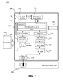
In operation, sensor 706 may be an acoustic detector or sensor/transducer (all referred to as “sensors” herein) that may operate in transmit (TX) and receive (RX) mode, or just RX mode, e.g., 20 Hz to 5 KHz. In RX mode, the sensor 706 may include one or more piezoelectric crystals that generate a voltage when force, such as sound or pressure, is applied to them. In TX mode, the piezoelectric crystals of the sensor 706 may change size when a voltage is applied across them causing them to oscillate at very high frequencies, thereby producing sound waves, e.g., 10 Hz to 10 KHz. Voltage signals generated by the sensor 706 are input to a switch 720 that outputs the received signal PLL 724, which performs a voltage to frequency conversion and gain (KHz/mV) of the received signal to an intermediate frequency (V/F to LO (intermediate frequency)+ΔF_Gain), without voltage amplification, and outputs the frequency modulated signal to the log detection converter/log detector amplifier (LDA) 726, which demodulates that frequency modulated signal at the intermediate frequency to generate an amplified pulsed output signal without a voltage gain or added noise. The amplified pulsed output signal is then shaped by the digital pulse normalization circuit 728 to create a digital-like output signal, which is then converted to a digital signal by FDC 718 so that the data signal can be processed by the water leak processing application 714 and any other applications 712 of the micro-controller 710.
The micro-controller 710 outputs a digital signal that includes data indicative of any leak detected by the sensor 706, which is then converted to an analog signal by a digital to analog converter (DAC) 730, which is then amplified by a power amplifier 732. Switch 720 may then route the amplified data signal to sensor 706 is being utilized to transmit the amplified data signal through the water medium as a means of communication. If sensor 706 is not a transmitter, the unit 700 may further include a certified data radio module 740 connected to one or more antennas 742. The data radio module 740 may include all of the circuitry and software necessary, such as RF TX, RX, ADCs, intermediate frequency synthesizers, physical layers, communication layers, memory, etc., and may communicate with any of a number of different types of fixed networks, such as a cellular wide area network (WAN), a cellular picocell network of end user subscribers, a cellular microcell network of super-user subscribers, an augmented WIFI network of super-user subscribers, a proprietary fixed wide local area network (WLAN), or an infrastructure provider network on private or ISM band (industrial, scientific and medical radio bands)
As described with respect to FIG. 7 , in FIG. 8 , voltage signals generated by the sensor 808 are input to a switch 820 that outputs the received signal to a second switch 822. The output from switch 822 is received by PLL 824, which converts the signal and outputs a frequency modulated signal to the LDA 826. The amplified pulsed output signal from the LDA 826 is then shaped by the digital pulse normalization circuit 828 and then processed by the time or flight processing application 814 and any other applications 812 of the micro-controller 810. Digital signals including data indicative of the flow rate of liquid, gas or other materials in the pipe 801, are output by the micro-controller 810, converted to analog signals by DAC 830, and routed by switch 834 to either switch 836 or switch 820. The switches 820, 822, 834 and 836 may be replace by any similar switch system, such as a switch matrix, a single double pull, double throw (DTDP) with two ins and two outs. As noted above, the unit 800 operates as a flow meter, which also requires voltage signals from sensor 806 to be routed from switch 836 to switch 822 so voltage signals from sensor 806 can be processed in the same manner as voltage signals from sensor 808, and for signals to be transmitted by sensor 808 in the same manner as sensor 806.
As illustrated in FIG. 8 , the flow meter operates using time of flight calculations. The flow rate of the liquid, gas or other material in the pipe 801 flowing in one direction, say from sensor 806 to sensor 808 may produce a faster signal from 806 to 808 than from the opposite direction of sensor 808 to sensor 806 due to the speed of the material in the pipe 801. Hence, the time taken by the signal from sensor 806 to sensor 808 minus the time from sensor 808 to sensor 806 may be proportional to the speed of the liquid. For example, if the distance from sensor 806 to sensor 808 is D, then the liquid velocity VL may be VL=K*(D/t0)*(Δt/t0), where t0 is the propagation time from sensor 806 to sensor 808 when VL=0 and Δt is the change in time due to liquid flow.
As noted above, industrial environments can be very noisy or otherwise make it difficult to utilize wireless communications because of ambient noise, RF interference, metallic partitions, moving equipment, etc., or just because the resulting wireless signals are relatively weak. By amplifying wanted wireless signals in such environments without amplifying the noise, a low noise detection system as described herein can be very useful. Other wireless applications in which the low noise detection system described herein can be desirably used include wireless communications applications that benefit from high receive sensitivity, direct analog or digital amplitude and frequency modulation AM/FM discrimination, high dynamic range, and high interference rejection. The low noise detection system described herein may be desirably utilized below 1 GHz, such as 169 MHz, 433 MHz, 868 MHz, 920 MHz, or above 1 GHz, such as 2.4 GHz, 5-6 GHz, etc., and in short range applications, such as BLUETOOTH and other personal area networks (PANs), WirelessHD and WiGig operating over the unlicensed 60 GHz spectrum, or wireless local area networks (WLAN) using analog or digital AM and FM modulations.
Due to the high receive sensitivity of the low noise detection system described herein, the regeneration of data signals without significant noise, intrinsic AM demodulation, and other factors, various medical applications may benefit using the technology, including ultrasonic monitoring, such as for blood pressure and pulse rate, magnetic resonance imaging, sonography, such ultrasonic fetus examination. FIG. 11B illustrates one such example where the wireless transmitter 1120 modulates a signal (through PLL/VCO 1122) to be transmitted at some specified frequency at a patient 1121. That signal may pass through or be reflected by the patient's tissue to receiver 1124, which includes LDA 1126 that demodulates the signal and other circuitry 1128 that finishes processing the now amplified and noise reduced signal.
Similar gains can be achieved with radio frequency identification (RFID) devices as illustrated in FIG. 11D . A typical limitation of RFID devices is that they have a short range of communication, which can make it difficult to use them for security and object tracking, such as when RFID devices are affixed to clothing or goods in stores. An RFID device that incorporates the low noise detection technology described herein, could have extended range because of the higher sensitivity, while having a relatively simple topology and lower power consumption, making it still possible to power the RFID device from the received signal. For example, the RFID transceiver 1140 could transmit a signal modulated by the PLL/VCO 1141 that is detected by the coil 1142 of the RFID transponder 1144. The coil 1142 would power the transponder 1144 and its circuitry from the received signal, which would be input to the LDA 1146, which would then demodulate the signal and other circuitry 1148, which may include the memory and the data to be transmitted back to the RFID transceiver 1140, would finish processing the now amplified and noise reduced signal.
The techniques described above may be implemented on a computing device, a plurality of computing devices, a server in communication with the computing device(s), or a plurality of servers in communication with the computing device(s). Additionally, the techniques may be distributed between the computing device(s) and the server(s). For example, the computing device may collect and transmit raw data to the server that, in turn, processes the raw data. FIG. 12 illustrates an exemplary block diagram of a computing system that includes hardware modules, software module, and a combination thereof and that can be implemented as the computing device and/or as the server.
In a basic configuration, the computing system may include at least a processor, a system memory, a storage device, input/output peripherals, communication peripherals, and an interface bus. The interface bus is configured to communicate, transmit, and transfer data, controls, and commands between the various components of the electronic device. The system memory and the storage device comprise computer readable storage media, such as RAM, ROM, EEPROM, hard-drives, CD-ROMs, optical storage devices, magnetic storage devices, flash memory, and other tangible storage media. Any of such computer readable storage medium can be configured to store instructions or program codes embodying aspects of the disclosure. Additionally, the system memory comprises an operation system and applications. The processor is configured to execute the stored instructions and can comprise, for example, a logical processing unit, a microprocessor, a digital signal processor, and the like.
The system memory and the storage device may also comprise computer readable signal media. A computer readable signal medium may include a propagated data signal with computer readable program code embodied therein. Such a propagated signal may take any of variety of forms including, but not limited to, electro-magnetic, optical, or any combination thereof. A computer readable signal medium may be any computer readable medium that is not a computer readable storage medium and that can communicate, propagate, or transport a program for use in connection with the computing system.
Further, the input and output peripherals include user interfaces such as a keyboard, screen, microphone, speaker, other input/output devices, and computing components such as digital-to-analog and analog-to-digital converters, graphical processing units, serial ports, parallel ports, and universal serial bus. The input/output peripherals may be connected to the processor through any of the ports coupled to the interface bus.
The user interfaces can be configured to allow a user of the computing system to interact with the computing system. For example, the computing system may include instructions that, when executed, cause the computing system to generate a user interface that the user can use to provide input to the computing system and to receive an output from the computing system.
This user interface may be in the form of a graphical user interface that is rendered at the screen and that is coupled with audio transmitted on the speaker and microphone and input received at the keyboard. In an embodiment, the user interface can be locally generated at the computing system. In another embodiment, the user interface may be hosted on a remote computing system and rendered at the computing system or on a remote tablet, smart phone, remote terminal, web terminal, etc. For example, the server may generate the user interface and may transmit information related thereto to the computing device that, in turn, renders the user interface to the user. The computing device may, for example, execute a browser or an application that exposes an application program interface (API) at the server to access the user interface hosted on the server.
Finally, the communication peripherals of the computing system are configured to facilitate communication between the computing system and other computing systems (e.g., between the computing device and the server) over a communications network. The communication peripherals include, for example, a network interface controller, modem, various modulators/demodulators and encoders/decoders, wireless and wired interface cards, antenna, and the like.
The communication network includes a network of any type that is suitable for providing communications between the computing device and the server and may comprise a combination of discrete networks which may use different technologies. For example, the communications network includes a cellular network, a WiFi/broadband network, a local area network (LAN), a wide area network (WAN), a telephony network, a fiber-optic network, or combinations thereof. In an example embodiment, the communication network includes the Internet and any networks adapted to communicate with the Internet. The communications network may be also configured as a means for transmitting data between the computing device and the server.
The techniques described above may be embodied in, and fully or partially automated by, code modules executed by one or more computers or computer processors. The code modules may be stored on any type of non-transitory computer-readable medium, specifically excluding signals, or computer storage device, such as hard drives, solid state memory, optical disc, and/or the like. The processes and algorithms may be implemented partially or wholly in application-specific circuitry. The results of the disclosed processes and process steps may be stored, persistently or otherwise, in any type of non-transitory computer storage such as, e.g., volatile or non-volatile storage.
The various features and processes described above may be used independently of one another, or may be combined in various ways. All possible combinations and sub-combinations are intended to fall within the scope of this disclosure. In addition, certain method or process blocks may be omitted in some implementations. The methods and processes described herein are also not limited to any particular sequence, and the blocks or states relating thereto can be performed in other sequences that are appropriate. For example, described blocks or states may be performed in an order other than that specifically disclosed, or multiple blocks or states may be combined in a single block or state. The example blocks or states may be performed in serial, in parallel, or in some other manner. Blocks or states may be added to or removed from the disclosed example embodiments. The example systems and components described herein may be configured differently than described. For example, elements may be added to, removed from, or rearranged compared to the disclosed example embodiments.
Conditional language used herein, such as, among others, “can,” “could,” “might,” “may,” “e.g.,” and the like, unless specifically stated otherwise, or otherwise understood within the context as used, is generally intended to convey that certain embodiments include, while other embodiments do not include, certain features, elements, and/or steps. Thus, such conditional language is not generally intended to imply that features, elements and/or steps are in any way required for one or more embodiments or that one or more embodiments necessarily include logic for deciding, with or without author input or prompting, whether these features, elements and/or steps are included or are to be performed in any particular embodiment. The terms “comprising,” “including,” “having,” and the like are synonymous and are used inclusively, in an open-ended fashion, and do not exclude additional elements, features, acts, operations, and so forth. Also, the term “or” is used in its inclusive sense (and not in its exclusive sense) so that when used, for example, to connect a list of elements, the term “or” means one, some, or all of the elements in the list.
In an embodiment, a low noise detection system comprises a transmitter including a modulator configured to convert a voltage signal indicative of data to a frequency signal, to modulate a baseband signal with the data, and to transmit the modulated data signal; a receiver including a log detection amplifier configured to receive the modulated data signal and to regeneratively demodulate the modulated data signal to extract the data in an amplified analog data signal while not significantly amplifying any noise in the modulated data signal; and a digital conversion circuit for converting the amplified analog signal into a digital data signal.
In the embodiment, the transmitter includes an oscillator configured to provide the modulator within an intermediate frequency signal for AM modulation and the modulator is configured to AM modulate the baseband signal with the data. In the embodiment, the modulator includes a phase lock loop (PLL) for FM modulating the baseband signal with the data. In the embodiment, the modulator includes a voltage controller oscillator (VCO) for FM modulating the baseband signal with the data. In the embodiment, the log detection amplifier includes a frequency to voltage converter configured to convert the amplified analog signal into an output voltage signal including the data. In that embodiment, the digital conversion circuit includes an N-bits analog to digital converter configured to convert the amplified analog signal into an output digital signal including the data.
In the embodiment, the digital conversion circuit includes an N-bit counter with a fast clock, a 1/N digital inverse function and a scaling circuit configured to convert the amplified analog signal into an output digital signal including the data. In the embodiment, the modulator is configured to modulate the baseband signal with a frequency tone of approximately 40 dB of high spectral purity. In the embodiment, the transmitter is a wireless transmitter operating at above or below 1 GHz and the receiver is a wireless receiver. In the embodiment, the transmitter is a medical transmission device configured to transmit the modulated data signal at a patient and the receiver is a medical receiver device configured to receive the modulated data signal passing through or being reflected by the patient, and wherein the data represents information about the patient's medical condition. In the embodiment, the transmitter is a wireless transmitter and the receiver is a wireless receiver within a user wearable device. In that embodiment, the data includes a voice signal. In that embodiment, the receiver further includes a second transmitter including a second modulator configured to convert a second voltage signal indicative of second data to a second frequency signal, to modulate a second baseband signal with the second data, and to transmit the second modulated data signal, and wherein the second data includes voice signals received by a microphone of the receiver.
In the embodiment, the transmitter is a RFID transceiver and the receiver is installed within a RFID transponder including a coil for powering the RFID transponder based on the modulated data signal and a transmitter for transmitting a code stored in a memory of the RFID transponder back to the RFID transceiver.
In the embodiment, the transmitter and the receiver are installed in a leak detector device including an ultrasonic detector configured to monitor sound or pressure in a fluid within pipe indicative of a leak of the material from the pipe.
In the embodiment, the transmitter and the receiver are installed in a flow rate monitoring device including two or more acoustic detectors configured to monitor material within a pipe indicative of a flow rate of the material.
In the embodiment, the baseband signal is a microvolt signal.
In an embodiment, a low noise detection system comprises a transmitter configured to transmit a baseband signal including a voltage data signal, and a receiver including a modulator configured to convert the voltage data signal to a frequency signal, to modulate the baseband signal with the voltage data, while not significantly amplifying noise and to output a modulated data signal, the receiver further including a log detection amplifier configured to receive the modulated data signal and to demodulate the modulated data signal to extract the data in an amplified analog data signal, and the receiver further including a digital conversion circuit for converting the amplified analog signal into a digital data signal.
In the embodiment, the log detection amplifier is configured to demodulate the modulated data signal concurrently in both AM and FM modes. In the embodiment, the receiver includes an oscillator configured to provide the modulator within an intermediate frequency signal for AM modulation and the modulator is configured to AM modulate the baseband signal based on the intermediate frequency signal with the data signal. In the embodiment, the modulator includes a phase lock loop (PLL) for FM modulating the baseband signal with the data signal. In the embodiment, the modulator includes a voltage controller oscillator (VCO) for FM modulating the baseband signal with the data signal. In the embodiment, the log detection amplifier includes a frequency to voltage converter configured to convert the amplified analog signal into an output voltage signal including data from the data signal. In that embodiment, the digital conversion circuit includes an N-bits analog to digital converter configured to convert the amplified analog signal into an output digital signal including data from the data signal.
In the embodiment, the digital conversion circuit includes a N-bit counter with fast clock, a 1/N digital inverse function and a scaling circuit configured to convert the amplified analog signal into an output digital signal including data from the data signal. In the embodiment, the modulator is configured to modulate the baseband signal with a frequency tone of approximately 40 dB of high spectral purity. In the embodiment, the transmitter is a wireless transmitter operating at above or below 1 GHz and the receiver is a wireless receiver. In the embodiment, the transmitter is a medical transmission device configured to transmit the baseband signal at a patient and the receiver is a medical receiver device configured to receive the baseband signal passing through or being reflected by the patient so as to include the data representing information about the patient's medical condition. In the embodiment, the transmitter is a medical baseband signal issued at a patient and the receiver is a medical receiver device configured to receive the baseband signal issued from the patient so as to include the data representing information about the patient's medical condition. In the embodiment, the transmitter is a wireless transmitter and the receiver is a wireless receiver within a user wearable device. In that embodiment, the data includes a voice signal. In that embodiment, the receiver further includes a second transmitter including a second modulator configured to convert a second voltage signal indicative of second data to a second frequency signal, to modulate a second baseband signal with the second data, and to transmit the second modulated data signal, and wherein the second data includes voice signals received by a microphone of the receiver.
In the embodiment, the transmitter is a RFID transceiver and the receiver is installed within a RFID transponder including a coil for powering the RFID transponder based on the baseband signal and a transmitter for transmitting a code stored in a memory of the RFID transponder back to the RFID transceiver. In the embodiment, the transmitter and the receiver are installed in a leak detector device including an acoustic detector configured to monitor sound or pressure in a fluid within pipe indicative of a leak of the material from the pipe. In the embodiment, the transmitter and the receiver are installed in a flow rate monitoring device including two or more acoustic detectors configured to monitor material within a pipe indicative of a flow rate of the material. In the embodiment, the baseband signal is a microvolt signal.
While certain example embodiments have been described, these embodiments have been presented by way of example only, and are not intended to limit the scope of the inventions disclosed herein. Thus, nothing in the foregoing description is intended to imply that any particular feature, characteristic, step, module, or block is necessary or indispensable. Indeed, the novel methods and systems described herein may be embodied in a variety of other forms; furthermore, various omissions, substitutions and changes in the form of the methods and systems described herein may be made without departing from the spirit of the inventions disclosed herein. The accompanying claims and their equivalents are intended to cover such forms or modifications as would fall within the scope and spirit of certain of the inventions disclosed herein.
Claims (34)
1. A low noise detection system, comprising:
a transmitter including a modulator configured to convert a voltage signal indicative of data to a frequency signal, to modulate a baseband signal with the data, and to transmit the modulated data signal, wherein the transmitter comprises a RFID transceiver;
a receiver including a log detection amplifier configured to receive the modulated data signal and to regeneratively demodulate the modulated data signal to extract the data in an amplified analog data signal while not significantly amplifying any noise in the modulated data signal, wherein the receiver is installed within a RFID transponder including a coil for powering the RFID transponder based on the modulated data signal and a transmitter for transmitting a code stored in a memory of the RFID transponder back to the RFID transceiver; and
a digital conversion circuit for converting the amplified analog signal into a digital data signal.
2. The low noise detection system of claim 1 , wherein the transmitter includes an oscillator configured to provide the modulator within an intermediate frequency signal for AM modulation and the modulator is configured to AM modulate the baseband signal with the data.
3. The low noise detection system of claim 1 , wherein the modulator includes a phase lock loop (PLL) for FM modulating the baseband signal with the data.
4. The low noise detection system of claim 1 , wherein the modulator includes a voltage controller oscillator (VCO) for FM modulating the baseband signal with the data.
5. The low noise detection system of claim 1 , wherein the log detection amplifier includes a frequency to voltage converter configured to convert the amplified analog signal into an output voltage signal including the data.
6. The low noise detection system of claim 5 , wherein the digital conversion circuit includes an N-bits analog to digital converter configured to convert the amplified analog signal into an output digital signal including the data.
7. The low noise detection system of claim 1 , wherein the digital conversion circuit includes a N-bit counter with a fast clock, a 1/N digital inverse function and a scaling circuit configured to convert the amplified analog signal into an output digital signal including the data.
8. The low noise detection system of claim 1 , wherein the modulator is configured to modulate the baseband signal with a frequency tone of approximately 40 dB of high spectral purity.
9. The low noise detection system of claim 1 , wherein the transmitter is a wireless transmitter operating at above or below 1 GHz and the receiver is a wireless receiver.
10. The low noise detection system of claim 1 , wherein the transmitter is a medical transmission device configured to transmit the modulated data signal at a patient and the receiver is a medical receiver device configured to receive the modulated data signal passing through or being reflected by the patient, and wherein the data represents information about the patient's medical condition.
11. The low noise detection system of claim 1 , wherein the transmitter is a wireless transmitter and the receiver is a wireless receiver within a user wearable device.
12. The low noise detection system of claim 11 , wherein the data includes a voice signal.
13. The low noise detection system of claim 11 , wherein the receiver further includes a second transmitter including a second modulator configured to convert a second voltage signal indicative of second data to a second frequency signal, to modulate a second baseband signal with the second data, and to transmit the second modulated data signal, and wherein the second data includes voice signals received by a microphone of the receiver.
14. The low noise detection system of claim 1 , wherein the transmitter and the receiver are installed in a leak detector device including an ultrasonic detector configured to monitor sound or pressure in a fluid within pipe indicative of a leak of the material from the pipe.
15. The low noise detection system of claim 1 , wherein the transmitter and the receiver are installed in a flow rate monitoring device including two or more acoustic detectors configured to monitor material within a pipe indicative of a flow rate of the material.
16. The low noise detection system of claim 1 , wherein the baseband signal is a microvolt signal.
17. A low noise detection system, comprising:
a transmitter configured to transmit a baseband signal including a voltage data signal wherein the transmitter is a RFID transceiver; and
a receiver including a modulator configured to convert the voltage data signal to a frequency signal, to modulate the baseband signal with the voltage data, while not significantly amplifying noise and to output a modulated data signal, the receiver further including a log detection amplifier configured to receive the modulated data signal and to demodulate the modulated data signal to extract the data in an amplified analog data signal, and the receiver further including a digital conversion circuit for converting the amplified analog signal into a digital data signal, wherein the receiver is installed within a RFID transponder including a coil for powering the RFID transponder based on the baseband signal and a transmitter for transmitting a code stored in a memory of the RFID transponder back to the RFID transceiver.
18. The low noise detection system of claim 17 , wherein the log detection amplifier is configured to demodulate the modulated data signal concurrently in both AM and FM modes.
19. The low noise detection system of claim 17 , wherein the receiver includes an oscillator configured to provide the modulator within an intermediate frequency signal for AM modulation and the modulator is configured to AM modulate the baseband signal based on the intermediate frequency signal with the data signal.
20. The low noise detection system of claim 17 , wherein the modulator includes a phase lock loop (PLL) for FM modulating the baseband signal with the data signal.
21. The low noise detection system of claim 17 , wherein the modulator includes a voltage controller oscillator (VCO) for FM modulating the baseband signal with the data signal.
22. The low noise detection system of claim 17 , wherein the log detection amplifier includes a frequency to voltage converter configured to convert the amplified analog signal into an output voltage signal including data from the data signal.
23. The low noise detection system of claim 22 , wherein the digital conversion circuit includes an N-bits analog to digital converter configured to convert the amplified analog signal into an output digital signal including data from the data signal.
24. The low noise detection system of claim 17 , wherein the digital conversion circuit includes a N-bit counter with fast clock, a 1/N digital inverse function and a scaling circuit configured to convert the amplified analog signal into an output digital signal including data from the data signal.
25. The low noise detection system of claim 17 , wherein the modulator is configured to modulate the baseband signal with a frequency tone of approximately 40 dB of high spectral purity.
26. The low noise detection system of claim 17 , wherein the transmitter is a wireless transmitter operating at above or below 1 GHz and the receiver is a wireless receiver.
27. The low noise detection system of claim 17 , wherein the transmitter is a medical transmission device configured to transmit the baseband signal at a patient and the receiver is a medical receiver device configured to receive the baseband signal passing through or being reflected by the patient so as to include the data representing information about the patient's medical condition.
28. The low noise detection system of claim 17 , wherein the transmitter is a medical baseband signal issued at a patient and the receiver is a medical receiver device configured to receive the baseband signal issued from the patient so as to include the data representing information about the patient's medical condition.
29. The low noise detection system of claim 17 , wherein the transmitter is a wireless transmitter and the receiver is a wireless receiver within a user wearable device.
30. The low noise detection system of claim 29 , wherein the data includes a voice signal.
31. The low noise detection system of claim 29 , wherein the receiver further includes a second transmitter including a second modulator configured to convert a second voltage signal indicative of second data to a second frequency signal, to modulate a second baseband signal with the second data, and to transmit the second modulated data signal, and wherein the second data includes voice signals received by a microphone of the receiver.
32. The low noise detection system of claim 17 , wherein the transmitter and the receiver are installed in a leak detector device including an acoustic detector configured to monitor sound or pressure in a fluid within pipe indicative of a leak of the material from the pipe.
33. The low noise detection system of claim 17 , wherein the transmitter and the receiver are installed in a flow rate monitoring device including two or more acoustic detectors configured to monitor material within a pipe indicative of a flow rate of the material.
34. The low noise detection system of claim 17 , wherein the baseband signal is a microvolt signal.
Priority Applications (1)
| Application Number | Priority Date | Filing Date | Title |
|---|---|---|---|
| US14/095,973 US9503133B2 (en) | 2012-12-03 | 2013-12-03 | Low noise detection system using log detector amplifier |
Applications Claiming Priority (2)
| Application Number | Priority Date | Filing Date | Title |
|---|---|---|---|
| US201261732848P | 2012-12-03 | 2012-12-03 | |
| US14/095,973 US9503133B2 (en) | 2012-12-03 | 2013-12-03 | Low noise detection system using log detector amplifier |
Publications (2)
| Publication Number | Publication Date |
|---|---|
| US20140154991A1 US20140154991A1 (en) | 2014-06-05 |
| US9503133B2 true US9503133B2 (en) | 2016-11-22 |
Family
ID=50824112
Family Applications (2)
| Application Number | Title | Priority Date | Filing Date |
|---|---|---|---|
| US14/095,973 Active 2034-02-23 US9503133B2 (en) | 2012-12-03 | 2013-12-03 | Low noise detection system using log detector amplifier |
| US14/095,969 Active 2034-09-09 US9621203B2 (en) | 2012-12-03 | 2013-12-03 | Medium communication system using log detector amplifier |
Family Applications After (1)
| Application Number | Title | Priority Date | Filing Date |
|---|---|---|---|
| US14/095,969 Active 2034-09-09 US9621203B2 (en) | 2012-12-03 | 2013-12-03 | Medium communication system using log detector amplifier |
Country Status (3)
| Country | Link |
|---|---|
| US (2) | US9503133B2 (en) |
| EP (2) | EP2941797B1 (en) |
| WO (2) | WO2014089123A1 (en) |
Families Citing this family (35)
| Publication number | Priority date | Publication date | Assignee | Title |
|---|---|---|---|---|
| EP2941797B1 (en) | 2012-12-03 | 2019-11-20 | Dockon AG | Low noise detection system using log detector amplifier |
| EP2974000A4 (en) | 2013-03-15 | 2017-04-05 | Dockon AG | Frequency selective logarithmic amplifier with intrinsic frequency demodulation capability |
| US9236892B2 (en) | 2013-03-15 | 2016-01-12 | Dockon Ag | Combination of steering antennas, CPL antenna(s), and one or more receive logarithmic detector amplifiers for SISO and MIMO applications |
| US9048943B2 (en) | 2013-03-15 | 2015-06-02 | Dockon Ag | Low-power, noise insensitive communication channel using logarithmic detector amplifier (LDA) demodulator |
| JP6517185B2 (en) | 2013-03-15 | 2019-05-22 | ドックオン エージー | Logarithmic amplifier with universal demodulation capability |
| US9129650B2 (en) * | 2013-07-25 | 2015-09-08 | Avago Technologies General Ip (Singapore) Pte. Ltd. | Array-reader based magnetic recording systems with frequency division multiplexing |
| US9129651B2 (en) * | 2013-08-30 | 2015-09-08 | Avago Technologies General Ip (Singapore) Pte. Ltd. | Array-reader based magnetic recording systems with quadrature amplitude modulation |
| US11082014B2 (en) | 2013-09-12 | 2021-08-03 | Dockon Ag | Advanced amplifier system for ultra-wide band RF communication |
| US11183974B2 (en) | 2013-09-12 | 2021-11-23 | Dockon Ag | Logarithmic detector amplifier system in open-loop configuration for use as high sensitivity selective receiver without frequency conversion |
| US20150070093A1 (en) | 2013-09-12 | 2015-03-12 | Dockon Ag | Logarithmic Detector Amplifier System for Use as High Sensitivity Selective Receiver Without Frequency Conversion |
| US9129648B2 (en) * | 2014-01-16 | 2015-09-08 | Avago Technologies General Ip (Singapore) Pte. Ltd. | Multiple track detection |
| KR101627793B1 (en) * | 2014-11-28 | 2016-06-07 | 주식회사 유솔 | A water meter and a waterworks controll system using the same |
| GB201508174D0 (en) * | 2015-05-13 | 2015-06-24 | Primayer Ltd | Leak noise logger |
| LT3317658T (en) * | 2015-07-03 | 2020-12-10 | Kamstrup A/S | Turbidity sensor based on ultrasound measurements |
| US9933329B2 (en) * | 2015-08-11 | 2018-04-03 | Electro Scan, Inc. | Multi-sensor inspection for identification of pressurized pipe defects that leak |
| WO2017053396A1 (en) | 2015-09-21 | 2017-03-30 | AMI Investments, LLC | Remote monitoring of water distribution system |
| JP6267250B2 (en) * | 2016-02-25 | 2018-01-24 | 株式会社Subaru | Hydraulic circuit abnormality detection device and hydraulic circuit abnormality detection method |
| US10395542B2 (en) * | 2016-03-28 | 2019-08-27 | Cisco Technology, Inc. | Drone traffic engineering |
| US20170307464A1 (en) * | 2016-04-23 | 2017-10-26 | Microphonon, Inc. | Acoustic Leak Detector |
| US10197689B1 (en) | 2016-06-24 | 2019-02-05 | The United States Of America As Represented By The Secretary Of The Navy | Physically damped noise canceling hydrophone |
| WO2019150354A1 (en) * | 2018-02-04 | 2019-08-08 | Oryx Vision Ltd. | An electronic sensing device |
| JP6936200B2 (en) * | 2018-09-28 | 2021-09-15 | 株式会社日立製作所 | Leakage detection system and method |
| EP3664301B1 (en) * | 2018-12-06 | 2021-08-18 | The Swatch Group Research and Development Ltd | Transmitter-receiver comprising an electronic chip |
| US11400328B2 (en) | 2019-06-07 | 2022-08-02 | Mueller International, Llc | Hydrant monitoring communications hub |
| US10941545B2 (en) * | 2019-06-07 | 2021-03-09 | Mueller International, Llc | Hydrant monitoring system |
| US10968609B2 (en) | 2019-06-07 | 2021-04-06 | Mueller International, Llc | Self-contained hydrant monitoring system |
| US10934693B2 (en) * | 2019-06-07 | 2021-03-02 | Mueller International, Llc | Hydrant monitoring system |
| US11359989B2 (en) * | 2019-08-05 | 2022-06-14 | Professional Flexible Technologies, Inc. | Pipeline leak detection apparatus and methods thereof |
| JP7430590B2 (en) | 2020-07-09 | 2024-02-13 | パナソニックホールディングス株式会社 | Gas leak detection system |
| WO2022093997A1 (en) * | 2020-10-27 | 2022-05-05 | SonDance Solutions LLC | Methods and systems to internally and externally locate obstructions and leaks in conveyance pipe |
| EP4019908B1 (en) * | 2020-12-28 | 2024-01-17 | Kamstrup A/S | Fluid consumption meter and method for detecting sound in a piping system |
| US11415453B1 (en) * | 2021-02-25 | 2022-08-16 | Susko Engineering, Llc | Water leak/water flow detection system |
| EP4083591A1 (en) * | 2021-04-30 | 2022-11-02 | Kamstrup A/S | Method for acoustic leak detection in a telecommunications network |
| CN113446593A (en) * | 2021-06-25 | 2021-09-28 | 吉林化工学院 | Boiler pressure-bearing pipeline leakage detection system |
| NO347674B1 (en) * | 2022-05-02 | 2024-02-19 | Ophion As | Liquid velocity meter for installation in pipes |
Citations (128)
| Publication number | Priority date | Publication date | Assignee | Title |
|---|---|---|---|---|
| US1424065A (en) | 1921-06-27 | 1922-07-25 | Edwin H Armstrong | Signaling system |
| US2363651A (en) | 1943-03-06 | 1944-11-28 | Rca Corp | Superregenerative receiver system |
| US2644081A (en) | 1948-05-22 | 1953-06-30 | Hazeltine Research Inc | Logarithmic-mode separately quenched superregenerative amplifier |
| US3092779A (en) | 1958-07-12 | 1963-06-04 | Philips Corp | Circuits for converting electric signals logarithmically for detectors and the like |
| US3199031A (en) | 1962-05-03 | 1965-08-03 | Jack R Harris | Generation and use of control signal in superregenerative receivers |
| US3320530A (en) | 1964-07-08 | 1967-05-16 | Nexus Res Lab Inc | Quasi-logarithmic multimeter for providing an output which is a linear function of the logarithmic of the input |
| US3337807A (en) | 1963-09-17 | 1967-08-22 | Hughes Aircraft Co | Superregenerative amplifier-detector |
| US3602819A (en) | 1969-05-07 | 1971-08-31 | Western Electric Co | Sensitivity or noise level measurement circuit and method |
| US3668535A (en) | 1970-01-15 | 1972-06-06 | Varian Associates | Logarithmic rf amplifier employing successive detection |
| US3724954A (en) | 1972-01-14 | 1973-04-03 | Photo Electronics Corp | Logarithmic circuit with automatic compensation for variations in conditions of operations |
| US3791272A (en) | 1972-02-07 | 1974-02-12 | Asahi Chemical Co | Automatic camera shutter controls with storage or pulse voltages |
| US3965426A (en) | 1974-01-10 | 1976-06-22 | Tandy Corporation | Frequency modulated signal pre-amplifier with amplitude modulated signal bypass |
| US4034298A (en) | 1975-10-17 | 1977-07-05 | General Electric Company | Cascode FM tuner for a radio receiver |
| US4042883A (en) | 1976-03-25 | 1977-08-16 | Motorola, Inc. | Automatic noise limiter |
| US4160953A (en) | 1977-03-11 | 1979-07-10 | Hitachi, Ltd. | Self-oscillation mixer circuits |
| JPS56138340A (en) | 1980-03-31 | 1981-10-28 | Matsushita Electric Works Ltd | Reception signal level detecting system for superregenerative receiver |
| JPS56138342A (en) | 1980-03-31 | 1981-10-28 | Matsushita Electric Works Ltd | Battery power supply type superregenerative receiver |
| US4393514A (en) | 1979-12-15 | 1983-07-12 | Matsushita Electric Works, Ltd. | Superregenerative receiver |
| US4510624A (en) | 1983-09-22 | 1985-04-09 | Motorola, Inc. | Noise blanking arrangement to minimize blanker splatter |
| JPS60249436A (en) | 1984-05-25 | 1985-12-10 | Matsushita Electric Ind Co Ltd | Input switching device of receiver |
| US4577503A (en) | 1984-09-04 | 1986-03-25 | International Business Machines Corporation | Method and device for detecting a specific acoustic spectral feature |
| US4579005A (en) | 1984-11-15 | 1986-04-01 | Manning Technologies, Inc. | Single crystal Doppler flowmeter |
| US4609994A (en) | 1984-01-16 | 1986-09-02 | The University Of Manitoba | Apparatus for continuous long-term monitoring of acoustic emission |
| US4660192A (en) | 1985-04-11 | 1987-04-21 | Pomatto Sr Robert P | Simultaneous AM and FM transmitter and receiver |
| EP0283401A2 (en) | 1987-03-18 | 1988-09-21 | Sony Corporation | FM communication device with avoidance of interference by substantially same channel fm signal |
| US4972512A (en) | 1988-02-29 | 1990-11-20 | U.S. Philips Corp. | Circuit for linearly amplifying and demodulating an AM-modulated signal, and integrated semiconductor element for such circuit |
| US4979186A (en) | 1984-12-03 | 1990-12-18 | Charles A. Phillips | Time domain radio transmission system |
| US5479442A (en) | 1992-08-31 | 1995-12-26 | Futaba Denshi Kogyo K.K. | Spectrum spread receiver and spectrum spread transmitter-receiver including same |
| US5621756A (en) | 1995-01-30 | 1997-04-15 | Motorola, Inc. | Method super-regenerative transceiver, and computer system for providing short range communication with reduced current drain |
| JPH1075273A (en) | 1996-08-30 | 1998-03-17 | Denso Corp | Reception signal amplifier |
| US5771026A (en) | 1996-03-28 | 1998-06-23 | Sti-Co Industries, Inc. | Disguised broadband antenna system for vehicles |
| US5789996A (en) | 1997-04-02 | 1998-08-04 | Harris Corporation | N-way RF power combiner/divider |
| US5818875A (en) * | 1995-04-11 | 1998-10-06 | Nippon Telegraph And Telephone Corporation | Modulation and demodulation method, modulator and demodulator |
| US5995814A (en) | 1997-06-13 | 1999-11-30 | Lucent Technologies Inc. | Single-stage dual-band low-noise amplifier for use in a wireless communication system receiver |
| US6035002A (en) | 1995-06-05 | 2000-03-07 | The Chamberlain Group, Inc. | Digital super-regenerative detector RF receiver |
| US6054900A (en) | 1998-03-09 | 2000-04-25 | Matsushita Electric Industrial Co., Ltd. | Power amplifier MMIC and mobile communication terminal |
| WO2000035124A2 (en) | 1998-12-08 | 2000-06-15 | Telital R & D Denmark | Dual antenna system |
| GB2354329A (en) | 1999-06-22 | 2001-03-21 | Axon Instr Ltd | Flow meter |
| US20010037676A1 (en) | 1998-09-03 | 2001-11-08 | Chang Hak Soo | Ultrasonic flow velocity measuring method |
| US6389275B1 (en) | 1998-06-30 | 2002-05-14 | Omron Corporation | Signal receiver and method thereof, transceiver, and network system |
| US6421535B1 (en) | 1999-05-12 | 2002-07-16 | Xetron Corporation | Superregenerative circuit |
| US6420937B1 (en) | 2000-08-29 | 2002-07-16 | Matsushita Electric Industrial Co., Ltd. | Voltage controlled oscillator with power amplifier |
| US20020109607A1 (en) | 2000-07-21 | 2002-08-15 | Itron, Inc. | Spread spectrum meter reading system utilizing low-speed/high-power frequency hopping |
| WO2002084782A2 (en) | 2001-04-11 | 2002-10-24 | Kyocera Wireless Corporation | Antenna interface unit |
| US6518856B1 (en) | 1999-10-13 | 2003-02-11 | Signal Technology Corporation | RF power divider/combiner circuit |
| US6538528B2 (en) | 2000-06-29 | 2003-03-25 | Thomson Licensing S.A. | T-circuit produced using microstrip technology with a phase-shifting element |
| US6574287B1 (en) | 1999-01-27 | 2003-06-03 | Conexant Systems, Inc. | Frequency/Phase comparison circuit with gated reference and signal inputs |
| US6668165B1 (en) | 1998-11-09 | 2003-12-23 | Skyworks Solutions, Inc. | Inverted super regenerative receiver |
| US6671331B1 (en) * | 1998-11-18 | 2003-12-30 | Nec Corporation | Carrier detecting circuit for detecting the level of a received signal and communication apparatus |
| US6668619B2 (en) | 1999-05-27 | 2003-12-30 | Acoustic Systems, Inc. | Pattern matching for real time leak detection and location in pipelines |
| US6670849B1 (en) | 2000-08-30 | 2003-12-30 | Skyworks Solutions, Inc. | System for closed loop power control using a linear or a non-linear power amplifier |
| US20040229585A1 (en) | 2003-05-14 | 2004-11-18 | Yi Lu | Super-regenerative radio frequency receiver and its data receiving method |
| US20040240588A1 (en) | 2001-08-31 | 2004-12-02 | Miller William J. | Compensation for non-linear distortion in a modem receiver |
| US20050003785A1 (en) * | 2002-07-23 | 2005-01-06 | Jackson Paul K. W. | Wideband signal generators, measurement devices, methods of signal generation, and methods of signal analysis |
| US20050009480A1 (en) * | 2000-09-20 | 2005-01-13 | Vakilian Nooshin D. | System and method for allowing a TDMA/CDMA portable transceiver to operate with closed loop power control |
| US20050069051A1 (en) | 2003-09-25 | 2005-03-31 | Microchip Technology Incorporated | Q-quenching super-regenerative receiver |
| US20050270172A1 (en) | 2001-07-13 | 2005-12-08 | Exxonmobil Upstream Research Company | Method and apparatus for using a data telemetry system over multi-conductor wirelines |
| US20060028297A1 (en) | 2004-08-04 | 2006-02-09 | Samsung Electronics Co., Ltd. | Power divider and combiner in communication system |
| US20060226897A1 (en) | 2005-04-06 | 2006-10-12 | Integration Associates Inc. | Differential slope demodulator for low-IF frequencies |
| US20070030099A1 (en) | 2005-07-01 | 2007-02-08 | Stmicroelectronics S.A. | Band pass filtering circuit fitted with acoustic resonators |
| US20070066265A1 (en) | 2005-09-22 | 2007-03-22 | May Michael R | Method to adjustably convert a first data signal having a first time domain to a second data signal having a second time domain |
| US7215936B2 (en) | 2003-04-02 | 2007-05-08 | Bogdan Sadowski | Super-regenerative receiver including phase-locked loop |
| US20070105521A1 (en) | 2005-10-12 | 2007-05-10 | Stmicroelectronics S.R.L. | Notch filter and apparatus for receiving and transmitting radio-frequency signals incorporating same |
| US20070139130A1 (en) | 2005-12-19 | 2007-06-21 | Samsung Electro-Mechanics Co., Ltd. | Super-regenerative receiver |
| US20070207749A1 (en) * | 2006-01-31 | 2007-09-06 | Dmitriy Rozenblit | System and method for power mapping to compensate for power amplifier gain control variations |
| WO2008018836A1 (en) | 2006-08-07 | 2008-02-14 | Agency For Science, Technology And Research | Self-powered in-pipe fluid meter and piping network comprising a plurality of such fluid meters |
| US20080101185A1 (en) * | 2006-10-30 | 2008-05-01 | Dmitriy Rozenblit | System and method for closed loop power control calibration |
| WO2008075066A2 (en) | 2006-12-20 | 2008-06-26 | The University Of Sheffield | Leak detection device in fluid filled pipelines |
| US7400904B2 (en) | 2004-12-03 | 2008-07-15 | Itron, Inc. | Dual mode AM-FM receiver with I-Q decoding, such as for utility data collection |
| US20080176529A1 (en) | 2007-01-19 | 2008-07-24 | Lexiwave Technology (Hong Kong), Limited | Superregenerative system |
| US7423931B2 (en) | 2003-07-08 | 2008-09-09 | Lawrence Livermore National Security, Llc | Acoustic system for communication in pipelines |
| US20080269841A1 (en) | 2007-04-30 | 2008-10-30 | Medtronic, Inc. | Chopper mixer telemetry circuit |
| US20090079524A1 (en) | 2004-02-10 | 2009-03-26 | Bitwave Semiconductor, Inc. | Multi-band tunable resonant circuit |
| US20090079607A1 (en) | 2007-09-26 | 2009-03-26 | Medtronic, Inc. | Chopper-stabilized analog-to-digital converter |
| US20090147837A1 (en) | 2007-12-07 | 2009-06-11 | Eddie Lau | Wireless system synchronization using frequency shift modulation and on-off keying modulation |
| US7567099B2 (en) | 2007-05-01 | 2009-07-28 | Dialogic Corporation | Filterless digital frequency locked loop |
| US7612616B2 (en) | 2008-01-25 | 2009-11-03 | National Taiwan University | Low-noise amplifier |
| US20090322544A1 (en) | 2008-06-27 | 2009-12-31 | Exxonmobil Research And Engineering Company | Method and apparatus for real time enhancing of the operation of a fluid transport pipeline |
| US20100080270A1 (en) | 2007-01-26 | 2010-04-01 | Agency For Science, Technology And Research | Radio frequency indentification transceiver |
| US20100152644A1 (en) | 2007-03-19 | 2010-06-17 | Insuline Medical Ltd. | Method and device for drug delivery |
| US7751996B1 (en) | 2006-12-12 | 2010-07-06 | Sprint Communications Company L.P. | Measurement system for determining desired/undesired ratio of wireless video signals |
| US7751857B2 (en) | 2005-02-16 | 2010-07-06 | Microtune (Texas), L.P. | Radio-frequency amplifier system |
| US20100225417A1 (en) | 2009-03-03 | 2010-09-09 | Selex Galileo S.P.A. | N-Way Divider/Combiner, With N Different From A Power Of Two, Obtained In Planar, Monolithic, And Single-Face Technology For Distribution Networks For Avionic Radars With Electronic Beam-Scanning Antenna |
| US7819022B2 (en) | 2006-03-16 | 2010-10-26 | Sensorteknikk As | Method and device for recording characteristic state, amount and composition of a flowing medium |
| US7848384B2 (en) | 2006-03-03 | 2010-12-07 | Commissariat A L'energie Atomique | Device and method for ultrawideband reception using a super-regenerative detector |
| US20100308999A1 (en) * | 2009-06-05 | 2010-12-09 | Chornenky Todd E | Security and monitoring apparatus |
| US20100313958A1 (en) | 2009-06-11 | 2010-12-16 | University Of Washington | Sensing events affecting liquid flow in a liquid distribution system |
| US20110007844A1 (en) | 2007-07-03 | 2011-01-13 | Electronics And Telecommunications Research Institute | Apparatus for frequency modulating and demodulating of frequency selective baseband with gain of frequency diversity, and apparatus for transmitting and receiving using for this |
| US20110018777A1 (en) | 2008-03-26 | 2011-01-27 | Viditech Ag | Self-contained counterpoise compound loop antenna |
| US20110037516A1 (en) | 2009-08-03 | 2011-02-17 | Qualcomm Incorporated | Multi-stage impedance matching |
| US7911235B2 (en) | 2007-11-01 | 2011-03-22 | Dockon Ag | Logarithmic detectors |
| US20110093220A1 (en) | 2009-10-21 | 2011-04-21 | ACOUSTIC SYSTEMS,Inc. | Integrated acoustic leak detection system using intrusive and non-intrusive sensors |
| US20110212692A1 (en) | 2010-02-26 | 2011-09-01 | Intersil Americas Inc. | Cascaded Filter Based Noise and Interference Canceller |
| US20110234316A1 (en) | 2010-03-26 | 2011-09-29 | Avago Technologies Wireless Ip (Singapore) Pte. Ltd. | Impedance matching circuit capable of efficiently isolating paths for multi-band power amplifier |
| US8040204B2 (en) | 2008-07-01 | 2011-10-18 | Dockon Ag | Radio frequency combiners/splitters |
| US8064864B2 (en) | 2006-09-28 | 2011-11-22 | Broadcom Corporation | RFID using an hybrid on-chip-off-chip transformer |
| US20110301882A1 (en) | 2009-02-23 | 2011-12-08 | Morten Ivar Andersen | System and method for passive acoustic monitoring of fluids and solids in pipe flow |
| US20120019336A1 (en) | 2010-01-12 | 2012-01-26 | Xg Technology, Inc. | Low loss RF transceiver combiner |
| US8144065B2 (en) | 2008-03-26 | 2012-03-27 | Dockon Ag | Planar compound loop antenna |
| US8164532B1 (en) | 2011-01-18 | 2012-04-24 | Dockon Ag | Circular polarized compound loop antenna |
| US20120106560A1 (en) | 2010-11-01 | 2012-05-03 | Indian Institute Of Technology Bombay | Inter-domain routing in an n-ary-tree and source-routing based communication framework |
| US20120112852A1 (en) | 2010-11-08 | 2012-05-10 | Paratek Microwave, Inc. | Method and apparatus for tuning antennas in a communication device |
| US20120121030A1 (en) | 2010-11-12 | 2012-05-17 | Microsoft Corporation | Compressive Wireless Modulation |
| US20120164644A1 (en) | 2010-10-22 | 2012-06-28 | T2 Biosystems, Inc. | Nmr systems and methods for the rapid detection of analytes |
| US20120190317A1 (en) | 2011-01-24 | 2012-07-26 | Baudouin Martineau | Radio frequency combiner |
| US8265769B2 (en) * | 2007-01-31 | 2012-09-11 | Medtronic, Inc. | Chopper-stabilized instrumentation amplifier for wireless telemetry |
| US20120280754A1 (en) | 2011-05-02 | 2012-11-08 | Rfaxis, Inc. | Power amplifier with co-existence filter |
| WO2012153147A1 (en) | 2011-05-11 | 2012-11-15 | Syrinix Limited | Pipeline fault detection system, sensor head and method of detecting pipeline faults |
| US8326340B2 (en) | 2008-01-31 | 2012-12-04 | Mediatek Inc. | Transmit power controller |
| US8364098B2 (en) | 2007-11-02 | 2013-01-29 | St-Ericsson Sa | PLL calibration |
| US20130029350A1 (en) | 2010-01-22 | 2013-01-31 | Alere Switzerland Gmbh | Bi-stable oscillator |
| US8368485B2 (en) | 2008-07-01 | 2013-02-05 | Dockon Ag | Radio frequency combiners/splitters |
| US8385910B2 (en) * | 2004-05-20 | 2013-02-26 | Qualcomm Incorporated | Systems and methods for testing signal processing control |
| US20130059548A1 (en) | 2011-09-06 | 2013-03-07 | Kabushiki Kaisha Toshiba | Oscillator and radio communication device |
| US20130113666A1 (en) | 2011-11-04 | 2013-05-09 | Dockon Ag | Capacitively coupled compound loop antenna |
| US20130128934A1 (en) | 2011-11-18 | 2013-05-23 | Joon Seong KANG | Receiver and transmitter of coping with interference in super-regenerative communication system, and method of using the receiver and the transmitter |
| US8462031B2 (en) | 2010-02-15 | 2013-06-11 | Stmicroelectronics Sa | Continuous time analogue/digital converter |
| US20130222058A1 (en) | 2012-02-29 | 2013-08-29 | Fujitsu Limited | Amplifier |
| US8542768B2 (en) | 2009-12-21 | 2013-09-24 | Dali Systems Co. Ltd. | High efficiency, remotely reconfigurable remote radio head unit system and method for wireless communications |
| US8644776B1 (en) | 2008-08-25 | 2014-02-04 | Peregrine Semiconductor Corporation | Systems and methods for providing improved power performance in wireless communication systems |
| US8655441B2 (en) * | 2009-04-16 | 2014-02-18 | Massachusetts Institute Of Technology | Methods and apparatus for monitoring patients and delivering therapeutic stimuli |
| US8676521B2 (en) | 2009-10-26 | 2014-03-18 | Fluke Corporation | System and method for handling wide dynamic range signals encountered in vibration analysis using a logarithmic amplifier |
| US20140150554A1 (en) | 2012-12-03 | 2014-06-05 | DockOn A.G. | Medium communication system using log detector amplifier |
| US20140171002A1 (en) | 2012-12-13 | 2014-06-19 | Samsung Electronics Co., Ltd. | Apparatus and method to adaptively set threshold to detect transmission symbol in ook receiver |
| US20140266962A1 (en) | 2013-03-15 | 2014-09-18 | Dockon Ag | Power Combiner and Fixed/Adjustable CPL Antennas |
| US20140269972A1 (en) | 2013-03-15 | 2014-09-18 | Dockon Ag | Low-Power, Noise Insensitive Communication Channel using Logarithmic Detector Amplifier (LDA) Demodulator |
| US20140273898A1 (en) | 2013-03-15 | 2014-09-18 | Dockon Ag | Frequency Selective Logarithmic Amplifier With Intrinsic Frequency Demodulation Capability |
| US20140287704A1 (en) | 2013-03-15 | 2014-09-25 | Dockon Ag | Combination of steering antennas, cpl antenna(s), and one or more receive logarithmic detector amplifiers for siso and mimo applications |
Family Cites Families (3)
| Publication number | Priority date | Publication date | Assignee | Title |
|---|---|---|---|---|
| JP2001099929A (en) * | 1999-09-30 | 2001-04-13 | Toshiba Corp | Radar device for secondary monitoring |
| FR2815791B1 (en) | 2000-10-24 | 2003-03-07 | France Telecom | METHOD FOR TRANSFORMING BANDPASS FILTERS TO FACILITATE THEIR PRODUCTION, AND DEVICES OBTAINED THEREBY |
| CN201708879U (en) * | 2010-02-10 | 2011-01-12 | 丽羽电子股份有限公司 | Noise inhibitor |
-
2013
- 2013-12-03 EP EP13859934.5A patent/EP2941797B1/en active Active
- 2013-12-03 US US14/095,973 patent/US9503133B2/en active Active
- 2013-12-03 EP EP13860466.5A patent/EP2926109B1/en active Active
- 2013-12-03 US US14/095,969 patent/US9621203B2/en active Active
- 2013-12-03 WO PCT/US2013/072937 patent/WO2014089123A1/en active Application Filing
- 2013-12-03 WO PCT/US2013/072935 patent/WO2014089122A1/en active Application Filing
Patent Citations (132)
| Publication number | Priority date | Publication date | Assignee | Title |
|---|---|---|---|---|
| US1424065A (en) | 1921-06-27 | 1922-07-25 | Edwin H Armstrong | Signaling system |
| US2363651A (en) | 1943-03-06 | 1944-11-28 | Rca Corp | Superregenerative receiver system |
| US2644081A (en) | 1948-05-22 | 1953-06-30 | Hazeltine Research Inc | Logarithmic-mode separately quenched superregenerative amplifier |
| US3092779A (en) | 1958-07-12 | 1963-06-04 | Philips Corp | Circuits for converting electric signals logarithmically for detectors and the like |
| US3199031A (en) | 1962-05-03 | 1965-08-03 | Jack R Harris | Generation and use of control signal in superregenerative receivers |
| US3337807A (en) | 1963-09-17 | 1967-08-22 | Hughes Aircraft Co | Superregenerative amplifier-detector |
| US3320530A (en) | 1964-07-08 | 1967-05-16 | Nexus Res Lab Inc | Quasi-logarithmic multimeter for providing an output which is a linear function of the logarithmic of the input |
| US3602819A (en) | 1969-05-07 | 1971-08-31 | Western Electric Co | Sensitivity or noise level measurement circuit and method |
| US3668535A (en) | 1970-01-15 | 1972-06-06 | Varian Associates | Logarithmic rf amplifier employing successive detection |
| US3724954A (en) | 1972-01-14 | 1973-04-03 | Photo Electronics Corp | Logarithmic circuit with automatic compensation for variations in conditions of operations |
| US3791272A (en) | 1972-02-07 | 1974-02-12 | Asahi Chemical Co | Automatic camera shutter controls with storage or pulse voltages |
| US3965426A (en) | 1974-01-10 | 1976-06-22 | Tandy Corporation | Frequency modulated signal pre-amplifier with amplitude modulated signal bypass |
| US4034298A (en) | 1975-10-17 | 1977-07-05 | General Electric Company | Cascode FM tuner for a radio receiver |
| US4042883A (en) | 1976-03-25 | 1977-08-16 | Motorola, Inc. | Automatic noise limiter |
| US4160953A (en) | 1977-03-11 | 1979-07-10 | Hitachi, Ltd. | Self-oscillation mixer circuits |
| US4393514A (en) | 1979-12-15 | 1983-07-12 | Matsushita Electric Works, Ltd. | Superregenerative receiver |
| JPS56138340A (en) | 1980-03-31 | 1981-10-28 | Matsushita Electric Works Ltd | Reception signal level detecting system for superregenerative receiver |
| JPS56138342A (en) | 1980-03-31 | 1981-10-28 | Matsushita Electric Works Ltd | Battery power supply type superregenerative receiver |
| US4510624A (en) | 1983-09-22 | 1985-04-09 | Motorola, Inc. | Noise blanking arrangement to minimize blanker splatter |
| US4609994A (en) | 1984-01-16 | 1986-09-02 | The University Of Manitoba | Apparatus for continuous long-term monitoring of acoustic emission |
| JPS60249436A (en) | 1984-05-25 | 1985-12-10 | Matsushita Electric Ind Co Ltd | Input switching device of receiver |
| US4577503A (en) | 1984-09-04 | 1986-03-25 | International Business Machines Corporation | Method and device for detecting a specific acoustic spectral feature |
| US4579005A (en) | 1984-11-15 | 1986-04-01 | Manning Technologies, Inc. | Single crystal Doppler flowmeter |
| US4979186A (en) | 1984-12-03 | 1990-12-18 | Charles A. Phillips | Time domain radio transmission system |
| US4660192A (en) | 1985-04-11 | 1987-04-21 | Pomatto Sr Robert P | Simultaneous AM and FM transmitter and receiver |
| EP0283401A2 (en) | 1987-03-18 | 1988-09-21 | Sony Corporation | FM communication device with avoidance of interference by substantially same channel fm signal |
| US4882768A (en) | 1987-03-18 | 1989-11-21 | Sony Corporation | FM communication device with avoidance of interference by substantially same channel FM signal |
| US4972512A (en) | 1988-02-29 | 1990-11-20 | U.S. Philips Corp. | Circuit for linearly amplifying and demodulating an AM-modulated signal, and integrated semiconductor element for such circuit |
| US5479442A (en) | 1992-08-31 | 1995-12-26 | Futaba Denshi Kogyo K.K. | Spectrum spread receiver and spectrum spread transmitter-receiver including same |
| US5621756A (en) | 1995-01-30 | 1997-04-15 | Motorola, Inc. | Method super-regenerative transceiver, and computer system for providing short range communication with reduced current drain |
| US5818875A (en) * | 1995-04-11 | 1998-10-06 | Nippon Telegraph And Telephone Corporation | Modulation and demodulation method, modulator and demodulator |
| US6035002A (en) | 1995-06-05 | 2000-03-07 | The Chamberlain Group, Inc. | Digital super-regenerative detector RF receiver |
| US5771026A (en) | 1996-03-28 | 1998-06-23 | Sti-Co Industries, Inc. | Disguised broadband antenna system for vehicles |
| JPH1075273A (en) | 1996-08-30 | 1998-03-17 | Denso Corp | Reception signal amplifier |
| US5789996A (en) | 1997-04-02 | 1998-08-04 | Harris Corporation | N-way RF power combiner/divider |
| US5995814A (en) | 1997-06-13 | 1999-11-30 | Lucent Technologies Inc. | Single-stage dual-band low-noise amplifier for use in a wireless communication system receiver |
| US6054900A (en) | 1998-03-09 | 2000-04-25 | Matsushita Electric Industrial Co., Ltd. | Power amplifier MMIC and mobile communication terminal |
| US6389275B1 (en) | 1998-06-30 | 2002-05-14 | Omron Corporation | Signal receiver and method thereof, transceiver, and network system |
| US20010037676A1 (en) | 1998-09-03 | 2001-11-08 | Chang Hak Soo | Ultrasonic flow velocity measuring method |
| US6668165B1 (en) | 1998-11-09 | 2003-12-23 | Skyworks Solutions, Inc. | Inverted super regenerative receiver |
| US6671331B1 (en) * | 1998-11-18 | 2003-12-30 | Nec Corporation | Carrier detecting circuit for detecting the level of a received signal and communication apparatus |
| WO2000035124A2 (en) | 1998-12-08 | 2000-06-15 | Telital R & D Denmark | Dual antenna system |
| US6574287B1 (en) | 1999-01-27 | 2003-06-03 | Conexant Systems, Inc. | Frequency/Phase comparison circuit with gated reference and signal inputs |
| US6421535B1 (en) | 1999-05-12 | 2002-07-16 | Xetron Corporation | Superregenerative circuit |
| US6668619B2 (en) | 1999-05-27 | 2003-12-30 | Acoustic Systems, Inc. | Pattern matching for real time leak detection and location in pipelines |
| GB2354329A (en) | 1999-06-22 | 2001-03-21 | Axon Instr Ltd | Flow meter |
| US6518856B1 (en) | 1999-10-13 | 2003-02-11 | Signal Technology Corporation | RF power divider/combiner circuit |
| US6538528B2 (en) | 2000-06-29 | 2003-03-25 | Thomson Licensing S.A. | T-circuit produced using microstrip technology with a phase-shifting element |
| US20020109607A1 (en) | 2000-07-21 | 2002-08-15 | Itron, Inc. | Spread spectrum meter reading system utilizing low-speed/high-power frequency hopping |
| US6420937B1 (en) | 2000-08-29 | 2002-07-16 | Matsushita Electric Industrial Co., Ltd. | Voltage controlled oscillator with power amplifier |
| US6670849B1 (en) | 2000-08-30 | 2003-12-30 | Skyworks Solutions, Inc. | System for closed loop power control using a linear or a non-linear power amplifier |
| US20050009480A1 (en) * | 2000-09-20 | 2005-01-13 | Vakilian Nooshin D. | System and method for allowing a TDMA/CDMA portable transceiver to operate with closed loop power control |
| WO2002084782A2 (en) | 2001-04-11 | 2002-10-24 | Kyocera Wireless Corporation | Antenna interface unit |
| EP1384281A2 (en) | 2001-04-11 | 2004-01-28 | Kyocera Wireless Corporation | Antenna interface unit |
| US20050270172A1 (en) | 2001-07-13 | 2005-12-08 | Exxonmobil Upstream Research Company | Method and apparatus for using a data telemetry system over multi-conductor wirelines |
| US20040240588A1 (en) | 2001-08-31 | 2004-12-02 | Miller William J. | Compensation for non-linear distortion in a modem receiver |
| US20050003785A1 (en) * | 2002-07-23 | 2005-01-06 | Jackson Paul K. W. | Wideband signal generators, measurement devices, methods of signal generation, and methods of signal analysis |
| US7215936B2 (en) | 2003-04-02 | 2007-05-08 | Bogdan Sadowski | Super-regenerative receiver including phase-locked loop |
| US20040229585A1 (en) | 2003-05-14 | 2004-11-18 | Yi Lu | Super-regenerative radio frequency receiver and its data receiving method |
| US7423931B2 (en) | 2003-07-08 | 2008-09-09 | Lawrence Livermore National Security, Llc | Acoustic system for communication in pipelines |
| US20050069051A1 (en) | 2003-09-25 | 2005-03-31 | Microchip Technology Incorporated | Q-quenching super-regenerative receiver |
| US20090079524A1 (en) | 2004-02-10 | 2009-03-26 | Bitwave Semiconductor, Inc. | Multi-band tunable resonant circuit |
| US8385910B2 (en) * | 2004-05-20 | 2013-02-26 | Qualcomm Incorporated | Systems and methods for testing signal processing control |
| US20060028297A1 (en) | 2004-08-04 | 2006-02-09 | Samsung Electronics Co., Ltd. | Power divider and combiner in communication system |
| US7400904B2 (en) | 2004-12-03 | 2008-07-15 | Itron, Inc. | Dual mode AM-FM receiver with I-Q decoding, such as for utility data collection |
| US7751857B2 (en) | 2005-02-16 | 2010-07-06 | Microtune (Texas), L.P. | Radio-frequency amplifier system |
| US20060226897A1 (en) | 2005-04-06 | 2006-10-12 | Integration Associates Inc. | Differential slope demodulator for low-IF frequencies |
| US20070030099A1 (en) | 2005-07-01 | 2007-02-08 | Stmicroelectronics S.A. | Band pass filtering circuit fitted with acoustic resonators |
| US20070066265A1 (en) | 2005-09-22 | 2007-03-22 | May Michael R | Method to adjustably convert a first data signal having a first time domain to a second data signal having a second time domain |
| US20070105521A1 (en) | 2005-10-12 | 2007-05-10 | Stmicroelectronics S.R.L. | Notch filter and apparatus for receiving and transmitting radio-frequency signals incorporating same |
| US20070139130A1 (en) | 2005-12-19 | 2007-06-21 | Samsung Electro-Mechanics Co., Ltd. | Super-regenerative receiver |
| US20070207749A1 (en) * | 2006-01-31 | 2007-09-06 | Dmitriy Rozenblit | System and method for power mapping to compensate for power amplifier gain control variations |
| US7848384B2 (en) | 2006-03-03 | 2010-12-07 | Commissariat A L'energie Atomique | Device and method for ultrawideband reception using a super-regenerative detector |
| US7819022B2 (en) | 2006-03-16 | 2010-10-26 | Sensorteknikk As | Method and device for recording characteristic state, amount and composition of a flowing medium |
| WO2008018836A1 (en) | 2006-08-07 | 2008-02-14 | Agency For Science, Technology And Research | Self-powered in-pipe fluid meter and piping network comprising a plurality of such fluid meters |
| US8064864B2 (en) | 2006-09-28 | 2011-11-22 | Broadcom Corporation | RFID using an hybrid on-chip-off-chip transformer |
| US20080101185A1 (en) * | 2006-10-30 | 2008-05-01 | Dmitriy Rozenblit | System and method for closed loop power control calibration |
| US7751996B1 (en) | 2006-12-12 | 2010-07-06 | Sprint Communications Company L.P. | Measurement system for determining desired/undesired ratio of wireless video signals |
| WO2008075066A2 (en) | 2006-12-20 | 2008-06-26 | The University Of Sheffield | Leak detection device in fluid filled pipelines |
| US20080176529A1 (en) | 2007-01-19 | 2008-07-24 | Lexiwave Technology (Hong Kong), Limited | Superregenerative system |
| US20100080270A1 (en) | 2007-01-26 | 2010-04-01 | Agency For Science, Technology And Research | Radio frequency indentification transceiver |
| US8265769B2 (en) * | 2007-01-31 | 2012-09-11 | Medtronic, Inc. | Chopper-stabilized instrumentation amplifier for wireless telemetry |
| US20100152644A1 (en) | 2007-03-19 | 2010-06-17 | Insuline Medical Ltd. | Method and device for drug delivery |
| US20080269841A1 (en) | 2007-04-30 | 2008-10-30 | Medtronic, Inc. | Chopper mixer telemetry circuit |
| US7567099B2 (en) | 2007-05-01 | 2009-07-28 | Dialogic Corporation | Filterless digital frequency locked loop |
| US20110007844A1 (en) | 2007-07-03 | 2011-01-13 | Electronics And Telecommunications Research Institute | Apparatus for frequency modulating and demodulating of frequency selective baseband with gain of frequency diversity, and apparatus for transmitting and receiving using for this |
| US20090079607A1 (en) | 2007-09-26 | 2009-03-26 | Medtronic, Inc. | Chopper-stabilized analog-to-digital converter |
| US7911235B2 (en) | 2007-11-01 | 2011-03-22 | Dockon Ag | Logarithmic detectors |
| US8364098B2 (en) | 2007-11-02 | 2013-01-29 | St-Ericsson Sa | PLL calibration |
| US20090147837A1 (en) | 2007-12-07 | 2009-06-11 | Eddie Lau | Wireless system synchronization using frequency shift modulation and on-off keying modulation |
| US7612616B2 (en) | 2008-01-25 | 2009-11-03 | National Taiwan University | Low-noise amplifier |
| US8326340B2 (en) | 2008-01-31 | 2012-12-04 | Mediatek Inc. | Transmit power controller |
| US8144065B2 (en) | 2008-03-26 | 2012-03-27 | Dockon Ag | Planar compound loop antenna |
| US20110018777A1 (en) | 2008-03-26 | 2011-01-27 | Viditech Ag | Self-contained counterpoise compound loop antenna |
| US8149173B2 (en) | 2008-03-26 | 2012-04-03 | Dockon Ag | Modified loop antenna |
| US20090322544A1 (en) | 2008-06-27 | 2009-12-31 | Exxonmobil Research And Engineering Company | Method and apparatus for real time enhancing of the operation of a fluid transport pipeline |
| US8368485B2 (en) | 2008-07-01 | 2013-02-05 | Dockon Ag | Radio frequency combiners/splitters |
| US8040204B2 (en) | 2008-07-01 | 2011-10-18 | Dockon Ag | Radio frequency combiners/splitters |
| US8644776B1 (en) | 2008-08-25 | 2014-02-04 | Peregrine Semiconductor Corporation | Systems and methods for providing improved power performance in wireless communication systems |
| US20110301882A1 (en) | 2009-02-23 | 2011-12-08 | Morten Ivar Andersen | System and method for passive acoustic monitoring of fluids and solids in pipe flow |
| US20100225417A1 (en) | 2009-03-03 | 2010-09-09 | Selex Galileo S.P.A. | N-Way Divider/Combiner, With N Different From A Power Of Two, Obtained In Planar, Monolithic, And Single-Face Technology For Distribution Networks For Avionic Radars With Electronic Beam-Scanning Antenna |
| US8655441B2 (en) * | 2009-04-16 | 2014-02-18 | Massachusetts Institute Of Technology | Methods and apparatus for monitoring patients and delivering therapeutic stimuli |
| US20100308999A1 (en) * | 2009-06-05 | 2010-12-09 | Chornenky Todd E | Security and monitoring apparatus |
| US20100313958A1 (en) | 2009-06-11 | 2010-12-16 | University Of Washington | Sensing events affecting liquid flow in a liquid distribution system |
| US20110037516A1 (en) | 2009-08-03 | 2011-02-17 | Qualcomm Incorporated | Multi-stage impedance matching |
| US20110093220A1 (en) | 2009-10-21 | 2011-04-21 | ACOUSTIC SYSTEMS,Inc. | Integrated acoustic leak detection system using intrusive and non-intrusive sensors |
| US8676521B2 (en) | 2009-10-26 | 2014-03-18 | Fluke Corporation | System and method for handling wide dynamic range signals encountered in vibration analysis using a logarithmic amplifier |
| US8542768B2 (en) | 2009-12-21 | 2013-09-24 | Dali Systems Co. Ltd. | High efficiency, remotely reconfigurable remote radio head unit system and method for wireless communications |
| US20120019336A1 (en) | 2010-01-12 | 2012-01-26 | Xg Technology, Inc. | Low loss RF transceiver combiner |
| US20130029350A1 (en) | 2010-01-22 | 2013-01-31 | Alere Switzerland Gmbh | Bi-stable oscillator |
| US8462031B2 (en) | 2010-02-15 | 2013-06-11 | Stmicroelectronics Sa | Continuous time analogue/digital converter |
| US20110212692A1 (en) | 2010-02-26 | 2011-09-01 | Intersil Americas Inc. | Cascaded Filter Based Noise and Interference Canceller |
| US20110234316A1 (en) | 2010-03-26 | 2011-09-29 | Avago Technologies Wireless Ip (Singapore) Pte. Ltd. | Impedance matching circuit capable of efficiently isolating paths for multi-band power amplifier |
| US20120164644A1 (en) | 2010-10-22 | 2012-06-28 | T2 Biosystems, Inc. | Nmr systems and methods for the rapid detection of analytes |
| US20120106560A1 (en) | 2010-11-01 | 2012-05-03 | Indian Institute Of Technology Bombay | Inter-domain routing in an n-ary-tree and source-routing based communication framework |
| US20120112852A1 (en) | 2010-11-08 | 2012-05-10 | Paratek Microwave, Inc. | Method and apparatus for tuning antennas in a communication device |
| US20120121030A1 (en) | 2010-11-12 | 2012-05-17 | Microsoft Corporation | Compressive Wireless Modulation |
| US8164532B1 (en) | 2011-01-18 | 2012-04-24 | Dockon Ag | Circular polarized compound loop antenna |
| US20120190317A1 (en) | 2011-01-24 | 2012-07-26 | Baudouin Martineau | Radio frequency combiner |
| US20120280754A1 (en) | 2011-05-02 | 2012-11-08 | Rfaxis, Inc. | Power amplifier with co-existence filter |
| WO2012153147A1 (en) | 2011-05-11 | 2012-11-15 | Syrinix Limited | Pipeline fault detection system, sensor head and method of detecting pipeline faults |
| US20130059548A1 (en) | 2011-09-06 | 2013-03-07 | Kabushiki Kaisha Toshiba | Oscillator and radio communication device |
| US20130113666A1 (en) | 2011-11-04 | 2013-05-09 | Dockon Ag | Capacitively coupled compound loop antenna |
| US20130128934A1 (en) | 2011-11-18 | 2013-05-23 | Joon Seong KANG | Receiver and transmitter of coping with interference in super-regenerative communication system, and method of using the receiver and the transmitter |
| US20130222058A1 (en) | 2012-02-29 | 2013-08-29 | Fujitsu Limited | Amplifier |
| US20140150554A1 (en) | 2012-12-03 | 2014-06-05 | DockOn A.G. | Medium communication system using log detector amplifier |
| US20140171002A1 (en) | 2012-12-13 | 2014-06-19 | Samsung Electronics Co., Ltd. | Apparatus and method to adaptively set threshold to detect transmission symbol in ook receiver |
| US20140266962A1 (en) | 2013-03-15 | 2014-09-18 | Dockon Ag | Power Combiner and Fixed/Adjustable CPL Antennas |
| US20140269972A1 (en) | 2013-03-15 | 2014-09-18 | Dockon Ag | Low-Power, Noise Insensitive Communication Channel using Logarithmic Detector Amplifier (LDA) Demodulator |
| US20140266420A1 (en) | 2013-03-15 | 2014-09-18 | Dockon Ag | Logarithmic amplifier with universal demodulation capabilities |
| US20140273898A1 (en) | 2013-03-15 | 2014-09-18 | Dockon Ag | Frequency Selective Logarithmic Amplifier With Intrinsic Frequency Demodulation Capability |
| US20140287704A1 (en) | 2013-03-15 | 2014-09-25 | Dockon Ag | Combination of steering antennas, cpl antenna(s), and one or more receive logarithmic detector amplifiers for siso and mimo applications |
Non-Patent Citations (9)
| Title |
|---|
| Caloz et al.;"Metamaterials for High-Frequency Electronics"; Proceedings of the IEEE; vol. 93; No. 10; Oct. 2005; p. 1744-1752. |
| European Patent Application No. 13859934.5; Extended Search Report; dated Jul. 27, 2016; 9 pages. |
| European Patent Application No. 13860466.5; Extended Search Report; dated Jul. 27, 2016; 7 pages. |
| Insam; "Designing Super-Regenerative Receivers"; Electronic World; Apr. 2002; 19 pages. |
| International Patent Application No. PCT/US2014/029577; Int'l Preliminary Report on Patentability; dated Jun. 19, 2015; 17 pages. |
| International Patent Application No. PCT/US2014/029832; Int'l Preliminary Report on Patentability; dated Mar. 11, 2015; 7 pages. |
| Sanders B.J.; "Radical Combiner Runs Circles Around Hybrids," MicroWaves; Nov. 1980; vol. 19, No. 12; p. 55-58. |
| U.S. Appl. No. 14/213,529, filed Mar. 14, 2014, Rada et al. |
| U.S. Appl. No. 14/216,945, filed Mar. 17, 2014, Rada et al. |
Also Published As
| Publication number | Publication date |
|---|---|
| US20140150554A1 (en) | 2014-06-05 |
| WO2014089123A1 (en) | 2014-06-12 |
| US9621203B2 (en) | 2017-04-11 |
| EP2926109B1 (en) | 2020-02-05 |
| EP2926109A1 (en) | 2015-10-07 |
| EP2941797A1 (en) | 2015-11-11 |
| WO2014089122A1 (en) | 2014-06-12 |
| EP2941797A4 (en) | 2016-08-24 |
| US20140154991A1 (en) | 2014-06-05 |
| EP2941797B1 (en) | 2019-11-20 |
| EP2926109A4 (en) | 2016-08-24 |
Similar Documents
| Publication | Publication Date | Title |
|---|---|---|
| US9503133B2 (en) | Low noise detection system using log detector amplifier | |
| Benson et al. | Design of a low-cost, underwater acoustic modem for short-range sensor networks | |
| CN110301917B (en) | Non-contact respiration detection method and device | |
| JP2010534423A (en) | Method of determining line of sight (LOS) distance between telecommunications devices | |
| US9235294B2 (en) | Phase sensitive low power digital ultrasonic microphone | |
| US10153801B2 (en) | Systems and methods for acoustic communication in a mobile device | |
| Saidov et al. | Digital processing of the ultrasonic signal for mobile devices in the transmission of information | |
| US9973284B2 (en) | Communication device and system for performing data communication using a human or animal body as transmission medium | |
| Leng et al. | A human body communication transceiver based on on-off keying modulation | |
| US20110273965A1 (en) | Device and method for transmitting information in solid media | |
| KR100969783B1 (en) | System and Method for measuring phase response of human-body in human-body communication | |
| KR101652861B1 (en) | Apparatus and method for signal reception using multiple antennas | |
| CN104363092A (en) | Fixed-range device authentication based on audio physical fingerprints | |
| Netchaev et al. | Medium range underwater communication development system | |
| KR20120062587A (en) | Apparatus and method for underwater wireless communications | |
| CN115699173A (en) | Voice activity detection method and device | |
| Yun et al. | Environmental impact analysis to design an adaptive MAC protocol for underwater vehicle control system based on underwater acoustic channel estimation | |
| Yu et al. | Mobile device aided cooperative transmission for body area networks | |
| EP2804009A1 (en) | Phase sensitive low power digital ultrasonic microphone for determining the position of an ultrasonic emitter. | |
| Han et al. | Spectrum sensing method for increasing the spectrum efficiency in wireless sensor network | |
| Petäjäjärvi et al. | Preliminary study of superregenerative wake-up receiver for WBANs | |
| Balouchestani et al. | New channel model for wireless body area network with compressed sensing theory | |
| Allam et al. | Underwater Backscatter Link Budget Tool | |
| Schaechtle et al. | Low-power ultrasonic wake-up through metal | |
| KR20080022663A (en) | Method for measuring performance considering timing jitter of ultra wide band system |
Legal Events
| Date | Code | Title | Description |
|---|---|---|---|
| AS | Assignment |
Owner name: DOCKON AG, SWITZERLAND Free format text: ASSIGNMENT OF ASSIGNORS INTEREST;ASSIGNORS:BROWN, FORREST;RADA, PATRICK;SIGNING DATES FROM 20131215 TO 20131216;REEL/FRAME:031967/0305 |
|
| STCF | Information on status: patent grant |
Free format text: PATENTED CASE |
|
| MAFP | Maintenance fee payment |
Free format text: PAYMENT OF MAINTENANCE FEE, 4TH YR, SMALL ENTITY (ORIGINAL EVENT CODE: M2551); ENTITY STATUS OF PATENT OWNER: SMALL ENTITY Year of fee payment: 4 |