US9502951B2 - Electrical machine - Google Patents

Electrical machine Download PDF

Info

Publication number
US9502951B2
US9502951B2 US13/147,650 US201013147650A US9502951B2 US 9502951 B2 US9502951 B2 US 9502951B2 US 201013147650 A US201013147650 A US 201013147650A US 9502951 B2 US9502951 B2 US 9502951B2
Authority
US
United States
Prior art keywords
magnetic
electrical machine
sources
machine according
rotor
Prior art date
Legal status (The legal status is an assumption and is not a legal conclusion. Google has not performed a legal analysis and makes no representation as to the accuracy of the status listed.)
Active, expires
Application number
US13/147,650
Other versions
US20120007458A1 (en
Inventor
Eliyahu Rozinsky
Viktor Kislev
Ruslan Shabinski
Current Assignee (The listed assignees may be inaccurate. Google has not performed a legal analysis and makes no representation or warranty as to the accuracy of the list.)
EVR Motors Ltd
Original Assignee
EVR Motors Ltd
Priority date (The priority date is an assumption and is not a legal conclusion. Google has not performed a legal analysis and makes no representation as to the accuracy of the date listed.)
Filing date
Publication date
Application filed by EVR Motors Ltd filed Critical EVR Motors Ltd
Priority to US13/147,650 priority Critical patent/US9502951B2/en
Assigned to ROZINSKY, ELIYAHU reassignment ROZINSKY, ELIYAHU ASSIGNMENT OF ASSIGNORS INTEREST (SEE DOCUMENT FOR DETAILS). Assignors: KISLEV, VIKTOR, ROZINSKY, ELIYAHU, SHABINSKI, RUSLAN
Publication of US20120007458A1 publication Critical patent/US20120007458A1/en
Assigned to EVR MOTORS LTD. reassignment EVR MOTORS LTD. ASSIGNMENT OF ASSIGNORS INTEREST (SEE DOCUMENT FOR DETAILS). Assignors: ROZINSKY, ELIYAHU
Application granted granted Critical
Publication of US9502951B2 publication Critical patent/US9502951B2/en
Active legal-status Critical Current
Adjusted expiration legal-status Critical

Links

Images

Classifications

    • HELECTRICITY
    • H02GENERATION; CONVERSION OR DISTRIBUTION OF ELECTRIC POWER
    • H02KDYNAMO-ELECTRIC MACHINES
    • H02K21/00Synchronous motors having permanent magnets; Synchronous generators having permanent magnets
    • H02K21/38Synchronous motors having permanent magnets; Synchronous generators having permanent magnets with rotating flux distributors, and armatures and magnets both stationary
    • BPERFORMING OPERATIONS; TRANSPORTING
    • B60VEHICLES IN GENERAL
    • B60LPROPULSION OF ELECTRICALLY-PROPELLED VEHICLES; SUPPLYING ELECTRIC POWER FOR AUXILIARY EQUIPMENT OF ELECTRICALLY-PROPELLED VEHICLES; ELECTRODYNAMIC BRAKE SYSTEMS FOR VEHICLES IN GENERAL; MAGNETIC SUSPENSION OR LEVITATION FOR VEHICLES; MONITORING OPERATING VARIABLES OF ELECTRICALLY-PROPELLED VEHICLES; ELECTRIC SAFETY DEVICES FOR ELECTRICALLY-PROPELLED VEHICLES
    • B60L15/00Methods, circuits, or devices for controlling the traction-motor speed of electrically-propelled vehicles
    • B60L15/20Methods, circuits, or devices for controlling the traction-motor speed of electrically-propelled vehicles for control of the vehicle or its driving motor to achieve a desired performance, e.g. speed, torque, programmed variation of speed
    • B60L15/2036Electric differentials, e.g. for supporting steering vehicles
    • BPERFORMING OPERATIONS; TRANSPORTING
    • B60VEHICLES IN GENERAL
    • B60LPROPULSION OF ELECTRICALLY-PROPELLED VEHICLES; SUPPLYING ELECTRIC POWER FOR AUXILIARY EQUIPMENT OF ELECTRICALLY-PROPELLED VEHICLES; ELECTRODYNAMIC BRAKE SYSTEMS FOR VEHICLES IN GENERAL; MAGNETIC SUSPENSION OR LEVITATION FOR VEHICLES; MONITORING OPERATING VARIABLES OF ELECTRICALLY-PROPELLED VEHICLES; ELECTRIC SAFETY DEVICES FOR ELECTRICALLY-PROPELLED VEHICLES
    • B60L15/00Methods, circuits, or devices for controlling the traction-motor speed of electrically-propelled vehicles
    • B60L15/20Methods, circuits, or devices for controlling the traction-motor speed of electrically-propelled vehicles for control of the vehicle or its driving motor to achieve a desired performance, e.g. speed, torque, programmed variation of speed
    • B60L15/2045Methods, circuits, or devices for controlling the traction-motor speed of electrically-propelled vehicles for control of the vehicle or its driving motor to achieve a desired performance, e.g. speed, torque, programmed variation of speed for optimising the use of energy
    • HELECTRICITY
    • H02GENERATION; CONVERSION OR DISTRIBUTION OF ELECTRIC POWER
    • H02KDYNAMO-ELECTRIC MACHINES
    • H02K1/00Details of the magnetic circuit
    • H02K1/02Details of the magnetic circuit characterised by the magnetic material
    • HELECTRICITY
    • H02GENERATION; CONVERSION OR DISTRIBUTION OF ELECTRIC POWER
    • H02KDYNAMO-ELECTRIC MACHINES
    • H02K1/00Details of the magnetic circuit
    • H02K1/06Details of the magnetic circuit characterised by the shape, form or construction
    • HELECTRICITY
    • H02GENERATION; CONVERSION OR DISTRIBUTION OF ELECTRIC POWER
    • H02KDYNAMO-ELECTRIC MACHINES
    • H02K1/00Details of the magnetic circuit
    • H02K1/06Details of the magnetic circuit characterised by the shape, form or construction
    • H02K1/12Stationary parts of the magnetic circuit
    • H02K1/14Stator cores with salient poles
    • H02K1/141Stator cores with salient poles consisting of C-shaped cores
    • HELECTRICITY
    • H02GENERATION; CONVERSION OR DISTRIBUTION OF ELECTRIC POWER
    • H02KDYNAMO-ELECTRIC MACHINES
    • H02K1/00Details of the magnetic circuit
    • H02K1/06Details of the magnetic circuit characterised by the shape, form or construction
    • H02K1/12Stationary parts of the magnetic circuit
    • H02K1/17Stator cores with permanent magnets
    • HELECTRICITY
    • H02GENERATION; CONVERSION OR DISTRIBUTION OF ELECTRIC POWER
    • H02KDYNAMO-ELECTRIC MACHINES
    • H02K1/00Details of the magnetic circuit
    • H02K1/06Details of the magnetic circuit characterised by the shape, form or construction
    • H02K1/22Rotating parts of the magnetic circuit
    • H02K1/27Rotor cores with permanent magnets
    • HELECTRICITY
    • H02GENERATION; CONVERSION OR DISTRIBUTION OF ELECTRIC POWER
    • H02KDYNAMO-ELECTRIC MACHINES
    • H02K16/00Machines with more than one rotor or stator
    • HELECTRICITY
    • H02GENERATION; CONVERSION OR DISTRIBUTION OF ELECTRIC POWER
    • H02KDYNAMO-ELECTRIC MACHINES
    • H02K16/00Machines with more than one rotor or stator
    • H02K16/02Machines with one stator and two or more rotors
    • HELECTRICITY
    • H02GENERATION; CONVERSION OR DISTRIBUTION OF ELECTRIC POWER
    • H02KDYNAMO-ELECTRIC MACHINES
    • H02K19/00Synchronous motors or generators
    • H02K19/02Synchronous motors
    • H02K19/10Synchronous motors for multi-phase current
    • HELECTRICITY
    • H02GENERATION; CONVERSION OR DISTRIBUTION OF ELECTRIC POWER
    • H02KDYNAMO-ELECTRIC MACHINES
    • H02K21/00Synchronous motors having permanent magnets; Synchronous generators having permanent magnets
    • H02K21/12Synchronous motors having permanent magnets; Synchronous generators having permanent magnets with stationary armatures and rotating magnets
    • H02K21/24Synchronous motors having permanent magnets; Synchronous generators having permanent magnets with stationary armatures and rotating magnets with magnets axially facing the armatures, e.g. hub-type cycle dynamos
    • HELECTRICITY
    • H02GENERATION; CONVERSION OR DISTRIBUTION OF ELECTRIC POWER
    • H02KDYNAMO-ELECTRIC MACHINES
    • H02K21/00Synchronous motors having permanent magnets; Synchronous generators having permanent magnets
    • H02K21/26Synchronous motors having permanent magnets; Synchronous generators having permanent magnets with rotating armatures and stationary magnets
    • H02K21/28Synchronous motors having permanent magnets; Synchronous generators having permanent magnets with rotating armatures and stationary magnets with armatures rotating within the magnets
    • BPERFORMING OPERATIONS; TRANSPORTING
    • B60VEHICLES IN GENERAL
    • B60LPROPULSION OF ELECTRICALLY-PROPELLED VEHICLES; SUPPLYING ELECTRIC POWER FOR AUXILIARY EQUIPMENT OF ELECTRICALLY-PROPELLED VEHICLES; ELECTRODYNAMIC BRAKE SYSTEMS FOR VEHICLES IN GENERAL; MAGNETIC SUSPENSION OR LEVITATION FOR VEHICLES; MONITORING OPERATING VARIABLES OF ELECTRICALLY-PROPELLED VEHICLES; ELECTRIC SAFETY DEVICES FOR ELECTRICALLY-PROPELLED VEHICLES
    • B60L2220/00Electrical machine types; Structures or applications thereof
    • B60L2220/50Structural details of electrical machines
    • B60L2220/52Clutch motors
    • BPERFORMING OPERATIONS; TRANSPORTING
    • B60VEHICLES IN GENERAL
    • B60LPROPULSION OF ELECTRICALLY-PROPELLED VEHICLES; SUPPLYING ELECTRIC POWER FOR AUXILIARY EQUIPMENT OF ELECTRICALLY-PROPELLED VEHICLES; ELECTRODYNAMIC BRAKE SYSTEMS FOR VEHICLES IN GENERAL; MAGNETIC SUSPENSION OR LEVITATION FOR VEHICLES; MONITORING OPERATING VARIABLES OF ELECTRICALLY-PROPELLED VEHICLES; ELECTRIC SAFETY DEVICES FOR ELECTRICALLY-PROPELLED VEHICLES
    • B60L2240/00Control parameters of input or output; Target parameters
    • B60L2240/40Drive Train control parameters
    • B60L2240/42Drive Train control parameters related to electric machines
    • B60L2240/423Torque
    • BPERFORMING OPERATIONS; TRANSPORTING
    • B60VEHICLES IN GENERAL
    • B60LPROPULSION OF ELECTRICALLY-PROPELLED VEHICLES; SUPPLYING ELECTRIC POWER FOR AUXILIARY EQUIPMENT OF ELECTRICALLY-PROPELLED VEHICLES; ELECTRODYNAMIC BRAKE SYSTEMS FOR VEHICLES IN GENERAL; MAGNETIC SUSPENSION OR LEVITATION FOR VEHICLES; MONITORING OPERATING VARIABLES OF ELECTRICALLY-PROPELLED VEHICLES; ELECTRIC SAFETY DEVICES FOR ELECTRICALLY-PROPELLED VEHICLES
    • B60L2260/00Operating Modes
    • B60L2260/20Drive modes; Transition between modes
    • B60L2260/26Transition between different drive modes
    • BPERFORMING OPERATIONS; TRANSPORTING
    • B60VEHICLES IN GENERAL
    • B60LPROPULSION OF ELECTRICALLY-PROPELLED VEHICLES; SUPPLYING ELECTRIC POWER FOR AUXILIARY EQUIPMENT OF ELECTRICALLY-PROPELLED VEHICLES; ELECTRODYNAMIC BRAKE SYSTEMS FOR VEHICLES IN GENERAL; MAGNETIC SUSPENSION OR LEVITATION FOR VEHICLES; MONITORING OPERATING VARIABLES OF ELECTRICALLY-PROPELLED VEHICLES; ELECTRIC SAFETY DEVICES FOR ELECTRICALLY-PROPELLED VEHICLES
    • B60L2270/00Problem solutions or means not otherwise provided for
    • B60L2270/10Emission reduction
    • B60L2270/14Emission reduction of noise
    • B60L2270/145Structure borne vibrations
    • HELECTRICITY
    • H02GENERATION; CONVERSION OR DISTRIBUTION OF ELECTRIC POWER
    • H02KDYNAMO-ELECTRIC MACHINES
    • H02K1/00Details of the magnetic circuit
    • H02K1/04Details of the magnetic circuit characterised by the material used for insulating the magnetic circuit or parts thereof
    • HELECTRICITY
    • H02GENERATION; CONVERSION OR DISTRIBUTION OF ELECTRIC POWER
    • H02KDYNAMO-ELECTRIC MACHINES
    • H02K1/00Details of the magnetic circuit
    • H02K1/06Details of the magnetic circuit characterised by the shape, form or construction
    • H02K1/12Stationary parts of the magnetic circuit
    • H02K1/18Means for mounting or fastening magnetic stationary parts on to, or to, the stator structures
    • YGENERAL TAGGING OF NEW TECHNOLOGICAL DEVELOPMENTS; GENERAL TAGGING OF CROSS-SECTIONAL TECHNOLOGIES SPANNING OVER SEVERAL SECTIONS OF THE IPC; TECHNICAL SUBJECTS COVERED BY FORMER USPC CROSS-REFERENCE ART COLLECTIONS [XRACs] AND DIGESTS
    • Y02TECHNOLOGIES OR APPLICATIONS FOR MITIGATION OR ADAPTATION AGAINST CLIMATE CHANGE
    • Y02TCLIMATE CHANGE MITIGATION TECHNOLOGIES RELATED TO TRANSPORTATION
    • Y02T10/00Road transport of goods or passengers
    • Y02T10/60Other road transportation technologies with climate change mitigation effect
    • Y02T10/64Electric machine technologies in electromobility
    • Y02T10/641
    • Y02T10/645
    • YGENERAL TAGGING OF NEW TECHNOLOGICAL DEVELOPMENTS; GENERAL TAGGING OF CROSS-SECTIONAL TECHNOLOGIES SPANNING OVER SEVERAL SECTIONS OF THE IPC; TECHNICAL SUBJECTS COVERED BY FORMER USPC CROSS-REFERENCE ART COLLECTIONS [XRACs] AND DIGESTS
    • Y02TECHNOLOGIES OR APPLICATIONS FOR MITIGATION OR ADAPTATION AGAINST CLIMATE CHANGE
    • Y02TCLIMATE CHANGE MITIGATION TECHNOLOGIES RELATED TO TRANSPORTATION
    • Y02T10/00Road transport of goods or passengers
    • Y02T10/60Other road transportation technologies with climate change mitigation effect
    • Y02T10/72Electric energy management in electromobility
    • Y02T10/7283

Definitions

  • the present invention relates to electrical machines with electromagnetic excitation and/or with excitation by permanent magnets, and, more specifically, to electrical machines provided with magnetic conductors made of magnetically isotropic and anisotropic materials and their combination to reduce losses in the aforesaid circuits.
  • Magnetic conductors of electric machines provide low magnetic reluctance when magnetic fluxes pass therethough.
  • the magnetic fluxes are created by sources of magnetic field, specifically, an electromagnet coil and a permanent magnet. When the magnetic flux is conduct through the magnetic conductors, occurring losses define efficiency of an electrical machine.
  • a first group of losses is determined by and a configuration of magnetic conductor and a material from which the aforesaid magnetic conductor is made. These loses are heat generation when a slowly varying is conducted by the magnetic conductor. The losses are caused by eddy-currents (Foucault currents) and hysteresis losses (magnetic reversal).
  • a material of magnetic conductor should be characterized by high saturation magnetic induction.
  • the magnetic conductor is made of non-conductive material.
  • the magnetic conductor is stacked of steel stampings coated with non-conductive organosilicon polymers. The stampings are oriented in a certain manner relative to the magnetic flux which is conducted through the magnetic conductor.
  • An alternative technical solution is a powdery ferromagnetic material comprising an isolating filling compound.
  • the hysteresis losses are reduced by use of materials characterized by a narrow hysteresis loop and high value of magnetic permeability. In the case of a magnetic conductor made of an anisotropic material, minimal losses appear along a direction of easy magnetization.
  • a classical arrangement of an electrical machine comprises a magnetic conductor made of rolled steel to which the magnets are connected.
  • a stator plate 180 of 4-pole electric machine cut from steel sheet laminated by organosilicon polymers. As seen in FIG. 8 , only a portion of a magnetic flux ⁇ is parallel to a direction of easy magnetization.
  • isotropic material is limited by technical problems with producing magnetic conductors of large dimension and complex configuration which link sources of magnetic field in the electric machine.
  • a second group of losses is attributed to the electrical machine with permanent magnets.
  • the permanent magnets are demagnetized under influence of magnetic fluxes of the electromagnets.
  • the aforesaid demagnetization results in depression of magnetic flux and, correspondingly, decrease in rotational torque and power.
  • a cogging torque ripple makes starting of the electrical machine from rest difficult and slows it down at work.
  • the permanent magnets are in an effort to be in position corresponding to minimal reluctance of a closed path of magnetic flux.
  • a long-felt need is to prevent the aforesaid permanent magnets from demagnetization and reduce cogging torque ripple.
  • an electrical machine comprising a stator and a rotor rotatable relative to the stator with an air gap therebetween.
  • the aforesaid stator is provided with a first plurality of sources of magnetic field which is equally spaced in a circumferential configuration over the stator.
  • the rotor is provided with a second plurality of sources of magnetic field which is equally spaced in a circumferential configuration over the rotor; the magnetic sources of at least one plurality being electromagnets.
  • Each electromagnet comprises at least one magnet coil resting on a magnet conductor.
  • the conductor comprises at least one member made of a material selected from the group consisting of a magnetically isotropic material, a magnetically anisotropic material and any combination thereof.
  • the isotropic and anisotropic materials are characterized electric resistance more than about 10 6 Ohm ⁇ m, coercitive force less than about 100 A ⁇ m ⁇ 1 , relative magnetic permeability more than about 3000 and saturation magnetic induction more than about 0.6 Tl at frequency lower than about 10000 Hz.
  • Another object of the invention is to disclose the conductor members made of the magnetically anisotropic material are configured so that a magnet flux created by the magnetic source is conducted along a direction of easy magnetization.
  • a further object of the invention is to disclose the magnetic sources of the first plurality which are electromagnets spaced over the stator.
  • the magnetic sources of the second plurality are permanent magnets heteropolarly spaced over the rotor.
  • a further object of the invention is to disclose the magnetic sources of the first plurality permanent magnets which are heteropolarly spaced over the stator.
  • the magnetic sources of the second plurality are electric magnets spaced over the rotor provided with coils connected with a commutator by means of brushes.
  • a further object of the invention is to disclose the magnetic sources of the first and second pluralities which are electric magnets.
  • the electric magnets of the second plurality are provided with coils connected with a commutator by means of brushes.
  • a further object of the invention is to disclose at least one plurality of the magnetic field sources magnetically independent between each other.
  • a further object of the invention is to disclose an orientation of an axis of the coil of each electric magnet of the first plurality selected from the group consisting of: an orientation sufficiently parallel to a rotation axis of the rotor, an orientation, sufficiently radially directed relative to the rotor, a circumferential orientation in a plane sufficiently perpendicular the rotation axis of the rotor and any combination thereof.
  • a further object of the invention is to disclose the magnetic axes of at least a part of the magnetic sources of the first and second pluralities which are parallel each other.
  • a further object of the invention is to disclose the magnetic axes of at least a part of the magnetic sources of the first and second pluralities which are perpendicular each other.
  • a further object of the invention is to disclose the magnetic circuits of the magnetic sources of the second plurality which is disposed inside the magnetic sources of the first plurality.
  • a further object of the invention is to disclose the magnetic circuits of the magnetic sources of the first plurality which is disposed inside the magnetic sources of the second plurality.
  • a further object of the invention is to disclose the a shape of the magnetic circuits of the electric magnet selected from the group consisting of an I-like shape; a U-like shape; a T-like shape; a C-like shape, X-like shape and any combination thereof.
  • a further object of the invention is to disclose the permanent magnets provided with extension members magnetically connected thereto; the extension members are adapted for shunting a magnetic flux generated by the electromagnets.
  • the extension members are adapted for preventing the flux from passing though the permanent magnets when the permanent magnets face to neighbouring electromagnets so that transverse size of the extension members is greater than a distance between neighbouring electric magnets.
  • a further object of the invention is to disclose the extension members comprising at least one member made of a material selected from the group consisting of the magnetically isotropic material, the magnetically anisotropic material and any combination thereof.
  • a further object of the invention is to disclose the extension members are made of the magnetically anisotropic material are configured so that a magnet flux created by the magnetic source is conducted along a direction of easy magnetization.
  • a further object of the invention is to disclose a shape of the magnetic circuits of the source of magnetic field comprising the permanent magnet selected from the group consisting of an I-like shape; a U-like shape; a T-like shape; a C-like shape, X-like shape and any combination thereof.
  • a further object of the invention is to disclose the magnetic source extension member of the second plurality adapted for conducting a magnetic flux which passes through at least one surface of a core of the magnetic sources of the first plurality selected from butt surface and side surface.
  • a further object of the invention is to disclose the magnetic source extension member of the first plurality adapted for conducting a magnetic flux which passes through at least one surface of a core of the magnetic sources of the second plurality selected from butt surface and side surface.
  • a further object of the invention is to disclose the electrical machine adapted for using as an electrical motor, wherein the air gap is peripherally located relative to the rotation axis the rotor.
  • a further object of the invention is to disclose the electrical machine adapted for using as an electrical motor of wheel drive of a vehicle.
  • the second plurality of magnetic field sources of the rotor is mechanically connected to the wheel.
  • the first plurality of magnetic field sources of the stator is mechanically connected to a vehicle body.
  • a further object of the invention is to disclose the second plurality of magnetic field sources of the rotor fastened to a wheel axis.
  • the first plurality of magnetic field sources of the stator is mechanically connected to a vehicle body.
  • a further object of the invention is to disclose the electrical machine adapted for using as an electrical generator.
  • the air gap is proximately located relative to the rotation axis the rotor.
  • a further object of the invention is to disclose the first and second pluralities layered so that layers pertaining to the first and second pluralities are interlayered therebetween.
  • a further object of the invention is to disclose a number of magnetic sources which is constant for each layer.
  • a further object of the invention is to disclose the number of magnetic sources which is variable for each layer.
  • a further object of the invention is to disclose the number of magnetic sources which increases with a layer radius.
  • a further object of the invention is to disclose the layer of circumferentially spaced magnetic sources of the first and second pluralities which are angularly displaced relative to each other in a successive manner so that an angular displacement between each previous and subsequent layer is less than a polar pitch.
  • a further object of the invention is to disclose the spaced magnetic sources of second plurality of each previous layer angularly shifted relative to spaced magnetic sources of second plurality of each subsequent layer for a predetermined angle which is less than the polar pitch.
  • a further object of the invention is to disclose the spaced magnetic sources of first plurality of each previous layer angularly shifted relative to spaced magnetic sources of first plurality of each subsequent layer for a predetermined angle which is less than the polar pitch.
  • a further object of the invention is to disclose the predetermined angle which equals to the polar pitch divided by a number of the layers.
  • a further object of the invention is to disclose the electrical machine having a sliced structure; electrical machine comprising slices spaced along the shaft axis. Each slice comprises magnetic sources of the first and second pluralities facing each other.
  • a further object of the invention is to disclose the rotor comprising a plurality of projections carrying the magnetic field sources of the second plurality at both sides thereof.
  • a further object of the invention is to disclose the stator comprising a plurality of projections carrying the magnetic field sources of the first plurality at both sides thereof.
  • a further object of the invention is to disclose a number of magnetic sources spaced along each slice which is constant.
  • a further object of the invention is to disclose a number of magnetic sources spaced along each slice which is variable.
  • a further object of the invention is to disclose the magnetic sources of the first and second pluralities spaced along a subsequent section angularly displaced relative to magnetic sources spaced along previous section for an angular distance ⁇ which is less than a polar pitch.
  • a further object of the invention is to disclose the magnetic sources of the second pluralities of each previous section angularly displaced relative to each subsequent section so that an angular displacement between each previous and subsequent sections is less than a polar pitch.
  • a further object of the invention is to disclose the spaced magnetic sources of first plurality of each previous section angularly shifted relative to spaced magnetic sources of first plurality of each subsequent section for a predetermined angle which is less than the polar pitch.
  • a further object of the invention is to disclose the predetermined angle which equals to the polar pitch divided by a number of the sections.
  • a further object of the invention is to disclose a method of use of an electrical machine; the aforesaid method comprises the steps of
  • FIG. 1 is a schematic view of the electrical machine adapted for use as an electrical drive in the vehicle;
  • FIG. 2 is a sectional view of the electrical machine depicted in FIG. 1 ;
  • FIG. 3 is a schematic view of the U-like magnetic field source provided with the I-like magnetic field source in the interior;
  • FIG. 4 is a schematic view of the magnetic conductor of the electromagnet
  • FIG. 5 is a schematic view of the permanent magnet provide with the pole extensions
  • FIG. 6 is a schematic view of a magnetic conductor comprising a plurality of electrical steel
  • FIG. 7 a schematic view of the U-like magnetic field source provided with the I-like magnetic field source in the interior; electromagnet pole extensions re made of magnetically isotropic material;
  • FIG. 8 is a schematic diagram of the path of the magnetic flux in the electric machine
  • FIG. 9 is a schematic view of electrical machine provided with the permanent magnets of the second plurality which are disposed inside the electrical magnets of the first plurality.
  • FIG. 10 is a schematic view of electrical machine provided with electrical magnets of the second plurality and brushes which are disposed inside the electrical magnets of the first plurality;
  • FIG. 11 is a schematic view of electrical machine provided with electrical magnets of the second plurality and brushes which are disposed inside the permanent magnets of the first plurality;
  • FIG. 12 is a schematic view of the electrical machine provided with the axis of magnetization of the electromagnet which is parallel to the shaft axis of the rotor;
  • FIG. 13 is a schematic view of the electrical machine provided with the axis of magnetization of the electromagnet which is radially oriented to the shaft axis of the rotor;
  • FIG. 14 is a schematic view of the electrical machine provided with the axis of magnetization of the electromagnet which is circumferentially configured in the plane perpendicular to the shaft axis of the rotor;
  • FIG. 15 is a isometric view of the electrical machine provided with the sources of magnetic field of the first plurality shaped in a U-like form and the sources of the second plurality shaped in an I-like form;
  • FIG. 16 is a side isometric view of the electrical machine from a side of the stator of the electrical machine
  • FIG. 17 is a schematic diagram of the paths of magnetic fluxes ⁇ em and ⁇ pm of the electrical machine
  • FIG. 18 is a schematic view of the I-like magnetic conductor of the electromagnet made of isotropic and anisotropic materials
  • FIG. 19 is a schematic view of the U-like magnetic conductor of the electromagnet made of isotropic and anisotropic materials
  • FIG. 20 is a schematic view of the C-like magnetic conductor of the electromagnet made of isotropic and anisotropic materials
  • FIG. 21 is a schematic view of the T-like magnetic conductor of the electromagnet made of isotropic and anisotropic materials
  • FIG. 22 is a schematic view of the X-like magnetic conductor of the electromagnet made of isotropic and anisotropic materials;
  • FIG. 23 is a schematic view of the I-like magnetic source comprising the permanent magnet and the magnetic conductor made of isotropic and anisotropic materials;
  • FIG. 24 is a schematic view of the U-like magnetic source comprising the permanent magnet and the magnetic conductor made of isotropic and anisotropic materials;
  • FIG. 25 is a schematic view of the C-like magnetic source comprising the permanent magnet and the magnetic conductor made of isotropic and anisotropic materials;
  • FIG. 26 is a schematic view of the T-like magnetic source comprising the permanent magnet and the magnetic conductor made of isotropic and anisotropic materials;
  • FIG. 27 is a schematic view of the X-like magnetic source comprising the permanent magnet and the magnetic conductor made of isotropic and anisotropic materials;
  • FIG. 28 is a schematic view of the pole extensions of the magnetic conductors made of the isotropic material
  • FIG. 29 is a schematic view of the pole extensions of the magnetic conductors made of the anisotropic material
  • FIG. 30 is a schematic view of the pole extension of the magnetic circuits of the permanent magnet
  • FIG. 31 is a schematic view of the pair of pole extensions with magnetic flux flowing through butt surfaces
  • FIGS. 32 and 33 are schematic views of the pair of pole extensions with magnetic flux flowing through butt and side surfaces
  • FIGS. 34 and 35 are schematic diagrams of paths of magnetic fluxes ⁇ em and ⁇ pm of the electrical machine provide with the electromagnets of the U-like form as magnetic sources of the first plurality and the permanent magnets the I-like form as magnetic sources of the second plurality;
  • FIG. 36 is an exploded view of the electrical machine adapted for use as a motor-in-wheel
  • FIG. 37 is an isometric view of the electrical machine provided with electromagnet coil axes parallel to the rotor axis;
  • FIGS. 38 and 39 are schematic views of the electrical machine having two layers
  • FIG. 40 is a schematic view of the electrical machine having two layers angularly displaced one relative to another with variable pole number.
  • FIGS. 41, 42 and 43 are schematic views of the electrical machine having two sections angularly displaced one relative to another.
  • FIGS. 44 to 104 are schematic diagrams of the magnetic circuits of the electrical machine.
  • FIG. 1 presenting an electrical machine 100 adapted for use as an electrical engine in a drive of a shaft 130 in a vehicle (not shown).
  • the electrical engine 100 comprises four sections.
  • a first plurality of magnetic field sources 153 of a stator is fixed to a vehicle body (not shown).
  • a second plurality of magnetic field sources 143 of a rotor is fixed to a wheel shaft 130 .
  • the electrical machine 100 the coils of the electromagnets, housing elements and end shields are not shown to simplify understanding of the proposed technical solution.
  • the magnetic field sources of the first plurality comprise electromagnets 120 provided with pole extensions 125 .
  • the magnetic field sources of the second plurality are permanent magnet 110 with pole extensions 115 which are mechanically connected to a rotor base 145 rotatably disposed on an axis 130 inside the extensions 125 with an air gap 160 .
  • the magnetic field sources of the first plurality are configured into a U-like shape while magnetic field sources of the second plurality into an I-like shape.
  • FIG. 3 showing an exemplary non-limiting embodiment of the magnetic field sources 143 and 153 configured into I- and U-like shape such that the magnetic field source 143 is disposed inside the source 153 .
  • the constant air gap 160 in the course of electrical machine operation is provided by radii R 1 , R 2 , R 3 R 4 .
  • the Path of the magnetic flux ⁇ substantially keeps along a direction of easy magnetization 190 .
  • FIG. 4 presenting a magnetic conductor of the electromagnet 120 (not shown) of the source 153 (not shown).
  • the aforesaid conductor comprises a magnetic conductor of the electromagnet coil (electromagnet core) 123 and pole extensions 125 .
  • the elements 123 and 125 constitute stacked electric steel sheets 180 which are characterized by magnetic anisotropy.
  • FIG. 5 showing the magnetic field source 143 comprising the permanent magnet 110 provided with the pole extensions 115 .
  • the aforesaid extensions 115 constitute stacked electric steel sheets 180 which are characterized by magnetic anisotropy.
  • FIG. 6 presenting electric steel sheets stacked into packs of the magnetic conductors 115 and 123 shown in FIGS. 3 to 5 .
  • Variable cross section of the magnetic conductor 115 is resulted from difference between radii R 2 R 3 shown in FIG. 3 .
  • FIG. 7 showing an exemplary non-limiting embodiment of the magnetic field source 153 of U-like form (electromagnet coil is not shown) which comprises the core 123 stacked of electrical steel sheets and extensions 125 made of magnetically isotropic material. Inside the source 153 , the I-like magnetic field source 143 is disposed. The path of the magnetic flux ⁇ coincides with direction of easy magnetization 190 in all elements of the magnetic circuit which are made of the anisotropic electrical steel sheets 180 .
  • FIG. 8 presenting a path of the magnetic flux ⁇ in stator magnetic circuit which is made of a magnetically anisotropic material. As seen in FIG. 8 , the path of the magnetic flux just partially goes along the direction of easy magnetization 190 .
  • FIG. 9 showing a design solution of the electrical machine 100 provided with the permanent magnet 110 of the second plurality 143 disposed inside the electromagnet 120 of the first plurality 153 .
  • FIG. 10 showing a design solution of the electrical machine 100 provided with the electromagnet of the second plurality 143 provided with brushes 127 which is disposed inside the electromagnet of the first plurality 153 .
  • FIG. 11 showing a design solution of the electrical machine 100 provided with the electromagnet of the second plurality 143 provided with the brushes 127 which is disposed inside the magnetic source 153 comprising the permanent magnet 110 .
  • FIG. 12 showing a design solution of the electrical machine 100 wherein an axis of magnetization 200 of the electromagnet 120 is parallel to the shaft axis 130 of the rotor 140 .
  • FIG. 13 showing a design solution of the electrical machine 100 wherein an axis of magnetization 200 of the electromagnet 120 is radially oriented to the shaft axis 130 of the rotor 140 .
  • FIG. 14 showing a design solution of the electrical machine 100 wherein an axis of magnetization 200 of the electromagnet 120 is circumferentially configured in a plane perpendicular to the shaft axis 130 of the rotor 140 .
  • Sources of magnetic field of a first plurality 153 are electromagnets 120 .
  • Sources of magnetic field of a second plurality 143 are permanent magnets 110 .
  • the sources of magnetic field of the first plurality 153 shaped in a U-like form, while the sources 143 of the second plurality are shaped in an I-like form.
  • the sources 143 are disposed inside the sources 153 .
  • FIG. 16 presenting a view from a side of the stator 150 of the electrical machine 100 .
  • FIG. 17 showing paths of magnetic fluxes ⁇ em and ⁇ pm of the electrical machine 100 .
  • FIG. 18 showing a design solution of an I-like magnetic conductor 123 of the electromagnet 120 made of an isotropic material 170 and an anisotropic material 180 .
  • FIG. 19 showing a design solution of a U-like magnetic conductor 123 of the electromagnet 120 made of an isotropic material 170 and an anisotropic material 180 .
  • FIG. 20 showing a design solution of a C-like magnetic conductor 123 of the electromagnet 120 made of an isotropic material 170 and an anisotropic material 180 .
  • FIG. 21 showing a design solution of a T-like magnetic conductor 123 of the electromagnet 120 made of an isotropic material 170 and an anisotropic material 180 .
  • FIG. 22 showing a design solution of an X-like magnetic conductor 123 of the electromagnet 120 made of an isotropic material 170 and an anisotropic material 180 .
  • FIG. 23 showing design solutions of an I-like magnetic source comprising the permanent magnet 110 and the magnetic conductor 113 made of the isotropic material 170 and the anisotropic material 180 .
  • FIG. 24 showing design solutions of a U-like magnetic source comprising the permanent magnet 110 and the magnetic conductor 113 made of the isotropic material 170 and the anisotropic material 180 .
  • FIG. 25 showing design solutions of a C-like magnetic source comprising the permanent magnet 110 and the magnetic conductor 113 made of the isotropic material 170 and the anisotropic material 180 .
  • FIG. 26 showing design solutions of a T-like magnetic source comprising the permanent magnet 110 and the magnetic conductor 113 made of the isotropic material 170 and the anisotropic material 180 .
  • FIG. 27 showing design solutions of an X-like magnetic source comprising the permanent magnet 110 and the magnetic conductor 113 made of the isotropic material 170 and the anisotropic material 180 .
  • FIG. 28 showing design solutions of a pole extension of the magnetic conductors 115 and 125 of the magnetic conductors 113 and 123 made of the isotropic material 170 .
  • FIG. 29 showing design solutions of pole extensions 115 and 125 of the magnetic conductors 113 and 123 made of the anisotropic material 180 .
  • FIG. 30 showing design solutions of a pole extension of the magnetic circuits 112 of the permanent magnet 110 .
  • FIG. 31 showing a design solution of a pair of pole extensions 112 or 115 and 125 in any combination thereof such that a shape of pole extensions provides conduction of the magnetic flux through butt surfaces of the aforesaid extensions.
  • FIGS. 32 and 33 showing a design solution of a pair of pole extensions 112 or 115 and 125 in any combination thereof such that a shape of pole extensions provides conduction of the magnetic flux through butt and side surfaces of the aforesaid extensions.
  • the magnetic sources of the first plurality 153 are the electromagnets 120 .
  • the magnetic sources of the second plurality 143 are the permanent magnets 110 .
  • the magnetic source 153 is shaped into a U-like form.
  • the magnetic source 143 is shaped into an I-form and disposed inside of the magnetic source 153 .
  • the permanent magnet 110 is provided with pole extension 115 and is disposed between two electromagnets 120 .
  • a circumferential length of the pole extension 115 is longer than a distance between two neighboring electromagnets 120 .
  • the magnetic sources of the first plurality 153 are the electromagnets 120 .
  • the magnetic sources of the second plurality 143 are the permanent magnets 110 .
  • the magnetic source 153 is shaped into a U-like form.
  • the magnetic source 143 is shaped into an I-form and disposed inside of the magnetic source 153 .
  • the permanent magnet 110 is provided with pole extension 115 and is disposed inside the electromagnet 120 .
  • a circumferential length of the pole extension 115 is longer than a distance between two neighboring electromagnets 120 .
  • FIG. 36 showing the electrical machine 100 adapted for use as a motor-in-wheel of a vehicle.
  • the second plurality of the magnetic field sources 143 of the rotor 140 is mechanically fixed to a wheel crown 145
  • the first plurality of the magnetic field sources 153 of stator 150 is mechanically fixed to a vehicle body (stator disk 155 ).
  • Electromagnets 120 belong to the first plurality of the magnetic field sources 153 of the stator 150 (not shown).
  • the permanent magnets 110 fixed to the magnetic conductors 113 and provided with pole extensions 115 belong to the second plurality of magnetic field sources 143 (not marked) of the rotor 140 (not shown).
  • FIG. 40 presenting the electrical machine 100 having two layers angularly displaced one relative to another through ⁇ 1 .
  • FIG. 41 presenting the electrical machine 100 having four sections angularly displaced one relative to another through ⁇ 2 . Each section is provided with two layers presented in FIG. 40 .
  • FIG. 42 presenting the electrical machine 100 presented in FIG. 41 .
  • the sections are spaced apart therebetween along the shaft axis 130 .
  • FIG. 43 presenting the electrical machine provided with magnetic field sources of the second plurality 143 (not marked) which are mechanically connected at both sides of rotor elements 145 .
  • the magnetic sources disposed at different sides of the elements 145 are angularly displaced from each other.
  • the angular displacement ⁇ 1 equals to ⁇ /m, where ⁇ is a value of a polar pitch, m equals to 2 (section number).
  • is a value of a polar pitch
  • m equals to 2 (section number).
  • two electromagnets are not shown.
  • the numeral 1 refers to an axis of a electrical machine shaft, 2 to a magnetic conductor, 3 to an electromagnet coil, 4 to an electromagnet coil provided with a core, 5 to a permanent magnet, 6 to a permanent magnet provided with polar extensions, 7 to permanent magnets interconnected by a magnetic conductor, 8 to a magnetic conductor provided with polar extensions.
  • FIGS. 45 to 104 presenting diagrams of magnetic circuits in the electrical machine 100 and spatial arrangements of the magnetic field sources 153 and 143 of the first and second pluralities, respectively, relative to the shaft axis 130 .
  • the magnetic field sources 153 and 143 comprise electromagnets 120 and permanent magnets 110 .
  • FIGS. 45-49 and 93-104 presenting diagrams of the magnetic circuits in the electrical machine 100 , wherein the magnetic field sources are independent of each other.
  • FIGS. 47 and 48 present diagrams of the magnetic circuits in the electrical machine 100 , wherein axes of magnetization 200 of the magnetic field sources 143 and 153 are parallel to the rotor axis 130 .
  • FIGS. 45 and 46 present diagrams of the magnetic circuits in the electrical machine 100 , wherein axes of magnetization 200 of the magnetic field sources 143 and 153 are radially directed to the rotor axis 130 .
  • FIGS. 74 and 75 present diagrams of the magnetic, circuits in the electrical machine 100 , wherein axes of magnetization 200 of the magnetic field sources 153 are circularly-oriented in a plane which is perpendicular to the rotor axis 130 .
  • FIGS. 45-49 present diagrams of the magnetic circuits in the electrical machine 100 , wherein axes of magnetization 200 of the magnetic field sources 143 and 153 are parallel.
  • FIGS. 50-54 present diagrams of the magnetic circuits in the electrical machine 100 , wherein axes of magnetization 200 of the magnetic field sources 143 and 153 are perpendicular.
  • FIG. 71 present diagrams of the magnetic circuits in the electrical machine 100 , wherein axes of magnetization 200 of the magnetic field sources 143 and 153 are parallel and perpendicular, respectively.
  • FIGS. 45 to 49 present diagrams of the magnetic circuits in the electrical machine 100 , wherein the magnetic field sources 143 and are disposed inside the magnetic field sources 153 .
  • FIGS. 58 and 63 present diagrams of the magnetic circuits in the electrical machine 100 , wherein the magnetic field sources 153 and are disposed inside the magnetic field sources 143 .
  • FIGS. 46, 48 and 51 present schemes of the magnetic circuits in the electrical machine 100 adapted for use as an electrical motor.
  • FIGS. 47, 49, 50 and 54 present schemes of the magnetic circuits in the electrical machine 100 adapted for use as an electrical generator.
  • FIGS. 93 to 104 present schemes of the magnetic circuits in the electrical machine 100 , wherein the permanent magnet 110 is provided with the polar extensions 115 .
  • FIGS. 97 to 104 present schemes of the magnetic circuits in the electrical machine 100 , wherein the magnetic flux passes through the air gap between the flat surfaces of the magnetic conductors.
  • FIGS. 93 to 96 present schemes of the magnetic circuits in the electrical machine 100 , wherein the magnetic flux passes through the air gap between the three-dimensionally configured surfaces of the magnetic conductors.
  • FIGS. 75, 77, and 82-85 present schemes of the magnetic circuits in the electrical machine 100 , wherein the aforesaid circuits are configured as layers.
  • FIGS. 86 to 89 present schemes of the magnetic circuits in the electrical machine 100 , wherein the aforesaid circuits are configured as sections.
  • FIGS. 91 and 92 present schemes of the magnetic circuits in the electrical machine 100 , wherein the aforesaid circuits are configured as layers and sections.
  • FIGS. 45-104 in the magnetic circuits of the electrical machine 100 the magnetic sources 143 and 153 comprising the permanent magnets 110 and/or electromagnets 120 presented in FIGS. 9-11 .
  • FIGS. 45-92 in the magnetic circuits of the electrical machine 100 one or both poles 112 of the permanent magnet 110 face through gaps 160 the poles 125 of the electromagnets 120 .
  • the polar extensions 112 , 115 125 are presented in FIGS. 28-33 95 - 104 .
  • an electrical machine comprising a stator and a rotor rotatable relative to the stator with an air gap therebetween.
  • the stator is provided with a first plurality of sources of magnetic field which is equally spaced in a circumferential configuration over the stator.
  • the rotor is provided with a second plurality of sources of magnetic field which is equally spaced in a circumferential configuration over the rotor.
  • the magnetic sources of at least one plurality are electromagnets.
  • Each electromagnet comprises at least one magnet coil resting on a magnet circuit.
  • the circuit comprises at least one member made of a material selected from the group consisting of a magnetically isotropic material, a magnetically anisotropic material and any combination thereof.
  • the elements of magnetic conductor made of magnetically anisotropic material are configured so that the magnetic flux of magnetic sources goes along the direction of easy magnetization.
  • the material is characterized electric resistance more than about 10 6 Ohm ⁇ m, coercitive force less than about 100 A ⁇ m ⁇ 1 , relative magnetic permeability more than about 3000 and saturation magnetic induction more than about 0.6 Tl at frequency lower than about 10000 Hz.
  • the circuit members made of a magnetically anisotropic material are configured so that a magnet flux created by the magnetic source is conducted along a direction of easy magnetization.
  • the magnetic sources of the first plurality are electromagnets spaced over the stator.
  • the magnetic sources of the second plurality are permanent magnets heteropolarly spaced over the rotor.
  • the magnetic sources of the first plurality are permanent magnets heteropolarly spaced over the stator.
  • the magnetic sources of the second plurality are electric magnets spaced over the rotor provided with coils connected with a commutator by means of brushes.
  • the magnetic sources of the first and second pluralities are electric magnets.
  • the electric magnets of the second plurality are provided with coils connected with a commutator by means of brushes.
  • At least one plurality of the magnetic field sources is magnetically independent between each other.
  • an orientation of an axis of the coil of each electric magnet of the first plurality is selected from the group consisting of: an orientation sufficiently parallel to a rotation axis of the rotor, an orientation, sufficiently radially directed relative to the rotor, a circumferential orientation in a plane sufficiently perpendicular the rotation axis of the rotor and any combination thereof.
  • magnetic axes of at least a part of the magnetic sources of the first and second pluralities are parallel each other.
  • magnetic axes of at least a part of the magnetic sources of the first and second pluralities are perpendicular each other.
  • the magnetic circuits of the magnetic sources of the second plurality are disposed inside the magnetic sources of the first plurality.
  • the magnetic circuits of the magnetic sources of the first plurality are disposed inside the magnetic sources of the second plurality.
  • a shape of the magnetic circuits of the electric magnet is selected from the group consisting of an I-like shape; a U-like shape; a T-like shape; a C-like shape, X-like shape and any combination thereof.
  • the permanent magnets are provided with extension members magnetically connected thereto; the extension members are adapted for shunting a magnetic flux generated by the electromagnets.
  • the extension members are adapted for preventing the flux from passing though the permanent magnets when the permanent magnets face to neighbouring electromagnets so that transverse size of the extension members is greater than a distance between neighbouring electric magnets. It is experimentally confirmed that, the proposed technical solution provides reduction of cogging torque ripple. Additionally, resistance of the permanent magnets to demagnetization is improved, due to affection of oppositely directed magnetic fields and temperature.
  • the polar extensions are made from a material selected from the group consisting of a magnetically isotropic material, a magnetically anisotropic material and any combination thereof.
  • the polar extensions are configured so that the magnetic flux of magnetic sources goes along the direction of easy magnetization.
  • the material is characterized electric resistance more than about 10 6 Ohm ⁇ m, coercitive force less than about 100 A ⁇ m ⁇ 1 , relative magnetic permeability more than about 3000 and saturation magnetic induction more than about 0.6 Tl at frequency lower than about 10000 Hz.
  • the extension members are made of the magnetically anisotropic material are configured so that a magnet flux created by the magnetic source is conducted along a direction of easy magnetization.
  • a shape of the magnetic circuits of the source of magnetic field comprising the permanent magnet is selected from the group consisting of an I-like shape; a U-like shape; a T-like shape; a C-like shape, X-like shape and any combination thereof.
  • the magnetic source extension member of the second plurality is adapted for conducting a magnetic flux which passes through at least one surface of a core of the magnetic sources of the first plurality selected from butt surface and side surface.
  • the magnetic source extension member of the first plurality is adapted for conducting a magnetic flux which passes through at least one surface of a core of the magnetic sources of the second plurality selected from butt surface and side surface.
  • the electrical machine is adapted for using as an electrical motor.
  • the air gap is peripherally located relative to the rotation axis the rotor.
  • the electrical machine is adapted for using as an electrical motor of wheel drive of a vehicle.
  • the second plurality of magnetic field sources of the rotor is mechanically connected to the wheel.
  • the first plurality of magnetic field sources of the stator is mechanically connected to a vehicle body.
  • the second plurality of magnetic field sources of the rotor is fastened to a wheel shaft.
  • the first plurality of magnetic field sources of the stator is mechanically connected to a vehicle body.
  • the electrical machine is adapted for using as an electrical generator.
  • the air gap is proximately located relative to the rotation axis the rotor.
  • the first and second pluralities are layered so that layers pertaining to the first and second pluralities are interlayered therebetween.
  • a number of magnetic sources is constant for each layer.
  • a number of magnetic sources is variable for each layer.
  • the number of magnetic sources increases with layer radius.
  • the layers of circumferentially spaced magnetic sources of the first and second pluralities are angularly displaced relative to each other in a successive manner so that an angular displacement ⁇ between each previous and subsequent layer is less than a polar pitch ⁇ .
  • the spaced magnetic sources of second plurality of each previous layer are angularly shifted relative to spaced magnetic sources of second plurality of each subsequent layer for a predetermined angle which is less than polar pitch.
  • the spaced magnetic sources of first plurality of each previous layer are angularly shifted relative to spaced magnetic sources of first plurality of each subsequent layer for a predetermined angle which is less than the polar pitch.
  • the predetermined angle equals to the polar pitch divided by a number of said layers.
  • the electrical machine has a sliced structure.
  • the electrical machine comprises slices spaced along the shaft axis; each slice comprises magnetic sources of the first and second pluralities facing each other.
  • the rotor comprises a plurality of projections carrying the magnetic field sources of the second plurality at both sides thereof.
  • the stator comprises a plurality of projections carrying the magnetic field sources of the first plurality at both sides thereof.
  • a number of magnetic sources spaced along each slice is constant.
  • a number of magnetic sources spaced along each slice is variable.
  • magnetic sources spaced along a succedent slice is angularly displaced relative to magnetic sources spaced along previous slice for an angular distance ⁇ which is less than a polar pitch ⁇ .
  • the spaced magnetic sources of first plurality of each previous section are angularly shifted relative to spaced magnetic sources of first plurality of each subsequent section for a predetermined angle which is less than the polar pitch.
  • the spaced magnetic sources of second plurality of each previous section are angularly shifted relative to spaced magnetic sources of second plurality of each subsequent section for a predetermined angle which is less than the polar pitch.
  • the predetermined angle equals to the polar pitch divided by a number of the sections.
  • the disclosed electrical motor arrangement provides easy starting independently on relative position of the stator and rotor.
  • a method of use of an electrical machine comprises the steps of
  • the conductor is provided with at least one member made of a material selected from the group consisting of a magnetically isotropic material, a magnetically anisotropic material and any combination thereof; said isotropic and anisotropic materials are characterized by an electric resistance greater than about 10 6 Ohm ⁇ m, coercitive force less than about 100 A ⁇ m ⁇ 1 ; relative magnetic permeability greater than about 3000 and saturation magnetic induction greater than about 0.6 Tl at a frequency lower than about 10000 Hz.

Abstract

An electrical machine including a stator and a rotor rotatable relative to the stator with an air gap therebetween. The stator includes a first plurality of sources of magnetic field, which is equally spaced in a circumferential configuration over the stator. The rotor includes a second plurality of sources of magnetic field, which is equally spaced in a circumferential configuration over the rotor. The magnetic sources of at least one plurality are electromagnets and electromagnet includes at least one magnet coil resting on a magnet conductor. The magnetic conductor includes at least one member made of magnetically isotropic and/or anisotropic materials.

Description

FIELD OF THE INVENTION
The present invention relates to electrical machines with electromagnetic excitation and/or with excitation by permanent magnets, and, more specifically, to electrical machines provided with magnetic conductors made of magnetically isotropic and anisotropic materials and their combination to reduce losses in the aforesaid circuits.
BACKGROUND OF THE INVENTION
Magnetic conductors of electric machines provide low magnetic reluctance when magnetic fluxes pass therethough. The magnetic fluxes are created by sources of magnetic field, specifically, an electromagnet coil and a permanent magnet. When the magnetic flux is conduct through the magnetic conductors, occurring losses define efficiency of an electrical machine.
A first group of losses is determined by and a configuration of magnetic conductor and a material from which the aforesaid magnetic conductor is made. These loses are heat generation when a slowly varying is conducted by the magnetic conductor. The losses are caused by eddy-currents (Foucault currents) and hysteresis losses (magnetic reversal). Herewith, a material of magnetic conductor should be characterized by high saturation magnetic induction.
To reduce eddy-current losses, the magnetic conductor is made of non-conductive material. For example, the magnetic conductor is stacked of steel stampings coated with non-conductive organosilicon polymers. The stampings are oriented in a certain manner relative to the magnetic flux which is conducted through the magnetic conductor. An alternative technical solution is a powdery ferromagnetic material comprising an isolating filling compound.
The hysteresis losses are reduced by use of materials characterized by a narrow hysteresis loop and high value of magnetic permeability. In the case of a magnetic conductor made of an anisotropic material, minimal losses appear along a direction of easy magnetization.
However, a classical arrangement of an electrical machine comprises a magnetic conductor made of rolled steel to which the magnets are connected. Referring to FIG. 8, a stator plate 180 of 4-pole electric machine cut from steel sheet laminated by organosilicon polymers. As seen in FIG. 8, only a portion of a magnetic flux Φ is parallel to a direction of easy magnetization.
Use of isotropic material is limited by technical problems with producing magnetic conductors of large dimension and complex configuration which link sources of magnetic field in the electric machine.
A second group of losses is attributed to the electrical machine with permanent magnets.
The permanent magnets are demagnetized under influence of magnetic fluxes of the electromagnets. The aforesaid demagnetization results in depression of magnetic flux and, correspondingly, decrease in rotational torque and power.
Additionally, in the electrical machines with permanent magnets, a cogging torque ripple makes starting of the electrical machine from rest difficult and slows it down at work. The permanent magnets are in an effort to be in position corresponding to minimal reluctance of a closed path of magnetic flux.
In accordance with the abovementioned discussion, reduction of losses of the first and second groups is a long-felt and unmet need which is relevant to both electric-power production by an electrical generator and electric energy consumption by an electrical motor. Specifically, as to the electrical machine with permanent magnets, a long-felt need is to prevent the aforesaid permanent magnets from demagnetization and reduce cogging torque ripple.
SUMMARY OF THE INVENTION
It is hence one object of the invention to disclose an electrical machine comprising a stator and a rotor rotatable relative to the stator with an air gap therebetween. The aforesaid stator is provided with a first plurality of sources of magnetic field which is equally spaced in a circumferential configuration over the stator. The rotor is provided with a second plurality of sources of magnetic field which is equally spaced in a circumferential configuration over the rotor; the magnetic sources of at least one plurality being electromagnets. Each electromagnet comprises at least one magnet coil resting on a magnet conductor.
It is a core purpose of the invention to provide the conductor comprises at least one member made of a material selected from the group consisting of a magnetically isotropic material, a magnetically anisotropic material and any combination thereof. The isotropic and anisotropic materials are characterized electric resistance more than about 106 Ohm·m, coercitive force less than about 100 A·m−1, relative magnetic permeability more than about 3000 and saturation magnetic induction more than about 0.6 Tl at frequency lower than about 10000 Hz.
Another object of the invention is to disclose the conductor members made of the magnetically anisotropic material are configured so that a magnet flux created by the magnetic source is conducted along a direction of easy magnetization.
A further object of the invention is to disclose the magnetic sources of the first plurality which are electromagnets spaced over the stator. The magnetic sources of the second plurality are permanent magnets heteropolarly spaced over the rotor.
A further object of the invention is to disclose the magnetic sources of the first plurality permanent magnets which are heteropolarly spaced over the stator. The magnetic sources of the second plurality are electric magnets spaced over the rotor provided with coils connected with a commutator by means of brushes.
A further object of the invention is to disclose the magnetic sources of the first and second pluralities which are electric magnets. The electric magnets of the second plurality are provided with coils connected with a commutator by means of brushes.
A further object of the invention is to disclose at least one plurality of the magnetic field sources magnetically independent between each other.
A further object of the invention is to disclose an orientation of an axis of the coil of each electric magnet of the first plurality selected from the group consisting of: an orientation sufficiently parallel to a rotation axis of the rotor, an orientation, sufficiently radially directed relative to the rotor, a circumferential orientation in a plane sufficiently perpendicular the rotation axis of the rotor and any combination thereof.
A further object of the invention is to disclose the magnetic axes of at least a part of the magnetic sources of the first and second pluralities which are parallel each other.
A further object of the invention is to disclose the magnetic axes of at least a part of the magnetic sources of the first and second pluralities which are perpendicular each other.
A further object of the invention is to disclose the magnetic circuits of the magnetic sources of the second plurality which is disposed inside the magnetic sources of the first plurality.
A further object of the invention is to disclose the magnetic circuits of the magnetic sources of the first plurality which is disposed inside the magnetic sources of the second plurality.
A further object of the invention is to disclose the a shape of the magnetic circuits of the electric magnet selected from the group consisting of an I-like shape; a U-like shape; a T-like shape; a C-like shape, X-like shape and any combination thereof.
A further object of the invention is to disclose the permanent magnets provided with extension members magnetically connected thereto; the extension members are adapted for shunting a magnetic flux generated by the electromagnets. The extension members are adapted for preventing the flux from passing though the permanent magnets when the permanent magnets face to neighbouring electromagnets so that transverse size of the extension members is greater than a distance between neighbouring electric magnets.
A further object of the invention is to disclose the extension members comprising at least one member made of a material selected from the group consisting of the magnetically isotropic material, the magnetically anisotropic material and any combination thereof.
A further object of the invention is to disclose the extension members are made of the magnetically anisotropic material are configured so that a magnet flux created by the magnetic source is conducted along a direction of easy magnetization.
A further object of the invention is to disclose a shape of the magnetic circuits of the source of magnetic field comprising the permanent magnet selected from the group consisting of an I-like shape; a U-like shape; a T-like shape; a C-like shape, X-like shape and any combination thereof.
A further object of the invention is to disclose the magnetic source extension member of the second plurality adapted for conducting a magnetic flux which passes through at least one surface of a core of the magnetic sources of the first plurality selected from butt surface and side surface.
A further object of the invention is to disclose the magnetic source extension member of the first plurality adapted for conducting a magnetic flux which passes through at least one surface of a core of the magnetic sources of the second plurality selected from butt surface and side surface.
A further object of the invention is to disclose the electrical machine adapted for using as an electrical motor, wherein the air gap is peripherally located relative to the rotation axis the rotor.
A further object of the invention is to disclose the electrical machine adapted for using as an electrical motor of wheel drive of a vehicle. The second plurality of magnetic field sources of the rotor is mechanically connected to the wheel. The first plurality of magnetic field sources of the stator, is mechanically connected to a vehicle body.
A further object of the invention is to disclose the second plurality of magnetic field sources of the rotor fastened to a wheel axis. The first plurality of magnetic field sources of the stator is mechanically connected to a vehicle body.
A further object of the invention is to disclose the electrical machine adapted for using as an electrical generator. The air gap is proximately located relative to the rotation axis the rotor.
A further object of the invention is to disclose the first and second pluralities layered so that layers pertaining to the first and second pluralities are interlayered therebetween.
A further object of the invention is to disclose a number of magnetic sources which is constant for each layer.
A further object of the invention is to disclose the number of magnetic sources which is variable for each layer.
A further object of the invention is to disclose the number of magnetic sources which increases with a layer radius.
A further object of the invention is to disclose the layer of circumferentially spaced magnetic sources of the first and second pluralities which are angularly displaced relative to each other in a successive manner so that an angular displacement between each previous and subsequent layer is less than a polar pitch.
A further object of the invention is to disclose the spaced magnetic sources of second plurality of each previous layer angularly shifted relative to spaced magnetic sources of second plurality of each subsequent layer for a predetermined angle which is less than the polar pitch.
A further object of the invention is to disclose the spaced magnetic sources of first plurality of each previous layer angularly shifted relative to spaced magnetic sources of first plurality of each subsequent layer for a predetermined angle which is less than the polar pitch.
A further object of the invention is to disclose the predetermined angle which equals to the polar pitch divided by a number of the layers.
A further object of the invention is to disclose the electrical machine having a sliced structure; electrical machine comprising slices spaced along the shaft axis. Each slice comprises magnetic sources of the first and second pluralities facing each other.
A further object of the invention is to disclose the rotor comprising a plurality of projections carrying the magnetic field sources of the second plurality at both sides thereof.
A further object of the invention is to disclose the stator comprising a plurality of projections carrying the magnetic field sources of the first plurality at both sides thereof.
A further object of the invention is to disclose a number of magnetic sources spaced along each slice which is constant.
A further object of the invention is to disclose a number of magnetic sources spaced along each slice which is variable.
A further object of the invention is to disclose the magnetic sources of the first and second pluralities spaced along a subsequent section angularly displaced relative to magnetic sources spaced along previous section for an angular distance φ which is less than a polar pitch.
A further object of the invention is to disclose the magnetic sources of the second pluralities of each previous section angularly displaced relative to each subsequent section so that an angular displacement between each previous and subsequent sections is less than a polar pitch.
A further object of the invention is to disclose the spaced magnetic sources of first plurality of each previous section angularly shifted relative to spaced magnetic sources of first plurality of each subsequent section for a predetermined angle which is less than the polar pitch.
A further object of the invention is to disclose the predetermined angle which equals to the polar pitch divided by a number of the sections.
A further object of the invention is to disclose a method of use of an electrical machine; the aforesaid method comprises the steps of
    • (a) providing a electrical machine comprising a stator and a rotor rotatable relative to said stator with an air gap therebetween; the stator provided with a first plurality of sources of magnetic field equally spaced in a circumferential configuration over the stator; the rotor provided with a second plurality of sources of magnetic field equally spaced in a circumferential configuration over the rotor; the magnetic sources of at least one plurality being electromagnets; each electromagnet comprising at least one magnet coil resting on a magnet conductor;
    • (b) converting electrical energy into rotation of a machine shaft or inversely;
It is a core purpose of the invention to provide the conductor provided with at least one member made of a material selected from the group consisting of a magnetically isotropic material, a magnetically anisotropic material and any combination thereof; said isotropic and anisotropic materials are characterized by an electric resistance greater than about 106 Ohm·m, coercitive force less than about 100 A·m−1, relative magnetic permeability greater than about 3000 and saturation magnetic induction greater than about 0.6 Tl at a frequency lower than about −10000 Hz.
LIST OF REFERENCE NUMERALS
  • 100 electrical machine
  • 110 permanent magnet
  • 112 pole extension of the permanent magnet
  • 113 magnetic conductor of the permanent magnet
  • 115 pole extension of the magnetic conductor of the permanent magnet
  • 120 electromagnet
  • 122 electromagnet coil
  • 123 magnetic conductor of the electromagnet
  • 125 pole extension of the magnetic conductor of the electromagnet
  • 127 brushes interconnecting the electromagnet coil and the commutator
  • 130 rotational axis (shaft)
  • 140 rotor
  • 143 magnetic source disposed at the rotor
  • 145 rotor base made of the non-magnetic material
  • 150 stator
  • 153 magnetic source disposed at the stator
  • 155 stator base made of the non-magnetic material
  • 160 gap between magnetic sources of the stator and the rotor
  • 170 magnetic conductor made of the isotropic material
  • 180—magnetic conductor made of the anisotropic material
  • 190—direction of easy magnetization
  • 200—axis of magnetization of the magnetic source
  • Φ magnetic flux created by the magnetic source
  • Φem magnetic flux created by the electromagnet
  • Φpm—magnetic flux created by the permanent magnet
BRIEF DESCRIPTION OF THE DRAWINGS
In order to understand the invention and to see how it may be implemented in practice, a plurality of embodiments is adapted to now be described, by way of non-limiting example only, with reference to the accompanying drawings, in which
FIG. 1 is a schematic view of the electrical machine adapted for use as an electrical drive in the vehicle;
FIG. 2 is a sectional view of the electrical machine depicted in FIG. 1;
FIG. 3 is a schematic view of the U-like magnetic field source provided with the I-like magnetic field source in the interior;
FIG. 4 is a schematic view of the magnetic conductor of the electromagnet;
FIG. 5 is a schematic view of the permanent magnet provide with the pole extensions;
FIG. 6 is a schematic view of a magnetic conductor comprising a plurality of electrical steel;
FIG. 7 a schematic view of the U-like magnetic field source provided with the I-like magnetic field source in the interior; electromagnet pole extensions re made of magnetically isotropic material;
FIG. 8 is a schematic diagram of the path of the magnetic flux in the electric machine;
FIG. 9 is a schematic view of electrical machine provided with the permanent magnets of the second plurality which are disposed inside the electrical magnets of the first plurality.
FIG. 10 is a schematic view of electrical machine provided with electrical magnets of the second plurality and brushes which are disposed inside the electrical magnets of the first plurality;
FIG. 11 is a schematic view of electrical machine provided with electrical magnets of the second plurality and brushes which are disposed inside the permanent magnets of the first plurality;
FIG. 12 is a schematic view of the electrical machine provided with the axis of magnetization of the electromagnet which is parallel to the shaft axis of the rotor;
FIG. 13 is a schematic view of the electrical machine provided with the axis of magnetization of the electromagnet which is radially oriented to the shaft axis of the rotor;
FIG. 14 is a schematic view of the electrical machine provided with the axis of magnetization of the electromagnet which is circumferentially configured in the plane perpendicular to the shaft axis of the rotor;
FIG. 15 is a isometric view of the electrical machine provided with the sources of magnetic field of the first plurality shaped in a U-like form and the sources of the second plurality shaped in an I-like form;
FIG. 16 is a side isometric view of the electrical machine from a side of the stator of the electrical machine;
FIG. 17 is a schematic diagram of the paths of magnetic fluxes Φem and Φpm of the electrical machine;
FIG. 18 is a schematic view of the I-like magnetic conductor of the electromagnet made of isotropic and anisotropic materials;
FIG. 19 is a schematic view of the U-like magnetic conductor of the electromagnet made of isotropic and anisotropic materials;
FIG. 20 is a schematic view of the C-like magnetic conductor of the electromagnet made of isotropic and anisotropic materials;
FIG. 21 is a schematic view of the T-like magnetic conductor of the electromagnet made of isotropic and anisotropic materials;
FIG. 22 is a schematic view of the X-like magnetic conductor of the electromagnet made of isotropic and anisotropic materials;
FIG. 23 is a schematic view of the I-like magnetic source comprising the permanent magnet and the magnetic conductor made of isotropic and anisotropic materials;
FIG. 24 is a schematic view of the U-like magnetic source comprising the permanent magnet and the magnetic conductor made of isotropic and anisotropic materials;
FIG. 25 is a schematic view of the C-like magnetic source comprising the permanent magnet and the magnetic conductor made of isotropic and anisotropic materials;
FIG. 26 is a schematic view of the T-like magnetic source comprising the permanent magnet and the magnetic conductor made of isotropic and anisotropic materials;
FIG. 27 is a schematic view of the X-like magnetic source comprising the permanent magnet and the magnetic conductor made of isotropic and anisotropic materials;
FIG. 28 is a schematic view of the pole extensions of the magnetic conductors made of the isotropic material;
FIG. 29 is a schematic view of the pole extensions of the magnetic conductors made of the anisotropic material;
FIG. 30 is a schematic view of the pole extension of the magnetic circuits of the permanent magnet;
FIG. 31 is a schematic view of the pair of pole extensions with magnetic flux flowing through butt surfaces;
FIGS. 32 and 33 are schematic views of the pair of pole extensions with magnetic flux flowing through butt and side surfaces;
FIGS. 34 and 35 are schematic diagrams of paths of magnetic fluxes Φem and Φpm of the electrical machine provide with the electromagnets of the U-like form as magnetic sources of the first plurality and the permanent magnets the I-like form as magnetic sources of the second plurality;
FIG. 36 is an exploded view of the electrical machine adapted for use as a motor-in-wheel;
FIG. 37 is an isometric view of the electrical machine provided with electromagnet coil axes parallel to the rotor axis;
FIGS. 38 and 39 are schematic views of the electrical machine having two layers;
FIG. 40 is a schematic view of the electrical machine having two layers angularly displaced one relative to another with variable pole number.
FIGS. 41, 42 and 43 are schematic views of the electrical machine having two sections angularly displaced one relative to another; and
FIGS. 44 to 104 are schematic diagrams of the magnetic circuits of the electrical machine.
DETAILED DESCRIPTION OF THE INVENTION
The following description is provided, alongside all chapters of the present invention, so as to enable any person skilled in the art to make use of said invention and sets forth the best modes contemplated by the inventor of carrying out this invention. Various modifications, however, are adapted to remain apparent to those skilled in the art, since the generic principles of the present invention have been defined specifically to provide electrical machines provided-with-magnetic conductors made of magnetically isotropic and anisotropic material to reduce losses in the aforesaid conductors.
The term “polar pitch τ” hereinafter refers to a portion of an electrical machine armature (rotor or stator) which falling on one pole. Specifically, τ=D/2p, where D is an armature diameter and 2p is a number of main poles in the electrical machine. The diameter D is measured in an area of the air gap in degrees.
Reference is now made to FIG. 1, presenting an electrical machine 100 adapted for use as an electrical engine in a drive of a shaft 130 in a vehicle (not shown). The electrical engine 100 comprises four sections. A first plurality of magnetic field sources 153 of a stator is fixed to a vehicle body (not shown). A second plurality of magnetic field sources 143 of a rotor is fixed to a wheel shaft 130.
In most of the drawings, the electrical machine 100, the coils of the electromagnets, housing elements and end shields are not shown to simplify understanding of the proposed technical solution.
Reference is now made to FIG. 2, presenting a cross-sectional view of one of the sections of the aforesaid electrical machine 100. The magnetic field sources of the first plurality comprise electromagnets 120 provided with pole extensions 125. The magnetic field sources of the second plurality are permanent magnet 110 with pole extensions 115 which are mechanically connected to a rotor base 145 rotatably disposed on an axis 130 inside the extensions 125 with an air gap 160. The magnetic field sources of the first plurality are configured into a U-like shape while magnetic field sources of the second plurality into an I-like shape.
Reference-is-now made to FIG. 3, showing an exemplary non-limiting embodiment of the magnetic field sources 143 and 153 configured into I- and U-like shape such that the magnetic field source 143 is disposed inside the source 153. The constant air gap 160 in the course of electrical machine operation is provided by radii R1, R2, R3
Figure US09502951-20161122-P00001
R4. The Path of the magnetic flux Φ substantially keeps along a direction of easy magnetization 190.
Reference is now made to FIG. 4, presenting a magnetic conductor of the electromagnet 120 (not shown) of the source 153 (not shown). The aforesaid conductor comprises a magnetic conductor of the electromagnet coil (electromagnet core) 123 and pole extensions 125. The elements 123 and 125 constitute stacked electric steel sheets 180 which are characterized by magnetic anisotropy.
Reference is now made to FIG. 5, showing the magnetic field source 143 comprising the permanent magnet 110 provided with the pole extensions 115. The aforesaid extensions 115 constitute stacked electric steel sheets 180 which are characterized by magnetic anisotropy.
Reference is now made to FIG. 6, presenting electric steel sheets stacked into packs of the magnetic conductors 115 and 123 shown in FIGS. 3 to 5. Variable cross section of the magnetic conductor 115 is resulted from difference between radii R2
Figure US09502951-20161122-P00002
R3 shown in FIG. 3.
Reference is now made to FIG. 7, showing an exemplary non-limiting embodiment of the magnetic field source 153 of U-like form (electromagnet coil is not shown) which comprises the core 123 stacked of electrical steel sheets and extensions 125 made of magnetically isotropic material. Inside the source 153, the I-like magnetic field source 143 is disposed. The path of the magnetic flux Φ coincides with direction of easy magnetization 190 in all elements of the magnetic circuit which are made of the anisotropic electrical steel sheets 180.
Reference is now made to FIG. 8, presenting a path of the magnetic flux Φ in stator magnetic circuit which is made of a magnetically anisotropic material. As seen in FIG. 8, the path of the magnetic flux just partially goes along the direction of easy magnetization 190.
Reference is now made to FIG. 9, showing a design solution of the electrical machine 100 provided with the permanent magnet 110 of the second plurality 143 disposed inside the electromagnet 120 of the first plurality 153.
Reference is now made to FIG. 10, showing a design solution of the electrical machine 100 provided with the electromagnet of the second plurality 143 provided with brushes 127 which is disposed inside the electromagnet of the first plurality 153.
Reference is now made to FIG. 11, showing a design solution of the electrical machine 100 provided with the electromagnet of the second plurality 143 provided with the brushes 127 which is disposed inside the magnetic source 153 comprising the permanent magnet 110.
Reference is now made to FIG. 12, showing a design solution of the electrical machine 100 wherein an axis of magnetization 200 of the electromagnet 120 is parallel to the shaft axis 130 of the rotor 140.
Reference is now made to FIG. 13, showing a design solution of the electrical machine 100 wherein an axis of magnetization 200 of the electromagnet 120 is radially oriented to the shaft axis 130 of the rotor 140.
Reference is now made to FIG. 14, showing a design solution of the electrical machine 100 wherein an axis of magnetization 200 of the electromagnet 120 is circumferentially configured in a plane perpendicular to the shaft axis 130 of the rotor 140.
Reference is now made to FIG. 15, presenting an electrical machine 100 comprising a rotor 140. Sources of magnetic field of a first plurality 153 are electromagnets 120. Sources of magnetic field of a second plurality 143 are permanent magnets 110. The sources of magnetic field of the first plurality 153 shaped in a U-like form, while the sources 143 of the second plurality are shaped in an I-like form. The sources 143 are disposed inside the sources 153.
Reference is now made to FIG. 16, presenting a view from a side of the stator 150 of the electrical machine 100.
Reference is now made to FIG. 17, showing paths of magnetic fluxes Φem and Φpm of the electrical machine 100.
Reference is now made to FIG. 18, showing a design solution of an I-like magnetic conductor 123 of the electromagnet 120 made of an isotropic material 170 and an anisotropic material 180.
Reference is now made to FIG. 19, showing a design solution of a U-like magnetic conductor 123 of the electromagnet 120 made of an isotropic material 170 and an anisotropic material 180.
Reference is now made to FIG. 20, showing a design solution of a C-like magnetic conductor 123 of the electromagnet 120 made of an isotropic material 170 and an anisotropic material 180.
Reference is now made to FIG. 21, showing a design solution of a T-like magnetic conductor 123 of the electromagnet 120 made of an isotropic material 170 and an anisotropic material 180.
Reference is now made to FIG. 22, showing a design solution of an X-like magnetic conductor 123 of the electromagnet 120 made of an isotropic material 170 and an anisotropic material 180.
Reference is now made to FIG. 23, showing design solutions of an I-like magnetic source comprising the permanent magnet 110 and the magnetic conductor 113 made of the isotropic material 170 and the anisotropic material 180.
Reference is now made to FIG. 24, showing design solutions of a U-like magnetic source comprising the permanent magnet 110 and the magnetic conductor 113 made of the isotropic material 170 and the anisotropic material 180.
Reference is now made to FIG. 25, showing design solutions of a C-like magnetic source comprising the permanent magnet 110 and the magnetic conductor 113 made of the isotropic material 170 and the anisotropic material 180.
Reference is now made to FIG. 26, showing design solutions of a T-like magnetic source comprising the permanent magnet 110 and the magnetic conductor 113 made of the isotropic material 170 and the anisotropic material 180.
Reference is now made to FIG. 27, showing design solutions of an X-like magnetic source comprising the permanent magnet 110 and the magnetic conductor 113 made of the isotropic material 170 and the anisotropic material 180.
Reference is now made to FIG. 28, showing design solutions of a pole extension of the magnetic conductors 115 and 125 of the magnetic conductors 113 and 123 made of the isotropic material 170.
Reference is now made to FIG. 29, showing design solutions of pole extensions 115 and 125 of the magnetic conductors 113 and 123 made of the anisotropic material 180.
Reference is now made to FIG. 30, showing design solutions of a pole extension of the magnetic circuits 112 of the permanent magnet 110.
Reference is now made to FIG. 31, showing a design solution of a pair of pole extensions 112 or 115 and 125 in any combination thereof such that a shape of pole extensions provides conduction of the magnetic flux through butt surfaces of the aforesaid extensions.
Reference is now made to FIGS. 32 and 33, showing a design solution of a pair of pole extensions 112 or 115 and 125 in any combination thereof such that a shape of pole extensions provides conduction of the magnetic flux through butt and side surfaces of the aforesaid extensions.
Reference is now made to FIG. 34, showing paths of magnetic fluxes Φem and Φpm of the electrical machine 100. The magnetic sources of the first plurality 153 are the electromagnets 120. The magnetic sources of the second plurality 143 are the permanent magnets 110. The magnetic source 153 is shaped into a U-like form. The magnetic source 143 is shaped into an I-form and disposed inside of the magnetic source 153. The permanent magnet 110 is provided with pole extension 115 and is disposed between two electromagnets 120. A circumferential length of the pole extension 115 is longer than a distance between two neighboring electromagnets 120.
Reference is now made to FIG. 35, showing paths of magnetic fluxes Φem and Φpm of the electrical machine 100. The magnetic sources of the first plurality 153 are the electromagnets 120. The magnetic sources of the second plurality 143 are the permanent magnets 110. The magnetic source 153 is shaped into a U-like form. The magnetic source 143 is shaped into an I-form and disposed inside of the magnetic source 153. The permanent magnet 110 is provided with pole extension 115 and is disposed inside the electromagnet 120. A circumferential length of the pole extension 115 is longer than a distance between two neighboring electromagnets 120.
Reference is now made to FIG. 36, showing the electrical machine 100 adapted for use as a motor-in-wheel of a vehicle. The second plurality of the magnetic field sources 143 of the rotor 140 is mechanically fixed to a wheel crown 145, while the first plurality of the magnetic field sources 153 of stator 150 is mechanically fixed to a vehicle body (stator disk 155).
Reference is now made to FIG. 37, presenting the electrical machine which is provided with the coils 122 of the electromagnets 120 (not marked). Axes of the aforesaid coils 122 are parallel to the rotational axis of the rotor (not shown). Electromagnets 120 belong to the first plurality of the magnetic field sources 153 of the stator 150 (not shown). The permanent magnets 110 fixed to the magnetic conductors 113 and provided with pole extensions 115 belong to the second plurality of magnetic field sources 143 (not marked) of the rotor 140 (not shown).
Reference is now made to FIGS. 38-39, presenting the electrical machine 100 having two layers. Both layers are provided with an equal number of the magnet sources (2p=6).
Reference is now made to FIG. 40, presenting the electrical machine 100 having two layers angularly displaced one relative to another through φ1. A first layer proximately disposed to the shaft axis 130 has 2p=6, the second layer has 2p=10.
Reference is now made to FIG. 41, presenting the electrical machine 100 having four sections angularly displaced one relative to another through φ2. Each section is provided with two layers presented in FIG. 40.
Reference is now made to FIG. 42, presenting the electrical machine 100 presented in FIG. 41. The sections are spaced apart therebetween along the shaft axis 130.
Reference is now made to FIG. 43, presenting the electrical machine provided with magnetic field sources of the second plurality 143 (not marked) which are mechanically connected at both sides of rotor elements 145. The magnetic sources disposed at different sides of the elements 145 are angularly displaced from each other. The angular displacement φ1 equals to τ/m, where τ is a value of a polar pitch, m equals to 2 (section number). To simplify understanding of the present embodiment, in FIG. 43, two electromagnets are not shown.
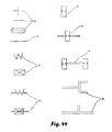
Reference is now made to FIG. 44, presenting symbol legend used for depicting magnetic circuits in the electrical machine. Specifically, the numeral 1 refers to an axis of a electrical machine shaft, 2 to a magnetic conductor, 3 to an electromagnet coil, 4 to an electromagnet coil provided with a core, 5 to a permanent magnet, 6 to a permanent magnet provided with polar extensions, 7 to permanent magnets interconnected by a magnetic conductor, 8 to a magnetic conductor provided with polar extensions.
Reference is now made to FIGS. 45 to 104, presenting diagrams of magnetic circuits in the electrical machine 100 and spatial arrangements of the magnetic field sources 153 and 143 of the first and second pluralities, respectively, relative to the shaft axis 130. The magnetic field sources 153 and 143 comprise electromagnets 120 and permanent magnets 110.
Reference is now made to FIGS. 45-49 and 93-104, presenting diagrams of the magnetic circuits in the electrical machine 100, wherein the magnetic field sources are independent of each other.
FIGS. 47 and 48 present diagrams of the magnetic circuits in the electrical machine 100, wherein axes of magnetization 200 of the magnetic field sources 143 and 153 are parallel to the rotor axis 130.
FIGS. 45 and 46 present diagrams of the magnetic circuits in the electrical machine 100, wherein axes of magnetization 200 of the magnetic field sources 143 and 153 are radially directed to the rotor axis 130.
FIGS. 74 and 75 present diagrams of the magnetic, circuits in the electrical machine 100, wherein axes of magnetization 200 of the magnetic field sources 153 are circularly-oriented in a plane which is perpendicular to the rotor axis 130.
FIGS. 45-49 present diagrams of the magnetic circuits in the electrical machine 100, wherein axes of magnetization 200 of the magnetic field sources 143 and 153 are parallel.
FIGS. 50-54 present diagrams of the magnetic circuits in the electrical machine 100, wherein axes of magnetization 200 of the magnetic field sources 143 and 153 are perpendicular.
FIG. 71 present diagrams of the magnetic circuits in the electrical machine 100, wherein axes of magnetization 200 of the magnetic field sources 143 and 153 are parallel and perpendicular, respectively.
FIGS. 45 to 49 present diagrams of the magnetic circuits in the electrical machine 100, wherein the magnetic field sources 143 and are disposed inside the magnetic field sources 153.
FIGS. 58 and 63 present diagrams of the magnetic circuits in the electrical machine 100, wherein the magnetic field sources 153 and are disposed inside the magnetic field sources 143.
FIGS. 46, 48 and 51 present schemes of the magnetic circuits in the electrical machine 100 adapted for use as an electrical motor.
FIGS. 47, 49, 50 and 54 present schemes of the magnetic circuits in the electrical machine 100 adapted for use as an electrical generator.
FIGS. 93 to 104 present schemes of the magnetic circuits in the electrical machine 100, wherein the permanent magnet 110 is provided with the polar extensions 115.
FIGS. 97 to 104 present schemes of the magnetic circuits in the electrical machine 100, wherein the magnetic flux passes through the air gap between the flat surfaces of the magnetic conductors.
FIGS. 93 to 96 present schemes of the magnetic circuits in the electrical machine 100, wherein the magnetic flux passes through the air gap between the three-dimensionally configured surfaces of the magnetic conductors.
FIGS. 75, 77, and 82-85 present schemes of the magnetic circuits in the electrical machine 100, wherein the aforesaid circuits are configured as layers.
FIGS. 86 to 89 present schemes of the magnetic circuits in the electrical machine 100, wherein the aforesaid circuits are configured as sections.
FIGS. 91 and 92 present schemes of the magnetic circuits in the electrical machine 100, wherein the aforesaid circuits are configured as layers and sections.
It should be understood that in FIGS. 45-104 in the magnetic circuits of the electrical machine 100, the magnetic sources 143 and 153 comprising the permanent magnets 110 and/or electromagnets 120 presented in FIGS. 9-11. FIGS. 45-92 in the magnetic circuits of the electrical machine 100, one or both poles 112 of the permanent magnet 110 face through gaps 160 the poles 125 of the electromagnets 120. The polar extensions 112, 115
Figure US09502951-20161122-P00003
125 are presented in FIGS. 28-33
Figure US09502951-20161122-P00004
95-104.
In accordance with the current invention, an electrical machine comprising a stator and a rotor rotatable relative to the stator with an air gap therebetween is disclosed. The stator is provided with a first plurality of sources of magnetic field which is equally spaced in a circumferential configuration over the stator. The rotor is provided with a second plurality of sources of magnetic field which is equally spaced in a circumferential configuration over the rotor. The magnetic sources of at least one plurality are electromagnets. Each electromagnet comprises at least one magnet coil resting on a magnet circuit. The circuit comprises at least one member made of a material selected from the group consisting of a magnetically isotropic material, a magnetically anisotropic material and any combination thereof.
The elements of magnetic conductor made of magnetically anisotropic material are configured so that the magnetic flux of magnetic sources goes along the direction of easy magnetization. The material is characterized electric resistance more than about 106 Ohm·m, coercitive force less than about 100 A·m−1, relative magnetic permeability more than about 3000 and saturation magnetic induction more than about 0.6 Tl at frequency lower than about 10000 Hz.
In accordance with one embodiment of the current invention, the circuit members made of a magnetically anisotropic material are configured so that a magnet flux created by the magnetic source is conducted along a direction of easy magnetization.
In accordance with another embodiment of the current invention, the magnetic sources of the first plurality are electromagnets spaced over the stator. The magnetic sources of the second plurality are permanent magnets heteropolarly spaced over the rotor.
In accordance with a further embodiment of the current invention, the magnetic sources of the first plurality are permanent magnets heteropolarly spaced over the stator. The magnetic sources of the second plurality are electric magnets spaced over the rotor provided with coils connected with a commutator by means of brushes.
In accordance with a further embodiment of the current invention, the magnetic sources of the first and second pluralities are electric magnets. The electric magnets of the second plurality are provided with coils connected with a commutator by means of brushes.
In accordance with a further embodiment of the current invention, at least one plurality of the magnetic field sources is magnetically independent between each other.
In accordance with a further embodiment of the current invention, an orientation of an axis of the coil of each electric magnet of the first plurality is selected from the group consisting of: an orientation sufficiently parallel to a rotation axis of the rotor, an orientation, sufficiently radially directed relative to the rotor, a circumferential orientation in a plane sufficiently perpendicular the rotation axis of the rotor and any combination thereof.
In accordance with a further embodiment of the current invention, magnetic axes of at least a part of the magnetic sources of the first and second pluralities are parallel each other.
In accordance with a further embodiment of the current invention, magnetic axes of at least a part of the magnetic sources of the first and second pluralities are perpendicular each other.
In accordance with a further embodiment of the current invention, the magnetic circuits of the magnetic sources of the second plurality are disposed inside the magnetic sources of the first plurality.
In accordance with a further embodiment of the current invention, the magnetic circuits of the magnetic sources of the first plurality are disposed inside the magnetic sources of the second plurality.
In accordance with a further embodiment of the current invention, a shape of the magnetic circuits of the electric magnet is selected from the group consisting of an I-like shape; a U-like shape; a T-like shape; a C-like shape, X-like shape and any combination thereof.
In accordance with a further embodiment of the current invention, the permanent magnets are provided with extension members magnetically connected thereto; the extension members are adapted for shunting a magnetic flux generated by the electromagnets. The extension members are adapted for preventing the flux from passing though the permanent magnets when the permanent magnets face to neighbouring electromagnets so that transverse size of the extension members is greater than a distance between neighbouring electric magnets. It is experimentally confirmed that, the proposed technical solution provides reduction of cogging torque ripple. Additionally, resistance of the permanent magnets to demagnetization is improved, due to affection of oppositely directed magnetic fields and temperature.
In accordance with a further embodiment of the current invention, the polar extensions are made from a material selected from the group consisting of a magnetically isotropic material, a magnetically anisotropic material and any combination thereof. The polar extensions are configured so that the magnetic flux of magnetic sources goes along the direction of easy magnetization. The material is characterized electric resistance more than about 106 Ohm·m, coercitive force less than about 100 A·m−1, relative magnetic permeability more than about 3000 and saturation magnetic induction more than about 0.6 Tl at frequency lower than about 10000 Hz.
In accordance with a further embodiment of the current invention the extension members are made of the magnetically anisotropic material are configured so that a magnet flux created by the magnetic source is conducted along a direction of easy magnetization.
In accordance with a further embodiment of the current invention, a shape of the magnetic circuits of the source of magnetic field comprising the permanent magnet is selected from the group consisting of an I-like shape; a U-like shape; a T-like shape; a C-like shape, X-like shape and any combination thereof. The proposed technical solutions provide reduction of losses due to hysteresis losses and Foucault currents.
In accordance with a further embodiment of the current invention, the magnetic source extension member of the second plurality is adapted for conducting a magnetic flux which passes through at least one surface of a core of the magnetic sources of the first plurality selected from butt surface and side surface.
In accordance with a further embodiment of the current invention, the magnetic source extension member of the first plurality is adapted for conducting a magnetic flux which passes through at least one surface of a core of the magnetic sources of the second plurality selected from butt surface and side surface. This technical solution provides reduction in magnetic saturation in the polar extensions 115 and 125 and leakage flux.
In accordance with a further embodiment of the current invention, the electrical machine is adapted for using as an electrical motor. The air gap is peripherally located relative to the rotation axis the rotor. This technical solution results in increase in a moment arm, a rotational torque, and a motor output.
In accordance with a further embodiment of the current invention, the electrical machine is adapted for using as an electrical motor of wheel drive of a vehicle. The second plurality of magnetic field sources of the rotor is mechanically connected to the wheel. The first plurality of magnetic field sources of the stator is mechanically connected to a vehicle body.
In accordance with a further embodiment of the current invention, the second plurality of magnetic field sources of the rotor is fastened to a wheel shaft. The first plurality of magnetic field sources of the stator is mechanically connected to a vehicle body.
In accordance with a further embodiment of the current invention, the electrical machine is adapted for using as an electrical generator. The air gap is proximately located relative to the rotation axis the rotor. This technical solution results in increase in a parasite rotational torque which spins down the generator.
In accordance with a further embodiment of the current invention, the first and second pluralities are layered so that layers pertaining to the first and second pluralities are interlayered therebetween.
In accordance with a further embodiment of the current invention, a number of magnetic sources is constant for each layer.
In accordance with a further embodiment of the current invention, a number of magnetic sources is variable for each layer.
In accordance with a further embodiment of the current invention, the number of magnetic sources increases with layer radius.
In accordance with a further embodiment of the current invention, the layers of circumferentially spaced magnetic sources of the first and second pluralities are angularly displaced relative to each other in a successive manner so that an angular displacement φ between each previous and subsequent layer is less than a polar pitch τ.
In accordance with a further embodiment of the current invention, the spaced magnetic sources of second plurality of each previous layer are angularly shifted relative to spaced magnetic sources of second plurality of each subsequent layer for a predetermined angle which is less than polar pitch.
In accordance with a further embodiment of the current invention, the spaced magnetic sources of first plurality of each previous layer are angularly shifted relative to spaced magnetic sources of first plurality of each subsequent layer for a predetermined angle which is less than the polar pitch.
In accordance with a further embodiment of the current invention, the predetermined angle equals to the polar pitch divided by a number of said layers.
In accordance with a further embodiment of the current invention, the electrical machine has a sliced structure. The electrical machine comprises slices spaced along the shaft axis; each slice comprises magnetic sources of the first and second pluralities facing each other.
In accordance with a further embodiment of the current invention, the rotor comprises a plurality of projections carrying the magnetic field sources of the second plurality at both sides thereof.
In accordance with a further embodiment of the current invention, the stator comprises a plurality of projections carrying the magnetic field sources of the first plurality at both sides thereof.
In accordance with a further embodiment of the current invention, a number of magnetic sources spaced along each slice is constant.
In accordance with a further embodiment of the current invention, a number of magnetic sources spaced along each slice is variable.
In accordance with a further embodiment of the current invention, magnetic sources spaced along a succedent slice is angularly displaced relative to magnetic sources spaced along previous slice for an angular distance φ which is less than a polar pitch τ.
In accordance with a further embodiment of the current invention, the spaced magnetic sources of first plurality of each previous section are angularly shifted relative to spaced magnetic sources of first plurality of each subsequent section for a predetermined angle which is less than the polar pitch.
In accordance with a further embodiment of the current invention, the spaced magnetic sources of second plurality of each previous section are angularly shifted relative to spaced magnetic sources of second plurality of each subsequent section for a predetermined angle which is less than the polar pitch.
In accordance with a further embodiment of the current invention, the predetermined angle equals to the polar pitch divided by a number of the sections.
It should be emphasized that angular displacement of the magnetic sources spread over the layers and/or sections through the aforesaid angle results in reduction of cogging torque ripple. The disclosed electrical motor arrangement provides easy starting independently on relative position of the stator and rotor.
In accordance with a further embodiment of the current invention, a method of use of an electrical machine is disclosed. The aforesaid method comprises the steps of
    • (c) providing a electrical machine comprising a stator and a rotor rotatable relative to said stator with an air gap therebetween; the stator provided with a first plurality of sources of magnetic field equally spaced in a circumferential configuration over the stator; the rotor provided with a second plurality of sources of magnetic field equally spaced in a circumferential configuration over the rotor; the magnetic sources of at least one plurality being electromagnets; each electromagnet comprising at least one magnet coil resting on a magnet conductor; and
    • (d) converting electrical energy into rotation of a machine shaft or inversely;
The conductor is provided with at least one member made of a material selected from the group consisting of a magnetically isotropic material, a magnetically anisotropic material and any combination thereof; said isotropic and anisotropic materials are characterized by an electric resistance greater than about 106 Ohm·m, coercitive force less than about 100 A·m−1; relative magnetic permeability greater than about 3000 and saturation magnetic induction greater than about 0.6 Tl at a frequency lower than about 10000 Hz.

Claims (35)

The invention claimed is:
1. An electrical machine, comprising:
a stator; and
a rotor rotatable relative to said stator with a double air gap therebetween;
said stator provided with a first plurality of magnetic sources equally spaced in a circumferential configuration over said stator;
said rotor provided with a second plurality of magnetic sources equally spaced in a circumferential configuration over said rotor; said magnetic sources of at least one plurality being electromagnets, and of the other plurality being permanent magnets, each permanent magnet having its magnetic axis radially disposed;
each electromagnet comprising at least one magnet coil resting on a magnet conductor and being magnetically independent of the other electromagnet, so that for each electromagnet the magnetic flux contour closes, via a corresponding permanent magnet of the rotor, within said electromagnet; and
wherein each magnet conductor includes first and second portions that are radially disposed with respect to each other and a radial-extending bridging portion adjoining the first and second portions, the first and second portions defining a gap therebetween that is configured to receive both poles of the same permanent magnet, such that magnetic flux of each permanent magnet and its corresponding embracing electromagnet, is required to cross each of the double radial air gaps radially only once.
2. The electrical machine according to claim 1, wherein said magnetic sources of said first plurality are electromagnets spaced over the stator; said magnetic sources of said second plurality are permanent magnets heteropolarly spaced over said rotor.
3. The electrical machine according to claim 1, wherein said magnetic sources of said first plurality are permanent magnets heteropolarly spaced over said stator; said magnetic sources of said second plurality are electric magnets spaced over said rotor provided with coils connected with a commutator by means of brushes.
4. The electrical machine according to claim 1, wherein said magnetic sources of said first and second pluralities are electric magnets; said electric magnets of said second plurality are provided with coils connected with a commutator by means of brushes.
5. The electrical machine according to claim 1, wherein at least one plurality of said magnetic field-sources are magnetically independent between each other.
6. The electrical machine according to claim 1, wherein an orientation of an axis of said coil of each electromagnet of said first plurality is selected from the group consisting of: an orientation sufficiently parallel to a rotation axis of said rotor, an orientation, sufficiently radially directed relative to said rotor, a circumferential orientation in a plane sufficiently perpendicular said rotation axis of said rotor and any combination thereof.
7. The electrical machine according to claim 6, wherein magnetic axes of at least a part of said magnetic sources of said first and second pluralities are parallel each other.
8. The electrical machine according to claim 6, wherein magnetic axes of at least a part of said magnetic sources of said first and second pluralities are perpendicular each other.
9. The electrical machine according to claim 1, wherein the first and second portions and the radial-extending bridging portion collectively define a shape of said electromagnet that is a U-like shape or a C-like shape.
10. The electrical machine according to claim 1, wherein said permanent magnets are provided with magnetic source extension members magnetically connected thereto; wherein transverse size of said extension members is greater than a distance between neighboring electromagnets, whereby said extension members are configured for shunting a magnetic flux generated by said electromagnets; and for preventing said flux from passing though said permanent magnets when said permanent magnets face to neighbouring electromagnets.
11. The electrical machine according to claim 10, wherein said extension members comprise at least one member made of a material selected from a group consisting of said magnetically isotropic material, said magnetically anisotropic material and any combination thereof.
12. The electrical machine according to claim 10, wherein said extension members are made of said magnetically anisotropic material are configured so that a magnet flux created by said magnetic source is conducted along a direction of easy magnetization.
13. The electrical machine according to claim 1, wherein said magnetic source comprising said permanent magnet the shape of which is selected from the group consisting of an I-like shape; a U-like shape; a T-like shape; a C-like shape, X-like shape and any combination thereof.
14. The electrical machine according to claim 9, wherein said magnetic source of said second plurality has an extension member configured for conducting a magnetic flux which passes through at least one surface of a core of said magnetic sources of said first plurality selected from butt surface and side surface.
15. The electrical machine according to claim 9, wherein said magnetic source of said first plurality has an extension member adapted for conducting a magnetic flux which passes through at least one surface of a core of said magnetic sources of said second plurality selected from butt surface and side surface.
16. The electrical machine according to claim 1 are configured to be used as an electrical motor, wherein said air gap is peripherally located relative to a rotation axis of said rotor.
17. The electrical machine according to claim 1 are configured to be used as an electrical generator, wherein said air gap is proximately located relative to a rotation axis of said rotor.
18. The electrical machine according to claim 1, wherein said first and second pluralities are layered so that layers pertaining to said first and second pluralities are interlayered therebetween.
19. The electrical machine according to claim 18, wherein a number of magnetic sources is constant for each layer.
20. The electrical machine according to claim 18, wherein a number of magnetic sources is variable for each layer.
21. The electrical machine according to claim 18, wherein said number of magnetic sources increases with layer radius.
22. The electrical machine according to claim 18, wherein said layer of circumferentially spaced magnetic sources of said first and second pluralities are angularly displaced relative to each other in a successive manner so that an angular displacement between each previous and subsequent layer is less than a polar pitch.
23. The electrical machine according to claim 18, wherein said spaced magnetic sources of second plurality of each previous layer are angularly shifted relative to spaced magnetic sources of second plurality of each subsequent layer for a predetermined angle which is less than a polar pitch.
24. The electrical machine according to claim 18, wherein said spaced magnetic sources of first plurality of each previous layer are angularly shifted relative to spaced magnetic sources of first plurality of each subsequent layer for a predetermined angle which is less than a polar pitch.
25. The electrical machine according to claim 23, wherein said predetermined angle equals to said polar pitch divided by a number of said layers.
26. The electrical machine according to claim 1, having a sliced structure; electrical machine comprising slices spaced along said rotation axis; each slice comprises magnetic sources of said first and second pluralities facing each other.
27. The electrical machine according to claim 26, wherein said rotor comprises a plurality of projections carrying said magnetic field sources of said second plurality at both sides thereof.
28. The electrical machine according to claim 26, wherein said stator comprises a plurality of projections carrying said magnetic field sources of said first plurality at both sides thereof.
29. The electrical machine according to claim 26, wherein a number of magnetic sources spaced along each slice is constant.
30. The electrical machine according to claim 26, wherein a number of magnetic sources spaced along each slice is variable.
31. The electrical machine according to claim 26, wherein said magnetic sources of said first and second pluralities spaced along a subsequent slice is angularly displaced relative to magnetic sources spaced along previous slice for an angular distance Φ which is less than a polar pitch.
32. The electrical machine according to claim 31, wherein said magnetic sources of said second pluralities of each previous section are angularly displaced relative to each subsequent section so that an angular displacement between each previous and subsequent section is less than a polar pitch.
33. The electrical machine according to claim 31, wherein said spaced magnetic sources of first plurality of each previous section are angularly shifted relative to spaced magnetic sources of first plurality of each subsequent section for a predetermined angle which is less than said polar pitch.
34. The electrical machine according to claim 32, wherein said predetermined angle equals to said polar pitch divided by a number of said sections.
35. An electrical machine, comprising:
a stator; and
a rotor rotatable relative to said stator with a double air gap therebetween;
said stator provided with a first plurality of magnetic sources equally spaced in a circumferential configuration over said stator;
said rotor provided with a second plurality of magnetic sources equally spaced in a circumferential configuration over said rotor; said magnetic sources of at least one plurality being electromagnets, and of the other plurality being permanent magnets, each permanent magnet having its magnetic axis radially disposed;
each electromagnet comprising at least one magnet coil resting on a magnet conductor and being magnetically independent of the other electromagnet, so that for each electromagnet the magnetic flux contour closes, via a corresponding permanent magnet of the rotor, within said electromagnet; and
wherein each magnet conductor is a unitary body, configured for radially delimiting both poles of the same permanent magnet, such that magnetic flux can pass radially from one side of permanent magnet to an opposite side thereof through the unitary body of the magnet conductor itself.
US13/147,650 2009-02-05 2010-01-05 Electrical machine Active 2031-07-29 US9502951B2 (en)

Priority Applications (1)

Application Number Priority Date Filing Date Title
US13/147,650 US9502951B2 (en) 2009-02-05 2010-01-05 Electrical machine

Applications Claiming Priority (4)

Application Number Priority Date Filing Date Title
US15003709P 2009-02-05 2009-02-05
US23537109P 2009-08-20 2009-08-20
PCT/IL2010/000007 WO2010089734A2 (en) 2009-02-05 2010-01-05 Electrical machine
US13/147,650 US9502951B2 (en) 2009-02-05 2010-01-05 Electrical machine

Related Parent Applications (1)

Application Number Title Priority Date Filing Date
US15003709P Division 2009-02-05 2009-02-05

Publications (2)

Publication Number Publication Date
US20120007458A1 US20120007458A1 (en) 2012-01-12
US9502951B2 true US9502951B2 (en) 2016-11-22

Family

ID=42320760

Family Applications (1)

Application Number Title Priority Date Filing Date
US13/147,650 Active 2031-07-29 US9502951B2 (en) 2009-02-05 2010-01-05 Electrical machine

Country Status (9)

Country Link
US (1) US9502951B2 (en)
EP (2) EP3751704A1 (en)
CN (1) CN102388524B (en)
ES (1) ES2825148T3 (en)
HR (1) HRP20201606T1 (en)
LT (1) LT2394351T (en)
PL (1) PL2394351T3 (en)
SI (1) SI2394351T1 (en)
WO (1) WO2010089734A2 (en)

Cited By (3)

* Cited by examiner, † Cited by third party
Publication number Priority date Publication date Assignee Title
US20180109166A1 (en) * 2016-10-17 2018-04-19 Roul Delroy MARTIN Rotatable electric machines
WO2022058939A1 (en) 2020-09-21 2022-03-24 Evr Motors Ltd. Radial flux electric machine
US11296572B1 (en) 2020-09-21 2022-04-05 Evr Motors Ltd Electric machine with variable cross-sectional area constant perimeter trapezoidal teeth

Families Citing this family (20)

* Cited by examiner, † Cited by third party
Publication number Priority date Publication date Assignee Title
EP3751704A1 (en) 2009-02-05 2020-12-16 Evr Motors Ltd. Electrical machine
JP2013198261A (en) * 2012-03-19 2013-09-30 Denso Corp Exciting apparatus for rotary electric machine
CN109149799A (en) 2012-08-31 2019-01-04 拉彭兰塔理工大学 Motor
US20140210305A1 (en) * 2013-01-25 2014-07-31 Everette Energy, LLC Single phase switched reluctance machine with axially extending stator laminations
WO2014133244A1 (en) * 2013-02-27 2014-09-04 Baek Seong-Ryong Power generation device using magnetic force
US10916999B2 (en) 2013-03-19 2021-02-09 Intellitech Pty Ltd Device and method for using a magnetic clutch in BLDC motors
EP2838180B1 (en) * 2013-08-16 2020-01-15 Siemens Aktiengesellschaft Rotor of a dynamo-electric rotational machine
CN105981262B (en) 2013-09-18 2019-01-11 Evr电动机有限公司 Multipolar dynamo
EP3058639A4 (en) * 2013-10-14 2017-03-01 Ekoard Ltd. Inverse transverse flux machine
CN103595213A (en) * 2013-11-20 2014-02-19 戴珊珊 Alternating-current permanent-magnet switched reluctance drive
CN103560633B (en) * 2013-11-20 2018-09-18 戴珊珊 AC permanent magnet synergistic reluctance motor
US10290598B2 (en) * 2014-08-07 2019-05-14 Intel Corporation Method and apparatus for forming backside die planar devices and saw filter
TWI570816B (en) * 2014-09-26 2017-02-11 矽品精密工業股份有限公司 Package structure and method of manufacture
GB2544720A (en) * 2015-10-15 2017-05-31 Vastech Holdings Ltd Electric motor
CA3031369A1 (en) * 2016-07-20 2018-01-25 Dumitru Bojiuc Variable magnetic monopole field electro-magnet and inductor
WO2018175393A1 (en) 2017-03-20 2018-09-27 Starrotor Corporation High-magnetic-flux discrete stator electrical machine
GB201722054D0 (en) 2017-12-28 2018-02-14 Vastech Holdings Ltd Electric Motor
DE102020005457A1 (en) 2020-09-07 2022-03-10 Daimler Ag Stator for a transverse flux machine
DE102021212186A1 (en) 2021-10-28 2023-05-04 Mahle International Gmbh Transverse flux machine, in particular for a motor vehicle
WO2024026521A1 (en) * 2022-08-02 2024-02-08 Gk Innovation Gmbh Electric motor, vehicle equipped with said electric motor, and method for operating the electric motor

Citations (47)

* Cited by examiner, † Cited by third party
Publication number Priority date Publication date Assignee Title
US3330975A (en) 1964-10-15 1967-07-11 Vega Prec Lab Inc Self-starting synchronous motor
GB1525959A (en) 1974-10-21 1978-09-27 Western Electric Co Magnetic devices including amorphous alloys
US4899074A (en) 1987-10-13 1990-02-06 Magneti Marelli Electrical Limited Permanent magnet rotary dynamo electric machines
US5051641A (en) 1987-02-13 1991-09-24 J. M. Voith Gmbh Transversal flow machine in accumulator arrangement
US5258697A (en) 1991-10-23 1993-11-02 Varelux Motor Corp. Efficient permanent magnet electric motor
US5289072A (en) 1990-11-23 1994-02-22 J. M. Voith Gmbh Electrical machine
WO1995004399A1 (en) 1993-07-31 1995-02-09 Herbert Weh Electrical machine
US5651841A (en) 1994-07-22 1997-07-29 Tdk Corporation Powder magnetic core
US5696419A (en) * 1994-06-13 1997-12-09 Alternative Generation Devices, Inc. High-efficiency electric power generator
US5808392A (en) 1994-04-28 1998-09-15 Kabushiki Kaisha Toshiba Permanent magnet type rotating machine
WO1999060692A2 (en) 1998-05-16 1999-11-25 Enertec Korea Co., Ltd. Magnetic circuit for rotating apparatus
US6097118A (en) 1998-10-30 2000-08-01 University Of Chicago Reluctance apparatus for flywheel energy storage
US6188159B1 (en) 1998-02-12 2001-02-13 Yang-Fung Fan Stator used for dynamo or electromotor
EP1115127A2 (en) 2000-01-06 2001-07-11 Seiko Epson Corporation Magnetic powder and isotropic bonded magnet
WO2002003527A2 (en) 2000-05-10 2002-01-10 S.H.R. Limited Bvi Stators and rotors for rotary electrical machine
WO2002037651A2 (en) 2000-11-06 2002-05-10 Hitachi, Ltd. Linear motor and method of producing the same
US20020125781A1 (en) 2001-03-08 2002-09-12 Bales John E. Brushless electro-mechanical machine
US6492756B1 (en) 2000-04-05 2002-12-10 Wavecrest Laboratories, Llc Rotary electric motor having magnetically isolated stator and rotor groups
WO2003003385A2 (en) 2001-06-26 2003-01-09 Johns Hopkins University Magnetic devices comprising magnetic meta-materials
EP1283276A1 (en) 2001-08-07 2003-02-12 Shin-Etsu Chemical Co., Ltd. Iron alloy strip for voice coil motor magnetic circuits
US6617746B1 (en) 2001-10-01 2003-09-09 Wavecrest Laboratories, Llc Rotary electric motor having axially aligned stator poles and/or rotor poles
US20040207281A1 (en) * 2001-07-09 2004-10-21 Andrej Detela Hybrid synchronous electric machine
US20040251767A1 (en) 2003-06-10 2004-12-16 Chiarenza Kevin J. Axial flux electromotive generator having rotor magnets and shaped core assembly
US20050110365A1 (en) * 2003-09-04 2005-05-26 Shkondin Vasily V. Electric motor
US20050204545A1 (en) 2000-12-18 2005-09-22 Gieras Jacek F Fabricated components of transverse flux electric motors
US20050212381A1 (en) * 2002-12-07 2005-09-29 Gilmour Kenneth S Electrical machine
US20060006745A1 (en) 2004-07-07 2006-01-12 Industrial Design Laboratories Inc. Integrated blower for cooling device
US7081696B2 (en) * 2004-08-12 2006-07-25 Exro Technologies Inc. Polyphasic multi-coil generator
US20060232154A1 (en) * 2003-04-18 2006-10-19 Ultra Motor Company Limited (A Limited Liability Company Incorporated In Uk) Pulsed-inertial electric motor
JP2007129154A (en) 2005-11-07 2007-05-24 Hitachi Powdered Metals Co Ltd Treatment liquid and treatment method of soft magnetism green compact, magnetic powder and soft magnetic material, and motor using the green compact
US20080169720A1 (en) 2005-05-23 2008-07-17 Marko Petek Synchronous Electromechanical Transformer
US20080179982A1 (en) 2007-01-30 2008-07-31 Arvinmeritor Technology, Llc Transverse flux, switched reluctance, traction motor with bobbin wound coil, with integral liquid cooling loop
US7432623B2 (en) 2001-03-08 2008-10-07 Apex Drives Laboratories, Inc. Brushless electromechanical machine
US20080246362A1 (en) 2003-06-12 2008-10-09 Hirzel Andrew D Radial airgap, transverse flux machine
US20090140526A1 (en) 2007-11-29 2009-06-04 General Electric Company Stator and stator tooth modules for electrical machines
US7800275B2 (en) 2007-05-09 2010-09-21 Motor Excellence, Llc Electrical devices using electronmagnetic rotors
US7816830B2 (en) 2007-08-16 2010-10-19 Gary Dickes Permanent magnet alternator with segmented construction
US7851965B2 (en) 2008-11-03 2010-12-14 Motor Excellence, Llc Transverse and/or commutated flux system stator concepts
US7863784B2 (en) 2005-08-15 2011-01-04 Apex Drive Laboratories, Inc Axial flux permanent magnet machines
US7868510B2 (en) 2007-03-30 2011-01-11 Rittenhouse Norman P High-efficiency wheel-motor utilizing molded magnetic flux channels with transverse-flux stator
EP2317633A2 (en) 2009-10-28 2011-05-04 University of Bahrain Transverse Flux Machine
US8040011B2 (en) 2006-03-16 2011-10-18 The University Court Of The University Of Edinburgh Generator and magnetic flux conducting unit
CN102388524A (en) 2009-02-05 2012-03-21 埃利亚胡·罗兹斯克 Electrical machine
US8339009B2 (en) 2007-09-12 2012-12-25 Ngentec Ltd. Magnetic flux conducting unit
US20130113320A1 (en) 2011-11-08 2013-05-09 Electric Torque Machines, Inc. Transverse and/or commutated flux systems having multidirectional laminations
WO2013102444A1 (en) 2012-01-06 2013-07-11 Liu Gang Electromagnetic coupler
US20130214633A1 (en) 2010-07-29 2013-08-22 Feaam Gmbh Electric machine and stator for same

Family Cites Families (3)

* Cited by examiner, † Cited by third party
Publication number Priority date Publication date Assignee Title
GB191030167A (en) * 1910-12-29 1911-08-10 Frederick William Golby Magneto Generator.
US5179307A (en) * 1992-02-24 1993-01-12 The United States Of America As Represented By The Secretary Of The Air Force Direct current brushless motor
US5982070A (en) * 1996-12-27 1999-11-09 Light Engineering Corporation Electric motor or generator having amorphous core pieces being individually accomodated in a dielectric housing

Patent Citations (53)

* Cited by examiner, † Cited by third party
Publication number Priority date Publication date Assignee Title
US3330975A (en) 1964-10-15 1967-07-11 Vega Prec Lab Inc Self-starting synchronous motor
GB1525959A (en) 1974-10-21 1978-09-27 Western Electric Co Magnetic devices including amorphous alloys
US5051641A (en) 1987-02-13 1991-09-24 J. M. Voith Gmbh Transversal flow machine in accumulator arrangement
US4899074A (en) 1987-10-13 1990-02-06 Magneti Marelli Electrical Limited Permanent magnet rotary dynamo electric machines
US5289072A (en) 1990-11-23 1994-02-22 J. M. Voith Gmbh Electrical machine
US5258697A (en) 1991-10-23 1993-11-02 Varelux Motor Corp. Efficient permanent magnet electric motor
WO1995004399A1 (en) 1993-07-31 1995-02-09 Herbert Weh Electrical machine
US5808392A (en) 1994-04-28 1998-09-15 Kabushiki Kaisha Toshiba Permanent magnet type rotating machine
US5696419A (en) * 1994-06-13 1997-12-09 Alternative Generation Devices, Inc. High-efficiency electric power generator
US5651841A (en) 1994-07-22 1997-07-29 Tdk Corporation Powder magnetic core
US6188159B1 (en) 1998-02-12 2001-02-13 Yang-Fung Fan Stator used for dynamo or electromotor
WO1999060692A2 (en) 1998-05-16 1999-11-25 Enertec Korea Co., Ltd. Magnetic circuit for rotating apparatus
US6097118A (en) 1998-10-30 2000-08-01 University Of Chicago Reluctance apparatus for flywheel energy storage
EP1115127A2 (en) 2000-01-06 2001-07-11 Seiko Epson Corporation Magnetic powder and isotropic bonded magnet
US6492756B1 (en) 2000-04-05 2002-12-10 Wavecrest Laboratories, Llc Rotary electric motor having magnetically isolated stator and rotor groups
WO2002003527A2 (en) 2000-05-10 2002-01-10 S.H.R. Limited Bvi Stators and rotors for rotary electrical machine
WO2002037651A2 (en) 2000-11-06 2002-05-10 Hitachi, Ltd. Linear motor and method of producing the same
US20050204545A1 (en) 2000-12-18 2005-09-22 Gieras Jacek F Fabricated components of transverse flux electric motors
US20020125781A1 (en) 2001-03-08 2002-09-12 Bales John E. Brushless electro-mechanical machine
US6552460B2 (en) 2001-03-08 2003-04-22 Motile, Inc. Brushless electro-mechanical machine
US7432623B2 (en) 2001-03-08 2008-10-07 Apex Drives Laboratories, Inc. Brushless electromechanical machine
WO2003003385A2 (en) 2001-06-26 2003-01-09 Johns Hopkins University Magnetic devices comprising magnetic meta-materials
US20040207281A1 (en) * 2001-07-09 2004-10-21 Andrej Detela Hybrid synchronous electric machine
EP1283276A1 (en) 2001-08-07 2003-02-12 Shin-Etsu Chemical Co., Ltd. Iron alloy strip for voice coil motor magnetic circuits
US6617746B1 (en) 2001-10-01 2003-09-09 Wavecrest Laboratories, Llc Rotary electric motor having axially aligned stator poles and/or rotor poles
US20050212381A1 (en) * 2002-12-07 2005-09-29 Gilmour Kenneth S Electrical machine
US20060232154A1 (en) * 2003-04-18 2006-10-19 Ultra Motor Company Limited (A Limited Liability Company Incorporated In Uk) Pulsed-inertial electric motor
US7285889B2 (en) * 2003-04-18 2007-10-23 Ultra Motor Company Limited Pulsed-inertial electric motor
US6841916B2 (en) 2003-06-10 2005-01-11 Kevin J. Chiarenza Axial flux electromotive generator having rotor magnets and shaped core assembly
US20040251767A1 (en) 2003-06-10 2004-12-16 Chiarenza Kevin J. Axial flux electromotive generator having rotor magnets and shaped core assembly
US20080246362A1 (en) 2003-06-12 2008-10-09 Hirzel Andrew D Radial airgap, transverse flux machine
US20050110365A1 (en) * 2003-09-04 2005-05-26 Shkondin Vasily V. Electric motor
US7723888B2 (en) * 2004-05-25 2010-05-25 Marko Petek Synchronous electromechanical transformer
US20060006745A1 (en) 2004-07-07 2006-01-12 Industrial Design Laboratories Inc. Integrated blower for cooling device
US7081696B2 (en) * 2004-08-12 2006-07-25 Exro Technologies Inc. Polyphasic multi-coil generator
US7595574B2 (en) * 2004-08-12 2009-09-29 Exro Technologies Inc. Polyphasic multi-coil generator
US20080169720A1 (en) 2005-05-23 2008-07-17 Marko Petek Synchronous Electromechanical Transformer
US7863784B2 (en) 2005-08-15 2011-01-04 Apex Drive Laboratories, Inc Axial flux permanent magnet machines
JP2007129154A (en) 2005-11-07 2007-05-24 Hitachi Powdered Metals Co Ltd Treatment liquid and treatment method of soft magnetism green compact, magnetic powder and soft magnetic material, and motor using the green compact
US8040011B2 (en) 2006-03-16 2011-10-18 The University Court Of The University Of Edinburgh Generator and magnetic flux conducting unit
US20080179982A1 (en) 2007-01-30 2008-07-31 Arvinmeritor Technology, Llc Transverse flux, switched reluctance, traction motor with bobbin wound coil, with integral liquid cooling loop
CN101262159A (en) 2007-01-30 2008-09-10 阿文美驰技术有限责任公司 Transverse flux switched reluctance motor, motor for providing rotary drive and its operation method
US7868510B2 (en) 2007-03-30 2011-01-11 Rittenhouse Norman P High-efficiency wheel-motor utilizing molded magnetic flux channels with transverse-flux stator
US7800275B2 (en) 2007-05-09 2010-09-21 Motor Excellence, Llc Electrical devices using electronmagnetic rotors
US7816830B2 (en) 2007-08-16 2010-10-19 Gary Dickes Permanent magnet alternator with segmented construction
US8339009B2 (en) 2007-09-12 2012-12-25 Ngentec Ltd. Magnetic flux conducting unit
US20090140526A1 (en) 2007-11-29 2009-06-04 General Electric Company Stator and stator tooth modules for electrical machines
US7851965B2 (en) 2008-11-03 2010-12-14 Motor Excellence, Llc Transverse and/or commutated flux system stator concepts
CN102388524A (en) 2009-02-05 2012-03-21 埃利亚胡·罗兹斯克 Electrical machine
EP2317633A2 (en) 2009-10-28 2011-05-04 University of Bahrain Transverse Flux Machine
US20130214633A1 (en) 2010-07-29 2013-08-22 Feaam Gmbh Electric machine and stator for same
US20130113320A1 (en) 2011-11-08 2013-05-09 Electric Torque Machines, Inc. Transverse and/or commutated flux systems having multidirectional laminations
WO2013102444A1 (en) 2012-01-06 2013-07-11 Liu Gang Electromagnetic coupler

Non-Patent Citations (2)

* Cited by examiner, † Cited by third party
Title
International Search Report and Written Opinion dated Nov. 23, 2010 in corresponding International Application No. PCT/IL2010/000007.
Israeli Patent Office, "International Search Report in corresponding International Application No. PCT/IL2014/050837", Jan. 5, 2015, Israel.

Cited By (14)

* Cited by examiner, † Cited by third party
Publication number Priority date Publication date Assignee Title
US20180109166A1 (en) * 2016-10-17 2018-04-19 Roul Delroy MARTIN Rotatable electric machines
US10608509B2 (en) * 2016-10-17 2020-03-31 Roul Delroy MARTIN Rotatable electric machines
WO2022058939A1 (en) 2020-09-21 2022-03-24 Evr Motors Ltd. Radial flux electric machine
US11296572B1 (en) 2020-09-21 2022-04-05 Evr Motors Ltd Electric machine with variable cross-sectional area constant perimeter trapezoidal teeth
US11322994B2 (en) 2020-09-21 2022-05-03 Evr Motors Ltd Electric machine with multi-piece trapezoidal teeth
US11336132B2 (en) 2020-09-21 2022-05-17 Evr Motors Ltd Electric machine with liquid cooled coils and stator core
US11349359B2 (en) 2020-09-21 2022-05-31 Evr Motors Ltd Electric machine with SMC rotor core sandwiched between bandage and magnets
US11355985B2 (en) 2020-09-21 2022-06-07 Evr Motors Ltd Electric machine with stator base as common heat sink
US11374444B2 (en) 2020-09-21 2022-06-28 Evr Motors Ltd Method of forming irregular shaped coils of an electric machine
US11451099B2 (en) 2020-09-21 2022-09-20 Evr Motors Ltd Method of inserting multi-part tooth of an electric machine into a coil
US11489379B2 (en) 2020-09-21 2022-11-01 Evr Motors Ltd Electric machine with SMC stator core
US11489378B2 (en) 2020-09-21 2022-11-01 Evr Motors Ltd Electric machine with core piece of multi-piece teeth extending from an annular ring
US11594920B2 (en) 2020-09-21 2023-02-28 Evr Motors Ltd Electric machine with liquid-cooled stator core
US11831202B2 (en) 2020-09-21 2023-11-28 Evr Motors Ltd Electric machine with multi-part trapezoidal teeth

Also Published As

Publication number Publication date
ES2825148T3 (en) 2021-05-14
WO2010089734A2 (en) 2010-08-12
EP2394351B1 (en) 2020-08-05
EP3751704A1 (en) 2020-12-16
CN102388524A (en) 2012-03-21
PL2394351T3 (en) 2021-05-31
US20120007458A1 (en) 2012-01-12
LT2394351T (en) 2021-01-11
HRP20201606T1 (en) 2021-03-05
EP2394351A2 (en) 2011-12-14
SI2394351T1 (en) 2021-07-30
CN102388524B (en) 2016-10-12
WO2010089734A3 (en) 2011-01-06

Similar Documents

Publication Publication Date Title
US9502951B2 (en) Electrical machine
US7535145B2 (en) Axial air gap-type electric motor
JP4102708B2 (en) Motor using permanent magnet
JP5533879B2 (en) Permanent magnet type rotating electrical machine rotor
JPWO2020017078A1 (en) Rotating electric machine
JP3819211B2 (en) Permanent magnet type reluctance type rotating electrical machine
JP2013132124A (en) Core for field element
JP2017112705A (en) Permanent magnet type rotary electric machine and method for manufacturing the same
CN111030402B (en) Directional silicon steel sheet axial magnetic field motor
JP2012257426A (en) Rotor of rotary electric machine
JP5582149B2 (en) Rotor, rotating electric machine and generator using the same
US10056792B2 (en) Interior permanent magnet electric machine
Shah et al. Comparative analysis of surface mounted and flux focusing type axial flux permanent magnet motor
JP5740250B2 (en) Permanent magnet rotating electric machine
JP5197551B2 (en) Permanent magnet rotating electric machine
JP2011172432A (en) Rotor of embedded magnet synchronous motor
JP5608377B2 (en) Rotating electric machine
JP2015106946A (en) Dynamo-electric machine rotor
US20170201137A1 (en) Utilization of Magnetic Fields in Electric Machines
US11791676B2 (en) Electric motor having rotor assembly with segmented permanent magnet
CN114400850B (en) Parallel brushless hybrid excitation motor based on double magnetic bridges
US10116174B2 (en) Synchronous reluctance electric machine
JP2012235607A (en) Synchronous motor
JP2012235608A (en) Synchronous motor
US20230032576A1 (en) Single sided axial flux electrical machine with additional passive stator

Legal Events

Date Code Title Description
AS Assignment

Owner name: ROZINSKY, ELIYAHU, ISRAEL

Free format text: ASSIGNMENT OF ASSIGNORS INTEREST;ASSIGNORS:ROZINSKY, ELIYAHU;KISLEV, VIKTOR;SHABINSKI, RUSLAN;REEL/FRAME:026973/0291

Effective date: 20110803

AS Assignment

Owner name: EVR MOTORS LTD., ISRAEL

Free format text: ASSIGNMENT OF ASSIGNORS INTEREST;ASSIGNOR:ROZINSKY, ELIYAHU;REEL/FRAME:030386/0394

Effective date: 20120506

STCF Information on status: patent grant

Free format text: PATENTED CASE

MAFP Maintenance fee payment

Free format text: PAYMENT OF MAINTENANCE FEE, 4TH YR, SMALL ENTITY (ORIGINAL EVENT CODE: M2551); ENTITY STATUS OF PATENT OWNER: SMALL ENTITY

Year of fee payment: 4