US9501072B2 - Programmable temperature control system for pools and spas - Google Patents
Programmable temperature control system for pools and spas Download PDFInfo
- Publication number
- US9501072B2 US9501072B2 US11/704,718 US70471807A US9501072B2 US 9501072 B2 US9501072 B2 US 9501072B2 US 70471807 A US70471807 A US 70471807A US 9501072 B2 US9501072 B2 US 9501072B2
- Authority
- US
- United States
- Prior art keywords
- temperature control
- control system
- processor
- pool
- programmable temperature
- Prior art date
- Legal status (The legal status is an assumption and is not a legal conclusion. Google has not performed a legal analysis and makes no representation as to the accuracy of the status listed.)
- Active, expires
Links
Images


Classifications
-
- G—PHYSICS
- G05—CONTROLLING; REGULATING
- G05D—SYSTEMS FOR CONTROLLING OR REGULATING NON-ELECTRIC VARIABLES
- G05D23/00—Control of temperature
- G05D23/19—Control of temperature characterised by the use of electric means
- G05D23/1927—Control of temperature characterised by the use of electric means using a plurality of sensors
- G05D23/193—Control of temperature characterised by the use of electric means using a plurality of sensors sensing the temperaure in different places in thermal relationship with one or more spaces
- G05D23/1931—Control of temperature characterised by the use of electric means using a plurality of sensors sensing the temperaure in different places in thermal relationship with one or more spaces to control the temperature of one space
-
- E—FIXED CONSTRUCTIONS
- E04—BUILDING
- E04H—BUILDINGS OR LIKE STRUCTURES FOR PARTICULAR PURPOSES; SWIMMING OR SPLASH BATHS OR POOLS; MASTS; FENCING; TENTS OR CANOPIES, IN GENERAL
- E04H4/00—Swimming or splash baths or pools
- E04H4/12—Devices or arrangements for circulating water, i.e. devices for removal of polluted water, cleaning baths or for water treatment
- E04H4/129—Systems for heating the water content of swimming pools
-
- G—PHYSICS
- G05—CONTROLLING; REGULATING
- G05D—SYSTEMS FOR CONTROLLING OR REGULATING NON-ELECTRIC VARIABLES
- G05D23/00—Control of temperature
- G05D23/19—Control of temperature characterised by the use of electric means
- G05D23/1902—Control of temperature characterised by the use of electric means characterised by the use of a variable reference value
-
- G—PHYSICS
- G05—CONTROLLING; REGULATING
- G05D—SYSTEMS FOR CONTROLLING OR REGULATING NON-ELECTRIC VARIABLES
- G05D23/00—Control of temperature
- G05D23/19—Control of temperature characterised by the use of electric means
- G05D23/1919—Control of temperature characterised by the use of electric means characterised by the type of controller
- G05D23/1923—Control of temperature characterised by the use of electric means characterised by the type of controller using thermal energy, the cost of which varies in function of time
Definitions
- the present invention relates to temperature control systems, and more particularly, to a programmable temperature control system for pools and spas.
- Various temperature controllers have, in the past, been developed for pools and spas.
- One example is a simple thermostat for controlling the temperature of water in a pool or spa.
- a heater is activated when the water temperature is below a desired value, thereby heating the water.
- the heater is deactivated.
- the heater is then re-activated when the water temperature falls below a predetermined threshold. This cycle is continuously repeated so as to maintain the desired water temperature in the pool or spa.
- Heaters for pools and spas can be powered by numerous energy sources, such as gas, oil, or electricity. Some systems employ solar power. Still others combine solar power with conventional oil, gas, or electric heat sources.
- One such system known in the art is disclosed in U.S. Pat. No. 4,368,549 to Ramay (hereinafter “the Ramay '549 patent”).
- the Ramay '549 patent discloses a swimming pool heating system which uses a solar collector as a primary heating source, supplemented by a heater powered by oil, gas, or electricity.
- the temperature control system disclosed in the Ramay '549 patent automatically adjusts the temperature settings of the supplemental heater to conform to the temperature versus time profile of an optimum solar collector heating system.
- Microprocessor-based swimming pool management systems are known in the art.
- One example of such a system is disclosed in U.S. Pat. No. 6,125,481 to Sicilano (hereinafter, the “Sicilano '481 patent”).
- the Sicilano '481 patent discloses a swimming pool management system that automatically dispenses substances into a pool.
- Other systems allow a user to specify a desired temperature and a desired time at which the temperature is to be provided, and control a heater so that the temperature is provided at the desired time.
- the present invention overcomes the disadvantages and shortcomings of the prior art by providing a programmable temperature control system for pools or spas which allows a user to specify both a desired water temperature and a desired time at which the temperature is to be achieved, and which automatically selects one or more optimum heating sources from a plurality of heating sources.
- the programmable temperature control system includes a microprocessor-based controller connected to a plurality of heater actuators, a plurality of valve actuators, and a plurality of sensors.
- the plurality of sensors includes a water temperature sensor, an ambient temperature sensor, an ambient humidity sensor, an ambient light sensor, and, optionally, a depth level sensor and a flow rate sensor.
- the heater actuators are connected to a plurality of heaters, which could include gas, electric, solar, or other types of heaters.
- the controller includes a user interface (e.g., a keyboard and display) for allowing a user to interact with a stored control program for controlling the water temperature of a pool or spa.
- the stored control program allows the user to operate in a manual mode or a program mode. In manual mode, the user can specify a desired water temperature and a desired heat source, and the system heats the water to the desired temperature. Then, the system operates in a thermostat mode, wherein the water temperature is monitored and the heater is controlled to maintain the water temperature at the desired temperature.
- the user can activate one or more stored temperature control programs.
- the stored temperature control program allows the user to specify a desired water temperature and desired time at which the temperature is to be achieved.
- the stored temperature control program identifies the types of heaters present in the system, and their respective power outputs. Based on measured water temperatures, ambient conditions, the power outputs of the heaters, and, optionally, water flow rates, the stored temperature control program activates an optimum heater from the plurality of heaters so that the desired water temperature is provided at the desired time.
- the system can automatically switch to another heater so as to achieve optimum efficiency, or operate two or more heaters at the same time.
- the stored temperature control program can periodically poll the ambient light sensor and ambient temperature sensor to determine whether the sun is shining brightly and whether the ambient temperature is above a predetermined threshold.
- the controller could activate a solar heater to heat the pool water, thereby increasing efficiency.
- Any desired types of stored temperature control programs could be provided in the controller.
- FIG. 1 is a block diagram of a programmable temperature control system for a pool and/or spa constructed in accordance with an exemplary embodiment of the present invention
- FIG. 2 is a block diagram showing the controller of FIG. 1 in greater detail
- FIG. 3 is a perspective view of a control panel having a display and keyboard for allowing a user to interact with the controller of the present invention
- FIG. 4 is a flow chart showing processing steps of the main control program executed by the controller of FIG. 2 ;
- FIG. 5 is a flow chart showing processing steps of a stored temperature control program in accordance with the present invention.
- FIG. 6 is a flow chart showing, in greater detail, the thermostat mode carried out by the stored temperature control program of FIG. 5 ;
- FIG. 7 is a flow chart showing, in greater detail, a stored temperature control sub-program executed by the control program of FIG. 5 ;
- FIG. 8 is a flow chart showing a procedure for determining pool volume
- FIG. 9 is a flow chart showing a procedure for creating a heat source priority list.
- FIG. 10 is a flow chart showing step 216 of FIG. 8 in greater detail.
- FIG. 1 is a block diagram showing the programmable temperature control system of the present invention, indicated generally at 10 .
- the control system 10 is operable with any pool or spa. As shown in FIG. 1 , the control system 10 is operable to control the temperature of water 14 in a pool 12 .
- the pool 12 can be constructed in accordance with any desired design, and could have any desired shape. Thus, for example, the pool 12 could include dual main drains 16 a , 16 b , a skimmer 18 , a pump 20 , a filter 22 , a plurality of heaters 28 a - 28 c , and return jets 34 a , 34 b .
- the control system 10 includes a plurality of valve actuators 26 a - 26 c for selectively controlling valves 24 a - 24 c , a plurality of heater actuators 30 a - 30 c , a controller 32 , a water temperature sensor 36 , a depth level sensor 38 , an inline temperature sensor 40 , a flow rate sensor 42 , an ambient temperature sensor 44 , an ambient humidity sensor 46 , and an ambient light sensor 48 .
- the numbers and types of the sensors 3648 could be varied without departing from the spirit or scope of the present invention.
- the depth level sensor 38 and the flow rate sensor 42 are optional components.
- the inline temperature sensor 40 could be placed downstream of the filter 22 .
- the heaters 28 a - 28 c and the valves 24 a - 24 c are connected in a parallel configuration, but any other desired combination (i.e., serial configuration) could be provided.
- the heaters 28 a - 28 c can be powered by any suitable energy source, such as electricity, gas, oil, or solar power.
- the controller 32 selectively actuates the valves 24 a - 24 c (using the valve actuators 26 a - 26 c ), as well as the heater actuators 30 a - 30 c , based upon ambient and water conditions so that an optimal one of the heaters 28 a - 28 c is operated to heat the water 14 of the pool 12 .
- the valve actuators 26 a - 26 c could be any commercially-available actuator known in the art, such as a solenoid- or motor-driven valve actuator.
- the aforementioned ambient and water conditions are monitored by the controller 32 using the sensors 36 - 48 .
- the depth level sensor 36 measures the depth of the water 14 in the pool 12 so that the controller 32 can approximate the total volume of water 14 in the pool 12 .
- the water temperature sensor 38 measures the temperature of the water 14 of the pool 12 as a whole.
- the inline temperature sensor 40 can also measure the temperature of the water 14 , and could be positioned between the pump 20 and the filter 22 as an alternative to the water temperature sensor 38 , or in addition thereto.
- the sensor 42 measures the flow rate of the water 14 between the pump 20 and the filter 22 .
- the ambient temperature sensor 44 measures the temperature of the air outside of the pool 12 .
- the ambient humidity sensor 46 measures the humidity of the air outside of the pool 12 .
- the ambient light sensor 48 which could be a CdS photocell or any other suitable light sensor, detects the presence and intensity of sunlight, which is used by the controller 32 to determine the heating capacity of a solar heater in the event that such a heater is provided as one of the heaters 28 a - 28 c . Further, the ambient light sensor 48 could be a “black body” sensor, wherein a standard temperature sensor is positioned within a black housing. It has been found that such an arrangement provides increased sensitivity to heat generated by sunlight.
- the heater actuators 30 a - 30 c include circuitry for actuating the heaters 28 a - 28 c , and can also include temperature sensors for measuring the temperature of heated water exiting from the heaters 28 a - 28 c.
- the water 14 is pumped by the pump 20 from the pool 12 via the main drains 16 a , 16 b and the skimmer 18 .
- the water 14 passes through the filter 22 , which could be any suitable commercial or residential pool filter known in the art, to the valves 24 a - 24 c .
- the controller 32 operates one of the valves 24 a - 24 c via a corresponding one of the valve actuators 26 a - 26 c , and activates one or more of the heaters 28 a - 28 c using one of the heater actuators 30 a - 30 c for heating the pool water 14 . It should be noted that two or more of the heaters 28 a - 28 c could be activated simultaneously, if desired.
- the choice of heaters 28 a - 28 c is based on measurements obtained from the sensors 36 - 48 , as well as thermostats in the heater actuators 30 a - 30 c , if provided.
- the heated water 14 flows through return lines to output jets 34 a , 34 b , which return the heated water to the pool 12 .
- FIG. 2 is a block diagram showing the components of the controller 32 of FIG. 1 in greater detail.
- the components of the controller 32 include a power supply 50 , a clock 52 , a processor or central processing unit (CPU) 54 , memory 56 , a display 58 , a keyboard 60 , input/output (I/O) bus circuitry 62 , an actuator interface 64 , an analog-to-digital (A/D) converter 66 , a multiplexer (MUX) 68 , a sensor interface 70 , an external memory interface 74 , and an expansion bus 76 .
- the power supply 50 can include one or more AC-to-DC converters for supplying various voltage levels to the components of the controller 32 .
- the power supply 50 can also include a ground fault circuit interrupter (GFCI) to protect against ground faults.
- the clock 52 can be a battery-backed, real time clock or a zero-crossing detector which derives clock pulses from the AC power line.
- Processor 54 can reside within an embedded system having an external standard bus system.
- the bus system such as STD, VME, or any other bus type, can accept several types of expansion cards via the expansion bus 76 .
- the processor 54 could be the PIC 18F2620 microprocessor manufactured by Microchip, Inc.
- the processor 54 could be programmed in any suitable high or low level language (e.g., assembler language), and it could also run any suitable operating system.
- the memory 56 can include random access memory, read-only memory, hard disk, FLASH memory, or any other suitable memory circuit. Non-volatile memory for the system could also be provided in the memory 56 , and could be expanded as desired using the external memory interface 74 .
- the memory 56 (or external memory plugged into the external memory interface 74 ) stores the control logic executed by the present invention, as well as data gathered from the sensors 36 - 48 and control signals for actuators 26 a - 26 c and the heater interfaces 30 a - 30 c (and, optionally, temperature readings provided by each of the heater interfaces 30 a - 30 c ).
- the control logic of the present invention could be written in any suitable high or low level programming language, and stored as executable object code in the memory 56 .
- the keyboard 60 can include push buttons or a flat panel membrane for allowing a user to interact with the controller 32 of the present invention.
- the keyboard 60 acts as an array of on/off switches, which the processor 54 receives as interrupts. These quantities can be displayed on the display 58 , which can be a vacuum-fluorescent tube, an electroluminescent display, LCD display, etc.
- the keyboard 60 and display 58 could be replaced with a single touch-sensitive display.
- Electrical wiring interfaces 82 a , 82 b connect the keyboard 60 and the display 58 to the controller 32 .
- the keyboard 60 and the display 58 can reside in the vicinity of the pool 12 , or at a remote location, such as within a dwelling.
- the processor 54 includes a number of general purpose, digital I/O control lines which can drive outputs or receive inputs from other devices via the I/O bus circuitry 62 .
- the I/O bus circuitry 62 could also provide a path to the processor 54 for receiving data and interrupts from a GFCI within the power supply 50 when a ground fault is detected, as well as data from the clock 52 and data entered at the keyboard 60 .
- the processor 54 utilizes the I/O bus circuitry 62 to drive the display 58 .
- the processor 54 can receive measurements from the heater actuators 30 a - 30 c and the sensors 36 - 48 via the sensor interface 70 , the analog-to-digital (A/D) converter 66 , and the multiplexer 68 .
- A/D analog-to-digital
- the processor 54 can control one or more of the valve actuators 26 a - 26 c (e.g., to operate one or more of the valves 24 a - 24 c of FIG. 1 ) and one or more of the heater actuators 30 a - 30 c (e.g., to activate one or more of the heaters 28 a - 28 c of FIG. 1 ) using the actuator interface 64 and the I/O bus circuitry 62 .
- the controller 32 can be electrically isolated from the valves 24 a - 24 c and the rest of the pool 12 via isolation circuitry within the actuator interface 64 , which may be implemented, for example, using opto-isolators, solenoids, transformers, etc.
- a flow chart is shown illustrating the main control program 100 of the present invention, which is executed by the processor 54 of FIG. 2 upon application of power to the controller 32 .
- System hardware is initialized at step 102 .
- the registers of the controller are initialized for use. This could be accomplished by setting all of the registers of the controller 32 to pre-defined values.
- a loop timer is also initialized for controlling overall program flow.
- step 106 a determination is made as to whether the loop timer has expired. If a negative decision is made, step 106 is re-invoked.
- step 108 is invoked, wherein the loop timer is re-loaded.
- the circuitry of the controller is synchronized to the frequency of the alternating current (AC) power supply connected to the controller. Among other functions, this allows the controller 32 to synchronously read the sensors and update the relays, actuators, and other devices connected to the controller 32 .
- AC alternating current
- the controller updates all sensors connected to the controller 32 .
- the controller 32 can poll each sensor to determine the types of sensors connected to the sensor interface 70 , as well as the operational status of each sensor (e.g., operational, failure mode, etc.).
- the controller 32 updates all relays and actuators connected thereto.
- the controller 32 checks for user input (such as user input or “keypresses” using the keyboard 60 of FIG. 2 ).
- the controller's memory is updated with the current day and time information stored in the controller's clock (e.g., a real-time clock).
- all timers and clocks (“timeclocks”) utilized by the controller are then updated.
- step 122 the controller 32 acts on commands or information entered by a user. For example, in this step, the user can enter or change date and time information.
- step 124 the controller 32 executes a specialized control program loaded into the memory of the controller 32 , such as the stored temperature control program of the present invention which will be discussed hereinbelow.
- step 126 if an automated pool chlorinator is connected to the controller 32 , it is updated for operation and control by the controller 32 .
- step 128 any errors detected by the controller 32 are processed, including, but not limited to, malfunctioning sensors or actuators connected to the controller 32 .
- the controller 32 can disable a malfunctioning sensor or actuator, display an error code, or undertake any other preprogrammed action.
- non-volatile memory of the controller is updated, if applicable.
- any wired or wireless devices in communication with the controller 32 including but not limited to, handheld controllers, remote control panels connected to the controller 32 (such as inside of a dwelling), or other devices, are updated for use and control. Processing then returns to step 106 .
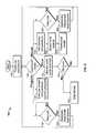
- a flow chart is provided showing processing steps of the stored temperature control program of the present invention, indicated generally at 140 .
- the stored temperature control program 140 could be executed at step 124 of the main control program 100 of FIG. 4 .
- the stored temperature control program 140 allows for both manual and program control of one or more heaters to heat pool or spa water to a desired temperature by a desired time.
- the processor 54 loads the stored temperature control program 140 from the memory 56 and begins executing a power-up procedure at step 142 .
- the power-up procedure 142 which will be discussed in more detail hereinbelow with reference to FIG.
- step 144 is invoked, wherein the processor 54 retrieves a flag from the memory 56 which indicates whether the controller 32 is to operate in manual mode or program mode, and whether an error condition is present. This flag is set either during the power-up procedure in step 142 , or by the user when the user presses one of the keys on the keyboard 60 to select an operating mode, which may cause an interrupt to be generated.
- the controller 32 could be programmed to operate without generating interrupts.
- step 144 the processor 54 determines that the controller 32 is to run in program mode
- step 146 the processor 54 executes a stored temperature control sub-program which resides in the memory 56 .
- This stored temperature control sub-program will be described hereinbelow with reference to FIG. 8 .
- steps 148 - 150 Operating in parallel is a process or task, illustrated in steps 148 - 150 , which listens for interrupts (for example, from the keyboard 60 ). If the processor 54 receives an interrupt at step 148 , then the processor 54 could, if necessary or desirable, deactivate any currently active heat sources (e.g., one of the heaters 28 a - 28 c of FIG. 1 ) at step 150 and return to step 144 .
- any currently active heat sources e.g., one of the heaters 28 a - 28 c of FIG. 1
- step 152 an error code is displayed to the user on the display 58 .
- step 154 the processor 54 attempts to recover from the error condition, and determines whether the error condition has been corrected. For example, the processor 54 could poll a device experiencing an error (either in a single poll or in a series of polls over a period of time) to ascertain whether the device has returned back to an operational state. If, at step 154 , the processor 54 determines that the system is able to recover from the error condition, the processor 54 returns to step 144 for further processing.
- the processor 54 determines that the system is not able to recover from the error condition, the processor 54 enters a safe mode at step 156 wherein any currently active heat source (e.g., one of the heaters 28 a - 28 c of FIG. 1 ) is deactivated.
- any currently active heat source e.g., one of the heaters 28 a - 28 c of FIG. 1
- the processor 54 determines that the controller 32 is to run in manual mode, then at step 158 , the processor 54 prompts the user via the display 58 to enter a desired temperature to which to heat the pool. After the user enters the desired temperature at the keyboard 60 , the desired temperature is stored by the processor 54 in the memory 56 . Then, at step 160 , the processor 54 prompts the user via the display 58 to enter a desired heat source. After the user enters the desired heat source at the keyboard 60 , the desired heat source is stored by the processor 54 in the memory 56 . At step 162 , the processor 54 goes into thermostat mode, to be described hereinbelow with reference to FIG. 7 .
- steps 164 - 166 Operating in parallel is a process or task, illustrated in steps 164 - 166 , which listens for interrupts (for example, from the keyboard 60 ). If the processor receives an interrupt at step 164 , then the processor 54 could, if necessary or desirable, deactivate any currently active heat source (e.g., one of the heaters 28 a - 28 c of FIG. 1 ) at step 166 and return to step 144 .
- any currently active heat source e.g., one of the heaters 28 a - 28 c of FIG. 1
- the total volume of water in the pool 12 is determined at step 168 .
- the total volume of water can be determined automatically as described hereinbelow with reference to FIG. 9 , or it can be entered by the user.
- the processor 54 polls the sensor interface 70 via the multiplexer 68 and the I/O bus circuitry 62 to determined the numbers and the types of sensors present, and stores this information in the memory 56 .
- the processor 54 polls for the presence of a battery-backed clock (i.e., clock 52 ).
- step 174 the processor 54 determines whether the clock 52 is running properly. If not, then step 176 is invoked, wherein an error condition is flagged and the processor 54 then goes into error mode, and notifies the user of the error condition via the display 58 .
- the processor 54 could also spawn a process or task to monitor proper functioning of the clock 52 , which process or task could run in the background. If the clock 52 is running properly, then the current time and date are retrieved by the processor 54 from the clock 52 , and this data is stored in the memory 56 .
- step 178 is invoked, wherein the processor 54 prompts the user at the display 58 to enter the current time.
- the processor 54 prompts the user at the display 58 to enter the current date.
- the processor 54 stores the current time and date in the memory 56 .
- the power-up procedure 142 could be substituted with one or more of the initialization procedures disclosed in connection with the main control program 100 of FIG. 4 without departing from the spirit of scope of the present invention.
- the processor 54 takes a measurement in step 190 of the temperature of the water 14 of the pool 12 .
- the processor 54 activates a desired heat source (i.e., one of the heaters 28 a - 28 c ).
- the processor 54 delays a predetermined amount of time before returning to take another water temperature measurement at step 190 .
- the delay could be pre-set by the manufacturer, or specified by the user.
- the processor 54 determines that the water temperature of the pool is equal to or greater than the desired temperature, then at step 198 , the processor 54 deactivates the desired heat source. At step 200 , the processor 54 delays a predetermined amount of time before taking a water temperature measurement at step 202 . At step 204 , the processor 54 then calculates the difference ( ⁇ T) between the desired temperature and the present pool water temperature. At step 206 , if the processor 54 determines that the absolute value of ⁇ T is greater than a predetermined value (i.e., a maximum permissible temperature deviation, which can be pre-set or specified by the user), then the processor 54 , at step 194 , reactivates the desired heating source. Otherwise, the program returns to step 200 .
- a predetermined value i.e., a maximum permissible temperature deviation, which can be pre-set or specified by the user
- the processor 54 monitors pool temperature by selecting one or more of the output lines associated with the I/O bus circuitry 62 which, in turn, selects an address on address lines (not shown) of the multiplexer 68 .
- the address corresponds to selecting the analog output voltage of the temperature sensors 38 or 40 , both of which measure the water temperature of the pool.
- the analog output voltage of the sensor 38 or 40 is impressed upon the inputs of the A/D converter 66 via the multiplexer 68 and the sensor interface 70 .
- the A/D converter 66 converts the voltage to a digital bit stream which travels through the I/O bus circuitry 62 to the processor 54 .
- the processor 54 compares this temperature to the desired temperature stored in the memory 56 .
- the processor 54 To activate a desired heat source, the processor 54 enables one of the valve actuators 30 a - 30 c via one of the I/O lines of the I/O bus circuitry 62 . This operates one of the valves 24 a - 24 c which permits cool water 14 from the pool 12 to flow through the selected one of the heaters 28 a - 28 c to provide hot water to the pool 12 .
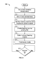
- the desired temperature of water in the pool 12 is determined in step 210 . If the user has previously entered the desired temperature, and no change in temperature is desired, then the processor 54 retrieves the desired temperature from the memory 56 . If the user wishes to change the desired temperature, or the desired temperature has not been previously entered, then the processor 54 prompts the user at the display 58 for the desired temperature. After receiving the desired temperature from the user via the keyboard 60 , the processor 54 stores the desired temperature in the memory 56 . At step 212 , the desired time at which the desired temperature is to be provided is determined.
- the processor 54 retrieves the desired time from the memory 56 . If the user wishes to change the desired time, or the desired time has not been previously entered, then the processor 54 prompts the user at the display 58 for the desired time. After receiving the desired time from the user via the keyboard 60 , then the processor 58 stores the desired time in the memory 56 .
- the processor 54 identifies the numbers and types of heat sources present (e.g., heaters 28 a - 28 c ), and determines the respective power outputs of each identified heat source.
- the processor 54 polls the heater interfaces 30 a - 30 c via the I/O bus hardware 62 , and then receives identification, model type, and power output from the heater interfaces 30 a - 30 c over the I/O bus hardware 62 .
- the processor 54 can determine the presence of each of the heater interfaces 30 a - 30 c , and retrieve the model number and power output of each heat source from the memory 56 .
- the data for each heater stored in the memory 56 can be preprogrammed at the factory, or it can be entered by the user during the power-up procedure 142 (see FIG. 5 ).
- the processor 54 reads the current power output of the ambient light sensor 48 , which is indicative of the power output of the entire solar array, and the processor 54 then makes a calculation of estimated power output of the solar array.
- the processor 54 calculates the current pool water volume, to be described hereinafter with reference to FIG. 8 .
- the processor 54 Based on current pool temperature, the ambient air temperature, the power output of each of the heating sources which are present, and, optionally, the water flow rate, the processor 54 generates in step 216 a heating source priority list, which will be described hereinbelow in greater detail with reference to FIG. 9 .
- the heating source priority list can determine the most energy efficient and/or fastest heating source at the present time for heating the pool 12 up to the desired temperature by the desired time.
- the processor 54 selects the optimal heating source from the priority list generated at step 216 .
- the processor 54 then enters thermostat mode at step 220 as previously described with reference to FIG. 7 .
- the processor 54 updates the heating source priority list. Since the parameters used to generate the heating source priority list, such as a change in power output of the ambient light sensor 48 , may have changed, the processor 54 returns to step 164 to recalculate the heating source priority list.
- step 168 of FIG. 6 is a flow chart showing step 168 of FIG. 6 in greater detail
- the processor 54 takes a depth measurement of the pool water 14 at step 232 by taking a reading of depth level sensor 36 via the sensor interface 70 , the multiplexer 68 , the A/D converter 66 , and the I/O bus hardware 62 . The processor 54 then recalls the pool area from the memory 56 at step 234 .
- This pool area can be factory programmed, or entered by the user during the start-up procedure 142 (see FIG. 5 ).
- the depth measurement determined at step 232 is multiplied by the pool area to obtain the current pool volume.
- the controller of the present invention could be programmed to include a volume of water corresponding to a pool or spa, or the user could be prompted to enter such information into the controller.
- Other attributes, such as the surface area of water in the pool or spa could be pre-programmed or entered by the user.
- FIG. 10 which is a flow chart showing step 216 of FIG. 8 in greater detail, as well as to FIGS. 1 and 2 , the time it would take for each heat source present to heat the current volume of pool water to the desired temperature is calculated at step 240 .
- the current pool temperature must be determined from a measurement from the temperature sensors 38 or 40 .
- measurements from the other sensors 42 and 44 - 48 , and, optionally, temperature sensors within the heater interfaces 30 a - 30 c can be obtained by the processor 54 .
- the controller 32 of the present invention can calculate the approximate time it will take for each of the heaters 28 a - 28 c to reach the desired temperature using known equations and stored information about each of the heaters 28 a - 28 c connected to the controller, which could be preprogrammed by the manufacturer. For example, the controller 32 could prompt the user to specify the types of heating sources (i.e., heaters 28 a - 28 c ) that are present, and could then retrieve from memory power outputs (e.g., in BTU's) associated with the specified heating sources. Then, based upon the volume of the pool and the associated power outputs of the heating sources, the controller 32 can automatically calculate the time it will take each heating source to reach the desired temperature using known temperature calculations.
- the types of heating sources i.e., heaters 28 a - 28 c
- memory power outputs e.g., in BTU's
- those sources which can heat the pool to the desired temperature by the desired time are determined and stored in the memory 56 along with the energy efficiency of each heat source.
- these sources are arranged in a list in order of decreasing energy efficiency and/or increasing heating time. As discussed earlier with respect to FIG. 7 , once the heating source priority list is generated, an optimal heating source is selected from the list and activated to heat the pool water. The optimal heating source is then monitored using the aforementioned thermostat mode.
- controller 32 could be programmed to select a most optimal heating source, and if such heating source is not capable of achieving a desired temperature at a desired time, the controller 32 could activate one or more additional heating sources so that the desired temperature is provided at the desired time.
- the heaters 28 a - 28 c and the valves 24 a - 24 c can be arranged in a series configuration.
- all but one of the valves 24 a - 24 c is operated in bypass mode so that only the desired one of the heaters 28 a - 28 c is not bypassed.
- the multiple valves 24 a - 24 c of FIG. 1 which are arranged in a parallel configuration, can be replaced by a single multi-way valve.
- priority can be based on cost efficiency, e.g., according to the costs associated with running each heater for specified periods of time.
- the heaters 28 a - 28 c can be ranked in terms of speed (i.e., the minimum time it would take a given one of the heaters 28 a - 28 c to heat the pool 12 to the desired temperature).
- the time to heat the pool can be determined with fewer sensors if estimates of parameters are used. For example, flow rate, hot water temperature, and pool volume can be replaced by factory programmed values, or parameters entered by the user during the power-up procedure 142 (see FIG. 5 ) which can be determined from the literature packaged with the equipment.
- temperature sensors can be placed at several locations and depths in the pool 12 and the average temperature of all the temperature sensors can be taken as representing the temperature of the water 14 of the pool 12 .
- Other types of sensors can be included for measuring quantities not directly related to determining a heating method, such as sensors which measure the pH of the water 12 , and a pressure sensor for measuring the water pressure associated with the filter 22 to detect a reduction of fluid flow through the filter 22 due to sedimentation, etc.
- the controller 32 could be programmed to determine if a brown-out condition (e.g., a decrease in the AC voltage level being supplied to the controller 32 ) occurs, as well as to prevent the pump 20 or an electric heat source from being used if such a condition is detected.
- the controller 32 could also include logic for controlling a variable speed pump 20 and automatically adjusting the speed of the pump 20 based on operating conditions.
- the controller 32 could allow the user to input time ranges and corresponding costs for particular energy types, or periodically programmed (locally through software updates, or remotely through a data link connecting to the controller 32 to a utility company) with such information. For example, the controller 32 could allow the user to enter a first cost for electricity during peak hours (e.g.
- the controller 32 could include a wireless or power line carrier (PLC) receiver for receiving signals representing energy costs which are transmitted by a local electric company. In such circumstances, the controller 32 could supplement active heat sources with an electric heat source during non-peak hours.
- PLC power line carrier
- the controller 32 could also include a receiver for receiving power control commands from a utility company to adjust power consumption on demand. For example, the user may get a more favorable rate for electricity if the local electric company is permitted to periodically adjust electrical energy consumption.
- the controller 32 could include an actuator for controlling an automatic pool covering device.
- the controller 32 could be programmed to ensure that the pool is automatically covered at predetermined times or when the ambient temperature reaches a predetermined threshold to minimize heat loss due to evaporation.
- the controller 32 could be connected to an actuator for controlling a water feature in a pool or spa, such as a fountain or aerator, and programmed to control such devices at desired times.
- a single controller of the present invention could be programmed to control the temperatures of multiple bodies of water, and associated equipment (such as sensors and actuators, etc.) could be interconnected with the controller for operation with such multiple bodies of water.
- a single controller could be implemented to control temperatures of both a pool and a spa.
- the user can specify desired temperatures and desired times for achieving such temperatures for both the pool and the spa, and the system of the present invention will achieve such goals using one or more optimal heat sources.
- the controller can selectively direct water flow from one or more heat sources to either (or both) of the pool and the spa, so as to achieve optimal heating for both bodies of water.
- the controller of the present invention could be programmed to allow a user to override (e.g., temporarily stop) an executing temperature control program, and then resume execution of such program.
- the temperature control program could include the ability to re-assess environmental conditions (such as water temperature, ambient temperature, ambient humidity, etc.) and select an optimal heat source based on assessed conditions after execution of the control program has been resumed. Additionally, the controller could re-assess environmental conditions and select an optimal heat source based upon the remaining time to heat the pool water to the desired temperature at the desired time, after resumption of the temperature control program.
Abstract
Description
Claims (45)
Priority Applications (3)
| Application Number | Priority Date | Filing Date | Title |
|---|---|---|---|
| US11/704,718 US9501072B2 (en) | 2006-02-09 | 2007-02-09 | Programmable temperature control system for pools and spas |
| US15/359,112 US11256274B2 (en) | 2006-02-09 | 2016-11-22 | Programmable temperature control system for pools and spas |
| US17/677,800 US20220179436A1 (en) | 2006-02-09 | 2022-02-22 | Programmable Temperature Control System For Pools And Spas |
Applications Claiming Priority (3)
| Application Number | Priority Date | Filing Date | Title |
|---|---|---|---|
| US77165606P | 2006-02-09 | 2006-02-09 | |
| US77176206P | 2006-02-09 | 2006-02-09 | |
| US11/704,718 US9501072B2 (en) | 2006-02-09 | 2007-02-09 | Programmable temperature control system for pools and spas |
Related Child Applications (1)
| Application Number | Title | Priority Date | Filing Date |
|---|---|---|---|
| US15/359,112 Division US11256274B2 (en) | 2006-02-09 | 2016-11-22 | Programmable temperature control system for pools and spas |
Publications (2)
| Publication Number | Publication Date |
|---|---|
| US20070244576A1 US20070244576A1 (en) | 2007-10-18 |
| US9501072B2 true US9501072B2 (en) | 2016-11-22 |
Family
ID=38345841
Family Applications (4)
| Application Number | Title | Priority Date | Filing Date |
|---|---|---|---|
| US11/704,718 Active 2028-08-27 US9501072B2 (en) | 2006-02-09 | 2007-02-09 | Programmable temperature control system for pools and spas |
| US11/704,717 Abandoned US20070233420A1 (en) | 2006-02-09 | 2007-02-09 | Programmable aerator cooling system |
| US15/359,112 Active 2028-12-03 US11256274B2 (en) | 2006-02-09 | 2016-11-22 | Programmable temperature control system for pools and spas |
| US17/677,800 Abandoned US20220179436A1 (en) | 2006-02-09 | 2022-02-22 | Programmable Temperature Control System For Pools And Spas |
Family Applications After (3)
| Application Number | Title | Priority Date | Filing Date |
|---|---|---|---|
| US11/704,717 Abandoned US20070233420A1 (en) | 2006-02-09 | 2007-02-09 | Programmable aerator cooling system |
| US15/359,112 Active 2028-12-03 US11256274B2 (en) | 2006-02-09 | 2016-11-22 | Programmable temperature control system for pools and spas |
| US17/677,800 Abandoned US20220179436A1 (en) | 2006-02-09 | 2022-02-22 | Programmable Temperature Control System For Pools And Spas |
Country Status (4)
| Country | Link |
|---|---|
| US (4) | US9501072B2 (en) |
| EP (2) | EP1999833B1 (en) |
| ES (1) | ES2548757T3 (en) |
| WO (2) | WO2007095087A2 (en) |
Cited By (8)
| Publication number | Priority date | Publication date | Assignee | Title |
|---|---|---|---|---|
| KR100346344B1 (en) * | 1997-04-25 | 2002-08-01 | 모토로라 인코포레이티드 | Method and apparatus for providing synchronization during transcoder switching in a communication system |
| US20170213451A1 (en) | 2016-01-22 | 2017-07-27 | Hayward Industries, Inc. | Systems and Methods for Providing Network Connectivity and Remote Monitoring, Optimization, and Control of Pool/Spa Equipment |
| US20200319621A1 (en) | 2016-01-22 | 2020-10-08 | Hayward Industries, Inc. | Systems and Methods for Providing Network Connectivity and Remote Monitoring, Optimization, and Control of Pool/Spa Equipment |
| US10976713B2 (en) | 2013-03-15 | 2021-04-13 | Hayward Industries, Inc. | Modular pool/spa control system |
| US11142923B2 (en) * | 2014-06-20 | 2021-10-12 | Pentair Water Pool And Spa, Inc. | Hybrid heater |
| US11256274B2 (en) | 2006-02-09 | 2022-02-22 | Hayward Industries, Inc. | Programmable temperature control system for pools and spas |
| US20220136270A1 (en) * | 2019-08-16 | 2022-05-05 | Rheem Manufacturing Company | Systems And Methods For Managing Bodies Of Water |
| US20220341202A1 (en) * | 2019-09-11 | 2022-10-27 | Hayward Industries, Inc. | Swimming Pool Pressure and Flow Control Pumping and Water Distribution Systems and Methods |
Families Citing this family (32)
| Publication number | Priority date | Publication date | Assignee | Title |
|---|---|---|---|---|
| US8370001B2 (en) * | 2008-02-08 | 2013-02-05 | Chris Love | Pool temperature controller |
| US8014902B2 (en) * | 2008-02-22 | 2011-09-06 | Lawrence Kates | Method and apparatus for energy-efficient temperature-based systems management |
| US7848853B2 (en) * | 2008-05-13 | 2010-12-07 | Solarlogic, Llc | System and method for controlling hydronic systems having multiple sources and multiple loads |
| US20110093099A1 (en) * | 2009-10-16 | 2011-04-21 | Newport Controls | Controller system adapted for spa |
| US20110202150A1 (en) * | 2009-10-16 | 2011-08-18 | Newport Controls | Controller system adapted for SPA |
| US20110284440A1 (en) * | 2010-05-19 | 2011-11-24 | Luiz Filipe De Souza Sisson | Multifunctional equipment for filtering pool water |
| US10024578B1 (en) * | 2010-11-08 | 2018-07-17 | Randy L. Rutkai | Combination fence and solar heater for swimming pools |
| US20120251963A1 (en) * | 2011-03-31 | 2012-10-04 | Siemens Industry, Inc. | Thermostat with integrated carbon monoxide (co) sensor |
| US9718371B2 (en) | 2011-06-30 | 2017-08-01 | International Business Machines Corporation | Recharging of battery electric vehicles on a smart electrical grid system |
| US9885193B2 (en) | 2011-07-29 | 2018-02-06 | Patrick Chen | Systems and methods for controlling chlorinators |
| US10156081B2 (en) | 2011-07-29 | 2018-12-18 | Hayward Industries, Inc. | Chlorinators and replaceable cell cartridges therefor |
| US9958173B1 (en) * | 2011-09-08 | 2018-05-01 | Northwest Renewable Energy Corp. | Solar powered roof ventilation system |
| AU2013200596B2 (en) * | 2012-03-22 | 2013-11-28 | Rheem Australia Pty Limited | A Circulating Hot Water System and or Appliance |
| US10022688B2 (en) * | 2012-05-02 | 2018-07-17 | Keeton Industries | Combination submersible and floating aerator |
| US10492268B2 (en) | 2013-03-13 | 2019-11-26 | Hayward Industries, Inc. | Local feature controller for pool and spa equipment |
| EP2967006A4 (en) * | 2013-03-15 | 2016-12-28 | Pentair Water Pool & Spa Inc | Method for regulating energy consumption in aquaculture systems |
| US9689587B1 (en) * | 2013-04-11 | 2017-06-27 | Sheppard & Associates, Llc | Thermosiphon solar collector and process |
| CN103455065B (en) * | 2013-09-25 | 2015-05-13 | 武汉大学 | Automatic water changing system |
| US20160361974A1 (en) * | 2015-06-10 | 2016-12-15 | Ford Global Technologies, Llc | Electric vehicle heating distribution system and method |
| US9971453B2 (en) | 2016-10-19 | 2018-05-15 | Johnson Controls Technology Company | Touch screen device with user interface mode selection based on humidity |
| AU2018239360C1 (en) | 2017-03-21 | 2023-11-02 | Hayward Industries, Inc. | Systems and methods for sanitizing pool and spa water |
| US10458669B2 (en) | 2017-03-29 | 2019-10-29 | Johnson Controls Technology Company | Thermostat with interactive installation features |
| WO2018191510A1 (en) | 2017-04-14 | 2018-10-18 | Johnson Controls Technology Company | Multi-function thermostat with air quality display |
| USD859618S1 (en) | 2017-09-15 | 2019-09-10 | Pentair Water Pool And Spa, Inc. | Heating apparatus clip |
| CN107797588A (en) * | 2017-09-28 | 2018-03-13 | 安徽省金鸿再生资源科技有限公司 | A kind of cooling tower energy regeneration type hydrologic cycle cooling system |
| US11635236B2 (en) * | 2017-10-13 | 2023-04-25 | Intermatic Incorporated | Optimization sensor and pool heater utilizing same and related methods |
| US11131474B2 (en) | 2018-03-09 | 2021-09-28 | Johnson Controls Tyco IP Holdings LLP | Thermostat with user interface features |
| US20200150633A1 (en) * | 2018-11-12 | 2020-05-14 | Zodiac Pool Systems Llc | Sensor systems principally for swimming pools and spas |
| EP3927917A1 (en) * | 2019-04-18 | 2021-12-29 | Zodiac Pool Systems LLC | Method of creating a desired temperature in swimming pools or spas |
| EP3963410A4 (en) * | 2019-05-03 | 2023-01-11 | Hayward Industries, Inc. | Systems and methods for providing monitoring, optimization, and control of pool/spa equipment using video analytics |
| DE102020216201A1 (en) * | 2020-12-17 | 2022-06-23 | Viessmann Climate Solutions Se | CONTROL DEVICE, SYSTEM AND METHOD FOR CONTROLLING A TEMPERATURE IN A ROOM AND RADIATOR DEVICE |
| US20230127276A1 (en) * | 2021-10-21 | 2023-04-27 | Rheem Manufacturing Company | Heat pump pool water heater systems and methods thereto |
Citations (98)
| Publication number | Priority date | Publication date | Assignee | Title |
|---|---|---|---|---|
| US2498818A (en) | 1947-10-03 | 1950-02-28 | Theodore Lawrence | Evaporative air cooler and conditioner |
| US2509031A (en) | 1946-03-01 | 1950-05-23 | Bockmeyer Eldon | Apparatus for cooling fluids |
| US3086715A (en) | 1960-10-31 | 1963-04-23 | Paul J Mineau | Aerator pump |
| US3320160A (en) | 1965-08-24 | 1967-05-16 | Welles Products Inc | Method and apparatus for aerating a body of liquid |
| US3416729A (en) | 1966-08-12 | 1968-12-17 | Richards Of Rockford Inc | Liquid aerator |
| US3497185A (en) | 1968-11-20 | 1970-02-24 | Sydnor Hydrodynamics Inc | Aerating and cooling apparatus |
| US3515375A (en) | 1968-05-22 | 1970-06-02 | Bird Machine Co | Aeration apparatus |
| US3524629A (en) | 1968-07-29 | 1970-08-18 | Don A Culwell | Apparatus for and method of aerating liquids |
| US3528548A (en) | 1967-04-26 | 1970-09-15 | K & L Electronics Inc | Electrical circuit for temperature control of swimming pool water |
| US3572658A (en) | 1968-01-15 | 1971-03-30 | Richards Of Rockford Inc | Floating aerator |
| US3735926A (en) | 1971-05-27 | 1973-05-29 | Richards Of Rockford Inc | Liquid spray device with fixed and rotatable diffusers |
| US3739986A (en) | 1971-08-17 | 1973-06-19 | Richards Of Rockford Inc | Axial flow liquid aerator |
| US3771724A (en) | 1972-07-19 | 1973-11-13 | Richards Of Rockford Inc | Apparatus and process for spraying liquids |
| US3781925A (en) | 1971-11-26 | 1974-01-01 | G Curtis | Pool water temperature control |
| US3809116A (en) * | 1965-05-18 | 1974-05-07 | Santron Corp | Fluid flow control systems |
| US3823767A (en) | 1972-02-29 | 1974-07-16 | Economic Development Corp | Process for treating water |
| US3837016A (en) | 1973-04-11 | 1974-09-24 | Mms Ltd | Plural temperature level fluid heating system |
| US3926008A (en) | 1974-08-15 | 1975-12-16 | Robert C Webber | Building cooling and pool heating system |
| US3953551A (en) | 1973-01-22 | 1976-04-27 | Dorall Arthur G | Air cooling apparatus |
| US3970069A (en) | 1975-02-24 | 1976-07-20 | John Pickett | Solar heater/cooler assembly |
| US4153955A (en) * | 1976-04-01 | 1979-05-15 | Henry Hinterberger | Solar energy converter |
| US4189791A (en) | 1979-01-05 | 1980-02-26 | Dundas Gifford W | Swimming pool heating and cooling system |
| US4226815A (en) | 1979-11-19 | 1980-10-07 | Cockman Haggie I | Cooling apparatus |
| US4233694A (en) | 1979-01-22 | 1980-11-18 | Jacuzzi Whirlpool Bath, Inc. | Spa construction and isolated controls therefor |
| US4322297A (en) * | 1980-08-18 | 1982-03-30 | Peter Bajka | Controller and control method for a pool system |
| US4350589A (en) | 1980-07-12 | 1982-09-21 | Wsw Stahl- Und Wasserbau Gmbh | Floating jet aerator |
| US4368549A (en) | 1980-12-29 | 1983-01-18 | Teledyne Industries, Inc. | Swimming pool heater temperature control system |
| US4381031A (en) | 1980-10-27 | 1983-04-26 | Whitaker Larry D | Spa-domestic hot water heat exchanger |
| US4385724A (en) | 1981-04-09 | 1983-05-31 | Ramco Manufacturing, Inc. | Apparatus for controlling the water temperature of a spa |
| US4393527A (en) | 1980-12-29 | 1983-07-19 | Teledyne Industries, Inc. | Method of controlling non-solar swimming pool heater |
| US4404697A (en) | 1978-08-14 | 1983-09-20 | Intermatic Incorporated | Remote control system for spas |
| US4409694A (en) | 1982-09-30 | 1983-10-18 | John P. Barrett, Sr. | Electronic control device for liquids |
| US4424438A (en) | 1981-11-05 | 1984-01-03 | Stanmar Technology | Remote actuator system |
| US4467183A (en) | 1980-12-19 | 1984-08-21 | Ricoh Company, Ltd. | Liquid temperature control apparatus comprising initial temperature dependent high power heater drive |
| US4541413A (en) | 1982-07-09 | 1985-09-17 | Compagnie Francaise De Raffinage | Pump and control unit for a solar heating installation for a water tank, and particularly for a swimming pool |
| US4563780A (en) | 1983-06-29 | 1986-01-14 | Pollack Simcha Z | Automated bathroom |
| US4564141A (en) | 1984-11-05 | 1986-01-14 | Doleer Electronics, Inc. | Apparatus and method for domestic hot water control |
| US4593177A (en) | 1984-05-18 | 1986-06-03 | Purex Pool Products, Inc. | Reduced differential, high limit thermostat system |
| US4621613A (en) | 1979-01-25 | 1986-11-11 | Krumhansl Mark U | Pool and spa heating and cooling |
| US4780917A (en) | 1987-01-05 | 1988-11-01 | Hancock James W | Spa construction with integrated spa side and inside control system |
| US4930229A (en) | 1989-02-23 | 1990-06-05 | Sentry Technologies, Inc. | Method and apparatus for aeration of stored grain with proactive cooling |
| US4936506A (en) | 1988-11-14 | 1990-06-26 | Ryan James E | Swimming pool fountain |
| US5184472A (en) | 1991-01-08 | 1993-02-09 | Pierre Guilbault | Add on heat pump swimming pool heater control |
| US5278455A (en) | 1990-10-18 | 1994-01-11 | Teledyne Industries, Inc. | Spa and pool pump and heater control |
| US5361215A (en) | 1987-05-27 | 1994-11-01 | Siege Industries, Inc. | Spa control system |
| US5415221A (en) | 1993-12-09 | 1995-05-16 | Zakryk; John M. | Auto switching swimming pool/spa heater system |
| US5526538A (en) | 1995-05-04 | 1996-06-18 | Hurrican Products Incorporated | Water circulation and heating system for spas |
| US5550753A (en) | 1987-05-27 | 1996-08-27 | Irving C. Siegel | Microcomputer SPA control system |
| US5560210A (en) | 1990-12-31 | 1996-10-01 | Ormat Turbines (1965) Ltd. | Rankine cycle power plant utilizing an organ fluid and method for using the same |
| US5585025A (en) | 1993-09-13 | 1996-12-17 | Softub, Inc. | SPA control circuit |
| US5616239A (en) | 1995-03-10 | 1997-04-01 | Wendell; Kenneth | Swimming pool control system having central processing unit and remote communication |
| US5730861A (en) | 1996-05-06 | 1998-03-24 | Sterghos; Peter M. | Swimming pool control system |
| US5787519A (en) * | 1994-05-31 | 1998-08-04 | Smith; Robert Leslie | Compact swimming pool for restrained swimming |
| US5809796A (en) | 1994-03-15 | 1998-09-22 | Zakryk; John M. | Self regulating pool heater unit |
| US5889684A (en) | 1996-10-18 | 1999-03-30 | Waterlogic International Ltd. | Computer-controlled heated and/or cooled liquid dispenser |
| US5932127A (en) | 1998-01-15 | 1999-08-03 | Maddox; Harold D. | Heater control for spa |
| US5988516A (en) | 1994-04-08 | 1999-11-23 | Sola-Kleen Pty. Ltd. | Solar hot water heating system |
| US5996977A (en) | 1998-07-09 | 1999-12-07 | Burgess; Harry L. | Temperature adjusted water aerator and circulation system |
| US6003164A (en) | 1998-07-31 | 1999-12-21 | Leaders; Homer G. | Pool monitor and controller |
| US6044901A (en) | 1998-07-31 | 2000-04-04 | Basala; Donald C. | Live well temperature management apparatus |
| US6084218A (en) | 1999-05-25 | 2000-07-04 | Itt Manufacturing Enterprises, Inc. | Spa heater temperature control circuit |
| US6081944A (en) | 1998-09-09 | 2000-07-04 | Edwards; Hugh A. | Swimming pool screen enclosure supported water misting and cooling apparatus |
| US6109050A (en) | 1994-03-15 | 2000-08-29 | Zakryk; John M. | Self regulating pool heater unit |
| US6125481A (en) | 1999-03-11 | 2000-10-03 | Sicilano; Edward N. | Swimming pool management system |
| US6145139A (en) | 1998-01-31 | 2000-11-14 | Bonn; Stephen P. | Supplementary water heater system for swimming pools and spa |
| US6190544B1 (en) | 1998-01-30 | 2001-02-20 | Flucon Pumps Limited | Aerator with float chamber and turnable inlet |
| US6253121B1 (en) | 1998-09-03 | 2001-06-26 | Balboa Instruments, Inc. | Control system for bathers with ground continuity and ground fault detection |
| US6282370B1 (en) | 1998-09-03 | 2001-08-28 | Balboa Instruments, Inc. | Control system for bathers |
| US20010047539A1 (en) | 2000-03-16 | 2001-12-06 | Lynn John M | Method and apparatus to either heat or cool a pool |
| US6354573B1 (en) | 2000-09-25 | 2002-03-12 | Jorge A. Morando | Swimming pool high velocity heating system |
| US6407469B1 (en) | 1999-11-30 | 2002-06-18 | Balboa Instruments, Inc. | Controller system for pool and/or spa |
| US6444129B1 (en) | 2001-02-09 | 2002-09-03 | Softub, Inc. | Timing of spa water treatment |
| US6488408B1 (en) | 2000-10-06 | 2002-12-03 | Gecko Electronique, Inc. | Temperature probe mounting device for hot tub spa |
| US20030034284A1 (en) | 2001-08-17 | 2003-02-20 | Wolfe Michael Lawrence | Modular integrated multifunction pool safety controller (MIMPSC) |
| US20030150394A1 (en) | 2002-02-12 | 2003-08-14 | Jared Wolfe | Self-contained tropical rainforest vivarium system |
| US20030168516A1 (en) | 2002-03-06 | 2003-09-11 | Cline David J. | Integrated pool heater control system |
| US6627858B2 (en) | 2000-12-01 | 2003-09-30 | Denso Corporation | Hot-water supply system |
| US6670584B1 (en) * | 2002-04-10 | 2003-12-30 | Kareem I. Azizeh | Spa electric heater system using multiple spa heaters |
| US20040117330A1 (en) | 2002-03-28 | 2004-06-17 | Ehlers Gregory A. | System and method for controlling usage of a commodity |
| US6782309B2 (en) | 2000-11-07 | 2004-08-24 | 9090-3493 Quebec, Inc. | SPA controller computer interface |
| US20050066434A1 (en) | 2003-09-25 | 2005-03-31 | Phillips Keith A. | System and method of heating swimming pools and spas with steam |
| US20050066433A1 (en) | 2003-09-25 | 2005-03-31 | Phillips Keith A. | System and method of heating swimming pools and spas with steam |
| US20050072850A1 (en) | 2003-01-09 | 2005-04-07 | Cornwall Michael Anthony | Automatic water temperature control system and method |
| US6943325B2 (en) | 2000-06-30 | 2005-09-13 | Balboa Instruments, Inc. | Water heater |
| US6965815B1 (en) | 1987-05-27 | 2005-11-15 | Bilboa Instruments, Inc. | Spa control system |
| US20060059922A1 (en) | 2004-09-03 | 2006-03-23 | Anderson Rae T | Water producing method and apparatus |
| US7030343B2 (en) | 2002-10-03 | 2006-04-18 | Balboa Instruments, Inc. | Controller system for bathing installation |
| US7057140B2 (en) | 2000-06-30 | 2006-06-06 | Balboa Instruments, Inc. | Water heater |
| US20060238931A1 (en) | 2005-04-22 | 2006-10-26 | Cline David J | Shutoff system for pool or spa |
| US7132954B2 (en) * | 2003-07-07 | 2006-11-07 | Automatic Pool Covers, Inc. | Self monitoring pool cover system |
| US7158909B2 (en) | 2004-03-31 | 2007-01-02 | Balboa Instruments, Inc. | Method and system for testing spas |
| US7167087B2 (en) | 2004-10-20 | 2007-01-23 | Balboa Instruments, Inc. | Remote SPA monitor |
| US20070094784A1 (en) | 2005-09-07 | 2007-05-03 | Trong Tran | Spa air system |
| US7236692B2 (en) | 2004-12-01 | 2007-06-26 | Balboa Instruments, Inc. | Spa heater system and methods for controlling |
| WO2007092619A2 (en) | 2006-02-09 | 2007-08-16 | Hayward Industries, Inc. | Programmable aerator cooling system |
| US20070233509A1 (en) | 2006-01-23 | 2007-10-04 | Buchman Jeffrey A | Testing method and system |
| US7292898B2 (en) | 2000-09-18 | 2007-11-06 | Balboa Instruments, Inc. | Method and apparatus for remotely monitoring and controlling a pool or spa |
| US20080039977A1 (en) | 2001-06-01 | 2008-02-14 | Tim Clark | Method and apparatus for remotely monitoring and controlling a pool or spa |
Family Cites Families (3)
| Publication number | Priority date | Publication date | Assignee | Title |
|---|---|---|---|---|
| US5187519A (en) * | 1990-10-05 | 1993-02-16 | Canon Kabushiki Kaisha | Exposure apparatus having mount means to suppress vibrations |
| US7243379B2 (en) * | 2003-06-30 | 2007-07-17 | Peter John Panopoulos | Machine and or a process that will provide self cleaning advanced hot tubs, baths, and pools, with dispensing functions and automatic scrubbing systems |
| FR3009612B1 (en) | 2013-08-09 | 2018-12-07 | Zodiac Pool Care Europe | SYSTEM AND METHOD FOR CONTROLLING HEAT PUMP FOR SWIMMING POOL |
-
2007
- 2007-02-09 EP EP07750318.3A patent/EP1999833B1/en active Active
- 2007-02-09 US US11/704,718 patent/US9501072B2/en active Active
- 2007-02-09 ES ES07750318.3T patent/ES2548757T3/en active Active
- 2007-02-09 US US11/704,717 patent/US20070233420A1/en not_active Abandoned
- 2007-02-09 WO PCT/US2007/003472 patent/WO2007095087A2/en active Application Filing
- 2007-02-09 EP EP07763570A patent/EP1991332A4/en not_active Withdrawn
- 2007-02-09 WO PCT/US2007/003572 patent/WO2007092619A2/en active Application Filing
-
2016
- 2016-11-22 US US15/359,112 patent/US11256274B2/en active Active
-
2022
- 2022-02-22 US US17/677,800 patent/US20220179436A1/en not_active Abandoned
Patent Citations (115)
| Publication number | Priority date | Publication date | Assignee | Title |
|---|---|---|---|---|
| US2509031A (en) | 1946-03-01 | 1950-05-23 | Bockmeyer Eldon | Apparatus for cooling fluids |
| US2498818A (en) | 1947-10-03 | 1950-02-28 | Theodore Lawrence | Evaporative air cooler and conditioner |
| US3086715A (en) | 1960-10-31 | 1963-04-23 | Paul J Mineau | Aerator pump |
| US3809116A (en) * | 1965-05-18 | 1974-05-07 | Santron Corp | Fluid flow control systems |
| US3320160A (en) | 1965-08-24 | 1967-05-16 | Welles Products Inc | Method and apparatus for aerating a body of liquid |
| US3416729A (en) | 1966-08-12 | 1968-12-17 | Richards Of Rockford Inc | Liquid aerator |
| US3528548A (en) | 1967-04-26 | 1970-09-15 | K & L Electronics Inc | Electrical circuit for temperature control of swimming pool water |
| US3572658A (en) | 1968-01-15 | 1971-03-30 | Richards Of Rockford Inc | Floating aerator |
| US3515375A (en) | 1968-05-22 | 1970-06-02 | Bird Machine Co | Aeration apparatus |
| US3524629A (en) | 1968-07-29 | 1970-08-18 | Don A Culwell | Apparatus for and method of aerating liquids |
| US3497185A (en) | 1968-11-20 | 1970-02-24 | Sydnor Hydrodynamics Inc | Aerating and cooling apparatus |
| US3735926A (en) | 1971-05-27 | 1973-05-29 | Richards Of Rockford Inc | Liquid spray device with fixed and rotatable diffusers |
| US3739986A (en) | 1971-08-17 | 1973-06-19 | Richards Of Rockford Inc | Axial flow liquid aerator |
| US3781925A (en) | 1971-11-26 | 1974-01-01 | G Curtis | Pool water temperature control |
| US3823767A (en) | 1972-02-29 | 1974-07-16 | Economic Development Corp | Process for treating water |
| US3771724A (en) | 1972-07-19 | 1973-11-13 | Richards Of Rockford Inc | Apparatus and process for spraying liquids |
| US3953551A (en) | 1973-01-22 | 1976-04-27 | Dorall Arthur G | Air cooling apparatus |
| US3837016A (en) | 1973-04-11 | 1974-09-24 | Mms Ltd | Plural temperature level fluid heating system |
| US3926008A (en) | 1974-08-15 | 1975-12-16 | Robert C Webber | Building cooling and pool heating system |
| US3970069A (en) | 1975-02-24 | 1976-07-20 | John Pickett | Solar heater/cooler assembly |
| US4153955A (en) * | 1976-04-01 | 1979-05-15 | Henry Hinterberger | Solar energy converter |
| US4404697A (en) | 1978-08-14 | 1983-09-20 | Intermatic Incorporated | Remote control system for spas |
| US4189791A (en) | 1979-01-05 | 1980-02-26 | Dundas Gifford W | Swimming pool heating and cooling system |
| US4233694A (en) | 1979-01-22 | 1980-11-18 | Jacuzzi Whirlpool Bath, Inc. | Spa construction and isolated controls therefor |
| US4621613A (en) | 1979-01-25 | 1986-11-11 | Krumhansl Mark U | Pool and spa heating and cooling |
| US4226815A (en) | 1979-11-19 | 1980-10-07 | Cockman Haggie I | Cooling apparatus |
| US4350589A (en) | 1980-07-12 | 1982-09-21 | Wsw Stahl- Und Wasserbau Gmbh | Floating jet aerator |
| US4322297A (en) * | 1980-08-18 | 1982-03-30 | Peter Bajka | Controller and control method for a pool system |
| US4381031A (en) | 1980-10-27 | 1983-04-26 | Whitaker Larry D | Spa-domestic hot water heat exchanger |
| US4467183A (en) | 1980-12-19 | 1984-08-21 | Ricoh Company, Ltd. | Liquid temperature control apparatus comprising initial temperature dependent high power heater drive |
| US4393527A (en) | 1980-12-29 | 1983-07-19 | Teledyne Industries, Inc. | Method of controlling non-solar swimming pool heater |
| US4368549A (en) | 1980-12-29 | 1983-01-18 | Teledyne Industries, Inc. | Swimming pool heater temperature control system |
| US4385724A (en) | 1981-04-09 | 1983-05-31 | Ramco Manufacturing, Inc. | Apparatus for controlling the water temperature of a spa |
| US4424438A (en) | 1981-11-05 | 1984-01-03 | Stanmar Technology | Remote actuator system |
| US4541413A (en) | 1982-07-09 | 1985-09-17 | Compagnie Francaise De Raffinage | Pump and control unit for a solar heating installation for a water tank, and particularly for a swimming pool |
| US4409694A (en) | 1982-09-30 | 1983-10-18 | John P. Barrett, Sr. | Electronic control device for liquids |
| US4563780A (en) | 1983-06-29 | 1986-01-14 | Pollack Simcha Z | Automated bathroom |
| US4593177A (en) | 1984-05-18 | 1986-06-03 | Purex Pool Products, Inc. | Reduced differential, high limit thermostat system |
| US4564141A (en) | 1984-11-05 | 1986-01-14 | Doleer Electronics, Inc. | Apparatus and method for domestic hot water control |
| US4780917A (en) | 1987-01-05 | 1988-11-01 | Hancock James W | Spa construction with integrated spa side and inside control system |
| US20010029407A1 (en) | 1987-05-27 | 2001-10-11 | Tompkins Michael E. | Spa control system |
| US5361215A (en) | 1987-05-27 | 1994-11-01 | Siege Industries, Inc. | Spa control system |
| US6253227B1 (en) | 1987-05-27 | 2001-06-26 | Balboa Instruments, Inc. | Spa control system |
| US5550753A (en) | 1987-05-27 | 1996-08-27 | Irving C. Siegel | Microcomputer SPA control system |
| US5559720A (en) | 1987-05-27 | 1996-09-24 | Irving C. Siegel | Spa control system |
| US6965815B1 (en) | 1987-05-27 | 2005-11-15 | Bilboa Instruments, Inc. | Spa control system |
| US6976052B2 (en) | 1987-05-27 | 2005-12-13 | Balboa Instruments, Inc. | Spa control system |
| US4936506A (en) | 1988-11-14 | 1990-06-26 | Ryan James E | Swimming pool fountain |
| US4930229A (en) | 1989-02-23 | 1990-06-05 | Sentry Technologies, Inc. | Method and apparatus for aeration of stored grain with proactive cooling |
| US5278455A (en) | 1990-10-18 | 1994-01-11 | Teledyne Industries, Inc. | Spa and pool pump and heater control |
| US5560210A (en) | 1990-12-31 | 1996-10-01 | Ormat Turbines (1965) Ltd. | Rankine cycle power plant utilizing an organ fluid and method for using the same |
| US5184472A (en) | 1991-01-08 | 1993-02-09 | Pierre Guilbault | Add on heat pump swimming pool heater control |
| US5585025A (en) | 1993-09-13 | 1996-12-17 | Softub, Inc. | SPA control circuit |
| US5415221A (en) | 1993-12-09 | 1995-05-16 | Zakryk; John M. | Auto switching swimming pool/spa heater system |
| US5809796A (en) | 1994-03-15 | 1998-09-22 | Zakryk; John M. | Self regulating pool heater unit |
| US6109050A (en) | 1994-03-15 | 2000-08-29 | Zakryk; John M. | Self regulating pool heater unit |
| US5988516A (en) | 1994-04-08 | 1999-11-23 | Sola-Kleen Pty. Ltd. | Solar hot water heating system |
| US5787519A (en) * | 1994-05-31 | 1998-08-04 | Smith; Robert Leslie | Compact swimming pool for restrained swimming |
| US5616239A (en) | 1995-03-10 | 1997-04-01 | Wendell; Kenneth | Swimming pool control system having central processing unit and remote communication |
| US5526538A (en) | 1995-05-04 | 1996-06-18 | Hurrican Products Incorporated | Water circulation and heating system for spas |
| US5730861A (en) | 1996-05-06 | 1998-03-24 | Sterghos; Peter M. | Swimming pool control system |
| US5889684A (en) | 1996-10-18 | 1999-03-30 | Waterlogic International Ltd. | Computer-controlled heated and/or cooled liquid dispenser |
| US5932127A (en) | 1998-01-15 | 1999-08-03 | Maddox; Harold D. | Heater control for spa |
| US6190544B1 (en) | 1998-01-30 | 2001-02-20 | Flucon Pumps Limited | Aerator with float chamber and turnable inlet |
| US6145139A (en) | 1998-01-31 | 2000-11-14 | Bonn; Stephen P. | Supplementary water heater system for swimming pools and spa |
| US5996977A (en) | 1998-07-09 | 1999-12-07 | Burgess; Harry L. | Temperature adjusted water aerator and circulation system |
| US6003164A (en) | 1998-07-31 | 1999-12-21 | Leaders; Homer G. | Pool monitor and controller |
| US6044901A (en) | 1998-07-31 | 2000-04-04 | Basala; Donald C. | Live well temperature management apparatus |
| US6253121B1 (en) | 1998-09-03 | 2001-06-26 | Balboa Instruments, Inc. | Control system for bathers with ground continuity and ground fault detection |
| US6282370B1 (en) | 1998-09-03 | 2001-08-28 | Balboa Instruments, Inc. | Control system for bathers |
| US6629021B2 (en) | 1998-09-03 | 2003-09-30 | Balboa Instruments, Inc. | Techniques for detecting ground failures in bathing installations |
| US6590188B2 (en) | 1998-09-03 | 2003-07-08 | Balboa Instruments, Inc. | Control system for bathers |
| US6081944A (en) | 1998-09-09 | 2000-07-04 | Edwards; Hugh A. | Swimming pool screen enclosure supported water misting and cooling apparatus |
| US6125481A (en) | 1999-03-11 | 2000-10-03 | Sicilano; Edward N. | Swimming pool management system |
| US6084218A (en) | 1999-05-25 | 2000-07-04 | Itt Manufacturing Enterprises, Inc. | Spa heater temperature control circuit |
| US6407469B1 (en) | 1999-11-30 | 2002-06-18 | Balboa Instruments, Inc. | Controller system for pool and/or spa |
| US20050063123A1 (en) | 1999-11-30 | 2005-03-24 | Cline David J. | Controller system for pool and/or spa |
| US7440864B2 (en) | 1999-11-30 | 2008-10-21 | Balboa Instruments, Inc. | Controller system for pool and/or spa |
| US6747367B2 (en) | 1999-11-30 | 2004-06-08 | Balboa Instruments, Inc. | Controller system for pool and/or spa |
| US6643108B2 (en) | 1999-11-30 | 2003-11-04 | Balboa Instruments, Inc. | Controller system for pool and/or spa |
| US20010047539A1 (en) | 2000-03-16 | 2001-12-06 | Lynn John M | Method and apparatus to either heat or cool a pool |
| US7057140B2 (en) | 2000-06-30 | 2006-06-06 | Balboa Instruments, Inc. | Water heater |
| US6943325B2 (en) | 2000-06-30 | 2005-09-13 | Balboa Instruments, Inc. | Water heater |
| US7292898B2 (en) | 2000-09-18 | 2007-11-06 | Balboa Instruments, Inc. | Method and apparatus for remotely monitoring and controlling a pool or spa |
| US6354573B1 (en) | 2000-09-25 | 2002-03-12 | Jorge A. Morando | Swimming pool high velocity heating system |
| US6488408B1 (en) | 2000-10-06 | 2002-12-03 | Gecko Electronique, Inc. | Temperature probe mounting device for hot tub spa |
| US6782309B2 (en) | 2000-11-07 | 2004-08-24 | 9090-3493 Quebec, Inc. | SPA controller computer interface |
| US6627858B2 (en) | 2000-12-01 | 2003-09-30 | Denso Corporation | Hot-water supply system |
| US6444129B1 (en) | 2001-02-09 | 2002-09-03 | Softub, Inc. | Timing of spa water treatment |
| US20080039977A1 (en) | 2001-06-01 | 2008-02-14 | Tim Clark | Method and apparatus for remotely monitoring and controlling a pool or spa |
| US20030034284A1 (en) | 2001-08-17 | 2003-02-20 | Wolfe Michael Lawrence | Modular integrated multifunction pool safety controller (MIMPSC) |
| US20030150394A1 (en) | 2002-02-12 | 2003-08-14 | Jared Wolfe | Self-contained tropical rainforest vivarium system |
| US20030168516A1 (en) | 2002-03-06 | 2003-09-11 | Cline David J. | Integrated pool heater control system |
| US20040117330A1 (en) | 2002-03-28 | 2004-06-17 | Ehlers Gregory A. | System and method for controlling usage of a commodity |
| US6670584B1 (en) * | 2002-04-10 | 2003-12-30 | Kareem I. Azizeh | Spa electric heater system using multiple spa heaters |
| US7030343B2 (en) | 2002-10-03 | 2006-04-18 | Balboa Instruments, Inc. | Controller system for bathing installation |
| US20050072850A1 (en) | 2003-01-09 | 2005-04-07 | Cornwall Michael Anthony | Automatic water temperature control system and method |
| US7132954B2 (en) * | 2003-07-07 | 2006-11-07 | Automatic Pool Covers, Inc. | Self monitoring pool cover system |
| US20050066434A1 (en) | 2003-09-25 | 2005-03-31 | Phillips Keith A. | System and method of heating swimming pools and spas with steam |
| US20050066433A1 (en) | 2003-09-25 | 2005-03-31 | Phillips Keith A. | System and method of heating swimming pools and spas with steam |
| US20070093920A1 (en) | 2004-03-31 | 2007-04-26 | Tarpo James L | Method and system for testing spas |
| US7158909B2 (en) | 2004-03-31 | 2007-01-02 | Balboa Instruments, Inc. | Method and system for testing spas |
| US20060059922A1 (en) | 2004-09-03 | 2006-03-23 | Anderson Rae T | Water producing method and apparatus |
| US7167087B2 (en) | 2004-10-20 | 2007-01-23 | Balboa Instruments, Inc. | Remote SPA monitor |
| US20070139194A1 (en) | 2004-10-20 | 2007-06-21 | Corrington Richard A | Remote spa monitor |
| US7397360B2 (en) | 2004-10-20 | 2008-07-08 | Balboa Instruments, Inc. | Remote spa monitor |
| US20080041839A1 (en) | 2004-12-01 | 2008-02-21 | Trong Tran | Spa heater system |
| US7236692B2 (en) | 2004-12-01 | 2007-06-26 | Balboa Instruments, Inc. | Spa heater system and methods for controlling |
| US20060238931A1 (en) | 2005-04-22 | 2006-10-26 | Cline David J | Shutoff system for pool or spa |
| US7417834B2 (en) | 2005-04-22 | 2008-08-26 | Balboa Instruments, Inc. | Shutoff system for pool or spa |
| US20070094784A1 (en) | 2005-09-07 | 2007-05-03 | Trong Tran | Spa air system |
| US20070233509A1 (en) | 2006-01-23 | 2007-10-04 | Buchman Jeffrey A | Testing method and system |
| US20070233420A1 (en) | 2006-02-09 | 2007-10-04 | Potucek Kevin L | Programmable aerator cooling system |
| WO2007095087A2 (en) | 2006-02-09 | 2007-08-23 | Hayward Industries, Inc. | Programmable temperature control system for pools and spas |
| WO2007092619A2 (en) | 2006-02-09 | 2007-08-16 | Hayward Industries, Inc. | Programmable aerator cooling system |
Non-Patent Citations (11)
| Title |
|---|
| International Search Report of the International Searching Authority mailed Jun. 15, 2009, issued in connection with International Patent Appl. No. PCT/US07/03472 (5 pages). |
| International Search Report of the International Searching Authority mailed Sep. 12, 2007, issued in connection with International Patent Appl. No. PCT/US07/03572 (3 pages). |
| Office Action dated Aug. 4, 2010, from co-pending U.S. Appl. No. 11/704,717 (10 pages). |
| Office Action dated Jan. 21, 2009, from pending U.S. Appl. No. 11/704,717 (8 pages). |
| Office Action dated Mar. 1, 2011, from co-pending U.S. Appl. No. 11/704,717 (11 pages). |
| Office Action dated Nov. 24, 2009, from co-pending U.S. Appl. No. 11/704/717 (10 pages). |
| Office Action dated Nov. 4, 2011, from co-pending U.S. Appl. No. 11/704,717 (16 pages). |
| Potucek, et al., "Programmable Aerator Cooling System," pending U.S. Appl. No. 11/704,717, filed Feb. 9, 2007 (33 pages). |
| Restriction Requirement dated Mar. 31, 2008, from co-pending patent application U.S. Appl. No. 11/704,717 filed Feb. 9, 2007. |
| Written Opinion of the International Searching Authority mailed Jun. 15, 2009, issued in connection with International Patent Appl. No. PCT/US07/03472 (8 pages). |
| Written Opinion of the International Searching Authority mailed Sep. 12, 2007, issued in connection with International Patent Appl. No. PCT/US07/03572 (3 pages). |
Cited By (18)
| Publication number | Priority date | Publication date | Assignee | Title |
|---|---|---|---|---|
| KR100346344B1 (en) * | 1997-04-25 | 2002-08-01 | 모토로라 인코포레이티드 | Method and apparatus for providing synchronization during transcoder switching in a communication system |
| US11256274B2 (en) | 2006-02-09 | 2022-02-22 | Hayward Industries, Inc. | Programmable temperature control system for pools and spas |
| US10976713B2 (en) | 2013-03-15 | 2021-04-13 | Hayward Industries, Inc. | Modular pool/spa control system |
| US11822300B2 (en) | 2013-03-15 | 2023-11-21 | Hayward Industries, Inc. | Modular pool/spa control system |
| US11686118B2 (en) | 2014-06-20 | 2023-06-27 | Pentair Water Pool And Spa, Inc. | Hybrid heater |
| US11142923B2 (en) * | 2014-06-20 | 2021-10-12 | Pentair Water Pool And Spa, Inc. | Hybrid heater |
| US10363197B2 (en) | 2016-01-22 | 2019-07-30 | Hayward Industries, Inc. | Systems and methods for providing network connectivity and remote monitoring, optimization, and control of pool/spa equipment |
| US11000449B2 (en) | 2016-01-22 | 2021-05-11 | Hayward Industries, Inc. | Systems and methods for providing network connectivity and remote monitoring, optimization, and control of pool/spa equipment |
| US11096862B2 (en) | 2016-01-22 | 2021-08-24 | Hayward Industries, Inc. | Systems and methods for providing network connectivity and remote monitoring, optimization, and control of pool/spa equipment |
| US11122669B2 (en) | 2016-01-22 | 2021-09-14 | Hayward Industries, Inc. | Systems and methods for providing network connectivity and remote monitoring, optimization, and control of pool/spa equipment |
| US11129256B2 (en) | 2016-01-22 | 2021-09-21 | Hayward Industries, Inc. | Systems and methods for providing network connectivity and remote monitoring, optimization, and control of pool/spa equipment |
| US20200319621A1 (en) | 2016-01-22 | 2020-10-08 | Hayward Industries, Inc. | Systems and Methods for Providing Network Connectivity and Remote Monitoring, Optimization, and Control of Pool/Spa Equipment |
| US10272014B2 (en) | 2016-01-22 | 2019-04-30 | Hayward Industries, Inc. | Systems and methods for providing network connectivity and remote monitoring, optimization, and control of pool/spa equipment |
| US10219975B2 (en) | 2016-01-22 | 2019-03-05 | Hayward Industries, Inc. | Systems and methods for providing network connectivity and remote monitoring, optimization, and control of pool/spa equipment |
| US11720085B2 (en) | 2016-01-22 | 2023-08-08 | Hayward Industries, Inc. | Systems and methods for providing network connectivity and remote monitoring, optimization, and control of pool/spa equipment |
| US20170213451A1 (en) | 2016-01-22 | 2017-07-27 | Hayward Industries, Inc. | Systems and Methods for Providing Network Connectivity and Remote Monitoring, Optimization, and Control of Pool/Spa Equipment |
| US20220136270A1 (en) * | 2019-08-16 | 2022-05-05 | Rheem Manufacturing Company | Systems And Methods For Managing Bodies Of Water |
| US20220341202A1 (en) * | 2019-09-11 | 2022-10-27 | Hayward Industries, Inc. | Swimming Pool Pressure and Flow Control Pumping and Water Distribution Systems and Methods |
Also Published As
| Publication number | Publication date |
|---|---|
| EP1991332A4 (en) | 2012-08-08 |
| EP1999833B1 (en) | 2015-05-27 |
| EP1991332A2 (en) | 2008-11-19 |
| WO2007095087A2 (en) | 2007-08-23 |
| US20070244576A1 (en) | 2007-10-18 |
| US20200150701A9 (en) | 2020-05-14 |
| EP1999833A2 (en) | 2008-12-10 |
| US20170285672A1 (en) | 2017-10-05 |
| WO2007092619A3 (en) | 2007-12-06 |
| ES2548757T3 (en) | 2015-10-20 |
| EP1999833A4 (en) | 2013-07-24 |
| US11256274B2 (en) | 2022-02-22 |
| US20220179436A1 (en) | 2022-06-09 |
| US20070233420A1 (en) | 2007-10-04 |
| WO2007095087A3 (en) | 2008-10-09 |
| WO2007092619A2 (en) | 2007-08-16 |
Similar Documents
| Publication | Publication Date | Title |
|---|---|---|
| US20220179436A1 (en) | Programmable Temperature Control System For Pools And Spas | |
| US6179213B1 (en) | Universal accessory for timing and cycling heat, ventilation and air conditioning energy consumption and distribution systems | |
| US9390381B2 (en) | Intelligent water heater controller | |
| CA2633200C (en) | Programmable thermostat with preemptive setpoint adaptation based upon detection of occupancy | |
| US8370001B2 (en) | Pool temperature controller | |
| US4969508A (en) | Wireless thermostat and room environment control system | |
| US6647319B1 (en) | Irrigation controller | |
| US20050260079A1 (en) | Electronic control for pool pump | |
| EP0672374B1 (en) | Protection and control of continuous boiling water units | |
| US20220341202A1 (en) | Swimming Pool Pressure and Flow Control Pumping and Water Distribution Systems and Methods | |
| US20120219428A1 (en) | Pool timer | |
| KR100310330B1 (en) | Multifunctional temperature controller for hotwater ondol heating system | |
| WO2009144710A2 (en) | Controlling the operation of an electrically heated water tank | |
| US20110231022A1 (en) | Electronically controlled hot water recirculation pump | |
| KR100426868B1 (en) | Multi temperature control device for korean under-floor heating system | |
| EP1910904A1 (en) | Control apparatus for a heating and/or cooling system | |
| JP2022001811A (en) | Heat pump hot water supply system | |
| GB2387671A (en) | A water-heating system controller | |
| CN107846852B (en) | Watering controller for garden | |
| JPS6030943A (en) | Control device of hot-water storage type electric hot-water heater | |
| AU679832B2 (en) | Protection and control of continuous boiling water units | |
| JPH06317353A (en) | Electric water-heater | |
| GB2528072A (en) | Central heating system | |
| GB2465176A (en) | Instantaneous shower unit and controller |
Legal Events
| Date | Code | Title | Description |
|---|---|---|---|
| AS | Assignment |
Owner name: H-TECH, INC., DELAWARE Free format text: ASSIGNMENT OF ASSIGNORS INTEREST;ASSIGNORS:POTUCEK, KEVIN L.;CONOVER, GILBERT, JR.;MURDOCK, JAMES;REEL/FRAME:019436/0734;SIGNING DATES FROM 20070514 TO 20070529 Owner name: H-TECH, INC., DELAWARE Free format text: ASSIGNMENT OF ASSIGNORS INTEREST;ASSIGNORS:POTUCEK, KEVIN L.;CONOVER, GILBERT, JR.;MURDOCK, JAMES;SIGNING DATES FROM 20070514 TO 20070529;REEL/FRAME:019436/0734 |
|
| AS | Assignment |
Owner name: HAYWARD INDUSTRIES, INC., NEW JERSEY Free format text: MERGER;ASSIGNOR:H-TECH, INC.;REEL/FRAME:020362/0622 Effective date: 20071219 |
|
| STCF | Information on status: patent grant |
Free format text: PATENTED CASE |
|
| AS | Assignment |
Owner name: BANK OF AMERICA, N.A., AS COLLATERAL AGENT, ILLINOIS Free format text: FIRST LIEN PATENT SECURITY AGREEMENT;ASSIGNOR:HAYWARD INDUSTRIES, INC.;REEL/FRAME:043796/0407 Effective date: 20170804 Owner name: BANK OF AMERICA, N.A., AS COLLATERAL AGENT, ILLINO Free format text: FIRST LIEN PATENT SECURITY AGREEMENT;ASSIGNOR:HAYWARD INDUSTRIES, INC.;REEL/FRAME:043796/0407 Effective date: 20170804 |
|
| AS | Assignment |
Owner name: BANK OF AMERICA, N.A., AS COLLATERAL AGENT, ILLINOIS Free format text: SECOND LIEN PATENT SECURITY AGREEMENT;ASSIGNOR:HAYWARD INDUSTRIES, INC.;REEL/FRAME:043790/0558 Effective date: 20170804 Owner name: BANK OF AMERICA, N.A., AS COLLATERAL AGENT, ILLINO Free format text: SECOND LIEN PATENT SECURITY AGREEMENT;ASSIGNOR:HAYWARD INDUSTRIES, INC.;REEL/FRAME:043790/0558 Effective date: 20170804 |
|
| AS | Assignment |
Owner name: BANK OF AMERICA, N.A., AS COLLATERAL AGENT, PENNSYLVANIA Free format text: SECURITY INTEREST;ASSIGNOR:HAYWARD INDUSTRIES, INC.;REEL/FRAME:043812/0694 Effective date: 20170804 Owner name: BANK OF AMERICA, N.A., AS COLLATERAL AGENT, PENNSY Free format text: SECURITY INTEREST;ASSIGNOR:HAYWARD INDUSTRIES, INC.;REEL/FRAME:043812/0694 Effective date: 20170804 |
|
| MAFP | Maintenance fee payment |
Free format text: PAYMENT OF MAINTENANCE FEE, 4TH YEAR, LARGE ENTITY (ORIGINAL EVENT CODE: M1551); ENTITY STATUS OF PATENT OWNER: LARGE ENTITY Year of fee payment: 4 |
|
| AS | Assignment |
Owner name: GSG HOLDINGS, INC., ARIZONA Free format text: RELEASE OF PATENT SECURITY INTEREST (SECOND LIEN);ASSIGNOR:BANK OF AMERICA, N.A., AS COLLATERAL AGENT;REEL/FRAME:056122/0218 Effective date: 20210319 Owner name: HAYWARD INDUSTRIES, INC., NEW JERSEY Free format text: RELEASE OF PATENT SECURITY INTEREST (SECOND LIEN);ASSIGNOR:BANK OF AMERICA, N.A., AS COLLATERAL AGENT;REEL/FRAME:056122/0218 Effective date: 20210319 |