US9498920B2 - Method and apparatus for three-dimensional fabrication - Google Patents
Method and apparatus for three-dimensional fabrication Download PDFInfo
- Publication number
- US9498920B2 US9498920B2 US14/154,700 US201414154700A US9498920B2 US 9498920 B2 US9498920 B2 US 9498920B2 US 201414154700 A US201414154700 A US 201414154700A US 9498920 B2 US9498920 B2 US 9498920B2
- Authority
- US
- United States
- Prior art keywords
- build
- plate
- carrier
- operatively associated
- build plate
- Prior art date
- Legal status (The legal status is an assumption and is not a legal conclusion. Google has not performed a legal analysis and makes no representation as to the accuracy of the status listed.)
- Active, expires
Links
Images


Classifications
-
- B—PERFORMING OPERATIONS; TRANSPORTING
- B29—WORKING OF PLASTICS; WORKING OF SUBSTANCES IN A PLASTIC STATE IN GENERAL
- B29C—SHAPING OR JOINING OF PLASTICS; SHAPING OF MATERIAL IN A PLASTIC STATE, NOT OTHERWISE PROVIDED FOR; AFTER-TREATMENT OF THE SHAPED PRODUCTS, e.g. REPAIRING
- B29C64/00—Additive manufacturing, i.e. manufacturing of three-dimensional [3D] objects by additive deposition, additive agglomeration or additive layering, e.g. by 3D printing, stereolithography or selective laser sintering
- B29C64/10—Processes of additive manufacturing
- B29C64/106—Processes of additive manufacturing using only liquids or viscous materials, e.g. depositing a continuous bead of viscous material
- B29C64/124—Processes of additive manufacturing using only liquids or viscous materials, e.g. depositing a continuous bead of viscous material using layers of liquid which are selectively solidified
-
- B29C67/0062—
-
- B—PERFORMING OPERATIONS; TRANSPORTING
- B29—WORKING OF PLASTICS; WORKING OF SUBSTANCES IN A PLASTIC STATE IN GENERAL
- B29C—SHAPING OR JOINING OF PLASTICS; SHAPING OF MATERIAL IN A PLASTIC STATE, NOT OTHERWISE PROVIDED FOR; AFTER-TREATMENT OF THE SHAPED PRODUCTS, e.g. REPAIRING
- B29C64/00—Additive manufacturing, i.e. manufacturing of three-dimensional [3D] objects by additive deposition, additive agglomeration or additive layering, e.g. by 3D printing, stereolithography or selective laser sintering
- B29C64/10—Processes of additive manufacturing
- B29C64/106—Processes of additive manufacturing using only liquids or viscous materials, e.g. depositing a continuous bead of viscous material
- B29C64/124—Processes of additive manufacturing using only liquids or viscous materials, e.g. depositing a continuous bead of viscous material using layers of liquid which are selectively solidified
- B29C64/129—Processes of additive manufacturing using only liquids or viscous materials, e.g. depositing a continuous bead of viscous material using layers of liquid which are selectively solidified characterised by the energy source therefor, e.g. by global irradiation combined with a mask
-
- B—PERFORMING OPERATIONS; TRANSPORTING
- B29—WORKING OF PLASTICS; WORKING OF SUBSTANCES IN A PLASTIC STATE IN GENERAL
- B29C—SHAPING OR JOINING OF PLASTICS; SHAPING OF MATERIAL IN A PLASTIC STATE, NOT OTHERWISE PROVIDED FOR; AFTER-TREATMENT OF THE SHAPED PRODUCTS, e.g. REPAIRING
- B29C64/00—Additive manufacturing, i.e. manufacturing of three-dimensional [3D] objects by additive deposition, additive agglomeration or additive layering, e.g. by 3D printing, stereolithography or selective laser sintering
- B29C64/20—Apparatus for additive manufacturing; Details thereof or accessories therefor
- B29C64/264—Arrangements for irradiation
-
- B—PERFORMING OPERATIONS; TRANSPORTING
- B29—WORKING OF PLASTICS; WORKING OF SUBSTANCES IN A PLASTIC STATE IN GENERAL
- B29C—SHAPING OR JOINING OF PLASTICS; SHAPING OF MATERIAL IN A PLASTIC STATE, NOT OTHERWISE PROVIDED FOR; AFTER-TREATMENT OF THE SHAPED PRODUCTS, e.g. REPAIRING
- B29C64/00—Additive manufacturing, i.e. manufacturing of three-dimensional [3D] objects by additive deposition, additive agglomeration or additive layering, e.g. by 3D printing, stereolithography or selective laser sintering
- B29C64/30—Auxiliary operations or equipment
- B29C64/386—Data acquisition or data processing for additive manufacturing
-
- B—PERFORMING OPERATIONS; TRANSPORTING
- B29—WORKING OF PLASTICS; WORKING OF SUBSTANCES IN A PLASTIC STATE IN GENERAL
- B29C—SHAPING OR JOINING OF PLASTICS; SHAPING OF MATERIAL IN A PLASTIC STATE, NOT OTHERWISE PROVIDED FOR; AFTER-TREATMENT OF THE SHAPED PRODUCTS, e.g. REPAIRING
- B29C64/00—Additive manufacturing, i.e. manufacturing of three-dimensional [3D] objects by additive deposition, additive agglomeration or additive layering, e.g. by 3D printing, stereolithography or selective laser sintering
- B29C64/40—Structures for supporting 3D objects during manufacture and intended to be sacrificed after completion thereof
-
- B—PERFORMING OPERATIONS; TRANSPORTING
- B33—ADDITIVE MANUFACTURING TECHNOLOGY
- B33Y—ADDITIVE MANUFACTURING, i.e. MANUFACTURING OF THREE-DIMENSIONAL [3-D] OBJECTS BY ADDITIVE DEPOSITION, ADDITIVE AGGLOMERATION OR ADDITIVE LAYERING, e.g. BY 3-D PRINTING, STEREOLITHOGRAPHY OR SELECTIVE LASER SINTERING
- B33Y10/00—Processes of additive manufacturing
-
- B—PERFORMING OPERATIONS; TRANSPORTING
- B33—ADDITIVE MANUFACTURING TECHNOLOGY
- B33Y—ADDITIVE MANUFACTURING, i.e. MANUFACTURING OF THREE-DIMENSIONAL [3-D] OBJECTS BY ADDITIVE DEPOSITION, ADDITIVE AGGLOMERATION OR ADDITIVE LAYERING, e.g. BY 3-D PRINTING, STEREOLITHOGRAPHY OR SELECTIVE LASER SINTERING
- B33Y30/00—Apparatus for additive manufacturing; Details thereof or accessories therefor
-
- B—PERFORMING OPERATIONS; TRANSPORTING
- B33—ADDITIVE MANUFACTURING TECHNOLOGY
- B33Y—ADDITIVE MANUFACTURING, i.e. MANUFACTURING OF THREE-DIMENSIONAL [3-D] OBJECTS BY ADDITIVE DEPOSITION, ADDITIVE AGGLOMERATION OR ADDITIVE LAYERING, e.g. BY 3-D PRINTING, STEREOLITHOGRAPHY OR SELECTIVE LASER SINTERING
- B33Y50/00—Data acquisition or data processing for additive manufacturing
- B33Y50/02—Data acquisition or data processing for additive manufacturing for controlling or regulating additive manufacturing processes
-
- B—PERFORMING OPERATIONS; TRANSPORTING
- B29—WORKING OF PLASTICS; WORKING OF SUBSTANCES IN A PLASTIC STATE IN GENERAL
- B29K—INDEXING SCHEME ASSOCIATED WITH SUBCLASSES B29B, B29C OR B29D, RELATING TO MOULDING MATERIALS OR TO MATERIALS FOR MOULDS, REINFORCEMENTS, FILLERS OR PREFORMED PARTS, e.g. INSERTS
- B29K2105/00—Condition, form or state of moulded material or of the material to be shaped
- B29K2105/0058—Liquid or visquous
Definitions
- the present invention concerns methods and apparatus for the fabrication of solid three-dimensional objects from liquid polymerizable materials.
- construction of a three-dimensional object is performed in a step-wise or layer-by-layer manner.
- layer formation is performed through solidification of photo curable resin under the action of visible or UV light irradiation.
- Two techniques are known: one in which new layers are formed at the top surface of the growing object; the other in which new layers are formed at the bottom surface of the growing object.
- a first aspect of the invention is a method of forming a three-dimensional object.
- the method comprises the steps of:
- Steps (b) through (d) are repeated in a continuous or stepwise fashion (concurrently, sequentially, or in any combination thereof), with the build surface remaining stationary throughout, to produce on each repetition a subsequent polymerized region adhered to a previous polymerized region until the repeated deposition of polymerized regions adhered to one another forms said three-dimensional object.
- a second object of the present invention is an apparatus for forming a three-dimensional object from a polymerizable liquid.
- the apparatus generally comprises:
- a stationary rigid build plate connected to the support, the build plate comprising a fixed semipermeable member, the semipermeable member comprising a build surface and a feed surface separate from the build surface, with the build surface and the carrier defining a build region therebetween;
- a liquid polymer supply operatively associated with the build plate and configured to supply liquid polymer into the build region for solidification polymerization
- a radiation source operatively associated with the build plate and configured to irradiate the build region through the build plate and form a solid polymerized region therein from the liquid polymer;
- a controller operatively associated with the carrier and the radiation light source for advancing the carrier away from the build plate during or after polymerization of liquid in the build zone.
- a polydimethylsiloxane (PDMS) coating is applied to the sliding build surface.
- the PDMS coating is said to absorb oxygen and create a thin lubricating film of unpolymerized resin through its action as a polymerization inhibitor.
- the PDMS coated build surface is directly replenished with oxygen by mechanically moving (sliding) the surface from beneath the growing object, while wiping unpolymerized resin therefrom with a wiper blade, and then returning it to its previous position beneath the growing object. Since the PDMS coating may be swollen by the resin, this swelling, along with these mechanical steps, may result in tearing of or damage to the PDMS coating.
- FIG. 1 is a perspective view of one embodiment of an apparatus of the present invention.
- FIG. 2 provides side sectional views of alternate embodiments of rigid build plates for use in the present invention.
- FIG. 2A depicts a porous or microporous glass laminated or fixed to a rigid semipermeable member.
- FIG. 2B depicts a semipermeable member as an upper portion fixed to a transparent lower member having purging channels formed therein for feeding gas carrying the polymerization inhibitor to the semipermeable member.
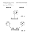
- FIG. 3 illustrates various alternate carriers for use in the present invention.
- FIG. 3A depicts a carrier/actuator drive arrangement utilizing a take-up reel.
- FIG. 3B depicts a pair of take-up reels with associated guides.
- FIG. 4 illustrates a polymerization inhibitor in a rigid build plate aiding to establish a non-polymerized film on the build surface thereof.
- a drop of ultraviolet (UV) curable adhesive was placed on a metal plate and covered with 10 mm thick plate of TEFLON® AF fluoropolymer ( FIG. 4A ), followed by application of UV radiation to the adhesive from the side of TEFLON® AF ( FIG. 4B ). After UV exposure the two plates were separated ( FIG. 4C ).
- the resulting non-polymerized film on the build surface was compared to control experiments using clean glass ( FIG. 4D-4F ) and glass treated with a release layer ( FIG. 4G-4I )
- FIG. 5 illustrates the migration of an inhibitor (in this case oxygen) through a build plate from a feed surface on the back of the plate to a build surface on the front of a plate to aid in establishing a non-polymerized film on the build surface.
- Samples 1 and 2 were prepared in a similar manner wherein a drop of UV curable adhesive was placed on a metal plate and covered with 10 mm thick plate of TEFLON® AF fluoropolymer ( FIG. 5A ) then exposed to a nitrogen environment to eliminate the presence of oxygen ( FIG. 5B ). Both samples were brought into a standard atmosphere environment and Sample 1 was immediately exposed to UV radiation while Sample 2 was exposed to UV radiation 10 minutes after being in the atmosphere environment. Both samples received the same amount of UV radiation ( FIG. 5C and FIG. 5E ). The characteristics of the adhesive in both samples are shown in FIG. 5D and FIG. 5F , respectively.
- an inhibitor in this case oxygen
- FIG. 6 schematically illustrates a growing three-dimensional object being advanced away from a build surface, and the gap that must be filled therebetween before subsequent polymerization can be carried out.
- FIG. 7 schematically illustrates an embodiment of the invention which provides for the application of pressure to speed the filling of the gap shown in FIG. 8 .
- FIG. 8 illustrates a rod or fiber that can be produced by the methods and apparatus of the present invention.
- spatially relative terms such as “under,” “below,” “lower,” “over,” “upper” and the like, may be used herein for ease of description to describe an element's or feature's relationship to another element(s) or feature(s) as illustrated in the figures. It will be understood that the spatially relative terms are intended to encompass different orientations of the device in use or operation in addition to the orientation depicted in the figures. For example, if the device in the figures is inverted, elements described as “under” or “beneath” other elements or features would then be oriented “over” the other elements or features. Thus the exemplary term “under” can encompass both an orientation of over and under.
- the device may otherwise be oriented (rotated 90 degrees or at other orientations) and the spatially relative descriptors used herein interpreted accordingly.
- the terms “upwardly,” “downwardly,” “vertical,” “horizontal” and the like are used herein for the purpose of explanation only, unless specifically indicated otherwise.
- first, second, etc. may be used herein to describe various elements, components, regions, layers and/or sections, these elements, components, regions, layers and/or sections should not be limited by these terms. Rather, these terms are only used to distinguish one element, component, region, layer and/or section, from another element, component, region, layer and/or section. Thus, a first element, component, region, layer or section discussed herein could be termed a second element, component, region, layer or section without departing from the teachings of the present invention.
- the sequence of operations (or steps) is not limited to the order presented in the claims or figures unless specifically indicated otherwise.
- the liquid can include a monomer, particularly photopolymerizable and/or free radical polymerizable monomers, a suitable initiator such as a free radical initiator, and combinations thereof.
- suitable initiator such as a free radical initiator
- examples include, but are not limited to, acrylics, methacrylics, acrylamides, styrenics, olefins, halogenated olefins, cyclic alkenes, maleic anhydride, alkenes, alkynes, carbon monoxide, functionalized oligomers, multifunctional cute site monomers, functionalized PEGs, etc., including combinations thereof.
- liquid resins, monomers and initiators include but are not limited to those set forth in U.S. Pat. Nos. 8,232,043; 8,119,214; 7,935,476; 7,767,728; and 7,649,029.
- the liquid resin or polymerizable material can have solid particles suspended or dispersed therein. Any suitable solid particle can be used, depending upon the end product being fabricated.
- the particles can be metallic, organic/polymeric, inorganic, or composites or mixtures thereof.
- the particles can be of any suitable shape, including spherical, elliptical, cylindrical, etc.
- the particles can comprise an active agent or detectable compound as described below, though these may also be provided dissolved solubilized in the liquid resin as also discussed below.
- magnetic or paramagnetic particles or nanoparticles can be employed.
- the liquid resin can have additional ingredients solubilized therein, including pigments, dyes, active compounds or pharmaceutical compounds, detectable compounds (e.g., fluorescent, phosphorescent, radioactive), etc., again depending upon the particular purpose of the product being fabricated.
- additional ingredients include, but are not limited to, proteins, peptides, nucleic acids (DNA, RNA) such as siRNA, sugars, small organic compounds (drugs and drug-like compounds), etc., including combinations thereof.
- Inhibitors or polymerization inhibitors for use in the present invention may be in the form of a liquid or a gas.
- gas inhibitors are preferred.
- the specific inhibitor will depend upon the monomer being polymerized and the polymerization reaction.
- the inhibitor can conveniently be oxygen, which can be provided in the form of a gas such as air, a gas enriched in oxygen (optionally but in some embodiments preferably containing additional inert gases to reduce combustibility thereof), or in some embodiments pure oxygen gas.
- the inhibitor can be a base such as trace amines or carbon dioxide.
- FIG. 1 A non-limiting embodiment of an apparatus of the invention is shown in FIG. 1 . It comprises a radiation source 11 such as a digital light processor (DLP) providing electromagnetic radiation 12 which though reflective mirror 13 illuminates a build chamber defined by wall 14 and a rigid build plate 15 forming the bottom of the build chamber, which build chamber is filled with liquid resin 16 .
- the bottom of the chamber 15 is constructed of rigid build plate comprising a rigid semipermeable member as discussed further below.
- the top of the object under construction 17 is attached to a carrier 18 .
- the carrier is driven in the vertical direction by linear stage 19 , although alternate structures can be used as discussed below.
- a liquid resin reservoir, tubing, pumps liquid level sensors and/or valves can be included to replenish the pool of liquid resin in the build chamber (not shown for clarity) though in some embodiments a simple gravity feed may be employed.
- Drives/actuators for the carrier or linear stage, along with associated wiring, can be included in accordance with known techniques (again not shown for clarity).
- the drives/actuators, radiation source, and in some embodiments pumps and liquid level sensors can all be operatively associated with a suitable controller, again in accordance with known techniques.
- Build plates 15 used to carry out the present invention generally comprise or consist of a a rigid semipermeable (or gas permeable) member, alone or in combination with one or more additional supporting substrates.
- the rigid semipermeable member can be made of any suitable material that is optically transparent at the relevant wavelengths (or otherwise transparent to the radiation source), including but not limited porous or microporous glass, and the rigid gas permeable polymers used for the manufacture of rigid gas permeable contact lenses. See, e.g., Norman G. Gaylord, U.S. Pat. No. RE31,406; see also U.S. Pat. Nos.
- the rigid semipermeable member is formed of a material that does not swell when contacted to the liquid resin or material to be polymerized. Suitable materials for the rigid semipermeable member include rigid amorphous fluoropolymers, such as those described in U.S. Pat. Nos. 5,308,685 and 5,051,115.
- Particular materials include TEFLON AF® fluoropolymers, commercially available from DuPont. Additional materials include perfluoropolyether polymers such as described in U.S. Pat. Nos. 8,268,446; 8,263,129; 8,158,728; and 7,435,495.
- the semipermeable member typically comprises a top surface portion, a bottom surface portion, and an edge surface portion.
- the build surface is on the top surface portion; and the feed surface may be on one, two, or all three of the top surface portion, the bottom surface portion, and/or the edge surface portion.
- the feed surface is on the bottom surface portion, but alternate configurations where the feed surface is provided on an edge, and/or on the top surface portion (close to but separate or spaced away from the build surface) can be implemented with routine skill.
- the semipermeable member has, in some embodiments, a thickness of from 0.1 or 1 millimeters to 10 or 100 millimeters (depending upon the size of the item being fabricated, whether or not it is laminated to or in contact with an additional supporting plate such as glass, etc.
- the permeability of the rigid semipermeable member will depend upon conditions such as the pressure of the atmosphere and/or inhibitor, the choice of inhibitor, the rate or speed of fabrication, etc.
- the permeability of the semipermeable member to oxygen may be from 10 or 20 Barrers, up to 1000 or 2000 Barrers, or more.
- a semipermeable member with a permeability of 10 Barrers used with a pure oxygen, or highly enriched oxygen, atmosphere under a pressure of 150 PSI may perform substantially the same as a semipermeable member with a permeability of 500 Barrers when the oxygen is supplied from the ambient atmosphere under atmospheric conditions.
- the various components are mounted on a support or frame assembly 20 .
- the support or frame assembly is comprised of a base 21 to which the radiation source 11 is securely or rigidly attached, a vertical member 22 to which the linear stage is operatively associated, and a horizontal table 23 to which wall 14 is removably or securely attached (or on which the wall is placed), and with the build plate rigidly fixed, either permanently or removably, to form the build chamber as described above.
- the build plate can consist of a single unitary and integral piece of a rigid semipermeable member, or can comprise additional materials.
- a porous or microporous glass can be laminated or fixed to a rigid semipermeable material.
- a semipermeable member as an upper portion can be fixed to a transparent lower member having purging channels formed therein for feeding gas carrying the polymerization inhibitor to the semipermeable member (through which it passes to the build surface to facilitate the formation of a release layer of unpolymerized liquid material, as noted above and below).
- Such purge channels may extend fully or partially through the base plate: For example, the purge channels may extend partially into the base plate, but then end in the region directly underlying the build surface to avoid introduction of distortion. Specific geometries will depend upon whether the feed surface for the inhibitor into the semipermeable member is located on the same side or opposite side as the build surface, on an edge portion thereof, or a combination of several thereof.
- any suitable radiation source can be used, depending upon the particular resin employed, including electron beam and ionizing radiation sources.
- the radiation source is an actinic radiation source, such as one or more light sources, and in particular one or more ultraviolet light sources.
- Any suitable light source can be used, such as a laser, light-emitting diode, etc., including arrays thereof.
- the light source preferably includes a pattern-forming element operatively associated with a controller, as noted above.
- the light source or pattern forming element comprises a digital micromirror device (DMD) with digital light processing (DLP), a spatial modulator (SLM), or a microelectromechanical system (MEMS) mirror array, a mask (aka a reticle), a silhouette, or a combination thereof.
- DMD digital micromirror device
- DLP digital light processing
- SLM spatial modulator
- MEMS microelectromechanical system
- FIGS. 3A-3B Alternate carriers and actuator/drive arrangements are shown in FIGS. 3A-3B . Numerous variations can be employed, including a take-up reel, an XYZ drive assembly (e.g., as commonly used on an automated microscope stage), etc.
- the drive assembly will generally comprise a worm gear and motor, a rack and pinion and motor, a hydraulic, pneumatic, or piezoelectric drive, or the like, adapted to move or advance the carrier away from the build surface in the vertical or “Z” direction only.
- a spool or take-up real can be utilized, with associated drives or actuators and guides (not shown), particularly when the product being fabricated is an elongated rod or fiber (discussed further below).
- a pair of take-up reels with associated guides, and associated drives or actuators can be mounted on linear stage 19 to provide movement in either the X and/or Y direction, in alternative to, or in addition to or in combination with, movement in the Z direction provided by linear stage 19 .
- an XYZ drive assembly like that used in an automated microscope can be used in place of linear stage 19 to move or advance the carrier away from the build surface in the X, Y, and/or Z direction, e.g., at an angle, or at changing angles, or combinations of directions at various stages.
- advancement away from the build plate can be carried out solely in the Z (or vertical) direction, solely in the X and/or Y (horizontal) directions, in at least the Z direction, or in at least the X and/or Y directions, by combining movement in the Z direction with movement in the X and/or Y directions.
- the present invention provides a method of forming a three-dimensional object, comprising the steps of: (a) providing a carrier and a build plate, said build plate comprising a f semipermeable member, said semipermeable member comprising a build surface and a feed surface separate from said build surface, with said build surface and said carrier defining a build region therebetween, and with said feed surface in fluid contact with a polymerization inhibitor; then (concurrently and/or sequentially) (b) filing said build region with a polymerizable liquid, said polymerizable liquid contacting said build segment, (c) irradiating said build region through said build plate to produce a solid polymerized region in said build region, with a liquid film release layer comprised of said polymerizable liquid formed between said solid polymerized region and said build surface, the polymerization of which liquid film is inhibited by said polymerization inhibitor; and (d) advancing said carrier with said polymerized region adhered thereto away from said build surface on said stationary build plate to
- the method includes (e) continuing and/or repeating steps (b) through (d) to produce a subsequent polymerized region adhered to a previous polymerized region until the continued or repeated deposition of polymerized regions adhered to one another forms said three-dimensional object.
- the method can be carried out in a continuous fashion, though it will be appreciated that the individual steps noted above may be carried out sequentially, concurrently, or a combination thereof. Indeed, the rate of steps can be varied over time depending upon factors such as the density and/or complexity of the region under fabrication.
- the advancing step is carried out sequentially in uniform increments (e.g., of from 0.1 or 1 microns, up to 10 or 100 microns, or more) for each step or increment. In some embodiments, the advancing step is carried out sequentially in variable increments (e.g., each increment ranging from 0.1 or 1 microns, up to 10 or 100 microns, or more) for each step or increment.
- the size of the increment, along with the rate of advancing, will depend in part upon the presence or absence of pressure for the introducing step, as discussed further below.
- the filling step is carried out by forcing said polymerizable liquid into said build region under pressure.
- the advancing step or steps may be carried out at a rate or cumulative or average rate of at least 0.1, 1, 10, 50, 100, 500 or 1000 microns per second, or more.
- the pressure may be whatever is sufficient to increase the rate of said advancing step(s) at least 2, 4, 6, 8 or 10 times as compared to the maximum rate of repetition of said advancing steps in the absence of said pressure.
- a pressure of 10, 20, 30 or 40 pounds per square inch (PSI) up to, 200, 300, 400 or 500 PSI or more may be used.
- PSI pounds per square inch
- both the feed surface and the polymerizable liquid can be are in fluid contact with the same compressed gas (e.g., one comprising from 20 to 95 percent by volume of oxygen, the oxygen serving as the polymerization inhibitor.
- the size of the pressure vessel can be kept smaller relative to the size of the product being fabricated and higher pressures can (if desired) be more readily utilized.
- the irradiating step is in some embodiments carried out with patterned irradiation.
- the patterned irradiation may be a fixed pattern or may be a variable pattern created by a pattern generator (e.g., a DLP) as discussed above, depending upon the particular item being fabricated.
- a pattern generator e.g., a DLP
- the build surface is flat; in other the build surface is irregular such as convexly or concavely curved, or has walls or trenches formed therein. In either case the build surface may be smooth or textured. Curved and/or irregular build plates or build surfaces can be used in fiber or rod formation, to provide different materials to a single object being fabricated (that is, different polymerizable liquids to the same build surface through channels or trenches formed in the build surface, each associated with a separate liquid supply, etc.
- Numerous different products can be made by the methods and apparatus of the present invention, including both large-scale models or prototypes, small custom products, miniature or microminiature products or devices, etc.
- Examples include, but are not limited to, medical devices and implantable medical devices such as stents, drug delivery depots, functional structures, fibers and rods such as waveguides, micromechanical devices, microfluidic devices, etc.
- the product can have a height of from 0.1 or 1 millimeters up to 10 or 100 millimeters, or more, and/or a maximum width of from 0.1 or 1 millimeters up to 10 or 100 millimeters, or more.
- the product can have a height of from 10 or 100 nanometers up to 10 or 100 microns, or more, and/or a maximum width of from 10 or 100 nanometers up to 10 or 100 microns, or more.
- the ratio of height to width of the product is at least 2:1, 10:1, 50:1, or 100:1, or more, or a width to height ratio of 1:1, 10:1, 50:1, or 100:1, or more.
- the product has at least one, or a plurality of, pores or channels formed therein, as discussed further below.
- UV curable adhesive A drop of ultraviolet (UV) curable adhesive was placed on a metal plate and covered with 10 mm thick plate of TEFLON® AF fluoropolymer (a rigid, amorphous, glassy polymer) as shown in FIG. 4A .
- UV radiation was supplied to the adhesive from the side of TEFLON® AF as shown in FIG. 4B . After UV exposure the two plates were separated. It was found that no force was required to separate the two plates.
- the adhesive was cured only next to the metal plate, and that a thin film of uncured adhesive was present on the Teflon AF fluoropolymer plate and also on the cured portion of the adhesive as shown in FIG. 4C .
- FIGS. 4D-4F Two controlled experiments were also performed where clean glass ( FIGS. 4D-4F ) and also glass treated with a release layer ( FIGS. 4G-4I ) was used. It was confirmed that considerable force was needed to separate clean glass from the metal and it was found that adhesive remained on the glass. Less force was needed to separate the treated glass, while adhesive remained on the metal plate.
- Teflon AF has a very high oxygen permeability coefficient. Constant supply of oxygen through 10 mm think Teflon AF is sufficient to prevent a thin layer of acrylate adhesive from polymerization.
- the thickness of uncured adhesive layer in the above experiment was on the order of 10 microns and it can be increased or decreased by varying the amount of photo initiator present in the adhesive.
- Samples 1 and 2 were prepared in a similar manner wherein a drop of UV curable adhesive was placed on a metal plate and covered with 10 mm thick plate of TEFLON® AF fluoropolymer as shown in FIG. 5A . Both samples were exposed to a nitrogen environment to eliminate any presence of oxygen as shown in FIG. 5B . Next both samples were brought into a standard atmosphere environment and Sample 1 was immediately exposed to UV radiation while Sample 2 was exposed to UV radiation 10 minutes after being in the atmosphere environment. Both samples were exposed to the same amount of UV radiation as shown in FIG. 5C and FIG. 5E . Upon examination of the samples after UV exposure it was discovered that the adhesive was cured completely in Sample 1 as shown in FIG. 5D and only next to the metal plate in Sample 2 as shown in FIG.
- a highly oxygen permeable, rigid, and UV transparent material is to used as the bottom of a chamber filled with photocurable resin in a device of the invention.
- the top of an object is attached to a support plate which is moved up at a substantially constant speed while the bottom portion of the object is constantly being formed just above the bottom of the chamber.
- the gap between the bottom of the object and the bottom of the chamber is always filled with resin.
- the resin in the gap is constantly replenished with supply resin contained in the chamber.
- the speed of the object's formation depends on the viscosity of the resin ⁇ , atmospheric pressure P, the height of the gap between the object and the bottom of the chamber h, and the linear dimension L of the object's bottom surface. Simple calculations are performed to estimate this speed using the theory of viscous flow between two parallel plates.
- the time ⁇ which is required to fill the gap shown on FIG. 6 is given by the equation:
- the gap of uncured resin can be controlled by altering the physical environment in the enclosed chamber contacting feed surface.
- an atmosphere of pure oxygen, or enriched in oxygen e.g., 95% oxygen 5% carbon dioxide
- oxygen e.g., 95% oxygen 5% carbon dioxide
- the methods of the present invention can be used to make an elongate rod or fiber as shown in FIG. 8 , the rod or fiber having (for example) a width or diameter of 0.01 or 0.1 to 10 or 100 millimeters. While a circular cross-section is shown, any suitable cross-section can be utilized, including elliptical, polygonal (triangular, square, pentagonal, hexagonal, etc.) irregular, and combinations thereof.
- the rod or fiber can have a plurality of elongated pores or channels formed therein (e.g., 1, 10, 100 1,000, 10,000 or 100,000 or more) of any suitable diameter (e.g., 0.1 or 1 microns, up to 10 or 100 microns or more) and any suitable cross-section as described above.
- Unpolymerized liquid in the pores or channels can be removed (if desired) by any suitable technique, such as blowing, pressure, vacuum, heating, drying and combinations thereof.
- the length of the rod or fiber can be increased by utilizing a take-up reel as described above, and the speed of fabrication of the rod or fiber can be increased by carrying out the polymerization under pressure as described above.
- a plurality of such rods or fibers can be constructed concurrently from a single build plate by providing a plurality of independent carriers or take-up reels.
- Such rods or fibers can be used for any purpose, such as utilizing each pore or channel therein as an independent channel in a microfluidic system.
Abstract
Description
Assuming:
-
- L˜100 mm
- h˜100 microns
- η˜100 cPoise
- P˜1 atm
In this illustrative embodiment, the time τ is estimated to be of an order of 1 second, resulting in fabrication speeds of 100 microns per second or 5 minutes per inch. These calculations assume that the thickness of the uncured resin is maintained at about 100 microns. Depending on the chemistry of the resin and permeability of the base plate, this parameter may vary. If for example, the gap is 25 microns, then fabrication speeds at atmospheric pressure will decrease according toEquation 1 by a factor of 16. However, increasing, the ambient pressure to greater than atmospheric pressure, e.g., by applying external pressure on the order of 150 PSI as shown inFIG. 7 , may in some embodiments increase fabrication speed by a factor of 10.
Claims (9)
Priority Applications (3)
| Application Number | Priority Date | Filing Date | Title |
|---|---|---|---|
| US14/154,700 US9498920B2 (en) | 2013-02-12 | 2014-01-14 | Method and apparatus for three-dimensional fabrication |
| US15/297,511 US9993974B2 (en) | 2013-02-12 | 2016-10-19 | Method and apparatus for three-dimensional fabrication |
| US15/972,729 US10710305B2 (en) | 2013-02-12 | 2018-05-07 | Method and apparatus for three-dimensional fabrication |
Applications Claiming Priority (2)
| Application Number | Priority Date | Filing Date | Title |
|---|---|---|---|
| US201361763746P | 2013-02-12 | 2013-02-12 | |
| US14/154,700 US9498920B2 (en) | 2013-02-12 | 2014-01-14 | Method and apparatus for three-dimensional fabrication |
Related Child Applications (1)
| Application Number | Title | Priority Date | Filing Date |
|---|---|---|---|
| US15/297,511 Continuation US9993974B2 (en) | 2013-02-12 | 2016-10-19 | Method and apparatus for three-dimensional fabrication |
Publications (2)
| Publication Number | Publication Date |
|---|---|
| US20140361463A1 US20140361463A1 (en) | 2014-12-11 |
| US9498920B2 true US9498920B2 (en) | 2016-11-22 |
Family
ID=52004798
Family Applications (3)
| Application Number | Title | Priority Date | Filing Date |
|---|---|---|---|
| US14/154,700 Active 2034-11-28 US9498920B2 (en) | 2013-02-12 | 2014-01-14 | Method and apparatus for three-dimensional fabrication |
| US15/297,511 Active US9993974B2 (en) | 2013-02-12 | 2016-10-19 | Method and apparatus for three-dimensional fabrication |
| US15/972,729 Active US10710305B2 (en) | 2013-02-12 | 2018-05-07 | Method and apparatus for three-dimensional fabrication |
Family Applications After (2)
| Application Number | Title | Priority Date | Filing Date |
|---|---|---|---|
| US15/297,511 Active US9993974B2 (en) | 2013-02-12 | 2016-10-19 | Method and apparatus for three-dimensional fabrication |
| US15/972,729 Active US10710305B2 (en) | 2013-02-12 | 2018-05-07 | Method and apparatus for three-dimensional fabrication |
Country Status (1)
| Country | Link |
|---|---|
| US (3) | US9498920B2 (en) |
Cited By (75)
| Publication number | Priority date | Publication date | Assignee | Title |
|---|---|---|---|---|
| US20150197063A1 (en) * | 2014-01-12 | 2015-07-16 | Zohar SHINAR | Device, method, and system of three-dimensional printing |
| US20170100885A1 (en) * | 2014-06-20 | 2017-04-13 | Carbon, Inc. | Three-Dimensional Printing Using Tiled Light Engines |
| US20180009162A1 (en) * | 2015-02-05 | 2018-01-11 | Carbon, Inc. | Method of additive manufacturing by intermittent exposure |
| US9975295B2 (en) | 2014-08-12 | 2018-05-22 | Carbon, Inc. | Acceleration of stereolithography |
| US10150280B2 (en) | 2013-05-14 | 2018-12-11 | Holo, Inc. | Apparatus for fabrication of three dimensional objects |
| US10155345B2 (en) | 2015-02-05 | 2018-12-18 | Carbon, Inc. | Method of additive manufacturing by fabrication through multiple zones |
| US10155882B2 (en) | 2014-06-23 | 2018-12-18 | Carbon, Inc. | Methods of producing EPOXY three-dimensional objects from materials having multiple mechanisms of hardening |
| WO2018237038A1 (en) | 2017-06-21 | 2018-12-27 | Carbon, Inc. | Method of additive manufacturing |
| US10166725B2 (en) | 2014-09-08 | 2019-01-01 | Holo, Inc. | Three dimensional printing adhesion reduction using photoinhibition |
| US10232605B2 (en) | 2014-03-21 | 2019-03-19 | Carbon, Inc. | Method for three-dimensional fabrication with gas injection through carrier |
| US10245785B2 (en) | 2017-06-16 | 2019-04-02 | Holo, Inc. | Methods for stereolithography three-dimensional printing |
| WO2019084112A1 (en) | 2017-10-27 | 2019-05-02 | Carbon, Inc. | Reduction of polymerization inhibitor irregularity on additive manufacturing windows |
| WO2019083833A1 (en) | 2017-10-23 | 2019-05-02 | Carbon, Inc. | Window variability correction in additive manufacturing |
| US10316213B1 (en) | 2017-05-01 | 2019-06-11 | Formlabs, Inc. | Dual-cure resins and related methods |
| US10335997B2 (en) | 2017-10-02 | 2019-07-02 | Global Filtration Systems | Method of stabilizing a photohardening inhibitor-permeable film in the manufacture of three-dimensional objects |
| US10391711B2 (en) | 2015-03-05 | 2019-08-27 | Carbon, Inc. | Fabrication of three dimensional objects with multiple operating modes |
| US10421233B2 (en) | 2017-05-15 | 2019-09-24 | Holo, Inc. | Viscous film three-dimensional printing systems and methods |
| US10471699B2 (en) | 2014-06-20 | 2019-11-12 | Carbon, Inc. | Three-dimensional printing with reciprocal feeding of polymerizable liquid |
| WO2019222094A1 (en) | 2018-05-14 | 2019-11-21 | Carbon, Inc. | Stereolithography apparatus with individually addressable light source arrays |
| US10596755B2 (en) | 2013-02-12 | 2020-03-24 | Carbon, Inc. | Method for three-dimensional fabrication |
| US10611080B2 (en) | 2015-12-22 | 2020-04-07 | Carbon, Inc. | Three-dimensional printing using selectively lockable carriers |
| US10647054B2 (en) | 2015-12-22 | 2020-05-12 | Carbon, Inc. | Accelerants for additive manufacturing with dual cure resins |
| US10661501B2 (en) | 2014-06-20 | 2020-05-26 | Carbon, Inc. | Three-dimensional printing method using increased light intensity and apparatus therefor |
| US10668709B2 (en) | 2014-08-12 | 2020-06-02 | Carbon, Inc. | Three-dimensional printing using carriers with release mechanisms |
| WO2020117490A1 (en) | 2018-12-03 | 2020-06-11 | Carbon, Inc. | Window thermal profile calibration in additive manufacturing |
| US10688737B2 (en) | 2017-09-14 | 2020-06-23 | General Electric Company | Method for forming fiber-reinforced polymer components |
| WO2020131675A1 (en) | 2018-12-21 | 2020-06-25 | Carbon, Inc. | Energy absorbing dual cure polyurethane elastomers for additive manufacturing |
| WO2020146092A1 (en) | 2019-01-09 | 2020-07-16 | Carbon, Inc. | Systems and apparatuses for additive manufacturing with process update and lock down |
| US10766194B1 (en) | 2019-02-21 | 2020-09-08 | Sprintray Inc. | Apparatus, system, and method for use in three-dimensional printing |
| US10792868B2 (en) | 2015-09-09 | 2020-10-06 | Carbon, Inc. | Method and apparatus for three-dimensional fabrication |
| US10821668B2 (en) | 2018-01-26 | 2020-11-03 | General Electric Company | Method for producing a component layer-by- layer |
| US10821669B2 (en) | 2018-01-26 | 2020-11-03 | General Electric Company | Method for producing a component layer-by-layer |
| US10933580B2 (en) | 2016-12-14 | 2021-03-02 | Carbon, Inc. | Continuous liquid interface production with force monitoring and feedback |
| US10935891B2 (en) | 2017-03-13 | 2021-03-02 | Holo, Inc. | Multi wavelength stereolithography hardware configurations |
| WO2021040898A1 (en) | 2019-08-30 | 2021-03-04 | Carbon, Inc. | Divided resin cassettes for enhanced work flow in additive manufacturing of dental products and the like |
| US10967578B2 (en) | 2017-07-11 | 2021-04-06 | Daniel S. Clark | 5D part growing machine with volumetric display technology |
| US11077608B2 (en) | 2018-02-21 | 2021-08-03 | Carbon, Inc. | Enhancing adhesion of objects to carriers during additive manufacturing |
| US11084216B2 (en) | 2018-04-23 | 2021-08-10 | Carbon, Inc. | Resin extractor for additive manufacturing |
| US11117315B2 (en) | 2018-03-21 | 2021-09-14 | Carbon, Inc. | Additive manufacturing carrier platform with window damage protection features |
| US11130286B2 (en) | 2016-09-07 | 2021-09-28 | Canon Kabushiki Kaisha | Three-dimensional manufacturing apparatus, three-dimensional manufactured object producing method, and container for three-dimensional manufacturing apparatus |
| WO2021202655A1 (en) | 2020-04-03 | 2021-10-07 | Carbon, Inc. | Resins and methods for additive manufacturing of energy absorbing three-dimensional objects |
| US11141910B2 (en) | 2013-08-14 | 2021-10-12 | Carbon, Inc. | Continuous liquid interphase printing |
| US11141919B2 (en) | 2015-12-09 | 2021-10-12 | Holo, Inc. | Multi-material stereolithographic three dimensional printing |
| US11179891B2 (en) | 2019-03-15 | 2021-11-23 | General Electric Company | Method and apparatus for additive manufacturing with shared components |
| US11192305B2 (en) | 2018-08-24 | 2021-12-07 | Carbon, Inc. | Window cassettes for reduced polymerization inhibitor irregularity during additive manufacturing |
| US11220054B2 (en) | 2017-10-02 | 2022-01-11 | Global Filtration Systems | Method of stabilizing a photohardening inhibitor-permeable film in the manufacture of three-dimensional objects |
| US11230050B2 (en) | 2018-02-27 | 2022-01-25 | Carbon, Inc. | Lattice base structures for additive manufacturing |
| US11247389B2 (en) | 2019-01-07 | 2022-02-15 | Carbon, Inc. | Systems and methods for resin recovery in additive manufacturing |
| US11254052B2 (en) | 2017-11-02 | 2022-02-22 | General Electric Company | Vatless additive manufacturing apparatus and method |
| US11351724B2 (en) | 2017-10-03 | 2022-06-07 | General Electric Company | Selective sintering additive manufacturing method |
| US11351735B2 (en) | 2018-12-26 | 2022-06-07 | Holo, Inc. | Sensors for three-dimensional printing systems and methods |
| US11376792B2 (en) | 2018-09-05 | 2022-07-05 | Carbon, Inc. | Robotic additive manufacturing system |
| US11407183B2 (en) | 2018-08-31 | 2022-08-09 | Carbon, Inc. | Additively manufactured objects with pre-formed bonding features and methods of making the same |
| US11420384B2 (en) | 2017-10-03 | 2022-08-23 | General Electric Company | Selective curing additive manufacturing method |
| US11426938B2 (en) | 2018-02-21 | 2022-08-30 | Carbon, Inc. | Rapid wash system for additive manufacturing |
| US11440259B2 (en) | 2020-01-31 | 2022-09-13 | Carbon, Inc. | Resin reclamation centrifuge rotor for additively manufactured objects |
| US11440244B2 (en) | 2015-12-22 | 2022-09-13 | Carbon, Inc. | Dual precursor resin systems for additive manufacturing with dual cure resins |
| US11478987B2 (en) | 2016-12-14 | 2022-10-25 | Carbon, Inc. | Methods and apparatus for washing objects produced by stereolithography |
| US11491725B2 (en) | 2020-10-09 | 2022-11-08 | Carbon, Inc. | Vapor spin cleaning of additively manufactured parts |
| US11498283B2 (en) | 2019-02-20 | 2022-11-15 | General Electric Company | Method and apparatus for build thickness control in additive manufacturing |
| US11504905B2 (en) | 2018-02-21 | 2022-11-22 | Carbon, Inc. | Methods of reducing distortion of additively manufactured objects |
| US11534945B2 (en) * | 2018-11-26 | 2022-12-27 | Directed Energy Materials LLC | Bragg-peak three-dimensional manufacturing with resins |
| US11541600B2 (en) | 2018-03-20 | 2023-01-03 | Carbon, Inc. | Rapid wash carrier platform for additive manufacturing of dental models |
| US11590691B2 (en) | 2017-11-02 | 2023-02-28 | General Electric Company | Plate-based additive manufacturing apparatus and method |
| US11679555B2 (en) | 2019-02-21 | 2023-06-20 | Sprintray, Inc. | Reservoir with substrate assembly for reducing separation forces in three-dimensional printing |
| US11731367B2 (en) | 2021-06-23 | 2023-08-22 | General Electric Company | Drive system for additive manufacturing |
| US11786711B2 (en) | 2013-08-14 | 2023-10-17 | Carbon, Inc. | Continuous liquid interphase printing |
| US11794412B2 (en) | 2019-02-20 | 2023-10-24 | General Electric Company | Method and apparatus for layer thickness control in additive manufacturing |
| US11813799B2 (en) | 2021-09-01 | 2023-11-14 | General Electric Company | Control systems and methods for additive manufacturing |
| US11826950B2 (en) | 2021-07-09 | 2023-11-28 | General Electric Company | Resin management system for additive manufacturing |
| US11840023B2 (en) | 2019-08-30 | 2023-12-12 | Carbon, Inc. | Mutliphysics model for inverse warping of data file in preparation for additive manufacturing |
| US11919246B2 (en) | 2017-07-11 | 2024-03-05 | Daniel S. Clark | 5D part growing machine with volumetric display technology |
| US11919236B2 (en) | 2018-09-26 | 2024-03-05 | Carbon, Inc. | Spin cleaning method and apparatus for additive manufacturing |
| US11951679B2 (en) | 2021-06-16 | 2024-04-09 | General Electric Company | Additive manufacturing system |
| US11958249B2 (en) | 2022-06-10 | 2024-04-16 | General Electric Company | Reclamation system for additive manufacturing |
Families Citing this family (56)
| Publication number | Priority date | Publication date | Assignee | Title |
|---|---|---|---|---|
| ITVI20120183A1 (en) * | 2012-07-27 | 2014-01-28 | Dws Srl | CARTRIDGE FOR STEREOLITHOGRAPHIC MACHINE, STEREOLITHOGRAPHIC MACHINE INCLUDING SUCH CARTRIDGE AND METHOD OF PRODUCTION OF SUCH CARTRIDGE |
| WO2014079478A1 (en) | 2012-11-20 | 2014-05-30 | Light In Light Srl | High speed laser processing of transparent materials |
| EP2754524B1 (en) | 2013-01-15 | 2015-11-25 | Corning Laser Technologies GmbH | Method of and apparatus for laser based processing of flat substrates being wafer or glass element using a laser beam line |
| US9308583B2 (en) * | 2013-03-05 | 2016-04-12 | Lawrence Livermore National Security, Llc | System and method for high power diode based additive manufacturing |
| EP2781296B1 (en) | 2013-03-21 | 2020-10-21 | Corning Laser Technologies GmbH | Device and method for cutting out contours from flat substrates using a laser |
| US9815730B2 (en) | 2013-12-17 | 2017-11-14 | Corning Incorporated | Processing 3D shaped transparent brittle substrate |
| US10442719B2 (en) | 2013-12-17 | 2019-10-15 | Corning Incorporated | Edge chamfering methods |
| US9701563B2 (en) | 2013-12-17 | 2017-07-11 | Corning Incorporated | Laser cut composite glass article and method of cutting |
| US9850160B2 (en) | 2013-12-17 | 2017-12-26 | Corning Incorporated | Laser cutting of display glass compositions |
| US9676167B2 (en) | 2013-12-17 | 2017-06-13 | Corning Incorporated | Laser processing of sapphire substrate and related applications |
| US11556039B2 (en) | 2013-12-17 | 2023-01-17 | Corning Incorporated | Electrochromic coated glass articles and methods for laser processing the same |
| US20150165560A1 (en) | 2013-12-17 | 2015-06-18 | Corning Incorporated | Laser processing of slots and holes |
| US9517963B2 (en) | 2013-12-17 | 2016-12-13 | Corning Incorporated | Method for rapid laser drilling of holes in glass and products made therefrom |
| WO2016007572A1 (en) | 2014-07-08 | 2016-01-14 | Corning Incorporated | Methods and apparatuses for laser processing materials |
| CN208586209U (en) | 2014-07-14 | 2019-03-08 | 康宁股份有限公司 | A kind of system for forming multiple defects of restriction profile in workpiece |
| CN107073641B (en) | 2014-07-14 | 2020-11-10 | 康宁股份有限公司 | An interface block; system and method for cutting substrates transparent in the wavelength range using such an interface block |
| WO2016010954A2 (en) * | 2014-07-14 | 2016-01-21 | Corning Incorporated | Systems and methods for processing transparent materials using adjustable laser beam focal lines |
| EP3536440A1 (en) | 2014-07-14 | 2019-09-11 | Corning Incorporated | Glass article with a defect pattern |
| US11390062B2 (en) | 2014-08-12 | 2022-07-19 | Carbon, Inc. | Three-dimensional printing with supported build plates |
| US10047001B2 (en) | 2014-12-04 | 2018-08-14 | Corning Incorporated | Glass cutting systems and methods using non-diffracting laser beams |
| KR20170105562A (en) | 2015-01-12 | 2017-09-19 | 코닝 인코포레이티드 | Laser cutting of thermally tempered substrates using multiple photon absorption methods |
| US20160200052A1 (en) | 2015-01-13 | 2016-07-14 | Carbon3D, Inc. | Three-dimensional printing with build plates having surface topologies for increasing permeability and related methods |
| WO2016133759A1 (en) | 2015-02-20 | 2016-08-25 | Carbon3D, Inc. | Methods and apparatus for continuous liquid interface printing with electrochemically supported dead zone |
| US10792856B2 (en) * | 2015-03-13 | 2020-10-06 | Carbon, Inc. | Three-dimensional printing with flexible build plates |
| EP3848334A1 (en) | 2015-03-24 | 2021-07-14 | Corning Incorporated | Alkaline earth boro-aluminosilicate glass article with laser cut edge |
| JP2018516215A (en) * | 2015-03-27 | 2018-06-21 | コーニング インコーポレイテッド | Gas permeable window and manufacturing method thereof |
| US10814551B2 (en) * | 2015-04-02 | 2020-10-27 | Xerox Corporation | Three-dimensional printed part removal using an elastomer sheet |
| WO2016162363A1 (en) | 2015-04-09 | 2016-10-13 | Urbanalps Ag | Lock and key |
| EP3304201A4 (en) * | 2015-04-30 | 2019-06-26 | Castanon, Diego | Improved stereolithography system |
| CN107835794A (en) | 2015-07-10 | 2018-03-23 | 康宁股份有限公司 | The method of continuous manufacturing hole and product related to this in flexible substrate plate |
| WO2017040276A1 (en) * | 2015-08-28 | 2017-03-09 | Formlabs, Inc. | Techniques for additive fabrication process optimization and related systems and methods |
| CN108602249B (en) * | 2015-11-12 | 2021-03-02 | 克劳斯·斯塔德曼 | Stereolithography apparatus and drum mechanism |
| US10016661B2 (en) | 2016-04-06 | 2018-07-10 | Acushnet Company | Methods for making golf ball components using three-dimensional additive manufacturing systems |
| EP3957611A1 (en) | 2016-05-06 | 2022-02-23 | Corning Incorporated | Transparent substrates with improved edge surfaces |
| US10410883B2 (en) | 2016-06-01 | 2019-09-10 | Corning Incorporated | Articles and methods of forming vias in substrates |
| US10794679B2 (en) | 2016-06-29 | 2020-10-06 | Corning Incorporated | Method and system for measuring geometric parameters of through holes |
| LT3266594T (en) | 2016-07-07 | 2020-05-25 | Technische Universität Wien | Method and apparatus for lithography-based generative production of three-dimensional articles |
| CN106042388A (en) * | 2016-07-25 | 2016-10-26 | 东莞中国科学院云计算产业技术创新与育成中心 | 3D printing device, control system of 3D printing device and work method of 3D printing device |
| EP3490945B1 (en) | 2016-07-29 | 2020-10-14 | Corning Incorporated | Methods for laser processing |
| US10522963B2 (en) | 2016-08-30 | 2019-12-31 | Corning Incorporated | Laser cutting of materials with intensity mapping optical system |
| JP6866152B2 (en) * | 2016-12-22 | 2021-04-28 | キヤノン株式会社 | 3D modeling device and 3D modeling method |
| US10730783B2 (en) | 2016-09-30 | 2020-08-04 | Corning Incorporated | Apparatuses and methods for laser processing transparent workpieces using non-axisymmetric beam spots |
| EP3848333A1 (en) | 2016-10-24 | 2021-07-14 | Corning Incorporated | Substrate processing station for laser-based machining of sheet-like glass substrates |
| US10752534B2 (en) | 2016-11-01 | 2020-08-25 | Corning Incorporated | Apparatuses and methods for laser processing laminate workpiece stacks |
| US10688599B2 (en) | 2017-02-09 | 2020-06-23 | Corning Incorporated | Apparatus and methods for laser processing transparent workpieces using phase shifted focal lines |
| US11078112B2 (en) | 2017-05-25 | 2021-08-03 | Corning Incorporated | Silica-containing substrates with vias having an axially variable sidewall taper and methods for forming the same |
| US10580725B2 (en) | 2017-05-25 | 2020-03-03 | Corning Incorporated | Articles having vias with geometry attributes and methods for fabricating the same |
| US10626040B2 (en) | 2017-06-15 | 2020-04-21 | Corning Incorporated | Articles capable of individual singulation |
| CA3069982C (en) * | 2017-07-21 | 2023-08-01 | Saint-Gobain Performance Plastics Corporation | Method of forming a three-dimensional body |
| CN108327241B (en) * | 2018-01-28 | 2019-09-20 | 浙江大学 | A kind of manufacturing method of controllable antibacterial trachea bracket |
| US11554984B2 (en) | 2018-02-22 | 2023-01-17 | Corning Incorporated | Alkali-free borosilicate glasses with low post-HF etch roughness |
| WO2021015979A1 (en) | 2019-07-22 | 2021-01-28 | Specialized Bicycle Components, Inc. | Bicycle saddle |
| EP3812131B1 (en) | 2019-10-23 | 2022-04-13 | Ivoclar Vivadent AG | Stereolithography method |
| CA3177584A1 (en) * | 2020-05-01 | 2021-11-04 | Richard LUDINGTON | Vitreous carbon compositions, multi-layer laminates, and 3-d printed articles |
| US11340008B1 (en) * | 2021-01-20 | 2022-05-24 | Whirlpool Corporation | Appliance trim breaker assembly |
| USD990180S1 (en) | 2021-04-30 | 2023-06-27 | Specialized Bicycle Components, Inc. | Bicycle saddle |
Citations (77)
| Publication number | Priority date | Publication date | Assignee | Title |
|---|---|---|---|---|
| US4575330A (en) | 1984-08-08 | 1986-03-11 | Uvp, Inc. | Apparatus for production of three-dimensional objects by stereolithography |
| US4801477A (en) | 1987-09-29 | 1989-01-31 | Fudim Efrem V | Method and apparatus for production of three-dimensional objects by photosolidification |
| US4961154A (en) | 1986-06-03 | 1990-10-02 | Scitex Corporation Ltd. | Three dimensional modelling apparatus |
| US5059359A (en) | 1988-04-18 | 1991-10-22 | 3 D Systems, Inc. | Methods and apparatus for production of three-dimensional objects by stereolithography |
| US5122441A (en) | 1990-10-29 | 1992-06-16 | E. I. Du Pont De Nemours And Company | Method for fabricating an integral three-dimensional object from layers of a photoformable composition |
| US5143663A (en) | 1989-06-12 | 1992-09-01 | 3D Systems, Inc. | Stereolithography method and apparatus |
| US5143817A (en) | 1989-12-22 | 1992-09-01 | E. I. Du Pont De Nemours And Company | Solid imaging system |
| US5171490A (en) | 1988-11-29 | 1992-12-15 | Fudim Efrem V | Method and apparatus for production of three-dimensional objects by irradiation of photopolymers |
| DE4125534A1 (en) | 1991-08-01 | 1993-02-18 | Eos Electro Optical Syst | Three=dimensional layering - in which transparent sealed cover is used over bath to allow radiation through but exclude ambient atmos. |
| US5192559A (en) | 1990-09-27 | 1993-03-09 | 3D Systems, Inc. | Apparatus for building three-dimensional objects with sheets |
| US5198159A (en) | 1990-10-09 | 1993-03-30 | Matsushita Electric Works, Ltd. | Process of fabricating three-dimensional objects from a light curable resin liquid |
| US5236637A (en) | 1984-08-08 | 1993-08-17 | 3D Systems, Inc. | Method of and apparatus for production of three dimensional objects by stereolithography |
| US5247180A (en) | 1991-12-30 | 1993-09-21 | Texas Instruments Incorporated | Stereolithographic apparatus and method of use |
| US5263130A (en) | 1986-06-03 | 1993-11-16 | Cubital Ltd. | Three dimensional modelling apparatus |
| US5271882A (en) | 1990-11-09 | 1993-12-21 | Tokai Kogyo Kabushiki Kaisha | Blow molding process with sheet interposed between mold and product being molded |
| DE9319405U1 (en) | 1993-12-17 | 1994-03-31 | Forschungszentrum Informatik A | Device for producing a three-dimensional object (model) according to the principle of photofixing |
| US5447822A (en) | 1989-09-28 | 1995-09-05 | 3D Systems, Inc. | Apparatus and related method for forming a substantially flat stereolithographic working surface |
| US5523193A (en) | 1988-05-31 | 1996-06-04 | Texas Instruments Incorporated | Method and apparatus for patterning and imaging member |
| US5529473A (en) | 1990-07-05 | 1996-06-25 | E. I. Du Pont De Nemours And Company | Solid imaging system using differential tension elastomerc film |
| JPH08192469A (en) | 1995-01-20 | 1996-07-30 | Ushio Inc | Photo-setting resin curing method |
| US5554336A (en) | 1984-08-08 | 1996-09-10 | 3D Systems, Inc. | Method and apparatus for production of three-dimensional objects by stereolithography |
| US5597520A (en) | 1990-10-30 | 1997-01-28 | Smalley; Dennis R. | Simultaneous multiple layer curing in stereolithography |
| US5609812A (en) | 1988-04-18 | 1997-03-11 | 3D Systems, Inc. | Method of making a three-dimensional object by stereolithography |
| US5609813A (en) | 1988-04-18 | 1997-03-11 | 3D Systems, Inc. | Method of making a three-dimensional object by stereolithography |
| US5651934A (en) | 1988-09-26 | 1997-07-29 | 3D Systems, Inc. | Recoating of stereolithographic layers |
| US5772947A (en) | 1988-04-18 | 1998-06-30 | 3D Systems Inc | Stereolithographic curl reduction |
| US5824252A (en) | 1995-02-22 | 1998-10-20 | Apic Yamada Corporation | Method of resin molding and resin molding machine for the same |
| US5945058A (en) | 1997-05-13 | 1999-08-31 | 3D Systems, Inc. | Method and apparatus for identifying surface features associated with selected lamina of a three-dimensional object being stereolithographically formed |
| US6027682A (en) | 1988-04-18 | 2000-02-22 | 3D Systems, Inc. | Thermal stereolithography using slice techniques |
| WO2001072501A1 (en) | 2000-03-28 | 2001-10-04 | Fraunhofer Gesellschaft Zur Förderung Der Angewandten Forschung E. V. | Method and device for producing components from light-curable materials |
| US6391245B1 (en) | 1999-04-13 | 2002-05-21 | Eom Technologies, L.L.C. | Method for creating three-dimensional objects by cross-sectional lithography |
| US6500378B1 (en) | 2000-07-13 | 2002-12-31 | Eom Technologies, L.L.C. | Method and apparatus for creating three-dimensional objects by cross-sectional lithography |
| US6547552B1 (en) | 2000-02-08 | 2003-04-15 | Efrem V. Fudim | Fabrication of three-dimensional objects by irradiation of radiation-curable materials |
| US6563207B2 (en) | 1999-12-24 | 2003-05-13 | Fujitsu Limited | Split-mold and method for manufacturing semiconductor device by using the same |
| US20030173713A1 (en) | 2001-12-10 | 2003-09-18 | Wen-Chiang Huang | Maskless stereo lithography method and apparatus for freeform fabrication of 3-D objects |
| US6652799B2 (en) | 2000-08-16 | 2003-11-25 | Micron Technology, Inc. | Method for molding semiconductor components |
| US20040084520A1 (en) | 2002-10-31 | 2004-05-06 | Gordon Muehl | Distributed production control |
| US6942830B2 (en) | 2000-04-17 | 2005-09-13 | Envisiontec Gmbh | Device and method for the production of three-dimensional objects |
| WO2005110722A1 (en) | 2004-05-10 | 2005-11-24 | Envisiontec Gmbh | Method for producing a three-dimensional object with resolution enhancement by means of pixel shift |
| US20060066006A1 (en) | 2002-07-19 | 2006-03-30 | Haraldsson K T | Fabrication of 3d photopolymeric devices |
| US7023432B2 (en) | 2001-09-24 | 2006-04-04 | Geomagic, Inc. | Methods, apparatus and computer program products that reconstruct surfaces from data point sets |
| US7052263B2 (en) | 2001-04-20 | 2006-05-30 | Envisiontec Gmbh | Apparatus for manufacturing a three-dimensional object |
| US20070063389A1 (en) | 2001-04-23 | 2007-03-22 | Envisiontec Gmbh | Apparatus and method for the non-destructive separation of hardened material layers from a flat construction plane |
| US20070260349A1 (en) | 2006-04-28 | 2007-11-08 | Envisiontec Gmbh | Device and method for producing a three-dimensional object by means of mask exposure |
| US7318718B2 (en) | 2000-06-06 | 2008-01-15 | Teijin Seiki Co., Ltd. | Stereolithographic apparatus and method for manufacturing three-dimensional object |
| US20080038396A1 (en) | 2006-04-28 | 2008-02-14 | Envisiontec Gmbh | Device and method for producing a three-dimensional object by means of mask exposure |
| US20080063867A1 (en) | 2004-10-19 | 2008-03-13 | Schlienger M E | Method and apparatus associated with anisotropic shrink in sintered ceramic items |
| WO2008055533A1 (en) | 2006-11-10 | 2008-05-15 | Envisiontec Gmbh | Continuous, generative method and apparatus for the production of a three-dimensional object |
| US20080113293A1 (en) | 2006-11-15 | 2008-05-15 | Alexandr Shkolnik | Continuous generative process for producing a three-dimensional object |
| US20080174050A1 (en) | 2006-12-22 | 2008-07-24 | Roland Dg Corporation | Three-dimensional molding device |
| WO2009003696A2 (en) | 2007-07-04 | 2009-01-08 | Envisiontec Gmbh | Process and device for producing a three-dimensional object |
| WO2009053100A1 (en) | 2007-10-26 | 2009-04-30 | Envisiontec Gmbh | Process and freeform fabrication system for producing a three-dimensional object |
| US20090132081A1 (en) | 2006-07-19 | 2009-05-21 | Envisiontec Gmbh | Method and device for producing a three-dimensional object, and computer and data carrier useful therefor |
| US7556490B2 (en) | 2004-07-30 | 2009-07-07 | Board Of Regents, The University Of Texas System | Multi-material stereolithography |
| US7573561B2 (en) | 2001-06-27 | 2009-08-11 | University Of South Florida | Method and apparatus for maskless photolithography |
| US7709544B2 (en) | 2005-10-25 | 2010-05-04 | Massachusetts Institute Of Technology | Microstructure synthesis by flow lithography and polymerization |
| WO2010077097A2 (en) | 2008-12-30 | 2010-07-08 | 주식회사 캐리마 | High-speed stacking stereolithography device |
| US7790093B2 (en) | 2004-05-10 | 2010-09-07 | Envisiontec Gmbh | Process for the production of a three-dimensional object with resolution improvement by “pixel-shift” |
| US7845930B2 (en) | 2004-05-07 | 2010-12-07 | Envisiontec Gmbh | Process for the production of a three-dimensional object with an improved separation of hardened material layers from a construction plane |
| US20100323301A1 (en) | 2009-06-23 | 2010-12-23 | Huey-Ru Tang Lee | Method and apparatus for making three-dimensional parts |
| US20110089610A1 (en) | 2009-10-19 | 2011-04-21 | Global Filtration Systems | Resin Solidification Substrate and Assembly |
| WO2011086450A2 (en) | 2010-01-12 | 2011-07-21 | Dws S.R.L. | Modelling plate for a stereolithography machine, stereolithography machine using said modelling plate and tool for cleaning said modelling plate |
| WO2011111957A2 (en) | 2010-03-10 | 2011-09-15 | 주식회사 캐리마 | Stereolithography apparatus for the rapid production of layer-upon-layer forms |
| WO2012024675A2 (en) | 2010-08-20 | 2012-02-23 | Case Western Reserve University | Continuous digital light processing additive manufacturing of implants |
| US8286236B2 (en) | 2007-12-21 | 2012-10-09 | The Invention Science Fund I, Llc | Manufacturing control system |
| CN103029301A (en) | 2012-12-31 | 2013-04-10 | 刘彦君 | Photocuring rapid prototyping device and method |
| US8465689B2 (en) | 2007-01-17 | 2013-06-18 | 3D Systems, Inc. | Elevator and method for tilting solid image build platform for reducing air entrainment and for build release |
| DE202013103446U1 (en) | 2013-07-31 | 2013-08-26 | Tangible Engineering Gmbh | Compact apparatus for producing a three-dimensional object by solidifying a photo-hardening material |
| CN203254661U (en) | 2012-12-31 | 2013-10-30 | 刘彦君 | Light-curing rapid forming apparatus |
| US20130295212A1 (en) | 2012-04-27 | 2013-11-07 | University Of Southern California | Digital mask-image-projection-based additive manufacturing that applies shearing force to detach each added layer |
| US20130292862A1 (en) | 2012-05-03 | 2013-11-07 | B9Creations, LLC | Solid Image Apparatus With Improved Part Separation From The Image Plate |
| US20140085620A1 (en) | 2012-09-24 | 2014-03-27 | Maxim Lobovsky | 3d printer with self-leveling platform |
| CN103895231A (en) | 2014-04-09 | 2014-07-02 | 刘彦君 | Light-cured rapid forming device and method |
| US8801418B2 (en) * | 2011-01-31 | 2014-08-12 | Global Filtration Systems | Method and apparatus for making three-dimensional objects from multiple solidifiable materials |
| US20140265034A1 (en) | 2013-03-12 | 2014-09-18 | Orange Maker LLC | 3d printing using spiral buildup |
| US9034568B2 (en) | 2012-03-22 | 2015-05-19 | The Regents Of The University Of Colorado, A Body Corporate | Liquid deposition photolithography |
| IL274727A (en) | 2015-05-19 | 2020-07-30 | Carlson Lawrence | Stable basic electrolyte material and solvent material containing same |
Family Cites Families (13)
| Publication number | Priority date | Publication date | Assignee | Title |
|---|---|---|---|---|
| US43955A (en) | 1864-08-23 | Improved | ||
| IL109511A (en) | 1987-12-23 | 1996-10-16 | Cubital Ltd | Three-dimensional modelling apparatus |
| JPH07299874A (en) | 1994-04-28 | 1995-11-14 | Hikari Syst Kenkyusho:Kk | Optical molding device using high na optical system |
| JPH08150662A (en) | 1994-11-30 | 1996-06-11 | Olympus Optical Co Ltd | Optical shaping apparatus and method using powder mixed photo-setting resin |
| JPH10249943A (en) | 1997-03-10 | 1998-09-22 | Hitachi Ltd | Apparatus for stereo lithography |
| JP3433158B2 (en) | 2000-05-31 | 2003-08-04 | 三洋電機株式会社 | Stereolithography |
| US20010048183A1 (en) | 2000-05-31 | 2001-12-06 | Sanyo Electric Co., Ltd | Optical shaping apparatus and optical shaping process |
| US8246888B2 (en) | 2008-10-17 | 2012-08-21 | Stratasys, Inc. | Support material for digital manufacturing systems |
| IT1395683B1 (en) | 2009-08-03 | 2012-10-16 | Dws Srl | PERFECT STEREOLITOGRAPHIC MACHINE |
| WO2013026087A1 (en) | 2011-08-20 | 2013-02-28 | Zydex Pty Ltd | Apparatus and method for making an object |
| CA2898106A1 (en) | 2013-02-12 | 2014-08-21 | Carbon3D, Inc. | Continuous liquid interphase printing |
| AU2016215409B2 (en) | 2015-02-05 | 2020-10-01 | Carbon, Inc. | Method of additive manufacturing by intermittent exposure |
| WO2016133759A1 (en) | 2015-02-20 | 2016-08-25 | Carbon3D, Inc. | Methods and apparatus for continuous liquid interface printing with electrochemically supported dead zone |
-
2014
- 2014-01-14 US US14/154,700 patent/US9498920B2/en active Active
-
2016
- 2016-10-19 US US15/297,511 patent/US9993974B2/en active Active
-
2018
- 2018-05-07 US US15/972,729 patent/US10710305B2/en active Active
Patent Citations (114)
| Publication number | Priority date | Publication date | Assignee | Title |
|---|---|---|---|---|
| US4575330A (en) | 1984-08-08 | 1986-03-11 | Uvp, Inc. | Apparatus for production of three-dimensional objects by stereolithography |
| US4575330B1 (en) | 1984-08-08 | 1989-12-19 | ||
| US5630981A (en) | 1984-08-08 | 1997-05-20 | 3D Systems, Inc. | Method for production of three-dimensional objects by stereolithography |
| US5569431A (en) | 1984-08-08 | 1996-10-29 | 3D Systems, Inc. | Method and apparatus for production of three-dimensional objects by stereolithography |
| US5554336A (en) | 1984-08-08 | 1996-09-10 | 3D Systems, Inc. | Method and apparatus for production of three-dimensional objects by stereolithography |
| US5762856A (en) | 1984-08-08 | 1998-06-09 | Hull; Charles W. | Method for production of three-dimensional objects by stereolithography |
| US5779967A (en) | 1984-08-08 | 1998-07-14 | 3D Systems, Inc. | Method and apparatus for production of three-dimensional objects by stereolithography |
| US5814265A (en) | 1984-08-08 | 1998-09-29 | 3D Systems, Inc. | Method and apparatus for production of three-dimensional objects by stereolithography |
| US5785918A (en) | 1984-08-08 | 1998-07-28 | Seagate Technology, Inc. | Method and apparatus for production of three-dimensional objects by stereolithography |
| US5236637A (en) | 1984-08-08 | 1993-08-17 | 3D Systems, Inc. | Method of and apparatus for production of three dimensional objects by stereolithography |
| US4961154A (en) | 1986-06-03 | 1990-10-02 | Scitex Corporation Ltd. | Three dimensional modelling apparatus |
| US5263130A (en) | 1986-06-03 | 1993-11-16 | Cubital Ltd. | Three dimensional modelling apparatus |
| US4801477A (en) | 1987-09-29 | 1989-01-31 | Fudim Efrem V | Method and apparatus for production of three-dimensional objects by photosolidification |
| US5772947A (en) | 1988-04-18 | 1998-06-30 | 3D Systems Inc | Stereolithographic curl reduction |
| US6027682A (en) | 1988-04-18 | 2000-02-22 | 3D Systems, Inc. | Thermal stereolithography using slice techniques |
| US5609813A (en) | 1988-04-18 | 1997-03-11 | 3D Systems, Inc. | Method of making a three-dimensional object by stereolithography |
| US5609812A (en) | 1988-04-18 | 1997-03-11 | 3D Systems, Inc. | Method of making a three-dimensional object by stereolithography |
| US5059359A (en) | 1988-04-18 | 1991-10-22 | 3 D Systems, Inc. | Methods and apparatus for production of three-dimensional objects by stereolithography |
| US5523193A (en) | 1988-05-31 | 1996-06-04 | Texas Instruments Incorporated | Method and apparatus for patterning and imaging member |
| US5651934A (en) | 1988-09-26 | 1997-07-29 | 3D Systems, Inc. | Recoating of stereolithographic layers |
| US5171490A (en) | 1988-11-29 | 1992-12-15 | Fudim Efrem V | Method and apparatus for production of three-dimensional objects by irradiation of photopolymers |
| US5143663A (en) | 1989-06-12 | 1992-09-01 | 3D Systems, Inc. | Stereolithography method and apparatus |
| US5447822A (en) | 1989-09-28 | 1995-09-05 | 3D Systems, Inc. | Apparatus and related method for forming a substantially flat stereolithographic working surface |
| US5143817A (en) | 1989-12-22 | 1992-09-01 | E. I. Du Pont De Nemours And Company | Solid imaging system |
| US5529473A (en) | 1990-07-05 | 1996-06-25 | E. I. Du Pont De Nemours And Company | Solid imaging system using differential tension elastomerc film |
| US5192559A (en) | 1990-09-27 | 1993-03-09 | 3D Systems, Inc. | Apparatus for building three-dimensional objects with sheets |
| US5198159A (en) | 1990-10-09 | 1993-03-30 | Matsushita Electric Works, Ltd. | Process of fabricating three-dimensional objects from a light curable resin liquid |
| US5391072A (en) | 1990-10-29 | 1995-02-21 | E. I. Du Pont De Nemours And Company | Solid imaging apparatus having a semi-permeable film |
| US5122441A (en) | 1990-10-29 | 1992-06-16 | E. I. Du Pont De Nemours And Company | Method for fabricating an integral three-dimensional object from layers of a photoformable composition |
| US5597520A (en) | 1990-10-30 | 1997-01-28 | Smalley; Dennis R. | Simultaneous multiple layer curing in stereolithography |
| US5271882A (en) | 1990-11-09 | 1993-12-21 | Tokai Kogyo Kabushiki Kaisha | Blow molding process with sheet interposed between mold and product being molded |
| DE4125534A1 (en) | 1991-08-01 | 1993-02-18 | Eos Electro Optical Syst | Three=dimensional layering - in which transparent sealed cover is used over bath to allow radiation through but exclude ambient atmos. |
| US5247180A (en) | 1991-12-30 | 1993-09-21 | Texas Instruments Incorporated | Stereolithographic apparatus and method of use |
| DE9319405U1 (en) | 1993-12-17 | 1994-03-31 | Forschungszentrum Informatik A | Device for producing a three-dimensional object (model) according to the principle of photofixing |
| JPH08192469A (en) | 1995-01-20 | 1996-07-30 | Ushio Inc | Photo-setting resin curing method |
| US5824252A (en) | 1995-02-22 | 1998-10-20 | Apic Yamada Corporation | Method of resin molding and resin molding machine for the same |
| US5945058A (en) | 1997-05-13 | 1999-08-31 | 3D Systems, Inc. | Method and apparatus for identifying surface features associated with selected lamina of a three-dimensional object being stereolithographically formed |
| US6391245B1 (en) | 1999-04-13 | 2002-05-21 | Eom Technologies, L.L.C. | Method for creating three-dimensional objects by cross-sectional lithography |
| US6563207B2 (en) | 1999-12-24 | 2003-05-13 | Fujitsu Limited | Split-mold and method for manufacturing semiconductor device by using the same |
| US6547552B1 (en) | 2000-02-08 | 2003-04-15 | Efrem V. Fudim | Fabrication of three-dimensional objects by irradiation of radiation-curable materials |
| WO2001072501A1 (en) | 2000-03-28 | 2001-10-04 | Fraunhofer Gesellschaft Zur Förderung Der Angewandten Forschung E. V. | Method and device for producing components from light-curable materials |
| US6942830B2 (en) | 2000-04-17 | 2005-09-13 | Envisiontec Gmbh | Device and method for the production of three-dimensional objects |
| US7318718B2 (en) | 2000-06-06 | 2008-01-15 | Teijin Seiki Co., Ltd. | Stereolithographic apparatus and method for manufacturing three-dimensional object |
| US6500378B1 (en) | 2000-07-13 | 2002-12-31 | Eom Technologies, L.L.C. | Method and apparatus for creating three-dimensional objects by cross-sectional lithography |
| US6652799B2 (en) | 2000-08-16 | 2003-11-25 | Micron Technology, Inc. | Method for molding semiconductor components |
| US7052263B2 (en) | 2001-04-20 | 2006-05-30 | Envisiontec Gmbh | Apparatus for manufacturing a three-dimensional object |
| US20070063389A1 (en) | 2001-04-23 | 2007-03-22 | Envisiontec Gmbh | Apparatus and method for the non-destructive separation of hardened material layers from a flat construction plane |
| US7195472B2 (en) | 2001-04-23 | 2007-03-27 | Envisiontec Gmbh | Apparatus and method for the non-destructive separation of hardened material layers from a flat construction plane |
| US7438846B2 (en) | 2001-04-23 | 2008-10-21 | Envisiontec Gmbh | Apparatus and method for the non-destructive separation of hardened material layers from a flat construction plane |
| US7573561B2 (en) | 2001-06-27 | 2009-08-11 | University Of South Florida | Method and apparatus for maskless photolithography |
| US7023432B2 (en) | 2001-09-24 | 2006-04-04 | Geomagic, Inc. | Methods, apparatus and computer program products that reconstruct surfaces from data point sets |
| US20030173713A1 (en) | 2001-12-10 | 2003-09-18 | Wen-Chiang Huang | Maskless stereo lithography method and apparatus for freeform fabrication of 3-D objects |
| US20060066006A1 (en) | 2002-07-19 | 2006-03-30 | Haraldsson K T | Fabrication of 3d photopolymeric devices |
| US20040084520A1 (en) | 2002-10-31 | 2004-05-06 | Gordon Muehl | Distributed production control |
| US8394313B2 (en) | 2004-05-07 | 2013-03-12 | Envisiontec Gmbh | Process for the production of a three-dimensional object with an improved separation of hardened material layers from a construction plane |
| US7845930B2 (en) | 2004-05-07 | 2010-12-07 | Envisiontec Gmbh | Process for the production of a three-dimensional object with an improved separation of hardened material layers from a construction plane |
| US20110062633A1 (en) | 2004-05-07 | 2011-03-17 | Envisiontec Gmbh | Process for the production of a three-dimensional object with an improved separation of hardened material layers from a construction plane |
| US20110196529A1 (en) | 2004-05-10 | 2011-08-11 | Envisiontec Gmbh | Process for the Production of a Three-Dimensional Object With Resolution Improvement by "Pixel Shift" |
| US7962238B2 (en) | 2004-05-10 | 2011-06-14 | Envisiontec Gmbh | Process for the production of a three-dimensional object with resolution improvement by pixel-shift |
| USRE43955E1 (en) | 2004-05-10 | 2013-02-05 | Envisiontec Gmbh | Process for the production of a three-dimensional object with resolution improvement by pixel-shift |
| WO2005110722A1 (en) | 2004-05-10 | 2005-11-24 | Envisiontec Gmbh | Method for producing a three-dimensional object with resolution enhancement by means of pixel shift |
| US20110009992A1 (en) | 2004-05-10 | 2011-01-13 | Envisiontec Gmbh | Process for the Production of a Three-Dimensional Object With Resolution Improvement by Pixel Shift |
| US7790093B2 (en) | 2004-05-10 | 2010-09-07 | Envisiontec Gmbh | Process for the production of a three-dimensional object with resolution improvement by “pixel-shift” |
| US7556490B2 (en) | 2004-07-30 | 2009-07-07 | Board Of Regents, The University Of Texas System | Multi-material stereolithography |
| US20080063867A1 (en) | 2004-10-19 | 2008-03-13 | Schlienger M E | Method and apparatus associated with anisotropic shrink in sintered ceramic items |
| US7709544B2 (en) | 2005-10-25 | 2010-05-04 | Massachusetts Institute Of Technology | Microstructure synthesis by flow lithography and polymerization |
| US8126580B2 (en) | 2006-04-26 | 2012-02-28 | Envisiontec Gmbh | Device and method for producing a three-dimensional object by means of mask exposure |
| US20100249979A1 (en) | 2006-04-26 | 2010-09-30 | Envisiontec Gmbh | Device and method for producing a three-dimensional object by means of mask exposure |
| US20110101570A1 (en) | 2006-04-28 | 2011-05-05 | Envisiontec Gmbh | Device and Method for Producing a Three-Dimensional Object by Means of Mask Exposure |
| US20070260349A1 (en) | 2006-04-28 | 2007-11-08 | Envisiontec Gmbh | Device and method for producing a three-dimensional object by means of mask exposure |
| US7894921B2 (en) | 2006-04-28 | 2011-02-22 | Envisiontec Gmbh | Device and method for producing a three-dimensional object by means of mask exposure |
| US20080038396A1 (en) | 2006-04-28 | 2008-02-14 | Envisiontec Gmbh | Device and method for producing a three-dimensional object by means of mask exposure |
| US7783371B2 (en) | 2006-04-28 | 2010-08-24 | Envisiontec Gmbh | Device and method for producing a three-dimensional object by means of mask exposure |
| US7831328B2 (en) | 2006-07-19 | 2010-11-09 | Envisiontec Gmbh | Method and device for producing a three-dimensional object, and computer and data carrier useful therefor |
| US20090132081A1 (en) | 2006-07-19 | 2009-05-21 | Envisiontec Gmbh | Method and device for producing a three-dimensional object, and computer and data carrier useful therefor |
| US7636610B2 (en) | 2006-07-19 | 2009-12-22 | Envisiontec Gmbh | Method and device for producing a three-dimensional object, and computer and data carrier useful therefor |
| WO2008055533A1 (en) | 2006-11-10 | 2008-05-15 | Envisiontec Gmbh | Continuous, generative method and apparatus for the production of a three-dimensional object |
| US20080113293A1 (en) | 2006-11-15 | 2008-05-15 | Alexandr Shkolnik | Continuous generative process for producing a three-dimensional object |
| US7892474B2 (en) | 2006-11-15 | 2011-02-22 | Envisiontec Gmbh | Continuous generative process for producing a three-dimensional object |
| US20080174050A1 (en) | 2006-12-22 | 2008-07-24 | Roland Dg Corporation | Three-dimensional molding device |
| US8465689B2 (en) | 2007-01-17 | 2013-06-18 | 3D Systems, Inc. | Elevator and method for tilting solid image build platform for reducing air entrainment and for build release |
| WO2009003696A2 (en) | 2007-07-04 | 2009-01-08 | Envisiontec Gmbh | Process and device for producing a three-dimensional object |
| US20090020901A1 (en) | 2007-07-04 | 2009-01-22 | Envisiontec Gmbh | Process and device for producing a three-dimensional object |
| WO2009053099A1 (en) | 2007-10-26 | 2009-04-30 | Envisiontec Gmbh | Process and freeform fabrication system for producing a three-dimensional object |
| US8110135B2 (en) | 2007-10-26 | 2012-02-07 | Envisiontec Gmbh | Process and freeform fabrication system for producing a three-dimensional object |
| US20090146344A1 (en) | 2007-10-26 | 2009-06-11 | Envisiontec Gmbh | Process and freeform fabrication system for producing a three-dimensional object |
| WO2009053100A1 (en) | 2007-10-26 | 2009-04-30 | Envisiontec Gmbh | Process and freeform fabrication system for producing a three-dimensional object |
| US8003040B2 (en) | 2007-10-26 | 2011-08-23 | Envisiontec Gmbh | Process and freeform fabrication system for producing a three-dimensional object |
| US8658076B2 (en) | 2007-10-26 | 2014-02-25 | Envisiontec Gmbh | Process and freeform fabrication system for producing a three-dimensional object |
| US20110260365A1 (en) | 2007-10-26 | 2011-10-27 | Envisiontec Gmbh | Process and freeform fabrication system for producing a three-dimensional object |
| US20090130449A1 (en) | 2007-10-26 | 2009-05-21 | Envisiontec Gmbh | Process and freeform fabrication system for producing a three-dimensional object |
| US8286236B2 (en) | 2007-12-21 | 2012-10-09 | The Invention Science Fund I, Llc | Manufacturing control system |
| WO2010077097A2 (en) | 2008-12-30 | 2010-07-08 | 주식회사 캐리마 | High-speed stacking stereolithography device |
| US20100323301A1 (en) | 2009-06-23 | 2010-12-23 | Huey-Ru Tang Lee | Method and apparatus for making three-dimensional parts |
| US20110089610A1 (en) | 2009-10-19 | 2011-04-21 | Global Filtration Systems | Resin Solidification Substrate and Assembly |
| US8372330B2 (en) | 2009-10-19 | 2013-02-12 | Global Filtration Systems | Resin solidification substrate and assembly |
| WO2011086450A2 (en) | 2010-01-12 | 2011-07-21 | Dws S.R.L. | Modelling plate for a stereolithography machine, stereolithography machine using said modelling plate and tool for cleaning said modelling plate |
| WO2011111957A2 (en) | 2010-03-10 | 2011-09-15 | 주식회사 캐리마 | Stereolithography apparatus for the rapid production of layer-upon-layer forms |
| WO2012024675A2 (en) | 2010-08-20 | 2012-02-23 | Case Western Reserve University | Continuous digital light processing additive manufacturing of implants |
| WO2012024675A9 (en) | 2010-08-20 | 2013-02-07 | Case Western Reserve University | Continuous digital light processing additive manufacturing of implants |
| US20130304233A1 (en) | 2010-08-20 | 2013-11-14 | Case Western Reserve University | Continuous digital light processing additive manufacturing of implants |
| WO2012024675A3 (en) | 2010-08-20 | 2012-05-31 | Case Western Reserve University | Continuous digital light processing additive manufacturing of implants |
| US8801418B2 (en) * | 2011-01-31 | 2014-08-12 | Global Filtration Systems | Method and apparatus for making three-dimensional objects from multiple solidifiable materials |
| US9034568B2 (en) | 2012-03-22 | 2015-05-19 | The Regents Of The University Of Colorado, A Body Corporate | Liquid deposition photolithography |
| US20130295212A1 (en) | 2012-04-27 | 2013-11-07 | University Of Southern California | Digital mask-image-projection-based additive manufacturing that applies shearing force to detach each added layer |
| US20130292862A1 (en) | 2012-05-03 | 2013-11-07 | B9Creations, LLC | Solid Image Apparatus With Improved Part Separation From The Image Plate |
| US20140085620A1 (en) | 2012-09-24 | 2014-03-27 | Maxim Lobovsky | 3d printer with self-leveling platform |
| CN203254661U (en) | 2012-12-31 | 2013-10-30 | 刘彦君 | Light-curing rapid forming apparatus |
| CN103029301A (en) | 2012-12-31 | 2013-04-10 | 刘彦君 | Photocuring rapid prototyping device and method |
| US20140265034A1 (en) | 2013-03-12 | 2014-09-18 | Orange Maker LLC | 3d printing using spiral buildup |
| WO2014165265A1 (en) | 2013-03-12 | 2014-10-09 | Dudley Kurt | 3d printing using spiral buildup |
| DE202013103446U1 (en) | 2013-07-31 | 2013-08-26 | Tangible Engineering Gmbh | Compact apparatus for producing a three-dimensional object by solidifying a photo-hardening material |
| CN103895231A (en) | 2014-04-09 | 2014-07-02 | 刘彦君 | Light-cured rapid forming device and method |
| IL274727A (en) | 2015-05-19 | 2020-07-30 | Carlson Lawrence | Stable basic electrolyte material and solvent material containing same |
Non-Patent Citations (112)
| Title |
|---|
| 3D Printing Forum, 3D Print Board, Kudo3D Titan1, Same Technology as Form 1?, May 30, 2014. |
| 3DSYSTEMS, Projet 1200, Micro-SLA, Low-Cost Professional 3D Printer, 2013, 2 pages. |
| 3DSYSTEMS, V-Flash, Personal 3D Printer, 2011, 2 pages. |
| Adzima, Brian, The Ember Printer: An Open Platform for Software, Hardware, and Materials Development, Adzima-UV.ebWest2015, printed from the internet on Mar. 16, 2015 at URL https://www.slideshare.net/slideshow/embed-code/45733940. |
| Anderson C. "Dreaming in 3D", Wired, Oct. 2012, p. 136-143 (2012). |
| Atala et al. "Engineering Complex Tissues", Science Translational Medicine, Nov. 14, 2012, vol. 4, Issue 160, 11 Pages. |
| B9Creator, Topic: PDMS and VAT, Feb. 19, 2013, 3 pages. |
| B9Creator, Topic: PDMS replacement advice sough: thanks in advance, Dec. 12, 2012, 2 pages. |
| B9Creator, Topic: Resin Technology/Discssion, Nov. 30, 2012, 5 pages. |
| BASF, The Chemical Company, Photoacid Generator Selection Guide for the Electronics Industry and Energy Curable Coatings, 2010, 3 pages. |
| Bauer et al. "25th Anniversary Article: A Soft Future: From Robots and Sensor Skin to Energy Harvesters", Adv. Mater., 2014, 26, 149-162. |
| Bauer et al. "High-strength cellular ceramic composites with 3D microarchitecture", PNAS, Feb. 18, 2014, vol. 111, No. 7, 2453-2458. |
| Bedal B. et al. "Advances in Part Accuracy", Stereolithography and Other RP&M Technologies, from Rapid Prototyping to Rapid Tooling, Paul F. Jacobs, Ph.D., Society of Manufacturing Engineers, p. 149-181, (1996). |
| Bertsch, A. et al. "Rapid prototyping of small size objects", Rapid Prototyping Journal, 2000, vol. 6, No. 4, pp. 259-266. |
| Burns, M. "Automated Fabrication-Improving Productivity in Manufacturing", 1993 (ISBN 0-13-119462-3) pp. 40-49. |
| Bylinsky, Gene "Industry's Amazing New Instant Prototypes", Reporter Associate Alicia Hills Moore, Jan. 12, 1998, 12 Pages. |
| Chakraborty et al. "Coarse-grained foldable, physical model of the polypeptide chain", PNAS, Aug. 13, 2013, vol. 110, No. 33, 13368-13373. |
| Chen Y. et al. "A layerless additive manufacturing process based on CNC accumulation", Rapid Prototyping Journal, 2011, vol. 17, No. 3, pp. 218-227. |
| Chi Zhou, "Development of a Multi-material Mask-Image-Projection-based Stereolithography for the Fabrication of Digital Materials", Paper, presented at Solid Freeform Fabrication Symposium 2011, held Aug. 8-10, 2011, 16 pages, University of Southern California, Los Angeles, USA, available at URL http://utwired.engr.utexas.edu/lff/symposium/proceedingsArchive/pubs/Manuscripts/2011/2011-06-Zhou.pdf. |
| Chisholm et al. "3D printed flow plates for the electrolysis of water: an economic and adaptable approach to device manufacture", Energy Environ. Sci, 2014, 7, 3026-3032. |
| Choi J. et al. "Multiple-material stereolithography", Journal of Materials Processing Technology, 2011, vol. 211, Issue 3, pp. 318-328. |
| Choi J.W. et al. "Multi-material microstereolithography", Int. J. Adv. Manuf. Technol., 2010, vol. 49, pp. 543-551. |
| Cvetkovic et al. "Three-dimensionally printed biological machines powered by skeletal muscle" PNAS, Jul. 15, 2014, vol. 111, No. 28, 10125-10130. |
| DelViscio, Jeff, "Incredible New 3D Printing Technique Looks Like Sci-Fi", Popular Mechanics, Mar. 16, 2015, Retrieved from the internet at URL http://www.popularmechanics.com/technology/a14586/carbon3d-3d-printer-resin/. |
| Dendukuri et al. "Continuous-flow lithography for high-throughput microparticle synthesis", Nature Materials, vol. 5, May 2006, 365-369. |
| Dendukuri et al. "Modeling of Oxygen-Inhibited Free Radical Photopolymerization in a PDMS Microfluidic Device", Macromolecules, 2008, 41:8547-8556. |
| Dendukuri et al. "Stop-flow lithography in a microfluidic device", The Royal Society of Chemistry, Lab on a Chip, 2007, 7:818-828. |
| Dendukuri et al. "The Synthesis and Assembly of Polymeric Microparticles Using Microfluidics", Adv. Mater. 2009, 21:4071-4086. |
| Dendukuri et al., Continuous-flow lithography for high-throughput microparticle synthesis, Nature Materials, 5:365-369, May 2006, published online on Apr. 9, 2006 by Nature Publishing Group, UK. |
| Dendukuri et al., Modeling of Oxygen-Inhibited Free Radical Photopolymerization in a PDMS Microfluidic Device, Macromolecules, 2008, 41 (22), 8547-8556, published on Oct. 21, 2008, by American Chemical Society, US. |
| Dendukuri et al., Stop-flow lithography in a microfluidic device, Lab Chip, 2007, 7, 818-828, first published as an Advance Article on the web on May 21, 2007, by The Royal Society of Chemistry, UK. |
| Derby B. "Printing and Prototyping of Tissues and Scaffolds", Science, vol. 338, Nov. 16, 2012, 921-926. |
| Deutsch S. "Plastics for 3D Printing", Make: Ultimate Guide to 3D Printing 2014, p. 36-37 (2014). |
| Deutsch S., "3D Printer Prizefight: Makerbot Replicator 2 vs. Formlabs Form 1", Popular Mechanics, Nov. 14, 2012, 7 pages. |
| Dougherty D. "A Brief History of Personal 3D Printing", Make: Ultimate Guide to 3D Printing 2014, p. 8 (2014). |
| Duoss et al. "Three-Dimensional Printing of Elastomeric, Cellular Architectures with Negative Stiffness", Adv. Funct. Mater., 2014, 24, 4905-4913. |
| Envisiontec, Ultra: The Benchmark in 3-Dimensional Desktop Printing, Technical Data Sheet [no date] from envisiontec.com. |
| Erkal et al. "3D printed microfluidic devices with integrated versatile and reusable electrodes", Lab Chip, 2014, 14, 2023-2032. |
| Feltman, Rachel, "This mind-blowing new 3-D printing technique is inspired by 'Terminator 2'", The Washington Post, Mar. 16, 2015, Retrieved from the internet at URL http://www.washington post.com/news/speaking-of-science/wp/2015/03/16/th is-new-technology-blows-3d-printing-out-of-the-water-literally/. |
| Gibson et al. Additive Manufacturing Technologies: Rapid Prototyping to Direct Digital Manufacturing, Spring, New York 2010, 472 Pages. |
| Gonzalez-Meijome et al. "Determination of Oxygen Permeability in Soft Contact Lenses Using a Polarographic Method: Estimation of relevant Physiological Parameters", Ind. Eng. Chem. Res., 2008, 47, 3619-3629. |
| Greenemeier L. "To Print the Impossible, Will 3-D printing transform conventional manufacturing?", Scientific American, May 2013, vol. 308, No. 5, p. 44-47. |
| Gross et al. "Evaluation of 3D Printing and Its Potential Impact on Biotechnology and the Chemical Sciences", Anal. Chem., 2014, 86, 3240-3253. |
| Han L. et al. "Fabrication of three-dimensional scaffolds for heterogeneous tissue engineering", Biomed Microdevices, 2010, No. 12, pp. 721-725. |
| Han L. et al. "Projection Microfabrication of three-dimensional scaffolds for tissue engineering", Journal of Manufacturing Science and Engineering, 2008, vol. 130, 021005. |
| Hausmann R. "How to Make the Next Big Thing", Scientific American, May 2013, vol. 308, No. 5, p. 35-36. |
| Hornbeck, Larry J. "Digital Light Processing(TM) for High-Brightness, High-Resolution Applications", Texas Instruments, Feb. 1997, 16 Pages. |
| Hornbeck, Larry J. "Digital Light Processing™ for High-Brightness, High-Resolution Applications", Texas Instruments, Feb. 1997, 16 Pages. |
| Hornbeck, Larry J. From cathode rays to digital micromirrors: A history of electronic projection display technology, Jul.-Sep. 1998, pp. 7-46. |
| How It Works-Internet Articles, Texas Instruments, Inc., 1997, 15 Pages. |
| Hribar KC et al. Light-assisted direct-write of 3D functional biomaterials. Lab Chip. Jan. 2014; 14(2): 268-275. |
| Huang Y.M. et al. "On-line force monitoring of platform ascending rapid prototyping system", Journal of Materials Processing Technology, 2005, vol. 159, pp. 257-264. |
| Imamdar A. et al. "Development of an automated multiple material stereolithography machine", Proceedings of Annual Solid Freeform Fabrication Symposium, 2006, Austin, TX, pp. 624-635. |
| International Search Report and Written Opinion Corresponding to International Application No. PCT/US2014/015486; Date of Mailing: Sep. 30, 2014; 10 Pages. |
| International Search Report and Written Opinion Corresponding to International Application No. PCT/US2014/015497; Date of Mailing: Sep. 24, 2014; 10 Pages. |
| International Search Report and Written Opinion Corresponding to International Application No. PCT/US2014/015506; Date of Mailing: Oct. 13, 2014; 10 Pages. |
| International Search Report and Written Opinion Corresponding to International Application No. PCT/US2014/065874; Date of Mailing: Feb. 19, 2015; 14 Pages. |
| Jacbos, P. "Postprocessing", Rapid Prototyping & Manufacturing, Fundamentals of StereoLithography, First Edition, Paul F. Jacobs, Ph.D., Society of Manufacturing Engineers, p. 221-248. (1992). |
| Jacobs, P. "Fundamental Process", Rapid Prototyping & Manufacturing, Fundamentals of StereoLithography, First Edition, Paul F. Jacobs, Ph.D., Society of Manufacturing Engineers, p. 79-110. (1992). |
| Jariwala et al. "Exposure controlled projection lithography for microlens fabrication", Proc. SPIE 8249, Advanced Fabrication Technologies for Micro/Nano Optics and Photonics V. 824917, Feb. 9, 2012. |
| Jariwala et al. "Real-Time Interferometric Monitoring System for Exposure Controlled Projection Lithography", Solid Freeform Fabrication Symposium, University of Texas, 2011. |
| Jeong et al. "UV-assisted capillary force lithography for engineering biomimetic multiscale hierarchical structures: From lotus leaf to gecko foot hairs", Nanoscale, 2009, vol. 1:331-338, The Royal Society of Chemistry 2009. |
| Kaziunas France A. "3D Printing Buyer's Guide; Here's how we tested, compared, and rated 30 new 3D printers, scanners, and filament bots", Make: Ultimate Guide to 3D Printing 2014, p. 56-95 (2014). |
| Kickstarter, Form 1: An affordable, professional 3D printer, by Formlabs, Oct. 26, 2012, 13 pages. |
| Kim H. et al. "Scheduling and process planning for multiple material stereolithography", Rapid Prototyping J., 2010, vol. 16, No. 4, pp. 232-240. |
| Kim H. et al. "Slice overlap detection algorithm for the process planning in multiple material stereolithography", Int. J. Adv. Manuf. Technol., 2010, vol. 46, No. 9, pp. 1161-1170. |
| Kitson et al. "Bringing Crystal Structures to Reality by Three-Dimensional Printing", Crystal Growth & Design, 2014, 14, 2720-2724. |
| Kudo3D First Print Checklist and PSP Handling Instructions, Version 1.0, 2015. |
| Kudo3D Titan 1, (Ruby & Diamond Editions), Build Manual, Revision 2.0, 2015. |
| Kudo3D Titan 1-Printing Guide, Revision 1.4, 2015. |
| Kudo3D, The Titan 1, High Performance DLP SLA 3D Printer, 2014, 5 pages. |
| Lemoncurry, Open Source UV Photopolymer DLP 3D Printer, Apr. 30, 2012, 7 pages. |
| Lemoncurry, Open Source Uv Photopolymer DLP 3D Printer, Mar. 4, 2013, 10 pages. |
| Ligon SC et al. Strategies to reduce oxygen inhibition in photoinduced polymerization. Chemical Reviews. 2014; 114: 557-589. |
| Lipson H. et al. Fabricated: The New World of 3D Printing, 2013 John Wiley & Sons, Indianapolis, Indiana, Chapters 2 & 5, 50 pages. |
| Lockman C. "Meet Your Maker, A New Approach to Product Development", Perspectives, College of Business at the University of Illinois at Urbana-Champaign, p. 2-5, Spring 2013. |
| Lu et al. "A digital micro-mirror device-based system for the microfabrication of complex, spatially patterned tissue engineering scaffolds", J Biomed Mater Res, 77A:396-405, 2006. |
| Maruo S. et al. "Multi-polymer microstereolithography for hybrid opto-MEMS", Proceedings of the 14th IEEE International Conference on Micro Electro Mechanical Systems (MEMS 2001), 2001, pp. 151-154. |
| Merkel et al. "Gas and Vapor Transport Properties of Perfluoropolymers", Chapter 9, Materials Science of Membranes for Gas and Vapor Separation, John Wiley & Sons, Ltd, 2006, 251-270. |
| Mohammadi G. "Jiving with Jarvis; what would you do with a professional 3D printer", Make: Ultimate Guide to 3D Printing 2014, p. 38-39 (2014). |
| Mohammadi G. et al. "Meet seven makers who started their won companies, Faces of 3D printing", Make: Ultimate Guide to 3D Printing 2014, p. 25-27 (2014). |
| Newcomb T. "Foot Prints, Your Next Pair of Sneakers Will Be Printed to Order", Popular Science, p. 22, Jul. 2013. |
| P.J. De Jong J. "Innovation Lessons From 3-D Printing", MIT Sloan Management Review, Winter 2013, vol. 54, No. 2, p. 43-52 (2013). |
| Pan Y et al. A fast mask projection stereolithography process for fabricating digital models in minutes. Journal of Manufacturing Science and Engineering. Oct. 2012; 134: 9 pp. |
| Pearce J. "Building Research Equipment with Free, Open-Source Hardware", Science, vol. 337, Sep. 14, 2012, 1303-1304. |
| Rogers et al. "Materials and Mechanicals for Stretchable Electronics", Science, vol. 327, Mar. 26, 2010, 1603-1607. |
| Royte E. "The Printed World, 3-D Printing Promises A Factory in Every Home and a Whole Lot More", Smithsonian, May 2013, p. 50-57 (2013). |
| Schaedler et al. "Ultralight Metallic Microlattices", Science, vol. 334, Nov. 18, 2011, 962-965. |
| Shi J et al. Spatially controlled oxygen inhibition of acrylate photopolymerization as a new lithography method for high-performance organic thin-film transistors. Chemistry of Materials. 2010; 22(7): 2341-2346. |
| Stern S.A. "The 'Barrer' Permeability Unit", Journal of Polymer Science: Part A-2, vol. 6, p. 1933-1934 (1968). |
| Stern, S.A. "The 'Barrer' Permeability Unit" pp. 1933-1934 (1968) Journal of Polymer Science, Part A-2, vol. 6. |
| Stultz M. "Metal Madness; Move past plastic-use your 3D printer to cast objects in metal", Make: Ultimate Guide to 3D Printing 2014, p. 48-49 (2014). |
| Suh et al. "Using Stop-Flow Lithography to Produce Opaque Microparticles: Synthesis and Modeling", Langmuir, 2011, 27, 13813-13819. |
| Sun C.N. et al. "Projection micro-stereolithography using digital micro-mirror dynamic mask", Sensors and Actuators A., 2005, vol. 121, pp. 113-120. |
| Sun et al. "3D Printing of Interdigitated Li-Ion Microbattery Architectures", Adv. Mater., 2013, 25, 4539-4543. |
| Symes et al. "Integrated 3D-printed reactionware for chemical synthesis and analysis", Nature Chemistry, vol. 4, May 2012, 349-354. |
| Thangawng et al. "UV Polymerization of Hydrodynamically Shaped Fibers", ESI Lab on a Chip, Royal Society of Chemistry, 2011. |
| Titsch M. "Kudo3D's Titan 1 Approaches $400K on Kickstarter", Jun. 5, 2014, 4 pages. |
| Travitzky et al. "Additive Manufacturing of Ceramic-Based Materials", Advanced Engineering Materials, vol. 16, No. 6, 2014, 729-754. |
| Tumbleston et al. "Continuous liquid interface production of 3D objects", Science, Mar. 16, 2015, 347, 1349, Accepted Feb. 3, 2015. |
| Tumbleston et al. Supplementary Materials for Continuous liquid interface production of 3D objects, Science, Mar. 16, 2015, 347, 1349. |
| U.S. Appl. No. 61/614,356, filed Mar. 22, 2012, Robert R. McLeod et al., "Liquid Deposition Photolithography", 28 pages. |
| Urness et al. "Liquid deposition photolithography for submicrometer resolution three-dimensional index structuring with large throughput", Light: Science & Applications (2013) 2, e56. |
| Urness et al. "Liquid deposition photolithography for sub-micron resolution three-dimensional index structuring with large throughput", Supplementary Information, 2013, 10 pages. |
| Urness et al. "Lithographic Fabrication of Multi-Layered Optical Data Storage", NLO/ISOM/ODS, 2011 OSA, OME2, 3 pages. |
| Urness, Adam C. (2013) Liquid Deposition Photolithography for Efficient Three Dimensional Structuring, Doctoral Dissertation, University of Colorado. |
| Wicker R. et al. "Multiple material micro-fabrication: extending stereo lithography to tissue engineering and other novel applications", Proceedings of Annual Solid Freeform fabrication Symposium, 2005, Austin, TX, pp. 754-764. |
| Wohlers, Terry "Eight years of rapid prototyping", RP Direct, 1997 Directory, 9 Pages. |
| Yagci et al. "Photoinitiated Polymerization: Advances, Challenges, and Opportunities", Macromolecules, 2010, 43, 6245-6260. |
| Yasuda H. "Permeability of Polymer Membranes to Dissolved Oxygen", Journal of Polymer Science, vol. 4, p. 1314-1316 (1966). |
| Yasuda, et al. "Permeability of Polymer Membranes to Dissolved Oxygen" pp. 1314-1316 (1966) Journal of Polymer Science, vol. 4. |
| Zheng et al. "Ultralight, Ultrastiff Mechanical Metamaterials", Science, vol. 344, Issue 6190, Jun. 20, 2014, 1373-1377. |
Cited By (109)
| Publication number | Priority date | Publication date | Assignee | Title |
|---|---|---|---|---|
| US11235516B2 (en) | 2013-02-12 | 2022-02-01 | Carbon, Inc. | Method and apparatus for three-dimensional fabrication |
| US10618215B2 (en) | 2013-02-12 | 2020-04-14 | Carbon, Inc. | Method for three-dimensional fabrication with feed-through carrier |
| US10596755B2 (en) | 2013-02-12 | 2020-03-24 | Carbon, Inc. | Method for three-dimensional fabrication |
| US10150280B2 (en) | 2013-05-14 | 2018-12-11 | Holo, Inc. | Apparatus for fabrication of three dimensional objects |
| US11141910B2 (en) | 2013-08-14 | 2021-10-12 | Carbon, Inc. | Continuous liquid interphase printing |
| US11786711B2 (en) | 2013-08-14 | 2023-10-17 | Carbon, Inc. | Continuous liquid interphase printing |
| US20150197063A1 (en) * | 2014-01-12 | 2015-07-16 | Zohar SHINAR | Device, method, and system of three-dimensional printing |
| US10232605B2 (en) | 2014-03-21 | 2019-03-19 | Carbon, Inc. | Method for three-dimensional fabrication with gas injection through carrier |
| US10471699B2 (en) | 2014-06-20 | 2019-11-12 | Carbon, Inc. | Three-dimensional printing with reciprocal feeding of polymerizable liquid |
| US10569465B2 (en) * | 2014-06-20 | 2020-02-25 | Carbon, Inc. | Three-dimensional printing using tiled light engines |
| US11400698B2 (en) | 2014-06-20 | 2022-08-02 | Carbon, Inc. | Three-dimensional printing with reciprocal feeding of polymerizable liquid |
| US10661501B2 (en) | 2014-06-20 | 2020-05-26 | Carbon, Inc. | Three-dimensional printing method using increased light intensity and apparatus therefor |
| US11772324B2 (en) | 2014-06-20 | 2023-10-03 | Carbon, Inc. | Three-dimensional printing with reciprocal feeding of polymerizable liquid |
| US20170100885A1 (en) * | 2014-06-20 | 2017-04-13 | Carbon, Inc. | Three-Dimensional Printing Using Tiled Light Engines |
| US11850803B2 (en) | 2014-06-23 | 2023-12-26 | Carbon, Inc. | Methods for producing three-dimensional objects with apparatus having feed channels |
| US11707893B2 (en) | 2014-06-23 | 2023-07-25 | Carbon, Inc. | Methods for producing three-dimensional objects with apparatus having feed channels |
| US10155882B2 (en) | 2014-06-23 | 2018-12-18 | Carbon, Inc. | Methods of producing EPOXY three-dimensional objects from materials having multiple mechanisms of hardening |
| US10493692B2 (en) | 2014-08-12 | 2019-12-03 | Carbon, Inc. | Acceleration of stereolithography |
| US10668709B2 (en) | 2014-08-12 | 2020-06-02 | Carbon, Inc. | Three-dimensional printing using carriers with release mechanisms |
| US9975295B2 (en) | 2014-08-12 | 2018-05-22 | Carbon, Inc. | Acceleration of stereolithography |
| US10213956B2 (en) | 2014-09-08 | 2019-02-26 | Holo, Inc. | Three dimensional printing adhesion reduction using photoinhibition |
| US10166725B2 (en) | 2014-09-08 | 2019-01-01 | Holo, Inc. | Three dimensional printing adhesion reduction using photoinhibition |
| US10155345B2 (en) | 2015-02-05 | 2018-12-18 | Carbon, Inc. | Method of additive manufacturing by fabrication through multiple zones |
| US10737438B2 (en) | 2015-02-05 | 2020-08-11 | Carbon, Inc. | Method of additive manufacturing by fabrication through multiple zones |
| US10974445B2 (en) | 2015-02-05 | 2021-04-13 | Carbon, Inc. | Method of additive manufacturing by intermittent exposure |
| US10792855B2 (en) * | 2015-02-05 | 2020-10-06 | Carbon, Inc. | Method of additive manufacturing by intermittent exposure |
| US20180009162A1 (en) * | 2015-02-05 | 2018-01-11 | Carbon, Inc. | Method of additive manufacturing by intermittent exposure |
| US10828826B2 (en) | 2015-03-05 | 2020-11-10 | Carbon, Inc. | Fabrication of three dimensional objects with multiple operating modes |
| US10391711B2 (en) | 2015-03-05 | 2019-08-27 | Carbon, Inc. | Fabrication of three dimensional objects with multiple operating modes |
| US10792868B2 (en) | 2015-09-09 | 2020-10-06 | Carbon, Inc. | Method and apparatus for three-dimensional fabrication |
| US11141919B2 (en) | 2015-12-09 | 2021-10-12 | Holo, Inc. | Multi-material stereolithographic three dimensional printing |
| US11845225B2 (en) | 2015-12-09 | 2023-12-19 | Holo, Inc. | Multi-material stereolithographic three dimensional printing |
| US11440244B2 (en) | 2015-12-22 | 2022-09-13 | Carbon, Inc. | Dual precursor resin systems for additive manufacturing with dual cure resins |
| US11833744B2 (en) | 2015-12-22 | 2023-12-05 | Carbon, Inc. | Dual precursor resin systems for additive manufacturing with dual cure resins |
| US10647054B2 (en) | 2015-12-22 | 2020-05-12 | Carbon, Inc. | Accelerants for additive manufacturing with dual cure resins |
| US10611080B2 (en) | 2015-12-22 | 2020-04-07 | Carbon, Inc. | Three-dimensional printing using selectively lockable carriers |
| US11130286B2 (en) | 2016-09-07 | 2021-09-28 | Canon Kabushiki Kaisha | Three-dimensional manufacturing apparatus, three-dimensional manufactured object producing method, and container for three-dimensional manufacturing apparatus |
| US10933580B2 (en) | 2016-12-14 | 2021-03-02 | Carbon, Inc. | Continuous liquid interface production with force monitoring and feedback |
| US11478987B2 (en) | 2016-12-14 | 2022-10-25 | Carbon, Inc. | Methods and apparatus for washing objects produced by stereolithography |
| US10935891B2 (en) | 2017-03-13 | 2021-03-02 | Holo, Inc. | Multi wavelength stereolithography hardware configurations |
| US10316213B1 (en) | 2017-05-01 | 2019-06-11 | Formlabs, Inc. | Dual-cure resins and related methods |
| US10793745B2 (en) | 2017-05-01 | 2020-10-06 | Formlabs, Inc. | Dual-cure resins and related methods |
| US11161301B2 (en) | 2017-05-15 | 2021-11-02 | Holo, Inc. | Viscous film three-dimensional printing systems and methods |
| US10421233B2 (en) | 2017-05-15 | 2019-09-24 | Holo, Inc. | Viscous film three-dimensional printing systems and methods |
| US10882251B2 (en) | 2017-05-15 | 2021-01-05 | Holo, Inc. | Viscous film three-dimensional printing systems and methods |
| US10464259B2 (en) | 2017-05-15 | 2019-11-05 | Holo, Inc. | Viscous film three-dimensional printing systems and methods |
| US11400650B2 (en) | 2017-06-16 | 2022-08-02 | Holo, Inc. | Methods and systems for stereolithography three-dimensional printing |
| US10245785B2 (en) | 2017-06-16 | 2019-04-02 | Holo, Inc. | Methods for stereolithography three-dimensional printing |
| US11458673B2 (en) | 2017-06-21 | 2022-10-04 | Carbon, Inc. | Resin dispenser for additive manufacturing |
| US11724445B2 (en) | 2017-06-21 | 2023-08-15 | Carbon, Inc. | Resin dispenser for additive manufacturing |
| WO2018237038A1 (en) | 2017-06-21 | 2018-12-27 | Carbon, Inc. | Method of additive manufacturing |
| US10967578B2 (en) | 2017-07-11 | 2021-04-06 | Daniel S. Clark | 5D part growing machine with volumetric display technology |
| US11919246B2 (en) | 2017-07-11 | 2024-03-05 | Daniel S. Clark | 5D part growing machine with volumetric display technology |
| US10688737B2 (en) | 2017-09-14 | 2020-06-23 | General Electric Company | Method for forming fiber-reinforced polymer components |
| US11220054B2 (en) | 2017-10-02 | 2022-01-11 | Global Filtration Systems | Method of stabilizing a photohardening inhibitor-permeable film in the manufacture of three-dimensional objects |
| US10414090B2 (en) | 2017-10-02 | 2019-09-17 | Global Filtration Systems | Method of stabilizing a photohardening inhibitor-permeable film in the manufacture of three-dimensional objects |
| US10335997B2 (en) | 2017-10-02 | 2019-07-02 | Global Filtration Systems | Method of stabilizing a photohardening inhibitor-permeable film in the manufacture of three-dimensional objects |
| US11351724B2 (en) | 2017-10-03 | 2022-06-07 | General Electric Company | Selective sintering additive manufacturing method |
| US11420384B2 (en) | 2017-10-03 | 2022-08-23 | General Electric Company | Selective curing additive manufacturing method |
| WO2019083833A1 (en) | 2017-10-23 | 2019-05-02 | Carbon, Inc. | Window variability correction in additive manufacturing |
| WO2019084112A1 (en) | 2017-10-27 | 2019-05-02 | Carbon, Inc. | Reduction of polymerization inhibitor irregularity on additive manufacturing windows |
| US11590691B2 (en) | 2017-11-02 | 2023-02-28 | General Electric Company | Plate-based additive manufacturing apparatus and method |
| US11833755B2 (en) | 2017-11-02 | 2023-12-05 | General Electric Company | Vatless additive manufacturing apparatus and method |
| US11254052B2 (en) | 2017-11-02 | 2022-02-22 | General Electric Company | Vatless additive manufacturing apparatus and method |
| US11623398B2 (en) | 2018-01-26 | 2023-04-11 | General Electric Company | Multi-level vat for additive manufacturing |
| US10821669B2 (en) | 2018-01-26 | 2020-11-03 | General Electric Company | Method for producing a component layer-by-layer |
| US10821668B2 (en) | 2018-01-26 | 2020-11-03 | General Electric Company | Method for producing a component layer-by- layer |
| US11426938B2 (en) | 2018-02-21 | 2022-08-30 | Carbon, Inc. | Rapid wash system for additive manufacturing |
| US11504905B2 (en) | 2018-02-21 | 2022-11-22 | Carbon, Inc. | Methods of reducing distortion of additively manufactured objects |
| US11077608B2 (en) | 2018-02-21 | 2021-08-03 | Carbon, Inc. | Enhancing adhesion of objects to carriers during additive manufacturing |
| US11897200B2 (en) | 2018-02-21 | 2024-02-13 | Carbon, Inc. | Rapid wash system for additive manufacturing |
| US11230050B2 (en) | 2018-02-27 | 2022-01-25 | Carbon, Inc. | Lattice base structures for additive manufacturing |
| US11541600B2 (en) | 2018-03-20 | 2023-01-03 | Carbon, Inc. | Rapid wash carrier platform for additive manufacturing of dental models |
| US11117315B2 (en) | 2018-03-21 | 2021-09-14 | Carbon, Inc. | Additive manufacturing carrier platform with window damage protection features |
| US11897198B2 (en) | 2018-04-23 | 2024-02-13 | Carbon, Inc. | Resin extractor for additive manufacturing |
| US11084216B2 (en) | 2018-04-23 | 2021-08-10 | Carbon, Inc. | Resin extractor for additive manufacturing |
| US11478988B2 (en) | 2018-04-23 | 2022-10-25 | Carbon, Inc. | Resin extractor for additive manufacturing |
| WO2019222094A1 (en) | 2018-05-14 | 2019-11-21 | Carbon, Inc. | Stereolithography apparatus with individually addressable light source arrays |
| US11192305B2 (en) | 2018-08-24 | 2021-12-07 | Carbon, Inc. | Window cassettes for reduced polymerization inhibitor irregularity during additive manufacturing |
| US11407183B2 (en) | 2018-08-31 | 2022-08-09 | Carbon, Inc. | Additively manufactured objects with pre-formed bonding features and methods of making the same |
| US11376792B2 (en) | 2018-09-05 | 2022-07-05 | Carbon, Inc. | Robotic additive manufacturing system |
| US11919236B2 (en) | 2018-09-26 | 2024-03-05 | Carbon, Inc. | Spin cleaning method and apparatus for additive manufacturing |
| US11534945B2 (en) * | 2018-11-26 | 2022-12-27 | Directed Energy Materials LLC | Bragg-peak three-dimensional manufacturing with resins |
| WO2020117490A1 (en) | 2018-12-03 | 2020-06-11 | Carbon, Inc. | Window thermal profile calibration in additive manufacturing |
| US11498274B2 (en) | 2018-12-03 | 2022-11-15 | Carbon, Inc. | Window thermal profile calibration in additive manufacturing |
| WO2020131675A1 (en) | 2018-12-21 | 2020-06-25 | Carbon, Inc. | Energy absorbing dual cure polyurethane elastomers for additive manufacturing |
| US11351735B2 (en) | 2018-12-26 | 2022-06-07 | Holo, Inc. | Sensors for three-dimensional printing systems and methods |
| US11731345B2 (en) | 2019-01-07 | 2023-08-22 | Carbon, Inc. | Systems and methods for resin recovery in additive manufacturing |
| US11247389B2 (en) | 2019-01-07 | 2022-02-15 | Carbon, Inc. | Systems and methods for resin recovery in additive manufacturing |
| WO2020146092A1 (en) | 2019-01-09 | 2020-07-16 | Carbon, Inc. | Systems and apparatuses for additive manufacturing with process update and lock down |
| US11498283B2 (en) | 2019-02-20 | 2022-11-15 | General Electric Company | Method and apparatus for build thickness control in additive manufacturing |
| US11794412B2 (en) | 2019-02-20 | 2023-10-24 | General Electric Company | Method and apparatus for layer thickness control in additive manufacturing |
| US11679555B2 (en) | 2019-02-21 | 2023-06-20 | Sprintray, Inc. | Reservoir with substrate assembly for reducing separation forces in three-dimensional printing |
| US11548224B2 (en) | 2019-02-21 | 2023-01-10 | Sprintray, Inc. | Apparatus, system, and method for use in three-dimensional printing |
| US10766194B1 (en) | 2019-02-21 | 2020-09-08 | Sprintray Inc. | Apparatus, system, and method for use in three-dimensional printing |
| US11707888B2 (en) | 2019-03-15 | 2023-07-25 | General Electric Company | Method and apparatus for additive manufacturing with shared components |
| US11179891B2 (en) | 2019-03-15 | 2021-11-23 | General Electric Company | Method and apparatus for additive manufacturing with shared components |
| US11518098B2 (en) | 2019-08-30 | 2022-12-06 | Carbon, Inc. | Divided resin cassettes for enhanced work flow in additive manufacturing of dental products and the like |
| US11840023B2 (en) | 2019-08-30 | 2023-12-12 | Carbon, Inc. | Mutliphysics model for inverse warping of data file in preparation for additive manufacturing |
| WO2021040898A1 (en) | 2019-08-30 | 2021-03-04 | Carbon, Inc. | Divided resin cassettes for enhanced work flow in additive manufacturing of dental products and the like |
| US11440259B2 (en) | 2020-01-31 | 2022-09-13 | Carbon, Inc. | Resin reclamation centrifuge rotor for additively manufactured objects |
| WO2021202655A1 (en) | 2020-04-03 | 2021-10-07 | Carbon, Inc. | Resins and methods for additive manufacturing of energy absorbing three-dimensional objects |
| US11491725B2 (en) | 2020-10-09 | 2022-11-08 | Carbon, Inc. | Vapor spin cleaning of additively manufactured parts |
| US11951679B2 (en) | 2021-06-16 | 2024-04-09 | General Electric Company | Additive manufacturing system |
| US11731367B2 (en) | 2021-06-23 | 2023-08-22 | General Electric Company | Drive system for additive manufacturing |
| US11826950B2 (en) | 2021-07-09 | 2023-11-28 | General Electric Company | Resin management system for additive manufacturing |
| US11813799B2 (en) | 2021-09-01 | 2023-11-14 | General Electric Company | Control systems and methods for additive manufacturing |
| US11958249B2 (en) | 2022-06-10 | 2024-04-16 | General Electric Company | Reclamation system for additive manufacturing |
| US11958250B2 (en) | 2022-06-10 | 2024-04-16 | General Electric Company | Reclamation system for additive manufacturing |
Also Published As
| Publication number | Publication date |
|---|---|
| US20190126547A1 (en) | 2019-05-02 |
| US10710305B2 (en) | 2020-07-14 |
| US20170095972A1 (en) | 2017-04-06 |
| US9993974B2 (en) | 2018-06-12 |
| US20140361463A1 (en) | 2014-12-11 |
Similar Documents
| Publication | Publication Date | Title |
|---|---|---|
| US10710305B2 (en) | Method and apparatus for three-dimensional fabrication | |
| US11685117B2 (en) | Three-dimensional printing methods for reducing bubbles by de-gassing through build plate | |
| US20210107213A1 (en) | Three-dimensional printing with reduced pressure build plate unit | |
| US11518096B2 (en) | Three-dimensional printing with build plates having surface topologies for increasing permeability and related methods | |
| US20220348000A1 (en) | Three-dimensional printing with supported build plates | |
| US10792856B2 (en) | Three-dimensional printing with flexible build plates | |
| US20230040818A1 (en) | Method for the fabrication of three-dimensional objects and apparatus for same | |
| US11220051B2 (en) | Build plate assemblies for continuous liquid interphase printing having lighting panels and related methods, systems and devices | |
| US20190193326A1 (en) | Continuous three dimensional fabrication from immiscible liquids | |
| US20160193786A1 (en) | Three-dimensional printing with build plates having a rough or patterned surface and related methods | |
| US20180133959A1 (en) | Build plates for continuous liquid interface printing having permeable sheets and related methods, systems and devices | |
| US20200324466A1 (en) | Three-dimensional fabrication at inert immiscible liquid interface | |
| US20220016838A1 (en) | Build plate assemblies for continuous liquid interphase printing having lighting panels and related methods, systems and devices | |
| WO2017120806A1 (en) | 3d printing apparatus and method | |
| CN106976232B (en) | Semipermeable element, application and preparation method thereof and 3D printing equipment |
Legal Events
| Date | Code | Title | Description |
|---|---|---|---|
| AS | Assignment |
Owner name: CARBON 3D, INC., CALIFORNIA Free format text: CHANGE OF NAME;ASSIGNOR:EIPI SYSTEMS, INC.;REEL/FRAME:035771/0566 Effective date: 20140922 |
|
| AS | Assignment |
Owner name: CARBON3D, INC., CALIFORNIA Free format text: CORRECTIVE ASSIGNMENT TO CORRECT THE ASSIGNEE NAME PREVIOUSLY RECORDED AT REEL: 035771 FRAME: 0566. ASSIGNOR(S) HEREBY CONFIRMS THE CHANGE OF NAME;ASSIGNOR:EIPI SYSTEMS, INC.;REEL/FRAME:039646/0055 Effective date: 20140922 |
|
| STCF | Information on status: patent grant |
Free format text: PATENTED CASE |
|
| AS | Assignment |
Owner name: CARBON, INC., CALIFORNIA Free format text: CHANGE OF NAME;ASSIGNOR:CARBON3D, INC.;REEL/FRAME:040569/0613 Effective date: 20161031 |
|
| MAFP | Maintenance fee payment |
Free format text: PAYMENT OF MAINTENANCE FEE, 4TH YEAR, LARGE ENTITY (ORIGINAL EVENT CODE: M1551); ENTITY STATUS OF PATENT OWNER: LARGE ENTITY Year of fee payment: 4 |