US9498347B2 - Expandable interbody fusion device with nested correction surface - Google Patents
Expandable interbody fusion device with nested correction surface Download PDFInfo
- Publication number
- US9498347B2 US9498347B2 US14/741,588 US201514741588A US9498347B2 US 9498347 B2 US9498347 B2 US 9498347B2 US 201514741588 A US201514741588 A US 201514741588A US 9498347 B2 US9498347 B2 US 9498347B2
- Authority
- US
- United States
- Prior art keywords
- endplate
- inferior endplate
- inferior
- superior
- edge
- Prior art date
- Legal status (The legal status is an assumption and is not a legal conclusion. Google has not performed a legal analysis and makes no representation as to the accuracy of the status listed.)
- Active
Links
Images


Classifications
-
- A—HUMAN NECESSITIES
- A61—MEDICAL OR VETERINARY SCIENCE; HYGIENE
- A61F—FILTERS IMPLANTABLE INTO BLOOD VESSELS; PROSTHESES; DEVICES PROVIDING PATENCY TO, OR PREVENTING COLLAPSING OF, TUBULAR STRUCTURES OF THE BODY, e.g. STENTS; ORTHOPAEDIC, NURSING OR CONTRACEPTIVE DEVICES; FOMENTATION; TREATMENT OR PROTECTION OF EYES OR EARS; BANDAGES, DRESSINGS OR ABSORBENT PADS; FIRST-AID KITS
- A61F2/00—Filters implantable into blood vessels; Prostheses, i.e. artificial substitutes or replacements for parts of the body; Appliances for connecting them with the body; Devices providing patency to, or preventing collapsing of, tubular structures of the body, e.g. stents
- A61F2/02—Prostheses implantable into the body
- A61F2/30—Joints
- A61F2/44—Joints for the spine, e.g. vertebrae, spinal discs
- A61F2/4455—Joints for the spine, e.g. vertebrae, spinal discs for the fusion of spinal bodies, e.g. intervertebral fusion of adjacent spinal bodies, e.g. fusion cages
- A61F2/447—Joints for the spine, e.g. vertebrae, spinal discs for the fusion of spinal bodies, e.g. intervertebral fusion of adjacent spinal bodies, e.g. fusion cages substantially parallelepipedal, e.g. having a rectangular or trapezoidal cross-section
-
- A—HUMAN NECESSITIES
- A61—MEDICAL OR VETERINARY SCIENCE; HYGIENE
- A61F—FILTERS IMPLANTABLE INTO BLOOD VESSELS; PROSTHESES; DEVICES PROVIDING PATENCY TO, OR PREVENTING COLLAPSING OF, TUBULAR STRUCTURES OF THE BODY, e.g. STENTS; ORTHOPAEDIC, NURSING OR CONTRACEPTIVE DEVICES; FOMENTATION; TREATMENT OR PROTECTION OF EYES OR EARS; BANDAGES, DRESSINGS OR ABSORBENT PADS; FIRST-AID KITS
- A61F2/00—Filters implantable into blood vessels; Prostheses, i.e. artificial substitutes or replacements for parts of the body; Appliances for connecting them with the body; Devices providing patency to, or preventing collapsing of, tubular structures of the body, e.g. stents
- A61F2/02—Prostheses implantable into the body
- A61F2/30—Joints
- A61F2002/30001—Additional features of subject-matter classified in A61F2/28, A61F2/30 and subgroups thereof
- A61F2002/30316—The prosthesis having different structural features at different locations within the same prosthesis; Connections between prosthetic parts; Special structural features of bone or joint prostheses not otherwise provided for
- A61F2002/30535—Special structural features of bone or joint prostheses not otherwise provided for
- A61F2002/30537—Special structural features of bone or joint prostheses not otherwise provided for adjustable
- A61F2002/30538—Special structural features of bone or joint prostheses not otherwise provided for adjustable for adjusting angular orientation
-
- A—HUMAN NECESSITIES
- A61—MEDICAL OR VETERINARY SCIENCE; HYGIENE
- A61F—FILTERS IMPLANTABLE INTO BLOOD VESSELS; PROSTHESES; DEVICES PROVIDING PATENCY TO, OR PREVENTING COLLAPSING OF, TUBULAR STRUCTURES OF THE BODY, e.g. STENTS; ORTHOPAEDIC, NURSING OR CONTRACEPTIVE DEVICES; FOMENTATION; TREATMENT OR PROTECTION OF EYES OR EARS; BANDAGES, DRESSINGS OR ABSORBENT PADS; FIRST-AID KITS
- A61F2/00—Filters implantable into blood vessels; Prostheses, i.e. artificial substitutes or replacements for parts of the body; Appliances for connecting them with the body; Devices providing patency to, or preventing collapsing of, tubular structures of the body, e.g. stents
- A61F2/02—Prostheses implantable into the body
- A61F2/30—Joints
- A61F2002/30001—Additional features of subject-matter classified in A61F2/28, A61F2/30 and subgroups thereof
- A61F2002/30316—The prosthesis having different structural features at different locations within the same prosthesis; Connections between prosthetic parts; Special structural features of bone or joint prostheses not otherwise provided for
- A61F2002/30535—Special structural features of bone or joint prostheses not otherwise provided for
- A61F2002/30537—Special structural features of bone or joint prostheses not otherwise provided for adjustable
- A61F2002/30556—Special structural features of bone or joint prostheses not otherwise provided for adjustable for adjusting thickness
-
- A—HUMAN NECESSITIES
- A61—MEDICAL OR VETERINARY SCIENCE; HYGIENE
- A61F—FILTERS IMPLANTABLE INTO BLOOD VESSELS; PROSTHESES; DEVICES PROVIDING PATENCY TO, OR PREVENTING COLLAPSING OF, TUBULAR STRUCTURES OF THE BODY, e.g. STENTS; ORTHOPAEDIC, NURSING OR CONTRACEPTIVE DEVICES; FOMENTATION; TREATMENT OR PROTECTION OF EYES OR EARS; BANDAGES, DRESSINGS OR ABSORBENT PADS; FIRST-AID KITS
- A61F2/00—Filters implantable into blood vessels; Prostheses, i.e. artificial substitutes or replacements for parts of the body; Appliances for connecting them with the body; Devices providing patency to, or preventing collapsing of, tubular structures of the body, e.g. stents
- A61F2/02—Prostheses implantable into the body
- A61F2/30—Joints
- A61F2002/30001—Additional features of subject-matter classified in A61F2/28, A61F2/30 and subgroups thereof
- A61F2002/30316—The prosthesis having different structural features at different locations within the same prosthesis; Connections between prosthetic parts; Special structural features of bone or joint prostheses not otherwise provided for
- A61F2002/30535—Special structural features of bone or joint prostheses not otherwise provided for
- A61F2002/30599—Special structural features of bone or joint prostheses not otherwise provided for stackable
Definitions
- the subject invention relates to the field of spinal implants, and more particularly, to expandable interbody fusion devices with nested correction surface.
- Spinal implants such as interbody fusion devices are used to treat degenerative disc disease and other damages or defects in the spinal disc between adjacent vertebrae.
- the disc may be herniated or suffering from a variety of degenerative conditions, such that the anatomical function of the spinal disc is disrupted. Most prevalent surgical treatment for these conditions is to fuse the two vertebrae surrounding the affected disc. In most cases, the entire disc will be removed, except for a portion of the annulus, by way of a discectomy procedure.
- a spinal fusion device is then introduced into the intradiscal space and suitable bone graft or bone substitute material is placed substantially in and/or adjacent the device in order to promote fusion between two adjacent vertebrae.
- Certain spinal devices for achieving fusion are also expandable so as to correct disc height between the adjacent vertebrae.
- expandable interbody fusion devices are described in U.S. Pat. No. 6,595,998 entitled “Tissue Distraction Device”, which issued on Jul. 22, 2003 (the '998 patent), U.S. Pat. No. 7,931,688 entitled “Expandable Interbody Fusion Device”, which issued on Apr. 26, 2011 (the '688 patent), U.S. Pat. No. 7,967,867 entitled “Expandable Interbody Fusion Device”, which issued on Jun. 28, 2011 (the '867 patent), U.S. Pat. No. 8,900,312, entitled “Expandable Interbody Fusion Device with Graft Chambers”, which issued on Dec.
- interbody fusion devices An issue that has arisen regarding such interbody fusion devices is, during a spinal fusion procedure, the difficulty in inducing changes in the angle between vertebral endplates to restore normal anatomic alignment, in particular for lordosis. While this can be achieved by altering angles of the endplates of the device, altering angle naturally increases initial implant profile. Accordingly, there is a need to develop an improved expandable interbody fusion device with a design such that the device remains in a minimum profile while being capable of inducing changes in the angle between vertebral endplates.
- An expandable interbody fusion device is provided herein with an angled superior endplate structure such that upon expansion, the angled surface of the superior endplate becomes prominent and contacts the vertebral endplate to influence the vertebral body in a desired manner.
- an expandable interbody fusion device may be provided with a design so as to provide a minimum non-expanded profile while inducing changes in the angle between vertebral endplates.
- FIG. 1 is a top perspective view of an expandable interbody fusion device in an unexpanded condition, used for a posterior approach, in accordance with one embodiment of the present invention.
- FIG. 2 is a top perspective view of a superior endplate of the expandable interbody fusion device of FIG. 1 .
- FIG. 3 is a top perspective view of an inferior endplate of the expandable interbody fusion device of FIG. 1 .
- FIG. 4 is a top perspective view of the partially expanded interbody fusion device of FIG. 1 .
- FIG. 5 is a top perspective view of the fully expanded interbody fusion device of FIG. 1 .
- FIG. 6 a is a side view of the unexpanded interbody fusion device of FIG. 1 .
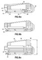
- FIG. 6 b is a side view of the partially expanded interbody fusion device of FIG. 4 .
- FIG. 6 c is a side view of the fully expanded interbody fusion device of FIG. 5 .
- FIG. 7 a is a front view of the unexpanded interbody fusion device of FIG. 1 .
- FIG. 7 b is a front view of the partially expanded interbody fusion device of FIG. 4 .
- FIG. 7 c is a front view of the fully expanded interbody fusion device of FIG. 5 .
- FIG. 8 a is a top view of the unexpanded interbody fusion device of FIG. 1 .
- FIG. 8 b is a top view of the partially expanded interbody fusion device of FIG. 4 .
- FIG. 8 c is a top view of the fully expanded interbody fusion device of FIG. 5 .
- FIG. 9 a is a cross-sectional view of the expandable interbody fusion device of FIG. 8 a as seen along viewing line 9 a - 9 a of FIG. 8 a.
- FIG. 9 b is a cross-sectional view of the expandable interbody fusion device of FIG. 8 b as seen along viewing line 9 b - 9 b of FIG. 8 b.
- FIG. 9 c is a cross-sectional view of the expandable interbody fusion device of FIG. 8 c as seen along viewing line 9 c - 9 c of FIG. 8 c.
- FIG. 10 is a top perspective view of an expandable interbody fusion device in the unexpanded condition, used for a lateral approach, in accordance with alternate embodiment of the present invention.
- FIG. 11 is a top perspective view of the partially expanded interbody fusion device of FIG. 10 .
- FIG. 12 is a top perspective view of the fully expanded interbody fusion device of FIG. 10 .
- an expandable interbody fusion device 10 used for a posterior approach a procedure in which the device 10 is accessed from the back of the spine, is shown.
- the expandable interbody fusion device 10 includes a superior endplate 12 and an inferior endplate 14 .
- the expandable interbody fusion device 10 has a height H between the superior and inferior endplates 12 , 14 in an unexpanded condition as illustrated in FIG. 1 that is less than the normal anatomic height of a typical intradiscal space between opposing vertebral bodies. In this manner, the expandable interbody fusion device 10 may be placed into an intradiscal space and expanded, as described below, to cause distraction of the adjacent vertebral bodies.
- the superior endplate 12 is elongated and comprises a hub 16 and an outer surface 18 .
- the hub includes a pair of side surfaces 20 , 22 extending longitudinally on each side of the hub 16 .
- the hub 16 also includes a pair of end surfaces 24 , 26 extending respectively at the proximal rear end and the distal front end of the superior endplate 12 .
- the hub 16 is dimensioned and configured to be closely accommodated within the inferior endplate 14 for movement in a direction relative to the inferior endplate 14 toward an adjacent vertebral body.
- the superior endplate 12 includes a graft chamber 28 defined by an opening 30 extending through the outer surface 18 and a lower surface 32 of the hub 16 . Opening 30 may be longitudinally centered or situated to lie more adjacent to the proximal or rear end of the device 10 .
- the superior endplate 12 is formed of a biocompatible polymer such as polyethylethylketone (PEEK). PEEK is used in fusion applications for its combination of strength, biocompatibility, and elasticity which is similar to human bone. Other composites may include derivatives of PEEK such as carbon fiber reinforced PEEK and PEKK, respectively.
- the superior endplate 12 may be made of one or more materials having suitable properties for a spinal fusion procedure and the promotion of bone growth, including strength, weight, rigidity, etc.
- the superior endplate 12 may further include an upper endcap that defines the outer surface 18 .
- the endcap may be a separate plate formed of material for the promotion of bone growth, such as titanium, and may be attached to the endplate 12 with suitable conventional techniques.
- the outer surface 18 may be defined by a coating of a suitable layer of bone growth promotion material, such as titanium, which may be deposited by conventional techniques.
- the inferior endplate 14 is elongated and comprises a pair of oppositely spaced apart lateral sidewalls 34 , 36 extending along the longitudinal direction and projecting upwardly from a lower outer surface 38 of the inferior endplate 14 .
- a pair of oppositely spaced apart endwalls 40 , 42 defining an anterior endwall 40 and a posterior endwall 42 , extends laterally across the device 10 and projects upwardly from the lower outer surface 38 .
- Each of the endwalls 40 , 42 includes an upper surface that jointly with an upper surface of sidewalls 34 , 36 defines an upper surface 44 of the inferior endplate 14 . Referring more particularly to FIG.
- the sidewalls 34 , 36 together with the endwalls 40 , 42 form an open, upwardly facing fully bounded interior cavity 48 .
- the interior cavity 48 is dimensioned and configured to closely accommodate the superior endplate 12 in between the sidewalls 34 , 36 and the endwalls 40 , 42 of the inferior endplate 14 in an unexpanded condition.
- the inferior plate 14 as shown in FIGS. 9 a - c defines an insert opening 45 through the posterior endwall 42 of the expandable interbody fusion device 10 through which a series of insertion structures in the form of flat, substantially planar inserts 46 , may be introduced one below the other.
- a plurality of windows 47 may be formed through the sidewalls 34 , 36 as shown in FIGS. 1, 3 and 4-6 c so as to allow visual observation of the expansion of the device 10 and insertion of the series of inserts 46 , which will be described in detail below, by suitable imaging techniques, such as fluoroscopy.
- the inferior endplate 14 includes a graft chamber defined by an opening 50 extending through the lower outer surface 38 and an upper support surface 52 in communication with the interior cavity 48 . Opening 50 is situated to lie at least in partial alignment with the opening 30 in the superior endplate 12 .
- the inferior endplate 12 is formed of a material different from the material of the superior endplate 12 .
- the inferior endplate 12 may be formed of a biocompatible metal, such as titanium, for its strength properties. Titanium is chosen for strength, biocompatibility, processing capability, and fluoroscopic imaging properties (radiolucency).
- inferior endplate 14 is formed of titanium
- the lower outer surface 38 would provide for the promotion of bone growth.
- the inferior endplate 14 is not formed of a bone growth promotion material
- the lower outer surface 38 may be coated with a suitable layer of bone growth promotion material, such as titanium, and deposited in a conventional manner as described hereinabove.
- the inferior endplate 14 could be made of one or more materials having suitable properties for a spinal fusion procedure and the promotion of bone growth, including strength, weight, rigidity, etc.
- the outer surface of the inferior endplate 14 is convex between the lateral sidewalls 34 , 36 .
- inserts 46 may be introduced into the expandable interbody fusion device 10 through insert opening 45 after the superior and inferior endplates 12 , 14 are separated as illustrated in FIGS. 6 a - c , 7 a - c and 9 a - c and the device 10 is expanded incrementally, as more fully described in the '555 application, incorporated herein by reference.
- the height of the device 10 is increased during expansion within the intradiscal space to thereby ultimately restore the normal anatomic height of the disc space.
- Each of inserts 46 may define an opening (not shown) extending therethrough, which is configured to receive a material for promotion of bone growth.
- the outer surface 18 of the superior endplate 12 is formed and bounded by oppositely spaced lateral edges 54 , 56 and oppositely spaced posterior edge 58 and anterior edge 60 .
- the outer surface 18 closer to the anterior edge 60 is configured to be more prominent than the posterior edge 58 .
- the outer surface 18 of the superior endplate 12 defines an anatomic correction surface generally inclining downwardly in an anterior-posterior direction toward the posterior edge 58 .
- the anterior edge 60 may be located higher than the posterior edge 58 .
- a plurality of ridges 62 may be integrally formed on the outer surface 18 , with each of the ridges 62 protruding upwardly.
- the ridges 62 may provide for enhanced engagement with an adjacent vertebral body. It is noted that one or more of the ridges 62 may be more prominent than the anterior edge 60 . In this manner, one or more of the ridges 62 may define an apex of the outer surface 18 . Generally, the outer surface 18 of the superior endplate 14 may be provided with an overall convex shape between the posterior and anterior edges 58 , 60 . In the depicted embodiment, the outer surface 18 is attached to the hub 16 ; alternately, the outer surface 28 may be formed integrally therewith.
- the superior endplate 12 lies fully nested within the bounds of the interior cavity 48 of the inferior endplate 14 .
- the anterior edge 60 of the outer surface 18 of the superior endplate 12 may be located to be substantially flush with, or recessed below, the upper surface 44 of the inferior endplate 14 in the fully nested state of the superior endplate 12 .
- the posterior edge 58 of the outer surface 18 of the superior endplate 12 is recessed within the interior cavity 48 below the upper surface 44 of the inferior endplate 14 with the superior endplate 12 being fully nested.
- the expandable interbody fusion device 10 in an unexpanded state may be provided with a lordotic shape, whereby the distal front portion of the device 10 has a height greater than the proximal rear portion of the device 10 . Furthermore, since the device 10 is lordotic, the unexpanded height of the inferior endplate 14 is defined by the maximum distance M between the lower outer surface 38 and the upper surface 44 of the inferior endplate 14 as illustrated in FIG. 6 a.
- the outer surface 18 of the superior endplate 12 is caused to become proud of the inferior endplate 14 and contact one of two opposing vertebral bodies with the inferior endplate 14 contacting the other vertebral body.
- the expandable interbody fusion device 10 causes the inclination of the outer surface 18 to act against the vertebral endplate.
- the angular disposition may provide a corrective effect to the alignment of the vertebra.
- both the posterior and anterior edges 58 , 60 of the outer surface 18 of the superior endplate 12 move completely out of the interior cavity 48 of the inferior endplate 14 and above the upper surface 44 of the inferior endplate 14 .
- the fully expanded height of the expandable interbody fusion device 10 is defined by the distance D between the lower outer surface 38 of the inferior endplate 14 and the ridge 62 of the superior endplate 12 at the highest point as seen in FIG. 9 c.
- an expandable interbody fusion device 110 used for a lateral approach a procedure in which the device is introduced into the intradiscal space from the side of the spine, is shown.
- the expandable interbody fusion device 110 is elongate and includes a superior endplate 112 and an inferior endplate 114 .
- the expandable interbody fusion device 110 for the lateral approach is structurally similar to the device 10 for a posterior approach.
- the superior endplate 112 includes an outer surface 116 which is formed and bounded by oppositely spaced distal and proximal edges 118 , 120 and a pair of oppositely spaced, longitudinally extending lateral edges, defining a higher lateral edge 122 and a lower lateral edge 124 , extending longitudinally therebetween.
- the outer surface 116 defines an anatomic correction surface generally inclining downwardly in a lateral direction of device 110 toward the lower lateral edge 124 .
- Lower lateral edge 124 is intended during insertion of device 110 to lie adjacent the posterior portion of the disc space with higher lateral edge 122 being adjacent to the anterior portion of the disc space.
- the outer surface 116 of the superior endplate 112 may be convex between the higher and lower lateral edges 122 , 124 and may be convex between the distal and proximal edges 118 , 120 .
- the outer surface of the inferior endplate 114 may be generally convex between lateral sidewalls 128 , 130 and may be convex between distal and proximal sidewalls 132 , 134 .
- the superior endplate 112 is received within the interior cavity of inferior endplate 114 such that the outer surface 116 lies fully nested within the bounds of the interior cavity of inferior endplate 114 .
- at least posterior edge 124 of superior endplate 112 is recessed below the upper surface 126 of inferior endplate 114 .
- Anterior edge 122 may also be recessed below or substantially flush with outer surface 126 .
- Superior endplate 112 is movable in a direction of expansion relative to inferior endplate 114 in a manner as shown in FIG. 11 and as explained hereinabove such that upon expansion at least anterior edge 122 projects outwardly above upper surface 126 of inferior endplate 114 .
- posterior edge 124 projects outwardly above upper surface 126 of inferior endplate 114 and anterior edge 122 is higher than posterior edge 124 .
Abstract
Description
Claims (19)
Priority Applications (1)
| Application Number | Priority Date | Filing Date | Title |
|---|---|---|---|
| US14/741,588 US9498347B2 (en) | 2014-06-25 | 2015-06-17 | Expandable interbody fusion device with nested correction surface |
Applications Claiming Priority (2)
| Application Number | Priority Date | Filing Date | Title |
|---|---|---|---|
| US201462016903P | 2014-06-25 | 2014-06-25 | |
| US14/741,588 US9498347B2 (en) | 2014-06-25 | 2015-06-17 | Expandable interbody fusion device with nested correction surface |
Publications (2)
| Publication Number | Publication Date |
|---|---|
| US20150374509A1 US20150374509A1 (en) | 2015-12-31 |
| US9498347B2 true US9498347B2 (en) | 2016-11-22 |
Family
ID=54929305
Family Applications (1)
| Application Number | Title | Priority Date | Filing Date |
|---|---|---|---|
| US14/741,588 Active US9498347B2 (en) | 2014-06-25 | 2015-06-17 | Expandable interbody fusion device with nested correction surface |
Country Status (2)
| Country | Link |
|---|---|
| US (1) | US9498347B2 (en) |
| WO (1) | WO2015200058A1 (en) |
Cited By (8)
| Publication number | Priority date | Publication date | Assignee | Title |
|---|---|---|---|---|
| US10179054B2 (en) | 2008-02-06 | 2019-01-15 | Jeffrey B. Kleiner | Spinal fusion cage system with inserter |
| US10195053B2 (en) | 2009-09-18 | 2019-02-05 | Spinal Surgical Strategies, Llc | Bone graft delivery system and method for using same |
| US10201355B2 (en) | 2009-02-06 | 2019-02-12 | Kleiner Intellectual Property, Llc | Angled surgical tool for removing tissue from within an intervertebral space |
| US10245159B1 (en) | 2009-09-18 | 2019-04-02 | Spinal Surgical Strategies, Llc | Bone graft delivery system and method for using same |
| US10786367B2 (en) * | 2016-07-21 | 2020-09-29 | Seaspine, Inc. | Expandable implant |
| US10973656B2 (en) | 2009-09-18 | 2021-04-13 | Spinal Surgical Strategies, Inc. | Bone graft delivery system and method for using same |
| US11013610B2 (en) | 2017-10-18 | 2021-05-25 | Spine Wave, Inc. | Expandable anterior lumbar interbody fusion device |
| US11666455B2 (en) | 2009-09-18 | 2023-06-06 | Spinal Surgical Strategies, Inc., A Nevada Corporation | Bone graft delivery devices, systems and kits |
Families Citing this family (17)
| Publication number | Priority date | Publication date | Assignee | Title |
|---|---|---|---|---|
| US8597360B2 (en) | 2004-11-03 | 2013-12-03 | Neuropro Technologies, Inc. | Bone fusion device |
| US9265620B2 (en) | 2011-03-18 | 2016-02-23 | Raed M. Ali, M.D., Inc. | Devices and methods for transpedicular stabilization of the spine |
| EP2685921B1 (en) | 2011-03-18 | 2019-03-13 | Raed M. Ali, M.D., Inc. | Transpedicular access to intervertebral spaces and related spinal fusion systems and methods |
| WO2013023096A1 (en) | 2011-08-09 | 2013-02-14 | Neuropro Technologies, Inc. | Bone fusion device, system and method |
| US10420654B2 (en) | 2011-08-09 | 2019-09-24 | Neuropro Technologies, Inc. | Bone fusion device, system and method |
| WO2013023098A1 (en) | 2011-08-09 | 2013-02-14 | Neuropro Spinal Jaxx Inc. | Bone fusion device, apparatus and method |
| US9532883B2 (en) | 2012-04-13 | 2017-01-03 | Neuropro Technologies, Inc. | Bone fusion device |
| US10159583B2 (en) | 2012-04-13 | 2018-12-25 | Neuropro Technologies, Inc. | Bone fusion device |
| US9861495B2 (en) | 2013-03-14 | 2018-01-09 | Raed M. Ali, M.D., Inc. | Lateral interbody fusion devices, systems and methods |
| US10098757B2 (en) | 2013-03-15 | 2018-10-16 | Neuropro Technologies Inc. | Bodiless bone fusion device, apparatus and method |
| US10111760B2 (en) | 2017-01-18 | 2018-10-30 | Neuropro Technologies, Inc. | Bone fusion system, device and method including a measuring mechanism |
| US10973657B2 (en) | 2017-01-18 | 2021-04-13 | Neuropro Technologies, Inc. | Bone fusion surgical system and method |
| US10729560B2 (en) | 2017-01-18 | 2020-08-04 | Neuropro Technologies, Inc. | Bone fusion system, device and method including an insertion instrument |
| US10213321B2 (en) | 2017-01-18 | 2019-02-26 | Neuropro Technologies, Inc. | Bone fusion system, device and method including delivery apparatus |
| WO2018136304A1 (en) * | 2017-01-18 | 2018-07-26 | Neuropro Technologies, Inc. | Bone fusion device, system and method |
| US10881524B2 (en) | 2018-03-06 | 2021-01-05 | Eit Emerging Implant Technologies Gmbh | Angularly adjustable intervertebral cages with integrated ratchet assembly |
| US11291559B1 (en) * | 2021-03-05 | 2022-04-05 | CTL Amedica Corporation | Expandable interbody fusion device and method of manufacturing the same |
Citations (23)
| Publication number | Priority date | Publication date | Assignee | Title |
|---|---|---|---|---|
| US6176882B1 (en) * | 1998-02-20 | 2001-01-23 | Biedermann Motech Gmbh | Intervertebral implant |
| US6193757B1 (en) | 1998-10-29 | 2001-02-27 | Sdgi Holdings, Inc. | Expandable intervertebral spacers |
| US6436140B1 (en) | 1998-08-28 | 2002-08-20 | Sofamor S.N.C. | Expandable interbody fusion cage and method for insertion |
| US6595998B2 (en) | 2001-03-08 | 2003-07-22 | Spinewave, Inc. | Tissue distraction device |
| US20040162618A1 (en) | 2003-02-14 | 2004-08-19 | Centerpulse Spine-Tech, Inc. | Expandable intervertebral implant cage |
| US6830589B2 (en) | 1999-06-23 | 2004-12-14 | Zimmer Spine, Inc. | Expandable fusion device and method |
| US20080147193A1 (en) * | 2006-11-23 | 2008-06-19 | Wilfried Matthis | Expandable intervertebral implant |
| US7618459B2 (en) | 2005-09-26 | 2009-11-17 | Infinity Orthopedics Ltd. | Universal spinal disc implant system |
| US20100286779A1 (en) | 2009-05-06 | 2010-11-11 | Thibodeau Lee L | Expandable spinal implant apparatus and method of use |
| US7931688B2 (en) | 2004-08-25 | 2011-04-26 | Spine Wave, Inc. | Expandable interbody fusion device |
| US7967867B2 (en) | 2007-05-31 | 2011-06-28 | Spine Wave, Inc. | Expandable interbody fusion device |
| US8480748B2 (en) | 2010-10-07 | 2013-07-09 | Nicholas Poulos | Lordotic expandable interbody implant and method |
| US20130211525A1 (en) * | 2011-08-09 | 2013-08-15 | Gary R. McLuen | Bone fusion device, apparatus and method |
| US20130274883A1 (en) * | 2012-04-13 | 2013-10-17 | Gary R. McLuen | Bone fusion device |
| US8628576B2 (en) | 2011-02-14 | 2014-01-14 | Imds Corporation | Expandable intervertebral implants and instruments |
| US8685098B2 (en) | 2010-06-25 | 2014-04-01 | Globus Medical, Inc. | Expandable fusion device and method of installation thereof |
| US20140100662A1 (en) | 2012-10-09 | 2014-04-10 | Titan Spine, Llc | Expandable spinal implant with expansion wedge and anchor |
| US8715351B1 (en) | 2012-11-29 | 2014-05-06 | Spine Wave, Inc. | Expandable interbody fusion device with graft chambers |
| US20140236296A1 (en) * | 2013-02-20 | 2014-08-21 | Erik Wagner | Expandable fusion device for positioning between adjacent vertebral bodies |
| US8900312B2 (en) | 2013-03-12 | 2014-12-02 | Spine Wave, Inc. | Expandable interbody fusion device with graft chambers |
| US20150012097A1 (en) * | 2013-07-03 | 2015-01-08 | Spinefrontier Inc | System amd method for an expandable intervertebral implant |
| US20150190242A1 (en) * | 2013-12-05 | 2015-07-09 | Spinal Elements, Inc. | Expandable interbody device |
| US9084686B1 (en) * | 2014-03-06 | 2015-07-21 | Spine Wave, Inc. | Inserter for an expandable spinal interbody fusion device |
-
2015
- 2015-06-17 WO PCT/US2015/036132 patent/WO2015200058A1/en active Application Filing
- 2015-06-17 US US14/741,588 patent/US9498347B2/en active Active
Patent Citations (24)
| Publication number | Priority date | Publication date | Assignee | Title |
|---|---|---|---|---|
| US6176882B1 (en) * | 1998-02-20 | 2001-01-23 | Biedermann Motech Gmbh | Intervertebral implant |
| US6436140B1 (en) | 1998-08-28 | 2002-08-20 | Sofamor S.N.C. | Expandable interbody fusion cage and method for insertion |
| US6193757B1 (en) | 1998-10-29 | 2001-02-27 | Sdgi Holdings, Inc. | Expandable intervertebral spacers |
| US6830589B2 (en) | 1999-06-23 | 2004-12-14 | Zimmer Spine, Inc. | Expandable fusion device and method |
| US6595998B2 (en) | 2001-03-08 | 2003-07-22 | Spinewave, Inc. | Tissue distraction device |
| US20040162618A1 (en) | 2003-02-14 | 2004-08-19 | Centerpulse Spine-Tech, Inc. | Expandable intervertebral implant cage |
| US7931688B2 (en) | 2004-08-25 | 2011-04-26 | Spine Wave, Inc. | Expandable interbody fusion device |
| US7618459B2 (en) | 2005-09-26 | 2009-11-17 | Infinity Orthopedics Ltd. | Universal spinal disc implant system |
| US20080147193A1 (en) * | 2006-11-23 | 2008-06-19 | Wilfried Matthis | Expandable intervertebral implant |
| US7967867B2 (en) | 2007-05-31 | 2011-06-28 | Spine Wave, Inc. | Expandable interbody fusion device |
| US20100286779A1 (en) | 2009-05-06 | 2010-11-11 | Thibodeau Lee L | Expandable spinal implant apparatus and method of use |
| US8685098B2 (en) | 2010-06-25 | 2014-04-01 | Globus Medical, Inc. | Expandable fusion device and method of installation thereof |
| US8480748B2 (en) | 2010-10-07 | 2013-07-09 | Nicholas Poulos | Lordotic expandable interbody implant and method |
| US8628576B2 (en) | 2011-02-14 | 2014-01-14 | Imds Corporation | Expandable intervertebral implants and instruments |
| US20130211525A1 (en) * | 2011-08-09 | 2013-08-15 | Gary R. McLuen | Bone fusion device, apparatus and method |
| US20130274883A1 (en) * | 2012-04-13 | 2013-10-17 | Gary R. McLuen | Bone fusion device |
| US20140100662A1 (en) | 2012-10-09 | 2014-04-10 | Titan Spine, Llc | Expandable spinal implant with expansion wedge and anchor |
| US8715351B1 (en) | 2012-11-29 | 2014-05-06 | Spine Wave, Inc. | Expandable interbody fusion device with graft chambers |
| US20140148903A1 (en) | 2012-11-29 | 2014-05-29 | Spine Wave, Inc. | Expandable interbody fusion device with graft chambers |
| US20140236296A1 (en) * | 2013-02-20 | 2014-08-21 | Erik Wagner | Expandable fusion device for positioning between adjacent vertebral bodies |
| US8900312B2 (en) | 2013-03-12 | 2014-12-02 | Spine Wave, Inc. | Expandable interbody fusion device with graft chambers |
| US20150012097A1 (en) * | 2013-07-03 | 2015-01-08 | Spinefrontier Inc | System amd method for an expandable intervertebral implant |
| US20150190242A1 (en) * | 2013-12-05 | 2015-07-09 | Spinal Elements, Inc. | Expandable interbody device |
| US9084686B1 (en) * | 2014-03-06 | 2015-07-21 | Spine Wave, Inc. | Inserter for an expandable spinal interbody fusion device |
Non-Patent Citations (1)
| Title |
|---|
| PCT Search Report and Written Opinion for PCT/US2015/036132, dated Sep. 16, 2015. |
Cited By (10)
| Publication number | Priority date | Publication date | Assignee | Title |
|---|---|---|---|---|
| US10179054B2 (en) | 2008-02-06 | 2019-01-15 | Jeffrey B. Kleiner | Spinal fusion cage system with inserter |
| US10201355B2 (en) | 2009-02-06 | 2019-02-12 | Kleiner Intellectual Property, Llc | Angled surgical tool for removing tissue from within an intervertebral space |
| US10195053B2 (en) | 2009-09-18 | 2019-02-05 | Spinal Surgical Strategies, Llc | Bone graft delivery system and method for using same |
| US10245159B1 (en) | 2009-09-18 | 2019-04-02 | Spinal Surgical Strategies, Llc | Bone graft delivery system and method for using same |
| US10973656B2 (en) | 2009-09-18 | 2021-04-13 | Spinal Surgical Strategies, Inc. | Bone graft delivery system and method for using same |
| US11660208B2 (en) | 2009-09-18 | 2023-05-30 | Spinal Surgical Strategies, Inc. | Bone graft delivery system and method for using same |
| US11666455B2 (en) | 2009-09-18 | 2023-06-06 | Spinal Surgical Strategies, Inc., A Nevada Corporation | Bone graft delivery devices, systems and kits |
| US10786367B2 (en) * | 2016-07-21 | 2020-09-29 | Seaspine, Inc. | Expandable implant |
| US11806248B2 (en) | 2016-07-21 | 2023-11-07 | Seaspine, Inc. | Expandable implant |
| US11013610B2 (en) | 2017-10-18 | 2021-05-25 | Spine Wave, Inc. | Expandable anterior lumbar interbody fusion device |
Also Published As
| Publication number | Publication date |
|---|---|
| US20150374509A1 (en) | 2015-12-31 |
| WO2015200058A1 (en) | 2015-12-30 |
Similar Documents
| Publication | Publication Date | Title |
|---|---|---|
| US9498347B2 (en) | Expandable interbody fusion device with nested correction surface | |
| US20230181332A1 (en) | Expandable and angularly adjustable intervertebral cages with articulating joint | |
| US10555818B2 (en) | Spinal fusion implant for oblique insertion | |
| US11752006B2 (en) | Angularly adjustable intervertebral cages with integrated ratchet assembly | |
| US8480748B2 (en) | Lordotic expandable interbody implant and method | |
| US9517140B2 (en) | Apparatus for use in spinal interbody fusion | |
| US7326251B2 (en) | Interbody fusion device | |
| US8425608B2 (en) | Lordotic expanding vertebral body spacer | |
| US7137997B2 (en) | Spinal fusion implant | |
| US7862618B2 (en) | Expandable vertebral body implants and methods of use | |
| US11382761B2 (en) | Expandable interbody spacer | |
| US20110190889A1 (en) | Lordotic interbody device with different sizes rails | |
| CN111712218A (en) | Modular adjustable centrum resection fusion cage | |
| US11701241B2 (en) | Bellows shaped spinal implant |
Legal Events
| Date | Code | Title | Description |
|---|---|---|---|
| AS | Assignment |
Owner name: SPINE WAVE, INC., CONNECTICUT Free format text: ASSIGNMENT OF ASSIGNORS INTEREST;ASSIGNOR:MCLEAN, SCOTT;REEL/FRAME:035850/0704 Effective date: 20150616 |
|
| STCF | Information on status: patent grant |
Free format text: PATENTED CASE |
|
| AS | Assignment |
Owner name: SILICON VALLEY BANK, MASSACHUSETTS Free format text: SECURITY INTEREST;ASSIGNOR:SPINE WAVE, INC.;REEL/FRAME:046612/0765 Effective date: 20180719 Owner name: OXFORD FINANCE LLC, VIRGINIA Free format text: SECURITY INTEREST;ASSIGNOR:SPINE WAVE, INC.;REEL/FRAME:046612/0765 Effective date: 20180719 |
|
| MAFP | Maintenance fee payment |
Free format text: PAYMENT OF MAINTENANCE FEE, 4TH YR, SMALL ENTITY (ORIGINAL EVENT CODE: M2551); ENTITY STATUS OF PATENT OWNER: SMALL ENTITY Year of fee payment: 4 |
|
| AS | Assignment |
Owner name: SILICON VALLEY BANK, MASSACHUSETTS Free format text: SECURITY INTEREST;ASSIGNOR:SPINE WAVE, INC.;REEL/FRAME:062886/0507 Effective date: 20230228 |