US9497160B1 - Symmetric NAT traversal for direct communication in P2P networks when some of the routing NATs are symmetric - Google Patents
Symmetric NAT traversal for direct communication in P2P networks when some of the routing NATs are symmetric Download PDFInfo
- Publication number
- US9497160B1 US9497160B1 US13/925,796 US201313925796A US9497160B1 US 9497160 B1 US9497160 B1 US 9497160B1 US 201313925796 A US201313925796 A US 201313925796A US 9497160 B1 US9497160 B1 US 9497160B1
- Authority
- US
- United States
- Prior art keywords
- client
- packets
- nat
- sent
- port
- Prior art date
- Legal status (The legal status is an assumption and is not a legal conclusion. Google has not performed a legal analysis and makes no representation as to the accuracy of the status listed.)
- Expired - Fee Related, expires
Links
Images


Classifications
-
- H—ELECTRICITY
- H04—ELECTRIC COMMUNICATION TECHNIQUE
- H04L—TRANSMISSION OF DIGITAL INFORMATION, e.g. TELEGRAPHIC COMMUNICATION
- H04L61/00—Network arrangements, protocols or services for addressing or naming
- H04L61/09—Mapping addresses
- H04L61/25—Mapping addresses of the same type
-
- H04L29/12471—
-
- H—ELECTRICITY
- H04—ELECTRIC COMMUNICATION TECHNIQUE
- H04L—TRANSMISSION OF DIGITAL INFORMATION, e.g. TELEGRAPHIC COMMUNICATION
- H04L61/00—Network arrangements, protocols or services for addressing or naming
- H04L61/09—Mapping addresses
- H04L61/25—Mapping addresses of the same type
- H04L61/2503—Translation of Internet protocol [IP] addresses
- H04L61/2521—Translation architectures other than single NAT servers
-
- H—ELECTRICITY
- H04—ELECTRIC COMMUNICATION TECHNIQUE
- H04L—TRANSMISSION OF DIGITAL INFORMATION, e.g. TELEGRAPHIC COMMUNICATION
- H04L61/00—Network arrangements, protocols or services for addressing or naming
- H04L61/09—Mapping addresses
- H04L61/25—Mapping addresses of the same type
- H04L61/2503—Translation of Internet protocol [IP] addresses
- H04L61/255—Maintenance or indexing of mapping tables
- H04L61/2553—Binding renewal aspects, e.g. using keep-alive messages
-
- H—ELECTRICITY
- H04—ELECTRIC COMMUNICATION TECHNIQUE
- H04L—TRANSMISSION OF DIGITAL INFORMATION, e.g. TELEGRAPHIC COMMUNICATION
- H04L61/00—Network arrangements, protocols or services for addressing or naming
- H04L61/09—Mapping addresses
- H04L61/25—Mapping addresses of the same type
- H04L61/2503—Translation of Internet protocol [IP] addresses
- H04L61/256—NAT traversal
- H04L61/2567—NAT traversal for reachability, e.g. inquiring the address of a correspondent behind a NAT server
-
- H—ELECTRICITY
- H04—ELECTRIC COMMUNICATION TECHNIQUE
- H04L—TRANSMISSION OF DIGITAL INFORMATION, e.g. TELEGRAPHIC COMMUNICATION
- H04L61/00—Network arrangements, protocols or services for addressing or naming
- H04L61/09—Mapping addresses
- H04L61/25—Mapping addresses of the same type
- H04L61/2503—Translation of Internet protocol [IP] addresses
- H04L61/256—NAT traversal
- H04L61/2575—NAT traversal using address mapping retrieval, e.g. simple traversal of user datagram protocol through session traversal utilities for NAT [STUN]
-
- H—ELECTRICITY
- H04—ELECTRIC COMMUNICATION TECHNIQUE
- H04L—TRANSMISSION OF DIGITAL INFORMATION, e.g. TELEGRAPHIC COMMUNICATION
- H04L61/00—Network arrangements, protocols or services for addressing or naming
- H04L61/09—Mapping addresses
- H04L61/25—Mapping addresses of the same type
- H04L61/2503—Translation of Internet protocol [IP] addresses
- H04L61/2514—Translation of Internet protocol [IP] addresses between local and global IP addresses
Definitions
- the present disclosure relates to networking and particularly to peer-to-peer (P2P) traffic processing technologies and network address translator (NAT) traversal methods.
- P2P peer-to-peer
- NAT network address translator
- the disclosed NAT traversal methods relate to establishing direct connections to clients behind symmetrical NATs and asymmetrical NATs.
- IPv4 One currently used Internet protocol, IPv4, was originally designed to use a 32-bit address field (IP address) to identify a host. A 32-bit IP address is insufficient to assign a global (or public) IP address to each device on the Internet today.
- Border routers started performing a new and important networking task: translating (mapping) IP addresses between the private and the public domains, thus allowing a host within a local network to be able to communicate 2-way globally even though it has a local (private) IP address only. Border routers also hid their local network visibility from the outside, which turned out to be quite helpful for the security and protection of the isolated local networks. Due to this property, Border Routers also became firewalls.
- NATs Network Address Translators
- IPv6 is a protocol designed to address the IPv4 address shortage problem.
- the computing world may still continue to deploy NATs in order to isolate private enterprise and home networks from external visibility.
- NATs are not required to be compatible with each other such as in the way that NATs generate their IP address translations.
- NATs are manufactured by different OEMs, and not only differ from vendor to vendor but even from model to model.
- the history of NATs has generated an unpleasant side effect, which has become a serious issue and obstacle for many Internet applications: NATs break the end-to-end connectivity of devices and applications by often not allowing the establishment of peer-to-peer (P2P) communications. Almost all NATs block and reject the data transmitted directly between end-points from different private networks.
- P2P peer-to-peer
- VoIP voice over IP
- multimedia over IP including Streaming Live A/V or Real-Time Interactive A/V
- videoconference instant messaging online gaming and even online gambling, et al.
- NATs unwanted check points on the communication path.
- the presence of NATs is a limiting factor in the development of P2P applications especially in mobile wireless networks.
- Embodiments, implementations and techniques described herein include systems, apparatuses and methods for facilitating connection between two or more clients across a network that includes NATs.
- the techniques include peer-to-peer (P2P) traffic processing and network address translator (NAT) traversal.
- P2P peer-to-peer
- NAT network address translator
- the techniques involve direct NAT traversal techniques for clients behind NATs.
- the techniques can establish direct connections between clients located in private networks behind NATs.
- the connection can be established indirectly via a non-Symmetric NAT (used as a relay) which establishes connection with both Symmetric NATs using the proposed direct connection techniques.
- FIG. 1 is a flowchart for detecting NAT types for clients seeking to connect across a public/private network according to one implementation.
- FIG. 2 is a pseudo-code listing for NAT type detecting according to one implementation.
- FIG. 3 is a schematic representation for connecting clients that are each behind a Type B (non-symmetric) NAT according to one implementation.
- FIG. 4 is a schematic representation for connecting clients when one of the clients is behind a Type A (symmetric) NAT according to one implementation.
- FIG. 5A is a first portion of a flowchart from the perspective of a first client when one of the clients is behind a Type A (symmetric) NAT according to one implementation.
- FIG. 5B is a second portion of a flowchart from the perspective of a first client when one of the clients is behind a Type A (symmetric) NAT according to one implementation.
- FIG. 5C is a third portion of a flowchart from the perspective of a first client when one of the clients is behind a Type A (symmetric) NAT according to one implementation.
- FIG. 6A is a first portion of a flowchart from the perspective of a second client when one of the clients is behind a Type A (symmetric) NAT according to one implementation.
- FIG. 6B is a second portion of a flowchart from the perspective of a second client when one of the clients is behind a Type A (symmetric) NAT according to one implementation.
- FIG. 6C is a third portion of a flowchart from the perspective of a second client when one of the clients is behind a Type A (symmetric) NAT according to one implementation.
- FIG. 7 is a flowchart showing a Type A and Type B NAT traversal method according to one implementation.
- FIG. 8 is a pseudo-code listing or algorithm of a dynamic programming method for optimal partitioning of M into S number of terms.
- FIG. 9A is a table showing generated values from various scenarios of starting values for the traversal method according to one implementation.
- FIG. 9B is a table showing generated IP addresses and port numbers based on the generated values of FIG. 9A according to one implementation for divergent packets originating from client B.
- FIG. 9C is a table showing generated IP addresses and port numbers based on the generated values of FIG. 9A according to one implementation for convergent packets originating from client A.
- FIG. 10 is another table showing generated values from other scenarios of starting values for the traversal method according to one implementation.
- FIG. 11 is a pseudo-code listing or algorithm for detection of Symmetric NATs using a server according to one implementation.
- FIG. 12 is a pseudo-code listing or set of algorithms illustrating use of Symmetric NAT detection according to one implementation.
- FIG. 13 is a pseudo-code listing or set of algorithms illustrating steps to be taken by clients behind either a non-Symmetric or Symmetric NAT type according to one implementation.
- FIG. 14 is another pseudo-code listing or set of algorithms illustrating making a connection between clients according to one implementation.
- FIG. 15 is another pseudo-code listing or set of algorithms further illustrating making a connection between clients according to one implementation.
- FIG. 16 shows an example of a network topology across which two or more clients may establish direct communications according to one implementation.
- FIG. 17 shows an example of hardware that may be used to implement the techniques described herein according to one implementation.
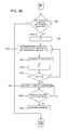
- FIG. 18A is a first portion of a flowchart from the perspective of a first client without the use of NAT detection according to one implementation.
- FIG. 18B is a second portion of a flowchart from the perspective of a first client without the use of NAT detection according to one implementation.
- FIG. 18C is a third portion of a flowchart from the perspective of a first client without the use of NAT detection according to one implementation.
- FIG. 19A is a first portion of a flowchart from the perspective of a second client without the use of NAT detection according to one implementation.
- FIG. 19B is a second portion of a flowchart from the perspective of a second client without the use of NAT detection according to one implementation.
- FIG. 19C is a third portion of a flowchart from the perspective of a second client without the use of NAT detection according to one implementation.
- NAT traversal is an important problem in the computer industry and this disclosure addresses solutions to this problem.
- teachings for setting up a direct (i.e., with and without an initial server intervention, but no subsequent relaying of) P2P communication path are teachings for setting up a direct (i.e., with and without an initial server intervention, but no subsequent relaying of) P2P communication path.
- NAT Described immediately below are descriptions and classifications of NATs. One substantive distinction is whether the NAT is symmetric or not. Other distinctions include the following.
- NAT Full-cone NAT or one-to-one NAT.
- This NAT operates such that once an internal address (iAddr:iPort) is mapped to an external address (eAddr:ePort), any packets from iAddr:iPort are sent through eAddr:ePort. Any external host can send packets to iAddr:iPort by sending packets to eAddr:ePort.
- Address-restricted-cone NAT operates such that once an internal address (iAddr:iPort) is mapped to an external address (eAddr:ePort), any packets from iAddr:iPort are sent through eAddr:ePort.
- An external host hAddr:any
- Port-restricted cone NAT This NAT is like an address restricted cone NAT, but the restriction includes port numbers.
- iAddr:iPort Once an internal address (iAddr:iPort) is mapped to an external address (eAddr:ePort), any packets from iAddr:iPort are sent through eAddr:ePort.
- An external host hAddr:hPort can send packets to iAddr:iPort by sending packets to eAddr:ePort only if iAddr:iPort has previously sent a packet to hAddr:hPort.
- Symmetric NAT Each request from the same internal IP address and port to a specific destination IP address and port is mapped to a unique external source IP address and port. If the same internal host sends a packet even with the same source address and port but to a different destination, a different mapping is used. Only an external host that receives a packet from an internal host can send a packet back.
- an (Addr:Port) pair i.e., an IP address and port number
- Every TCP and UDP packet contains both a source socket as well as a destination socket.
- a variable may be listed as a “cone NAT”, but is merely a variable to refer to a non-symmetric NAT.
- cone NAT is in reference to the cases where a detection algorithm outcome determines that a client is not behind a Symmetric NAT.
- NATs control connections between the public and the private domains by creating and updating connections in a table.
- Each entry (called a binding) of the table contains the internal socket (i.e., internal IP address and port number) and external NAT socket, where NAT replaces the internal (private) address with its global IP address and map the internal port number to some external port number, according to the NAT type and a port binding strategy in use.
- Symmetric NATs do not reuse ports for multiple connections.
- the NAT classification can be also clarified and described as follows.
- a packet sent from an internal address (iAddr:iPort) to an external host (hAddr:hPort) and internal address (iAddr:iPort) is mapped (by a NAT) to an external address (eAddr:ePort), that is iAddr:iPort and will be sent through eAddr:ePort of the NAT.
- iAddr:iPort internal address
- eAddr:ePort an external address
- the NAT classification can be characterized in the following way (note the first bullets in the first 3 NAT types are the same).
- STUN Simple Traversal of UDP through NATs. STUN is used for communication between a client and a server. STUN cannot support traversal of Symmetric NATs. STUN works well only in the case of traversing a full cone NAT.
- the RFC for STUN can found at: http://tools.iettorg/html/rfc5389
- TURN Traversal Using Relay NAT.
- TURN uses a relay server which requires a high data bandwidth expense and is impractical for scaling to a large number of clients and requires data intensive P2P communications.
- the RFC for TURN can found at: http://tools.ietf.org/html/rfc5766
- ICE Interactive Connectivity Establishment
- ICE uses a framework defining how to combine STUN and TURN to establish a P2P connection.
- the disadvantages of the STUN and TURN protocols apply.
- the RFC for ICE can be found at http://tools.ietf.org/html/rfc5245
- UPnP Universal Plug and Play
- DMZ Demilitarized Zone
- Proprietary solutions e.g., Skype®, Viber®, Teredo tunneling
- Skype® Voice®
- Viber® Teredo tunneling
- Many proprietary solutions fail to provide connectivity due to a lack of universal deployment.
- Previously used (known) protocols need to be backed up by TURN-like sessions in a separate relay server for communication, which implies a massive intervention of a server and large network bandwidth used from the relaying server.
- the presence of a Symmetric NAT on the data path forces the necessity of relaying via a server.
- Techniques described herein assist in avoiding relaying via a server. Relaying via a server is inefficient, generally requires high performance servers, and involves non-optimal network use. Reversal connections work only when one of the clients is located behind a NAT. Hole punching only works when there are no Symmetric NATs on the path between peers. Port number (port binding) Prediction is not reliable and is not suitable for Symmetric NATs with random port binding.
- the techniques described herein provide solutions that address the above-referenced problems. These techniques include new low cost traffic processing. Minimal server interaction is needed.
- disclosed herein are direct NAT traversal methods for clients behind NATs. Described is how to establish a connection between clients located in private networks behind NATs. It is noted that the techniques may not be computationally advantageous in making connections in the relatively rare case when the clients are each behind a Symmetric NAT.
- a server may be communicate: (1) to a first client whether the first client and a second client are both available for a connection, (2) to the first client and/or the second client IP addresses to use for attempting a connection, and (3) a start signal for the first client and second client to begin attempting to establish a connection.
- the start signal sent to the first client may be sent at a substantially same time as the start signal sent to the second client.
- the start signal sent to each respective client may be sent at different times.
- the start signal or command may include a timestamp at a present time or future time at which to begin the connection attempt.
- the timestamp value may be based on one or more factors. Such factors may include an actual or estimated network latency, an alarm set by one or more devices or the server, and a time set by one or more of the clients that are attempting connection with each other. Two or more clients or applications may attempt to connect with each other at the same time, or in some sequence.
- the techniques described herein include direct NAT traversal methods to establish one or more network connections: (1) between clients located in distinct private networks, each behind one or more NATs and where at least one NAT is not a Symmetric NAT in the chain of NATs between the client in question and a public network such as the Internet; and (2) if desired, for multiple clients, simultaneous establishment of two or more connections to a particular or originating client.
- NAT traversal methods described herein include: (1) selection of particular algorithms and their parameters (“scenarios”), and (2) practical optimization, validation, and testing of the NAT traversal scenario.
- a first method involves performing a NAT type detection.
- a second method does not perform NAT type detection before proceeding with attempting establishment of a connection between clients.
- Some of the steps performed herein, such as ones that rely on NAT type detection, may bear some analogy with STUN.
- STUN there are substantial and substantive distinctions.
- one method economically detects and classifies one or more NATs in the network pathway according to a simple taxonomy, such as dividing the detected NATs as: “Symmetric NAT” or “All Other NATs.”
- Symmetric NATs are referred to as Type A NATs, and all others as Type B NATs.
- Type B NATs may be referred to as CONE NATs for sake of contrast to Type A NATs.
- a common and useful case occurs when a user desires to establish a connection between a client that is behind a Type A NAT and a client behind a Type B NAT.
- the techniques described herein also function when the clients are each behind a Type B NAT.
- NAT type detection includes creating (by a client) a listen socket 102 on a client device.
- the client sends one or more packets from a local address (e.g., via a local NAT) to a server 104 .
- This server is designated and made available for the purpose of NAT type detection.
- the server receives the packet(s) at a pre-arranged, pre-designated or already known IP address and port.
- the client receives one or more packets from the server on or from the designated port at step 106 .
- the one or more packets include the client's NAT address and NAT port information.
- a client sends one or more packets from the local address and client port (a socket) to a second server IP address and server port (a second socket).
- the originating client receives one or more packets from the server from the second server socket (second server IP address and server port).
- the client obtains a NAT address and port.
- the first client investigates to determine if the ports from the two sockets are the same. If so, at step 114 , the NAT type is a CONE NAT. Otherwise, at step 116 , the NAT type is a Symmetric NAT (Type A). This process can also be described as follows. Two Clients connect to a server. The server tests each client and tells each client whether it is associated with a Symmetric NAT (Type A) or not (Type B).
- the server also gives each client the IP address and port of the other client's NAT, the NAT associated with the respective client that is closest to the server.
- the Client or clients send to destination ports 50000 and 50001 from source port 40000.
- the server listens to ports 50000 and 50001. If the source port of the packet (as seen by the server) from destination 50000 is equal to the source port received from 50001, then this client becomes “Client Type B”.
- the actual source port number that matches between the two packets received by the server is saved as EXT_SRC_PORT_B and sent to both Clients. Otherwise the client under test becomes “Client Type A”.
- the server tells the client under test its Client Type and the visible IP addresses and port of the other client.
- the described communicative steps such as sending packets between particular ports of the clients and server may be achieved via one or more particular settings. For example, other ports may be selected, or other number of ports may be involved, etc. For example, three, four or fifty ports may be involved.
- FIG. 2 An example of a NAT type detection method is also described in FIG. 2 in pseudo code.
- the individual steps are not described here in the Specification, as the steps of the pseudo code are self-explanatory.
- There are two sets of pseudo code in FIG. 2 a first set directed to pseudo code, steps or instructions that operate on a server, and a second set directed to pseudo code, steps or instructions that operate on a client.
- Such client uses the server to determine a NAT type between the client and the server.
- General NAT traversal method This section describes a general or generic NAT traversal method that can be applied to the case when a client is behind a NAT of Type A (i.e., Symmetric NAT with true random mapping of internal IP addresses and ports of the clients behind that Symmetric NAT). Algorithms, instructions and computer executable code implementing this method establish a connection between clients behind NATs where previously known methods, algorithms and protocols fail.
- Type A i.e., Symmetric NAT with true random mapping of internal IP addresses and ports of the clients behind that Symmetric NAT.
- send and receive packets means at least UDP over IP. But for a person of ordinary skill it is possible to extend the proposed methods and algorithms to other protocols (e.g., TCP, ICMP).
- the first case involves the technically easy case when both NATs are of Type B. Making a connection between clients B, A in this case is straight forward provided both binding port pairs are known: (pB, EXT_POPT_B) for NAT B and (pA, EXT_POPT_A) for NAT A, respectively.
- This method is illustrated in FIG. 3 .
- a client operating on a first device 302 connects with a client operating on a second device 304 through its NAT 306 and through the NAT 308 of the second device 304 .
- One or more packets are sent from the source port pB to destination port EXT_SRC_PORT_A.
- One or more packets are sent from the source port pA to destination port EXT_SRC_PORT_B.
- a connection is established by having one or both clients send information from source port 40000 to the IP address and binding port of the other client, and having one or both clients 302 , 304 listen to port 40000.
- a reply is sent to the listen port 40000 and thus a connection 310 is established.
- the first client is behind a Type B NAT (second scenario) or the second client is behind a Type B NAT (third scenario).
- a bag contains N balls; initially the balls are unmarked.
- One person B selects M of the balls, then marks each of the selected M balls with a mark and puts them back into the bag.
- a person A retrieves k[1] balls, marks them with her own mark and does not return the selected and marked balls to the bag. If at least one ball has two marks (one mark from person A and one mark from person B), the process is finished—a connection is made. Otherwise, gets k[2] more balls are selected by person A, and person A marks the selected balls with her mark; she does not return the selected balls to the bag. After retrieving k[2] number of balls, if at least one of the selected balls has two marks (from person A and person B), the process is finished—a connection is made.
- This process of selecting balls by person A can be repeated until a ball with 2 marks is obtained.
- the repeating can be represented as further steps of k[3], k[4], . . . , k[S] balls, where the number of steps, S, is a predefined or calculated value or parameter. That is, the process is repeated, as needed, a certain number of times.
- the retrieval of balls is analogous to sending packets and marking a ball with two marks is analogous to finding information that can lead to an established connection between person A and person B.
- the withdrawing by persons A and B may be done independently of each other—i.e., in any order without regard for the actions of the other person.
- each “ball” may be one or a plurality of packets (a “salvo” of packets).
- each “ball” may be associated with a time to live or TTL such as a short or long TTL.
- TTL time to live
- each salvo may be sent with either a short or long TTL.
- the selection of balls and use of short and long TTL's may be done independent of one another.
- the problem can be expressed as a probability P and a number of steps S, to identify values of M and k[1], . . . , k[S] such that: (1) an actual probability of finding a ball with two marks is not less than a desired and given probability P, and (2) an average number of all marks made during the process is as minimal possible.
- a mark can mean a packet, or one or more packets used to lead to a successful connection between a first client and a second client.
- P_fail( N,M,k[ 1]) F ( N,M,k[ 1])
- P _fail( N,M,k[ 1], k[ 2]) P _fail( N,M,k[ 1])* F ( N ⁇ k[ 1], M,k[ 2])
- P _fail( N,M,k[ 1], k[ 2], k[ 3]) P _fail( N,M,k[ 1], k[ 2]) F ( N ⁇ k[ 1] ⁇ k[ 2], M,k[ 3]) .
- balls may be equated to data packets sent via a network protocol. These packets are used to establish a connection—the event represented by finding a first ball with two marks.
- the mathematic probability problem can be reformulated as a task to optimize the expected number of packets used (e.g., sent, consumed, produced) before a connection between clients is likely established.
- This problem is pertinent to both scenario two and scenario three.
- the clients and packets may be considered as follows: if a ball is marked twice this means that the proposed algorithm or method has created an outbound entry in a NAT's connection tracking table, followed by a reply which establishes a connection.
- a table is presented with parameters, which can be used along with the NAT traversal method shown in FIGS. 5A, 5B and 5C .
- a person of ordinary skill using the formulas can extend the table for other values N, S and P not presented in the table.
- the average cost (number of marks used for the balls, number of packets sent for the clients) can be expressed as follows: M+k[ 1]+ k[ 2]* P _fail( N,M,k[ 1])+ k[ 3]* P _fail( N,M,k[ 1], k[ 2])+ . . . + k[S]*P _fail( N,M,k[ 1], . . . , k[S ⁇ 1])
- a system may be programmed to optimize a total number of packets used to establish a connection between a client behind a NAT of Type A and a client behind a NAT of type B.
- Other optimizations of the algorithms and techniques are possible. For example, optimization may be achieved for establishing a connection before a designated time, and for meeting a maximum power consumption requirement for a certain device on a per connection basis.
- FIG. 4 One implementation of the method is illustrated in FIG. 4 and is described in relation to the flowcharts depicted in FIGS. 5A and 5B .
- this method it is set before beginning the method to connect successfully 99.9% of the time. To achieve this level of success, the following are values of parameters that can be used:
- a client B ( 402 ) is behind a Type B NAT ( 406 ).
- a user of client B ( 402 ) desires to establish a connection between client B ( 402 ) and another client, client A ( 404 ).
- Client A ( 404 ) is behind a Symmetric NAT (Type A NAT) ( 408 ).
- Client B ( 402 ) sends packets from a source port pB to destination ports in the range [pA, pA+nb ⁇ 1]. This is a set of salvos from the same IP address and is considered divergent: out to many ports. This equates to Nb number of packets.
- Client A sends a first series of packets from source ports in the range of [pA, pA+k1 ⁇ 1] to destination port EXT_SRC_PORT_B of client B. This is one or more sets of salvos from different IP addresses to the same destination port and is considered convergent: directed to the same port of Client B.
- Client A repeats sending a series of packets (an ith series of packets) from source ports in the range of [pA, pA+ki ⁇ 1] to destination port EXT_SRC_PORT_B of client B.
- Success occurs when client A receives a reply from client B and this leads to a successful connection 412 .
- Most of the packets sent from client A and client B lead to a lack of connection 410 .
- These sent packets are unsuccessful and are typically ignored by the NATs ( 406 , 408 ).
- one or more of the packets eventually lead to a successful connection 412 . In practice, this occurs within a very short time, e.g., 600 milliseconds, 2 seconds, 3.5 seconds.
- Another step includes wait AWAIT_CONNECT time, if no connection, fail to connect given the desired parameters of probability P and maximum packet expense. If a connection is enabled or established, the method includes keeping the channel alive by sending periodic keep alive packets in both directions and utilize the channel for a P2P communication.
- the probability of connectivity, the numbers of packets and timing in the iteration and pauses between them as well as TTL values may be chosen in view of one or more goals.
- These goals may include adding or improving performance (e.g., timing parameters and constraints chosen to minimize the average time to establish a connection provided that the other parameters are fixed or held constant).
- These goals may also include saving power consumed by a device at the expense of minimizing the average time to establish a connection.
- These goals may also include balancing various tasks operating on a device or in an operating system such that the attempts to establish a connection do not saturate or excessively burden the operation of the device or diminish the user experience or performance of features of the user interface of the device.
- Operation and performance values may also be chosen based on one or more network conditions or network equipment functionality.
- Such network conditions may include one or more time-outs or triggers of blacklists of NATs currently installed in the network path between clients using the techniques described herein.
- the method illustrated in FIG. 4 is also illustrated in the flowcharts depicted in FIGS. 5A and 5B .
- FIG. 5A is a flowchart from the perspective of a first client, like client B ( 402 ) in FIG. 4 .
- FIGS. 5A, 5B and 5C are flowcharts of an example of a method for attempting a connection with the use of Symmetric NAT detection.
- Client B detects the NAT type at step 502 —whether its corresponding NAT is Type A or Type B.
- Client B sends a packet from its client1 IP address and port CLI1_PORT to the server at server_ip:SRV_PORT1.
- Client B receives one or more packets with the type SRV_REP that communicate the NAT type to Client B.
- Client B also receives one or more packets that communicate the NAT address and port corresponding to Client A via nat_address:nat_port.
- it is determined whether at least one of the two clients is associated with a Type B NAT such as a CONE NAT.
- Client B sends one or more packets according to packet type CLI_REQ from client1:CLI1_PORT to Client A at nat_address:nat_port with a short TTL (time to live). Packets sent with a short TTL may be referred to as “S” type packets.
- Client B waits a certain time AWAIT_CONNECT, typically measured in milliseconds.
- Client B determines whether one or more packets of type CLI_REP are received from Client A on client1:CLI1_PORT.
- Client B sends packet type CLI_REQ from client1:CLI1_PORT to Client A at nat_address:nat_port with a long TTL. Packets sent with a long TTL may be referred to as “L” type packets. If the condition is true at step 514 , at step 518 , Client B sends packet type CLI_REP from client1:CLI1_PORT to Client A at nat_address:nat_port. At step 520 , a connection between Client B and Client A is established. If step 508 , fails, execution continues onto FIG. 5B via “P”.
- FIG. 5B is a continuation of the flowchart shown in FIG. 5A .
- Client B determines whether the NAT of client1 is a CONE and NAT of client2 is Symmetric.
- FIG. 5B is associated with Phase 3A (as is explained further herein). If the answer is yes at step 522 , the process continues directly downward through subsequent steps.
- the index i is initialized to zero and a loop is implemented at steps 526 through 532 .
- Client B sends packet type CLI_REQ from client1:CLI1_PORT port to client2 nat_address:ports_3a[i] (according to a short TTL, in one implementation).
- Client B waits SLOWLY as measured in microseconds.
- step 536 another determination is made: is packet type CLI_REP received from client2? If so, then processing continues at step 538 —indicating that a connection is established. If the determination at step 522 is “no,” then the method continues via “Q” on FIG. 5C .
- FIG. 5C is a continuation of the flowchart shown in FIG. 5B —via “Q.”
- a determination is made whether the NAT associated with client2 is a CONE type NAT and the NAT of client1 is a Symmetric type NAT. If not, at step 542 , processing passes to “goto two_symmetric NATs” corresponding to the case where both Client A and Client B (client2 and client1) are each behind one or more Symmetric type NATs. If at step 540 , the answer is “yes,” then execution continues to step 544 . At step 544 , the client waits PHASE_3A_TIME microseconds. Phase 3B is associated with FIG. 5C .
- indexes j and g are initialized.
- index i is initialized.
- one or more packets are sent from socket to nat_address:nat_port of client2 according to “packet type CLI_REQ”.
- the client waits SLOWLY microseconds.
- a determination is made—whether packet type CLI_REP is received from client2 on (one or more) sockets. If not, processing continues. If “yes,” then a connection is established.
- a reply is received from the socket which received one or more CLI_REP packets to the address and port that the packet(s) came from.
- the connection between Client A and Client B is established; other sockets are closed.
- step 556 if packet type CLI_REP is not received from client2 on (one or more) sockets, at step 556 , the index i is incremented, and at step 558 a determination is made: i ⁇ k[g]? If not, then processing continues. Otherwise, for the “yes” case, control passes back to step 550 .
- step 560 the client waits AWAIT_CONNECT milliseconds.
- step 562 a determination is made—whether packet type CLI_REP is received from client2 on (one or more) sockets. If “yes,” then a connection is established and execution passes to step 570 .
- indexes are incremented at step 564 , and at step 566 a determination is made: is g ⁇ S? If yes, then processing returns to 548 . Otherwise, if g ⁇ S fails (the determination is “no”), then processing continues to step 568 .
- the process of attempting to establish a connection between client1 and client2 has failed.
- the process may be repeated programmatically with other values of parameters (e.g., probability Pr, S), or the client or device (or user of such) may decide to re-attempt to make a connection using a same set of values for the parameters.
- FIG. 6A is a flowchart from the perspective of a second client, like Client A ( 404 ) in FIG. 4 .
- FIGS. 6A, 6B and 6C are flowcharts of an example of a method for attempting a connection with the use of Symmetric NAT detection.
- Client A detects the NAT type at step 602 —whether its corresponding NAT is Type A or Type B.
- Client A sends one or more packets from its client2 IP address and port CLI2_PORT to the server at server_ip:SRV_PORT1.
- Client A receives one or more packets with the type SRV_REP that communicate the NAT type to Client A.
- Client A also receives one or more packets that communicate the NAT address and port corresponding to Client B via nat_address:nat_port.
- it is determined whether at least one of the two clients is associated with a Type B NAT such as a CONE NAT.
- Step 608 if this is true (“yes”), at step 610 , Client A sends one or more packets according to packet type CLI_REQ from client2:CLI2 PORT to Client B (client1) at nat_address:nat_port with a short TTL (time to live). If the determination at step 608 is not true (“no”), execution continues on FIG. 6B via “R.”
- Client A waits a certain time AWAIT_CONNECT, typically measured in milliseconds.
- Client A determines whether one or more packets of type CLI_REP are received from client1 (Client B) on client2:CLI2_PORT. If not, at step 616 , Client A sends packet type CLI_REQ from client2:CLI2_PORT to Client B at nat_address:nat_port with a long TTL. If it is true (“yes”) at step 614 , at step 618 , Client A sends packet type CLI_REP from client2:CLI2_PORT to Client B at nat_address:nat_port. At step 620 , a connection between Client B and Client A is established.
- FIG. 6B is a continuation of the flowchart shown in FIG. 6A via “R.”
- Client A determines whether the NAT of client2 is a CONE type and NAT of client1 is Symmetric type.
- FIG. 6B is associated with Phase 3A (as is explained further herein). If the answer is yes at step 622 , the process continues directly downward through subsequent steps.
- the index i is initialized to zero and a loop is implemented at steps 626 through 632 .
- Client A sends packet type CLI_REQ from client2:CLI2_PORT port to client1 nat_address:ports_3a[i] (according to a short TTL, in one implementation).
- Client A waits SLOWLY as measured in microseconds.
- step 636 another determination is made: is packet type CLI_REP received from client1? If so (“yes”), processing continues at step 638 —indicating that a connection is established. If the determination at step 622 is “no,” then the method continues via “S” on FIG. 6C .
- FIG. 6C is a continuation of the flowchart shown in FIG. 6B —via “S.”
- a determination is made whether the NAT associated with client1 is a Type B NAT and the NAT of client2 is a Symmetric type or Type A NAT. If not, at step 642 , processing passes to “goto two_symmetric NATs” corresponding to the case where both Client A and Client B (client2 and client1) are each behind one or more Symmetric type NATs. If at step 640 , the answer is “yes,” then execution continues to step 644 . At step 644 , the client waits PHASE_3A_TIME microseconds. Phase 3B is associated with FIG. 6C .
- indexes j and g are initialized.
- index i is initialized.
- one or more packets are sent from socket to nat_address:nat_port of client1 according to “packet type CLI_REQ”.
- the client (Client A) waits SLOWLY microseconds.
- a determination is made—whether packet type CLI_REP is received from client1 on (one or more) sockets. If not, processing continues.
- a connection is established at step 670 .
- a reply is received from the socket which received one or more CLI_REP packets to the address and port that the packet(s) came from.
- the connection between Client A and Client B is established; other sockets in Client A are closed.
- step 656 if packet type CLI_REP is not received from client1 on (one or more) sockets, at step 656 , the index i is incremented, and at step 658 a determination is made: i ⁇ k[g]? If not (“no”), processing continues. Otherwise, for the “yes” case at step 658 , control (execution) passes back to step 650 .
- step 660 the client waits AWAIT_CONNECT milliseconds.
- step 662 a determination is made—whether packet type CLI_REP is received from client1 on (one or more) sockets. If “yes,” then a connection is established and execution passes to step 670 , as explained previously.
- indexes are incremented at step 664 , and at step 666 a determination is made: is g ⁇ S? If yes, then processing returns to 648 . Otherwise, if g ⁇ S fails (determination is “no”), then processing continues to step 668 .
- the process of attempting to establish a connection between client1 and client2 has failed from the perspective of Client A.
- the process may be repeated programmatically with other values of parameters (e.g., probability Pr, S), or the client or device (or user of such) may decide to re-attempt to make a connection using a same set of values for the parameters.
- S may be set to 1, and K1 ports may be selected from various source ports of client A uniformly distributed in or over the port range [1024,65535].
- Other values of S, Pr, and other parameters are possible and form a part of this disclosure.
- FIG. 7 is a flowchart showing a Type A and Type B NAT traversal method according to one implementation.
- FIG. 7 follows the same scenario as shown in FIG. 4 in which client B originates a connection with client A, shown schematically in FIG. 4 .
- clients A and B each receive an IP address of the other client.
- client B selects port pB and client A selects port pA.
- the EXT_SRC_PORT_B binding is found, selected or determined for the source port pB and the destination port pA.
- a connection probability Pr is accessed from a memory, selected or determined.
- this probability is pre-programmed or set without a user selection or designation. For example, this probability may be set to 99%, 99.9% or 99.95%.
- values of the respective parameters of the equations are accessed, selected or determined. For example, these values may be stored in a memory of a device associated with one or more devices in the network topology including in one or more of the client devices. These values may include optimized values for Na, Nb, S, and K1 through Ks (and the like, as described elsewhere herein). These values may be optimized for one or more conditions including, for example, the value of probability Pr, a device type operating a client, a power source of the device operating a client.
- packet and transmitting parameters are accessed, selected or determined. These parameters may include timing parameters or variables such as Short, SLOWLY and pause. Actual values are substituted for the programmable constants or parameters.
- Client B opens a socket.
- the instructions determine whether i>S.
- connection attempt (method to connect Client B with Client A) fails and subsequently, for example, returns control to the client(s), communicates a failure to the client(s), or executes other instructions.
- i is not greater than S (i>S)
- other steps or instructions are performed.
- Client A opens Na sockets (i.e., Na number of sockets).
- Client A sends (SLOWLY) sequentially from source ports in the range [pA, pA+Ki ⁇ 1] to destination port EXT_SRC_PORTB.
- a condition is checked: Did Client A receive a reply from Client B? If so, at step 732 a connection is established the loop or iteration is exited. Otherwise, the iterative process continues until either a connection between Client B and Client A is established or i is incremented to the point where i>S.
- FIG. 8 is a pseudo-code listing or algorithm of a dynamic programming method for optimal partitioning of M into S number of terms.
- p_goal>0 is the goal and is the permitted probability of failure (e.g., 0.1, 0.01, 0.001, 0.00052).
- a real array q[0 . . . N] is created.
- q[0] 1.
- the process stops, and an optimal set of series is 1+1+ . . . +1 (Na terms), and the average cost is M+q[0]+q[1]+ . . . +q[Na ⁇ 1].
- a final value of the average cost is cost[S][Na].
- an optimal partitioning of Na into S groups such as k[1]+ . . . k[S] can be expressed according to steps 834 through 840 .
- a calculated number of packets is sent for each k, i.e., for each batch of salvos to be sent between Client A ( 404 ) and Client B ( 402 ) as illustrated in FIG. 4 .
- FIG. 9A is a table showing generated values from various scenarios of starting values for the traversal method according to one implementation—for optimal partitioning of M into S number of terms.
- a person of ordinary skill in the art should be able extend the table and generate other practical cases as desired or required.
- optimal values of M, k[i] and respective average costs are shown in the table. Marked with an asterisk are rows of parameters used in the NAT traversal methods described herein.
- S is increased, the average cost is reduced for a constant value of probability.
- probability Pr is increased, the average cost is increased for a constant value of S.
- FIG. 9B is a table showing generated IP addresses and port numbers based on the generated values of FIG. 9A according to one implementation for divergent packets originating from client B.
- FIG. 9C is a table showing generated IP addresses and port numbers based on the generated values of FIG. 9A according to one implementation for convergent packets originating from client A.
- the entry marked with an asterisk indicates a successful attempt to make a connection between client B and client A.
- FIG. 10 is another table showing generated values from various scenarios of starting values for the traversal method according to one implementation—for optimal partitioning of M into S number of terms.
- a person of ordinary skill in the art should be able extend the table and generate other practical cases as desired or required.
- optimal values of M, k[i] and respective average costs are shown in the table.
- S is increased
- P 0.99 and 0.999
- optimal values of M, k[i] and respective average costs are shown in the table.
- S is increased, the average cost is reduced for a constant value of probability.
- probability Pr is increased, the average cost is increased for a constant value of S.
- PSEUDO CODES Described next is a set of pseudo code illustrating a particular implementation of the methods described herein.
- a person of ordinary skill may choose different parameters in order to optimize any individual or overall (1) delay needed to establish a communication between two or more clients, (2) the way and ordering in which packets are sent, and (3) the number of packets responded in the series to be used in order to optimize performance, e.g., the time until connection or total number of packets sent from clients.
- Embodiments may be implemented in hardware, firmware, software or any combination of such using conventional general purpose or special purpose analog or digital computers programmed according to the teachings herein. Appropriate coding may readily be prepared by programmers based on the teachings herein. Various changes may be made in the description, parameters and timing constraints, the steps and arrangement of the components thereof without departing from the scope and spirit of the techniques disclosed.
- the port numbers are given in a range.
- the parameter SLOWLY is set to 150 corresponding to a packet rate in microseconds per packet. This value is calculated to be equal to or greater than the algorithm's packet size in bits divided by the maximum available channel capacity in bits per second. Exceeding this rate can result in the networking equipment (e.g. router, NAT, firewall) triggering a blacklisting event which could prevent establishment of a communication, at least within a reasonable amount of time.
- CLI1_PORT is set to 40000, and CLI2 PORT is set to 40000.
- M is set to 231 where Nb is the number of packets/ports.
- TM_3A_3B is set to 2000 ms, the time after phase 3a before phase 3b.
- the parameter S is set to 4.
- the parameter PHASE_3A_TIME is set to (1.5*(SLOWLY*M)) microseconds.
- the parameter AWAIT_CONNECT is set to 2000 ms.
- the parameter AWAIT_CONNECT is the time computed in order to make the algorithm function properly. About 2000 ms is the timing to accommodate contemporary common network delay situations when clients and servers are located in faraway countries. This time is computed to exceed the packet round-trip time between clients with accommodation for server start signal de-synchronization.
- the AWAIT_CONNECT parameter must be greater than (A to B delay+latency at B+B to A delay+server start signal synchronization time delta as perceived by clients).
- the various server-client trip times from Server to A and Server to B need to be accommodated in addition to accommodating for Server transmit buffer flush latency. This is what can cause the start time synchronization error. Additionally, the client port listen polling sampling frequency plays a role in this equation.
- ports_3a[i] can be initialized with the M elements uniformly distributed within the NAT port range with the first element equal to a given value port0.
- One particular way of choosing the port_3a[i] numbers which is effective with currently deployed NATs is to choose the numbers such that the distances between any two consecutive numbers (and between the maximum number and the minimum number increased by N) are approximately the same modulo N, where N is a NAT's available port range. Such a placement of numbers is a well balanced modulo N.
- the entries of ports_3b[i] can be initialized with the arbitrary Na elements from all port numbers within the NAT port range.
- the entries of ports_3b[i] can be initialized with the arbitrary Na elements without repetitions selected from all port numbers within the NAT port range.
- packet forming may be used to additional advantage.
- the port-dependent (e.g., UDP, TCP) packet may contains the following information.
- Parameter GET_NAT_REQ is for a request from a client to a server to get the NAT address and port of the other client. This parameter may be used for the connection methods that use Symmetric NAT detection.
- the type is GET_NAT_REQ, and includes a unique ID of a client and a local_address:local_port of the client.
- Parameter GET_NAT_REP is for a reply from a server to a client with a NAT address and a NAT port of the client. This parameter may be used for the connection methods that use Symmetric NAT detection.
- the type is GET_NAT_REP, and includes a unique ID of a client, a local_address:local_port of the client, and a nat_address:nat_port of the client.
- Parameter SRV_REQ is for a request from a client to a server to get other client information. This parameter may be used for the connection methods that use Symmetric NAT detection.
- the type is SRV_REQ, and includes a unique ID of a client, a local_address:local_port of client, a nat_address:nat_port of client, and the nat_type of the client.
- Parameter SRV_REP is for a reply from a server to a client with other client information. This parameter may be used for the connection methods that use Symmetric NAT detection.
- the type is SRV_REP, and includes a unique ID of a local_address:local_port of another client, a nat_address:nat_port of the other client, and the nat_type of the other client.
- CLI_REQ is a request from a first client to another one or more clients.
- the type is CLI_REQ, and includes a unique ID of a sender, a local_address:local_port of the sender, and a nat_address:nat_port of the sender.
- CLI_REP is a reply from a first client to another one or more clients.
- the type type is CLI_REP, and includes a unique ID of a sender, a local_address:local_port of the sender, and a nat_address:nat_port of the sender.
- MAC Symmetric Key Message Authentication Code
- Public Key Digital Signature of all packet data except for this record, or of the cryptographic hash of said packet data
- MAC Digital Signature is based on a symmetric key negotiated through the server or a public key distributed and authenticated through Information provided by the server.
- the packet is discarded without any consequences to the operation of this algorithm, except for mismatch logging or statistical counting/sampling for implementations requiring forensic accountability.
- the authenticated data portions of the packets are extended to include non-decreasing counters, separate for each Client-Server or Client-Client communication, and separate for each communication direction (e.g., Client 1->Client 2 uses one counter, whereas Client 2->Client 1 uses a different counter).
- Client 1->Client 2 uses one counter
- Client 2->Client 1 uses a different counter.
- FIG. 11 is a pseudo-code listing or set of algorithms related to establishing a connection via a server, with and without detection of Symmetric NATs.
- a server creates two listen sockets on server_ip:SRV_PORT1 and server_ip:SRV_PORT2.
- the server waits to receive one or more packets—from one or more clients.
- the algorithm returns packet type GET_NAT_REP.
- the server returns packet type SRV_REP for one or more other clients (if each of the one or more other clients satisfy nat_type>0).
- a client from the perspective of one or more clients, at step 1118 , a client generates a unique ID.
- the client creates a listen socket on CLI_PORT.
- the client sends one or more packets from local_address:CLI_PORT to server_ip:SRV_PORT1 type GET_NAT_REQ.
- the client receives one or more packets from server:SRV_PORT1 type GET_NAT_REP and saves nat_address1:nat_port1.
- the client sends one or more packets from local_address:CLI_PORT to server_ip:SRV_PORT2 type GET_NAT_REQ.
- the client receives one ore more packets from server:SRV_PORT2 type GET_NAT_REP and saves nat_address2:nat_port2.
- nat_type CONE NAT; otherwise (else in programming parlance)
- nat_type SYMMETRIC NAT.
- a NAT type should be successfully detected.
- FIG. 12 is a pseudo-code listing or set of algorithms illustrating use of Symmetric NAT detection and making a connection between clients according to one implementation. While two clients are expressed, a programmer of ordinary skill in the art could expand this technique to an arbitrary number of clients (e.g., 3, 4, 6, 8).
- clients each detect their respective NAT type.
- client1 sends packet type SRV_REQ from client1:CLI1_PORT to server_ip:SRV_PORT1.
- client2 sends packet type SRV_REQ from client2:CLI2_PORT to server_ip:SRV_PORT1.
- client1 receives packet type SRV_REP with nat type, nat_address:nat_port of client 2.
- client2 receives packet type SRV_REP with nat type, nat_address:nat_port of client 1.
- Steps 1214 through 1224 are performed by Client 1
- steps 1226 through 1236 are performed by Client 2.
- Client 1 sends packet type CLI_REQ from client1:CLI1_PORT to client2 nat_address:nat_port with short TTL (5).
- a loop is implemented according to: while (! a packet type CLI_REP received from client2 on client1:CLI1_PORT).
- Client 1 waits AWAIT_CONNECT milliseconds.
- Client 1 sends packet type CLI_REQ from client1:CLI1_PORT to client2 nat_address:nat_port with long TTL (64).
- Client 1 sends packet type CLI_REP from client1:CLI1_PORT to client2 nat_address:nat_port.
- a connection is established.
- Client 2 sends packet type CLI_REQ from client2:CLI2_PORT to client1 nat_address:nat_port with short TTL (5).
- a loop is implemented according to: while (! a packet type CLI_REP received from client1 on client2:CLI2_PORT).
- Client 2 waits AWAIT_CONNECT milliseconds.
- Client 2 sends packet type CLI_REQ from client2:CLI2_PORT to client1 nat_address:nat_port with long TTL (64). Steps 1228 , 1230 and 1232 may be repeated in order to get more ports.
- Client 2 sends packet type CLI_REP from client2:CLI2_PORT to client1 nat_address:nat_port.
- a connection is established.
- the instructions include: else goto two_symmetric_nats—for the case where each of the clients is behind a Symmetric NAT.
- FIG. 13 is a pseudo-code listing or set of algorithms illustrating steps to be taken by clients behind either a CONE or Symmetric NAT type according to one implementation.
- Steps 1302 through 1314 are for the case where the Client is behind a CONE NAT.
- the expression is: CLIENT_C (client with CONE NAT)—also known as Phase 3A.
- port ports_3a [I].
- CLIENT_C sends packet type CLI_REQ from CLIENT_C:CLIENT_C_PORT port to CLIENT_S nat_address:port with short TTL (5).
- the client waits SLOWLY microseconds.
- the client waits to receive packet on CLIENT_C:CLIENT_C_PORT.
- Steps 1316 through 1344 are for the case where the Client is behind a Symmetric NAT.
- the expression is: CLIENT_S (client with SYMMETRIC NAT)—also known as Phase 3B.
- the client waits PHASE_3A_TIME microseconds for CLIENT_C to finish.
- port ports_3b [i+j].
- the client creates a “listen” socket on local_address:port.
- CLIENT_S sends packet type CLI_REQ from local_address:port to nat_address:nat_port of CLIENT_C.
- the client waits SLOWLY microseconds.
- if (a packet type CLI_REP received from CLIENT_C on CLIENT_S sockets) further instructions are executed.
- a reply is sent from the socket which received a CLI_REP packet to the address and port that the packet came from.
- the client closes other sockets.
- a connection is established.
- the instructions exit.
- the client waits AWAIT_CONNECT milliseconds to receive packet type CLI_REP from CLIENT_C on CLIENT_S sockets.
- the client waits AWAIT_CONNECT milliseconds to receive packet type CLI_REP from CLIENT_C on CLIENT_S sockets.
- the client waits AWAIT_CONNECT milliseconds to receive packet type CLI_REP from CLIENT_C on CLIENT_S sockets.
- if (a packet type CLI_REP received from CLIENT_C on CLIENT_S sockets) other steps are executed.
- a reply is sent from the socket which received a CLI_REP packet to the address and port that the packet came from.
- the client closes all other sockets.
- a connection established.
- the instruction executes an exit call.
- Phase 3A is a “divergent aiming” and Phase 3B is a “Convergent Aiming.”
- Variant 1 If there is not a Symmetric NAT present, then perform Phase 3A (divergent aiming) using one or more packets (per salvo) with short TTLs. If there is a Symmetric NAT present, then perform Wait for 3A equivalent time, then perform Phase 3B (convergent aiming) using one or more packets (per salvo) using long TTLs.
- Variant 2 If there is not a Symmetric NAT present, then perform Phase 3A (divergent aiming) using one or more packets (per salvo) with short TTLs. If there is a Symmetric NAT present, then perform Wait for 3A equivalent time, then perform Phase 3B (convergent aiming) using one or more packets (per salvo) using long TTLs.
- Phase 3B convergent aiming
- Phase 3A divergent aiming
- Variant 1 includes using Phase 3A using short TTLs and Phase 3B using long TTLs.
- Variant 2 includes using Phase 3B using short TTLs and Phase 3A using long TTLs.
- Variant 3 includes, for Client 1: performing Phase 3A using short TTLs and performing Phase 3B using long TTLs; for client 2: performing Phase 3B using short TTLs and performing Phase 3A using long TTLs.
- Client 1 includes using Phase 3B using short TTLs and Phase 3A using long TTLs
- for Client 2 includes using Phase 3A using short TTLs and Phase 3B using long TTLs.
- S1 or L1 packets there may be either S1 or L1 packets—the “S” referring to short packets and the “L” to long packets, and the number 1 referring to client 1.
- S2 or L2 packets there may be either S2 or L2 packets.
- scenarios of sending packets between the first client and the second client include permutations of S1, S2, L1 and L2.
- S1 packet in order to establish a connection, it is necessary to send S and L packets. That is, in order to establish a connection, an S1 packet must “connect” with an L2 packet, or an S2 packet must connect with an L1 packet.
- M is generally associated with short TTL packets
- K is associated with long TTL packets.
- a queue of packets may be received over time in a variety of ways.
- a queue Q1 S1, S1, S1, L1, S2, S2, L2, L2, L2, L2, and L2.
- a queue Q2 S1, S1, S1, L1, L2, L2, L1, L1, L2, and L2.
- the S2 packets do not reach this NAT due to a short TTL associated with the S2 packets.
- a connection may be established based on at least the S1 and L2 packets.
- a queue Q3 L1, L1, L2, L2 and L2; that is, L1 and L2 packets arrive and are relayed by this particular NAT.
- no short packets arrive at this NAT, and accordingly, no connection can be established at this NAT.
- a method may be described as, or suggest, sending a single batch of short TTL packets (S type packets), the S packets may be sent in batches.
- S type packets short TTL packets
- the sequence may be represented as: S1, L1, S2, S3, L2, L3, S4, and L4, or any permutation of X number of S packets, and Y number of L packets.
- at least one S packet must be sent from a first client, before an L packet arrives from a second client.
- An S packet of the first client opens a port in a NAT for the L packet of the second client to pass through.
- an interleaving may be determined for a first client by finding a number of short packets to send from the first client before sending a first long packet. This number may be referred to as N si (referring to “start interweaving”).
- N si may be based on one or more factors including a time of flight (TOF) between the first client and any given NAT in the network path, a rate of firing of packets from the first client, a rate of firing of the second client, number of salvos or batches of salvos from the first client, and number of salvos or batches of salvos from the second client.
- TOF time of flight
- a variable that may be used for the first client is an amount of interleave of S packets with L packets and is defined as a number of changes from sending one or more S packets to sending one or more L packets and number of changes from sending one or more L packets to sending one or more S packets.
- This “interleave” factor may be varied as desired or may be optimized to meet one or more conditions such as to minimize a time connection or minimize a number of packets before making a connection.
- FIG. 14 is another pseudo-code listing or set of algorithms illustrating making a connection between clients according to one implementation. According to one implementation, the steps shown in FIG. 14 are performed by each client.
- a client generates unique ID.
- the client creates a listen socket on local port (CLI1_PORT or CLI2_PORT).
- the client sends packet type SRV_REQ from local_address:local_port to server_ip:SRV_PORT1 and receives packet type SRV_REP with nat_address:nat_port of other client.
- the client can try a STUN-like UDP hole punching method—such as the one shown in FIG.
- the client sends packet type CLI_REQ from local_address:local_port to nat_address:nat_port of other client with short TTL (5).
- a client waits AWAIT_CONNECT milliseconds.
- execution goes to “goto DONE” at step 1416 , where the DONE instructions are illustrated in FIG. 15 .
- a client sends packet type CLI_REQ from local_address:local_port to nat_address:nat_port of other client with short TTL (5).
- a client waits AWAIT_CONNECT milliseconds.
- execution passes to step 1424 which includes an instruction togoto DONE.
- the client sends packet type CLI_REQ from local_address:local_port to nat_address:nat_port of other client with long TTL (64).
- the client waits AWAIT_CONNECT milliseconds.
- execution passes to “goto DONE” at step 1432 .
- the client sends packet type CLI_REQ from local_address:local_port to nat_address:nat_port of other client with long TTL (64).
- the client waits AWAIT_CONNECT milliseconds.
- execution passes to “goto DONE” at step 1440 .
- FIG. 15 is another pseudo-code listing or set of algorithms further illustrating making a connection between clients according to one implementation.
- algorithms for Phase 3A and Phase 3B are illustrated.
- Steps 1502 through 1518 illustrate Phase 3A.
- port ports_3a [i].
- execution of the processor-executable instructions sends packet type CLI_REQ from local_address:local_port to other client nat_address:port with short TTL (5).
- execution waits SLOWLY microseconds.
- step 1510 if (a packet from the other client is received on local_address:local_port), execution passes to step 1512 where execution passes to “goto DONE,” which routine is explained below in reference to steps 1548 through 1554 .
- step 1514 execution waits TM_3A_3B milliseconds.
- step 1516 if (a packet from other client is received on local_address:local_port), execution passes to step 1518 , which is goto DONE.
- Steps 1520 through steps 1544 illustrate Phase 3B.
- port ports_3b[i+j].
- execution of the instructions creates a “listen” socket on local_address:port.
- execution sends packet type CLI_REQ from local_address:port to other client nat_address:nat_port.
- step 1532 execution waits SLOWLY microseconds.
- step 1534 if (a packet type CLI_REP is received from CLIENT_C on CLIENT_S sockets), further steps are taken such as step 1536 .
- step 1536 execution passes to “goto DONE,” which is explained further below.
- step 1538 execution waits AWAIT_CONNECT milliseconds to receive packet from one or more other clients on sockets.
- step 1540 if (a packet type CLI_REP is received from other client on local sockets), one or more further steps are taken such as step 1542 , which is “goto DONE.”
- step 1546 as the logic dictates, execution may FAIL to establish connection. At some point, execution may be passed back to the calling routine(s) by an Exit statement.
- DONE includes steps 1548 through 1554 .
- Execution of DONE usually implies that a connection has been established.
- Step 1548 includes forming and/or sending a reply from the socket which received one or more CLI_REP packets to the address and port from which the packet(s) came from.
- execution closes all other sockets.
- Step 1552 indicates that a connection is now established; such step may include making an announcement, change or indication via a graphical or other type of user interface. For example, a sound may be played, a light may be illuminated or flashed, or an icon may be changed or illuminated.
- execution may include an Exit function or call.
- FIG. 16 shows an example of a network topology across which two or more clients may establish direct communications according to techniques described herein.
- a first peer (Peer 1 ) or client 1602 is in communication with one or more NATs such as a first NAT 1606 A.
- the first NAT 1606 A is in communication with one or more other NATs such as a second NAT 1606 B, which in turn is in connection with a border NAT 1606 C.
- the first border NAT 1606 C is in communication via devices associated with the Internet 1612 with another or second border NAT 1606 D.
- the series of NATs associated with the first Peer 1602 is referred to as NAT set 1 ( 1608 ).
- NAT set 2 The series of NATs between devices of the Internet and Peer 2 1604 , is referred to as NAT set 2 ( 1610 ).
- the second border NAT 1606 D is in communication with one or more NATs of NAT set 2 ( 1610 ).
- NAT set 2 ( 1610 ) includes a border NAT 1606 D, NAT 1606 E and NAT 1606 F.
- Peer 2 is in communication with the last NAT 1606 F in the sequence.
- a symmetric NAT may only appear one or more times in either the first NAT set ( 1608 ) or the second NAT set ( 1610 ). This implementation describes cases two and three as described above. Other implementations are possible and are described elsewhere herein in reference to cases one and four.
- FIG. 17 shows an example of hardware 1700 that may be used to implement the techniques described herein—such as to operate a software-, firmware- and/or hardware-based client. It is within the techniques to use sockets and other network-related implementations based on the disclosure. It is also within the techniques to make connections by making electronic circuits or “circuitry” wired or programmed to perform the steps described. Further, the techniques may be implemented with not just a single device, but with a combination of two or more devices where discussion or claim is to a single client or single device. Yet further, the techniques may be implemented in one or more components or devices that may hand off or act as a “client” until a connection is made.
- the techniques may be implemented in a router, mobile phone, one or more chips created for such purpose, a component of a vehicle, a radio transmitter/receiver, a digital computer without an operating system, and with an operating system that does not use network sockets.
- ROM or other type of chip to store instructions that can be used to perform one or more of the techniques performed herein.
- the one or more tables can be useful if rearranged or accessed in any row and/or column order. According to the example, a connection to another client may be attempted by replacing a destination IP address with a new client's destination IP address.
- a hardware 1700 could include at least one processor 1702 coupled to a memory 1704 .
- the processor 1702 may represent one or more processors (e.g. microprocessors), and the memory 1704 may represent random access memory (RAM) devices comprising a main storage of the hardware 1700 and any supplemental levels of memory, e.g., cache memories, non-volatile or back-up memories (e.g. programmable or flash memories), read-only memories, etc.
- the memory 1704 may be considered to include memory storage physically located elsewhere in the hardware 1700 , e.g. any cache memory in the processor 1702 and any storage capacity used as a virtual memory, e.g., as stored on a mass storage device 1710 .
- the hardware 1700 also typically receives a number of inputs and outputs for communicating information externally.
- the hardware 1700 may include one or more user input devices 1706 (e.g., a keyboard, a mouse, imaging device, scanner, etc.) and a one or more output devices 1708 (e.g., a Liquid Crystal Display (LCD) panel, a sound playback device (speaker)).
- the hardware 1700 must include at least one display or interactive element (for example, a touch screen), an interactive whiteboard or any other device which allows the user to interact with a computer by touching areas on the screen.
- the hardware 1700 may also include one or more mass storage devices 1710 , e.g., a floppy or other removable disk drive, a hard disk drive, a Direct Access Storage Device (DASD), an optical drive (e.g. a Compact Disk (CD) drive, a Digital Versatile Disk (DVD) drive, etc.) and/or a tape drive, among others.
- mass storage devices 1710 e.g., a floppy or other removable disk drive, a hard disk drive, a Direct Access Storage Device (DASD), an optical drive (e.g. a Compact Disk (CD) drive, a Digital Versatile Disk (DVD) drive, etc.) and/or a tape drive, among others.
- the hardware 1700 may include an interface with one or more networks 1712 (e.g., a local area network (LAN), a wide area network (WAN), a wireless network, and/or the Internet among others) to permit the communication of information with other computers coupled to the networks.
- networks 1712
- the hardware 1700 operates under the control of an operating system 1714 , and executes various computer software applications, components, programs, objects, modules, etc. to implement the techniques described above.
- the computer software applications will include the client dictionary application, in the case of the client user device 102 .
- various applications, components, programs, objects, etc., collectively indicated by reference 1716 in FIG. 17 may also execute on one or more processors in another computer coupled to the hardware 1700 via a network 1712 , e.g. in a distributed computing environment, whereby the processing required to implement the functions of a computer program may be allocated to multiple computers over a network.
- routines executed to implement the embodiments of the invention may be implemented as part of an operating system or a specific application, component, program, object, module or sequence of instructions referred to as “computer programs.”
- the computer programs typically comprise one or more instructions set at various times in various memory and storage devices in a computer, and that, when read and executed by one or more processors in a computer, cause the computer to perform operations necessary to execute elements involving the various aspects of the invention.
- processors in a computer cause the computer to perform operations necessary to execute elements involving the various aspects of the invention.
- the various embodiments of the invention are capable of being distributed as a program product in a variety of forms, and that the invention applies equally regardless of the particular type of computer-readable media used to actually effect the distribution.
- Examples of computer-readable media include but are not limited to recordable type media such as volatile and non-volatile memory devices, floppy and other removable disks, hard disk drives, optical disks (e.g., Compact Disk Read-Only Memory (CD-ROMs), Digital Versatile Disks (DVDs), flash memory, etc.), among others.
- recordable type media such as volatile and non-volatile memory devices, floppy and other removable disks, hard disk drives, optical disks (e.g., Compact Disk Read-Only Memory (CD-ROMs), Digital Versatile Disks (DVDs), flash memory, etc.), among others.
- CD-ROMs Compact Disk Read-Only Memory
- DVDs Digital Versatile Disks
- flash memory etc.
- Another type of distribution may be implemented as Internet downloads.
- FIG. 18A is a first portion of a flowchart from the perspective of a first client without the use of NAT detection according to one implementation.
- FIG. 18B is a second portion of a flowchart from the perspective of a first client without the use of NAT detection according to one implementation.
- FIG. 18C is a third portion of a flowchart from the perspective of a first client without the use of NAT detection according to one implementation.
- FIG. 19A is a first portion of a flowchart from the perspective of a second client without the use of NAT detection according to one implementation.
- FIG. 19B is a second portion of a flowchart from the perspective of a second client without the use of NAT detection according to one implementation.
- FIG. 19C is a third portion of a flowchart from the perspective of a second client without the use of NAT detection according to one implementation.
- references in this specification to “one embodiment”, “an embodiment”, or “implementation” means that a particular feature, structure, or characteristic described in connection with the embodiment or implementation is included in at least one embodiment or implementation. Appearances of the phrase “in one embodiment” in various places in the specification are not necessarily all referring to the same embodiment, nor are separate or alternative embodiments mutually exclusive of other embodiments. Moreover, various features are described which may be exhibited by some embodiments and not by others. Similarly, various requirements are described which may be requirements for some embodiments but not other embodiments.
Abstract
Description
F(N,x,y)=(N−x)!(N−y)!/(N!(N−x−y)!)
P_fail(N,M,k[1])=F(N,M,k[1])
P_fail(N,M,k[1],k[2])=P_fail(N,M,k[1])*F(N−k[1],M,k[2])
P_fail(N,M,k[1],k[2],k[3])=P_fail(N,M,k[1],k[2])F(N−k[1]−k[2],M,k[3])
. . .
P_fail(N,M,k[1], . . . ,k[S])=P_fail(N,M,k[1], . . . ,k[S−1])*F(N−k[1]− . . . −k[S−1],M,k[S])
M+k[1]+k[2]*P_fail(N,M,k[1])+k[3]*P_fail(N,M,k[1],k[2])+ . . . +k[S]*P_fail(N,M,k[1], . . . ,k[S−1])
Claims (48)
Priority Applications (1)
| Application Number | Priority Date | Filing Date | Title |
|---|---|---|---|
| US13/925,796 US9497160B1 (en) | 2013-06-24 | 2013-06-24 | Symmetric NAT traversal for direct communication in P2P networks when some of the routing NATs are symmetric |
Applications Claiming Priority (1)
| Application Number | Priority Date | Filing Date | Title |
|---|---|---|---|
| US13/925,796 US9497160B1 (en) | 2013-06-24 | 2013-06-24 | Symmetric NAT traversal for direct communication in P2P networks when some of the routing NATs are symmetric |
Publications (1)
| Publication Number | Publication Date |
|---|---|
| US9497160B1 true US9497160B1 (en) | 2016-11-15 |
Family
ID=57235073
Family Applications (1)
| Application Number | Title | Priority Date | Filing Date |
|---|---|---|---|
| US13/925,796 Expired - Fee Related US9497160B1 (en) | 2013-06-24 | 2013-06-24 | Symmetric NAT traversal for direct communication in P2P networks when some of the routing NATs are symmetric |
Country Status (1)
| Country | Link |
|---|---|
| US (1) | US9497160B1 (en) |
Cited By (14)
| Publication number | Priority date | Publication date | Assignee | Title |
|---|---|---|---|---|
| US20150113154A1 (en) * | 2013-10-23 | 2015-04-23 | Qualcomm Incorporated | Peer-to-peer communication for symmetric nat |
| CN107454178A (en) * | 2017-08-15 | 2017-12-08 | 竞技世界(北京)网络技术有限公司 | Data transmission method and device |
| US10129209B2 (en) * | 2015-10-22 | 2018-11-13 | Industrial Technology Research Institute | Method and communication device for network address translation traversal |
| WO2019004942A1 (en) * | 2017-06-30 | 2019-01-03 | Sitechexport Pte. Ltd. | Algorithms for peer-to-peer messaging system |
| US10212126B2 (en) * | 2013-11-29 | 2019-02-19 | Vivotek Inc. | System for mediating connection |
| CN110677471A (en) * | 2019-09-24 | 2020-01-10 | 日立楼宇技术(广州)有限公司 | Data link construction method, device, equipment and storage medium of access control system |
| CN111464821A (en) * | 2020-04-01 | 2020-07-28 | 长沙文影网络科技有限公司 | Audio and video live broadcast P2P holing optimization method |
| CN113452805A (en) * | 2019-09-19 | 2021-09-28 | 华为技术有限公司 | NAT traversal method, equipment and system |
| US11265216B2 (en) * | 2016-12-21 | 2022-03-01 | Juniper Networks, Inc. | Communicating state information in distributed operating systems |
| US11272001B1 (en) * | 2018-01-23 | 2022-03-08 | Whatsapp Llc | Port prediction for peer-to-peer communications |
| US11316744B2 (en) | 2016-12-21 | 2022-04-26 | Juniper Networks, Inc. | Organizing execution of distributed operating systems for network devices |
| US11316775B2 (en) | 2016-12-21 | 2022-04-26 | Juniper Networks, Inc. | Maintaining coherency in distributed operating systems for network devices |
| WO2022148364A1 (en) * | 2021-01-06 | 2022-07-14 | 上海哔哩哔哩科技有限公司 | Data sending method and apparatus, and method and system for establishing p2p connection |
| WO2023071382A1 (en) * | 2021-10-26 | 2023-05-04 | 华为技术有限公司 | Method and apparatus for determining nat traversal policy |
Citations (11)
| Publication number | Priority date | Publication date | Assignee | Title |
|---|---|---|---|---|
| US20030126192A1 (en) * | 2001-12-27 | 2003-07-03 | Andreas Magnussen | Protocol processing |
| US20060075127A1 (en) * | 2004-09-30 | 2006-04-06 | Logitech Europe S.A. | Multiplayer peer-to-peer connection across firewalls and network address translators using a single local port on the local host |
| US20060182100A1 (en) * | 2005-02-11 | 2006-08-17 | Microsoft Corporation | Automated NAT traversal for peer-to-peer networks |
| US20070076605A1 (en) * | 2005-09-13 | 2007-04-05 | Israel Cidon | Quality of service testing of communications networks |
| US20080317020A1 (en) * | 2007-06-19 | 2008-12-25 | International Secure Virtural Offices (Asia) Pte. Ltd. | Ip connectivity with nat traversal |
| US20110219113A1 (en) * | 2010-03-02 | 2011-09-08 | Grewal Avininder Pal Singh | Method and system for client assisted stateful handling of packets in a communications network |
| US20120023257A1 (en) * | 2008-11-17 | 2012-01-26 | Gustav Gerald Vos | Method and apparatus for network port and network address translation |
| US20120054265A1 (en) * | 2010-09-01 | 2012-03-01 | Kazerani Alexander A | Optimized Content Distribution Based on Metrics Derived from the End User |
| US20120113841A1 (en) * | 2009-10-28 | 2012-05-10 | Michael Todd | Methods and apparatus for detection of a nat device |
| US20140071954A1 (en) * | 2012-09-12 | 2014-03-13 | Futurewei Technologies, Inc. | System and Method for Adaptive Transmission Time Interval (TTI) Structure |
| US20140280989A1 (en) * | 2013-03-14 | 2014-09-18 | Thomas J. Borkowski | System and method for establishing peer to peer connections through symmetric nats |
-
2013
- 2013-06-24 US US13/925,796 patent/US9497160B1/en not_active Expired - Fee Related
Patent Citations (11)
| Publication number | Priority date | Publication date | Assignee | Title |
|---|---|---|---|---|
| US20030126192A1 (en) * | 2001-12-27 | 2003-07-03 | Andreas Magnussen | Protocol processing |
| US20060075127A1 (en) * | 2004-09-30 | 2006-04-06 | Logitech Europe S.A. | Multiplayer peer-to-peer connection across firewalls and network address translators using a single local port on the local host |
| US20060182100A1 (en) * | 2005-02-11 | 2006-08-17 | Microsoft Corporation | Automated NAT traversal for peer-to-peer networks |
| US20070076605A1 (en) * | 2005-09-13 | 2007-04-05 | Israel Cidon | Quality of service testing of communications networks |
| US20080317020A1 (en) * | 2007-06-19 | 2008-12-25 | International Secure Virtural Offices (Asia) Pte. Ltd. | Ip connectivity with nat traversal |
| US20120023257A1 (en) * | 2008-11-17 | 2012-01-26 | Gustav Gerald Vos | Method and apparatus for network port and network address translation |
| US20120113841A1 (en) * | 2009-10-28 | 2012-05-10 | Michael Todd | Methods and apparatus for detection of a nat device |
| US20110219113A1 (en) * | 2010-03-02 | 2011-09-08 | Grewal Avininder Pal Singh | Method and system for client assisted stateful handling of packets in a communications network |
| US20120054265A1 (en) * | 2010-09-01 | 2012-03-01 | Kazerani Alexander A | Optimized Content Distribution Based on Metrics Derived from the End User |
| US20140071954A1 (en) * | 2012-09-12 | 2014-03-13 | Futurewei Technologies, Inc. | System and Method for Adaptive Transmission Time Interval (TTI) Structure |
| US20140280989A1 (en) * | 2013-03-14 | 2014-09-18 | Thomas J. Borkowski | System and method for establishing peer to peer connections through symmetric nats |
Cited By (21)
| Publication number | Priority date | Publication date | Assignee | Title |
|---|---|---|---|---|
| US9826044B2 (en) * | 2013-10-23 | 2017-11-21 | Qualcomm Incorporated | Peer-to-peer communication for symmetric NAT |
| US20150113154A1 (en) * | 2013-10-23 | 2015-04-23 | Qualcomm Incorporated | Peer-to-peer communication for symmetric nat |
| US10212126B2 (en) * | 2013-11-29 | 2019-02-19 | Vivotek Inc. | System for mediating connection |
| US10129209B2 (en) * | 2015-10-22 | 2018-11-13 | Industrial Technology Research Institute | Method and communication device for network address translation traversal |
| US11316775B2 (en) | 2016-12-21 | 2022-04-26 | Juniper Networks, Inc. | Maintaining coherency in distributed operating systems for network devices |
| US11316744B2 (en) | 2016-12-21 | 2022-04-26 | Juniper Networks, Inc. | Organizing execution of distributed operating systems for network devices |
| US11924044B2 (en) | 2016-12-21 | 2024-03-05 | Juniper Networks, Inc. | Organizing execution of distributed operating systems for network devices |
| US11265216B2 (en) * | 2016-12-21 | 2022-03-01 | Juniper Networks, Inc. | Communicating state information in distributed operating systems |
| WO2019004942A1 (en) * | 2017-06-30 | 2019-01-03 | Sitechexport Pte. Ltd. | Algorithms for peer-to-peer messaging system |
| CN107454178B (en) * | 2017-08-15 | 2020-07-31 | 竞技世界(北京)网络技术有限公司 | Data transmission method and device |
| CN107454178A (en) * | 2017-08-15 | 2017-12-08 | 竞技世界(北京)网络技术有限公司 | Data transmission method and device |
| US11671487B1 (en) * | 2018-01-23 | 2023-06-06 | Whatsapp Llc | Port prediction for peer-to-peer communications |
| US11272001B1 (en) * | 2018-01-23 | 2022-03-08 | Whatsapp Llc | Port prediction for peer-to-peer communications |
| CN113452805A (en) * | 2019-09-19 | 2021-09-28 | 华为技术有限公司 | NAT traversal method, equipment and system |
| US11784963B2 (en) | 2019-09-19 | 2023-10-10 | Huawei Technologies Co., Ltd. | NAT traversal method, device, and system |
| CN110677471B (en) * | 2019-09-24 | 2021-10-01 | 日立楼宇技术(广州)有限公司 | Data link construction method, device, equipment and storage medium of access control system |
| CN110677471A (en) * | 2019-09-24 | 2020-01-10 | 日立楼宇技术(广州)有限公司 | Data link construction method, device, equipment and storage medium of access control system |
| CN111464821B (en) * | 2020-04-01 | 2022-04-26 | 长沙文影网络科技有限公司 | Audio and video live broadcast P2P holing optimization method |
| CN111464821A (en) * | 2020-04-01 | 2020-07-28 | 长沙文影网络科技有限公司 | Audio and video live broadcast P2P holing optimization method |
| WO2022148364A1 (en) * | 2021-01-06 | 2022-07-14 | 上海哔哩哔哩科技有限公司 | Data sending method and apparatus, and method and system for establishing p2p connection |
| WO2023071382A1 (en) * | 2021-10-26 | 2023-05-04 | 华为技术有限公司 | Method and apparatus for determining nat traversal policy |
Similar Documents
| Publication | Publication Date | Title |
|---|---|---|
| US9497160B1 (en) | Symmetric NAT traversal for direct communication in P2P networks when some of the routing NATs are symmetric | |
| Rosenberg | Interactive connectivity establishment (ICE): A protocol for network address translator (NAT) traversal for offer/answer protocols | |
| US8631139B2 (en) | System and method for automatically initiating and dynamically establishing secure internet connections between a fire-walled server and a fire-walled client | |
| Wing et al. | Port control protocol (PCP) | |
| Keranen et al. | Interactive connectivity establishment (ICE): A protocol for network address translator (NAT) traversal | |
| US7543064B2 (en) | Multiplayer peer-to-peer connection across firewalls and network address translators using a single local port on the local host | |
| EP2171933B1 (en) | Cooperative NAT behavior discovery | |
| US8787207B2 (en) | Topology discovery of a private network | |
| US20190116208A1 (en) | Media session between network endpoints | |
| WO2016049312A1 (en) | Media session between network endpoints | |
| US10601879B2 (en) | Media session between network endpoints | |
| EP3178211A1 (en) | Media session between network endpoints | |
| US10079863B2 (en) | Media session between network endpoints | |
| US20080101382A1 (en) | Efficient method for discovering path mtu for tcp connections | |
| KR20080108022A (en) | Determining connectivity between endpoints in a network | |
| US8874757B2 (en) | Method of facilitating IP connections to hosts behind middleboxes | |
| Rosenberg | RFC 5245: Interactive connectivity establishment (ICE): A protocol for network address translator (NAT) traversal for offer/answer protocols | |
| US10412122B1 (en) | Dynamic per-session NAT-behavior selection | |
| WO2008051028A1 (en) | Network address translation control system and method for providing multilateral-bidirectional audio communication service | |
| US8023985B1 (en) | Transitioning a state of a connection in response to an indication that a wireless link to a wireless device has been lost | |
| Duarte Jr et al. | Transparent communications for applications behind NAT/firewall over any transport protocol | |
| Rosenberg et al. | RFC 6544: TCP Candidates with Interactive Connectivity Establishment (ICE) | |
| Mäntysaari | Migration to a New Internet Protocol in Operator Network | |
| Wu | MMUSIC WG R. Even Internet-Draft Huawei Technologies Intended status: Informational J. Lennox Expires: March 19, 2014 Vidyo | |
| Cheshire et al. | RFC 6887: Port Control Protocol (PCP) |
Legal Events
| Date | Code | Title | Description |
|---|---|---|---|
| AS | Assignment |
Owner name: BIT ACTION INC., CALIFORNIA Free format text: ASSIGNMENT OF ASSIGNORS INTEREST;ASSIGNORS:DIFFIE, WHITFIELD;BOLOTOV, ANATOLI;GRINCHUK, MIKHAIL;AND OTHERS;SIGNING DATES FROM 20121205 TO 20131021;REEL/FRAME:032576/0338 |
|
| STCF | Information on status: patent grant |
Free format text: PATENTED CASE |
|
| FEPP | Fee payment procedure |
Free format text: MAINTENANCE FEE REMINDER MAILED (ORIGINAL EVENT CODE: REM.); ENTITY STATUS OF PATENT OWNER: SMALL ENTITY |
|
| LAPS | Lapse for failure to pay maintenance fees |
Free format text: PATENT EXPIRED FOR FAILURE TO PAY MAINTENANCE FEES (ORIGINAL EVENT CODE: EXP.); ENTITY STATUS OF PATENT OWNER: SMALL ENTITY |
|
| STCH | Information on status: patent discontinuation |
Free format text: PATENT EXPIRED DUE TO NONPAYMENT OF MAINTENANCE FEES UNDER 37 CFR 1.362 |
|
| FP | Lapsed due to failure to pay maintenance fee |
Effective date: 20201115 |