US9496170B2 - Interconnect having air gaps and polymer wrapped conductive lines - Google Patents
Interconnect having air gaps and polymer wrapped conductive lines Download PDFInfo
- Publication number
- US9496170B2 US9496170B2 US15/050,223 US201615050223A US9496170B2 US 9496170 B2 US9496170 B2 US 9496170B2 US 201615050223 A US201615050223 A US 201615050223A US 9496170 B2 US9496170 B2 US 9496170B2
- Authority
- US
- United States
- Prior art keywords
- metal line
- polymer layer
- layer
- trench
- polymer
- Prior art date
- Legal status (The legal status is an assumption and is not a legal conclusion. Google has not performed a legal analysis and makes no representation as to the accuracy of the status listed.)
- Active
Links
- 229920000642 polymer Polymers 0.000 title claims abstract description 128
- 229910052751 metal Inorganic materials 0.000 claims abstract description 169
- 239000002184 metal Substances 0.000 claims abstract description 169
- 238000000034 method Methods 0.000 claims abstract description 133
- 230000008569 process Effects 0.000 claims abstract description 86
- 239000004020 conductor Substances 0.000 claims abstract description 36
- 238000000151 deposition Methods 0.000 claims abstract description 23
- 238000005530 etching Methods 0.000 claims abstract description 15
- 238000004140 cleaning Methods 0.000 claims abstract description 12
- 238000001029 thermal curing Methods 0.000 claims abstract description 10
- 238000011049 filling Methods 0.000 claims abstract description 8
- 238000001465 metallisation Methods 0.000 claims description 27
- 239000000758 substrate Substances 0.000 claims description 25
- 239000004593 Epoxy Substances 0.000 claims description 16
- 239000004642 Polyimide Substances 0.000 claims description 14
- 238000001723 curing Methods 0.000 claims description 14
- 229920001721 polyimide Polymers 0.000 claims description 14
- 229920005575 poly(amic acid) Polymers 0.000 claims description 10
- 238000004132 cross linking Methods 0.000 claims description 9
- 238000010438 heat treatment Methods 0.000 claims description 9
- 238000000059 patterning Methods 0.000 claims description 7
- 239000000126 substance Substances 0.000 claims description 6
- 239000004065 semiconductor Substances 0.000 description 66
- 230000004888 barrier function Effects 0.000 description 21
- RYGMFSIKBFXOCR-UHFFFAOYSA-N Copper Chemical compound [Cu] RYGMFSIKBFXOCR-UHFFFAOYSA-N 0.000 description 16
- 229910052802 copper Inorganic materials 0.000 description 16
- 239000010949 copper Substances 0.000 description 16
- 239000003989 dielectric material Substances 0.000 description 13
- 239000000463 material Substances 0.000 description 13
- 238000005229 chemical vapour deposition Methods 0.000 description 11
- 238000004519 manufacturing process Methods 0.000 description 10
- 230000015572 biosynthetic process Effects 0.000 description 9
- SECXISVLQFMRJM-UHFFFAOYSA-N N-Methylpyrrolidone Chemical compound CN1CCCC1=O SECXISVLQFMRJM-UHFFFAOYSA-N 0.000 description 8
- 239000002861 polymer material Substances 0.000 description 8
- XUIMIQQOPSSXEZ-UHFFFAOYSA-N Silicon Chemical compound [Si] XUIMIQQOPSSXEZ-UHFFFAOYSA-N 0.000 description 7
- 238000000227 grinding Methods 0.000 description 7
- 238000000623 plasma-assisted chemical vapour deposition Methods 0.000 description 7
- 229910052710 silicon Inorganic materials 0.000 description 7
- 239000010703 silicon Substances 0.000 description 7
- CSCPPACGZOOCGX-UHFFFAOYSA-N Acetone Chemical compound CC(C)=O CSCPPACGZOOCGX-UHFFFAOYSA-N 0.000 description 6
- WYURNTSHIVDZCO-UHFFFAOYSA-N Tetrahydrofuran Chemical compound C1CCOC1 WYURNTSHIVDZCO-UHFFFAOYSA-N 0.000 description 6
- 229910052782 aluminium Inorganic materials 0.000 description 6
- XAGFODPZIPBFFR-UHFFFAOYSA-N aluminium Chemical compound [Al] XAGFODPZIPBFFR-UHFFFAOYSA-N 0.000 description 6
- 230000008878 coupling Effects 0.000 description 6
- 238000010168 coupling process Methods 0.000 description 6
- 238000005859 coupling reaction Methods 0.000 description 6
- 230000006870 function Effects 0.000 description 6
- RTAQQCXQSZGOHL-UHFFFAOYSA-N Titanium Chemical compound [Ti] RTAQQCXQSZGOHL-UHFFFAOYSA-N 0.000 description 5
- 125000006850 spacer group Chemical group 0.000 description 5
- 229910052719 titanium Inorganic materials 0.000 description 5
- 239000010936 titanium Substances 0.000 description 5
- WFKWXMTUELFFGS-UHFFFAOYSA-N tungsten Chemical compound [W] WFKWXMTUELFFGS-UHFFFAOYSA-N 0.000 description 5
- 229910052721 tungsten Inorganic materials 0.000 description 5
- 239000010937 tungsten Substances 0.000 description 5
- 229910000881 Cu alloy Inorganic materials 0.000 description 4
- FXHOOIRPVKKKFG-UHFFFAOYSA-N N,N-Dimethylacetamide Chemical compound CN(C)C(C)=O FXHOOIRPVKKKFG-UHFFFAOYSA-N 0.000 description 4
- BQCADISMDOOEFD-UHFFFAOYSA-N Silver Chemical compound [Ag] BQCADISMDOOEFD-UHFFFAOYSA-N 0.000 description 4
- 230000009977 dual effect Effects 0.000 description 4
- 238000002955 isolation Methods 0.000 description 4
- 229910052709 silver Inorganic materials 0.000 description 4
- 239000004332 silver Substances 0.000 description 4
- 239000002904 solvent Substances 0.000 description 4
- NRTOMJZYCJJWKI-UHFFFAOYSA-N Titanium nitride Chemical compound [Ti]#N NRTOMJZYCJJWKI-UHFFFAOYSA-N 0.000 description 3
- 238000000231 atomic layer deposition Methods 0.000 description 3
- 238000003486 chemical etching Methods 0.000 description 3
- 238000005137 deposition process Methods 0.000 description 3
- 238000007772 electroless plating Methods 0.000 description 3
- 238000009713 electroplating Methods 0.000 description 3
- 229910044991 metal oxide Inorganic materials 0.000 description 3
- 150000004706 metal oxides Chemical class 0.000 description 3
- 238000012986 modification Methods 0.000 description 3
- 230000004048 modification Effects 0.000 description 3
- 238000005498 polishing Methods 0.000 description 3
- 229910021420 polycrystalline silicon Inorganic materials 0.000 description 3
- 229910021332 silicide Inorganic materials 0.000 description 3
- FVBUAEGBCNSCDD-UHFFFAOYSA-N silicide(4-) Chemical compound [Si-4] FVBUAEGBCNSCDD-UHFFFAOYSA-N 0.000 description 3
- 229910052814 silicon oxide Inorganic materials 0.000 description 3
- 229910052715 tantalum Inorganic materials 0.000 description 3
- GUVRBAGPIYLISA-UHFFFAOYSA-N tantalum atom Chemical compound [Ta] GUVRBAGPIYLISA-UHFFFAOYSA-N 0.000 description 3
- MZLGASXMSKOWSE-UHFFFAOYSA-N tantalum nitride Chemical compound [Ta]#N MZLGASXMSKOWSE-UHFFFAOYSA-N 0.000 description 3
- YLQBMQCUIZJEEH-UHFFFAOYSA-N tetrahydrofuran Natural products C=1C=COC=1 YLQBMQCUIZJEEH-UHFFFAOYSA-N 0.000 description 3
- GYHNNYVSQQEPJS-UHFFFAOYSA-N Gallium Chemical compound [Ga] GYHNNYVSQQEPJS-UHFFFAOYSA-N 0.000 description 2
- PXHVJJICTQNCMI-UHFFFAOYSA-N Nickel Chemical compound [Ni] PXHVJJICTQNCMI-UHFFFAOYSA-N 0.000 description 2
- 229910052581 Si3N4 Inorganic materials 0.000 description 2
- VYPSYNLAJGMNEJ-UHFFFAOYSA-N Silicium dioxide Chemical compound O=[Si]=O VYPSYNLAJGMNEJ-UHFFFAOYSA-N 0.000 description 2
- BOTDANWDWHJENH-UHFFFAOYSA-N Tetraethyl orthosilicate Chemical compound CCO[Si](OCC)(OCC)OCC BOTDANWDWHJENH-UHFFFAOYSA-N 0.000 description 2
- 230000001070 adhesive effect Effects 0.000 description 2
- 238000005275 alloying Methods 0.000 description 2
- 229910052785 arsenic Inorganic materials 0.000 description 2
- RQNWIZPPADIBDY-UHFFFAOYSA-N arsenic atom Chemical compound [As] RQNWIZPPADIBDY-UHFFFAOYSA-N 0.000 description 2
- 239000003990 capacitor Substances 0.000 description 2
- 238000013461 design Methods 0.000 description 2
- 239000002019 doping agent Substances 0.000 description 2
- 238000001312 dry etching Methods 0.000 description 2
- 229910052733 gallium Inorganic materials 0.000 description 2
- 229910052732 germanium Inorganic materials 0.000 description 2
- GNPVGFCGXDBREM-UHFFFAOYSA-N germanium atom Chemical compound [Ge] GNPVGFCGXDBREM-UHFFFAOYSA-N 0.000 description 2
- PCHJSUWPFVWCPO-UHFFFAOYSA-N gold Chemical compound [Au] PCHJSUWPFVWCPO-UHFFFAOYSA-N 0.000 description 2
- 229910052737 gold Inorganic materials 0.000 description 2
- 239000010931 gold Substances 0.000 description 2
- 229910052735 hafnium Inorganic materials 0.000 description 2
- VBJZVLUMGGDVMO-UHFFFAOYSA-N hafnium atom Chemical compound [Hf] VBJZVLUMGGDVMO-UHFFFAOYSA-N 0.000 description 2
- 230000006872 improvement Effects 0.000 description 2
- 239000012212 insulator Substances 0.000 description 2
- 230000010354 integration Effects 0.000 description 2
- MRELNEQAGSRDBK-UHFFFAOYSA-N lanthanum(3+);oxygen(2-) Chemical compound [O-2].[O-2].[O-2].[La+3].[La+3] MRELNEQAGSRDBK-UHFFFAOYSA-N 0.000 description 2
- 238000004518 low pressure chemical vapour deposition Methods 0.000 description 2
- 238000000206 photolithography Methods 0.000 description 2
- 229920002120 photoresistant polymer Polymers 0.000 description 2
- BASFCYQUMIYNBI-UHFFFAOYSA-N platinum Chemical compound [Pt] BASFCYQUMIYNBI-UHFFFAOYSA-N 0.000 description 2
- HBMJWWWQQXIZIP-UHFFFAOYSA-N silicon carbide Chemical compound [Si+]#[C-] HBMJWWWQQXIZIP-UHFFFAOYSA-N 0.000 description 2
- 229910010271 silicon carbide Inorganic materials 0.000 description 2
- HQVNEWCFYHHQES-UHFFFAOYSA-N silicon nitride Chemical compound N12[Si]34N5[Si]62N3[Si]51N64 HQVNEWCFYHHQES-UHFFFAOYSA-N 0.000 description 2
- 238000004528 spin coating Methods 0.000 description 2
- ZOXJGFHDIHLPTG-UHFFFAOYSA-N Boron Chemical compound [B] ZOXJGFHDIHLPTG-UHFFFAOYSA-N 0.000 description 1
- 125000003625 D-valyl group Chemical group N[C@@H](C(=O)*)C(C)C 0.000 description 1
- PWHULOQIROXLJO-UHFFFAOYSA-N Manganese Chemical compound [Mn] PWHULOQIROXLJO-UHFFFAOYSA-N 0.000 description 1
- ZOKXTWBITQBERF-UHFFFAOYSA-N Molybdenum Chemical compound [Mo] ZOKXTWBITQBERF-UHFFFAOYSA-N 0.000 description 1
- YNAVUWVOSKDBBP-UHFFFAOYSA-N Morpholine Chemical compound C1COCCN1 YNAVUWVOSKDBBP-UHFFFAOYSA-N 0.000 description 1
- KJTLSVCANCCWHF-UHFFFAOYSA-N Ruthenium Chemical compound [Ru] KJTLSVCANCCWHF-UHFFFAOYSA-N 0.000 description 1
- 239000000853 adhesive Substances 0.000 description 1
- 230000004075 alteration Effects 0.000 description 1
- QVGXLLKOCUKJST-UHFFFAOYSA-N atomic oxygen Chemical compound [O] QVGXLLKOCUKJST-UHFFFAOYSA-N 0.000 description 1
- 229910052796 boron Inorganic materials 0.000 description 1
- 229910017052 cobalt Inorganic materials 0.000 description 1
- 239000010941 cobalt Substances 0.000 description 1
- GUTLYIVDDKVIGB-UHFFFAOYSA-N cobalt atom Chemical compound [Co] GUTLYIVDDKVIGB-UHFFFAOYSA-N 0.000 description 1
- 238000010276 construction Methods 0.000 description 1
- 230000007547 defect Effects 0.000 description 1
- 238000009792 diffusion process Methods 0.000 description 1
- 238000009826 distribution Methods 0.000 description 1
- 238000005516 engineering process Methods 0.000 description 1
- 229940104869 fluorosilicate Drugs 0.000 description 1
- 239000011521 glass Substances 0.000 description 1
- 239000003292 glue Substances 0.000 description 1
- 229910021478 group 5 element Inorganic materials 0.000 description 1
- 229910000449 hafnium oxide Inorganic materials 0.000 description 1
- WIHZLLGSGQNAGK-UHFFFAOYSA-N hafnium(4+);oxygen(2-) Chemical compound [O-2].[O-2].[Hf+4] WIHZLLGSGQNAGK-UHFFFAOYSA-N 0.000 description 1
- BHEPBYXIRTUNPN-UHFFFAOYSA-N hydridophosphorus(.) (triplet) Chemical compound [PH] BHEPBYXIRTUNPN-UHFFFAOYSA-N 0.000 description 1
- 229910052738 indium Inorganic materials 0.000 description 1
- APFVFJFRJDLVQX-UHFFFAOYSA-N indium atom Chemical compound [In] APFVFJFRJDLVQX-UHFFFAOYSA-N 0.000 description 1
- 238000000608 laser ablation Methods 0.000 description 1
- 238000001459 lithography Methods 0.000 description 1
- 229910052748 manganese Inorganic materials 0.000 description 1
- 239000011572 manganese Substances 0.000 description 1
- 239000007769 metal material Substances 0.000 description 1
- 238000011415 microwave curing Methods 0.000 description 1
- 229910003465 moissanite Inorganic materials 0.000 description 1
- 229910052750 molybdenum Inorganic materials 0.000 description 1
- 239000011733 molybdenum Substances 0.000 description 1
- 229910052759 nickel Inorganic materials 0.000 description 1
- 229910021334 nickel silicide Inorganic materials 0.000 description 1
- RUFLMLWJRZAWLJ-UHFFFAOYSA-N nickel silicide Chemical compound [Ni]=[Si]=[Ni] RUFLMLWJRZAWLJ-UHFFFAOYSA-N 0.000 description 1
- 150000004767 nitrides Chemical class 0.000 description 1
- QJGQUHMNIGDVPM-UHFFFAOYSA-N nitrogen group Chemical group [N] QJGQUHMNIGDVPM-UHFFFAOYSA-N 0.000 description 1
- TWNQGVIAIRXVLR-UHFFFAOYSA-N oxo(oxoalumanyloxy)alumane Chemical compound O=[Al]O[Al]=O TWNQGVIAIRXVLR-UHFFFAOYSA-N 0.000 description 1
- 239000001301 oxygen Substances 0.000 description 1
- 229910052760 oxygen Inorganic materials 0.000 description 1
- RVTZCBVAJQQJTK-UHFFFAOYSA-N oxygen(2-);zirconium(4+) Chemical compound [O-2].[O-2].[Zr+4] RVTZCBVAJQQJTK-UHFFFAOYSA-N 0.000 description 1
- 238000004806 packaging method and process Methods 0.000 description 1
- 238000005240 physical vapour deposition Methods 0.000 description 1
- 238000002294 plasma sputter deposition Methods 0.000 description 1
- 229910052697 platinum Inorganic materials 0.000 description 1
- 239000002243 precursor Substances 0.000 description 1
- 238000012545 processing Methods 0.000 description 1
- 238000004080 punching Methods 0.000 description 1
- 230000009467 reduction Effects 0.000 description 1
- 229910052707 ruthenium Inorganic materials 0.000 description 1
- 238000009987 spinning Methods 0.000 description 1
- 238000006467 substitution reaction Methods 0.000 description 1
- 125000003718 tetrahydrofuranyl group Chemical group 0.000 description 1
- -1 titanium silicide Chemical compound 0.000 description 1
- 229910021341 titanium silicide Inorganic materials 0.000 description 1
- 238000012546 transfer Methods 0.000 description 1
- 229910001928 zirconium oxide Inorganic materials 0.000 description 1
Images


Classifications
-
- H—ELECTRICITY
- H01—ELECTRIC ELEMENTS
- H01L—SEMICONDUCTOR DEVICES NOT COVERED BY CLASS H10
- H01L21/00—Processes or apparatus adapted for the manufacture or treatment of semiconductor or solid state devices or of parts thereof
- H01L21/70—Manufacture or treatment of devices consisting of a plurality of solid state components formed in or on a common substrate or of parts thereof; Manufacture of integrated circuit devices or of parts thereof
- H01L21/71—Manufacture of specific parts of devices defined in group H01L21/70
- H01L21/768—Applying interconnections to be used for carrying current between separate components within a device comprising conductors and dielectrics
- H01L21/76801—Applying interconnections to be used for carrying current between separate components within a device comprising conductors and dielectrics characterised by the formation and the after-treatment of the dielectrics, e.g. smoothing
- H01L21/7682—Applying interconnections to be used for carrying current between separate components within a device comprising conductors and dielectrics characterised by the formation and the after-treatment of the dielectrics, e.g. smoothing the dielectric comprising air gaps
-
- H—ELECTRICITY
- H01—ELECTRIC ELEMENTS
- H01L—SEMICONDUCTOR DEVICES NOT COVERED BY CLASS H10
- H01L21/00—Processes or apparatus adapted for the manufacture or treatment of semiconductor or solid state devices or of parts thereof
- H01L21/02—Manufacture or treatment of semiconductor devices or of parts thereof
- H01L21/02104—Forming layers
- H01L21/02107—Forming insulating materials on a substrate
- H01L21/02109—Forming insulating materials on a substrate characterised by the type of layer, e.g. type of material, porous/non-porous, pre-cursors, mixtures or laminates
- H01L21/02112—Forming insulating materials on a substrate characterised by the type of layer, e.g. type of material, porous/non-porous, pre-cursors, mixtures or laminates characterised by the material of the layer
- H01L21/02118—Forming insulating materials on a substrate characterised by the type of layer, e.g. type of material, porous/non-porous, pre-cursors, mixtures or laminates characterised by the material of the layer carbon based polymeric organic or inorganic material, e.g. polyimides, poly cyclobutene or PVC
-
- H—ELECTRICITY
- H01—ELECTRIC ELEMENTS
- H01L—SEMICONDUCTOR DEVICES NOT COVERED BY CLASS H10
- H01L21/00—Processes or apparatus adapted for the manufacture or treatment of semiconductor or solid state devices or of parts thereof
- H01L21/02—Manufacture or treatment of semiconductor devices or of parts thereof
- H01L21/02104—Forming layers
- H01L21/02107—Forming insulating materials on a substrate
- H01L21/02296—Forming insulating materials on a substrate characterised by the treatment performed before or after the formation of the layer
- H01L21/02318—Forming insulating materials on a substrate characterised by the treatment performed before or after the formation of the layer post-treatment
- H01L21/02345—Forming insulating materials on a substrate characterised by the treatment performed before or after the formation of the layer post-treatment treatment by exposure to radiation, e.g. visible light
-
- H—ELECTRICITY
- H01—ELECTRIC ELEMENTS
- H01L—SEMICONDUCTOR DEVICES NOT COVERED BY CLASS H10
- H01L21/00—Processes or apparatus adapted for the manufacture or treatment of semiconductor or solid state devices or of parts thereof
- H01L21/02—Manufacture or treatment of semiconductor devices or of parts thereof
- H01L21/04—Manufacture or treatment of semiconductor devices or of parts thereof the devices having at least one potential-jump barrier or surface barrier, e.g. PN junction, depletion layer or carrier concentration layer
- H01L21/18—Manufacture or treatment of semiconductor devices or of parts thereof the devices having at least one potential-jump barrier or surface barrier, e.g. PN junction, depletion layer or carrier concentration layer the devices having semiconductor bodies comprising elements of Group IV of the Periodic System or AIIIBV compounds with or without impurities, e.g. doping materials
- H01L21/30—Treatment of semiconductor bodies using processes or apparatus not provided for in groups H01L21/20 - H01L21/26
- H01L21/31—Treatment of semiconductor bodies using processes or apparatus not provided for in groups H01L21/20 - H01L21/26 to form insulating layers thereon, e.g. for masking or by using photolithographic techniques; After treatment of these layers; Selection of materials for these layers
- H01L21/3105—After-treatment
- H01L21/31058—After-treatment of organic layers
-
- H—ELECTRICITY
- H01—ELECTRIC ELEMENTS
- H01L—SEMICONDUCTOR DEVICES NOT COVERED BY CLASS H10
- H01L21/00—Processes or apparatus adapted for the manufacture or treatment of semiconductor or solid state devices or of parts thereof
- H01L21/02—Manufacture or treatment of semiconductor devices or of parts thereof
- H01L21/04—Manufacture or treatment of semiconductor devices or of parts thereof the devices having at least one potential-jump barrier or surface barrier, e.g. PN junction, depletion layer or carrier concentration layer
- H01L21/18—Manufacture or treatment of semiconductor devices or of parts thereof the devices having at least one potential-jump barrier or surface barrier, e.g. PN junction, depletion layer or carrier concentration layer the devices having semiconductor bodies comprising elements of Group IV of the Periodic System or AIIIBV compounds with or without impurities, e.g. doping materials
- H01L21/30—Treatment of semiconductor bodies using processes or apparatus not provided for in groups H01L21/20 - H01L21/26
- H01L21/31—Treatment of semiconductor bodies using processes or apparatus not provided for in groups H01L21/20 - H01L21/26 to form insulating layers thereon, e.g. for masking or by using photolithographic techniques; After treatment of these layers; Selection of materials for these layers
- H01L21/3105—After-treatment
- H01L21/311—Etching the insulating layers by chemical or physical means
- H01L21/31127—Etching organic layers
- H01L21/31133—Etching organic layers by chemical means
-
- H—ELECTRICITY
- H01—ELECTRIC ELEMENTS
- H01L—SEMICONDUCTOR DEVICES NOT COVERED BY CLASS H10
- H01L21/00—Processes or apparatus adapted for the manufacture or treatment of semiconductor or solid state devices or of parts thereof
- H01L21/70—Manufacture or treatment of devices consisting of a plurality of solid state components formed in or on a common substrate or of parts thereof; Manufacture of integrated circuit devices or of parts thereof
- H01L21/71—Manufacture of specific parts of devices defined in group H01L21/70
- H01L21/768—Applying interconnections to be used for carrying current between separate components within a device comprising conductors and dielectrics
- H01L21/76801—Applying interconnections to be used for carrying current between separate components within a device comprising conductors and dielectrics characterised by the formation and the after-treatment of the dielectrics, e.g. smoothing
- H01L21/76802—Applying interconnections to be used for carrying current between separate components within a device comprising conductors and dielectrics characterised by the formation and the after-treatment of the dielectrics, e.g. smoothing by forming openings in dielectrics
-
- H—ELECTRICITY
- H01—ELECTRIC ELEMENTS
- H01L—SEMICONDUCTOR DEVICES NOT COVERED BY CLASS H10
- H01L21/00—Processes or apparatus adapted for the manufacture or treatment of semiconductor or solid state devices or of parts thereof
- H01L21/70—Manufacture or treatment of devices consisting of a plurality of solid state components formed in or on a common substrate or of parts thereof; Manufacture of integrated circuit devices or of parts thereof
- H01L21/71—Manufacture of specific parts of devices defined in group H01L21/70
- H01L21/768—Applying interconnections to be used for carrying current between separate components within a device comprising conductors and dielectrics
- H01L21/76801—Applying interconnections to be used for carrying current between separate components within a device comprising conductors and dielectrics characterised by the formation and the after-treatment of the dielectrics, e.g. smoothing
- H01L21/76822—Modification of the material of dielectric layers, e.g. grading, after-treatment to improve the stability of the layers, to increase their density etc.
- H01L21/76828—Modification of the material of dielectric layers, e.g. grading, after-treatment to improve the stability of the layers, to increase their density etc. thermal treatment
-
- H—ELECTRICITY
- H01—ELECTRIC ELEMENTS
- H01L—SEMICONDUCTOR DEVICES NOT COVERED BY CLASS H10
- H01L21/00—Processes or apparatus adapted for the manufacture or treatment of semiconductor or solid state devices or of parts thereof
- H01L21/70—Manufacture or treatment of devices consisting of a plurality of solid state components formed in or on a common substrate or of parts thereof; Manufacture of integrated circuit devices or of parts thereof
- H01L21/71—Manufacture of specific parts of devices defined in group H01L21/70
- H01L21/768—Applying interconnections to be used for carrying current between separate components within a device comprising conductors and dielectrics
- H01L21/76801—Applying interconnections to be used for carrying current between separate components within a device comprising conductors and dielectrics characterised by the formation and the after-treatment of the dielectrics, e.g. smoothing
- H01L21/76829—Applying interconnections to be used for carrying current between separate components within a device comprising conductors and dielectrics characterised by the formation and the after-treatment of the dielectrics, e.g. smoothing characterised by the formation of thin functional dielectric layers, e.g. dielectric etch-stop, barrier, capping or liner layers
-
- H—ELECTRICITY
- H01—ELECTRIC ELEMENTS
- H01L—SEMICONDUCTOR DEVICES NOT COVERED BY CLASS H10
- H01L21/00—Processes or apparatus adapted for the manufacture or treatment of semiconductor or solid state devices or of parts thereof
- H01L21/70—Manufacture or treatment of devices consisting of a plurality of solid state components formed in or on a common substrate or of parts thereof; Manufacture of integrated circuit devices or of parts thereof
- H01L21/71—Manufacture of specific parts of devices defined in group H01L21/70
- H01L21/768—Applying interconnections to be used for carrying current between separate components within a device comprising conductors and dielectrics
- H01L21/76801—Applying interconnections to be used for carrying current between separate components within a device comprising conductors and dielectrics characterised by the formation and the after-treatment of the dielectrics, e.g. smoothing
- H01L21/76835—Combinations of two or more different dielectric layers having a low dielectric constant
-
- H—ELECTRICITY
- H01—ELECTRIC ELEMENTS
- H01L—SEMICONDUCTOR DEVICES NOT COVERED BY CLASS H10
- H01L21/00—Processes or apparatus adapted for the manufacture or treatment of semiconductor or solid state devices or of parts thereof
- H01L21/70—Manufacture or treatment of devices consisting of a plurality of solid state components formed in or on a common substrate or of parts thereof; Manufacture of integrated circuit devices or of parts thereof
- H01L21/71—Manufacture of specific parts of devices defined in group H01L21/70
- H01L21/768—Applying interconnections to be used for carrying current between separate components within a device comprising conductors and dielectrics
- H01L21/76838—Applying interconnections to be used for carrying current between separate components within a device comprising conductors and dielectrics characterised by the formation and the after-treatment of the conductors
- H01L21/7684—Smoothing; Planarisation
-
- H—ELECTRICITY
- H01—ELECTRIC ELEMENTS
- H01L—SEMICONDUCTOR DEVICES NOT COVERED BY CLASS H10
- H01L21/00—Processes or apparatus adapted for the manufacture or treatment of semiconductor or solid state devices or of parts thereof
- H01L21/70—Manufacture or treatment of devices consisting of a plurality of solid state components formed in or on a common substrate or of parts thereof; Manufacture of integrated circuit devices or of parts thereof
- H01L21/71—Manufacture of specific parts of devices defined in group H01L21/70
- H01L21/768—Applying interconnections to be used for carrying current between separate components within a device comprising conductors and dielectrics
- H01L21/76838—Applying interconnections to be used for carrying current between separate components within a device comprising conductors and dielectrics characterised by the formation and the after-treatment of the conductors
- H01L21/76841—Barrier, adhesion or liner layers
- H01L21/76843—Barrier, adhesion or liner layers formed in openings in a dielectric
-
- H—ELECTRICITY
- H01—ELECTRIC ELEMENTS
- H01L—SEMICONDUCTOR DEVICES NOT COVERED BY CLASS H10
- H01L21/00—Processes or apparatus adapted for the manufacture or treatment of semiconductor or solid state devices or of parts thereof
- H01L21/70—Manufacture or treatment of devices consisting of a plurality of solid state components formed in or on a common substrate or of parts thereof; Manufacture of integrated circuit devices or of parts thereof
- H01L21/71—Manufacture of specific parts of devices defined in group H01L21/70
- H01L21/768—Applying interconnections to be used for carrying current between separate components within a device comprising conductors and dielectrics
- H01L21/76838—Applying interconnections to be used for carrying current between separate components within a device comprising conductors and dielectrics characterised by the formation and the after-treatment of the conductors
- H01L21/76877—Filling of holes, grooves or trenches, e.g. vias, with conductive material
- H01L21/76879—Filling of holes, grooves or trenches, e.g. vias, with conductive material by selective deposition of conductive material in the vias, e.g. selective C.V.D. on semiconductor material, plating
-
- H—ELECTRICITY
- H01—ELECTRIC ELEMENTS
- H01L—SEMICONDUCTOR DEVICES NOT COVERED BY CLASS H10
- H01L23/00—Details of semiconductor or other solid state devices
- H01L23/52—Arrangements for conducting electric current within the device in operation from one component to another, i.e. interconnections, e.g. wires, lead frames
- H01L23/522—Arrangements for conducting electric current within the device in operation from one component to another, i.e. interconnections, e.g. wires, lead frames including external interconnections consisting of a multilayer structure of conductive and insulating layers inseparably formed on the semiconductor body
- H01L23/5222—Capacitive arrangements or effects of, or between wiring layers
-
- H—ELECTRICITY
- H01—ELECTRIC ELEMENTS
- H01L—SEMICONDUCTOR DEVICES NOT COVERED BY CLASS H10
- H01L23/00—Details of semiconductor or other solid state devices
- H01L23/52—Arrangements for conducting electric current within the device in operation from one component to another, i.e. interconnections, e.g. wires, lead frames
- H01L23/522—Arrangements for conducting electric current within the device in operation from one component to another, i.e. interconnections, e.g. wires, lead frames including external interconnections consisting of a multilayer structure of conductive and insulating layers inseparably formed on the semiconductor body
- H01L23/532—Arrangements for conducting electric current within the device in operation from one component to another, i.e. interconnections, e.g. wires, lead frames including external interconnections consisting of a multilayer structure of conductive and insulating layers inseparably formed on the semiconductor body characterised by the materials
- H01L23/53204—Conductive materials
- H01L23/53209—Conductive materials based on metals, e.g. alloys, metal silicides
- H01L23/53228—Conductive materials based on metals, e.g. alloys, metal silicides the principal metal being copper
-
- H—ELECTRICITY
- H01—ELECTRIC ELEMENTS
- H01L—SEMICONDUCTOR DEVICES NOT COVERED BY CLASS H10
- H01L23/00—Details of semiconductor or other solid state devices
- H01L23/52—Arrangements for conducting electric current within the device in operation from one component to another, i.e. interconnections, e.g. wires, lead frames
- H01L23/522—Arrangements for conducting electric current within the device in operation from one component to another, i.e. interconnections, e.g. wires, lead frames including external interconnections consisting of a multilayer structure of conductive and insulating layers inseparably formed on the semiconductor body
- H01L23/532—Arrangements for conducting electric current within the device in operation from one component to another, i.e. interconnections, e.g. wires, lead frames including external interconnections consisting of a multilayer structure of conductive and insulating layers inseparably formed on the semiconductor body characterised by the materials
- H01L23/5329—Insulating materials
- H01L23/53295—Stacked insulating layers
-
- H—ELECTRICITY
- H01—ELECTRIC ELEMENTS
- H01L—SEMICONDUCTOR DEVICES NOT COVERED BY CLASS H10
- H01L21/00—Processes or apparatus adapted for the manufacture or treatment of semiconductor or solid state devices or of parts thereof
- H01L21/70—Manufacture or treatment of devices consisting of a plurality of solid state components formed in or on a common substrate or of parts thereof; Manufacture of integrated circuit devices or of parts thereof
- H01L21/71—Manufacture of specific parts of devices defined in group H01L21/70
- H01L21/768—Applying interconnections to be used for carrying current between separate components within a device comprising conductors and dielectrics
- H01L21/76801—Applying interconnections to be used for carrying current between separate components within a device comprising conductors and dielectrics characterised by the formation and the after-treatment of the dielectrics, e.g. smoothing
- H01L21/76829—Applying interconnections to be used for carrying current between separate components within a device comprising conductors and dielectrics characterised by the formation and the after-treatment of the dielectrics, e.g. smoothing characterised by the formation of thin functional dielectric layers, e.g. dielectric etch-stop, barrier, capping or liner layers
- H01L21/76834—Applying interconnections to be used for carrying current between separate components within a device comprising conductors and dielectrics characterised by the formation and the after-treatment of the dielectrics, e.g. smoothing characterised by the formation of thin functional dielectric layers, e.g. dielectric etch-stop, barrier, capping or liner layers formation of thin insulating films on the sidewalls or on top of conductors
-
- H—ELECTRICITY
- H01—ELECTRIC ELEMENTS
- H01L—SEMICONDUCTOR DEVICES NOT COVERED BY CLASS H10
- H01L23/00—Details of semiconductor or other solid state devices
- H01L23/52—Arrangements for conducting electric current within the device in operation from one component to another, i.e. interconnections, e.g. wires, lead frames
- H01L23/538—Arrangements for conducting electric current within the device in operation from one component to another, i.e. interconnections, e.g. wires, lead frames the interconnection structure between a plurality of semiconductor chips being formed on, or in, insulating substrates
- H01L23/5384—Conductive vias through the substrate with or without pins, e.g. buried coaxial conductors
-
- H—ELECTRICITY
- H01—ELECTRIC ELEMENTS
- H01L—SEMICONDUCTOR DEVICES NOT COVERED BY CLASS H10
- H01L2924/00—Indexing scheme for arrangements or methods for connecting or disconnecting semiconductor or solid-state bodies as covered by H01L24/00
- H01L2924/06—Polymers
Definitions
- wafer-level chip scale package structures have emerged as an effective alternative to further reduce the physical size of semiconductor devices.
- active devices such as transistors and the like are formed at the top surface of a substrate of the wafer-level chip scale package structure.
- a variety of metallization layers comprising interconnect structures are formed over the substrate.
- Interconnection structures of a semiconductor device may comprise a plurality of lateral interconnections such as metal lines and a plurality of vertical interconnections such as vias, plugs and/or the like.
- the metal lines of the metallization layers are separated by dielectric layers. Trenches and vias are formed in the dielectric layers to provide an electrical connection between metal lines.
- Various active circuits of a semiconductor device may be coupled to external circuits through a variety of conductive channels formed by the vertical and lateral interconnections.
- the metal lines and vias may be formed of copper.
- low-K dielectric materials may be filled between adjacent metal lines.
- the low-K dielectric materials may be of a dielectric constant approximately equal to and less than 4.0.
- air gaps may be employed to further reduce capacitive coupling so as to improve the overall performance characteristics of the semiconductor device.
- FIG. 1 illustrates a cross sectional view of a semiconductor device in accordance with various embodiments of the present disclosure
- FIG. 2 illustrates a cross sectional view of another semiconductor device in accordance with various embodiments of the present disclosure
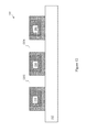
- FIGS. 3-17 illustrate intermediate steps of fabricating the semiconductor device shown in FIG. 1 in accordance with various embodiments of the present disclosure
- FIG. 18 illustrates a flow chart of a method for forming the semiconductor device shown in FIG. 1 in accordance with various embodiments of the present disclosure
- FIGS. 19-22 illustrate intermediate steps of fabricating the semiconductor device shown in FIG. 2 in accordance with various embodiments of the present disclosure.
- FIG. 23 illustrates a flow chart of a method for forming the semiconductor device 200 shown in FIG. 2 in accordance with various embodiments of the present disclosure.
- FIG. 1 illustrates a cross sectional view of a semiconductor device in accordance with various embodiments of the present disclosure.
- the semiconductor device 100 includes a transistor device 150 , which is formed in a substrate 102 and a plurality of interconnect structures formed over the substrate 102 .
- the substrate 102 may be formed of silicon, although it may also be formed of other group III, group IV, and/or group V elements, such as silicon, germanium, gallium, arsenic, and combinations thereof.
- the substrate 102 may also be in the form of silicon-on-insulator (SOI).
- SOI substrate may comprise a layer of a semiconductor material (e.g., silicon, germanium and/or the like) formed over an insulator layer (e.g., buried oxide or the like), which is formed in a silicon substrate.
- insulator layer e.g., buried oxide or the like
- other substrates that may be used include multi-layered substrates, gradient substrates, hybrid orientation substrates and/or the like.
- the substrate 102 may further comprise a variety of electrical circuits such as metal oxide semiconductor (MOS) transistors (e.g., transistor device 150 ) and the associated contact plugs (e.g., contact plug 118 ).
- MOS metal oxide semiconductor
- the electrical circuits formed on the substrate 102 may be any type of circuitry suitable for a particular application.
- the electrical circuits may include various n-type metal-oxide semiconductor (NMOS) and/or p-type metal-oxide semiconductor (PMOS) devices such as transistors, capacitors, resistors, diodes, photo-diodes, fuses and/or the like.
- the electrical circuits may be interconnected to perform one or more functions.
- the transistor device 150 includes a first drain/source region 106 and a second drain/source region 108 .
- the first drain/source region 106 and the second drain/source region 108 are formed on opposite sides of a gate structure of the transistor device 150 .
- the gate structure is formed in a dielectric layer 112 and over the substrate 102 .
- the gate structure may comprise a gate dielectric layer 113 , a gate electrode 114 over the gate dielectric layer 113 and spacers 116 .
- the gate dielectric layer 113 may be a dielectric material such as silicon oxide, silicon oxynitride, silicon nitride, an oxide, a nitrogen-containing oxide, a combination thereof and/or the like.
- the gate dielectric layer 113 may have a relative permittivity value greater than about 4.
- Other examples of such materials include aluminum oxide, lanthanum oxide, hafnium oxide, zirconium oxide, hafnium oxynitride, any combinations thereof and/or the like.
- the gate dielectric layer 113 may be formed by suitable deposition processes such as a plasma enhanced chemical vapor deposition (PECVD) process using tetraethoxysilane (TEOS) and oxygen as a precursor.
- PECVD plasma enhanced chemical vapor deposition
- TEOS tetraethoxysilane
- the gate dielectric layer 113 may be of a thickness in a range from about 8 Angstroms to about 200 Angstroms.
- the gate electrode 114 may comprise a conductive material, such as a metal (e.g., tantalum, titanium, molybdenum, tungsten, platinum, aluminum, hafnium, ruthenium), a metal silicide (e.g., titanium silicide, cobalt silicide, nickel silicide, tantalum silicide), a metal nitride (e.g., titanium nitride, tantalum nitride), doped poly-crystalline silicon, other conductive materials, combinations thereof and/or the like.
- a metal e.g., tantalum, titanium, molybdenum, tungsten, platinum, aluminum, hafnium, ruthenium
- a metal silicide e.g., titanium silicide, cobalt silicide, nickel silicide, tantalum silicide
- a metal nitride e.g., titanium nitride, tantalum nitride
- the spacers 116 may be formed by blanket depositing one or more spacer layers (not shown) over the gate electrode 114 and the substrate 102 .
- the spacers 116 may comprise suitable dielectric materials such as SiN, oxynitride, SiC, SiON, oxide and/or the like.
- the spacers 116 may be formed by commonly used techniques such as chemical vapor deposition (CVD), PECVD, sputtering and/or the like.
- the first and second drain/source regions 106 and 108 may be formed in the substrate 102 on opposing sides of the gate dielectric layer 113 .
- the first and second drain/source regions 106 and 108 may be formed by implanting appropriate p-type dopants such as boron, gallium, indium and/or the like.
- the first and second drain/source regions 106 and 108 may be formed by implanting appropriate n-type dopants such as phosphorous, arsenic and/or the like.
- the isolation regions 104 may be shallow trench isolation (STI) regions.
- the STI regions may be formed by etching the substrate 102 to form a trench and filling the trench with a dielectric material as is known in the art.
- the isolation regions 104 may be filled with a dielectric material such as an oxide material, a high-density plasma (HDP) oxide and/or the like.
- a planarization process such as a chemical mechanical planarization (CMP) process may be applied to the top surface so that the excess dielectric material may be removed as a result.
- CMP chemical mechanical planarization
- each polymer based structure (e.g., structure 222 ) comprises two sidewall portions and a bottom portion.
- the bottom portion of the polymer based structure 222 is formed between the dielectric layer 112 and the corresponding metal line 202 . More particularly, a bottom surface of the bottom portion of the polymer based structure 222 is in direct contact with a top surface of the dielectric layer 112 . A top surface of the bottom portion of the polymer based structure 222 is in direct contact with a bottom surface of the metal line 202 .
- the polymer based structures 224 and 226 are similar to the polymer based structure 222 , and hence are not described in detail herein.
- FIG. 1 further illustrates the first metallization layer 207 comprises two air gaps 203 and 205 .
- a first air gap 203 is between the metal lines 202 and 204 .
- a second air gap 205 is between the metal lines 204 and 206 .
- the formation process of the air gaps 203 and 205 will be described below in detail with respect to FIG. 14 .
- FIG. 1 illustrates two air gaps are formed in the first metallization layer 207
- the semiconductor device 100 could accommodate any number of air gaps.
- Two air gaps e.g., air gaps 203 and 205 ) are illustrated for simplicity.
- FIG. 1 shows one metallization layer (e.g., the second metallization layer 210 ) formed over the first metallization layer 207
- more inter-metal dielectric layers (not shown) and the associated metal lines and vias (not shown) may be formed over the metallization layer 210 .
- the additional layers may be formed by alternating layers of dielectric (e.g., extremely low-k dielectric material) and conductive materials (e.g., copper).
- FIG. 1 further illustrates the semiconductor device 100 comprises an etch stop layer 208 , a first barrier layer 216 and a second barrier layer 218 .
- the etch stop layer 208 is formed over the metal lines 202 , 204 and 206 .
- the etch stop layer 208 may be employed to provide etching selectivity.
- the etch stop layer 208 may function as a barrier layer to prevent diffusion of the metal (e.g., copper) of the metal lines 202 , 204 and 206 into the surrounding dielectric layers (e.g., dielectric layer 201 ).
- the first barrier layer 216 is formed underneath the metal line 212 .
- the first barrier layer 216 wraps the metal line 212 around three sides.
- FIGS. 3-17 illustrate intermediate steps of fabricating the semiconductor device shown in FIG. 1 in accordance with various embodiments of the present disclosure.
- FIG. 3 illustrates a cross sectional view of a dielectric layer in accordance with various embodiments of the present disclosure.
- the dielectric layer 112 may be formed of a low-K dielectric material such as fluorosilicate glass (FSG) and/or the like.
- the dielectric layer 112 may function as an inter-metal dielectric layer.
- the dielectric layer 112 may be formed by suitable deposition techniques such as PECVD techniques, high-density plasma chemical vapor deposition (HDPCVD) and/or the like. It should be noted other features of the semiconductor device 100 shown in FIG. 1 are omitted form FIG. 3 for clarity.
- FIG. 4 illustrates a cross sectional view of the semiconductor device shown in FIG. 3 after a polymer layer is formed over the dielectric layer in accordance with various embodiments.
- the polymer layer 302 is deposited over the dielectric layer 112 through suitable semiconductor fabrication processes such as a spin-coating process and/or the like. Depending on different applications and design needs, the thickness of the polymer layer 302 may vary accordingly. In some embodiments, the thickness of the polymer layer 302 is greater than the thickness of the metal lines 202 , 204 and 206 shown in FIG. 1 .
- the polymer layer 302 is formed of a first polymer material such as polyamic acid having the following schematic chemical formula:
- the polymer layer 302 may be formed of a second polymer material such as epoxy having the following schematic chemical formula:
- FIG. 5 illustrates a cross sectional view of the semiconductor device shown in FIG. 4 after an antireflection layer is formed over the polymer layer in accordance with various embodiments.
- the antireflection layer 304 is employed to reduce reflection during subsequent lithography patterning processes.
- the antireflection layer 304 is a nitrogen-free antireflection layer (NFARC) formed over the polymer layer 302 through suitable deposition processes such as CVD, spin-coating and/or the like.
- NFARC nitrogen-free antireflection layer
- the hard mask layer 306 may be a metal-hard-mask (MHM) layer.
- the hard mask layer 306 may be formed of titanium nitride (TiN).
- the hard mask layer 306 may be formed of other suitable materials such as tantalum nitride (TaN) and/or the like.
- the hard mask layer 306 may be formed by suitable semiconductor fabrication techniques such as CVD and/or the like.
- the hard mask layer 306 may be of a thickness in a range from about 200 Angstroms to about 1400 Angstroms.
- FIG. 6 illustrates a single hard mask layer 306
- a multi-layer hard mask may also be used.
- FIG. 7 illustrates a cross sectional view of the semiconductor device shown in FIG. 6 after a plurality of openings are formed in the polymer layer in accordance with various embodiments.
- openings 702 , 704 and 706 are formed in the polymer layer 302 .
- the openings 702 , 704 and 706 are partially through the polymer layer 302 .
- FIG. 8 illustrates a cross sectional view of the semiconductor device shown in FIG. 7 after a hard mask removal process are applied to the semiconductor device in accordance with various embodiments of the present disclosure.
- the remaining hard mask layer 306 shown in FIG. 7 may be removed using, for example, a wet etch process, a dry etch process or other suitable processes.
- FIG. 9 illustrates a cross sectional view of the semiconductor device shown in FIG. 8 after a conductive material is filled in the openings in accordance with various embodiments of the present disclosure.
- a seed layer (not shown) may be formed in each opening.
- the seed layer may be may be formed of copper, nickel, gold, any combination thereof and/or the like.
- the seed layer may be formed by suitable deposition techniques such as PVD, CVD and/or the like.
- the seed layer may have a thickness in a range from about 50 Angstroms to about 1,000 Angstroms.
- the conductive material such as copper is surrounded by the polymer layer 302 formed of a polymer material (e.g., polyamic acid). It is not necessary to have a barrier layer underneath the conductive material because copper is not able to diffuse into the polymer material.
- a polymer material e.g., polyamic acid
- FIG. 10 illustrates a cross sectional view of the semiconductor device shown in FIG. 9 after a planarization process is performed to remove excess conductive materials in accordance with various embodiments of the present disclosure.
- the planarization process may be implemented by using suitable techniques such as grinding, polishing and/or chemical etching, a combination of etching and grinding techniques.
- the planarization process may be implemented by using a CMP process.
- a CMP process a combination of etching materials and abrading materials are put into contact with the top surface of the semiconductor device and a grinding pad (not shown) is used to grind away excess conductive materials until the top surface of the polymer layer 302 is level with the top surfaces of the metal lines 202 , 204 and 206 .
- FIG. 11A illustrates a cross sectional view of the semiconductor device shown in FIG. 10 after a selective thermal curing process is applied to the polymer layer in accordance with various embodiments of the present disclosure.
- a selective thermal curing process may be employed to cure the polymer material surrounding the metal lines 202 , 204 and 206 .
- the selective thermal curing process may be implemented as an infrared (IR) curing process, an ultraviolet (UV) curing process, a microwave curing process, any combinations thereof and/or the like.
- an infrared (IR) system may be employed to cure the polymer material surrounding the metal lines 202 , 2014 and 206 .
- the IR light is of a wavelength in a range from about 0.7 um to about 15 um.
- the IR light is directed onto the top surfaces of the metal lines 202 , 204 and 206 .
- the metal lines 202 , 204 and 206 may be formed of copper. Since the thermal conductivity of copper is high (e.g., 401 W/(m ⁇ K)), the temperature of the metal lines 202 , 204 and 206 may increase rapidly.
- the polymer layer 302 is of a low thermal conductivity ranging from about 0.1 W/(m ⁇ K) to about 1 W/(m ⁇ K). As a result, the temperature of the polymer layer 302 increases slowly. Such a temperature difference causes heat transfer from the metal lines 202 , 204 and 206 to their surrounding regions as indicated by the arrows.
- the heat transmitted from the metal lines 202 , 204 and 206 may lead to a thermal imidization process.
- the polymer materials surrounding the metal lines 202 , 204 and 206 are converted to polyimide, which is a thermally stable polymer.
- the IR light is applied to the metal lines 202 , 204 and 206 until the polyamic acid portions between the metal lines and the top surface of the dielectric layer 112 have been fully converted into polyimide.
- the heating power of the IR system is in a range from about 10 W to about 1000 W.
- the heating time is in a range from about 30 seconds to about 1 hour. It should be noted that the selection of the heating power and heating time depends on application needs.
- the uncured portion between two adjacent metal lines e.g., metal lines 202 and 204 ) will become an air gap in the subsequent fabrication steps. A longer heating time and/or higher heating power will increase the thickness of the cured portions. As a result, the thickness of the uncured portion may reduce accordingly.
- the width of the air gap shown in FIG. 1 may be adjustable through controlling the heating time and/or the heating power of the curing process. The detailed formation process of the air gaps will be described below with respect to FIGS. 12-14 .
- FIG. 11B illustrates a cross sectional view of the semiconductor device shown in FIG. 11A after thermally stable polymer layers have been formed in accordance with various embodiments of the present disclosure.
- the polymer layer 302 is divided into uncured portion and cured portions 222 , 224 and 226 .
- Each cured portion includes a first sidewall portion, a bottom portion, and a second sidewall portion.
- the bottom portion is between a bottom surface of a corresponding metal line and the top surface of the dielectric layer 112 .
- the sidewall portions and the bottom portion wrap the metal line (e.g., metal line 202 ) on three sides.
- the polymer layer 302 is formed of epoxy.
- the cured portions 222 , 224 and 226 are formed of crosslinking epoxy having the following schematic chemical formula:
- the cured portions shown in FIG. 11B are of high mechanical strength and good thermal stability.
- the material (e.g., polyimide or crosslinking epoxy) of the cured portions shown in FIG. 11B also provides high adhesive strength for the metal lines 202 , 204 and 206 .
- the cured portions 222 , 224 and 226 are of a low dielectric constant.
- the cured portions formed of polyimide are of a dielectric constant in a range from about 2.7 to about 3.5.
- the cured portions formed of crosslinking epoxy are of a dielectric constant in a range from about 3.2 to about 4.6.
- Such a low dielectric constant helps to reduce the capacitive coupling between adjacent metal lines. Such reduced capacitive coupling may help to improve reliability characteristics of the semiconductor device 100 .
- the cured portions shown in FIG. 11 is the polyimide portions or the crosslinking epoxy portions may function as a barrier layer.
- the metal lines 202 , 204 and 206 are formed of copper. The copper of the metal lines 202 , 204 and 206 is not able to diffuse into the cured portions 222 , 224 and 226 . As a result, the fabrication process described herein does not require barrier layers formed underneath the metal lines 202 , 204 and 206 .
- FIG. 12 illustrates a cross sectional view of the semiconductor device shown in FIG. 11B after a cleaning process is applied to the polymer layer in accordance with various embodiments of the present disclosure.
- the uncured polymer layer 302 shown in FIG. 11B may be removed by using suitable solvents.
- the uncured polymer layer 302 formed of polyamic acid may be removed by suitable solvents including dimethylacetamide (DMAc), N-Methyl-2-pyrrolidone (NMP) and/or the like.
- DMAc dimethylacetamide
- NMP N-Methyl-2-pyrrolidone
- the molecular formula of DMAc is C 4 H 9 NO.
- the molar mass of DMAc is 87.12 g mol ⁇ 1 .
- the molecular formula of NMP is C 5 H 9 NO.
- the molar mass of NMP is 99.13 g mol ⁇ 1 .
- the uncured polymer layer 302 formed of epoxy may be removed by suitable solvents including Acetone, Tetrahydrofuran and/or the like.
- suitable solvents including Acetone, Tetrahydrofuran and/or the like.
- the molecular formula of Acetone is C 3 H 6 O.
- the molar mass of Acetone is 53.08 g mol ⁇ 1 .
- the molecular formula of Tetrahydrofuran is C 4 H 8 O.
- the molar mass of Tetrahydrofuran is 72.11 g mol ⁇ 1 .
- the uncured portions shown in FIG. 11B have been removed as shown in FIG. 12 .
- Two trenches 1202 and 1204 have been formed.
- the first trench 1202 is between the metal line 202 and the metal line 204 .
- the second trench 1204 is between the metal line 204 and the metal line 206 .
- the width of the air gaps is adjustable. By controlling the uncured portion's width, the air gap's width may be adjusted accordingly.
- a dry etching process may be employed in order to form trenches.
- the dry etching process may cause metal damages (e.g., barrier damages) that may affect physical and electrical characteristics of the semiconductor device.
- metal damages e.g., barrier damages
- One advantageous feature of having the cleaning process above is that the solvent based cleaning process does not cause metal damages during the formation of trenches 1202 and 1204 .
- FIG. 13 illustrates a cross sectional view of the semiconductor device shown in FIG. 12 after an etch stop layer is formed over the semiconductor device in accordance with various embodiments of the present disclosure.
- the etch stop layer 208 may be formed over the exposed portions of the semiconductor device as shown in FIG. 13 .
- the etch stop layer 208 may be a dielectric material such as such as silicon nitride, silicon oxynitride, silicon oxycarbide, silicon carbide, combinations thereof, and multi-layers thereof.
- the etch stop layer 208 may be formed using a suitable deposition process such as CVD, PECVD, atomic layer deposition (ALD) and/or the like.
- the etch stop layer 208 may be of a thickness in a range from about 300 Angstroms to about 1,500 Angstroms.
- FIG. 14 illustrates a cross sectional view of the semiconductor device shown in FIG. 13 after air gaps are formed in accordance with various embodiments of the present disclosure.
- a dielectric material 1402 may be deposited over the semiconductor device 100 through suitable deposition techniques such as a conformal deposition technique.
- suitable deposition techniques such as a conformal deposition technique.
- two air gaps 203 and 205 may be formed due to the higher aspect ratio (i.e., the ratio between the gap height and gap width) of the openings between two adjacent metal lines.
- the narrow gap width may result in overhangs formed in the upper portions of the gap. Such overhangs may prevent the dielectric material from filling the openings so that air gaps 203 and 205 are formed as shown in FIG. 14 .
- the air gaps 203 and 205 are of a rectangular shape. It should further be noted that the shape shown in FIG. 14 is selected purely for demonstration purposes and are not intended to limit the various embodiments of the present disclosure. For example, it is within the scope and spirit of the present disclosure for the air gaps 203 and 205 to comprise other shapes, such as, but no limited to oval, square, triangle and/or the like.
- One advantageous feature having the air gaps 203 and 205 shown in FIG. 12 is that the air in the air gaps 203 and 205 exhibits a permittivity approximately equal to 1. Such a low permittivity helps to reduce the capacitive coupling between adjacent metal lines (e.g., metal lines 202 and 204 ). Such reduced capacitive coupling may help to improve reliability characteristics.
- FIG. 15 illustrates a cross sectional view of the semiconductor device shown in FIG. 14 after a plurality of opening are formed in accordance with various embodiments of the present disclosure.
- openings 1502 and 1504 are formed in the dielectric layer 1402 .
- the openings 1502 and 1504 may be formed by a dual damascene process, although other suitable techniques such as single damascene may alternatively be used.
- the dual damascene process is well known in the art, and hence is not discussed herein.
- the polyimide layer surrounding the metal line 206 may help to prevent the via hole from punching through to the air gap 205 .
- FIG. 16 illustrates a cross sectional view of the semiconductor device shown in FIG. 15 after two barrier layers are formed in accordance with various embodiments of the present disclosure.
- the barrier layers 216 and 218 may be deposited on the sidewalls as well as the bottoms of their respective openings.
- the barrier layers 216 and 218 may be formed of titanium, titanium nitride, tantalum, tantalum nitride, and combinations thereof and/or the like.
- the barrier layers 216 and 218 may be formed using suitable fabrication techniques such as ALD, PECVD and/or the like.
- FIG. 17 illustrates a cross sectional view of the semiconductor device shown in FIG. 16 after a conductive material is filled in the openings in accordance with various embodiments of the present disclosure.
- a conductive material is then filled in the openings 1602 , and 1604 .
- the conductive material may be copper, but can be any suitable conductive materials, such as copper alloys, aluminum, tungsten, titanium, silver, any combinations thereof and/or the like.
- the conductive material may be formed by suitable fabrication techniques such as an electro-less plating process, CVD, electroplating and/or the like.
- a planarization process is performed to remove excess conductive materials to form the metal lines 212 and 214 .
- the planarization process may be implemented by using suitable techniques such as grinding, polishing and/or chemical etching, a combination of etching and grinding techniques.
- FIG. 18 illustrates a flow chart of a method for forming the semiconductor device shown in FIG. 1 in accordance with various embodiments of the present disclosure.
- This flowchart is merely an example, which should not unduly limit the scope of the claims.
- One of ordinary skill in the art would recognize many variations, alternatives, and modifications. For example, various step as illustrated in FIG. 18 may added, removed, replaced, rearranged and repeated.
- a polymer layer is deposited on a dielectric layer.
- the polymer layer may be formed of suitable materials such as polyamic acid, epoxy and/or the like.
- a hard mask layer is formed over the polymer layer.
- a patterning process is applied to the polymer layer.
- a suitable etching process is employed to form a plurality of openings partially through the polymer layer.
- a conductive material is filled in the openings to form a plurality of metal lines.
- a curing process is applied to the metal lines. As a result, the polymer portions surrounding the metal lines have been cured to form polyimide or crosslinking epoxy regions.
- a cleaning process is employed to remove the uncured portions of the polymer layer.
- an etch stop layer is formed over the metal lines.
- a second dielectric layer is deposited over the metal lines. Air gaps are formed between adjacent metal lines.
- a plurality of openings are formed in the second dielectric layer.
- a conductive material is filled in the openings to form a plurality of metal lines in the second dielectric layer.
- FIGS. 19-22 illustrate intermediate steps of fabricating the semiconductor device shown in FIG. 2 in accordance with various embodiments of the present disclosure.
- the steps for fabricating the semiconductor device 200 shown in FIG. 19 are similar to the steps shown in FIGS. 3-12 , and hence are not discussed in further detail herein to avoid unnecessary repetition.
- FIG. 20 illustrates a cross sectional view of the semiconductor device shown in FIG. 19 after a polymer layer is formed over the semiconductor device in accordance with various embodiments of the present disclosure.
- the polymer layer 213 is formed of polyamic acid, epoxy and/or the like. The formation and structure of polyamic acid and epoxy have been described in detail above with respect to FIG. 4 , and hence are not discussed again to avoid repetition.
- the formation process of air gaps 203 and 205 shown in FIG. 20 is similar to that shown in FIG. 14 , and hence is not discussed again herein.
- a curing process is employed to cure the polymer layer 213 .
- the semiconductor device 200 may be baked in a thermal chamber.
- the curing time is in a range from about 2 minutes to about 4 minutes.
- the curing temperature is in a range from about 250 degrees to about 400 degrees.
- FIG. 21 illustrates a cross sectional view of the semiconductor device shown in FIG. 20 after a plurality of opening are formed in accordance with various embodiments of the present disclosure.
- openings 2102 and 2104 are formed in the polymer layer 213 .
- the openings 2102 and 2104 may be formed by a dual damascene process, although other suitable techniques such as single damascene may alternatively be used.
- FIG. 22 illustrates a cross sectional view of the semiconductor device shown in FIG. 21 after a conductive material is filled in the openings in accordance with various embodiments of the present disclosure.
- a conductive material is filled in the openings 2102 and 2104 .
- the conductive material may be copper, but can be any suitable conductive materials, such as copper alloys, aluminum, tungsten, titanium, silver, any combinations thereof and/or the like.
- the conductive material may be formed by suitable fabrication techniques such as an electro-less plating process, CVD, electroplating and/or the like.
- a planarization process is performed to remove excess conductive materials in accordance with various embodiments of the present disclosure.
- the planarization process may be implemented by using suitable techniques such as grinding, polishing and/or chemical etching, a combination of etching and grinding technique.
- the conductive material such as copper may be filled in the opening directly without having a barrier layer.
- the conductive material such as copper is not able to diffuse into the polymer layer 213 .
- the barrier layer is not formed in the openings.
- Such a barrier free structure shown in FIG. 22 helps to reduce the resistance between the via 217 and the metal line 206 .
- FIG. 23 illustrates a flow chart of a method for forming the semiconductor device 200 shown in FIG. 2 in accordance with various embodiments of the present disclosure.
- This flowchart is merely an example, which should not unduly limit the scope of the claims.
- One of ordinary skill in the art would recognize many variations, alternatives, and modifications. For example, various step as illustrated in FIG. 23 may added, removed, replaced, rearranged and repeated.
- the steps 2302 - 2316 shown in FIG. 23 are similar to the steps 1802 - 1816 shown in FIG. 18 , and hence are not discussed herein to avoid repetition.
- a polymer layer is deposited over the semiconductor device. Air gaps are formed between adjacent metal lines.
- a curing process is applied to the polymer layer. The polymer material is converted into a thermally stable polymer.
- a plurality of openings are formed in the thermally stable polymer layer.
- a conductive material is filled in the openings to form metal lines and vias.
- a method comprises depositing a first polymer layer over a first dielectric layer, wherein at least one gate electrode is embedded in the first dielectric layer, patterning the first polymer layer to form a first trench and a second trench in the first polymer layer, filling the first trench and the second trench with a conductive material to form a first metal line and a second metal line, applying a selective thermal curing process to the first polymer layer until portions of the first polymer layer surrounding the first metal line and the second metal line are cured, removing uncured portions of the first polymer layer through a cleaning process, wherein after the step of removing the uncured portions of the first polymer layer, the first metal line is wrapped by a first cured portion of the first polymer layer on three sides and the second metal line is wrapped by a second cured portion of the first polymer layer on three sides and depositing a second dielectric layer over the first metal line and the second metal line to form an air gap between the first metal line and the second metal line.
- a method comprises depositing a first polymer layer over a first dielectric layer formed on a top surface of a substrate, patterning the first polymer layer to form a first trench and a second trench in the first polymer layer, forming a first metal line and a second metal line in the first trench and the second trench respectively, applying a selective thermal curing process to the first polymer layer until the first metal line is wrapped by a first cured portion of the first polymer layer on three sides and the second metal line is wrapped by a second cured portion of the first polymer layer on three sides, removing uncured portions of the first polymer layer through a cleaning process, depositing a second dielectric layer over the first metal line and the second metal line to form a first metallization layer comprising the first metal line, the second metal line and an air gap between the first metal line and the second metal line and forming a second metallization layer over the first metallization layer, wherein a top surface of the first metal line is in direct contact with a bottom surface of the
- a method comprises depositing a first polymer layer over a first dielectric layer, forming a first opening and a second opening using an etching process, wherein the first opening and the second opening are partially through the first polymer layer, filling the first opening and the second opening with a conductive material to form a first metal line and a second metal line, applying a selective thermal curing process to the first polymer layer until portions of the first polymer layer surrounding the first metal line and the second metal line are cured, removing uncured portions of the first polymer layer through a cleaning process and depositing a second dielectric layer to form an air gap between the first metal line and the second metal line.
Abstract
A method includes depositing a first polymer layer over a first dielectric layer, forming a first opening and a second opening using an etching process, wherein the first opening and the second opening are partially through the first polymer layer, filling the first opening and the second opening with a conductive material to form a first metal line and a second metal line, applying a selective thermal curing process to the first polymer layer until portions of the first polymer layer surrounding the first metal line and the second metal line are cured, removing uncured portions of the first polymer layer through a cleaning process and depositing a second dielectric layer to form an air gap between the first metal line and the second metal line.
Description
This application is a divisional of U.S. patent application Ser. No. 14/334,463, U.S. Pat. No. 9,269,668, entitled “Interconnect Having Air Gaps and Polymer Wrapped Conductive Lines,” filed on Jul. 17, 2014, which application is incorporated herein by reference.
The semiconductor industry has experienced rapid growth due to continuous improvements in the integration density of a variety of electronic components (e.g., transistors, diodes, resistors, capacitors, etc.). For the most part, this improvement in integration density has come from repeated reductions in minimum feature size, which allows more components to be integrated into a given area. As the demand for even smaller electronic devices has grown recently, there has grown a need for smaller and more creative packaging techniques of semiconductor dies.
As semiconductor technologies evolve, wafer-level chip scale package structures have emerged as an effective alternative to further reduce the physical size of semiconductor devices. In a wafer-level chip scale package structure, active devices such as transistors and the like are formed at the top surface of a substrate of the wafer-level chip scale package structure. A variety of metallization layers comprising interconnect structures are formed over the substrate. Interconnection structures of a semiconductor device may comprise a plurality of lateral interconnections such as metal lines and a plurality of vertical interconnections such as vias, plugs and/or the like. The metal lines of the metallization layers are separated by dielectric layers. Trenches and vias are formed in the dielectric layers to provide an electrical connection between metal lines. Various active circuits of a semiconductor device may be coupled to external circuits through a variety of conductive channels formed by the vertical and lateral interconnections.
The metal lines and vias may be formed of copper. In order to prevent interference such as capacitive coupling between two adjacent metal lines from having an impact on the overall performance of the semiconductor device, low-K dielectric materials may be filled between adjacent metal lines. The low-K dielectric materials may be of a dielectric constant approximately equal to and less than 4.0. Furthermore, air gaps may be employed to further reduce capacitive coupling so as to improve the overall performance characteristics of the semiconductor device.
Aspects of the present disclosure are best understood from the following detailed description when read with the accompanying figures. It is noted that, in accordance with the standard practice in the industry, various features are not drawn to scale. In fact, the dimensions of the various features may be arbitrarily increased or reduced for clarity of discussion.
The following disclosure provides many different embodiments, or examples, for implementing different features of the invention. Specific examples of components and arrangements are described below to simplify the present disclosure. These are, of course, merely examples and are not intended to be limiting. For example, the formation of a first feature over or on a second feature in the description that follows may include embodiments in which the first and second features are formed in direct contact, and may also include embodiments in which additional features may be formed between the first and second features, such that the first and second features may not be in direct contact. In addition, the present disclosure may repeat reference numerals and/or letters in the various examples. This repetition is for the purpose of simplicity and clarity and does not in itself dictate a relationship between the various embodiments and/or configurations discussed.
The substrate 102 may be formed of silicon, although it may also be formed of other group III, group IV, and/or group V elements, such as silicon, germanium, gallium, arsenic, and combinations thereof. The substrate 102 may also be in the form of silicon-on-insulator (SOI). The SOI substrate may comprise a layer of a semiconductor material (e.g., silicon, germanium and/or the like) formed over an insulator layer (e.g., buried oxide or the like), which is formed in a silicon substrate. In addition, other substrates that may be used include multi-layered substrates, gradient substrates, hybrid orientation substrates and/or the like.
The substrate 102 may further comprise a variety of electrical circuits such as metal oxide semiconductor (MOS) transistors (e.g., transistor device 150) and the associated contact plugs (e.g., contact plug 118). The electrical circuits formed on the substrate 102 may be any type of circuitry suitable for a particular application. In accordance with an embodiment, the electrical circuits may include various n-type metal-oxide semiconductor (NMOS) and/or p-type metal-oxide semiconductor (PMOS) devices such as transistors, capacitors, resistors, diodes, photo-diodes, fuses and/or the like. The electrical circuits may be interconnected to perform one or more functions. The functions may include memory structures, processing structures, sensors, amplifiers, power distribution, input/output circuitry and/or the like. One of ordinary skill in the art will appreciate that the above examples are provided for illustrative purposes only and are not intended to limit the various embodiments to any particular applications.
As shown in FIG. 1 , the transistor device 150 includes a first drain/source region 106 and a second drain/source region 108. The first drain/source region 106 and the second drain/source region 108 are formed on opposite sides of a gate structure of the transistor device 150. The gate structure is formed in a dielectric layer 112 and over the substrate 102. The gate structure may comprise a gate dielectric layer 113, a gate electrode 114 over the gate dielectric layer 113 and spacers 116.
The gate dielectric layer 113 may be a dielectric material such as silicon oxide, silicon oxynitride, silicon nitride, an oxide, a nitrogen-containing oxide, a combination thereof and/or the like. The gate dielectric layer 113 may have a relative permittivity value greater than about 4. Other examples of such materials include aluminum oxide, lanthanum oxide, hafnium oxide, zirconium oxide, hafnium oxynitride, any combinations thereof and/or the like. In an embodiment in which the gate dielectric layer 113 comprises an oxide layer, the gate dielectric layer 113 may be formed by suitable deposition processes such as a plasma enhanced chemical vapor deposition (PECVD) process using tetraethoxysilane (TEOS) and oxygen as a precursor. In accordance with an embodiment, the gate dielectric layer 113 may be of a thickness in a range from about 8 Angstroms to about 200 Angstroms.
The gate electrode 114 may comprise a conductive material, such as a metal (e.g., tantalum, titanium, molybdenum, tungsten, platinum, aluminum, hafnium, ruthenium), a metal silicide (e.g., titanium silicide, cobalt silicide, nickel silicide, tantalum silicide), a metal nitride (e.g., titanium nitride, tantalum nitride), doped poly-crystalline silicon, other conductive materials, combinations thereof and/or the like. In an embodiment in which the gate electrode 114 is formed of poly-silicon, the gate electrode 114 may be formed by depositing doped or undoped poly-silicon by low-pressure chemical vapor deposition (LPCVD) to a thickness in the range of about 400 Angstroms to about 2,400 Angstroms.
The spacers 116 may be formed by blanket depositing one or more spacer layers (not shown) over the gate electrode 114 and the substrate 102. The spacers 116 may comprise suitable dielectric materials such as SiN, oxynitride, SiC, SiON, oxide and/or the like. The spacers 116 may be formed by commonly used techniques such as chemical vapor deposition (CVD), PECVD, sputtering and/or the like.
The first and second drain/ source regions 106 and 108 may be formed in the substrate 102 on opposing sides of the gate dielectric layer 113. In an embodiment in which the substrate 102 is an n-type substrate, the first and second drain/ source regions 106 and 108 may be formed by implanting appropriate p-type dopants such as boron, gallium, indium and/or the like. Alternatively, in an embodiment in which the substrate 102 is a p-type substrate, the first and second drain/ source regions 106 and 108 may be formed by implanting appropriate n-type dopants such as phosphorous, arsenic and/or the like.
As shown in FIG. 1 , there may be two isolation regions formed on opposite sides of the transistor device 150. The isolation regions 104 may be shallow trench isolation (STI) regions. The STI regions may be formed by etching the substrate 102 to form a trench and filling the trench with a dielectric material as is known in the art. For example, the isolation regions 104 may be filled with a dielectric material such as an oxide material, a high-density plasma (HDP) oxide and/or the like. A planarization process such as a chemical mechanical planarization (CMP) process may be applied to the top surface so that the excess dielectric material may be removed as a result.
The dielectric layer 112 is formed on top of the substrate 102. The dielectric layer 112 may be formed, for example, of a low-K dielectric material, such as silicon oxide. The dielectric layer 112 may be formed by any suitable method known in the art, such as spinning, CVD and PECVD. It should also be noted that one skilled in the art will recognize while FIG. 1 illustrates a single dielectric layer, the dielectric layer 112 may comprise a plurality of dielectric layers.
A first dielectric layer 201 is formed over the dielectric layer 112. In some embodiments, the first dielectric layer 201 is part of a first metallization layer 207. As shown in FIG. 1 , there may be three metal lines 202, 204 and 206 formed in the first metallization layer 207. Each metal line (e.g., metal line 202) is surrounded by a polymer based structure (e.g., structure 222). In some embodiments, the polymer based structures 222, 224 and 226 are formed of polyimide. In alternative embodiments, the polymer based structures 222, 224 and 226 are formed of crosslinking epoxy.
As shown in FIG. 1 , there may be three polymer based structures 222, 224 and 226. Each polymer based structure (e.g., structure 222) comprises two sidewall portions and a bottom portion. For example, as shown in FIG. 1 , the bottom portion of the polymer based structure 222 is formed between the dielectric layer 112 and the corresponding metal line 202. More particularly, a bottom surface of the bottom portion of the polymer based structure 222 is in direct contact with a top surface of the dielectric layer 112. A top surface of the bottom portion of the polymer based structure 222 is in direct contact with a bottom surface of the metal line 202. The polymer based structures 224 and 226 are similar to the polymer based structure 222, and hence are not described in detail herein.
In some embodiments, the metal lines 202, 204 and 206 may be formed of suitable metal materials such as copper, copper alloys, aluminum, silver, tungsten, gold, any combinations thereof and/or the like.
It should be noted that while FIG. 1 illustrates two air gaps are formed in the first metallization layer 207, the semiconductor device 100 could accommodate any number of air gaps. Two air gaps (e.g., air gaps 203 and 205) are illustrated for simplicity.
A second dielectric layer 211 is formed over the first dielectric layer 201. The second dielectric layer 211 is part of a second metallization layer 210. As shown in FIG. 1 , there may be two metal lines 212 and 214 formed in the second metallization layer 210. In addition, there may be a via 217 formed in the second metallization layer 210. As shown in FIG. 1 , the via 217 is coupled between the metal line 214 and the metal line 206. In some embodiments, the via 217 and the metal line 214 may be formed through suitable semiconductor fabrication processes such as a dual damascene process.
While FIG. 1 shows one metallization layer (e.g., the second metallization layer 210) formed over the first metallization layer 207, one skilled in the art will recognize that more inter-metal dielectric layers (not shown) and the associated metal lines and vias (not shown) may be formed over the metallization layer 210. In particular, the additional layers may be formed by alternating layers of dielectric (e.g., extremely low-k dielectric material) and conductive materials (e.g., copper).
In some embodiments, the polymer layer 302 is formed of a first polymer material such as polyamic acid having the following schematic chemical formula:

In alternative embodiments, the polymer layer 302 may be formed of a second polymer material such as epoxy having the following schematic chemical formula:

In some embodiments, the hard mask layer 306 may be a metal-hard-mask (MHM) layer. The hard mask layer 306 may be formed of titanium nitride (TiN). Alternatively, the hard mask layer 306 may be formed of other suitable materials such as tantalum nitride (TaN) and/or the like.
The hard mask layer 306 may be formed by suitable semiconductor fabrication techniques such as CVD and/or the like. The hard mask layer 306 may be of a thickness in a range from about 200 Angstroms to about 1400 Angstroms.
It should be noted while FIG. 6 illustrates a single hard mask layer 306, one of ordinary skill in the art would recognize many variations, alternatives, and modifications. For example, a multi-layer hard mask may also be used.
The openings 702, 704 and 706 may be formed by any suitable semiconductor patterning techniques such as an etching process, a laser ablation process and/or the like. For example, the openings 702, 704 and 706 may be formed by using photolithography techniques to deposit and pattern a photoresist material (not shown) over the semiconductor device 100. A portion of the photoresist is exposed according to the location and shape of the metal lines 202, 204 and 206 shown in FIG. 1 . An etching process, such as an anisotropic dry etch process, may be used to form the openings 702, 704 and 706 extending partially through the polymer layer 302. The remaining portion of the polymer layer under the openings (e.g., opening 702) is of a thickness in a range from about 1 nm to about 5 nm.
In addition, the seed layer may be alloyed with a material that improves the adhesive properties of the seed layer so that it can act as an adhesion layer. For example, the seed layer may be alloyed with a material such as manganese or aluminum, which will migrate to the interface between the seed layer and the barrier layer and will enhance the adhesion between these two layers. The alloying material may be introduced during formation of the seed layer. The alloying material may comprise no more than about 10% of the seed layer. It should be noted that other layers such as barrier layers, glue layers and/or the like may also be used depending on different applications and design needs.
Once the seed layer is formed, a conductive material 902 is then filled in the openings 702, 704 and 706. The conductive material may be copper, but can be any suitable conductive materials, such as copper alloys, aluminum, tungsten, titanium, silver, any combinations thereof and/or the like. The conductive material may be formed by suitable fabrication techniques such as an electro-less plating process, CVD, electroplating and/or the like.
It should be noted the conductive material such as copper is surrounded by the polymer layer 302 formed of a polymer material (e.g., polyamic acid). It is not necessary to have a barrier layer underneath the conductive material because copper is not able to diffuse into the polymer material.
In accordance with various embodiments, the planarization process may be implemented by using a CMP process. In the CMP process, a combination of etching materials and abrading materials are put into contact with the top surface of the semiconductor device and a grinding pad (not shown) is used to grind away excess conductive materials until the top surface of the polymer layer 302 is level with the top surfaces of the metal lines 202, 204 and 206.
In some embodiments, an infrared (IR) system may be employed to cure the polymer material surrounding the metal lines 202, 2014 and 206. The IR light is of a wavelength in a range from about 0.7 um to about 15 um. The IR light is directed onto the top surfaces of the metal lines 202, 204 and 206. In some embodiments, the metal lines 202, 204 and 206 may be formed of copper. Since the thermal conductivity of copper is high (e.g., 401 W/(m·K)), the temperature of the metal lines 202, 204 and 206 may increase rapidly. On the other hand, the polymer layer 302 is of a low thermal conductivity ranging from about 0.1 W/(m·K) to about 1 W/(m·K). As a result, the temperature of the polymer layer 302 increases slowly. Such a temperature difference causes heat transfer from the metal lines 202, 204 and 206 to their surrounding regions as indicated by the arrows.
The heat transmitted from the metal lines 202, 204 and 206 may lead to a thermal imidization process. During the thermal imidization process, the polymer materials surrounding the metal lines 202, 204 and 206 are converted to polyimide, which is a thermally stable polymer. The IR light is applied to the metal lines 202, 204 and 206 until the polyamic acid portions between the metal lines and the top surface of the dielectric layer 112 have been fully converted into polyimide.
In some embodiments, the heating power of the IR system is in a range from about 10 W to about 1000 W. The heating time is in a range from about 30 seconds to about 1 hour. It should be noted that the selection of the heating power and heating time depends on application needs. The uncured portion between two adjacent metal lines (e.g., metal lines 202 and 204) will become an air gap in the subsequent fabrication steps. A longer heating time and/or higher heating power will increase the thickness of the cured portions. As a result, the thickness of the uncured portion may reduce accordingly. As such, the width of the air gap shown in FIG. 1 may be adjustable through controlling the heating time and/or the heating power of the curing process. The detailed formation process of the air gaps will be described below with respect to FIGS. 12-14 .
In some embodiments, the polymer layer 302 is formed of polyamic acid. The cured portions 222, 224 and 226 are formed of polyimide having the following schematic chemical formula:

In some embodiments, the polymer layer 302 is formed of epoxy. The cured portions 222, 224 and 226 are formed of crosslinking epoxy having the following schematic chemical formula:

One advantageous feature of having the cured portions (polyimide or crosslinking epoxy portions) surrounding their respective metal lines is the cured portions shown in FIG. 11B are of high mechanical strength and good thermal stability. In addition, the material (e.g., polyimide or crosslinking epoxy) of the cured portions shown in FIG. 11B also provides high adhesive strength for the metal lines 202, 204 and 206.
Furthermore, the cured portions 222, 224 and 226 are of a low dielectric constant. The cured portions formed of polyimide are of a dielectric constant in a range from about 2.7 to about 3.5. The cured portions formed of crosslinking epoxy are of a dielectric constant in a range from about 3.2 to about 4.6. Such a low dielectric constant helps to reduce the capacitive coupling between adjacent metal lines. Such reduced capacitive coupling may help to improve reliability characteristics of the semiconductor device 100.
Another advantageous feature of having the cured portions surrounding their respective metal lines is the cured portions shown in FIG. 11 is the polyimide portions or the crosslinking epoxy portions may function as a barrier layer. More particularly, in some embodiments, the metal lines 202, 204 and 206 are formed of copper. The copper of the metal lines 202, 204 and 206 is not able to diffuse into the cured portions 222, 224 and 226. As a result, the fabrication process described herein does not require barrier layers formed underneath the metal lines 202, 204 and 206.
In some embodiments, the uncured polymer layer 302 formed of polyamic acid may be removed by suitable solvents including dimethylacetamide (DMAc), N-Methyl-2-pyrrolidone (NMP) and/or the like. The molecular formula of DMAc is C4H9NO. The molar mass of DMAc is 87.12 g mol−1. The molecular formula of NMP is C5H9NO. The molar mass of NMP is 99.13 g mol−1.
In some embodiments, the uncured polymer layer 302 formed of epoxy may be removed by suitable solvents including Acetone, Tetrahydrofuran and/or the like. The molecular formula of Acetone is C3H6O. The molar mass of Acetone is 53.08 g mol−1. The molecular formula of Tetrahydrofuran is C4H8O. The molar mass of Tetrahydrofuran is 72.11 g mol−1.
After the cleaning process finishes, the uncured portions shown in FIG. 11B have been removed as shown in FIG. 12 . Two trenches 1202 and 1204 have been formed. The first trench 1202 is between the metal line 202 and the metal line 204. The second trench 1204 is between the metal line 204 and the metal line 206. It should be noted the width of the air gaps is adjustable. By controlling the uncured portion's width, the air gap's width may be adjusted accordingly.
In a conventional etching based trench formation process, in order to form trenches, a dry etching process may be employed. The dry etching process, however, may cause metal damages (e.g., barrier damages) that may affect physical and electrical characteristics of the semiconductor device. One advantageous feature of having the cleaning process above is that the solvent based cleaning process does not cause metal damages during the formation of trenches 1202 and 1204.
As shown in FIG. 14 , the air gaps 203 and 205 are of a rectangular shape. It should further be noted that the shape shown in FIG. 14 is selected purely for demonstration purposes and are not intended to limit the various embodiments of the present disclosure. For example, it is within the scope and spirit of the present disclosure for the air gaps 203 and 205 to comprise other shapes, such as, but no limited to oval, square, triangle and/or the like.
One advantageous feature having the air gaps 203 and 205 shown in FIG. 12 is that the air in the air gaps 203 and 205 exhibits a permittivity approximately equal to 1. Such a low permittivity helps to reduce the capacitive coupling between adjacent metal lines (e.g., metal lines 202 and 204). Such reduced capacitive coupling may help to improve reliability characteristics.
It should be noted that fabrication defects such as via punch-through issues do not exist in the process of forming the via 217. More particularly, the polyimide layer surrounding the metal line 206 may help to prevent the via hole from punching through to the air gap 205.
A planarization process is performed to remove excess conductive materials to form the metal lines 212 and 214. The planarization process may be implemented by using suitable techniques such as grinding, polishing and/or chemical etching, a combination of etching and grinding techniques.
At step 1802, a polymer layer is deposited on a dielectric layer. The polymer layer may be formed of suitable materials such as polyamic acid, epoxy and/or the like. At step 1804, a hard mask layer is formed over the polymer layer. At step 1806, a patterning process is applied to the polymer layer. At step 1808, a suitable etching process is employed to form a plurality of openings partially through the polymer layer. At step 1812, a conductive material is filled in the openings to form a plurality of metal lines. At step 1814, a curing process is applied to the metal lines. As a result, the polymer portions surrounding the metal lines have been cured to form polyimide or crosslinking epoxy regions.
At step 1816, a cleaning process is employed to remove the uncured portions of the polymer layer. At step 1818, an etch stop layer is formed over the metal lines. At step 1822, a second dielectric layer is deposited over the metal lines. Air gaps are formed between adjacent metal lines. At step 1824, a plurality of openings are formed in the second dielectric layer. At step 1826, a conductive material is filled in the openings to form a plurality of metal lines in the second dielectric layer.
After the polymer layer has been deposited, a curing process is employed to cure the polymer layer 213. During the curing process, the semiconductor device 200 may be baked in a thermal chamber. The curing time is in a range from about 2 minutes to about 4 minutes. The curing temperature is in a range from about 250 degrees to about 400 degrees. After the curing process finishes, the polymer layer 213 formed of polyamic acid is converted into a fully cured polyimide layer.
A planarization process is performed to remove excess conductive materials in accordance with various embodiments of the present disclosure. The planarization process may be implemented by using suitable techniques such as grinding, polishing and/or chemical etching, a combination of etching and grinding technique.
It should be noted that the conductive material such as copper may be filled in the opening directly without having a barrier layer. The conductive material such as copper is not able to diffuse into the polymer layer 213. As a result, the barrier layer is not formed in the openings. Such a barrier free structure shown in FIG. 22 helps to reduce the resistance between the via 217 and the metal line 206.
The steps 2302-2316 shown in FIG. 23 are similar to the steps 1802-1816 shown in FIG. 18 , and hence are not discussed herein to avoid repetition. At step 2318, a polymer layer is deposited over the semiconductor device. Air gaps are formed between adjacent metal lines. At step 2322, a curing process is applied to the polymer layer. The polymer material is converted into a thermally stable polymer. At step 2324, a plurality of openings are formed in the thermally stable polymer layer. At step 2326, a conductive material is filled in the openings to form metal lines and vias.
In accordance with an embodiment, a method comprises depositing a first polymer layer over a first dielectric layer, wherein at least one gate electrode is embedded in the first dielectric layer, patterning the first polymer layer to form a first trench and a second trench in the first polymer layer, filling the first trench and the second trench with a conductive material to form a first metal line and a second metal line, applying a selective thermal curing process to the first polymer layer until portions of the first polymer layer surrounding the first metal line and the second metal line are cured, removing uncured portions of the first polymer layer through a cleaning process, wherein after the step of removing the uncured portions of the first polymer layer, the first metal line is wrapped by a first cured portion of the first polymer layer on three sides and the second metal line is wrapped by a second cured portion of the first polymer layer on three sides and depositing a second dielectric layer over the first metal line and the second metal line to form an air gap between the first metal line and the second metal line.
In accordance with an embodiment, a method comprises depositing a first polymer layer over a first dielectric layer formed on a top surface of a substrate, patterning the first polymer layer to form a first trench and a second trench in the first polymer layer, forming a first metal line and a second metal line in the first trench and the second trench respectively, applying a selective thermal curing process to the first polymer layer until the first metal line is wrapped by a first cured portion of the first polymer layer on three sides and the second metal line is wrapped by a second cured portion of the first polymer layer on three sides, removing uncured portions of the first polymer layer through a cleaning process, depositing a second dielectric layer over the first metal line and the second metal line to form a first metallization layer comprising the first metal line, the second metal line and an air gap between the first metal line and the second metal line and forming a second metallization layer over the first metallization layer, wherein a top surface of the first metal line is in direct contact with a bottom surface of the second metallization layer and a bottom surface of the first metal line and the first dielectric layer are separated by the first cured portion of the first polymer layer.
In accordance with an embodiment, a method comprises depositing a first polymer layer over a first dielectric layer, forming a first opening and a second opening using an etching process, wherein the first opening and the second opening are partially through the first polymer layer, filling the first opening and the second opening with a conductive material to form a first metal line and a second metal line, applying a selective thermal curing process to the first polymer layer until portions of the first polymer layer surrounding the first metal line and the second metal line are cured, removing uncured portions of the first polymer layer through a cleaning process and depositing a second dielectric layer to form an air gap between the first metal line and the second metal line.
The foregoing outlines features of several embodiments so that those skilled in the art may better understand the aspects of the present disclosure. Those skilled in the art should appreciate that they may readily use the present disclosure as a basis for designing or modifying other processes and structures for carrying out the same purposes and/or achieving the same advantages of the embodiments introduced herein. Those skilled in the art should also realize that such equivalent constructions do not depart from the spirit and scope of the present disclosure, and that they may make various changes, substitutions, and alterations herein without departing from the spirit and scope of the present disclosure.
Claims (20)
1. A method comprising:
depositing a first polymer layer over a first dielectric layer, wherein at least one gate electrode is embedded in the first dielectric layer;
patterning the first polymer layer to form a first trench and a second trench in the first polymer layer;
filling the first trench and the second trench with a conductive material to form a first metal line and a second metal line;
applying a selective thermal curing process to the first polymer layer until portions of the first polymer layer surrounding the first metal line and the second metal line are cured;
removing uncured portions of the first polymer layer through a cleaning process, wherein after the step of removing the uncured portions of the first polymer layer, the first metal line is wrapped by a first cured portion of the first polymer layer on three sides and the second metal line is wrapped by a second cured portion of the first polymer layer on three sides; and
depositing a second dielectric layer over the first metal line and the second metal line to form an air gap between the first metal line and the second metal line.
2. The method of claim 1 , wherein:
the first cured portion and the second cured portion of the first polymer layer comprise polyimide.
3. The method of claim 1 , wherein:
the first cured portion and the second cured portion of the first polymer layer comprise crosslinking epoxy.
4. The method of claim 1 , wherein:
the first cured portion of the first polymer layer comprises a first sidewall, a second sidewall and a first bottom, and wherein the first metal line is wrapped by the first sidewall, the second sidewall and the first bottom on three sides, and wherein the first bottom extends from the first metal line to the first dielectric layer; and
the second cured portion of the first polymer layer comprises a third sidewall, a fourth sidewall and a second bottom, and wherein the second metal line is wrapped by the third sidewall, the fourth sidewall and the second bottom on three sides, and wherein the second bottom extends from the second metal line to the first dielectric layer.
5. The method of claim 1 , further comprising:
applying an etching process to the first polymer layer to form the first trench and the second trench, wherein the first trench and the second trench are partially through the first polymer layer.
6. The method of claim 5 , further comprising:
before the step of applying the etching process to the first polymer layer, depositing an antireflection layer on the first polymer layer; and
depositing a mask layer on the antireflection layer.
7. The method of claim 6 , further comprising:
after the step of filling the first trench and the second trench with the conductive material, applying a chemical mechanical polish process to the conductive material and the antireflection layer until the first polymer layer is exposed.
8. The method of claim 1 , further comprising:
forming a first metallization layer comprising the first metal line and second metal line.
9. The method of claim 8 , further comprising:
forming a second metallization layer over the first metallization layer, wherein the air gap is between the second metallization layer and the first dielectric layer, wherein the second metallization layer comprises a plurality of metal lines formed in a second polymer layer.
10. The method of claim 1 , further comprising:
adjusting a width of the air gap by varying heating time and power of an infrared system, wherein the infrared system is directed onto top surfaces of the first metal line and the second metal line.
11. A method comprising:
depositing a first polymer layer over a first dielectric layer formed on a top surface of a substrate;
patterning the first polymer layer to form a first trench and a second trench in the first polymer layer;
forming a first metal line and a second metal line in the first trench and the second trench respectively;
applying a selective thermal curing process to the first polymer layer until the first metal line is wrapped by a first cured portion of the first polymer layer on three sides and the second metal line is wrapped by a second cured portion of the first polymer layer on three sides;
removing uncured portions of the first polymer layer through a cleaning process;
depositing a second dielectric layer over the first metal line and the second metal line to form a first metallization layer comprising the first metal line, the second metal line and an air gap between the first metal line and the second metal line; and
forming a second metallization layer over the first metallization layer, wherein:
a top surface of the first metal line is in direct contact with a bottom surface of the second metallization layer; and
a bottom surface of the first metal line and the first dielectric layer are separated by the first cured portion of the first polymer layer.
12. The method of claim 11 , wherein:
the second metallization layer comprises a second polymer layer and a plurality of interconnect structures.
13. The method of claim 11 , wherein:
the air gap extends from a first cured portion of the first polymer layer to a second cured portion of the first polymer layer.
14. The method of claim 11 , further comprising:
forming an etch stop layer on sidewalls and a bottom of the air gap.
15. A method comprising:
depositing a first polymer layer over a first dielectric layer;
forming a first opening and a second opening using an etching process, wherein the first opening and the second opening are partially through the first polymer layer;
filling the first opening and the second opening with a conductive material to form a first metal line and a second metal line;
applying a selective thermal curing process to the first polymer layer until portions of the first polymer layer surrounding the first metal line and the second metal line are cured;
removing uncured portions of the first polymer layer through a cleaning process; and
depositing a second dielectric layer to form an air gap between the first metal line and the second metal line.
16. The method of claim 15 , further comprising:
directing a heat source onto the first metal line and the second metal line; and
curing the first polymer layer until polyamic acid in regions surrounding the first metal line and the second metal line is converted to polyimide.
17. The method of claim 15 , further comprising:
directing a heat source onto the first metal line and the second metal line; and
curing the first polymer layer until epoxy in regions surrounding the first metal line and the second metal line is converted to crosslinking epoxy.
18. The method of claim 15 , further comprising:
depositing a second polymer layer over the first metal line and the second metal line to form the air gap between the first metal line and the second metal line;
applying a curing process to the second polymer layer; and
forming a via in the second polymer layer, wherein a bottom surface of the via is in direct contact with a top surface of a metal line.
19. The method of claim 18 , further comprising:
the curing process is of a temperature in a range from about 250 degrees to about 400 degrees.
20. The method of claim 15 , wherein:
after the step of removing the uncured portions of the first polymer layer, cured portions of the first polymer layer wraps the first metal line and the second metal line on three sides.
Priority Applications (1)
| Application Number | Priority Date | Filing Date | Title |
|---|---|---|---|
| US15/050,223 US9496170B2 (en) | 2014-07-17 | 2016-02-22 | Interconnect having air gaps and polymer wrapped conductive lines |
Applications Claiming Priority (2)
| Application Number | Priority Date | Filing Date | Title |
|---|---|---|---|
| US14/334,463 US9269668B2 (en) | 2014-07-17 | 2014-07-17 | Interconnect having air gaps and polymer wrapped conductive lines |
| US15/050,223 US9496170B2 (en) | 2014-07-17 | 2016-02-22 | Interconnect having air gaps and polymer wrapped conductive lines |
Related Parent Applications (1)
| Application Number | Title | Priority Date | Filing Date |
|---|---|---|---|
| US14/334,463 Division US9269668B2 (en) | 2014-07-17 | 2014-07-17 | Interconnect having air gaps and polymer wrapped conductive lines |
Publications (2)
| Publication Number | Publication Date |
|---|---|
| US20160172232A1 US20160172232A1 (en) | 2016-06-16 |
| US9496170B2 true US9496170B2 (en) | 2016-11-15 |
Family
ID=55075205
Family Applications (2)
| Application Number | Title | Priority Date | Filing Date |
|---|---|---|---|
| US14/334,463 Expired - Fee Related US9269668B2 (en) | 2014-07-17 | 2014-07-17 | Interconnect having air gaps and polymer wrapped conductive lines |
| US15/050,223 Active US9496170B2 (en) | 2014-07-17 | 2016-02-22 | Interconnect having air gaps and polymer wrapped conductive lines |
Family Applications Before (1)
| Application Number | Title | Priority Date | Filing Date |
|---|---|---|---|
| US14/334,463 Expired - Fee Related US9269668B2 (en) | 2014-07-17 | 2014-07-17 | Interconnect having air gaps and polymer wrapped conductive lines |
Country Status (2)
| Country | Link |
|---|---|
| US (2) | US9269668B2 (en) |
| CN (1) | CN105280616B (en) |
Cited By (1)
| Publication number | Priority date | Publication date | Assignee | Title |
|---|---|---|---|---|
| US11696812B2 (en) | 2016-10-24 | 2023-07-11 | Invuity, Inc. | Lighting element |
Families Citing this family (8)
| Publication number | Priority date | Publication date | Assignee | Title |
|---|---|---|---|---|
| US8896125B2 (en) | 2011-07-05 | 2014-11-25 | Sony Corporation | Semiconductor device, fabrication method for a semiconductor device and electronic apparatus |
| US9431343B1 (en) * | 2015-03-11 | 2016-08-30 | Samsung Electronics Co., Ltd. | Stacked damascene structures for microelectronic devices |
| US9449871B1 (en) * | 2015-11-18 | 2016-09-20 | International Business Machines Corporation | Hybrid airgap structure with oxide liner |
| US9666528B1 (en) * | 2016-02-23 | 2017-05-30 | International Business Machines Corporation | BEOL vertical fuse formed over air gap |
| CN106803496B (en) * | 2016-12-29 | 2019-09-13 | 上海集成电路研发中心有限公司 | A method of generating air-gap structure in post-channel interconnection |
| CN109545735B (en) * | 2017-09-22 | 2022-01-28 | 蓝枪半导体有限责任公司 | Metal internal connection structure and its making method |
| CN110148583B (en) * | 2019-05-14 | 2021-06-18 | 上海华虹宏力半导体制造有限公司 | Method for forming metal interconnection structure |
| US11605558B2 (en) * | 2021-03-26 | 2023-03-14 | Taiwan Semiconductor Manufacturing Co., Ltd. | Integrated circuit interconnect structure having discontinuous barrier layer and air gap |
Citations (40)
| Publication number | Priority date | Publication date | Assignee | Title |
|---|---|---|---|---|
| US5668398A (en) | 1994-05-27 | 1997-09-16 | Texas Instruments Incorporated | Multilevel interconnect structure with air gaps formed between metal leads |
| US6165897A (en) | 1998-05-29 | 2000-12-26 | Taiwan Semiconductor Manufacturing Company | Void forming method for fabricating low dielectric constant dielectric layer |
| US6265321B1 (en) | 2000-04-17 | 2001-07-24 | Chartered Semiconductor Manufacturing Ltd. | Air bridge process for forming air gaps |
| US6303464B1 (en) | 1996-12-30 | 2001-10-16 | Intel Corporation | Method and structure for reducing interconnect system capacitance through enclosed voids in a dielectric layer |
| US6445072B1 (en) | 2000-07-17 | 2002-09-03 | Advanced Micro Devices, Inc. | Deliberate void in innerlayer dielectric gapfill to reduce dielectric constant |
| US6838355B1 (en) * | 2003-08-04 | 2005-01-04 | International Business Machines Corporation | Damascene interconnect structures including etchback for low-k dielectric materials |
| US6841844B2 (en) | 2001-09-28 | 2005-01-11 | Sharp Laboratories Of America, Inc. | Air gaps copper interconnect structure |
| US20050037604A1 (en) | 2000-02-08 | 2005-02-17 | International Business Machines Corporation | Multilayer interconnect structure containing air gaps and method for making |
| US6905938B2 (en) * | 2001-04-24 | 2005-06-14 | United Microelectronics Corp. | Method of forming interconnect structure with low dielectric constant |
| US7037744B2 (en) | 2004-03-19 | 2006-05-02 | International Business Machines Corporation | Method for fabricating a self-aligned nanocolumnar airbridge and structure produced thereby |
| US7094669B2 (en) | 2004-08-03 | 2006-08-22 | Chartered Semiconductor Manufacturing Ltd | Structure and method of liner air gap formation |
| US7132306B1 (en) | 2003-12-08 | 2006-11-07 | Advanced Micro Devices, Inc. | Method of forming an interlevel dielectric layer employing dielectric etch-back process without extra mask set |
| US7138329B2 (en) * | 2002-11-15 | 2006-11-21 | United Microelectronics Corporation | Air gap for tungsten/aluminum plug applications |
| US7285474B2 (en) | 2004-09-16 | 2007-10-23 | International Business Machines Corporation | Air-gap insulated interconnections |
| US20080171136A1 (en) | 2005-07-27 | 2008-07-17 | Geraud Jean-Michel Dubois | Low-k interlevel dielectric materials and method of forming low-k interlevel dielectric layers and structures |
| US7405149B1 (en) | 1998-12-21 | 2008-07-29 | Megica Corporation | Post passivation method for semiconductor chip or wafer |
| US20080185722A1 (en) | 2007-02-05 | 2008-08-07 | Chung-Shi Liu | Formation process of interconnect structures with air-gaps and sidewall spacers |
| US20090001586A1 (en) | 2000-01-18 | 2009-01-01 | Micron Technology, Inc. | Integrated circuit and seed layers |
| US20090001589A1 (en) | 2007-06-26 | 2009-01-01 | Sung-Joong Joo | Nor flash device and method for fabricating the device |
| US20090087562A1 (en) | 2007-09-27 | 2009-04-02 | Long Hua Lee | Method of preparing cross-linked organic glasses for air-gap sacrificial layers |
| US7553756B2 (en) | 2005-11-16 | 2009-06-30 | Hitachi, Ltd. | Process for producing semiconductor integrated circuit device |
| US20090294898A1 (en) | 2008-05-30 | 2009-12-03 | Frank Feustel | Microstructure device including a metallization structure with self-aligned air gaps between closely spaced metal lines |
| US7662722B2 (en) | 2007-01-24 | 2010-02-16 | International Business Machines Corporation | Air gap under on-chip passive device |
| US7687394B2 (en) * | 2005-12-05 | 2010-03-30 | Dongbu Electronics Co., Ltd. | Method for forming inter-layer dielectric of low dielectric constant and method for forming copper wiring using the same |
| US20100093168A1 (en) | 2008-10-10 | 2010-04-15 | Mehul Naik | Air gap interconnects using carbon-based films |
| US20100090346A1 (en) * | 2006-01-18 | 2010-04-15 | Joaquin Torres | Integration of self-aligned trenches in-between metal lines |
| US7842600B2 (en) | 2008-05-28 | 2010-11-30 | Samsung Electronics Co., Ltd. | Methods of forming interlayer dielectrics having air gaps |
| US7960275B2 (en) | 2007-03-16 | 2011-06-14 | Commissariat A L'energie Atomique | Method for manufacturing an interconnection structure with cavities for an integrated circuit |
| US8003520B2 (en) | 2007-12-03 | 2011-08-23 | International Business Machines Corporation | Air gap structure having protective metal silicide pads on a metal feature |
| US8198701B2 (en) | 2007-01-25 | 2012-06-12 | Samsung Electronics Co., Ltd. | Semiconductor device having thermally formed air gap in wiring layer and method of fabricating same |
| US8241992B2 (en) | 2010-05-10 | 2012-08-14 | International Business Machines Corporation | Method for air gap interconnect integration using photo-patternable low k material |
| US20120276711A1 (en) | 2011-04-27 | 2012-11-01 | Hynix Semiconductor Inc. | Method for manufacturing semiconductor device having spacer with air gap |
| US8344474B2 (en) | 2009-02-27 | 2013-01-01 | Advanced Micro Devices, Inc. | Microstructure device including a metallization structure with self-aligned air gaps and refilled air gap exclusion zones |
| US8461678B2 (en) | 2009-01-20 | 2013-06-11 | International Business Machines Corporation | Structure with self aligned resist layer on an interconnect surface and method of making same |
| US20140264896A1 (en) | 2013-03-12 | 2014-09-18 | Taiwan Semiconductor Manufacturing Company, Ltd. | Structure and Method for a Low-K Dielectric with Pillar-Type Air-Gaps |
| US8860229B1 (en) | 2013-07-16 | 2014-10-14 | Taiwan Semiconductor Manufacturing Co., Ltd. | Hybrid bonding with through substrate via (TSV) |
| US8883610B2 (en) * | 2008-11-28 | 2014-11-11 | Globalfoundries Inc. | Microstructure device including a metallization structure with self-aligned air gaps between closely spaced metal lines |
| US8952539B2 (en) * | 2010-03-10 | 2015-02-10 | International Business Machines Corporation | Methods for fabrication of an air gap-containing interconnect structure |
| US20150145062A1 (en) | 2013-11-25 | 2015-05-28 | International Business Machines Corporation | Variable length multi-channel replacement metal gate including silicon hard mask |
| US9087821B2 (en) | 2013-07-16 | 2015-07-21 | Taiwan Semiconductor Manufacturing Co., Ltd. | Hybrid bonding with through substrate via (TSV) |
Family Cites Families (1)
| Publication number | Priority date | Publication date | Assignee | Title |
|---|---|---|---|---|
| US8659155B2 (en) * | 2009-11-05 | 2014-02-25 | Taiwan Semiconductor Manufacturing Company, Ltd. | Mechanisms for forming copper pillar bumps |
-
2014
- 2014-07-17 US US14/334,463 patent/US9269668B2/en not_active Expired - Fee Related
- 2014-12-22 CN CN201410803165.2A patent/CN105280616B/en active Active
-
2016
- 2016-02-22 US US15/050,223 patent/US9496170B2/en active Active
Patent Citations (40)
| Publication number | Priority date | Publication date | Assignee | Title |
|---|---|---|---|---|
| US5668398A (en) | 1994-05-27 | 1997-09-16 | Texas Instruments Incorporated | Multilevel interconnect structure with air gaps formed between metal leads |
| US6303464B1 (en) | 1996-12-30 | 2001-10-16 | Intel Corporation | Method and structure for reducing interconnect system capacitance through enclosed voids in a dielectric layer |
| US6165897A (en) | 1998-05-29 | 2000-12-26 | Taiwan Semiconductor Manufacturing Company | Void forming method for fabricating low dielectric constant dielectric layer |
| US7405149B1 (en) | 1998-12-21 | 2008-07-29 | Megica Corporation | Post passivation method for semiconductor chip or wafer |
| US20090001586A1 (en) | 2000-01-18 | 2009-01-01 | Micron Technology, Inc. | Integrated circuit and seed layers |
| US20050037604A1 (en) | 2000-02-08 | 2005-02-17 | International Business Machines Corporation | Multilayer interconnect structure containing air gaps and method for making |
| US6265321B1 (en) | 2000-04-17 | 2001-07-24 | Chartered Semiconductor Manufacturing Ltd. | Air bridge process for forming air gaps |
| US6445072B1 (en) | 2000-07-17 | 2002-09-03 | Advanced Micro Devices, Inc. | Deliberate void in innerlayer dielectric gapfill to reduce dielectric constant |
| US6905938B2 (en) * | 2001-04-24 | 2005-06-14 | United Microelectronics Corp. | Method of forming interconnect structure with low dielectric constant |
| US6841844B2 (en) | 2001-09-28 | 2005-01-11 | Sharp Laboratories Of America, Inc. | Air gaps copper interconnect structure |
| US7138329B2 (en) * | 2002-11-15 | 2006-11-21 | United Microelectronics Corporation | Air gap for tungsten/aluminum plug applications |
| US6838355B1 (en) * | 2003-08-04 | 2005-01-04 | International Business Machines Corporation | Damascene interconnect structures including etchback for low-k dielectric materials |
| US7132306B1 (en) | 2003-12-08 | 2006-11-07 | Advanced Micro Devices, Inc. | Method of forming an interlevel dielectric layer employing dielectric etch-back process without extra mask set |
| US7037744B2 (en) | 2004-03-19 | 2006-05-02 | International Business Machines Corporation | Method for fabricating a self-aligned nanocolumnar airbridge and structure produced thereby |
| US7094669B2 (en) | 2004-08-03 | 2006-08-22 | Chartered Semiconductor Manufacturing Ltd | Structure and method of liner air gap formation |
| US7285474B2 (en) | 2004-09-16 | 2007-10-23 | International Business Machines Corporation | Air-gap insulated interconnections |
| US20080171136A1 (en) | 2005-07-27 | 2008-07-17 | Geraud Jean-Michel Dubois | Low-k interlevel dielectric materials and method of forming low-k interlevel dielectric layers and structures |
| US7553756B2 (en) | 2005-11-16 | 2009-06-30 | Hitachi, Ltd. | Process for producing semiconductor integrated circuit device |
| US7687394B2 (en) * | 2005-12-05 | 2010-03-30 | Dongbu Electronics Co., Ltd. | Method for forming inter-layer dielectric of low dielectric constant and method for forming copper wiring using the same |
| US20100090346A1 (en) * | 2006-01-18 | 2010-04-15 | Joaquin Torres | Integration of self-aligned trenches in-between metal lines |
| US7662722B2 (en) | 2007-01-24 | 2010-02-16 | International Business Machines Corporation | Air gap under on-chip passive device |
| US8198701B2 (en) | 2007-01-25 | 2012-06-12 | Samsung Electronics Co., Ltd. | Semiconductor device having thermally formed air gap in wiring layer and method of fabricating same |
| US20080185722A1 (en) | 2007-02-05 | 2008-08-07 | Chung-Shi Liu | Formation process of interconnect structures with air-gaps and sidewall spacers |
| US7960275B2 (en) | 2007-03-16 | 2011-06-14 | Commissariat A L'energie Atomique | Method for manufacturing an interconnection structure with cavities for an integrated circuit |
| US20090001589A1 (en) | 2007-06-26 | 2009-01-01 | Sung-Joong Joo | Nor flash device and method for fabricating the device |
| US20090087562A1 (en) | 2007-09-27 | 2009-04-02 | Long Hua Lee | Method of preparing cross-linked organic glasses for air-gap sacrificial layers |
| US8003520B2 (en) | 2007-12-03 | 2011-08-23 | International Business Machines Corporation | Air gap structure having protective metal silicide pads on a metal feature |
| US7842600B2 (en) | 2008-05-28 | 2010-11-30 | Samsung Electronics Co., Ltd. | Methods of forming interlayer dielectrics having air gaps |
| US20090294898A1 (en) | 2008-05-30 | 2009-12-03 | Frank Feustel | Microstructure device including a metallization structure with self-aligned air gaps between closely spaced metal lines |
| US20100093168A1 (en) | 2008-10-10 | 2010-04-15 | Mehul Naik | Air gap interconnects using carbon-based films |
| US8883610B2 (en) * | 2008-11-28 | 2014-11-11 | Globalfoundries Inc. | Microstructure device including a metallization structure with self-aligned air gaps between closely spaced metal lines |
| US8461678B2 (en) | 2009-01-20 | 2013-06-11 | International Business Machines Corporation | Structure with self aligned resist layer on an interconnect surface and method of making same |
| US8344474B2 (en) | 2009-02-27 | 2013-01-01 | Advanced Micro Devices, Inc. | Microstructure device including a metallization structure with self-aligned air gaps and refilled air gap exclusion zones |
| US8952539B2 (en) * | 2010-03-10 | 2015-02-10 | International Business Machines Corporation | Methods for fabrication of an air gap-containing interconnect structure |
| US8241992B2 (en) | 2010-05-10 | 2012-08-14 | International Business Machines Corporation | Method for air gap interconnect integration using photo-patternable low k material |
| US20120276711A1 (en) | 2011-04-27 | 2012-11-01 | Hynix Semiconductor Inc. | Method for manufacturing semiconductor device having spacer with air gap |
| US20140264896A1 (en) | 2013-03-12 | 2014-09-18 | Taiwan Semiconductor Manufacturing Company, Ltd. | Structure and Method for a Low-K Dielectric with Pillar-Type Air-Gaps |
| US8860229B1 (en) | 2013-07-16 | 2014-10-14 | Taiwan Semiconductor Manufacturing Co., Ltd. | Hybrid bonding with through substrate via (TSV) |
| US9087821B2 (en) | 2013-07-16 | 2015-07-21 | Taiwan Semiconductor Manufacturing Co., Ltd. | Hybrid bonding with through substrate via (TSV) |
| US20150145062A1 (en) | 2013-11-25 | 2015-05-28 | International Business Machines Corporation | Variable length multi-channel replacement metal gate including silicon hard mask |
Cited By (1)
| Publication number | Priority date | Publication date | Assignee | Title |
|---|---|---|---|---|
| US11696812B2 (en) | 2016-10-24 | 2023-07-11 | Invuity, Inc. | Lighting element |
Also Published As
| Publication number | Publication date |
|---|---|
| US9269668B2 (en) | 2016-02-23 |
| CN105280616B (en) | 2019-02-05 |
| CN105280616A (en) | 2016-01-27 |
| US20160172232A1 (en) | 2016-06-16 |
| US20160020176A1 (en) | 2016-01-21 |
Similar Documents
| Publication | Publication Date | Title |
|---|---|---|
| US9496170B2 (en) | Interconnect having air gaps and polymer wrapped conductive lines | |
| US11728296B2 (en) | Interconnect structure and method of forming same | |
| US9953920B2 (en) | Interconnect structure and method | |
| TW541657B (en) | Semiconductor device and its fabrication method | |
| US11101216B2 (en) | Metal line structure and method | |
| US9478466B2 (en) | Metal gate structure and method | |
| WO2013106796A1 (en) | Integrating through substrate vias into middle-of-line layers of integrated circuits | |
| US9520371B2 (en) | Planar passivation for pads | |
| US8728936B1 (en) | Copper etching integration scheme | |
| US11011419B2 (en) | Method for forming interconnect structure | |
| US9847296B2 (en) | Barrier layer and structure method | |
| US9564507B2 (en) | Interlayer dielectric layer with two tensile dielectric layers |
Legal Events
| Date | Code | Title | Description |
|---|---|---|---|
| STCF | Information on status: patent grant |
Free format text: PATENTED CASE |
|
| MAFP | Maintenance fee payment |
Free format text: PAYMENT OF MAINTENANCE FEE, 4TH YEAR, LARGE ENTITY (ORIGINAL EVENT CODE: M1551); ENTITY STATUS OF PATENT OWNER: LARGE ENTITY Year of fee payment: 4 |