US9492296B2 - Stent devices made of a lattice with smooth shape cells improving stent fatigue life - Google Patents
Stent devices made of a lattice with smooth shape cells improving stent fatigue life Download PDFInfo
- Publication number
- US9492296B2 US9492296B2 US13/659,398 US201213659398A US9492296B2 US 9492296 B2 US9492296 B2 US 9492296B2 US 201213659398 A US201213659398 A US 201213659398A US 9492296 B2 US9492296 B2 US 9492296B2
- Authority
- US
- United States
- Prior art keywords
- stent
- lattice
- curvature
- unit cell
- curve
- Prior art date
- Legal status (The legal status is an assumption and is not a legal conclusion. Google has not performed a legal analysis and makes no representation as to the accuracy of the status listed.)
- Expired - Fee Related, expires
Links
Images


Classifications
-
- A—HUMAN NECESSITIES
- A61—MEDICAL OR VETERINARY SCIENCE; HYGIENE
- A61F—FILTERS IMPLANTABLE INTO BLOOD VESSELS; PROSTHESES; DEVICES PROVIDING PATENCY TO, OR PREVENTING COLLAPSING OF, TUBULAR STRUCTURES OF THE BODY, e.g. STENTS; ORTHOPAEDIC, NURSING OR CONTRACEPTIVE DEVICES; FOMENTATION; TREATMENT OR PROTECTION OF EYES OR EARS; BANDAGES, DRESSINGS OR ABSORBENT PADS; FIRST-AID KITS
- A61F2/00—Filters implantable into blood vessels; Prostheses, i.e. artificial substitutes or replacements for parts of the body; Appliances for connecting them with the body; Devices providing patency to, or preventing collapsing of, tubular structures of the body, e.g. stents
- A61F2/82—Devices providing patency to, or preventing collapsing of, tubular structures of the body, e.g. stents
- A61F2/86—Stents in a form characterised by the wire-like elements; Stents in the form characterised by a net-like or mesh-like structure
- A61F2/90—Stents in a form characterised by the wire-like elements; Stents in the form characterised by a net-like or mesh-like structure characterised by a net-like or mesh-like structure
- A61F2/91—Stents in a form characterised by the wire-like elements; Stents in the form characterised by a net-like or mesh-like structure characterised by a net-like or mesh-like structure made from perforated sheet material or tubes, e.g. perforated by laser cuts or etched holes
- A61F2/915—Stents in a form characterised by the wire-like elements; Stents in the form characterised by a net-like or mesh-like structure characterised by a net-like or mesh-like structure made from perforated sheet material or tubes, e.g. perforated by laser cuts or etched holes with bands having a meander structure, adjacent bands being connected to each other
-
- G06F17/50—
-
- G—PHYSICS
- G06—COMPUTING; CALCULATING OR COUNTING
- G06F—ELECTRIC DIGITAL DATA PROCESSING
- G06F30/00—Computer-aided design [CAD]
-
- A—HUMAN NECESSITIES
- A61—MEDICAL OR VETERINARY SCIENCE; HYGIENE
- A61F—FILTERS IMPLANTABLE INTO BLOOD VESSELS; PROSTHESES; DEVICES PROVIDING PATENCY TO, OR PREVENTING COLLAPSING OF, TUBULAR STRUCTURES OF THE BODY, e.g. STENTS; ORTHOPAEDIC, NURSING OR CONTRACEPTIVE DEVICES; FOMENTATION; TREATMENT OR PROTECTION OF EYES OR EARS; BANDAGES, DRESSINGS OR ABSORBENT PADS; FIRST-AID KITS
- A61F2/00—Filters implantable into blood vessels; Prostheses, i.e. artificial substitutes or replacements for parts of the body; Appliances for connecting them with the body; Devices providing patency to, or preventing collapsing of, tubular structures of the body, e.g. stents
- A61F2/02—Prostheses implantable into the body
- A61F2/04—Hollow or tubular parts of organs, e.g. bladders, tracheae, bronchi or bile ducts
- A61F2/06—Blood vessels
- A61F2/07—Stent-grafts
-
- A—HUMAN NECESSITIES
- A61—MEDICAL OR VETERINARY SCIENCE; HYGIENE
- A61F—FILTERS IMPLANTABLE INTO BLOOD VESSELS; PROSTHESES; DEVICES PROVIDING PATENCY TO, OR PREVENTING COLLAPSING OF, TUBULAR STRUCTURES OF THE BODY, e.g. STENTS; ORTHOPAEDIC, NURSING OR CONTRACEPTIVE DEVICES; FOMENTATION; TREATMENT OR PROTECTION OF EYES OR EARS; BANDAGES, DRESSINGS OR ABSORBENT PADS; FIRST-AID KITS
- A61F2/00—Filters implantable into blood vessels; Prostheses, i.e. artificial substitutes or replacements for parts of the body; Appliances for connecting them with the body; Devices providing patency to, or preventing collapsing of, tubular structures of the body, e.g. stents
- A61F2/02—Prostheses implantable into the body
- A61F2/24—Heart valves ; Vascular valves, e.g. venous valves; Heart implants, e.g. passive devices for improving the function of the native valve or the heart muscle; Transmyocardial revascularisation [TMR] devices; Valves implantable in the body
- A61F2/2412—Heart valves ; Vascular valves, e.g. venous valves; Heart implants, e.g. passive devices for improving the function of the native valve or the heart muscle; Transmyocardial revascularisation [TMR] devices; Valves implantable in the body with soft flexible valve members, e.g. tissue valves shaped like natural valves
- A61F2/2418—Scaffolds therefor, e.g. support stents
-
- A—HUMAN NECESSITIES
- A61—MEDICAL OR VETERINARY SCIENCE; HYGIENE
- A61F—FILTERS IMPLANTABLE INTO BLOOD VESSELS; PROSTHESES; DEVICES PROVIDING PATENCY TO, OR PREVENTING COLLAPSING OF, TUBULAR STRUCTURES OF THE BODY, e.g. STENTS; ORTHOPAEDIC, NURSING OR CONTRACEPTIVE DEVICES; FOMENTATION; TREATMENT OR PROTECTION OF EYES OR EARS; BANDAGES, DRESSINGS OR ABSORBENT PADS; FIRST-AID KITS
- A61F2/00—Filters implantable into blood vessels; Prostheses, i.e. artificial substitutes or replacements for parts of the body; Appliances for connecting them with the body; Devices providing patency to, or preventing collapsing of, tubular structures of the body, e.g. stents
- A61F2/82—Devices providing patency to, or preventing collapsing of, tubular structures of the body, e.g. stents
- A61F2/86—Stents in a form characterised by the wire-like elements; Stents in the form characterised by a net-like or mesh-like structure
- A61F2/90—Stents in a form characterised by the wire-like elements; Stents in the form characterised by a net-like or mesh-like structure characterised by a net-like or mesh-like structure
- A61F2/91—Stents in a form characterised by the wire-like elements; Stents in the form characterised by a net-like or mesh-like structure characterised by a net-like or mesh-like structure made from perforated sheet material or tubes, e.g. perforated by laser cuts or etched holes
- A61F2/915—Stents in a form characterised by the wire-like elements; Stents in the form characterised by a net-like or mesh-like structure characterised by a net-like or mesh-like structure made from perforated sheet material or tubes, e.g. perforated by laser cuts or etched holes with bands having a meander structure, adjacent bands being connected to each other
- A61F2002/9155—Adjacent bands being connected to each other
- A61F2002/91575—Adjacent bands being connected to each other connected peak to trough
-
- A—HUMAN NECESSITIES
- A61—MEDICAL OR VETERINARY SCIENCE; HYGIENE
- A61F—FILTERS IMPLANTABLE INTO BLOOD VESSELS; PROSTHESES; DEVICES PROVIDING PATENCY TO, OR PREVENTING COLLAPSING OF, TUBULAR STRUCTURES OF THE BODY, e.g. STENTS; ORTHOPAEDIC, NURSING OR CONTRACEPTIVE DEVICES; FOMENTATION; TREATMENT OR PROTECTION OF EYES OR EARS; BANDAGES, DRESSINGS OR ABSORBENT PADS; FIRST-AID KITS
- A61F2230/00—Geometry of prostheses classified in groups A61F2/00 - A61F2/26 or A61F2/82 or A61F9/00 or A61F11/00 or subgroups thereof
- A61F2230/0002—Two-dimensional shapes, e.g. cross-sections
- A61F2230/0004—Rounded shapes, e.g. with rounded corners
- A61F2230/0013—Horseshoe-shaped, e.g. crescent-shaped, C-shaped, U-shaped
-
- A—HUMAN NECESSITIES
- A61—MEDICAL OR VETERINARY SCIENCE; HYGIENE
- A61F—FILTERS IMPLANTABLE INTO BLOOD VESSELS; PROSTHESES; DEVICES PROVIDING PATENCY TO, OR PREVENTING COLLAPSING OF, TUBULAR STRUCTURES OF THE BODY, e.g. STENTS; ORTHOPAEDIC, NURSING OR CONTRACEPTIVE DEVICES; FOMENTATION; TREATMENT OR PROTECTION OF EYES OR EARS; BANDAGES, DRESSINGS OR ABSORBENT PADS; FIRST-AID KITS
- A61F2230/00—Geometry of prostheses classified in groups A61F2/00 - A61F2/26 or A61F2/82 or A61F9/00 or A61F11/00 or subgroups thereof
- A61F2230/0002—Two-dimensional shapes, e.g. cross-sections
- A61F2230/0028—Shapes in the form of latin or greek characters
- A61F2230/0054—V-shaped
Definitions
- the present invention relates to the field of medical stents, and more particularly to methods and systems for designing medical stents, and the stents produced thereby.
- Intravascular stents are primarily used to open and scaffold tubular passages or lumens such as blood vessels, biliary ducts and the esophagus. They usually consist of expandable lattice meshes that can deploy and hold endovascular grafts, arterial endoprosthesis and self-expanding heart valve implants.
- Peak stresses due to stress concentrations tend to occur in the lattice structures of known prior art stents, which lead to fatigue life issues and other undesirable characteristics. More particularly, lattices formed of closed cells having uneven shapes or curved boundaries having abrupt changes in geometry will tend to cause undesirable stress concentrations. Peak stresses due to stress concentration are also a crucial factor in the delamination of a polymer coating from an arched region of a lattice stent. This phenomenon has the potential to contribute to thrombus formation and can lead to in-stent restenosis and/or change of drug release rate for drug eluted stents.
- a method for generating a lattice cell shape for a stent made of a lattice of a given material comprising: generating a unit cell model representing the lattice cell, the unit cell model comprising a plurality of geometric primitives interconnected by blending points, each of the geometric primitives defining a G2-continuous curve at the blending points; setting a weighting factor to a same value for each one of the plurality of blending points, the weighting factor representing a contribution of a corresponding one of the plurality of blending points to a curvature of an optimal curve; determining a curvature of the G 2 -continuous curve as a function of the weighting factors having the same value; and structurally optimizing the unit cell model by iteratively determining a variable value for the weighting factor value for each one of the plurality of blending points using stress and/or strain characteristics for the given material, determining a new curvature of the G 2 -continu
- a method of forming a stent of a given material with a lattice structure having a plurality of lattice cells comprising: generating a unit cell model representing one of said lattice cells, the unit cell model comprising a plurality of geometric primitives each having a plurality of blending points interconnecting the geometric primitives and defining a G 2 -continuous curve; setting a weighting factor to a same value for each one of the plurality of blending points, the weighting factor representing a contribution of a corresponding one of the plurality of blending points to a curvature of an optimal curve; determining a curvature of the G 2 -continuous curve as a function of the weighting factors having the same value; structurally optimizing the unit cell model by iteratively determining a variable value for the weighting factor value for each one of the plurality of blending points using stress and/or strain characteristics for the given material, determining a new cur
- a stent comprising a lattice structure having a substantially tubular shape, the lattice structure comprising a plurality of replicated lattice cells having a lattice cell shape as described with respect to the associated method of forming such lattice cell shapes.
- a system for generating a lattice cell shape for a stent comprising: a unit cell generator for generating a unit cell model representing a stent cell to be made of a given material, the unit cell model comprising a plurality of geometric primitives each comprising a plurality of blending points defining a G 2 -continuous curve; and a structural optimization module for iteratively determining a variable value for a weighting coefficient for each one of the plurality of blending points using stress and/or strain characteristics for the given material, the weighting coefficient representing a contribution of a corresponding one of the plurality of blending points to a curvature of an optimal curve, determining a curvature of the G 2 -continuous curve as a function of the variable value, and minimizing the curvature in order to obtain an optimized curve corresponding to an optimized stent cell shape.
- a system for forming a stent lattice structure for a stent comprising: a unit cell generator for generating a unit cell model representing a stent cell to be made of a given material, the unit cell model comprising a plurality of geometric primitives each comprising a plurality of blending points defining a G 2 -continuous curve; a geometry optimization module for setting a weighting coefficient to a same value for each one of the plurality of blending points, the weighting factor representing a contribution of a corresponding one of the plurality of blending points to a curvature of an optimal curve, determining a curvature of the G 2 -continuous curve as a function of the weighting factors having the same value, and optimizing a geometry of the unit cell model by minimizing the curvature of the G 2 -continuous curve in order to obtain an intermediate curve representing an intermediate unit cell model; a structural optimization module for iteratively determining a variable value for the
- a computer readable memory having stored thereon: program code of a unit cell generator executable by a processor to generate a unit cell model representing a stent cell to be made of a given material, the unit cell model comprising a plurality of geometric primitives each comprising a plurality of blending points defining a G 2 -continuous curve; program code of a geometry optimization unit executable by the processor to set a weighting coefficient to a same value for each one of the plurality of blending points, the weighting factor representing a contribution of a corresponding one of the plurality of blending points to a curvature of an optimal curve, determine a curvature of the G 2 -continuous curve as a function of the weighting factors having the same value, and minimize the curvature of the G 2 -continuous curve, thereby obtaining an intermediate curve representing an intermediate unit cell model; and program code of a structure optimization unit executable by the processor to iteratively determine a variable value for the weighting factor
- FIGS. 1 a -1 f illustrate stent devices according to the prior art
- FIGS. 2 a and 2 b illustrate an E stent lattice cell and a D stent lattice cell, respectively, in accordance with an embodiment
- FIG. 3 is a flow chart illustrating a method for designing a stent cell, in accordance with an embodiment
- FIG. 4 schematic illustrates an exemplary stress-strain curve of Nitinol at a given temperature
- FIG. 5 illustrates exemplary geometric and structural optimized curves for a D stent lattice cell
- FIG. 6 illustrates exemplary geometric and structural optimized curves for an E stent lattice cell
- FIGS. 7 a and 7 b illustrate a straight row of cells, a cell row folded into cylinder, and an assembly of three folded rows of cells for a D geometry and an E geometry, respectively;
- FIGS. 8 a -8 d illustrate exemplary stress distributions in a shrunk stent, first principal strain in a stent, and von Mises stress distribution in an artery after stent deployment under 100 mm-Hg mean pressure, for a D cell geometry;
- FIGS. 9 a -9 d illustrate exemplary stress distributions in a shrunk stent, first principal strain in a stent, and von Mises stress distribution in an artery after stent deployment under 100 mm-Hg mean pressure, for an E cell geometry;
- FIG. 10 illustrate an exemplary radial supportive force versus stent outer diameter of E, D, and R cell stents
- FIGS. 11 a -11 c exemplarily illustrate an effect of a number of cells in a circumferential direction of a stent on a radial force, a fatigue safety factor, and a stent area;
- FIGS. 11 d -11 f exemplarily illustrate an effect of a number of cell rows in a longitudinal direction of a stent on a radial force, a fatigue safety factor, and a stent area;
- FIGS. 11 g -11 i exemplarily illustrate an effect of a stent thickness on a radial force, a fatigue safety factor, and a stent area
- FIGS. 11 j -11 l exemplarily illustrate an effect of a strut width on a radial force, a fatigue safety factor, and a stent area
- FIGS. 12 a and 12 b illustrate two hybrid designs for a stent, in accordance with an embodiment
- FIG. 13 is a block diagram of a system for designing a stent lattice cell, in accordance with an embodiment
- FIGS. 14 a -14 c illustrate three unit cells used to develop finite element models of abdominal aortic aneurism stent-grafts
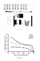
- FIG. 15 illustrate an experimental test set-up and resulting radial compressive stress strain curves of two stent prototypes
- FIG. 16 is a block diagram of a memory having stored thereon program code for designing a stent lattice cell, in accordance with an embodiment.
- stents can be classified into balloon expanding (BE) or self expanding (SE).
- BE stents which are manufactured in the form of a tube with a radius smaller than the target vessel, are deployed using a retractable inflatable balloon. After the balloon deflates and retracts, the stent structure plastically deforms and preserves its deployed shape.
- SE structures are manufactured from tubes with a diameter larger than that of the target vessel. For delivery and insertion purposes, the structure is compressed elastically into the smaller diameter of the delivery catheter, which is then inserted percutaneously into the body. Upon reaching the desired position, the casing sheath is removed and the stent elastically deploys to its original shape.
- FIGS. 1 a -1 f illustrate some prior art stent devices which are designed to deploy into a body by minimally invasive percutaneous intervention, namely a self-expanding CoreValveTM stent device, a SymetisTM W aortic stent valve, a ViatorrTM stent-graft, a WallstentTM Cobalt SE stent, a SMARTTM Nitinol SE stent, and a diamond-cell stent.
- a self-expanding CoreValveTM stent device namely a self-expanding CoreValveTM stent device, a SymetisTM W aortic stent valve, a ViatorrTM stent-graft, a WallstentTM Cobalt SE stent, a SMARTTM Nitinol SE stent, and a diamond-cell stent.
- FIG. 1 f illustrates the structural geometry of a diamond-cell stent with closed lattice cells.
- Each lattice cell has an uneven shape, the boundaries curves having abrupt changes in geometry. This curvature discontinuity at the blending points between the arc geometric primitives of the stent and the linear segments generate stress concentration that may increase significantly the level of stress.
- Shape, size, topology and thickness of a stent lattice cell are geometric variables that may be tailored to improve fatigue life and mechanical performance of stent structures, either BE or SE.
- a design method for the shape synthesis of smooth cell geometry that can yield a lattice stent having reduced stress concentration, thereby reducing its risk of fatigue failure, and a stent lattice structure produced by such a design method.
- a design strategy to synthesize the cell shape of a two-dimensional lattice for SE stents. Results obtained by the application of the design method are compared with the characteristics of an existing Nitinol SE graft commonly used in abdominal aortic aneurisms repair.
- the effect of selected geometric parameters e.g. tube thickness, strut width, and number of lattice cells, on stent fatigue life are presented.
- stents may undergo nearly 4 ⁇ 10 8 cycles of alternating forces arising from pulsating blood pressure and body movement. Such a loading condition could potentially lead to fatigue failure, especially for stents made of Nitinol, which has a lower resistance to fatigue crack growth in comparison to other metals.
- each lattice cell are G 2 -continuous, in a manner similar to that described by Teng et al. in “Shape Synthesis in Mechanical Design” (Teng et al., Acta Polytechnica, Vol. 47, No. 6, pp. 56-62, 2008), the entire content of which is incorporated herein by reference.
- each of the cell members be G 2 -continuous at the blending points between the geometric primitives defining a cell as well as at the points interconnecting adjacent cells, and then be as straight as possible, i.e. with the smallest possible curvature, to avoid high bending moments caused by curved cell members.
- FIG. 2 illustrates two possible examples of unit cells 10 and 12 of a stent lattice cell having a shape which is formed by curves that are continuous in their curvature and therefore which have boundaries that are G 2 -continuous. While these two shapes are depicted, other shaped cells which adhere to the presently described method and system for determining the shape of the lattice cells are also possible. For example, a diamond shaped lattice cell having rounded corners may also be determined and formed as described herein.
- the lattice cells of FIG. 2 are formed of a number of geometric primitives which are connected by blending points, the cells being G 2 -continuous at the blending points between the geometric primitives as well as at the points interconnecting adjacent cells.
- Each of the geometric primitives therefore begin with a common radius of curvature, and are then optimized as described herein in order to minimize the curvature as much as possible by making them as straight as possible (i.e. with the smallest possible curvature).
- the unit cell 10 , 12 is replicated along two directions in a planar sheet to form a stent lattice, which is then folded into a cylindrical 3D surface forming a lattice cylinder.
- the lattice cylinder is described by n c cells in the circumferential direction and n l cell rows in the longitudinal direction.
- the tube thickness and strut width are respectively t and w. Due to similarity with the diamond and super-ellipse shapes, the cell topologies 10 and 12 illustrated in FIG. 2 are referred to as “D cell” and “E cell” hereinafter, respectively.
- FIG. 3 illustrates one embodiment of a design method 20 for optimizing the shape of a stent lattice cell.
- the design method is based on the synthesis of structural members with G 2 -continuous curves that minimize the root mean square of the cell curvature.
- the first step 22 consists in generating a unit cell model representing a stent cell and having a substantially G 2 -continuous curvature.
- a weighting coefficient representing a contribution of the blending points to the curvature of an optimal curve is set to a same value for each point.
- the curvature is expressed as a function of the weighting factors having the same value.
- a geometry optimization is performed, i.e. the curvature is minimized.
- the geometry optimization consists in minimizing only the root mean square (rms) value of the curvature of the cell geometric primitives.
- steps 24 , 26 , and 27 the material properties and pseudo-elastic behavior of Nitinol are ignored.
- a structure optimization of the unit cell using the attributes and stress-strain curve of the stent material to be factored is performed.
- the structure optimization consists in iteratively determining a variable value for the weighting factor value for the blending points using stress and/or strain characteristics for the stent material, expressing the curvature as a function of the variable values, and minimizing the curvature.
- strain-based weighting factor was used in at least one embodiment of the presently disclosed method, and more particularly given the selection of Nitirol as the material of the lattice in the embodiment in question, it is also possible to use a stress-based weighting factor.
- the shape synthesis of the lattice strut is stated as follows: under given end conditions, find a boundary-curve ⁇ that connects two given end blending points A and B of the cell strut as smoothly as possible and with a G 2 -continuous curve.
- the optimization problem may be formulated as:
- J ⁇ ( ⁇ ) 1 L ⁇ ⁇ A B ⁇ ⁇ 2 ⁇ d s -> min ⁇ ⁇ ( s ) ( 1 )
- ⁇ square root over (J) ⁇ is the rms value of the curvature
- k of a cell member boundary-curve
- L is the member length
- a and B are its end-blending points
- ds is the arc-length along the member, starting from 0 at point A, as shown in FIG. 2 .
- the member boundary-curve is subjected to four constraints at each end-point: two constrain the end-blending points of each curve of the lattice cell, while the other set the tangent and curvature of the curve at these blending points.
- Equation 1 can be treated as a problem of mathematical programming by means of non-parametric cubic splines.
- each boundary curve is discretized by n+2 supporting blending points ⁇ P k ⁇ 0 n+1 that are defined by P k ( ⁇ k , ⁇ k ) in a polar coordinate system.
- equation 1 can be written as:
- z ⁇ ( x ) 1 n ⁇ ⁇ 1 n ⁇ w k ⁇ ⁇ k 2 -> min x ( 7 )
- w k is the weighting coefficient of point k th defined at each supporting point, and representing the contribution of each point to the curvature of the optimum curve.
- Z(x) therefore represents the discretization of the functional equation given in Equation 1.
- the curvature at each point P k is given by:
- ⁇ k ⁇ k 2 + 2 ⁇ ( ⁇ k ′ ) 2 ⁇ _ ⁇ k ⁇ ⁇ k ′′ ( ⁇ k 2 + ( ⁇ k ′ ) 2 ) 3 / 2 ( 8 )
- step 24 of geometry optimization assumes equal weighting coefficients, i.e. 1/n to find a geometrically optimum boundary of the unit cell, whereby several iterations may be performed as part of the design optimization in order to find the minimum curvature desired.
- This result is then further optimized at step 26 , in which the stress and strain regimes are taken into account.
- the expressions of the weighting coefficients, w k (see equation 7) are considered as a function of the strain regime obtained iteratively at each finite element analysis (FEA) iteration.
- the stent is to be made of Nitinol
- strain is considered rather than stress, since the plateau region of the Nitinol stress-strain curve is much more sensitive to strain changes, as illustrated in FIG. 4 .
- the weight coefficients are therefore not uniform along the cell strut boundary-curve and they are defined as:
- ⁇ k and ⁇ T are, respectively, the rms value of the von Mises strain at the k th supporting point of the profile curve, and the rms value of the strain over the whole cell element of the stent and are defined as:
- ⁇ i is the von Mises strain at i th node
- ⁇ ki is the von Mises strain of the ⁇ k nodes (2% of the total nodes of FE model for example), which are relatively closer to the k th supporting point.
- the structural optimization algorithm is set to end when the reduction in the maximum strain value is smaller than a predetermined value such as 0.1% for example.
- the stent may be made from materials other than Nitinol.
- the stent may be formed of 316L stainless steel, cobalt-chromium-nickel-molybdenum, iron alloy, tantalum, or a plastic such as polyethylene or polyurethane.
- the choice of material for the stent will depend on the application and intended use of the stent. For each of these materials, the stress-strain characteristics will differ. While in the present example where the material selected is Nitinol, weight factors were calculated based on strain because Nitinol is much more sensitive to strain in the plateau region as seen in FIG. 4 . With other materials, however, the weight coefficient, as shown in Equations 9 and 10 above, can alternately be calculated through stresses instead.
- the above described method for generating a stent cell shape may be converted to a method for generating a shape for the stent by performing two further steps consisting in replicating the unit cell obtained via the method 20 to form a stent lattice, and folding the stent lattice to form a substantially cylindrical 3D surface which corresponds to the desired stent structure.
- Nitinol stent grafts have been successfully and widely employed in endovascular repair for abdominal aortic aneurisms (AAAs).
- AAAs abdominal aortic aneurisms
- the success of aneurism repairs, however, is often undermined by issues entailing stent-graft fatigue, graft migration, and blood leakage into the aneurysm cavity. It has been shown that two strategies may be adopted to reduce these risks. The first one is to stiffen the stent in the radial direction, thereby reducing the risk of endovascular leakage and device migration. The second one is to reduce the level of the alternating strain generated by a pulsating blood pressure with the objective of lowering the risk of fatigue failure.
- the design method 20 is applied to optimize both the radial stiffness and fatigue life of a stent.
- the obtained stent is compared to a benchmark stent design by assuming a stent total length of 100 mm and a non-shrunk diameter of 30 mm.
- the risk of fatigue failure is expressed by a fatigue safety factor, obtained by dividing the 0.4% Nitinol endurance limit by the maximum alternating strain of the stent.
- the sensitivity of the radial stiffness and fatigue safety factor to the change of selected parameters defining stent geometry is studied.
- ANSYSTM finite element modeling (FEM) software was used to analyze the radial size reduction occurring during the delivery process of the stent and the contact between the stent and the arterial wall after stent-graft deployment.
- FEM finite element modeling
- Nitinol is a pseudo-elastic material extensively used in biomedical devices for its bio-compatibility, shape memory property besides outstanding ability to withstand severe deformation.
- FIG. 4 illustrates a schematic view of the stress-strain curve of Nitinol at a given temperature.
- Auricchio F (1995) “Shape Memory Alloys: Applications, Micromechanics, Macromodeling and Numerical Simulations”, University of California at Berkely, was used. The following material attributes were assumed:
- E is the Young's modulus and v is the Poisson ratio while the indices A and M refer to the austenite and martensite phases.
- the structure of the artery wall is assumed to be incompressible with a Young's modulus of 1.2 MPa and a Poisson's ratio of 0.495, as prescribed by FDA protocols (ASTM 2007).
- the loading conditions include shrinking loading conditions and sealing loading conditions.
- the stent-graft with a deployed outer diameter of 30 mm must first be shrunk to fit into the 24F delivery sheath and then, when deployed, must regain its original shape.
- the shrinking maneuver is modeled by applying a radial displacement to a rigid movable surface, which is in frictionless contact with the strut outer surface.
- the graft material has been assumed to have a negligible effect on the overall behavior of stent in the sealing section; thus the graft was not considered in the model.
- the stent should be anchored to the neck artery of the abdominal aortic aneurism (AAA) after its release from the deployment system.
- AAA abdominal aortic aneurism
- the anchoring force should be sufficiently high to prevent the stent-graft migration.
- the stent deployment was modeled in two steps. First, the stent was shrunk to a diameter close to the artery interior wall by using rigid contact surface. Second, the stent expanded to reach an equilibrium radius in contact with the artery wall by gently removing the contact surface of the rigid body. The diastolic and systolic blood pressures were modeled as constant pressures applied to the inner surface of the artery wall.
- FIGS. 5 and 6 illustrate the results of minimizing the curvature of the inner boundary-profile for the D lattice cell and the E lattice cells, respectively.
- the initial geometric primitives 30 and 32 of the unit cell are G 2 -continuous.
- the curves 34 and 36 represent the geometric optima obtained by minimizing the curvature while assuming constant weighting factors.
- the curves 38 and 40 are the structural optimum solutions obtained by iteratively minimizing the curvature with variable weighting factors, each updated according to equation (9) with respect to the FEA results.
- the structural optimization significantly changes the boundary-profile of the geometrically optimized D cell, whereas it has a negligible effect on the boundary-profile of the E cell.
- FIGS. 7 a and 7 b illustrate a straight row of optimized cells, a row folded into cylinder, and an assembly of three folded rows of optimized cells for the D and E cell geometries, respectively.
- FIGS. 8 a - b and 9 a - b illustrate the von Mises strain distribution in the shrunk stent with E and D lattice cells. Since the maximum strain level in the shrunk lattice is below the 12% recoverable strain limit of Nitinol, the proposed cell geometries are fully deployable. The distribution of the first principal strain in the deployed D and E stents are illustrated in FIGS. 8 c and 9 c . Table 1 shows the performance of the proposed designs in comparison with an R stent design.
- FIGS. 8 d and 9 d illustrate the von Mises stress distribution induced in the artery wall after graft deployment.
- the stress level in the artery wall is below 0.67 MPa, the elastic limit of the artery.
- the level of von Mises stress induced in the artery wall by D(E) cell geometries exhibits a 38% (52%) increase.
- FIG. 10 illustrates the radial supportive force as a function of the outer diameter for E and D stents in comparison with the R stent for a prescribed stent area and tube thickness.
- the proposed D (E) cell designs provide 82% (165%) increase in the supportive radial force.
- FIG. 11 summarizes the results.
- the application of the proposed methodology enables to find a lattice design with a higher fatigue safety factor and an improved radial supportive force.
- the radial supportive force for D (E) cell enhances respectively by 2.3% (1.4%), 10% (18.55%), 16.9% (7.39%), and 7.91% (2.11%).
- the fatigue safety factor improves by 0.46% (49.7%), 64.13% (45.5%), 33% (50.7%), and 32.6% (41.6%).
- the stent area also increases by 19.1% (14.7%), 8.9% (14.8%), 21.4% (16.1%) and 0% (0%).
- the above benefits come along with a side-effect, i.e. an increase of the level of von Mises stress induced in the artery wall by 45% (36%) for D (E) cell. This is caused by the higher radial supportive force applied by the sharp edges of the stent struts in contact with the artery wall. Despite the stress increase in the artery wall, however, the contact stress distribution induced by D and E cells on the artery wall is more uniform. Furthermore, this stress level can be easily reduced by rounding the sharp fillet of the strut edges of the stent in contact with the artery.
- n c The impact of the number of cells in the circumferential direction, n c is illustrated in FIGS. 11 a -11 c .
- the stent area shows a rapid linear increase.
- the fatigue safety factor decreases if n c reduces, as opposed to D stent. Therefore, the D lattice should be preferred for smaller values of n c , whereas higher values of n c should be chosen for the E lattice provided the deployment constraint is met (see FIG. 11 a ).
- reducing n c is not always beneficial. Rather, a low n c might have two effects. First, it might enhance the stress level in the artery wall. Second, it might increase the risk of the tissue to prolapse into the inner area of the lattice cell, illustrated in FIGS. 5 and 6 as the “O region”.
- FIGS. 11 d -11 f illustrate the influence of the number of cells, n l , in the longitudinal direction on radial force, fatigue life and stent area.
- An increase of n l results in a substantial reduction of the level of radial supportive force. This is because for a given arterial length, e.g. 100 mm, the radial force exerted on the artery is distributed more uniformly in stents with higher n l ; thus the involvement of a larger number of cell rows makes lower the share of the radial load.
- the stiffness of a stent increases if the length of each cell row is shortened, thereby reducing the amplitude of the alternating stress and improving fatigue life.
- the fatigue safety factor and the stent area increase proportionally with n l .
- FIGS. 11 g and 11 j illustrate that thickening the strut thickness and width is beneficial for both stent radial stiffness and radial supportive force. Besides these gains, a stiffer stent would be also more resistant to the deformation imposed by a pulsatile pressure, thereby reducing the alternating strain experienced by its members. This is observed in FIGS. 11 h and 11 k , where the fatigue safety factor of both D and E lattices increases linearly with w and t.
- FIG. 11 i shows that the stent area is not affected by any change of the stent thickness as opposed to the trend observed by varying n c , n l , w in FIGS. 11 c , 11 f , and 11 l.
- FIG. 11 g should, however, be taken with caution since both the artery contact stress and the role of blood flow play an important role. A thicker strut will cause a higher contact stress in the artery wall. Blood flow in proximity with the artery wall and the artery wall will affect the selection of the strut thickness. Both these issues should be determined through multi-disciplinary analysis and optimization involving both computational fluid dynamics and structural analysis.
- FIG. 11 a -11 g show that D and E cells are stiffer in the radial direction and have a higher fatigue life with respect to the reference stent design.
- a drawback of these cells is the risk of tissue prolapsing inside the artery wall. This phenomenon would occur in the “O region” depicted in FIG. 7 for D and E cells. These regions result from the selection of the cell shape besides from the fulfillment of the requirement for stent deployment, which imposes an upper limit on the maximum number of nc.
- the problem of prolapsed tissue may be solved by combining the E and D cells into a hybrid cell shape. Two geometric primitives of the D cell are assembled with two of the E cell. FIGS.
- stent radial supportive force, fatigue failure safety factor, and stress level in the artery wall may have conflicting outcomes.
- An improvement of one may penalize the other. It may, thus, be necessary to formulate the shape synthesis of the lattice cell within a multi-objective optimization framework, which would provide trade-off solutions among conflicting objective functions, such as those identified above.
- the present design methodology based on shape optimization improves the fatigue safety factor and increases the radial supportive force of Nitinol self-expandable stents with close cell geometry.
- shape of the lattice cell has been synthesized with geometric primitives of continuous curvature. The bending moments caused by curved cell members are reduced by minimizing their curvature with the goal of making them as straight as possible.
- the method has been applied to optimize the cell shape of a lattice Nitinol stent-graft.
- Two novel cell geometries have been synthesized; their radial supportive force and fatigue safety factor have been studied through a FEA parametric study.
- the results have shown an improvement of stent anchoring performance and a reduction of the risk of fatigue failure.
- the potential risk of prolapsed tissue has been identified and a solution of a hybrid design that combines the proposed lattice cells has been proposed. Further work is required to reduce the level of von Mises stress induced in the artery wall as well as to optimize simultaneously radial supportive force, fatigue safety factor and stress level of the artery wall.
- FIG. 13 illustrates one embodiment of a system 50 for generating the shape of a stent lattice cell.
- the system 50 comprises a unit cell generator 52 for generating a unit cell model representing a stent cell using the above described method, a geometry optimization module 54 for optimizing the geometry of the stent cell using the above described method, and a structural optimization module 56 for optimizing the structure of the geometrically optimizing stent cell using the above described method.
- finite element (FE) models of AAA stent-grafts with sharp-corner diamond see FIG. 14 a ), rounded diamond (see FIG. 14 b ), and superellipse (see FIG. 14 c ) unit cells were developed.
- the rounded diamond and superellipse unit cells were optimized as described above, while the sharp-corner diamond unit cell was set as a benchmark.
- the FE models demonstrate that the proposed methodology for synthesizing a stress concentration-free cell with the superelliptical shape of FIG.
- FIG. 14 c results in a 84.1% improvement in the fatigue safety factor and an 95% increase in the radial outward force per unit of stent area, as compared to the baseline sharp-corner diamond cell design of FIG. 14 a .
- the FE models further demonstrate that using the rounded diamond shape of FIG. 14 b results in a 26.4% improvement in the fatigue safety factor and a 60% increase in the radial outward force per unit of stent area, as compared to the baseline sharp-corner diamond cell design.
- the FE results pertaining to the radial outward force were qualitatively confirmed by compression testing, which was performed on sharp-corner and rounded diamond prototypes made of VeroWhitePlusTM resin by 3D printing.
- the FE models and mechanical testing results indicate that the fatigue life and stent fixation of the proposed designs are likely to outperform those of existing designs.
- system 50 may be further configured for generating the shape of the whole stent.
- system 50 further comprises a stent generator adapted to replicate the optimized stent cell output by the structural optimization module 56 to form a stent lattice and fold the stent lattice to form a substantially cylindrical 3D surface in order to obtain a stent structure which is output.
- FIG. 16 illustrates one embodiment of a memory 80 having stored therein program code 82 of a unit cell model generator for generating a unit cell model representing a stent cell using the above described method, program code 84 of a geometry optimization module for optimizing the geometry of the stent cell using the above described method, and program code 86 of a structural optimization module for optimizing the structure of the geometrically optimizing stent cell using the above described method.
- the program codes 82 , 84 , and 86 are to be executed by a processing unit 88 such as the processor of a computer for example.
- the memory 80 may further comprise program code of a stent generator (not shown) for replicating the optimized stent cell to form a stent lattice and fold the stent lattice to form a substantially cylindrical 3D surface in order to obtain a stent structure.
- the memory 80 may also have stored therein program code of a lattice geometry optimization unit (not shown) for finding the coating material thickness and profile optimum for maximizing the strength of the stent-coating interface. Using such a coating material, the risk of delamination or failure of the stent coating can be minimized.
Abstract
Description
where √{square root over (J)} is the rms value of the curvature, k, of a cell member boundary-curve, L is the member length, A and B are its end-blending points, and ds is the arc-length along the member, starting from 0 at point A, as shown in
ρ(θ)=A k(θ−θk)3 +B k(θ−θk)2 +C k(θ−θk)2 +D k (3)
ρ=[ρ0,ρ1, . . . ρn,ρn+1]T
ρ′=[ρ′0,ρ′1, . . . ρ′n,ρ′n+1]T
ρ″=[ρ″0,ρ″1, . . . ρ″n,ρ″n+1]T (4)
Aρ″=6Cp and Pρ′=Qρ (5)
where A, C, P, and Q are defined as follows.
With tA=tan γA and tB=tan γB, where γA and γB are the tangent angles made by the tangent to the curve with the radius vector at the end-points A and B, as shown in
Furthermore, ρ0=ρA and ρn+1=ρB are known from a given parameter vector of the cell. Now, if x is the vector of the design variables, defined as
x=[ρ1, . . . ρn]T (6).
where wk is the weighting coefficient of point kth defined at each supporting point, and representing the contribution of each point to the curvature of the optimum curve. Z(x) therefore represents the discretization of the functional equation given in
where
| TABLE 1 | |||||
| Maximum | |||||
| Radial force at | Fatigue safety | Wall stress | shrunk | ||
| 100 mmHg (N) | factor | (MPa) | strain (%) | ||
| D cell | 3.17 | 3.21 | 0.403 | 10.6 |
| E cell | 3.315 | 3.70 | 0.367 | 10.85 |
| R cell | 1.7 | 2.01 | 0.265 | 8.86 |
Claims (22)
Priority Applications (1)
| Application Number | Priority Date | Filing Date | Title |
|---|---|---|---|
| US13/659,398 US9492296B2 (en) | 2011-10-25 | 2012-10-24 | Stent devices made of a lattice with smooth shape cells improving stent fatigue life |
Applications Claiming Priority (2)
| Application Number | Priority Date | Filing Date | Title |
|---|---|---|---|
| US201161551096P | 2011-10-25 | 2011-10-25 | |
| US13/659,398 US9492296B2 (en) | 2011-10-25 | 2012-10-24 | Stent devices made of a lattice with smooth shape cells improving stent fatigue life |
Publications (2)
| Publication Number | Publication Date |
|---|---|
| US20140114430A1 US20140114430A1 (en) | 2014-04-24 |
| US9492296B2 true US9492296B2 (en) | 2016-11-15 |
Family
ID=50486047
Family Applications (1)
| Application Number | Title | Priority Date | Filing Date |
|---|---|---|---|
| US13/659,398 Expired - Fee Related US9492296B2 (en) | 2011-10-25 | 2012-10-24 | Stent devices made of a lattice with smooth shape cells improving stent fatigue life |
Country Status (1)
| Country | Link |
|---|---|
| US (1) | US9492296B2 (en) |
Cited By (1)
| Publication number | Priority date | Publication date | Assignee | Title |
|---|---|---|---|---|
| US10527027B2 (en) | 2017-02-15 | 2020-01-07 | Delavan Inc. | In-situ stress control in structures |
Families Citing this family (2)
| Publication number | Priority date | Publication date | Assignee | Title |
|---|---|---|---|---|
| US20200390569A1 (en) * | 2017-10-13 | 2020-12-17 | Efemoral Medical, Inc. | Absorbable intravascular devices that provide a decrease in radial rigidity of the vessel over time |
| CN111708327B (en) * | 2020-07-14 | 2023-07-11 | 中国石油大学(华东) | PH spline transition linear path processing method with G2 continuity |
Citations (15)
| Publication number | Priority date | Publication date | Assignee | Title |
|---|---|---|---|---|
| US5636338A (en) * | 1993-01-29 | 1997-06-03 | Silicon Graphics, Inc. | Method for designing curved shapes for use by a computer |
| US5928246A (en) | 1997-10-15 | 1999-07-27 | Bsc Northwest Technology Center, Inc. | Stent securing catheter |
| US20010044652A1 (en) * | 1999-10-14 | 2001-11-22 | Moore Brian Edward | Stents with multi-layered struts |
| WO2004049973A1 (en) | 2002-11-29 | 2004-06-17 | Vascular Interventional Technologies Inc. | Embolus blood clot filter |
| US20040225346A1 (en) * | 2003-02-05 | 2004-11-11 | Mazumder Mark M. | Encased stent |
| US20050096733A1 (en) * | 2001-12-29 | 2005-05-05 | Kovneristy July K. | Stent and method for the production thereof (variants) |
| US20060136037A1 (en) * | 2004-10-14 | 2006-06-22 | Debeer Nicholas C | Small vessel stent designs |
| US20060264810A1 (en) | 2005-04-21 | 2006-11-23 | Hattler Brack G | Percutaneous respiratory assist catheter incorporating a spinning fiber bundle |
| US20080188924A1 (en) * | 2002-04-01 | 2008-08-07 | Advanced Cardiovascular Systems, Inc. | Hybrid stent and method of making |
| US20080221666A1 (en) * | 2006-12-15 | 2008-09-11 | Cardiomind, Inc. | Stent systems |
| US20090099644A1 (en) * | 2007-09-05 | 2009-04-16 | Baylis Medical Company Inc. | Covered stent |
| US20100049300A1 (en) * | 2008-08-19 | 2010-02-25 | Biotronik Vi Patent Ag | Stent and Method and Device for Fabricating the Stent |
| US7735449B1 (en) | 2005-07-28 | 2010-06-15 | Advanced Cardiovascular Systems, Inc. | Stent fixture having rounded support structures and method for use thereof |
| US20110276123A1 (en) * | 2007-11-27 | 2011-11-10 | Davies Peter F | Vascular stent design |
| US20120303112A1 (en) * | 2011-01-14 | 2012-11-29 | Armstrong Joseph R | Stent |
-
2012
- 2012-10-24 US US13/659,398 patent/US9492296B2/en not_active Expired - Fee Related
Patent Citations (16)
| Publication number | Priority date | Publication date | Assignee | Title |
|---|---|---|---|---|
| US5636338A (en) * | 1993-01-29 | 1997-06-03 | Silicon Graphics, Inc. | Method for designing curved shapes for use by a computer |
| US5928246A (en) | 1997-10-15 | 1999-07-27 | Bsc Northwest Technology Center, Inc. | Stent securing catheter |
| US20010044652A1 (en) * | 1999-10-14 | 2001-11-22 | Moore Brian Edward | Stents with multi-layered struts |
| US20050096733A1 (en) * | 2001-12-29 | 2005-05-05 | Kovneristy July K. | Stent and method for the production thereof (variants) |
| US20080188924A1 (en) * | 2002-04-01 | 2008-08-07 | Advanced Cardiovascular Systems, Inc. | Hybrid stent and method of making |
| WO2004049973A1 (en) | 2002-11-29 | 2004-06-17 | Vascular Interventional Technologies Inc. | Embolus blood clot filter |
| US20040225346A1 (en) * | 2003-02-05 | 2004-11-11 | Mazumder Mark M. | Encased stent |
| US20060136037A1 (en) * | 2004-10-14 | 2006-06-22 | Debeer Nicholas C | Small vessel stent designs |
| US20060264810A1 (en) | 2005-04-21 | 2006-11-23 | Hattler Brack G | Percutaneous respiratory assist catheter incorporating a spinning fiber bundle |
| US7735449B1 (en) | 2005-07-28 | 2010-06-15 | Advanced Cardiovascular Systems, Inc. | Stent fixture having rounded support structures and method for use thereof |
| US20080221666A1 (en) * | 2006-12-15 | 2008-09-11 | Cardiomind, Inc. | Stent systems |
| US20090099644A1 (en) * | 2007-09-05 | 2009-04-16 | Baylis Medical Company Inc. | Covered stent |
| US20110276123A1 (en) * | 2007-11-27 | 2011-11-10 | Davies Peter F | Vascular stent design |
| US20100049300A1 (en) * | 2008-08-19 | 2010-02-25 | Biotronik Vi Patent Ag | Stent and Method and Device for Fabricating the Stent |
| US20120214384A1 (en) * | 2008-08-19 | 2012-08-23 | Biotronik Vi Patent Ag | Stent and Method and Device for Fabricating the Stent |
| US20120303112A1 (en) * | 2011-01-14 | 2012-11-29 | Armstrong Joseph R | Stent |
Non-Patent Citations (4)
| Title |
|---|
| B. B Barsky and T. DeRose, "Geometric Continuity of Parametric Curves," Berkely Computer Graphics Laboratory, Computer Science Division, Dept. of EE and CS, University of California, Berkely, Technical Report No. UCB/CSD 84/205, Oct. 1984. * |
| C. P. Teng, S. Bai, J. Angeles, "Shape Synthesis in Mechanical Design", pp. 1-10, 2008. * |
| D. Stoeckel, C. Bonsignore and S. Duda, A Survey of Stent Designs, NDC, Min Invas Ther & Allied Technol 11 (4), pp. 137-147, 2002, Fremont, California, USA. |
| Teng et al., "Shape Synthesis in Mechanical Design," Acta Polytechnica, vol. 47, No. 6, pp. 56-62, 2008. * |
Cited By (1)
| Publication number | Priority date | Publication date | Assignee | Title |
|---|---|---|---|---|
| US10527027B2 (en) | 2017-02-15 | 2020-01-07 | Delavan Inc. | In-situ stress control in structures |
Also Published As
| Publication number | Publication date |
|---|---|
| US20140114430A1 (en) | 2014-04-24 |
Similar Documents
| Publication | Publication Date | Title |
|---|---|---|
| JP6053884B2 (en) | Grafts with high fatigue resistance, graft delivery systems, and methods of use | |
| Azaouzi et al. | Deployment of a self-expanding stent inside an artery: a finite element analysis | |
| Abad et al. | Shape optimization of stress concentration-free lattice for self-expandable Nitinol stent-grafts | |
| Douglas et al. | Analyses and design of expansion mechanisms of balloon expandable vascular stents | |
| EP1129673A2 (en) | Longitudinally flexible stent | |
| US11364135B2 (en) | Stent | |
| KR102195532B1 (en) | Stent | |
| Zhao et al. | Performance of self-expanding Nitinol stent in a curved artery: impact of stent length and deployment orientation | |
| US9492296B2 (en) | Stent devices made of a lattice with smooth shape cells improving stent fatigue life | |
| Jayendiran et al. | Computational analysis of Nitinol stent-graft for endovascular aortic repair (EVAR) of abdominal aortic aneurysm (AAA): Crimping, sealing and fluid-structure interaction (FSI) | |
| Puértolas et al. | A methodology for the customized design of colonic stents based on a parametric model | |
| Liu et al. | Structure design of vascular stents | |
| Liu et al. | Thoracic aorta stent grafts design in terms of biomechanical investigations into flexibility | |
| Beyi et al. | Stent classifications and effect of geometries on stent behaviour using finite element method | |
| CN113065264B (en) | Cross-support spiral popliteal artery stent and manufacturing method thereof | |
| CA2793650A1 (en) | Stent devices made of a lattice with smooth shape cells improving stent fatigue life | |
| Jung et al. | Finite element structural analysis of self-expandable stent deployment in a curved stenotic artery | |
| Douglas | Design of stent expansion mechanisms | |
| Shankaran et al. | Parameterization and optimization of balloon expandable stent | |
| Khan | Design optimisation for stent manufacture | |
| Ardatov et al. | Deformation characteristics of coronary stents of the matrix and continuous sinusoidal types in free expansion: Computer simulation | |
| Ghosh et al. | Numerical Study on Mechanical Properties of stents with different materials during stent deployment with balloon expansion | |
| Gupta et al. | A novel double arrowhead auxetic coronary stent | |
| Kalra | Study of coronary stent deformation using finite element method | |
| Schiavone et al. | Modelling of stent deployment and deformation in diseased arteries by considering vessel anisotropy |
Legal Events
| Date | Code | Title | Description |
|---|---|---|---|
| AS | Assignment |
Owner name: THE ROYAL INSTITUTION FOR THE ADVANCEMENT OF LEARN Free format text: ASSIGNMENT OF ASSIGNORS INTEREST;ASSIGNORS:PASINI, DAMIANO;ABAD, EHSAN MASOUMI KHALIL;SIGNING DATES FROM 20111026 TO 20111101;REEL/FRAME:029204/0035 |
|
| STCF | Information on status: patent grant |
Free format text: PATENTED CASE |
|
| FEPP | Fee payment procedure |
Free format text: MAINTENANCE FEE REMINDER MAILED (ORIGINAL EVENT CODE: REM.); ENTITY STATUS OF PATENT OWNER: SMALL ENTITY |
|
| LAPS | Lapse for failure to pay maintenance fees |
Free format text: PATENT EXPIRED FOR FAILURE TO PAY MAINTENANCE FEES (ORIGINAL EVENT CODE: EXP.); ENTITY STATUS OF PATENT OWNER: SMALL ENTITY |
|
| STCH | Information on status: patent discontinuation |
Free format text: PATENT EXPIRED DUE TO NONPAYMENT OF MAINTENANCE FEES UNDER 37 CFR 1.362 |
|
| FP | Expired due to failure to pay maintenance fee |
Effective date: 20201115 |