US9489899B2 - Control circuit for continuous smooth reduction of backlight luminance, and a display thereof - Google Patents
Control circuit for continuous smooth reduction of backlight luminance, and a display thereof Download PDFInfo
- Publication number
- US9489899B2 US9489899B2 US14/459,498 US201414459498A US9489899B2 US 9489899 B2 US9489899 B2 US 9489899B2 US 201414459498 A US201414459498 A US 201414459498A US 9489899 B2 US9489899 B2 US 9489899B2
- Authority
- US
- United States
- Prior art keywords
- value
- video signal
- coefficient
- gradation
- luminance
- Prior art date
- Legal status (The legal status is an assumption and is not a legal conclusion. Google has not performed a legal analysis and makes no representation as to the accuracy of the status listed.)
- Active
Links
Images


Classifications
-
- G—PHYSICS
- G09—EDUCATION; CRYPTOGRAPHY; DISPLAY; ADVERTISING; SEALS
- G09G—ARRANGEMENTS OR CIRCUITS FOR CONTROL OF INDICATING DEVICES USING STATIC MEANS TO PRESENT VARIABLE INFORMATION
- G09G3/00—Control arrangements or circuits, of interest only in connection with visual indicators other than cathode-ray tubes
- G09G3/20—Control arrangements or circuits, of interest only in connection with visual indicators other than cathode-ray tubes for presentation of an assembly of a number of characters, e.g. a page, by composing the assembly by combination of individual elements arranged in a matrix no fixed position being assigned to or needed to be assigned to the individual characters or partial characters
- G09G3/34—Control arrangements or circuits, of interest only in connection with visual indicators other than cathode-ray tubes for presentation of an assembly of a number of characters, e.g. a page, by composing the assembly by combination of individual elements arranged in a matrix no fixed position being assigned to or needed to be assigned to the individual characters or partial characters by control of light from an independent source
- G09G3/3406—Control of illumination source
-
- G—PHYSICS
- G09—EDUCATION; CRYPTOGRAPHY; DISPLAY; ADVERTISING; SEALS
- G09G—ARRANGEMENTS OR CIRCUITS FOR CONTROL OF INDICATING DEVICES USING STATIC MEANS TO PRESENT VARIABLE INFORMATION
- G09G2320/00—Control of display operating conditions
- G09G2320/06—Adjustment of display parameters
- G09G2320/0626—Adjustment of display parameters for control of overall brightness
- G09G2320/064—Adjustment of display parameters for control of overall brightness by time modulation of the brightness of the illumination source
-
- G—PHYSICS
- G09—EDUCATION; CRYPTOGRAPHY; DISPLAY; ADVERTISING; SEALS
- G09G—ARRANGEMENTS OR CIRCUITS FOR CONTROL OF INDICATING DEVICES USING STATIC MEANS TO PRESENT VARIABLE INFORMATION
- G09G2320/00—Control of display operating conditions
- G09G2320/06—Adjustment of display parameters
- G09G2320/0626—Adjustment of display parameters for control of overall brightness
- G09G2320/0646—Modulation of illumination source brightness and image signal correlated to each other
-
- G—PHYSICS
- G09—EDUCATION; CRYPTOGRAPHY; DISPLAY; ADVERTISING; SEALS
- G09G—ARRANGEMENTS OR CIRCUITS FOR CONTROL OF INDICATING DEVICES USING STATIC MEANS TO PRESENT VARIABLE INFORMATION
- G09G2360/00—Aspects of the architecture of display systems
- G09G2360/16—Calculation or use of calculated indices related to luminance levels in display data
Definitions
- the present invention relates to a control circuit and a display device thereof.
- it relates to the control circuit and the display device thereof applied to various display devices such as data processor.
- B/L low power consumption devices
- a value of B/L power consumption as related to total power consumption is still large when a display device or the like is used in the always on lighting condition.
- CABC Content Adaptive Brightness Control
- the CABC driving circuit it is required to calculate the feature value of video signal in one frame in order to determine an amount of the reduction of B/L luminance.
- the feature value of video signal is a value for changing the B/L luminance, the value is designed to affect an image quality.
- this method is designed to represent a gradation value of the video signal of each pixel in one frame as a histogram and reduce the B/L luminance according to the histogram data.
- the video signal and the maximal gradation will be described as 8 bit and 255th gradation, respectively.
- Image A is supposed to represent 30 percentage of white window (255th gradation) in black screen (0 gradation), and
- Image B is supposed to represent 29 percentage of white window (255th gradation) in black screen (0 gradation).
- the Image A is supposed to set the gradation falling on 30 percentage of total numbers, counting from the maximal gradation as 255th gradation
- the Image B is supposed to set the gradation falling on 30 percentage of total numbers, counting from the maximal gradation as 0 gradation.
- the Image A is an amount of luminance reduction based on 255th gradation and the Image B is an amount of luminance reduction based on 0 gradation. Although there is little or no difference between the Image A and the Image B, large differences therebetween will occur in an amount of the luminance reduction.
- the feature value of video signal may be designed to use an average value of gradation of video signal in one frame in order to eliminate the discomfort in image quality.
- an average value simply as the feature value of video signal there is a problem in which it seems to be dark abruptly by having the corresponding amount of luminance reduction even in case of the video signal containing many in the side of high gradation.
- Another calculation method of the feature value of video signal is designed to calculate a maximal gradation value of video signal at each pixel in one frame and reduce the B/L luminance based on the maximal gradation value.
- a circuit is configured to assemble a plurality of the calculation method of feature value with use of threshold, criterion (or judgment condition) and the like, there exist the above-mentioned discontinuous change (abrupt change in luminance), deterioration in image quality by excessive reduction of luminance when the video signal containing relatively many of high gradation is inputted, effects of power reduction caused by existence of a small amount of high gradation, even in case of existence of low gradation and the like. As a result, there are causes of discomfort in image quality and problems expecting little or no effects of low power consumption in each element. Thus, all of these causes and problems cannot be eliminated.
- Patent Literature 1 discloses that a calculation method of feature value of video signal by the CABC control is configured to determine one of mean value, maximal value, minimal value, and gradation distribution (histogram) or a plurality of combinations thereof, and perform the luminance control therewith.
- a discomfort in image quality occurs.
- Patent Literature 2 discloses that a calculation method is configured to calculate an average value of the input video signal, and raise the luminance and deepen the gamma value in case where the average value is smaller than the predetermined threshold. Then, a white screen portion becomes bright, and a black screen portion gets dark even in case of the wholly dark video signal. Thus, it is configured to raise the luminance even in case where the average value of video signal is small. In this example, there is a problem in which the luminance difference caused by a discontinuity of gamma characteristic becomes remarkable in the vicinity of the threshold in order to change a gamma curve as the threshold of the average value.
- Patent Literature 3 discloses that the maximal value and the average value of the previous frame are compared by thresholds thereof to change the luminance. However, there is a problem in which the luminance around the threshold is abruptly changed.
- the problem When it is designed to reduce the B/L power consumption by a reduction of B/L luminance, the problem will be a discomfort in image quality. That is, a control circuit for reducing the power consumption in a state of eliminating the discomfort in image quality is important. Furthermore, unless the control circuit reduces its circuit scale in itself, the effects of power reduction will be prevented.
- An object of the present invention is to provide a control circuit having larger effects of the low power consumption in CABC drive.
- the control circuit is configured to reduce the power consumption of circuit itself by reducing the circuit scale of feature value calculation circuit of video signal and perform B/L luminance reduction in a state of eliminating the discomfort in image quality.
- the control circuit of the present invention comprises a luminance control circuit section controlling a backlight luminance according to an inputted video signal and a gradation conversion circuit section for converting a gradation of the inputted video signal according to the controlled luminance. Further, the control circuit is configured to reduce continuously and smoothly the backlight luminance, while the screen area reaches one-pixel from all white, in case where all white is inputted as the inputted video signal, one-pixel black is displayed in any screen area from a screen condition of all white, a rate of the screen area displaying the one-pixel black is gradually increased, and the inputted video signal is continuously changed until the screen area of all white reaches the one-pixel white.
- a change of the backlight luminance is configured to control a reduction of the backlight luminance such that an amount of luminance reduction is always less than or equal to an amount of luminance reduction calculated by the linear function.
- the control circuit comprises a circuit calculating the maximal value and the average value, a feature value coefficient set point section setting a plurality of predetermined coefficients, and a feature value calculation circuit section calculating a feature value of the video signal with use of the maximal value, the average value, and the predetermined coefficient.
- the feature value of video signal is generated by polynomial function configured by only four members, which are a member multiplying a coefficient by a square of the average value, a member multiplying a coefficient by the average value, a member multiplying a coefficient by the maximal value, and a member multiplying a coefficient by a product of the average value and the maximal value, with use of the calculated maximal value and the calculated average value.
- a rate of change of the PWM value is small and a gradient thereof is gentle in a large area of the average value, while the rate of change of the PWM value becomes large and a gradient thereof becomes steep, as the average value becomes smaller, and the rate of change of the PWM value is always smooth and continuous.
- any coefficients a and b are respectively set in a range of 1 to 1024 and a range of 0 to 31 to calculate the feature value of video signal.
- the feature value coefficient set point section sets at least three coefficient and is configured to, have a feature value coefficient calculation section changing at least one coefficient according to the calculated maximal value, and calculating the feature value of the video signal by the changed coefficient.
- a coefficient b_m (255 /c ) ⁇ ( f ( n )/MAX) ⁇ b (3)
- Any coefficient c in the above case is set in the range of 1 to 254 to calculate the feature value of the video signal.
- the display device according to the present invention is characterized by equipping with the control circuit.
- the CABC control is configured to perform the CABC control with the feature value calculated by a calculation equation of the feature value or the coefficient b_m of the video signal and a calculation equation of the feature value of the video signal.
- a driving circuit having the smallest circuit scale without a discomfort in image quality, which is, for example, an abrupt change of luminance caused by slight change of the inputted video signal, or a wholly dark impression in case of the input video signal containing many of high gradation.
- the feature value of the video signal may be generated with a circuit configuration having a small circuit scale, that is, a polynomial equation configured only by four members, which are a member multiplying a coefficient by a square of the AVE value, a member multiplying a coefficient by the AVE value, a member multiplying a coefficient by the MAX value, and a member multiplying a coefficient by a product of the AVE value and the MAX value.
- the present invention is characterized in that the circuit configuration may be configured only by a simple equation without using a ROM, a RAM, a LUT, and the like.
- the present invention comprises all of these members, it is possible to change the luminance continuously relative to the AVE value and eliminate a discomfort in image quality.
- the present invention is configured to calculate the feature value by a function including a member of a square of the average value and the maximal value, and have a continuousness of the gamma characteristic. Therefore, the continuous change can be obtained to have no abrupt change in the luminance.
- FIG. 1 is a view illustrating a feature value calculation circuit section of video signal in Embodiment 1 of the present invention.
- FIG. 2 is a view illustrating a feature value change relative to an average value of the video signal in Embodiment 1 of the present invention.
- FIG. 3 is a view illustrating a calculation flowchart of maximal gradation value in Embodiment 1 of the present invention.
- FIG. 4 is a view illustrating the calculation flowchart of the average value in Embodiment 1 of the present invention.
- FIG. 5A is a view illustrating the calculation flowchart of the average value in consideration of RGB sub-pixel in Embodiment 1 of the present invention to show a calculation method of the average value of all of the sub-pixels.
- FIG. 5B is a view illustrating the calculation flowchart of the average value in consideration of RGB sub-pixel in Embodiment 1 of the present invention to show a calculation method of the average value of maximal values of the sub-pixels.
- FIG. 6A, 6B, 6C, and 6D are views illustrating a calculation example of the feature value with a histogram in Embodiment 1 of the present invention.
- FIGS. 6A and 6B are views illustrating Image A
- FIGS. 6C and 6D are views illustrating Image B.
- FIG. 7 is a view illustrating B/L luminance change in a window area of the video signal in Embodiment 1 of the present invention.
- FIG. 8 is a view illustrating a peripheral circuit of a feature value calculation section of video signal in Embodiment 1 of the present invention.
- FIG. 9 is a whole block diagram in a display device of the present invention.
- FIG. 10 is a view illustrating the feature value change relative to the average value of the video signal in Embodiment 2 of the present invention.
- FIG. 11 is a view illustrating the feature value change relative to the average value of the video signal in Embodiment 3 of the present invention.
- FIG. 12 is a view illustrating the feature value change relative to the average value of the video signal in Embodiment 4 of the present invention.
- FIG. 13 is a view illustrating the feature value change relative to the average value of the video signal in Embodiment 4 of the present invention.
- FIG. 14 is a view illustrating the feature value calculation circuit section of video signal in Embodiment 4 of the present invention.
- a calculation method of feature value of video signal is characterized by making a function with use of an average value (hereinafter, referred to as AVE value) and a maximal value (hereinafter, referred to as MAX value) of gradation of video signal in one frame and calculating the feature value by this function.
- AVE value average value
- MAX value maximal value
- the function is configured by only four members, that is, a member multiplying a coefficient by a square of AVE value, a member multiplying a coefficient by AVE value, a member multiplying a coefficient by MAX value, and a member multiplying a coefficient by a product of AVE value and MAX value.
- the feature value of video signal is calculated by a function of polynomial with use of only arithmetical operation (exponential function and logarithmic function, and the like are undesirable because of complicated calculation). Accordingly, it increases an amount of luminance reduction in a state of extremely low discomfort in image quality as above mentioned.
- the present invention describes a method for calculating the feature value of video signal in a minimal circuit scale
- a control circuit and a display device thereof will be, hereinafter, described with reference to drawings.
- FIG. 9 shows a block diagram of whole display device.
- a signal processing substrate 11 is configured to supply power from a power supply source 12 to generate power for driving various ICs with use of power generation circuit such as DC-DC converter and drive the various ICs.
- a video signal supply source 14 is configured to supply video signal to perform signal processing for viewing images (including array conversion of signal, generation of vertical synchronizing signal, etc.) in a video image screen section 16 by a video signal processing circuit 15 and supply the video signal, as above processed, to a display device driver 200 and a display device scanning driver 201 . As a result, the video image is shown in video image screen section 16 .
- the power source supplied to B/L drive substrate 202 is configured to drive a circuit for putting on various signals or backlight to put on the backlight.
- a video signal processing circuit 15 generates a data array conversion for inputting a video signal to a display device driver 200 and a synchronizing signal for driving each driver.
- the present invention is characterized by controlling B/L luminance according to the inputted video signal, the video signal processing circuit 15 will be described in detail.
- FIG. 8 shows a luminance control circuit section 20 of the video signal processing circuit 15 .
- a luminance control method will be described therewith.
- a number of gradation expression of video signal will be considered as 8 bit (the gradation value will be 0 to 255).
- the number of gradation expression is not limited to 8 bit, but may be 6 bit or 10 bit.
- the luminance control circuit section 20 of the video signal processing circuit 15 is configured by a feature value calculation circuit section 2 of video signal, a gradation conversion circuit section 100 , and PWM signal generation section for B/L drive 101 to input video signal from the video signal input section 1 and transmit the feature value calculation circuit 2 of video signal and the gradation conversion circuit section 100 .
- the feature value calculation circuit 2 of video signal is configured to calculate a feature value of video signal in one frame based on the inputted video signal.
- the feature value of video signal represents as one numerical value whether the video signal in one frame is wholly bright or wholly dark.
- an amount of reduction of B/L luminance is controlled to increase and save power consumption in case of wholly dark video signal and to decrease not to get worse the visibility of image quality in case of wholly bright video signal.
- the feature value of video signal is calculated. As a result, an amount of the reduction of B/L luminance will be determined.
- the calculated feature value is transmitted to PWM signal generation section for B/L drive 101 to control the B/L luminance.
- a value of PWM is determined according to the calculated feature value and transmitted to a B/L drive substrate 202 . Then, the luminance control is performed.
- an amount of the reduction of luminance determined by the feature value of video signal is determined as PWM signal at the PWM signal generation section for B/L drive 101 .
- the B/L luminance can be controlled by transmitting the PWM signal to the B/L drive substrate 202 .
- the whole video signal is darkened by this control method to deteriorate the visibility of image quality.
- the calculated feature value is, therefore, transmitted to the gradation conversion circuit section 100 as it is necessary to increase a higher gradation of video signal than the normal gradation thereof according to the luminance reduction.
- Multi-gradation circuit or the like may be used or the smoothing procedure may be performed without an inflection point in the gamma characteristic.
- the gradation conversion circuit section 100 determines the gradation conversion volume of the inputted video signal from the video signal input 1 according to the calculated feature value, transmits it to the display device driver after the gradation conversion (including multi-gradation, smoothing processing, or the like), and shows as video image.
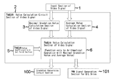
- FIG. 1 shows a block diagram of the feature value calculation circuit section 2 of the video signal.
- the feature value calculation circuit 2 of the video signal is comprised of a maximal gradation value calculation section 3 of the video signal, an average value calculation section 4 of the video signal, a feature coefficient (a, b) set point section 5 , and a video signal feature value calculation section 6 .
- An output of the input section of the video signal 1 connects to the feature value calculation circuit section 2 of video signal and the maximal gradation value calculation section 3 of video signal.
- an output of the feature value calculation section 6 of video signal is connected to a gradation conversion circuit 100 and a PWM signal generation section 101 for B/L drive.
- the maximal value (MAX value) of gradation of video signal in one frame and the average value (AVE value) of gradation of video signal in one frame are calculated at the maximal gradation value calculation section 3 of the video signal in order to calculate the feature value (hereinafter, referred to as Rank value) of video signal in one frame from the video signal inputted based on the input section of video signal 1 .
- the Rank value is calculated by a function (the following equation (a)) of only arithmetical operation at the feature value calculation section 6 of the video signal with use of a value (a, b) predetermined at feature value coefficient (a, b) set point section 5 , the MAX value, and the AVE value.
- the calculated feature value is transmitted to the gradation conversion circuit section 100 and the PWM signal generation section for B/L drive 101 .
- a configuration of the gradation conversion circuit section 100 and the PWM signal generation section for B/L drive 101 is the same as described in FIG. 8 .
- a calculation method of the MAX value will be described with reference to a flowchart in FIG. 3 .
- the video signal at first pixel is inputted, it is stored in a Register named A and a value of the A and the MAX value are compared.
- the video signal at first pixel is automatically set as the MAX value.
- a value of the register A is renewed by data of the video signal at the second pixel, and the value of the Register A and the MAX value are compared.
- the MAX value is renewed.
- the MAX value will be the same value thereof.
- a value of Register A is renewed by data of the video signal at third pixel.
- a value of Register A and the MAX value are compared each other. When a value of the Register A is more than or equal to the MAX value, the MAX value is renewed, and a value of Register A is less than MAX value, the MAX value will be the same value thereof.
- the MAX value of video signal in one frame can be calculated.
- RGB data per one pixel there are three kinds of RGB data per one pixel in the video signal.
- the largest data among them may be considered or treated as data at first pixel.
- the data of the second pixel is stored in Register B.
- the Register C is renewed by addition of the first pixel data and the second pixel data.
- the Register C is data added from the first pixel to the n-th pixel which is last pixel.
- AVE value is obtained by dividing data in the Register C by a number of n, as the number of pixels is n.
- the video signal may be considered or treated as one pixel data by adding three kinds of data. In this case, it must be required for three times of the number of pixels.
- One pixel is configured by three kinds of sub-pixels of RGB. It will be described in detail with reference to FIGS. 5A and 5B , considering the sub-pixel.
- FIG. 5A shows an average value calculation method of all sub-pixels.
- a sum of R data, G data, and B data of the inputted video signal are respectively entered in the Register B and sequentially added in the Register C, it is necessary to divide the data in the Register C by the total numbers (in this case, the total number of pixels) for calculation of the average value.
- the total number of sub-pixels of all screens is equal to 3 times of the number of pixels
- the value in the Register C may be divided by a product of a number of pixels and three.
- FIG. 5B shows an average value calculation method of maximal value in sub-pixel.
- the above method is a method taking a maximal value in three sub-pixels, entering into the Register B as a maximal value of one pixel, and sequentially adding to the Register C.
- the maximal value in the three sub-pixels is used in this case, the number of pixels is one piece per one pixel and the number for dividing is equal to the number of pixels in order to calculate an average value.
- the present invention is characterized in that the feature value of video signal is a value calculated by the above equation (a).
- PWM (Rank/ f ( n )) ⁇ 2.2 (b)
- the gamma conversion for supplement of the amount of the luminous reduction is performed after the Rank value is sent to the gradation conversion circuit section 100 .
- the video signal outputted from the gradation conversion circuit section 100 is transmitted to the display device driver in accordance with the predetermined transmission format.
- the small circuit scale can be obtained by simplification of calculation with use of a value of n-th power of two.
- the values of p and q may be, respectively, determined as appropriate values according to the resolution of the AVE value and the MAX value.
- the graph described as “linear” in FIG. 2 is a graph of the Rank value generated by the polynomial configured by only members of the MAX value and the AVE value for comparison.
- the luminance change of B/L is compared with an amount of luminance reduction calculated by the feature value generated by a linear function of the average value and maximal value in one frame of the inputted video signal, it is controlled to be always an amount of luminance reduction, which is less than or equal to an amount of the luminance reduction calculated by the linear function.
- the luminance change of B/L is illustrated as a graph in FIG. 2 , with a vertical axis to be PWM value and with a horizontal axis to be AVE value, it is controlled to be constantly curved upward (like a shape of convex) relative to a linear function shown by a first-degree polynomial function.
- Such control of a reduction of luminance is characterized by eliminating discomfort of image quality even in an image with much high gradation.
- the image seems to be dark by increasing a reduction of luminance. This is on the ground that the gradation may only be changed up to 255 when the gradation value of the inputted video signal exists near the maximal gradation value.
- An image with many of middle gradation often appears in a natural view such as shiny outdoors, plants, and fruits.
- the AVE value of the image with many of middle gradation is about 100 to 120.
- An image with many of high gradation often appears in a natural view such as an image showing and zooming white clothes, white plates and blue sky with clouds of the daytime.
- the AVE value of the image with many of high gradation is more than or equal to 180.
- the luminance reduction must be small in order not to generate a discomfort of image quality
- the gradation of many pixels can be converted.
- the image of high gradation may only be converted up to 255th gradation as well. As the total number of images including high gradation is small, it does not seem to be dark.
- the feature value of the video signal sets a value corresponding to the gradation value, which counts from the maximal gradation value of the histogram, and falls under third tens of the total numbers.
- the Image A shows 30 percentage of white window (255th gradation) in the black image (0 gradation) and the Image B shows a 29 percentage of white window (255th gradation) in the black image (0 gradation).
- the gradation in the image A which counts from a maximal gradation and falls under 30 percentage of the total number
- the gradation in the Image B which counts from the maximal gradation and falls under 30 percentage of the total number
- the Image A is an amount of luminance reduction based on 255th gradation
- the Image B is an amount of luminance reduction based on 0 gradation.
- Original images of the Image A and B become a large difference in an amount of luminance reduction in spite of little or no difference therebetween.
- FIG. 7 shows a relationship between this window size and the luminance.
- the window size is supposed to be 100 percentage.
- the window size (all white) is gradually reducing.
- the window size is supposed to be 30 percentage
- an amount of luminance reduction is zero percentage because of the luminance reduction based on the 255th gradation.
- the relationship between the inputted video signal and the luminance change of B/L will be described.
- all white is inputted as the video signal, and a pixel of black is displayed in any screen area from all white screen condition.
- the luminance of B/L is continuously reducing from the all white screen up to one pixel of white and the luminance does not change suddenly by a slight change of the video signal.
- the PWM value may exceed 100 percentage from an AVE value.
- the ill effects owing to the above may be avoided by limiting a value of the AVE, which exceeds the AVE value, by limiter (consider or treat as 100 percentage in case of exceeding 100 percentage).
- Embodiment 2 is the same configuration and operation as Embodiment 1 except the setting method of the coefficient b in this Embodiment.
- Embodiment 3 a setting method of coefficient a described in Embodiment 1 will be described.
- an image having many of low gradation that is, dark image is about 50 to 70 in AVE value. (in case of 8-bit input)
- PWM value is 30 percentage around 50 of AVE value in FIG. 11 .
- the PWM value can be increased upon determining a value of the a to be a little smaller. These can be determined considering the image quality.
- This Embodiment is the same configuration and operation as the Embodiment 1 except the setting method of coefficient a in this Embodiment.
- Embodiment 4 a circuit linking any coefficient b described in Embodiment 1 and the MAX value will be described.
- the MAX value is smaller than 255, it is possible that the luminance reduction can be prevented in the side of high gradation, as shown in FIG. 2 , by controlling the variation of the coefficient b in linkage with the MAX value.
- any coefficient c in the equation (c) is set as 216 and the coefficient (b) obtained by the equation (c) at the time of 200 in MAX value will be 12.
- Rank ( a/p ) ⁇ (1 ⁇ ( b _ m/q ) ⁇ AVE) ⁇ AVE+(1 ⁇ ( a/p ) ⁇ (1 ⁇ ( b _ m/q ) ⁇ AVE)) ⁇ MAX (d)
- the value of the coefficient (b_m) is a value used for easy understanding of the calculation in Embodiment 4. Actually, a value of b is renewed by the equation (c).
- the configuration of the present embodiment is the same as the luminance control circuit section 20 of the video signal processing circuit 15 illustrated in FIG. 8 of Embodiment 1, the feature value calculation circuit section 2 of the video signal will be described in detail.
- FIG. 14 illustrates a configuration of the feature value calculation circuit section 2 of the video signal.
- the sections which are different from Embodiment 1, are configured by appending a feature value coefficient (b_m) calculation section 7 and a feature value coefficient c set point section 8 illustrated in FIG. 14 .
- the feature value calculation circuit section 2 of the video signal is configured by a maximal gradation value calculation section 3 of the video signal, an average value calculation section 4 of the video signal, a feature value coefficient (a,b) set point section 5 , the feature value calculation section 6 of the video signal, the feature value coefficient (b_m) calculation section 7 , and the feature value coefficient c set point section 8 .
- a video signal is inputted from the feature value calculation circuit 2 of the video signal, the maximal value (MAX value) of the video signal in one frame is calculated at the maximal gradation value calculation section 3 of the video signal, and the average value (AVE value) of the video signal in one frame is calculated at the average value calculation section 4 of the video signal.
- the coefficient (b_m) can be calculated by the equation (c) in Embodiment 4, with use of the MAX value calculated at the maximal gradation value calculation section 3 of the video signal, the coefficient b predetermined at the feature value coefficient (a,b) set point section 5 , and the coefficient c predetermined at the feature value coefficient c set point section 8 .
- the Rank value can be calculated by a function used by an arithmetic operation shown by the equation (d) in Embodiment 4, with use of the coefficient a predetermined at the feature value coefficient (a,b) set point section 5 , coefficient b_m calculated by the feature value coefficient (b_m) calculation section 7 , the MAX value and the AVE value.
- the calculated feature value is transmitted to the gradation conversion circuit section 100 and the PWM signal generation section for B/L drive 101 .
- Further configurations extending from the gradation conversion circuit section 100 and the PWM signal generation section for B/L drive 101 is the same as configurations described in FIG. 8 .
- Embodiment is characterized by controlling any coefficient b described in Embodiment 1 according to the MAX value.
- the other operation is the same as one of Embodiment 1.
- the video signal is inputted to calculate the maximal gradation value (MAX) in one frame and the average value (AVE) of the video signal.
- the coefficient b is calculated by the following equation (c) based on the calculated MAX value.
- b _ m (255 /c ) ⁇ ( f ( n )/MAX) ⁇ b (c)
- the Rank value is calculated by the following equation (d) with use of the calculated MAX value and the calculated AVE value and the coefficients a and b_m.
- the equation (d) is supposed to replace the coefficient b in the equation (a) by the coefficient b_m.
- the equation for calculating the feature value may be the equation (a), as the coefficient b is renewed by the equation (c).
- Any coefficient c in the equation (c) may be set in the range of 1 to 254.
- the value c is set to make small, the value b_m may be beyond 31.
- the procedure for limiting it at a boundary value, that is, coefficient b_m beginning to go beyond 31 (31 in case of going beyond 31) and the like can be performed.
- a method for setting the value c may be designed to store in the Register IC or change the set point with use of the external ROM.
- the PWM signal for reducing the B/L luminance with use of the calculated Rank value is generated at PWM signal generation section based on the equation (b). Then, the generated PWM signal is transmitted to the B/L drive substrate 202 .
- PWM (Rank/ f ( n )) ⁇ 2.2 (b)
- the gradation conversion is performed at the gradation conversion circuit section as shown in FIG. 8 in order to perform the gamma conversion for complementing the luminance reduction.
- the video signal outputted from the gradation conversion circuit section is transmitted to the display device driver according to the predetermined transmission format.
Abstract
Description
-
Patent Literature 1 Patent Laid-open Publication No. 2008-304580 -
Patent Literature 2 Patent Laid-open Publication No. 2007-322901 -
Patent Literature 3 Patent Laid-open Publication No. 2010-204654
Rank=(a/p)×(1−(b/q)×AVE)×AVE+(1−(a/p)×(1−(b/q)×AVE))×MAX (1)
and
the backlight luminance is determined by the following equation (2) with use of PWM value,
PWM=(Rank/f(n))^2.2 (2)
-
- f(n): maximal display gradation value (255 in case of 8 bit)
b_m=(255/c)×(f(n)/MAX)×b (3)
-
- f(n): maximal display gradation value (255 incase of 8 bit)
the feature value of the video signal RANK is determined by the following equation (4) with the calculated maximal value MAX the average value AVE, the any coefficient a the calculated coefficient b_m, and the coefficients p and q,
Rank=(a/p)×(1−(b_m/q)×AVE)×AVE+(1−(a/p)×(1−(b_m/q)×AVE))×MAX (4)
and the backlight luminance is determined by the following equation (5) with a PWM value
PWM=(Rank/f(n))^2.2 (5)
- f(n): maximal display gradation value (255 incase of 8 bit)
Rank=(a/p)×(1−(b/q)×AVE)×AVE+(1−(a/p)×(1−(b/q)×AVE))×MAX (a)
-
- 1 a member multiplying a coefficient by a square of AVE value
- 2 a member multiplying a coefficient by AVE value
- 3 a member multiplying a coefficient by MAX value
- 4 a member multiplying a coefficient by a product of AVE value and MAX value
PWM=(Rank/f(n))^2.2 (b)
-
- (255 as described by 8 bit in case of the present invention)
Rank=(a/p)×AVE+(1−(a/p))×MAX (8)
Rank=(a/p)×AVE+(1−(a/p))×MAX+((a/p)×(b/q)×AVE)×(MAX−AVE) (9)
b_m=(255/c)×(f(n)/MAX)×b (c)
-
- where
- b: value of any coefficient b set at the time of 255 in MAX value
- c: any coefficient
- MAX: maximal value of gradation of video signal in one frame
- f(n): maximal display gradation value(255 in case of 8 bit)
- where
Rank=(a/p)×(1−(b_m/q)×AVE)×AVE+(1−(a/p)×(1−(b_m/q)×AVE))×MAX (d)
-
- Where
- a: any coefficient
- b_m: coefficient b obtained by the equation (c)
- p: any coefficient
- q: any coefficient
- MAX: maximal value of gradation of video signal in one frame
- AVE: average value of gradation of video signal in one frame
- Where
b_m=(255/c)×(f(n)/MAX)×b (c)
-
- where
- b: value of any coefficient b set at the time of 255 in MAX value
- c: any coefficient
- MAX: maximal value of gradation of video signal in one frame
- f(n): maximal display gradation value(255 in case of 8 bit)
- where
Rank=(a/p)×(1−(b_m/q)×AVE)×AVE+(1−(a/p)×(1−(b_m/q)×AVE))×MAX (d)
-
- where
- a: any coefficient
- b_m: coefficient obtained by the equation (c)
- p: any coefficient
- q: any coefficient
- MAX: maximal value of gradation of video signal in one frame
- AVE: average value of gradation of video signal in one frame
- where
PWM=(Rank/f(n))^2.2 (b)
-
- f(n): maximal display gradation value(255 in case of 8 bit)
- Rank: the feature value of video signal in one frame
Claims (8)
Rank=(a/p)×(1−(b/q)×AVE)×AVE+(1−(a/p)×(1−(b/q)×AVE))×MAX (1)
PWM=(Rank/f(n))^2.2 (2)
b_m=(255/c)×(f(n)/MAX)×b (3)
Rank=(a/p)×(1−(b_m/q)×AVE)×AVE+(1−(a/p)×(1−(b_m/q)×AVE))×MAX (4)
PWM=(Rank/f(n))^2.2 (5).
Applications Claiming Priority (6)
| Application Number | Priority Date | Filing Date | Title |
|---|---|---|---|
| JP2013-168804 | 2013-08-15 | ||
| JP2013168804 | 2013-08-15 | ||
| JP2014-092158 | 2014-04-26 | ||
| JP2014092158 | 2014-04-26 | ||
| JP2014159930A JP6108238B2 (en) | 2013-08-15 | 2014-08-05 | Control circuit and display device thereof |
| JP2014-159930 | 2014-08-05 |
Publications (2)
| Publication Number | Publication Date |
|---|---|
| US20150049129A1 US20150049129A1 (en) | 2015-02-19 |
| US9489899B2 true US9489899B2 (en) | 2016-11-08 |
Family
ID=52466539
Family Applications (1)
| Application Number | Title | Priority Date | Filing Date |
|---|---|---|---|
| US14/459,498 Active US9489899B2 (en) | 2013-08-15 | 2014-08-14 | Control circuit for continuous smooth reduction of backlight luminance, and a display thereof |
Country Status (3)
| Country | Link |
|---|---|
| US (1) | US9489899B2 (en) |
| JP (1) | JP6108238B2 (en) |
| CN (1) | CN104376810B (en) |
Families Citing this family (4)
| Publication number | Priority date | Publication date | Assignee | Title |
|---|---|---|---|---|
| CN105741786B (en) * | 2016-01-27 | 2018-11-02 | 努比亚技术有限公司 | Eliminate the method and mobile terminal of display screen shake |
| CN108389553B (en) * | 2018-03-27 | 2021-01-12 | 深圳创维-Rgb电子有限公司 | Backlight control method, apparatus and computer readable storage medium |
| CN111785224B (en) * | 2019-04-04 | 2022-02-08 | 海信视像科技股份有限公司 | Brightness driving method |
| CN112201202A (en) * | 2020-10-30 | 2021-01-08 | 联想(北京)有限公司 | Brightness adjusting method and device |
Citations (8)
| Publication number | Priority date | Publication date | Assignee | Title |
|---|---|---|---|---|
| WO2007046320A1 (en) | 2005-10-18 | 2007-04-26 | Sharp Kabushiki Kaisha | Liquid crystal display |
| JP2007322901A (en) | 2006-06-02 | 2007-12-13 | Sony Corp | Display device and method for driving the same |
| JP2008304580A (en) | 2007-06-06 | 2008-12-18 | Sharp Corp | Image display device |
| US20090304274A1 (en) * | 2005-12-14 | 2009-12-10 | Hideki Yoshii | Image Processing Apparatus and Image Display Apparatus |
| JP2010204654A (en) | 2009-03-03 | 2010-09-16 | Samsung Electronics Co Ltd | Light source apparatus |
| US20110050739A1 (en) * | 2009-08-31 | 2011-03-03 | Kabushiki Kaisha Toshiba | Image processor and image processing method |
| US20110109815A1 (en) * | 2009-11-12 | 2011-05-12 | Seiko Epson Corporation | Video processing circuit and method, liquid crystal display apparatus, and electronic apparatus |
| US20120026208A1 (en) * | 2010-07-30 | 2012-02-02 | Kabushiki Kaisha Toshiba | Image display apparatus |
Family Cites Families (6)
| Publication number | Priority date | Publication date | Assignee | Title |
|---|---|---|---|---|
| WO2008117393A1 (en) * | 2007-03-26 | 2008-10-02 | Mitsubishi Electric Corporation | Video display device and image display method |
| JP5340083B2 (en) * | 2009-08-28 | 2013-11-13 | キヤノン株式会社 | Image display apparatus and brightness control method thereof |
| JP5236622B2 (en) * | 2009-12-17 | 2013-07-17 | シャープ株式会社 | Display device |
| JP5662738B2 (en) * | 2010-08-23 | 2015-02-04 | ミツミ電機株式会社 | Luminance control device and luminance control method |
| JP2013092700A (en) * | 2011-10-27 | 2013-05-16 | Sharp Corp | Liquid crystal display device |
| JP5284444B2 (en) * | 2011-11-11 | 2013-09-11 | シャープ株式会社 | Video display device and television receiver |
-
2014
- 2014-08-05 JP JP2014159930A patent/JP6108238B2/en active Active
- 2014-08-13 CN CN201410398415.9A patent/CN104376810B/en active Active
- 2014-08-14 US US14/459,498 patent/US9489899B2/en active Active
Patent Citations (9)
| Publication number | Priority date | Publication date | Assignee | Title |
|---|---|---|---|---|
| WO2007046320A1 (en) | 2005-10-18 | 2007-04-26 | Sharp Kabushiki Kaisha | Liquid crystal display |
| US20080231581A1 (en) | 2005-10-18 | 2008-09-25 | Sharp Kabushiki Kaisha | Liquid Crystal Display Apparatus |
| US20090304274A1 (en) * | 2005-12-14 | 2009-12-10 | Hideki Yoshii | Image Processing Apparatus and Image Display Apparatus |
| JP2007322901A (en) | 2006-06-02 | 2007-12-13 | Sony Corp | Display device and method for driving the same |
| JP2008304580A (en) | 2007-06-06 | 2008-12-18 | Sharp Corp | Image display device |
| JP2010204654A (en) | 2009-03-03 | 2010-09-16 | Samsung Electronics Co Ltd | Light source apparatus |
| US20110050739A1 (en) * | 2009-08-31 | 2011-03-03 | Kabushiki Kaisha Toshiba | Image processor and image processing method |
| US20110109815A1 (en) * | 2009-11-12 | 2011-05-12 | Seiko Epson Corporation | Video processing circuit and method, liquid crystal display apparatus, and electronic apparatus |
| US20120026208A1 (en) * | 2010-07-30 | 2012-02-02 | Kabushiki Kaisha Toshiba | Image display apparatus |
Non-Patent Citations (1)
| Title |
|---|
| Communication dated Aug. 23, 2016, issued by the Japan Patent Office in corresponding Japanese Application No. 2014-159930. |
Also Published As
| Publication number | Publication date |
|---|---|
| CN104376810A (en) | 2015-02-25 |
| JP6108238B2 (en) | 2017-04-05 |
| US20150049129A1 (en) | 2015-02-19 |
| CN104376810B (en) | 2018-05-08 |
| JP2015215584A (en) | 2015-12-03 |
Similar Documents
| Publication | Publication Date | Title |
|---|---|---|
| US9578296B2 (en) | Signal conversion apparatus and method, and program and recording medium | |
| JP4073949B2 (en) | Display device | |
| US9711112B2 (en) | Control signal generation circuit and control signal generation method for controlling luminance in a display device | |
| US9830846B2 (en) | Image display device capable of supporting brightness enhancement and power control and method thereof | |
| JP5122927B2 (en) | Image display device and image display method | |
| JP5875423B2 (en) | Image processing apparatus and image processing method | |
| JP5258396B2 (en) | Liquid crystal display device control circuit and liquid crystal display system | |
| US20130016141A1 (en) | Method and apparatus of compensating image in a backlight local dimming system | |
| US9183797B2 (en) | Display device and control method for display device | |
| US9430977B2 (en) | Video signal processing circuit, video display device, and video signal processing method | |
| US9489899B2 (en) | Control circuit for continuous smooth reduction of backlight luminance, and a display thereof | |
| KR102510573B1 (en) | Transparent display device and method for driving the same | |
| JP2008102287A (en) | Device for controlling light source and method of controlling light source | |
| JP5314936B2 (en) | Display device and display device driving circuit | |
| JP2008026339A (en) | Display device | |
| US9311886B2 (en) | Display device including signal processing unit that converts an input signal for an input HSV color space, electronic apparatus including the display device, and drive method for the display device | |
| JP2008015123A (en) | Display device and its driving method | |
| JP5057884B2 (en) | Display device | |
| WO2012090358A1 (en) | Video signal processing device | |
| JP2009058718A (en) | Liquid crystal display | |
| JP5486791B2 (en) | Image processing device | |
| JP2018091922A (en) | Display device and display device control method | |
| KR101961231B1 (en) | Image display device and method |
Legal Events
| Date | Code | Title | Description |
|---|---|---|---|
| AS | Assignment |
Owner name: NLT TECHNOLOGIES, LTD., JAPAN Free format text: ASSIGNMENT OF ASSIGNORS INTEREST;ASSIGNOR:OOGA, KOUICHI;REEL/FRAME:034539/0829 Effective date: 20141125 |
|
| STCF | Information on status: patent grant |
Free format text: PATENTED CASE |
|
| AS | Assignment |
Owner name: TIANMA JAPAN, LTD., JAPAN Free format text: CHANGE OF NAME;ASSIGNOR:NLT TECHNOLOGIES, LTD.;REEL/FRAME:050359/0923 Effective date: 20170701 |
|
| AS | Assignment |
Owner name: TIANMA MICROELECTRONICS CO., LTD., CHINA Free format text: ASSIGNMENT OF ASSIGNORS INTEREST;ASSIGNOR:TIANMA JAPAN, LTD.;REEL/FRAME:050395/0931 Effective date: 20190910 |
|
| MAFP | Maintenance fee payment |
Free format text: PAYMENT OF MAINTENANCE FEE, 4TH YEAR, LARGE ENTITY (ORIGINAL EVENT CODE: M1551); ENTITY STATUS OF PATENT OWNER: LARGE ENTITY Year of fee payment: 4 |