US9489271B1 - User interface for restoring databases - Google Patents
User interface for restoring databases Download PDFInfo
- Publication number
- US9489271B1 US9489271B1 US13/433,709 US201213433709A US9489271B1 US 9489271 B1 US9489271 B1 US 9489271B1 US 201213433709 A US201213433709 A US 201213433709A US 9489271 B1 US9489271 B1 US 9489271B1
- Authority
- US
- United States
- Prior art keywords
- data
- selection
- restore
- backup
- abstraction
- Prior art date
- Legal status (The legal status is an assumption and is not a legal conclusion. Google has not performed a legal analysis and makes no representation as to the accuracy of the status listed.)
- Active, expires
Links
- 238000000034 method Methods 0.000 claims abstract description 70
- 238000013507 mapping Methods 0.000 claims description 2
- 238000004590 computer program Methods 0.000 claims 3
- 238000010586 diagram Methods 0.000 description 24
- 230000003287 optical effect Effects 0.000 description 7
- 238000004891 communication Methods 0.000 description 6
- 238000012545 processing Methods 0.000 description 6
- 238000012986 modification Methods 0.000 description 5
- 230000004048 modification Effects 0.000 description 5
- 239000003795 chemical substances by application Substances 0.000 description 4
- 238000011084 recovery Methods 0.000 description 3
- 230000001413 cellular effect Effects 0.000 description 2
- 238000005516 engineering process Methods 0.000 description 2
- 238000013459 approach Methods 0.000 description 1
- 230000002238 attenuated effect Effects 0.000 description 1
- 230000008859 change Effects 0.000 description 1
- 230000001186 cumulative effect Effects 0.000 description 1
- 230000003111 delayed effect Effects 0.000 description 1
- -1 e.g. Substances 0.000 description 1
- 239000000835 fiber Substances 0.000 description 1
- 229910000078 germane Inorganic materials 0.000 description 1
- 230000003993 interaction Effects 0.000 description 1
- 230000007246 mechanism Effects 0.000 description 1
- 230000002093 peripheral effect Effects 0.000 description 1
- 230000008569 process Effects 0.000 description 1
- 230000035899 viability Effects 0.000 description 1
Images


Classifications
-
- G—PHYSICS
- G06—COMPUTING; CALCULATING OR COUNTING
- G06F—ELECTRIC DIGITAL DATA PROCESSING
- G06F11/00—Error detection; Error correction; Monitoring
- G06F11/07—Responding to the occurrence of a fault, e.g. fault tolerance
- G06F11/14—Error detection or correction of the data by redundancy in operation
- G06F11/1402—Saving, restoring, recovering or retrying
- G06F11/1446—Point-in-time backing up or restoration of persistent data
- G06F11/1458—Management of the backup or restore process
- G06F11/1469—Backup restoration techniques
-
- G—PHYSICS
- G06—COMPUTING; CALCULATING OR COUNTING
- G06F—ELECTRIC DIGITAL DATA PROCESSING
- G06F11/00—Error detection; Error correction; Monitoring
-
- G—PHYSICS
- G06—COMPUTING; CALCULATING OR COUNTING
- G06F—ELECTRIC DIGITAL DATA PROCESSING
- G06F16/00—Information retrieval; Database structures therefor; File system structures therefor
- G06F16/20—Information retrieval; Database structures therefor; File system structures therefor of structured data, e.g. relational data
- G06F16/22—Indexing; Data structures therefor; Storage structures
-
- G06F17/30312—
-
- G—PHYSICS
- G06—COMPUTING; CALCULATING OR COUNTING
- G06F—ELECTRIC DIGITAL DATA PROCESSING
- G06F16/00—Information retrieval; Database structures therefor; File system structures therefor
- G06F16/20—Information retrieval; Database structures therefor; File system structures therefor of structured data, e.g. relational data
- G06F16/21—Design, administration or maintenance of databases
- G06F16/211—Schema design and management
- G06F16/213—Schema design and management with details for schema evolution support
-
- G—PHYSICS
- G06—COMPUTING; CALCULATING OR COUNTING
- G06F—ELECTRIC DIGITAL DATA PROCESSING
- G06F16/00—Information retrieval; Database structures therefor; File system structures therefor
- G06F16/20—Information retrieval; Database structures therefor; File system structures therefor of structured data, e.g. relational data
- G06F16/23—Updating
- G06F16/2365—Ensuring data consistency and integrity
-
- G06F17/30297—
-
- G06F17/30371—
-
- G—PHYSICS
- G06—COMPUTING; CALCULATING OR COUNTING
- G06F—ELECTRIC DIGITAL DATA PROCESSING
- G06F2201/00—Indexing scheme relating to error detection, to error correction, and to monitoring
- G06F2201/80—Database-specific techniques
Definitions
- This application relates to backup and restoration of databases. Particularly, this application relates to a user interface for restoring such databases.
- Data backup can be used to prevent data loss in case of any such disaster.
- a data backup process typically creates copies of original data. These copies can be used to restore the original data after a data loss event.
- the backed-up data can be stored using a variety of media, such as magnetic tape, hard drives, and/or optical storage, among others.
- Various techniques can be used to generate such backups, such full backups, incremental backups, or differential backups, among others.
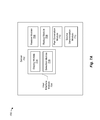
- FIG. 1 is a block diagram illustrating a distributed system, according to one embodiment.
- FIGS. 2A and 2B are flowcharts illustrating methods for restoring data in distributed systems, according to one or more embodiments.
- FIGS. 3A and 3B are flowcharts illustrating elements of methods for restoring data in distributed systems, according to one or more embodiments.
- FIG. 4 is a block diagram of a database subsystem, according to one embodiment.
- FIG. 5 is a block diagram of a virtual machine subsystem, according to one embodiment.
- FIGS. 6A and 6B are block diagrams of backup subsystems, according to some embodiments.
- FIG. 7A is a block diagram of a server, according to some embodiments.
- FIG. 7B is a block diagram illustrating operation of a server, according to some embodiments.
- FIGS. 8A and 8B illustrate example user interfaces for restoring data in distributed systems, according to some embodiments.
- FIGS. 9-12 illustrate example user interfaces for restoring data in distributed systems, according to some embodiments.
- FIG. 13 is a block diagram of various backup sets, according to some embodiments.
- FIG. 14 illustrates a restore plan, according to one embodiment.
- FIG. 15 is a block diagram illustrating various components of a server, according to one embodiment.
- FIG. 16 is a block diagram illustrating a network architecture in which embodiments of the present application can be implemented.
- FIG. 17 is a block diagram that illustrates an example of a computer system suitable for implementing embodiments of the present application.
- Modern distributed storage environments may include multiple storage objects connected via one or more interconnection networks.
- the interconnection networks provide the infrastructure to connect the various elements of a distributed shared storage environment.
- Storage systems frequently use data redundancy mechanisms to ensure data integrity, consistency, and availability.
- Other uses for data redundancy may include backing up data, distributed load sharing, disaster recovery, or point-in-time analysis and reporting.
- One approach to data redundancy is to back up data, such as database data, from a primary storage system to a second storage system. The backed-up data can be then restored, such as after a data loss event, or upon a failure of the primary storage system.
- the following description is directed to methods and systems for using a user interface for restoring databases.
- FIG. 1 is a block diagram illustrating a distributed system 100 that includes a collection of server(s), client(s), and storage.
- Distributed system 100 includes several nodes and/or subsystems, e.g., a database subsystem 102 , a virtual machine (VM) subsystem 104 , a backup subsystem 106 , one or more clients 108 ( 1 )- 108 (N), one or more servers 110 , and a network 112 .
- Each of database subsystem 102 , virtual machine subsystem 104 , backup subsystem 106 , client(s) 108 ( 1 )- 108 (N), and/or server(s) 110 can communicate with each other using a network, e.g., network 112 .
- Network 112 can include a local area network (LAN), a wide area network (WAN), a storage area network (SAN), Ethernet, and/or any combination thereof.
- LAN local area network
- WAN wide area network
- SAN storage area network
- Ethernet and/
- Database subsystem 102 can include various databases, such as SQL databases. These databases can be accessed, through network 112 , by client(s) 108 ( 1 )- 108 (N).
- Virtual machine subsystem 104 can host multiple virtual machines, each of which can include various applications. These applications can be accessed by clients 108 ( 1 )- 108 (N). The applications that execute on these virtual machines can include one or more databases, such as SQL databases.
- Backup subsystem 106 includes various backups of database subsystem 102 and/or virtual machine subsystem 104 . These various backups can be created using various backup techniques, e.g., full backups, incremental backups, differential backups, among others.
- server 110 can automatically create (e.g., by using backup subsystem 106 ) backups of database subsystem 102 and/or virtual machine subsystem 104 .
- client 108 ( 1 ) can instruct backup subsystem 106 (e.g., using server 110 ) to create backups of database subsystem 102 and/or virtual machine subsystem 104 .
- These backups can include multiple backup sets, created for the databases in 102 and/or virtual machine subsystem 104 .
- the backup sets can be created using a variety of backup methods, including streaming or block-level full backup, streaming or block-level incremental backup, differential backup, and/or log backup, among others.
- client 108 ( 1 ) accesses (e.g., over network 112 ) database subsystem 102 and/or virtual machine subsystem 104 .
- client 108 ( 1 ) can access an SQL database in database subsystem 102 and/or access various applications in virtual machine subsystem 104 .
- client 108 ( 1 ) can access server 110 to create backups of database subsystem 102 and/or virtual machine subsystem 104 (e.g., using backup subsystem 106 ).
- Client 108 ( 1 ) can access server 110 to restore one or more of the backups of database subsystem 102 and/or virtual machine subsystem 104 .
- client 108 ( 1 ) can access server 110 , using a user interface, to initiate such a restore operation.
- client 108 ( 1 ) can also access backup subsystem 106 directly to initiate the restore operation.
- Server 110 can facilitate display of a user interface that includes data abstractions of database(s) that can be recovered, as well as restore operations that can be performed on these databases.
- Server 110 can receive selections of data abstraction(s) and restore operation, and determine the backup sets that correspond to these selections, as described below.
- FIG. 2A is a flowchart illustrating a method 200 for restoring data in distributed systems, according to one or more embodiments. As will be appreciated in light of the present disclosure, this method may be modified in order to derive alternative embodiments. Also, the operations in this embodiment are shown in sequential order. However, certain operations may occur in a different order than shown, certain operations may be performed concurrently, certain operations may be combined with other operations, and certain operations may be absent in another embodiment. Method 200 is described with reference to variations of the elements described in connection with FIG. 1 . In one embodiment, method 200 can be executed on server 110 . In another embodiment, method 200 can be executed on backup subsystem 106 . In yet another embodiment, method 200 can be executed on client 108 ( 1 ).
- a first selection is received.
- server 110 can receive a selection that identifies a data abstraction.
- the data abstraction represents a data source, such as a database that can be restored.
- this selection is chosen from multiple data abstractions, where each abstraction represents a different data source.
- graphical elements for the multiple data abstractions can be displayed, e.g., in a graphical user interface (GUI).
- GUI graphical user interface
- the server can then receive a selection of one of these the data abstractions, e.g., by a selection of a corresponding graphical element from the GUI.
- a second selection is received.
- server 110 can receive a selection that identifies a restore operation.
- the restore operation is associated with the data abstraction.
- this selection is chosen from multiple restore operations, where each restore operation is associated with the data source (e.g., with a database that can be restored).
- each of these multiple restore operations is customized for the selected data abstraction, such that each restore operation can be performed for the selected data abstraction.
- restore operations that cannot be performed for the selected data abstraction are not made available as one of the choices.
- graphical elements for the multiple restore operations can be displayed, e.g., in the GUI.
- the server can then receive a selection of one of these the restore operations, e.g., by a selection of a corresponding graphical element from the GUI.
- data to be restored is determined based on the first and second selections.
- server 110 can determine what data is to be restored based on the first and second selections.
- the selections of the data abstraction and the restore operation are used to determine what data will be restored.
- the selections do not directly indicate what data will be restored.
- further details regarding how data to be restored is determined based on the first and second selections are found in Tsaur et al., U.S. patent application Ser. No. 13/314,771, filed on Dec. 8, 2011, entitled “Systems and Methods for Restoring Application Data,” which is incorporated by reference herein in its entirety and for all purposes.
- server 110 can communicate with backup subsystem 106 (e.g., to instruct backup subsystem 106 ) to restore data.
- the data to be restored can include several sets of backup data that is stored by backup subsystem 106 .
- Server 110 can communicate with backup subsystem 106 to restore these several sets of backup data.
- Sever 110 can restore these backup sets to the client requesting the backup, to database subsystem 102 and/or virtual machine subsystem 104 , and/or to another location.
- FIG. 2B is a flowchart illustrating a method 250 for restoring data in distributed systems, according to one or more embodiments. As will be appreciated in light of the present disclosure, this method may be modified in order to derive alternative embodiments. Also, the operations in this embodiment are shown in sequential order. However, certain operations may occur in a different order than shown, certain operations may be performed concurrently, certain operations may be combined with other operations, and certain operations may be absent in another embodiment.
- Method 250 is described with reference to variations of the elements described in connection with FIG. 1 . In one embodiment, method 250 can be executed on server 110 . In another embodiment, method 250 can be executed on backup subsystem 106 . In yet another embodiment, method 250 can be executed on client 108 ( 1 ). In one embodiment, method 250 is a variation of method 200 .
- a first selection is received.
- server 110 can receive a selection that identifies a data abstraction.
- the data abstraction represents a data source, such as a database that can be restored.
- this selection is chosen from multiple data abstractions, where each abstraction represents a different data source.
- graphical elements for the multiple data abstractions can be displayed, e.g., in a graphical user interface (GUI).
- GUI graphical user interface
- the server can then receive a selection of one of these data abstractions, e.g., by a selection of a corresponding graphical element from the GUI.
- element 252 is substantially similar to element 202 .
- a second selection is received.
- server 110 can receive a selection that identifies a restore operation.
- the restore operation is associated with the data abstraction.
- this selection is chosen from multiple restore operations, where each restore operation is associated with the data source (e.g., with a database that can be restored).
- each of these multiple restore operations is customized for the selected data abstraction, such that each restore operation can be performed for the selected data abstraction.
- restore operations that cannot be performed for the selected data abstraction i.e., that cannot be performed for the recoverable database
- graphical elements for the multiple restore operations can be displayed, e.g., in the GUI.
- the server can then receive a selection of one of these restore operations, e.g., by a selection of a corresponding graphical element from the GUI.
- element 254 is substantially similar to element 204 .
- a data source is determined based on the first selection.
- server 110 can determine one or more data sources that are represented by the data abstraction.
- the data abstraction is mapped to the data source.
- a selection (in element 252 ) of a data abstraction of data for a Human Resource Department is mapped to a certain database on a certain server.
- this selection (in element 252 ) of a data abstraction of data for a Human Resource Department indicates backup sets that exist for the HR Department database(s).
- the data abstraction itself does not convey such level of complexity.
- data to be restored is determined based on the data source and the second selection.
- server 110 can determine what data is to be restored based on the data source and the second selection.
- the data source and the selection of the restore operation are used to determine what data will be restored.
- the selections of elements 252 and 254 do not directly indicate what data will be restored.
- further details regarding how data to be restored is determined based on the data source and the second selection are found in Tsaur et al., U.S. patent application Ser. No. 13/314,771, filed on Dec. 8, 2011, entitled “Systems and Methods for Restoring Application Data,” which is incorporated by reference herein in its entirety and for all purposes.
- element 260 data is restored.
- server 110 can communicate with backup subsystem 106 to restore data.
- the data to be restored can include several sets of backup data that is stored by backup subsystem 106 .
- Server 110 can communicate with backup subsystem 106 to restore these several sets of backup data.
- Sever 110 can restore these backup sets to the client requesting the backup, to database subsystem 102 and/or virtual machine subsystem 104 , and/or to another location.
- element 260 is substantially similar to element 208 .
- FIG. 3A is a flowchart illustrating a detailed method 300 for restoring data in distributed systems, according to one or more embodiments. As will be appreciated in light of the present disclosure, this method may be modified in order to derive alternative embodiments. Also, the operations in this embodiment are shown in sequential order. However, certain operations may occur in a different order than shown, certain operations may be performed concurrently, certain operations may be combined with other operations, and certain operations may be absent in another embodiment.
- Method 300 is described with reference to variations of the elements described in connection with FIG. 1 . In one embodiment, method 300 can be executed on server 110 . In another embodiment, method 300 can be executed on backup subsystem 106 . In yet another embodiment, method 300 can be executed on client 108 ( 1 ). In one embodiment, method 300 is a detailed view of elements 206 and 208 of method 200 . In another embodiment, method 300 is a detailed view of elements 258 and 260 of method 250 .
- a restore plan is generated.
- the restore plan can be generated based on the first and second selections.
- the restore plan can be generated based on the data source (e.g., as determined in element 256 ) and on the second selection.
- the restore plan indicates what backup sets are needed to restore data according to the selected restore operation.
- the backup sets are selected based on first selection (i.e., identifying the data abstraction) or based on the data source.
- the restore plan can also include various restore parameters and/or indicate additional processing.
- further details regarding how to generate a restore plan based are found in Tsaur et al., U.S. patent application Ser. No. 13/314,771, filed on Dec. 8, 2011, entitled “Systems and Methods for Restoring Application Data,” which is incorporated by reference herein in its entirety and for all purposes.
- data is restored based on the restore plan.
- server 110 can communicate with backup subsystem 106 to restore data according to the restore plan.
- server 110 can communicate with backup subsystem 106 to restore each of the backup sets according to the restore parameters, as indicated by the restore plan.
- FIG. 3B is a flowchart illustrating a detailed method 350 for generating a restore plan, according to one or more embodiments.
- this method may be modified in order to derive alternative embodiments.
- the operations in this embodiment are shown in sequential order. However, certain operations may occur in a different order than shown, certain operations may be performed concurrently, certain operations may be combined with other operations, and certain operations may be absent in another embodiment.
- Method 350 is described with reference to variations of the elements described in connection with FIG. 1 .
- method 350 can be executed on server 110 .
- method 350 can be executed on backup subsystem 106 .
- method 350 can be executed on client 108 ( 1 ).
- method 350 is a detailed view of element 302 of method 300 .
- backup sets are determined.
- backup subsystem 106 can include multiple backup sets for various databases of database subsystem 102 and/or for various VMs (and/or application(s) of those VMs) of VM subsystem 104 .
- element 352 can select a subset of backup sets that includes a latest full backup set of the HR database from multiple full backup sets of this HR database, a latest differential backup set of the HR database from multiple differential backup sets of this HR database, as well as potentially multiple log backup sets.
- ordering of the backup set(s) is determined.
- the order in which the restore operation is performed may impact the result, e.g., restored data may be different depending on the order in which various backup sets are restored in the above example, the restore plan can indicate that the full backup set should be applied first, followed by the latest differential backup, and any applicable log backup sets.
- restore parameters are determined. These restore parameters can indicate various parameters to be used when restoring the data.
- the restore parameters can indicate data integrity options of each backup set, how to recreate a directory structure for the data of each backup set, whether to use and/or copy access permissions for the data of each backup set, among others.
- FIG. 4 is a block diagram 400 of a database subsystem 402 , such as database subsystem 102 of FIG. 1 .
- Database subsystem 102 can include one or more database servers 404 ( 1 )- 404 (N) and databases 406 ( 1 )- 406 (N) and 408 ( 1 )- 408 (N). Each such database server can host one or more databases, such as SQL databases.
- database server(s) 404 ( 1 )- 404 (N) can be managed by server 110 , such as over network 410 .
- Each database server 404 ( 1 )- 404 (N) can be accessed by clients 108 ( 1 )- 108 (N).
- each database 406 ( 1 )- 406 (N) can include one or more instances of a database hosted by database server 404 ( 1 ). In one embodiment, each database 406 ( 1 )- 406 (N) can be stored using a separate storage unit. In one embodiment, backup subsystem 106 can generate backup sets for databases 406 ( 1 )- 406 (N) and 408 ( 1 )- 408 (N).
- FIG. 5 is a block diagram 500 illustrating a virtual machine (VM) subsystem 502 that includes a collection of nodes and storage.
- VM subsystem 502 includes several nodes, e.g., nodes 502 A, 502 B, and 502 C.
- Each node can communicate with storage, e.g., storage 504 , using a network, e.g., network 506 .
- Each such node can implement one or more virtual machines, e.g., virtual machines 508 A- 508 D.
- each node may implement virtual machines using hypervisor technology, although other designs are contemplated.
- some nodes can also implement an agent, e.g., agents 510 A and 510 B.
- node(s) e.g., node 502 C
- node(s) include configuration information 512 for node(s) and/or VMs.
- administrator module 514 and/or agent(s) access virtual machine configuration 512 associated with VMs hosted by nodes 502 A- 502 B.
- nodes 502 A- 502 C can be managed by server 110 , such as over network 506 .
- each VM 508 A- 508 (D) can host a different application.
- Each VM 508 A- 508 D can be accessed by clients 108 ( 1 )- 108 (N), such as over network 506 .
- each application e.g., an SQL database
- each such VM 508 A- 508 D can be accessed by clients 108 ( 1 )- 108 (N), such as over network 506 .
- VMs 508 A- 508 D can store data to storage unit 504 .
- backup subsystem 106 can generate backup sets for VMs 508 A- 508 D, such as for individual applications hosted by such VMs, as well as for data stored on storage unit 504 .
- FIGS. 6A and 6B are block diagrams 500 A and 500 B of the backup subsystem, according to one embodiment. It is noted that the embodiments shown in 600 A and 600 B can be combined, e.g., the backup can be stored using storage device(s) as well as using cloud storage. In one embodiment, nodes 604 A( 1 )- 604 A(N) and nodes 604 B( 1 )- 604 B(N) can be substantially similar to each other. Both backup systems 602 A and 602 B are configured to store backups of the database subsystem and/or the VM subsystem. For example, backup systems 602 A and 602 B are configured to store backup sets of the database subsystem and/or the VM subsystem, as determined by server 110 . In one embodiment, the data abstractions represent various databases that can be restored from the backup subsystem(s) of FIGS. 6A and 6B .
- Backup subsystem 602 A includes nodes 604 A( 1 )- 604 A(N) and storage devices 606 ( 1 )- 606 (N). It is noted that although FIG. 6A shows a one-to-one correspondence between a node and a storage device, this is shown for illustrative purposes only, and other combinations are contemplated, such as each node being associated with multiple storage devices, and/or each storage device being associated with multiple nodes. Nodes 604 A( 1 )- 604 A(N) can communicate with the server, the database subsystem, and/or the VM subsystem.
- Backup subsystem 602 B includes nodes 604 B( 1 )- 604 B(N) and can connect to cloud storage 608 .
- Cloud storage 608 can be implemented using network online storage, and allow nodes 604 B to store data.
- Cloud storage 608 can be implemented using one or more servers (not shown) that give nodes 604 B( 1 )- 604 B(N) access to virtualized pools of storage to store data.
- Nodes 604 A( 1 )- 604 A(N) can communicate with the server, the database subsystem, and/or the VM subsystem.
- FIG. 7A is a block diagram 700 of a server 702 , such as server 110 , according to one embodiment.
- Server 702 includes a user interface (UI) module 704 , a restore module 706 , a backup module 708 , a plan generation module 710 , and a source determination module 712 .
- UI module 704 can include a display module 714 and a selection module 716 . It is noted that is some embodiments, one or more of these elements may be combined. For example, plan generation module 710 can be combined with source determination module 712 . It is noted that one or more of modules of server 702 may be implemented as a software and/or hardware modules. It is also noted that in some embodiments one or more of elements of server 702 may not be used.
- FIG. 7B is a block diagram 700 illustrating operation of a server when restoring data in distributed system, according to one embodiment. It is noted that is some embodiments, one or more of these elements may be combined. It is also noted that one or more of modules shown in block diagram 700 may be implemented as a software and/or hardware modules. It is also noted that in some embodiments, one or more of elements of shown in block diagram 700 may not be used. Furthermore, one or more elements and/or operations shown in block diagram 700 can be performed at a server, at a client, at a backup system, and/or a combination thereof.
- a user interface module 752 includes a display module 754 and a selection module 756 .
- user interface module 752 can be implemented on a server, such as server 110 .
- Display module 754 can communicate elements for one or more data representations 758 and one or more restore operations 760 to a display device 762 . It is noted that each restore operation 760 indicates a restore operation that is to be performed during restoration.
- Display device 762 can, upon receiving elements for data representation(s) 758 and restore operation(s) 760 , display graphical elements corresponding to data representation(s) 758 and restore operation(s) 760 . For example, display device 762 can display these graphical elements in a graphical user interface (GUI).
- GUI graphical user interface
- display module 754 can communicate additional elements to display device 762 facilitating generation of such a GUI.
- display device 762 can be implemented on a client, such as client 108 ( 1 ).
- user interface module 752 on the server can communicate elements for data representation(s) 758 and restore operation(s) 760 to display device 762 on the client.
- the server and/or client can include additional elements used for such communication.
- input module 764 can communicate one or more selections 766 ( 1 )- 766 (N) to selection module 756 (of UI module 752 ).
- input module 764 can include some type of an Input/Output (I/O) device, such as a keyboard, a mouse, a touch screen, among others, that can receive a user input selecting an element that is displayed in the GUI.
- I/O Input/Output
- each of selections 766 ( 1 )- 766 (N) can be an indication of a selection of a certain graphical element from the GUI displayed by display device 762 .
- these selections 766 include selection 766 ( 1 ) of a certain data abstraction and selection 766 ( 2 ) of a certain restore operation.
- Selection module 756 can receive selections 766 .
- Selection module 756 can communicate selections 768 (i.e., that substantially correspond to selections 766 ) to a source determination module 770 and/or a plan generation module 774 .
- source determination module 770 determines data source(s) that correspond to the data abstraction (e.g., indicated by selection 768 ). In one implementation, source determination module 770 can map the data abstraction to the data source. For example, the selected data abstraction can indicate data from a human resource (HR) department. Source determination module 770 can determine that this data abstraction corresponds to recoverable database 406 ( 1 ) that is hosted by database server 404 ( 1 ). In one embodiment, source determination module 770 can determine that the data abstraction corresponds to backed up data for this HR database. Source determination module 770 can make this determination by accessing a mapping table (that can be stored on the server). As a result, source determination module 770 can communicate indications of one or more sources 772 to plan generation module 774 . In the above example, source determination module 770 can communicate a source indication 772 indicating database 406 ( 1 ).
- HR human resource
- plan generation module 774 receives selections 768 from selection module 756 .
- Plan generation module 774 generates a restore plan based on the first selection (e.g., a data abstraction indicates in selections 768 ) and on the second selection (e.g., a restore operation indicated in selections 768 ).
- the restore plan can indicate which backup sets to use during a restoration, as well as any restore parameters used during this restoration.
- plan generation module 774 includes some or all of functionality of source determination module 770 , and thus determines data source(s) that correspond to the data abstraction (e.g., indicated by selection 768 ) during generation of the restore plan.
- plan generation module 774 receives selections 768 from selection module 756 and source indications 772 from source determination module. Plan generation module 774 generates a restore plan based on the data source(s) and on the second selection (e.g., a restore operation indicated in selections 768 ). The restore plan can indicate which backup sets to use during a restoration, as well as any restore parameters used during this restoration.
- plan generation module communicates generated restore plan 776 to restore module 778 .
- the restore plan can include indications of which backup sets to restore during restoration, as well as any restore parameters used during the restoration.
- the restore plan can also include commands used for additional processing that is to be performed before or after the backup sets are restored.
- plan generation module 774 and/or source determination module 770 are found in Tsaur et al., U.S. patent application Ser. No. 13/314,771, filed on Dec. 8, 2011, entitled “Systems and Methods for Restoring Application Data,” which is incorporated by reference herein in its entirety and for all purposes.
- Restore module 778 receives restore plan 776 from plan generation module 774 . Restore module performs the restoration as indicated by restore plan 776 .
- restore module 778 is implemented on the server, and thus communicates with the backup subsystem to perform the restoration.
- restore module 778 can be implemented on the backup subsystem.
- Restore module 778 can restore data from the backup sets as restored data 780 .
- Restored data 780 can be stored in the original source of the data, e.g., in the source represented by the data abstraction, and/or at another location, e.g., as indicated in the restore plan.
- UI module 752 , source determination module 770 , plan generation module 774 , and restore module are implemented on a server, whereas display device 762 and input module 764 are implemented on a client.
- the server and/or client can include additional elements used for communication of data abstraction(s), restore operation(s) and/or selections (elements 766 ).
- all of these modules can be implemented on the client.
- all of these modules can be implemented on the server.
- FIGS. 8A and 8B illustrate example graphical user interfaces (e.g., GUIs) for restoring data in distributed systems, according to some embodiments.
- FIG. 8A illustrates an example GUI 800 that can be displayed using a display device, such as display device 762 .
- GUI 800 can is shown on a display 802 .
- GUI 800 can display graphical elements 804 for data abstractions and graphical elements 806 for restore operations.
- graphical elements 804 can correspond to data abstractions that represent databases that can be restored.
- graphical elements 804 display a logical view of the databases that can be restored, i.e., instead of displaying multiple backup sets.
- GUI 800 can also display a selection 808 of one of the graphical elements 804 for data abstractions.
- GUI 800 can also display a selection 810 of one of graphical elements 806 for the restore operations.
- FIG. 8B illustrates another example GUI 850 that can be displayed using a display device, such as display device 762 .
- GUI 850 can is shown on a display 852 .
- GUI 850 can display icons 854 for data abstractions and icons 856 for restore operations.
- icons 854 can correspond to data abstractions that represent databases that can be restored.
- icons 854 display a logical view of the databases that can be restored, i.e., instead of displaying multiple backup sets.
- GUI 850 can also display a selection 858 of one of icons 854 for data abstractions.
- GUI 850 can also display a selection 860 of one of icons 856 for restore operations.
- GUI 850 can optionally display a window 862 ( 1 ), where icons 854 for data abstractions are displayed.
- GUI 850 can optionally display a window 862 ( 2 ), where icons 856 for restore operations are displayed.
- FIGS. 9-12 illustrate example user interfaces for restoring data in distributed systems, according to some embodiments.
- FIGS. 9-12 illustrate operation of a wizard that can guide a user (e.g., user of client 108 ( 1 )) through a series of displays, thus providing an easy-to-use interface for restoring databases.
- a user e.g., user of client 108 ( 1 )
- FIGS. 9-12 can be used during operation of such a GUI.
- FIG. 9 illustrates a GUI 900 that is shown on display 902 .
- GUI 900 includes a first display area 904 and a second display area 906 .
- First display area 904 shows various icons that can indicate various operations, including backup operations, search operations, and a restore operation.
- Selection 908 can select one of these icons, e.g., for a certain restore operation.
- Second display area 906 shows various icons that can indicate various data abstractions.
- Selection 910 can select one of these icons, e.g., for a certain data abstraction.
- display area 906 can also display general status information for various servers (such as servers of FIG. 4 ), that can be represented by the data abstractions.
- one or both selections 908 and 910 can be selected by a user, such as by using a keyboard, a mouse, a touch screen and/or another I/O device.
- FIG. 10 illustrates a GUI 1000 that is shown on display 1002 , according to one embodiment.
- GUI 1000 includes a display area 1004 .
- Display area 1004 shows various icons that can indicate various data abstractions.
- Selection 1006 can select one of these icons, e.g., corresponding to a certain data abstraction.
- selection 1006 can be selected by a user, such as by using a keyboard, a mouse, a touch screen and/or another I/O device.
- icons shown in area 1004 represent a type of recovery (i.e., restoration) that is to be performed, such as on the data abstractions chosen in element 910 .
- selection 1006 can indicate that the recovery will restore SQL database(s).
- FIG. 11 illustrates a GUI 1100 that is shown on display 1102 , according to one embodiment.
- GUI 1100 includes a first display area 1104 and a second display area 1108 .
- First display area 1104 shows various icons that can indicate a first level of data abstraction, such as various resources. These resources can represent a certain database server as well as instances of this database server, which can be graphically presented in a hierarchical tree format.
- Selection 1106 can select one of these data abstractions, e.g., a first instance (SQLEXPRESS) of an SQL server (WIN2K8R2E-SQL).
- SQL server WIN2K8R2E-SQL
- Second display area 1108 shows various icons that can indicate a second level of data abstractions.
- second display area 1108 shows icons for second level of data abstractions that correspond to selection 1106 .
- Selection 1110 can select one of these icons, e.g., corresponding to a certain data abstraction.
- the icons for second level of abstraction 1108 can indicate names of databases, e.g., databases of the SQL database selected using selection 1106 .
- second display area 1108 is populated with icons that correspond to the selected icon in selection 1106 .
- icons shown in area 1108 represent databases 406 ( 1 )- 406 (N).
- one or both selections 908 and 910 can be selected by a user, such as by using a keyboard, a mouse, a touch screen and/or another I/O device.
- FIGS. 9-11 illustrate a first selection of methods 200 and 250 . It is noted that in some embodiments, not all of FIGS. 9-11 are used.
- the first selection that identifies the data abstraction can include selection 1006 of FIG. 10 .
- FIG. 12 illustrates a GUI 1200 that is shown on display 1202 , according to one embodiment.
- GUI 1200 includes a display area 1204 .
- Display area 1204 shows various icons that can indicate various restore operations.
- Selection 1206 can select one of these icons, e.g., corresponding to a certain restore operation.
- selection 1206 can be selected by a user, such as by using a keyboard, a mouse, a touch screen and/or another I/O device.
- selection 1206 can select a restoration operation for restoration of data to a point in time in the transaction log up to and including a specified time.
- GUI 1200 can also provide for additional selections, such as for indicating the specified time for the selected restore operation.
- the restore options can include 1) restoring data to the latest available backup set, 2) restoring data to a backup set time that is selected, 3) restoring data to a point in time in a transaction log, such as up to and including a specified time, 4) restoring data to a named transaction within the transaction log, or 5) to an individual backup set that is selected for available backup sets, e.g., such as for a user-selected database.
- the fifth option can use sources 772 as determined from the user selections.
- GUI 1200 can allow a selection of individual backup sets, restore parameters, and/or additional processing.
- one of the options e.g., perform a restoration to the latest available backup set associated with the selected data abstraction
- FIG. 13 is a block diagram 1300 illustrating various backup sets, according to some embodiments.
- the backup subsystem can generate backup sets (i.e., when performing backups) using a variety of backup techniques.
- the backup operations can be determined by the server, client(s), and/or the backup subsystem.
- backup techniques can be selected using the GUI of FIG. 9 .
- databases 404 ( 1 )- 404 (N) can be backed up, using multiple techniques, to generate multiple backup sets.
- the backups of FIG. 13 can also include backups of the VM subsystem, including backups of the databases(s) of these VMs.
- a backup set corresponds to a backup that was made at a particular point in time.
- Backups can include full backup 1302 , differential backup 1306 , log backup 1310 , and/or other backups 1312 .
- Full backup 1302 can include backup sets 1304 ( 1 )- 1304 (N).
- Differential backup 1306 can include backup sets 1308 ( 1 )- 1308 (N), where each backup set can be a cumulative differential backup.
- Log backup 1310 can include backup sets 1312 ( 1 )- 1312 (N), where each backup set can be a transaction log.
- other backup 1312 can include backups 1318 ( 1 )- 1318 (N).
- an SQL database can be backed-up using a full backup every one hr, using a differential backup every 20 minutes, and using a log backup every 5 minutes. Each one of these backup operations can generate various backup sets (that are stored by the backup subsystem).
- FIG. 14 is a diagram 1400 illustrating a restore plan 1402 , according to one embodiment.
- Restore plan 1402 can be generated by the plan generation module and be used, such as by the restore module, to perform a restoration of data. As described above, restore plan 1402 is generated based on received selections (and in some embodiments, including data source indications). Restore plan 1402 is used to generate restored data.
- Restore plan includes selections of various backup sets 1404 ( 1 )- 1404 (N).
- Restore plan can also include restore parameters 1406 .
- Restore plan 1402 can also indicate an order (e.g., restore order 1410 ) in which the backup sets are to be restored.
- Restore plan 1402 can also include additional processing 1408 , which can be instructions (i.e., to be used by the restore module) after and/or before the backup sets are restored in the specified order.
- restore plan 1402 should indicate that the latest full backup set for this HR database is selected first, followed by the latest differential backup set for this HR database, and lastly by the log backup sets (i.e., subsequent to the latest differential backup set) for this HR database.
- restore plan 1402 in order to restore a certain marketing database to a certain point in time (e.g., the second restore operation of FIG.
- restore plan 1402 should indicate that the full backup set prior to this certain time for this marketing database is selected first, followed by a certain differential backup set for this marketing database (also prior to the selected time), and by the log backup sets subsequent to the certain differential backup set (i.e., up to and including the log backup set containing data prior to the selected time).
- restore plan 1402 in order to restore a certain engineering database to a point in time in a transaction log, up to and including a certain time (e.g., the third restore operation of FIG. 12 ), restore plan 1402 should indicate that the full backup set prior to this certain time for this engineering database is selected first, followed by a certain differential backup set for this engineering database (also prior to the selected time), and by the log backup sets subsequent to the certain differential backup set (i.e., up to and including the log backup set containing data prior to the selected time).
- restore plan 1402 should indicate that the full backup set prior to a time that this transaction took place for this sales database is selected first, followed by a certain differential backup set for this sales database (also prior to the time of this transaction), and by the log backup sets subsequent to the certain differential backup set (i.e., up to and including the log backup set containing data prior to the selected transaction).
- the plan generation module generates restore plan 1402 that can be used to restore the backup sets in the proper order to perform the restore operation as specified by the GUI selections.
- the GUI selections do not specify the backup sets, restore order, restore parameters, or the additional processing. Instead, the backup sets, restore order, restore parameters, or the additional processing are determined by the plan generation module and/or the source determination module.
- FIG. 15 is a block diagram 1500 of a server 1502 , such as server 1110 and/or 702 .
- Server 1502 includes a processor 1504 , communication subsystem 1506 , and a memory 1508 .
- Memory 1508 includes a display module 1510 , a selection module 1512 , a plan generation module 1514 , a restore module 1516 , a backup module 1518 , a file system 1520 , and a source determination module 1522 . It is noted that is some embodiments, one or more of these elements may be combined. For example, source determination module and plan generation module may be combined into one module. It is also noted that one or more of modules 1510 - 1522 may be implemented as a software and/or hardware module.
- Processor(s) 1504 can execute one or more of modules 1510 - 1522 .
- One or more of modules 1510 - 1522 can implement at least portions of methods 200 , 250 , 300 , and/or 350 .
- modules 1510 - 1522 can operate as described with reference to FIG. 7B .
- FIG. 16 is a simplified block diagram illustrating a network architecture 1600 in which one or more clients are provided with access to a server via various network connections.
- clients 1602 ( 1 )-(N) are coupled to a network 1610 , and so are able to access a server 1606 (which can be used to implement server(s) and node(s) of FIGS. 1, 4, 5, 6A, 6B , and/or 7 A) via network 1610 .
- Other servers can be used instead to implement server(s) and node(s) of FIGS.
- a client can be implemented using, for example, a desktop computer, a laptop computer, a workstation, a server, a cell phone, a smart phone, a network-enabled personal digital assistant (PDA), or the like.
- An example of network 1610 which can be used by clients 1602 ( 1 )-(N) to access server 1606 , is the Internet.
- access to server 1606 can be provided by a local area network (LAN) utilizing Ethernet, IEEE 802.11x, or some other communications protocol.
- LAN local area network
- server 1606 can be accessed by clients coupled directly thereto (not shown).
- server 1606 is coupled to a server storage device 1608 , which includes a data volume such as storage 116 and/or storage 404 , among others.
- Server storage device 1608 can be implemented as a single storage device or a collection of storage devices.
- Server storage device 1608 can also be implemented as a storage area network, which couples remote storage devices to a server (e.g., server 1606 ), such that the remote storage devices appear as locally-attached storage devices to the server's OS, for example.
- server storage device 1608 can be implemented by any type of computer-readable storage medium, including, but not limited to, internal or external hard disk drives (HDD), optical drives (e.g., CD-R, CD-RW, DVD-R, DVD-RW, and the like), flash memory drives (e.g., USB memory sticks and the like), tape drives and the like.
- HDD hard disk drives
- optical drives e.g., CD-R, CD-RW, DVD-R, DVD-RW, and the like
- flash memory drives e.g., USB memory sticks and the like
- tape drives e.g., USB disk drives, and the like
- network architecture 1600 can include other components such as routers, firewalls and the like that are not germane to the discussion of the present network and will not be discussed further herein.
- network architecture 1600 can include other components such as routers, firewalls and the like that are not germane to the discussion of the present network and will not be discussed further herein.
- other configurations are possible.
- clients 1602 ( 1 )-(N) can be directly coupled to server storage device 1608 without the user of a server or Internet; server 1606 can be used to implement both the clients and the server; network architecture 1600 can be implemented without the use of clients 1602 ( 1 )-(N); and so on.
- server 1606 services requests to data generated by clients 1602 ( 1 )-(N) to data stored in server storage device 1608 .
- Any of the functionality of the nodes, agents, and/or administration modules can be implemented using one of the server(s) and node(s) of FIGS. 1, 4, 5, 6A, 6B , and/or 7 A.
- FIG. 17 depicts a block diagram of a computer system 1710 suitable for implementing the present disclosure.
- Computer system 1710 may be illustrative of various computer systems in the networked system of FIG. 1 , such as node(s) and/or coordinator node(s), among others.
- Computer system 1710 includes a bus 1712 which interconnects major subsystems of computer system 1710 , such as a central processor 1714 , a system memory 1717 (typically RAM, but which may also include ROM, flash RAM, or the like), an input/output controller 1718 , an external audio device, such as a speaker system 1720 via an audio output interface 1722 , an external device, such as a display screen 1724 via display adapter 1726 , serial ports 1728 and 1730 , a keyboard 1732 (interfaced with a keyboard controller 1733 ), a storage interface 1734 , a floppy disk drive 1737 operative to receive a floppy disk 1738 , a host bus adapter (HBA) interface card 1735 A operative to connect with a Fibre Channel network 1790 , a host bus adapter (HBA) interface card 1735 B operative to connect to a SCSI bus 1739 , and an optical disk drive 1740 operative to receive an optical disk 1742 .
- HBA host bus
- mouse 1746 or other point-and-click device, coupled to bus 1712 via serial port 1728
- modem 1747 coupled to bus 1712 via serial port 1730
- network interface 1748 coupled directly to bus 1712 .
- Bus 1712 allows data communication between central processor 1714 and system memory 1717 , which may include read-only memory (ROM) or flash memory (neither shown), and random access memory (RAM) (not shown), as previously noted.
- the RAM is generally the main memory into which the operating system and application programs are loaded.
- the ROM or flash memory can contain, among other code, the Basic Input-Output system (BIOS) which controls basic hardware operation such as the interaction with peripheral components.
- BIOS Basic Input-Output system
- Applications resident with computer system 1710 are generally stored on and accessed via a computer readable medium, such as a hard disk drive (e.g., fixed disk 1744 ), an optical drive (e.g., optical drive 1740 ), a floppy disk unit 1737 , or other storage medium. Additionally, applications can be in the form of electronic signals modulated in accordance with the application and data communication technology when accessed via network modem 1747 or interface 1748 .
- Storage interface 1734 can connect to a standard computer readable medium for storage and/or retrieval of information, such as a fixed disk drive 1744 .
- Fixed disk drive 1744 may be a part of computer system 1710 or may be separate and accessed through other interface systems.
- Modem 1747 may provide a direct connection to a remote server via a telephone link or to the Internet via an internet service provider (ISP).
- ISP internet service provider
- Network interface 1748 may provide a direct connection to a remote server via a direct network link to the Internet via a POP (point of presence).
- Network interface 1748 may provide such connection using wireless techniques, including digital cellular telephone connection, Cellular Digital Packet Data (CDPD) connection, digital satellite data connection or the like.
- CDPD Cellular Digital Packet Data
- FIG. 17 Many other devices or subsystems (not shown) may be connected in a similar manner (e.g., document scanners, digital cameras and so on). Conversely, all of the devices shown in FIG. 17 need not be present to practice the present disclosure.
- the devices and subsystems can be interconnected in different ways from that shown in FIG. 17 .
- the operation of a computer system such as that shown in FIG. 17 is readily known in the art and is not discussed in detail in this application. Code for using server(s) for restoring data (such as described above with reference to the methods of FIGS.
- 2A, 2B, 3A , and/or 3 B), etc., to implement the present disclosure can be stored in computer-readable storage media such as one or more of system memory 1717 , fixed disk 1744 , optical disk 1742 , or floppy disk 1738 .
- Memory 1720 is also used for storing temporary variables or other intermediate information during the execution of instructions by the processor 1710 .
- the operating system provided on computer system 1710 may be MS-DOS®, MS-WINDOWS®, OS/2®, UNIX®, Linux®, or another known operating system.
- a signal can be directly transmitted from a first block to a second block, or a signal can be modified (e.g., amplified, attenuated, delayed, latched, buffered, inverted, filtered, or otherwise modified) between the blocks.
- a signal can be directly transmitted from a first block to a second block, or a signal can be modified (e.g., amplified, attenuated, delayed, latched, buffered, inverted, filtered, or otherwise modified) between the blocks.
- modified signals e.g., amplified, attenuated, delayed, latched, buffered, inverted, filtered, or otherwise modified
- a signal input at a second block can be conceptualized as a second signal derived from a first signal output from a first block due to physical limitations of the circuitry involved (e.g., there will inevitably be some attenuation and delay). Therefore, as used herein, a second signal derived from a first signal includes the first signal or any modifications to the first signal, whether due to circuit limitations or due to passage through other circuit elements which do not change the informational and/or final functional aspect of the first signal.
Abstract
Description
Claims (20)
Priority Applications (1)
| Application Number | Priority Date | Filing Date | Title |
|---|---|---|---|
| US13/433,709 US9489271B1 (en) | 2012-03-29 | 2012-03-29 | User interface for restoring databases |
Applications Claiming Priority (1)
| Application Number | Priority Date | Filing Date | Title |
|---|---|---|---|
| US13/433,709 US9489271B1 (en) | 2012-03-29 | 2012-03-29 | User interface for restoring databases |
Publications (1)
| Publication Number | Publication Date |
|---|---|
| US9489271B1 true US9489271B1 (en) | 2016-11-08 |
Family
ID=57210854
Family Applications (1)
| Application Number | Title | Priority Date | Filing Date |
|---|---|---|---|
| US13/433,709 Active 2032-05-27 US9489271B1 (en) | 2012-03-29 | 2012-03-29 | User interface for restoring databases |
Country Status (1)
| Country | Link |
|---|---|
| US (1) | US9489271B1 (en) |
Cited By (2)
| Publication number | Priority date | Publication date | Assignee | Title |
|---|---|---|---|---|
| US20160254966A1 (en) * | 2013-10-31 | 2016-09-01 | Hewlett Packard Enterprise Development Lp | Network database hosting |
| US20180341673A1 (en) * | 2017-05-25 | 2018-11-29 | Collective, Inc. | Systems and Methods for Providing Real-Time Discrepancies Between Disparate Execution Platforms |
Citations (29)
| Publication number | Priority date | Publication date | Assignee | Title |
|---|---|---|---|---|
| US5220657A (en) * | 1987-12-02 | 1993-06-15 | Xerox Corporation | Updating local copy of shared data in a collaborative system |
| US5642505A (en) * | 1993-03-04 | 1997-06-24 | Mitsubishi Denki Kabushiki Kaisha | Backup, restoration, migration systems of a database |
| US20030046313A1 (en) * | 2001-08-31 | 2003-03-06 | Arkivio, Inc. | Techniques for restoring data based on contents and attributes of the data |
| US6628660B1 (en) * | 1999-06-11 | 2003-09-30 | Lattice Semiconductor Corporation | Finite state machine with associated memory |
| US6687878B1 (en) * | 1999-03-15 | 2004-02-03 | Real Time Image Ltd. | Synchronizing/updating local client notes with annotations previously made by other clients in a notes database |
| US20040205050A1 (en) * | 2003-04-10 | 2004-10-14 | International Business Machines Corporation | Application of queries against incomplete schemas |
| US6877137B1 (en) * | 1998-04-09 | 2005-04-05 | Rose Blush Software Llc | System, method and computer program product for mediating notes and note sub-notes linked or otherwise associated with stored or networked web pages |
| US6885999B1 (en) * | 2000-05-10 | 2005-04-26 | Cisco Technology, Inc. | Digital identifiers and digital identifier control systems for intellectual properties |
| US20060206544A1 (en) * | 2005-03-09 | 2006-09-14 | Microsoft Corporation | Automatic backup and restore system and method |
| US20070266394A1 (en) * | 2004-02-12 | 2007-11-15 | Odent Stephane V | Device and a Method for Processing Events and Actions |
| US20080250072A1 (en) * | 2007-04-03 | 2008-10-09 | International Business Machines Corporation | Restoring a source file referenced by multiple file names to a restore file |
| US7437388B1 (en) * | 2004-12-21 | 2008-10-14 | Symantec Corporation | Protecting data for distributed applications using cooperative backup agents |
| US20090307333A1 (en) * | 2008-06-05 | 2009-12-10 | Palm, Inc. | Restoring of data to mobile computing device |
| US7827159B2 (en) * | 2004-06-25 | 2010-11-02 | International Business Machines Corporation | Automated data model extension through data crawler approach |
| US20100293147A1 (en) * | 2009-05-12 | 2010-11-18 | Harvey Snow | System and method for providing automated electronic information backup, storage and recovery |
| US20110016089A1 (en) * | 2009-07-16 | 2011-01-20 | Apple Inc. | Restoring data to a mobile device |
| US8042172B1 (en) * | 2006-02-02 | 2011-10-18 | Emc Corporation | Remote access architecture enabling a client to perform an operation |
| US8099392B2 (en) * | 2007-06-08 | 2012-01-17 | Apple Inc. | Electronic backup of applications |
| US20120117033A1 (en) * | 2010-11-04 | 2012-05-10 | Bbs Technologies, Inc. | Method and apparatus for performing a near-instantaneous restore of a database |
| US8200633B2 (en) * | 2009-08-07 | 2012-06-12 | International Business Machines Corporation | Database backup and restore with integrated index reorganization |
| US20120151272A1 (en) * | 2010-12-09 | 2012-06-14 | International Business Machines Corporation | Adding scalability and fault tolerance to generic finite state machine frameworks for use in automated incident management of cloud computing infrastructures |
| US20120150806A1 (en) * | 2010-12-09 | 2012-06-14 | International Business Machines Corporation | Normalizing data on database restore |
| US20120310896A1 (en) * | 2011-06-03 | 2012-12-06 | Apple Inc. | Methods and apparatus for multi-phase restore |
| US20120311280A1 (en) * | 2011-06-03 | 2012-12-06 | Apple Inc. | Methods and apparatus for multi-source restore |
| US20120310889A1 (en) * | 2011-06-03 | 2012-12-06 | Apple Inc. | Methods and apparatus for multi-phase multi-source backup |
| US8341127B1 (en) * | 2006-02-02 | 2012-12-25 | Emc Corporation | Client initiated restore |
| US8364640B1 (en) * | 2010-04-09 | 2013-01-29 | Symantec Corporation | System and method for restore of backup data |
| US8566361B2 (en) * | 2009-10-21 | 2013-10-22 | Delphix Corp. | Datacenter workflow automation scenarios using virtual databases |
| US8819471B2 (en) * | 2011-06-03 | 2014-08-26 | Apple Inc. | Methods and apparatus for power state based backup |
-
2012
- 2012-03-29 US US13/433,709 patent/US9489271B1/en active Active
Patent Citations (34)
| Publication number | Priority date | Publication date | Assignee | Title |
|---|---|---|---|---|
| US5220657A (en) * | 1987-12-02 | 1993-06-15 | Xerox Corporation | Updating local copy of shared data in a collaborative system |
| US5642505A (en) * | 1993-03-04 | 1997-06-24 | Mitsubishi Denki Kabushiki Kaisha | Backup, restoration, migration systems of a database |
| US6877137B1 (en) * | 1998-04-09 | 2005-04-05 | Rose Blush Software Llc | System, method and computer program product for mediating notes and note sub-notes linked or otherwise associated with stored or networked web pages |
| US6687878B1 (en) * | 1999-03-15 | 2004-02-03 | Real Time Image Ltd. | Synchronizing/updating local client notes with annotations previously made by other clients in a notes database |
| US6628660B1 (en) * | 1999-06-11 | 2003-09-30 | Lattice Semiconductor Corporation | Finite state machine with associated memory |
| US6885999B1 (en) * | 2000-05-10 | 2005-04-26 | Cisco Technology, Inc. | Digital identifiers and digital identifier control systems for intellectual properties |
| US20030046313A1 (en) * | 2001-08-31 | 2003-03-06 | Arkivio, Inc. | Techniques for restoring data based on contents and attributes of the data |
| US20040205050A1 (en) * | 2003-04-10 | 2004-10-14 | International Business Machines Corporation | Application of queries against incomplete schemas |
| US20070266394A1 (en) * | 2004-02-12 | 2007-11-15 | Odent Stephane V | Device and a Method for Processing Events and Actions |
| US7827159B2 (en) * | 2004-06-25 | 2010-11-02 | International Business Machines Corporation | Automated data model extension through data crawler approach |
| US8224872B2 (en) * | 2004-06-25 | 2012-07-17 | International Business Machines Corporation | Automated data model extension through data crawler approach |
| US7437388B1 (en) * | 2004-12-21 | 2008-10-14 | Symantec Corporation | Protecting data for distributed applications using cooperative backup agents |
| US20060206544A1 (en) * | 2005-03-09 | 2006-09-14 | Microsoft Corporation | Automatic backup and restore system and method |
| US8042172B1 (en) * | 2006-02-02 | 2011-10-18 | Emc Corporation | Remote access architecture enabling a client to perform an operation |
| US8341127B1 (en) * | 2006-02-02 | 2012-12-25 | Emc Corporation | Client initiated restore |
| US8800023B2 (en) * | 2006-02-02 | 2014-08-05 | Emc Corporation | Remote access architecture enabling a client to perform an operation |
| US20080250072A1 (en) * | 2007-04-03 | 2008-10-09 | International Business Machines Corporation | Restoring a source file referenced by multiple file names to a restore file |
| US8099392B2 (en) * | 2007-06-08 | 2012-01-17 | Apple Inc. | Electronic backup of applications |
| US20090307333A1 (en) * | 2008-06-05 | 2009-12-10 | Palm, Inc. | Restoring of data to mobile computing device |
| US20100293147A1 (en) * | 2009-05-12 | 2010-11-18 | Harvey Snow | System and method for providing automated electronic information backup, storage and recovery |
| US20110016089A1 (en) * | 2009-07-16 | 2011-01-20 | Apple Inc. | Restoring data to a mobile device |
| US8200633B2 (en) * | 2009-08-07 | 2012-06-12 | International Business Machines Corporation | Database backup and restore with integrated index reorganization |
| US8566361B2 (en) * | 2009-10-21 | 2013-10-22 | Delphix Corp. | Datacenter workflow automation scenarios using virtual databases |
| US8364640B1 (en) * | 2010-04-09 | 2013-01-29 | Symantec Corporation | System and method for restore of backup data |
| US20120117033A1 (en) * | 2010-11-04 | 2012-05-10 | Bbs Technologies, Inc. | Method and apparatus for performing a near-instantaneous restore of a database |
| US8543549B2 (en) * | 2010-12-09 | 2013-09-24 | International Business Machines Corporation | Normalizing data on database restore |
| US20120150806A1 (en) * | 2010-12-09 | 2012-06-14 | International Business Machines Corporation | Normalizing data on database restore |
| US20120151272A1 (en) * | 2010-12-09 | 2012-06-14 | International Business Machines Corporation | Adding scalability and fault tolerance to generic finite state machine frameworks for use in automated incident management of cloud computing infrastructures |
| US20120310894A1 (en) * | 2011-06-03 | 2012-12-06 | Apple Inc. | Methods and apparatus for interface in multi-phase restore |
| US20120310889A1 (en) * | 2011-06-03 | 2012-12-06 | Apple Inc. | Methods and apparatus for multi-phase multi-source backup |
| US20120311280A1 (en) * | 2011-06-03 | 2012-12-06 | Apple Inc. | Methods and apparatus for multi-source restore |
| US20120310896A1 (en) * | 2011-06-03 | 2012-12-06 | Apple Inc. | Methods and apparatus for multi-phase restore |
| US8819471B2 (en) * | 2011-06-03 | 2014-08-26 | Apple Inc. | Methods and apparatus for power state based backup |
| US8868859B2 (en) * | 2011-06-03 | 2014-10-21 | Apple Inc. | Methods and apparatus for multi-source restore |
Non-Patent Citations (1)
| Title |
|---|
| Active Directory backup and restore with Acronis Backup & Recovery 11, Technical white paper, Copyright © Acronis, Inc., 2000-2011. * |
Cited By (4)
| Publication number | Priority date | Publication date | Assignee | Title |
|---|---|---|---|---|
| US20160254966A1 (en) * | 2013-10-31 | 2016-09-01 | Hewlett Packard Enterprise Development Lp | Network database hosting |
| US10367702B2 (en) * | 2013-10-31 | 2019-07-30 | Hewlett Packard Enterprise Development Lp | Network database hosting |
| US20180341673A1 (en) * | 2017-05-25 | 2018-11-29 | Collective, Inc. | Systems and Methods for Providing Real-Time Discrepancies Between Disparate Execution Platforms |
| US11599521B2 (en) * | 2017-05-25 | 2023-03-07 | Zeta Global Corp. | Systems and methods for providing real-time discrepancies between disparate execution platforms |
Similar Documents
| Publication | Publication Date | Title |
|---|---|---|
| US10055300B2 (en) | Disk group based backup | |
| US10073747B2 (en) | Reducing recovery time in disaster recovery/replication setup with multitier backend storage | |
| US11829263B2 (en) | In-place cloud instance restore | |
| US10169173B2 (en) | Preserving management services with distributed metadata through the disaster recovery life cycle | |
| US9703647B2 (en) | Automated policy management in a virtual machine environment | |
| US11016935B2 (en) | Centralized multi-cloud workload protection with platform agnostic centralized file browse and file retrieval time machine | |
| US9514004B2 (en) | Restore in cascaded copy environment | |
| US9075771B1 (en) | Techniques for managing disaster recovery sites | |
| US8539087B2 (en) | System and method to define, visualize and manage a composite service group in a high-availability disaster recovery environment | |
| US9275060B1 (en) | Method and system for using high availability attributes to define data protection plans | |
| US10061665B2 (en) | Preserving management services with self-contained metadata through the disaster recovery life cycle | |
| US11003362B2 (en) | Disaster recovery practice mode for application virtualization infrastructure | |
| US11836513B2 (en) | Transitioning volumes between storage virtual machines | |
| US20220114059A1 (en) | Automated backup and restore of a disk group | |
| US20190227888A1 (en) | Handling node failure in multi-node data storage systems | |
| US9489271B1 (en) | User interface for restoring databases | |
| US10365950B2 (en) | Resource throttling and automated policy management in a virtual machine environment | |
| US11656947B2 (en) | Data set recovery from a point-in-time logical corruption protection copy | |
| US20170351440A1 (en) | Data loss recovery in a secondary storage controller from a primary storage controller | |
| US8738581B1 (en) | Using multiple clients for data backup | |
| US10628075B1 (en) | Data protection compliance between storage and backup policies of virtual machines | |
| WO2023121874A1 (en) | Backup, restore, and migration of cloud managed configuration properties |
Legal Events
| Date | Code | Title | Description |
|---|---|---|---|
| AS | Assignment |
Owner name: SYMANTEC CORPORATION, CALIFORNIA Free format text: ASSIGNMENT OF ASSIGNORS INTEREST;ASSIGNORS:TSAUR, YNN-PYNG "ANKER";ABRAHAM, LIJO J.;PAYNE, MICHAEL A.;AND OTHERS;REEL/FRAME:027954/0588 Effective date: 20120315 |
|
| AS | Assignment |
Owner name: VERITAS US IP HOLDINGS LLC, CALIFORNIA Free format text: ASSIGNMENT OF ASSIGNORS INTEREST;ASSIGNOR:SYMANTEC CORPORATION;REEL/FRAME:037693/0158 Effective date: 20160129 |
|
| AS | Assignment |
Owner name: BANK OF AMERICA, N.A., AS COLLATERAL AGENT, NORTH CAROLINA Free format text: SECURITY INTEREST;ASSIGNOR:VERITAS US IP HOLDINGS LLC;REEL/FRAME:037891/0001 Effective date: 20160129 Owner name: WILMINGTON TRUST, NATIONAL ASSOCIATION, AS COLLATERAL AGENT, CONNECTICUT Free format text: SECURITY INTEREST;ASSIGNOR:VERITAS US IP HOLDINGS LLC;REEL/FRAME:037891/0726 Effective date: 20160129 Owner name: WILMINGTON TRUST, NATIONAL ASSOCIATION, AS COLLATE Free format text: SECURITY INTEREST;ASSIGNOR:VERITAS US IP HOLDINGS LLC;REEL/FRAME:037891/0726 Effective date: 20160129 Owner name: BANK OF AMERICA, N.A., AS COLLATERAL AGENT, NORTH Free format text: SECURITY INTEREST;ASSIGNOR:VERITAS US IP HOLDINGS LLC;REEL/FRAME:037891/0001 Effective date: 20160129 |
|
| AS | Assignment |
Owner name: VERITAS TECHNOLOGIES LLC, CALIFORNIA Free format text: MERGER;ASSIGNOR:VERITAS US IP HOLDINGS LLC;REEL/FRAME:038483/0203 Effective date: 20160329 |
|
| STCF | Information on status: patent grant |
Free format text: PATENTED CASE |
|
| MAFP | Maintenance fee payment |
Free format text: PAYMENT OF MAINTENANCE FEE, 4TH YEAR, LARGE ENTITY (ORIGINAL EVENT CODE: M1551); ENTITY STATUS OF PATENT OWNER: LARGE ENTITY Year of fee payment: 4 |
|
| AS | Assignment |
Owner name: WILMINGTON TRUST, NATIONAL ASSOCIATION, AS NOTES COLLATERAL AGENT, DELAWARE Free format text: SECURITY INTEREST;ASSIGNOR:VERITAS TECHNOLOGIES LLC;REEL/FRAME:054370/0134 Effective date: 20200820 |
|
| AS | Assignment |
Owner name: VERITAS US IP HOLDINGS, LLC, CALIFORNIA Free format text: TERMINATION AND RELEASE OF SECURITY IN PATENTS AT R/F 037891/0726;ASSIGNOR:WILMINGTON TRUST, NATIONAL ASSOCIATION, AS COLLATERAL AGENT;REEL/FRAME:054535/0814 Effective date: 20201127 |