US9488324B2 - Accessories for LED lamp systems - Google Patents
Accessories for LED lamp systems Download PDFInfo
- Publication number
- US9488324B2 US9488324B2 US14/166,692 US201414166692A US9488324B2 US 9488324 B2 US9488324 B2 US 9488324B2 US 201414166692 A US201414166692 A US 201414166692A US 9488324 B2 US9488324 B2 US 9488324B2
- Authority
- US
- United States
- Prior art keywords
- accessory
- light
- lens
- led lamp
- fixture
- Prior art date
- Legal status (The legal status is an assumption and is not a legal conclusion. Google has not performed a legal analysis and makes no representation as to the accuracy of the status listed.)
- Active, expires
Links
Images


Classifications
-
- F21K9/50—
-
- F—MECHANICAL ENGINEERING; LIGHTING; HEATING; WEAPONS; BLASTING
- F21—LIGHTING
- F21V—FUNCTIONAL FEATURES OR DETAILS OF LIGHTING DEVICES OR SYSTEMS THEREOF; STRUCTURAL COMBINATIONS OF LIGHTING DEVICES WITH OTHER ARTICLES, NOT OTHERWISE PROVIDED FOR
- F21V17/00—Fastening of component parts of lighting devices, e.g. shades, globes, refractors, reflectors, filters, screens, grids or protective cages
- F21V17/10—Fastening of component parts of lighting devices, e.g. shades, globes, refractors, reflectors, filters, screens, grids or protective cages characterised by specific fastening means or way of fastening
- F21V17/105—Fastening of component parts of lighting devices, e.g. shades, globes, refractors, reflectors, filters, screens, grids or protective cages characterised by specific fastening means or way of fastening using magnets
-
- F21K9/13—
-
- F21K9/137—
-
- F—MECHANICAL ENGINEERING; LIGHTING; HEATING; WEAPONS; BLASTING
- F21—LIGHTING
- F21K—NON-ELECTRIC LIGHT SOURCES USING LUMINESCENCE; LIGHT SOURCES USING ELECTROCHEMILUMINESCENCE; LIGHT SOURCES USING CHARGES OF COMBUSTIBLE MATERIAL; LIGHT SOURCES USING SEMICONDUCTOR DEVICES AS LIGHT-GENERATING ELEMENTS; LIGHT SOURCES NOT OTHERWISE PROVIDED FOR
- F21K9/00—Light sources using semiconductor devices as light-generating elements, e.g. using light-emitting diodes [LED] or lasers
- F21K9/20—Light sources comprising attachment means
- F21K9/23—Retrofit light sources for lighting devices with a single fitting for each light source, e.g. for substitution of incandescent lamps with bayonet or threaded fittings
- F21K9/232—Retrofit light sources for lighting devices with a single fitting for each light source, e.g. for substitution of incandescent lamps with bayonet or threaded fittings specially adapted for generating an essentially omnidirectional light distribution, e.g. with a glass bulb
-
- F—MECHANICAL ENGINEERING; LIGHTING; HEATING; WEAPONS; BLASTING
- F21—LIGHTING
- F21K—NON-ELECTRIC LIGHT SOURCES USING LUMINESCENCE; LIGHT SOURCES USING ELECTROCHEMILUMINESCENCE; LIGHT SOURCES USING CHARGES OF COMBUSTIBLE MATERIAL; LIGHT SOURCES USING SEMICONDUCTOR DEVICES AS LIGHT-GENERATING ELEMENTS; LIGHT SOURCES NOT OTHERWISE PROVIDED FOR
- F21K9/00—Light sources using semiconductor devices as light-generating elements, e.g. using light-emitting diodes [LED] or lasers
- F21K9/20—Light sources comprising attachment means
- F21K9/23—Retrofit light sources for lighting devices with a single fitting for each light source, e.g. for substitution of incandescent lamps with bayonet or threaded fittings
- F21K9/233—Retrofit light sources for lighting devices with a single fitting for each light source, e.g. for substitution of incandescent lamps with bayonet or threaded fittings specially adapted for generating a spot light distribution, e.g. for substitution of reflector lamps
-
- F—MECHANICAL ENGINEERING; LIGHTING; HEATING; WEAPONS; BLASTING
- F21—LIGHTING
- F21K—NON-ELECTRIC LIGHT SOURCES USING LUMINESCENCE; LIGHT SOURCES USING ELECTROCHEMILUMINESCENCE; LIGHT SOURCES USING CHARGES OF COMBUSTIBLE MATERIAL; LIGHT SOURCES USING SEMICONDUCTOR DEVICES AS LIGHT-GENERATING ELEMENTS; LIGHT SOURCES NOT OTHERWISE PROVIDED FOR
- F21K9/00—Light sources using semiconductor devices as light-generating elements, e.g. using light-emitting diodes [LED] or lasers
- F21K9/20—Light sources comprising attachment means
- F21K9/23—Retrofit light sources for lighting devices with a single fitting for each light source, e.g. for substitution of incandescent lamps with bayonet or threaded fittings
- F21K9/235—Details of bases or caps, i.e. the parts that connect the light source to a fitting; Arrangement of components within bases or caps
-
- F—MECHANICAL ENGINEERING; LIGHTING; HEATING; WEAPONS; BLASTING
- F21—LIGHTING
- F21K—NON-ELECTRIC LIGHT SOURCES USING LUMINESCENCE; LIGHT SOURCES USING ELECTROCHEMILUMINESCENCE; LIGHT SOURCES USING CHARGES OF COMBUSTIBLE MATERIAL; LIGHT SOURCES USING SEMICONDUCTOR DEVICES AS LIGHT-GENERATING ELEMENTS; LIGHT SOURCES NOT OTHERWISE PROVIDED FOR
- F21K9/00—Light sources using semiconductor devices as light-generating elements, e.g. using light-emitting diodes [LED] or lasers
- F21K9/20—Light sources comprising attachment means
- F21K9/23—Retrofit light sources for lighting devices with a single fitting for each light source, e.g. for substitution of incandescent lamps with bayonet or threaded fittings
- F21K9/237—Details of housings or cases, i.e. the parts between the light-generating element and the bases; Arrangement of components within housings or cases
-
- F—MECHANICAL ENGINEERING; LIGHTING; HEATING; WEAPONS; BLASTING
- F21—LIGHTING
- F21K—NON-ELECTRIC LIGHT SOURCES USING LUMINESCENCE; LIGHT SOURCES USING ELECTROCHEMILUMINESCENCE; LIGHT SOURCES USING CHARGES OF COMBUSTIBLE MATERIAL; LIGHT SOURCES USING SEMICONDUCTOR DEVICES AS LIGHT-GENERATING ELEMENTS; LIGHT SOURCES NOT OTHERWISE PROVIDED FOR
- F21K9/00—Light sources using semiconductor devices as light-generating elements, e.g. using light-emitting diodes [LED] or lasers
- F21K9/20—Light sources comprising attachment means
- F21K9/23—Retrofit light sources for lighting devices with a single fitting for each light source, e.g. for substitution of incandescent lamps with bayonet or threaded fittings
- F21K9/238—Arrangement or mounting of circuit elements integrated in the light source
-
- F—MECHANICAL ENGINEERING; LIGHTING; HEATING; WEAPONS; BLASTING
- F21—LIGHTING
- F21K—NON-ELECTRIC LIGHT SOURCES USING LUMINESCENCE; LIGHT SOURCES USING ELECTROCHEMILUMINESCENCE; LIGHT SOURCES USING CHARGES OF COMBUSTIBLE MATERIAL; LIGHT SOURCES USING SEMICONDUCTOR DEVICES AS LIGHT-GENERATING ELEMENTS; LIGHT SOURCES NOT OTHERWISE PROVIDED FOR
- F21K9/00—Light sources using semiconductor devices as light-generating elements, e.g. using light-emitting diodes [LED] or lasers
- F21K9/60—Optical arrangements integrated in the light source, e.g. for improving the colour rendering index or the light extraction
-
- F—MECHANICAL ENGINEERING; LIGHTING; HEATING; WEAPONS; BLASTING
- F21—LIGHTING
- F21V—FUNCTIONAL FEATURES OR DETAILS OF LIGHTING DEVICES OR SYSTEMS THEREOF; STRUCTURAL COMBINATIONS OF LIGHTING DEVICES WITH OTHER ARTICLES, NOT OTHERWISE PROVIDED FOR
- F21V23/00—Arrangement of electric circuit elements in or on lighting devices
- F21V23/003—Arrangement of electric circuit elements in or on lighting devices the elements being electronics drivers or controllers for operating the light source, e.g. for a LED array
-
- F—MECHANICAL ENGINEERING; LIGHTING; HEATING; WEAPONS; BLASTING
- F21—LIGHTING
- F21V—FUNCTIONAL FEATURES OR DETAILS OF LIGHTING DEVICES OR SYSTEMS THEREOF; STRUCTURAL COMBINATIONS OF LIGHTING DEVICES WITH OTHER ARTICLES, NOT OTHERWISE PROVIDED FOR
- F21V23/00—Arrangement of electric circuit elements in or on lighting devices
- F21V23/06—Arrangement of electric circuit elements in or on lighting devices the elements being coupling devices, e.g. connectors
-
- F—MECHANICAL ENGINEERING; LIGHTING; HEATING; WEAPONS; BLASTING
- F21—LIGHTING
- F21V—FUNCTIONAL FEATURES OR DETAILS OF LIGHTING DEVICES OR SYSTEMS THEREOF; STRUCTURAL COMBINATIONS OF LIGHTING DEVICES WITH OTHER ARTICLES, NOT OTHERWISE PROVIDED FOR
- F21V29/00—Protecting lighting devices from thermal damage; Cooling or heating arrangements specially adapted for lighting devices or systems
- F21V29/50—Cooling arrangements
- F21V29/70—Cooling arrangements characterised by passive heat-dissipating elements, e.g. heat-sinks
- F21V29/74—Cooling arrangements characterised by passive heat-dissipating elements, e.g. heat-sinks with fins or blades
- F21V29/77—Cooling arrangements characterised by passive heat-dissipating elements, e.g. heat-sinks with fins or blades with essentially identical diverging planar fins or blades, e.g. with fan-like or star-like cross-section
- F21V29/773—Cooling arrangements characterised by passive heat-dissipating elements, e.g. heat-sinks with fins or blades with essentially identical diverging planar fins or blades, e.g. with fan-like or star-like cross-section the planes containing the fins or blades having the direction of the light emitting axis
-
- F—MECHANICAL ENGINEERING; LIGHTING; HEATING; WEAPONS; BLASTING
- F21—LIGHTING
- F21V—FUNCTIONAL FEATURES OR DETAILS OF LIGHTING DEVICES OR SYSTEMS THEREOF; STRUCTURAL COMBINATIONS OF LIGHTING DEVICES WITH OTHER ARTICLES, NOT OTHERWISE PROVIDED FOR
- F21V29/00—Protecting lighting devices from thermal damage; Cooling or heating arrangements specially adapted for lighting devices or systems
- F21V29/50—Cooling arrangements
- F21V29/70—Cooling arrangements characterised by passive heat-dissipating elements, e.g. heat-sinks
- F21V29/83—Cooling arrangements characterised by passive heat-dissipating elements, e.g. heat-sinks the elements having apertures, ducts or channels, e.g. heat radiation holes
-
- F—MECHANICAL ENGINEERING; LIGHTING; HEATING; WEAPONS; BLASTING
- F21—LIGHTING
- F21V—FUNCTIONAL FEATURES OR DETAILS OF LIGHTING DEVICES OR SYSTEMS THEREOF; STRUCTURAL COMBINATIONS OF LIGHTING DEVICES WITH OTHER ARTICLES, NOT OTHERWISE PROVIDED FOR
- F21V5/00—Refractors for light sources
- F21V5/04—Refractors for light sources of lens shape
-
- F—MECHANICAL ENGINEERING; LIGHTING; HEATING; WEAPONS; BLASTING
- F21—LIGHTING
- F21V—FUNCTIONAL FEATURES OR DETAILS OF LIGHTING DEVICES OR SYSTEMS THEREOF; STRUCTURAL COMBINATIONS OF LIGHTING DEVICES WITH OTHER ARTICLES, NOT OTHERWISE PROVIDED FOR
- F21V7/00—Reflectors for light sources
-
- F—MECHANICAL ENGINEERING; LIGHTING; HEATING; WEAPONS; BLASTING
- F21—LIGHTING
- F21V—FUNCTIONAL FEATURES OR DETAILS OF LIGHTING DEVICES OR SYSTEMS THEREOF; STRUCTURAL COMBINATIONS OF LIGHTING DEVICES WITH OTHER ARTICLES, NOT OTHERWISE PROVIDED FOR
- F21V7/00—Reflectors for light sources
- F21V7/0091—Reflectors for light sources using total internal reflection
-
- H—ELECTRICITY
- H05—ELECTRIC TECHNIQUES NOT OTHERWISE PROVIDED FOR
- H05B—ELECTRIC HEATING; ELECTRIC LIGHT SOURCES NOT OTHERWISE PROVIDED FOR; CIRCUIT ARRANGEMENTS FOR ELECTRIC LIGHT SOURCES, IN GENERAL
- H05B47/00—Circuit arrangements for operating light sources in general, i.e. where the type of light source is not relevant
- H05B47/10—Controlling the light source
- H05B47/175—Controlling the light source by remote control
- H05B47/19—Controlling the light source by remote control via wireless transmission
-
- F—MECHANICAL ENGINEERING; LIGHTING; HEATING; WEAPONS; BLASTING
- F21—LIGHTING
- F21V—FUNCTIONAL FEATURES OR DETAILS OF LIGHTING DEVICES OR SYSTEMS THEREOF; STRUCTURAL COMBINATIONS OF LIGHTING DEVICES WITH OTHER ARTICLES, NOT OTHERWISE PROVIDED FOR
- F21V9/00—Elements for modifying spectral properties, polarisation or intensity of the light emitted, e.g. filters
- F21V9/08—Elements for modifying spectral properties, polarisation or intensity of the light emitted, e.g. filters for producing coloured light, e.g. monochromatic; for reducing intensity of light
-
- F—MECHANICAL ENGINEERING; LIGHTING; HEATING; WEAPONS; BLASTING
- F21—LIGHTING
- F21V—FUNCTIONAL FEATURES OR DETAILS OF LIGHTING DEVICES OR SYSTEMS THEREOF; STRUCTURAL COMBINATIONS OF LIGHTING DEVICES WITH OTHER ARTICLES, NOT OTHERWISE PROVIDED FOR
- F21V9/00—Elements for modifying spectral properties, polarisation or intensity of the light emitted, e.g. filters
- F21V9/14—Elements for modifying spectral properties, polarisation or intensity of the light emitted, e.g. filters for producing polarised light
-
- F—MECHANICAL ENGINEERING; LIGHTING; HEATING; WEAPONS; BLASTING
- F21—LIGHTING
- F21Y—INDEXING SCHEME ASSOCIATED WITH SUBCLASSES F21K, F21L, F21S and F21V, RELATING TO THE FORM OR THE KIND OF THE LIGHT SOURCES OR OF THE COLOUR OF THE LIGHT EMITTED
- F21Y2115/00—Light-generating elements of semiconductor light sources
- F21Y2115/10—Light-emitting diodes [LED]
Definitions
- the disclosure relates to the field of LED illumination and more particularly to techniques for improved accessories for LED lamp systems.
- Accessories for standard halogen lamps such as MR16 lamps include, for example, lenses, diffusers, color filters, polarizers, linear dispersion, accessories, collimators, projection frames, louvers and baffles.
- Such accessories are commercially available from companies such as Abrisa, Rosco, and Lee Filters. These accessories can be used to control the quality of light from the lamps including elimination of glare, to change the color temperature of the lamp, or to tailor a beam profile for a particular application.
- halogen lamps e.g., halogen lamps
- halogen lamp accessories require disassembly of the lamp from the luminaire to incorporate the accessory. This set of disadvantages results in the accessories having high costs and being cumbersome and/or expensive and/or complicated to install.
- LED lamps offer much longer lifetimes, much more efficient lighting and other attributes that improve function and reduce overall cost of ownership.
- This situation provides a baseline for introducing features into LED lamps in order to still further improve the utility of LED lamps.
- LED lamps can be fitted with a wide variety of active accessories.
- Miniaturized electronics have become very small, and relatively inexpensive (e.g., a CCD camera), thus setting up an opportunity to deploy miniaturized electronics adapted as active accessories to be used in conjunction with LED lamps.
- This disclosure relates to an apparatus allowing for simple and low cost implementation of accessories for LED lamp systems that can be used to retrofit existing luminaires.
- apparatus comprising an LED lamp, a lens mechanically affixed to the LED lamp; a first fixture mechanically attached to the lens; a first accessory having a second fixture, wherein the first accessory is mated in proximity to the lens using the first fixture and the second fixture; and wherein the first fixture and the second fixture are configured to produce a retaining force between the first accessory and the lens.
- FIG. 1A depicts an assembly of an LED having improved accessories for LED lamp systems, according to certain embodiments.
- FIG. 1B shows an exploded view of an LED lamp with an accessory in a system having improved accessories for LED lamp systems, according to certain embodiments.
- FIG. 2 shows an exploded view of an LED lamp with multiple accessories in a system having improved accessories for LED lamp systems, according to certain embodiments.
- FIG. 3A and FIG. 3B illustrate various embodiments of MR16 form factor-compatible LED lighting sources, according to certain embodiments.
- FIG. 4A and FIG. 4B illustrate flow diagrams of manufacturing processes, according to certain embodiments of the present disclosure.
- FIG. 5A and FIG. 5B illustrate flow diagrams of a manufacturing process, according to embodiments of the present disclosure.
- FIG. 6A and FIG. 6B illustrate various embodiments of a heat sink, according to certain embodiments of the present disclosure.
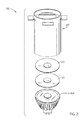
- FIG. 7 depicts an exploded view of an LED lamp with multiple accessories, according to certain embodiments of the present disclosure.
- FIG. 8A depicts an arrangement of a collimator design for LED lamp systems, according to certain embodiments of the present disclosure.
- FIG. 8B is a rear view of a collimator design for LED lamp systems, according to certain embodiments of the present disclosure.
- FIG. 8C is a rear view of a collimator design for LED lamp systems, according to certain embodiments of the present disclosure.
- FIG. 9A depicts an arrangement of a projector accessory for LED lamp systems, according to certain embodiments of the present disclosure.
- FIG. 9B is a front view of a projector accessory for LED lamp systems, according to certain embodiments of the present disclosure.
- FIG. 9C is a side view of a projector accessory for LED lamp systems, according to certain embodiments of the present disclosure.
- FIG. 10 is an exploded view of an LED lamp having magnet accessories, according to certain embodiments of the present disclosure.
- FIG. 11A is a top elevation view of an LED lamp assembly having magnet accessories, according to certain embodiments of the present disclosure.
- FIG. 11B is a rear elevation view of an LED lamp assembly having magnet accessories, according to certain embodiments of the present disclosure.
- FIG. 11C is a rear cutaway view of an LED lamp assembly having magnet accessories, according to certain embodiments of the present disclosure.
- FIG. 12 is a rear elevation view of an LED lamp assembly having magnet accessories, according to certain embodiments of the present disclosure.
- FIG. 13A is a perspective view of a beam shaping accessory and example attaching features for an LED lamp, according to some embodiments.
- FIG. 13B is a schematic showing relative intensities of light after passing through an oval pattern beam shaping accessory that has been treated to modulate an emanated light pattern as used with an LED lamp, according to some embodiments.
- FIG. 14 is a schematic showing relative intensities of light after passing through a uniform circular beam shaping accessory as used with an LED lamp, according to some embodiments.
- FIG. 15 is a schematic showing relative intensities of light after passing through a center-weighted circular beam shaping accessory as used with an LED lamp, according to some embodiments.
- FIG. 16 is a schematic showing relative intensities of light after passing through a rectangular pattern beam shaping accessory as used with an LED lamp, according to some embodiments.
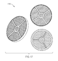
- FIG. 17 presents views of a honeycomb louver accessory and attach features as used with an LED lamp, according to some embodiments.
- FIG. 18 presents a perspective view of a half-dome diffuser accessory that can serve to block the glare from the light source as used with an LED lamp, according to some embodiments.
- FIG. 19 is an exploded view of components in an assembly of a prism lens configured for use with an LED lamp, according to some embodiments.
- FIG. 20 shows an assembly of components to form a prism lens configured for use with an LED lamp, according to some embodiments.
- FIG. 21 is an exploded view of components in an assembly of an accessory or a filter configured for use with an LED lamp, according to some embodiments.
- FIG. 22 shows an assembly of components to form a filter such as, for example, a color filter or a polarized configured for use with an LED lamp, according to some embodiments.
- FIG. 23A exemplifies an LED lamp assembly adapted for magnetically mounted concentric baffles for LED lamp systems, according to some embodiments.
- FIG. 23B shows a light pattern emanating from an LED lamp assembly adapted for magnetically mounted concentric baffles for LED lamp systems, according to some embodiments.
- FIG. 24 shows a series of legacy baffles that can be improved for use in an LED lamp assembly adapted for magnetically mounted concentric baffles for LED lamp systems, according to some embodiments.
- FIG. 25A is a chart showing the log distribution measurement of the intensity of the lamp without a baffle magnetically mounted concentric baffles for LED lamp systems, according to some embodiments.
- FIG. 25B is a chart showing the log distribution measurement of the intensity of the lamp with a baffle in an exemplary configuration using magnetically mounted concentric baffles for LED lamp systems, according to some embodiments.
- FIG. 26 is a chart showing beam and FWHM with no baffle, according to some embodiments.
- FIG. 27 exemplifies an LED lamp assembly having a magnetic mounting disk to implement magnetically mounted concentric baffles for LED lamp systems, according to some embodiments.
- FIG. 28 exemplifies an assembly having embedded baffles for magnetically mounted concentric baffles for LED lamp systems, according to some embodiments.
- FIG. 29 is a diagram showing angles where baffles are used as angular low-pass filters in systems having magnetically mounted concentric baffles for LED lamp systems, according to some embodiments.
- FIG. 30 is a diagram depicting extendable baffles for combining baffle effects in systems for magnetically mounted concentric baffles for LED lamp systems, according to some embodiments.
- FIG. 31 shows a light process in a cladded baffle used in systems for magnetically mounted concentric baffles for LED lamp systems, according to some embodiments.
- FIG. 32 shows a light process produced in a magnetically mounted reflective polarizer as used in systems for magnetically mounted concentric baffles for LED lamp systems, according to some embodiments.
- FIG. 33 is a diagram depicting one example of cascading baffles for combining baffle effects in systems for magnetically mounted concentric baffles for LED lamp systems, according to some embodiments.
- FIG. 34 superimposes profile shapes found in a range of lamp standards adapted to be used for providing active accessories in an LED lamp, according to some embodiments.
- FIG. 35 is a top view of a hybrid connector adapted to be used for providing active accessories in an LED lamp, according to some embodiments.
- FIG. 36 is a side view of a hybrid connector adapted to be used as a USB slave device for providing active accessories in an LED lamp, according to some embodiments.
- FIG. 37 is a side view of a hybrid connector adapted to be used as a USB master device for providing active accessories in an LED lamp, according to some embodiments.
- FIG. 38 is a side view of a hybrid connector adapted to be used as a power delivery device for providing active accessories in an LED lamp, according to some embodiments.
- FIG. 39 shows, as an example, the gamut for a blackbody radiator with a correlated color temperature (CCT) of 3000K for comparison with LED lamps with improved quality of light.
- CCT correlated color temperature
- FIG. 40 shows the diagram of FIG. 39 where an exemplary increased gamut is also shown for comparison.
- FIG. 41A shows an example of a spectrum with an increased overall gamut, according to some embodiments.
- FIG. 41B is a chart showing the CIELAB color space and the position of various colored objects illuminated by a reference source forming a reference gamut and the spectrum of FIG. 41A forming an increased gamut, for comparison, according to some embodiments.
- FIG. 42A is a chart showing the calculated SPD of an LED lamp having an increased gamut, according to some embodiments.
- FIG. 42B shows the corresponding gamut, for comparison, according to some embodiments.
- FIG. 43A is a chart showing the calculated SPD of an LED lamp having an increased gamut, according to some embodiments.
- FIG. 43B shows the corresponding gamut, for comparison, according to some embodiments.
- FIG. 44A is a chart showing the calculated SPD of an LED lamp having an increased gamut, according to some embodiments.
- FIG. 44B shows the corresponding gamut, for comparison, according to some embodiments.
- FIG. 45A is a chart showing the calculated SPD of an LED lamp having an increased gamut, according to some embodiments.
- FIG. 45B shows the corresponding gamut, for comparison, according to some embodiments.
- FIG. 46A is a chart showing the calculated SPD of an LED lamp having an increased gamut, according to some embodiments.
- FIG. 46B shows the corresponding gamut, for comparison, according to some embodiments.
- FIG. 47A is a chart showing the calculated SPD of an LED lamp having an increased gamut, according to some embodiments.
- FIG. 47B shows the corresponding gamut, for comparison, according to some embodiments.
- FIG. 48A is a chart showing the calculated SPD of an LED lamp having an increased gamut, according to some embodiments.
- FIG. 48B shows the corresponding gamut, for comparison, according to some embodiments.
- FIG. 49 is a chart showing the calculated SPD of an LED lamp having a CCT of 4000K and a low COI, according to some embodiments.
- FIG. 50A is a chart showing the calculated SPD of an LED lamp having an increased gamut, according to some embodiments.
- FIG. 50B is a chart showing the CIELAB color space and the position of various colored objects illuminated by a reference source forming a reference gamut and the spectrum of FIG. 26 forming an increased gamut for comparison.
- FIG. 50C is a chart showing the CIELUV (u′v′) color space and the chromaticities of a reference illuminant, for comparison.
- FIG. 51 shows the transmission of a short-wavelength suppressing filter, according to an embodiment.
- FIG. 52H , and FIG. 52I depict selected embodiments of the present disclosure in the form of lamp applications configured suited to be used in conjunction with the accessories disclosed herein.
- an accessory includes any mechanical, optical or electro-mechanical component or electrical component to be mated to an LED lamp.
- an accessory comprises an optically transmissive film, sheet, collimator, frame, plate, or combination of any of the foregoing.
- an accessory includes a mechanical fixture to retain the accessory in its mated position.
- an accessory is magnetically retained in place.
- FWHM refers to a measurement known in the art as “full-width half-maximum”.
- exemplary is used herein to mean serving as an example, instance, or illustration. Any aspect or design described herein as “exemplary” is not necessarily to be construed as preferred or advantageous over other aspects or designs. Rather, use of the word exemplary is intended to present concepts in a concrete fashion.
- compositions of wavelength-converting materials referred to in the present disclosure comprise various wavelength-converting materials.
- Wavelength conversion materials can be ceramic or semiconductor particle phosphors, ceramic or semiconductor plate phosphors, organic or inorganic downconverters, upconverters (anti-stokes), nano-particles, and other materials which provide wavelength conversion. Some examples are listed below:
- M(II) is at least one divalent cation
- M(I) is at least one monovalent cation
- M(III) is at least one trivalent cation
- H is at least one monovalent anion
- A is a luminescence activator doped in the crystal structure.
- a phosphor has two or more dopant ions (i.e., those ions following the colon in the above phosphors), this is to mean that the phosphor has at least one (but not necessarily all) of those dopant ions within the material. That is, as understood by those skilled in the art, this type of notation means that the phosphor can include any or all of those specified ions as dopants in the formulation.
- nanoparticles, quantum dots, semiconductor particles, and other types of materials can be used as wavelength converting materials.
- the list above is representative and should not be taken to include all the materials that may be used within embodiments described herein.
- an LED lamp comprises a lens having a center and a diameter, a first magnet attached to the center of the lens, a first accessory disposed on the lens, and a second magnet attached to the center of the first accessory wherein the first magnet and the second magnet are configured to retain the first accessory against the lens.
- the magnets are configured such that the magnetic force between the first magnet and the second magnet enable the self-centering of the accessory on to the lamp.
- FIG. 1A depicts an assembly 100 of an LED lamp of an embodiment having improved accessories for LED lamp systems.
- the MR16 lamp with lens 106 comprises an LED lamp with an installed accessory.
- FIG. 1B shows an exploded view of an LED lamp 150 with an accessory in a system having improved accessories for LED lamp systems.
- FIG. 1B shows an example of an LED lamp 150 having an MR16 form factor including a heat sink 120 .
- a lens 106 is attached to the heat sink 102 or other part of the lamp.
- the lens 106 comprises a folded total internal reflection lens.
- a first magnet e.g., magnet 102 1
- An accessory 104 e.g., a plastic accessory
- a second magnet e.g., magnet 102 2
- the opposing magnets e.g., magnet 102 1 , magnet 102 2
- the first and second opposing magnets can be configured to retain the accessory against the lens.
- the opposing magnets may have an opposite polarity.
- the accessory 104 may have substantially the same diameter as the lens, and in certain embodiments cover an optical region of the lens such as, for example, greater than 90% of the optical aperture of the LED lamp.
- the diameter of the accessory is from about 99% to 101% of the diameter of the lens, from about 95% to 105% the diameter of the lens, and in certain embodiments from about 90% to about 110% the diameter of the lens.
- the accessory comprises a transparent film such as, for example, a plastic film.
- the accessory may be a plate made of light transmissive material including plastic or glass.
- the accessory is selected from a diffuser, a color filter, a polarizer, a linear dispersion element, a projector, a louver, a baffle, and/or any combination of any of the foregoing.
- the first magnet and the first accessory have a combined thickness of less than about 5 mm, less than about 3 mm, less than about 1 mm, less than about 0.5 mm, and in certain embodiments, less than about 0.25 mm.
- a metallic member may replace one of the magnets, and may serve to accept a mechanically mated accessory.
- a metallic member e.g., using iron, nickel, cobalt, certain steels and/or other alloys, and/or other rigid or semi-rigid materials
- Any one or more known-in-the-art techniques can be applied to the design of the lens 106 (and/or lens subassembly) so as to accommodate a mechanically mated accessory.
- the aforementioned mechanical mating techniques may comprise a mechanical fixture such as a ring clip member, a bayonet member, a screw-in ring member, a leaf spring member, a hinge, or a combination of any of the foregoing. Any of the mating techniques disclosed herein can further serve to center the accessory upon installation and/or during use.
- FIG. 2 shows an exploded view 200 of an LED lamp with multiple accessories in a system having improved accessories for LED lamp systems.
- an LED lamp comprises a second accessory 202 disposed adjacent to a first accessory 104 .
- a second magnet is attached to the center of the second accessory and is used to affix the second accessory to the lamp.
- a third accessory 203 can be attached.
- a third accessory can be a projection frame (as shown), a collimator (see FIG. 8A ), or other accessory or combination of accessories.
- a collimator is a tube with walls that attenuates light, or are opaque (e.g., do not transmit light).
- the purpose of the collimator is to block or “cut off” or reduce the projection of high angle light coming from the lamp.
- the collimator can be formed of a tube with openings such as, for example, one opening at each end of the tube. At the end near the lamp, light enters the tube and the low angle light exits the tube at the other end of the collimator opening whereas high angle light is absorbed by and/or is extracted by the collimator walls.
- the length of the collimator can be determined, at least in part, by the amount of high angle light emitted by the lamp.
- a projection frame is similar to a collimator with the addition of a set of light frame features such as, for example, shatters, baffles, and/or louvers, positioned at the output end of the collimator.
- the light frame features are positioned a distance away from the lens, and as such, features formed by the shape of the frame can be projected on the wall.
- the frame for example may comprise a set of baffles that block, direct, and/or reflect at least part of the light to form any arbitrary set of patterns, for example, rectangular, square, oval, and/or triangular patters of the projected light from the lamp.
- the frame may have a silhouette image that is designed to be projected onto a surface such as a wall.
- LED lamp can any include any type of LED illumination source including lamp types that emit directed light where the light distribution is generally directed within a single hemisphere.
- lamp types include, for example, lamps having form factors such as MR, PAR, BR, ER, or AR. Table 1 below lists a subset of specific designations of the aforementioned form factors.
- G-type lamps such as G4, GU4, GY4, GZ4, G5, G5.3, G5.3-4.8, GU5.3, GX5.3, GY5.3, G6.35, GX6.35, GY6.35, GZ6.35, G8, GY8.6, G9, G9.5, GU10, G12, G13, G23, GU24, G38, GX53.
- a lens In certain lamps such as an ER lamp, the lens is referred to as a shield.
- a lens includes shields which do not substantially serve to divert light.
- Accessories and methods of attached accessories disclosed herein may be used with any suitable LED lamp configuration such as, for example, any of those disclosed in Table 1, and/or those configurations disclosed in Table 2, and/or those configurations disclosed in Table 3, and/or those configurations disclosed as G-type lamps above.
- FIG. 1A and FIG. 2 describe accessories attached at the central axis of the lamp/lens.
- the accessories can also be attached, mechanically or magnetically at other locations.
- the attachment point may be made near the perimeter of the lens or at the perimeter of the lamp form factor envelope.
- Various embodiments wherein the accessories are mechanically or magnetically attached at other locations are disclosed herein.
- FIG. 3A illustrates an embodiment of the present disclosure. More specifically, FIG. 3A and FIG. 3B illustrate embodiments of MR16 form factor-compatible LED lighting sources 300 having a GU 5.3 form factor-compatible base 320 .
- GU 5.3 MR16 lighting sources typically operate at 12 volts, alternating current (e.g., VAC).
- LED lighting source 300 is configured to provide a spot beam angle less than 15 degrees. In other embodiments, LED lighting sources may be configured to provide a flood light having a beam angle greater than 15 degrees.
- an LED assembly may be used within LED lighting source 300 . Advanced LED assemblies are currently under development by the assignee of the present patent application.
- LED lighting source 300 may provide a peak output of greater than about 1,000 candelas (or greater than 100 lumens).
- the center beam candle power may be greater than 10,000 candela or 100,000 candela with associated light levels greater than 1000 lumens or 5000 lumens.
- Various embodiments of the present disclosure achieve the same or higher brightness than conventional halogen bulb MR16 lights.
- FIG. 3B illustrates a modular diagram according to various embodiments of the present disclosure.
- an LED lighting source 400 includes a lens 410 , a light source in the form of an LED module/assembly 420 , a heat sink 430 , a base module 440 , a mechanically-retained accessory 460 , and a retainer 470 .
- the modular approach to assembling a lighting source 400 can reduce the manufacturing complexity, reduce manufacturing costs, and increase the reliability of such lighting sources.
- lens 410 and mechanically-retained accessory 460 may be formed from transparent material such as glass, polycarbonate, acrylic, COC material, or other material.
- the lens 410 may be configured in a folded path configuration to generate a narrow output beam angle. Such a folded optic lens enables embodiments of the lighting source 400 to have a tighter columniation of output light than is normally available from a conventional reflector of equivalent depth.
- the mechanically-retained accessory 460 may perform any of the function or functions as previously described for accessories.
- lens 410 may be secured to a heat sink 430 by means of one or more clips integrally formed on the edge of the reflecting lens 410 .
- the reflecting lens 410 may also be secured using an adhesive compound disposed proximate to where the integrated LED assembly 420 is secured to the heat sink 430 .
- separate clips may be used to restrain reflecting lens 410 .
- These clips may be formed, for example, of heat resistant plastic material that may be white colored to reflect backward scattered light back through the lens.
- lens 410 may be secured to a heat sink 430 using the clips described above.
- lens 410 may be secured to one or more indents of the heat sink 430 , as will be illustrated below in greater detail.
- FIG. 3A and FIG. 3B are merely illustrative embodiments.
- the particulars of the basic LED lamp components 445 can vary from one LED lamp to another, and the configuration or selection of any one or more particular members of the basic LED lamp components 445 may result in an assembly having certain characteristic such as efficiency, brightness, color, thermal properties, and/or others.
- integrated LED assemblies and modules may include multiple LEDs such as, for example, 36 LEDs arranged in a series, in parallel series (e.g., three parallel strings of 12 LEDs in series), or other configurations. In certain embodiments, any number of LEDs may be used such as, for example, 1, 10, 16, or more. In certain embodiments, the LEDs may be electrically coupled serially or in any other appropriate configuration.
- the targeted power consumption for LED assemblies is less than 13 W. This is much less than the typical power consumption of halogen-based MR16 lights (50 W). Accordingly, embodiments of the present disclosure are capable of matching the brightness or intensity of halogen-based MR16 lights, but using less than 20% of the energy.
- the LED assemblies may be configured for higher power operation such as greater than 13 W and incorporated into higher-output lamp form factors such as PAR30, PAR38, and other lamp form factors.
- an LED assembly can be incorporated into a luminaire and the lens assembly can accommodate accessorizing according to the embodiments provided by the present disclosure, which is not limited to retrofit lamps.
- the LED assembly 420 is directly secured to the heat sink 430 to dissipate heat from the light output portion and/or the electrical driving circuits.
- the heat sink 430 may include a protrusion portion 450 to be coupled to electrical driving circuits.
- LED assembly 420 typically includes a flat substrate such as silicon or the like. In various embodiments, it is contemplated that an operating temperature of the LED assembly 420 may be on the order of 125° C. to 140° C.
- the silicon substrate is then secured to the heat sink using a high thermal conductivity epoxy (e.g., thermal conductivity ⁇ 96 W/mk).
- thermoplastic/thermoset epoxy may be used such as TS-369, TS-3332-LD, or the like, available from Tanaka Kikinzoku Kogyo K.K. Other epoxies may also be used.
- no screws are used to secure the LED assembly to the heat sink, however, screws or other fastening means may be used in other embodiments.
- heat sink 430 may be formed from a material having a low thermal resistance/high thermal conductivity.
- still other alloys such AL 1100, or the like may be used.
- a die cast alloy with thermal conductivity as low as 96 W/mk is used.
- heat sink 430 may include other metals such as copper, or the like.
- the heat sink 430 has been measured to have a thermal resistance of approximately 8.5° C./W, and the heat sink 430 has been measured to have a thermal resistance of approximately 7.5° C./W. With further development and testing, it is believed that a thermal resistance of as little as 6.6° C./W may be achieved. In view of the present disclosure, one of ordinary skill in the art will be able to envision other materials having different thermal properties.
- a base module 440 in FIG. 3B provides a standard GU 5.3 physical and electronic interface to a light socket.
- a cavity within base module 440 includes high temperature resistant electronic circuitry used to drive an LED assembly 420 .
- an input voltage of 12 VAC to the lamps are converted to 120 VAC, 40 VAC, or other voltage by the LED driving circuitry.
- the driving voltage may be set depending upon the specific LED configurations (e.g., series, parallel/series, etc.) desired.
- protrusion portion 450 extends within the cavity of base module 440 .
- the shell of base module 440 may be formed from an aluminum alloy or a zinc alloy and/or may be formed from an alloy similar to that used for heat sink. In one example, an alloy such as AL 1100 may be used. In other embodiments, high temperature plastic material may be used. In some embodiments, instead of being separate units, base module 440 may be monolithically formed with heat sink 430 .
- a portion of the LED assembly 420 (silicon substrate of the LED device) contacts the heat sink 430 in a recess within the heat sink. Additionally, another portion of the LED assembly 420 (containing the LED driving circuitry) is bent downwards and is inserted into an internal cavity of base module 440 .
- a potting compound may be provided to facilitate a transfer of heat from the LED driving circuitry to the shell of the base assemblies and to facilitate transfer of heat from the silicon substrate of the LED device.
- the potting compound may be applied in a single step to the internal cavity of base module 440 and/or to the recess within heat sink 430 .
- a compliant potting compound such as Omegabond® 200 available from Omega Engineering, Inc. or 50-1225 from Epoxies, Etc. may be used.
- other types of heat transfer materials may be used.
- FIG. 4A and FIG. 4B illustrate an embodiment of the present disclosure. More specifically, FIG. 4A illustrates an LED package subassembly (LED module) according to certain embodiments. More specifically, a plurality of LEDs 500 is illustrated as being disposed upon a substrate 510 . In some embodiments, the plurality of LEDs 500 may be connected in series and powered by a voltage source of approximately 120 VAC. To enable a sufficient voltage drop (e.g., 3 to 4V) across each LEDs 500 , in various embodiments 30 to 40 LEDs may be used. In certain embodiments, 27 to 39 LEDs may be coupled in series. In other embodiments, LEDs 500 are connected in parallel series and powered by a voltage source of approximately 40 VAC.
- a voltage source of approximately 120 VAC.
- the plurality of LEDs 500 include 36 LEDs that may be arranged in three groups each having 12 LEDs 500 coupled in series. Each group is thus coupled in parallel to the voltage source (40 VAC) provided by the LED driver circuitry such that a sufficient voltage drop (e.g., 3 to 4V) is achieved across each LED 500 .
- a sufficient voltage drop e.g., 3 to 4V
- other driving voltages may be used, and other arrangements of LEDs 500 may also be employed.
- the LEDs 500 are mounted upon a silicon substrate 510 , or other thermally conductive substrate.
- a thin electrically insulating layer and/or a reflective layer may separate LEDs 500 and the silicon substrate 510 .
- Heat produced from LEDs 500 may be transferred to the silicon substrate 510 and/or to a heat sink by means of a thermally conductive epoxy, as discussed herein.
- the silicon substrate is approximately 5.7 mm ⁇ 5.7 mm in size, and approximately 0.6 mm in depth, or the silicon substrate is approximately 8.5 mm ⁇ 8 mm in size, and approximately 0.6 mm in depth.
- the dimensions may vary according to specific lighting requirements. For example, for lower brightness intensity, fewer LEDs may be mounted upon the substrate and accordingly the substrate may decrease in size. In other embodiments, other substrate materials may be used and other shapes and sizes may also be used.
- a ring of silicone e.g., silicon dam 515
- LEDs 500 are disposed around LEDs 500 to define a well-type structure.
- a phosphorus bearing material is disposed within the well structure.
- LEDs 500 provide a blue-emitting, a violet-emitting, or a UV-emitting light output.
- the phosphorous bearing material is excited by the output light, and emits white light output.
- a number of bond pads 520 may be provided on substrate 510 (e.g., 2 to 4 bond pads). Then, a conventional solder layer (e.g., 96.5% tin and 5.5% gold) may be disposed upon silicon substrate 510 , such that one or more solder balls 530 are formed thereon.
- a conventional solder layer e.g., 96.5% tin and 5.5% gold
- four bond pads 520 are provided, one at each corner, two for each power supply connection. In other embodiments, only two bond pads may be used, one for each AC power supply connection.
- FIG. 4A shows a flexible printed circuit (FPC) 540 .
- FPC 540 may include a flexible substrate material such as a polyimide, such as KaptonTM from DuPont, or the like.
- FPC 540 may have a series of bonding pads 550 for bonding to silicon substrate 510 , and bonding pads 550 for coupling to the high supply voltage (e.g., 120 VAC, 40 VAC, etc.).
- the high supply voltage e.g. 120 VAC, 40 VAC, etc.
- an opening 570 is provided through which LEDs 500 will shine through.
- FPC 540 may be used in the embodiments of the present disclosure.
- a series of cuts 580 may be made upon FPC 540 to reduce the effects of expansion and contraction of FPC 540 with respect to substrate 510 .
- a different number of bonding pads 550 may be provided such as two bonding pads.
- FPC 540 may be crescent shaped, and opening 570 may not be a through hole.
- other shapes and sizes for FPC 540 may be used consistent with present patent disclosure.
- substrate 510 is bonded to FPC 540 via solder balls 530 , in a conventional flip-chip type arrangement to the top surface of the silicon.
- the FPC is electrically isolated from the heat transfer surface of the silicon. This allows the entire bottom surface of the silicon substrate 510 to transfer heat to the heat sink. Additionally, this allows the LED to be bonded directly to the heat sink to maximize heat transfer instead of a printed circuit board material that typically inhibits heat transfer. As can be seen in this configuration, LEDs 500 are thus positioned to emit light through opening 570 .
- the potting compound discussed above may also be used as an under fill to seal the space (e.g., see cuts 580 ) between substrate 510 and FPC 540 .
- the LED package submodule or assembly 420 is thus constructed.
- the LEDs 500 may be positioned to emit light into the cavity of the lamp, and the LEDs are powered by means of discrete conductors.
- the LEDs may be tested for proper operation, and such testing can be done after the LED lamp is in a fully-assembled or in a partially-assembled state.
- FIG. 5A and FIG. 5B illustrate flow diagrams of manufacturing processes according to embodiments of the present disclosure. In certain embodiments, some of the manufacturing processes may occur in parallel or in series. For understanding, reference may be given to features in prior figures.
- the following process may be performed to form an LED assembly/module.
- a plurality of LEDs 500 are provided upon an electrically insulated silicon substrate 510 and wired, step 600 .
- a silicone dam 515 is placed upon the silicon substrate 510 to define a well, which is then filled with a phosphor-bearing material, step 610 .
- the silicon substrate 510 is bonded to a flexible printed circuit 540 , step 620 .
- a solder ball and flip-chip soldering may be used for the soldering process in various embodiments.
- a plurality of electronic driving circuit devices and contacts may be soldered to the flexible printed circuit 540 , step 630 .
- the contacts are for receiving a driving voltage of approximately 12 VAC.
- the electronic circuit devices in various embodiments, are capable of sustained high-temperature operation, (e.g., 120° C.).
- the second portion of the flexible printed circuit including the electronic driving circuit is inserted into the heat sink and into the inner cavity of the base module, step 640 .
- the first portion of the flexible printed circuit is then bent approximately 90 degrees such that the silicon substrate is adjacent to the recess of the heat sink.
- the back side of the silicon substrate is then bonded to the heat sink within the recess of the heat sink using an epoxy, or the like, step 650 .
- one or more of the heat producing the electronic driving components/circuits may be bonded to the protrusion portion of the heat sink, step 660 .
- electronic driving components/circuits may have heat dissipating contacts (e.g., metal contacts). These metal contacts may be attached to the protrusion portion of the heat sink via screws (e.g., metal, nylon, or the like).
- a thermal epoxy may be used to secure one or more electronic driving components to the heat sink.
- a potting material is used to fill the air space within the base module and to serve as an under fill compound for the silicon substrate, step 670 .
- a reflective lens may be secured to the heat sink, step 680 , and the LED light source may then be tested for proper operation, step 690 .
- the base subassembly/modules that operate properly may be packaged along with one or more optically transmissive member offerings and/or a retaining ring (described above), step 700 , and shipped to one or more distributors, resellers, retailers, or customers, step 710 .
- the modules and separate optically transmissive member offerings may be stocked, stored, or the like.
- the optically transmissive member offerings may be in the form of lenses.
- an end user desires a particular lighting solution, step 720 .
- the lighting solution may require different beam angles, different cut-off angles or roll-offs, different coloring, different field angles, and the like.
- the beam angles, the field angles, and the full cutoff angles may vary from the above, based upon engineering and/or marketing requirements. Additionally, the maximum intensities may also vary based upon engineering and/or marketing requirements.
- secondary optically transmissive members may be selected, step 730 .
- the selected lens may or may not be part of a kit for the lighting module.
- various optically transmissive members are provided with each lighting module, while in other examples, lighting modules are provided separately from the optically transmissive members.
- an assembly process may include attaching the retaining ring to one or more optically transmissive member and snapping the retaining ring into a groove of the heat sink, step 740 .
- a retaining ring is already installed for each optically transmissive member that is provided.
- the retaining ring cannot be removed by hand.
- a tool such as a thin screwdriver, pick, or the like must be used to remove a secondary optic lens (optically transmissive members) from the assembled unit.
- the restraint mechanism may be removed by hand.
- the assembled lighting unit may be delivered to the end-user and installed, step 750 .
- FIG. 6A and FIG. 6B illustrate embodiments of a heat sink according to certain embodiments of the present disclosure. More specifically, FIG. 6A illustrates a perspective view of a heat sink, and FIG. 6B illustrates a cross-section view of the heat sink.
- a heat sink 800 is illustrated including a number of heat dissipating fins 810 .
- fins 810 may include a mechanism for mating onto the retaining ring/optically transmissive members. As illustrated in the example in FIG. 6A and FIG. 6B , the mating mechanism includes indentations 820 on fins 810 . In some embodiments, each of fins 810 may include an indentation 820 , whereas in other embodiments, less than all of fins 810 may include an indentation. In other embodiments, the mating mechanism may include the use of an additional clip, a clip on the reflective optics, or the like.
- FIG. 7 depicts an exploded view of an LED lamp with multiple accessories according to certain embodiments of the present disclosure.
- the optically transmissive members may be coupled to an intermediate grille, or the like, that is coupled to the heat sink and/or reflective lens. Accordingly, embodiments of the present disclosure are applicable for use in wide-beam light sources or in narrow-beam light sources.
- FIG. 8A depicts an arrangements of a collimator 812 accessory for LED lamp systems.
- the arrangement 850 shows an LED lamp 150 comprising a lens having a center and a diameter to which is attached a first magnet so as to accommodate a collimator accessory where the collimator accessory is disposed on the lens and held in place by a second magnet 102 2 attached to the center of the collimator accessory (see FIG. 8B ).
- FIG. 8B is a rear view 860 of a collimator design for LED lamp systems.
- the collimator is operable for blocking side-emanating light.
- the surfaces of the collimator may be textured or polished or anodized or painted for ornamental or other purposes.
- FIG. 8C is a rear view 890 of a collimator design for LED lamp systems.
- the collimator is operable for blocking side-emanating light, and includes a magnet 102 2 affixed to a diffuser 822 , which is integrated into the collimator 812 .
- FIG. 9A depicts an arrangement 900 of a projector accessory 910 for LED lamp systems.
- the term “projector accessory” as used herein refers to an accessory attached to an LED lamp or other LED light source.
- the projector accessory 910 is attached to an LED lamp by means of magnetic attraction (also see the collimator 812 of FIG. 8A and FIG. 8B ).
- the projector accessory 910 comprises secondary optics and adjustable baffles.
- the arrangement 900 shows an LED lamp 150 comprising a lens having a center and a diameter to which is attached a first magnet so as to accommodate a projector accessory where the projector accessory is disposed on the lens and held in place by a second magnet 102 2 attached to the center of the projector accessory (see FIG.
- the projector accessory 910 has an adjustable aperture and focal lens(s) that allows manipulation of the projected light beam.
- the LED lamp comprises a lamp output mechanical aperture.
- the LED lamp comprises a first or second lens that is configured to cover more than 90% of the lamp output mechanical aperture.
- FIG. 9B is a front view 950 of a projector accessory 910 for LED lamp systems, according to certain embodiments of the present disclosure.
- the projector accessory 910 comprises a housing 904 , into which are mated a plurality of adjustable baffles 903 .
- the baffles shown are substantially rectilinear, however baffles may be formed into a non-rectangular or irregular shape.
- some embodiments of projector accessory 910 have one or more focal lens(s) that provide for manipulation of the projected light beam so as to focus a pattern on a surface (e.g., a wall, a painting, a door) that is positioned at a predetermined length from the focal lens.
- FIG. 9C is a side view 975 of a projector accessory for LED lamp systems.
- the rear view shows magnet 102 2 .
- FIG. 10 is an exploded view 1000 of an LED lamp having magnet accessories.
- an LED lamp is affixed to a lens 106 having a center and a diameter for mating to a first magnet 102 1 attached to the center of the lens 106 .
- a first accessory 104 is disposed over the lens 106 using a second magnet 102 2 mechanically attached to the center of the first accessory 104 .
- the first magnet 102 1 and the second magnet 102 2 are configured to retain the first accessory 104 against the lens 106 .
- a second accessory 202 is disposed over the first accessory 104 using a third magnet 102 3 mechanically attached to the center of the second accessory 202 .
- the magnet 102 1 serves to block at least a portion of the unwanted high-angle light, and a reduction in glare is in response to the shape and position of the magnet.
- the magnet 102 1 may have a special reflector coat on it to enhance the reflection of the high angle light back into or toward the general direction of the LED light source.
- the magnet 102 1 may be coated with a material to absorb the light.
- the magnet 102 1 may have an untreated surface that provides for tuned absorption and/or reflection.
- the magnet may be embodied as a disk, as a ring, as a doughnut, or any other appropriate shape.
- FIG. 11A is a top elevation view 1100 of an LED lamp assembly having magnetic accessories.
- a lens 106 is attached to a heat sink 120 .
- the design of lens 106 includes a magnet (e.g., a ring-shaped or doughnut magnet 102 3 ) which can hold accessory 104 to the lens 106 .
- the first magnet (doughnut magnet 102 3 ) and second magnet (e.g., 102 4 ) are opposing magnets that can be configured to retain the accessory 104 against the lens 106 .
- the opposing magnets 102 3 and 102 4 may have the opposite polarity.
- the shape and position of the opposing magnets is such that an attachment is self-centering with respect to the lens 106 upon installation.
- FIG. 11B is a rear elevation view 1120 of an LED lamp assembly having magnetic accessories.
- the doughnut magnet 102 3 is shaped and affixed to lens 106 in a particular position so as to occlude only a portion of the light emanating from the LED light source.
- the shape and position of the doughnut magnet serves to attenuate glare (see emanated light pattern 1104 ).
- FIG. 11C is a rear cutaway view 1140 of an LED lamp assembly having magnetic accessories.
- the doughnut magnet 102 3 is shaped and affixed to lens 106 in a particular position so as to reflect a portion of the light emanating from the LED light source back toward the general direction of the LED light source.
- the treated surface 1102 of the doughnut magnet 102 3 is treated so as reflect light in a particular pattern and direction.
- a particular pattern and direction can be predetermined, and the selection of the shape, position, and surface treatment can be tuned so as to modulate the light (see emanated light pattern 1104 ) using the predetermined particular pattern and direction.
- FIG. 12 is a rear elevation view 1200 of an LED lamp assembly having magnetic accessories.
- the disk magnet 102 5 is shaped and affixed to lens 106 in a particular position so as to occlude only a portion of the light emanating from the LED light source.
- the shape and position of the disk magnet serves to attenuate glare (see emanated light pattern 1104 ).
- a particular pattern and direction can be predetermined, and the selection of the shape, position and surface treatment of the disk magnet 102 5 and its treated surface 1102 2 can be tuned so as to modulate the light (see emanated light pattern 1204 ) using the predetermined particular pattern and direction.
- FIG. 13A is a perspective view of a beam shaping accessory 13 A 00 and example attaching features for an LED lamp. The attaching features of FIG. 13A are further described infra.
- FIG. 13B is a schematic 13 B 00 showing relative intensities of light after passing through an oval pattern beam shaping accessory that has been treated to modulate an emanated light pattern as used with an LED lamp.
- FIG. 14 is a schematic 1400 showing relative intensities of light after passing through a uniform circular beam shaping accessory 1402 as used with an LED lamp.
- FIG. 15 is a schematic 1500 showing relative intensities of light after passing through a center-weighted circular beam shaping accessory 1502 as used with an LED lamp.
- FIG. 16 is a schematic 1600 showing relative intensities of light after passing through a rectangular pattern beam shaping accessory 1602 as used with an LED lamp.
- FIG. 17 presents views of a honeycomb louver accessory 1700 and attach features as used with an LED lamp.
- the honeycomb shape of the accessory is used to cancel the incident glare from the light source and to direct the light to a specific area of interest.
- FIG. 18 presents a perspective view of a half-dome diffuser accessory 1800 that can serve to block the glare from the light source 1800 . Also shown are attach features as used with an LED lamp.
- FIG. 19 is an exploded view of components in an assembly of a prism lens 1900 configured for use with an LED lamp.
- Various techniques could be used to secure the magnet to a lens or to the aforementioned accessories. Such techniques are not limited to one or another of the various methods. Non-limiting examples are:
- a thin magnet is used for the specific application of affixing the magnet on the face of the lens.
- the cap geometry is designed to encapsulate the thin magnet on the lens (which assembly is shown in FIG. 20 ).
- FIG. 20 shows an assembly of components to form a prism lens 2000 configured for use with an LED lamp.
- FIG. 21 is an exploded view of components in an assembly of an accessory or a filter 2100 configured for use with an LED lamp.
- the accessory shown has progressive pockets (e.g., having a first mesa 2106 and a second mesa 2108 ) for receiving the magnet and for receiving the cap.
- the magnet is placed in the pocket, then the cap is placed on top of the magnet where the edges of the cap makes contact with a pocket.
- This assembly is then placed in an ultrasonic welding machine that joins the cap to the accessory.
- Different thickness of magnets can be used. In some cases a different thickness is used for the accessory as compared with the thickness used for the lens.
- the pockets are designed such that the same cap can be used to encapsulate the magnet on either the lens or the accessory.
- FIG. 22 shows an assembly of components to form a filter 2200 such as, for example, a color filter or a polarizer configured for use with an LED lamp.
- a filter 2200 such as, for example, a color filter or a polarizer configured for use with an LED lamp.
- an illumination source is configured to output light having a user-modifiable beam characteristic.
- Such an illumination source comprises an LED light unit configured to provide a light output in response to an output driving voltage; a driving module coupled to the LED light unit, wherein the driving module is configured to receive an input driving voltage and is configured to provide the output driving voltage; a heat sink coupled to the LED light unit, wherein the heat sink is configured to dissipate heat produced by the LED light unit and by the driving module; a reflector coupled to the heat sink, wherein the reflector is configured to receive the light output, and wherein the reflector is configured to output a first light beam having a first beam characteristic; and a lens coupled to the heat sink, wherein the lens is configured to receive the first light beam having the first beam characteristic, and wherein the lens is configured to output a second light beam having a second beam characteristic, wherein the lens is selected by the user to achieve the second beam characteristic and wherein the lens is coupled to the heat sink by the user.
- an illumination source comprising a transmissive optical lens and a retaining ring coupled to the transmissive optical lens, wherein the retaining ring is configured to couple the transmissive optical lens to the heat sink.
- a retaining ring comprises an incomplete circle.
- a lens that is coupled to a heat sink is configured to require use of a tool to decouple the lens from the heat sink.
- the intensity for the light output from the illumination source is greater than approximately 1500 candela.
- the first beam characteristic is selected from a beam angle, a cut-off angle, a roll-off characteristic, a field angle, and/or a combination of any of the foregoing.
- a heat sink comprises a plurality of heat dissipation fins wherein at least one of the plurality of heat dissipation fins includes a retaining mechanism, and a lens is configured to be coupled to at least one of the plurality of heat dissipation fins by means of a retaining mechanism.
- a retaining mechanism is selected from an indentation on the heat dissipation fin, a clip coupled to the heat dissipation fin, and/or a combination thereof.
- a heat sink comprises an MR16 form factor heat sink.
- a driving module comprises a GU5.3 compatible base.
- Certain embodiments provided by the present disclosure include methods of providing accessories and components for assembling the accessories to a user. Certain embodiments further provide for methods of assembling accessories provided by the present disclosure.
- a light source comprising an LED light unit configured to provide a light output in response to an output driving voltage; a driving module coupled to the LED light unit, wherein the driving module is configured to receive an input driving voltage and is configured to provide the output driving voltage; a heat sink coupled to the LED light unit, wherein the heat sink is configured to dissipate heat produced by the LED light unit and by the driving module, and a reflector coupled to the heat sink, wherein the reflector is configured to receive the light output, and wherein the reflector is configured to output a light beam having a first beam characteristic; receiving a user selection of a lens to achieve a second beam characteristic, wherein the lens is configured to receive the light beam having the first beam characteristic and wherein the lens is configured to output a light beam having the second beam characteristic; receiving the lens in response to the user selection of the lens, separate from the light source; and coupling the lens to the light
- the lens comprises an optical lens and a retaining ring coupled to the optical lens, wherein the retaining ring is configured to couple the optical lens to the heat sink and wherein coupling the lens to the heat sink comprises compressing the retaining ring about the optical lens; disposing the retaining ring that is compressed within a portion of the heat sink; and releasing the retaining ring such that the retaining ring is coupled to the portion of the heat sink.
- the retaining ring comprises a circular shaped metal.
- methods further comprise decoupling the lens from the heat sink using a tool wherein the decoupling step requires use of a tool to decouple the lens from the heat sink.
- the intensity for the light output is greater than approximately 1500 candela.
- the first beam characteristic is selected from a group consisting of: beam angle, cut-off angles, roll-offs characteristic, and/or field angle.
- the heat sink comprises a plurality of heat dissipation fins wherein at least one of the plurality of heat dissipation fins includes a retaining mechanism, and wherein coupling the lens to heat sink comprises coupling the lens to the at least one heat dissipation fin via the retaining mechanism.
- the retaining mechanism is selected from a group consisting of: an indentation on the heat dissipation fin, and a clip coupled to the heat dissipation fin.
- the heat sink comprises an MR16 form factor heat sink.
- the driving module comprises a GU5.3 compatible base.
- FIG. 23A exemplifies an LED lamp assembly 23 A 00 adapted for magnetically mounted concentric baffles for LED lamp systems.
- FIG. 23A shows the lamp and the baffle each with a magnetic ring.
- the ring is sized so as to coincide with the domain on this lamp from where little light is emerging.
- the particular lamp shown is of what is known as folded total internal reflection (TIR) where light (when no baffle is present) is not emerging from the center ring domain where the baffle is mounted due to the TIR effect that occurs at that center ring location.
- TIR folded total internal reflection
- FIG. 23B shows a light pattern 23 B 00 emanating from an LED lamp assembly adapted for magnetically mounted concentric baffles for LED lamp systems.
- FIG. 23B shows the lamp mounted with the concentric baffle by placing of the baffle magnetic surface over the lamp magnetic surface.
- FIG. 24 shows a series of legacy baffles 2400 that can be improved for use in an LED lamp assembly adapted for magnetically mounted concentric baffles for LED lamp systems.
- FIG. 25A is a chart 25 A 00 showing the log distribution measurement of the intensity of the lamp without a baffle magnetically mounted concentric baffles for LED lamp systems.
- FIG. 25B is a chart 25 B 00 showing the log distribution measurement of the intensity of the lamp with a baffle in an exemplary configuration using magnetically mounted concentric baffles for LED lamp systems.
- FIG. 25B shows the light intensity with the concentric baffle mounted.
- FIG. 26 is a chart 2600 showing beam and FWHM with no baffle in an exemplary configuration of an LED lamp ready to use magnetically mounted concentric baffles for LED lamp systems.
- the diagram shows beam and FWHM with no baffle. With the baffle these values do not change significantly.
- FIG. 27 exemplifies an LED lamp assembly 2700 having a magnetic mounting disk to implement magnetically mounted concentric baffles for LED lamp systems.
- This figure shows an embodiment with a magnetic mounting disk (no center hole).
- FIG. 28 exemplifies an assembly 2800 having embedded baffles for magnetically mounted concentric baffles for LED lamp systems.
- FIG. 29 is a diagram 2900 showing angles where baffles are used as angular low-pass filters in systems having magnetically mounted concentric baffles for LED lamp systems.
- the baffles are embedded within a plate made of transparent material such as polycarbonate, acrylic or glass.
- FIG. 30 is a diagram 3000 depicting extendable baffles for combining baffle effects in systems for magnetically mounted concentric baffles for LED lamp systems.
- Baffles can be easily mounted on other baffles using the magnetic mount.
- the baffle is an angular low pass filter as shown on FIG. 29 .
- T on FIG. 29 is doubled thus reducing the divergence angle.
- FIG. 31 shows a light process in a cladded baffle 3100 used in systems for magnetically mounted concentric baffles for LED lamp systems.
- the baffles are embedded within a plate made of transparent material such as polycarbonate, acrylic or glass.
- the baffles are embedded in the plastic similar to the way 3M venetian blinds are embedded in the 3M “privacy screens”.
- the baffles are made of absorbing cylindrical concentric rings as shown however, each one is covered on both sides with a coating of a low index material.
- a coating of a low index material is, for example, polycarbonate and the clad is, for example, a 1.32 index material.
- the advantage is that this way the low pass filter is a true angle device and is more efficient compared with uncladded baffles.
- FIG. 32 shows a light process produced in a magnetically mounted reflective polarizer 3200 as used in systems for magnetically mounted concentric baffles for LED lamp systems.
- a magnetically mounted reflective polarizer is added to the lamp.
- This can be on top of other elements such as magnetically mounted baffles or it can be standalone.
- This produces a polarized light source that is beneficial for many applications.
- the advantage of using the wire grid polarizer is that the polarizer can withstand high power densities and also serves as a polarization recycler where the reflected light is hitting the LED and scatters and some of it but will make it through on a second path.
- An additional retarder can be also used between the lamp and the polarizer and can be also magnetically mounted to improve recycling efficiency.
- FIG. 33 is a diagram 3300 depicting one example of cascading baffles for combining baffle effects in systems for magnetically mounted concentric baffles for LED lamp systems.
- FIG. 34 superimposes profile shapes 3400 found in a range of lamp standards adapted to be used for providing active accessories in an LED lamp.
- a home or business may have several lamp types installed. Creating a set of smart accessories that fit any/all of these lamp types, and communicate with each other and with a central computer in a consistent manner enables the consumer or business owner to monitor and control their environment efficiently and effectively.
- the accessories can have unique IDs and communicate with each other and a central computer using standard protocols like uPnP, DLNA, or other interoperable or interoperability protocols.
- FIG. 35 is a top view of a hybrid connector 3500 adapted to be used for providing active accessories in an LED lamp.
- USB universal serial bus
- a standard interface like a universal serial bus (USB) can be implemented using a simple connector with four or five terminals that carry power and data.
- USB provides the opportunity to leverage the vast ecosystem of systems and devices that have been built over the past few decades for PCs, CE devices, smartphones, etc., as well as the continuous evolution of the interface to accommodate new usages for consumers and businesses.
- FIG. 36 is a side view of a hybrid connector 3600 adapted to be serve as a USB connector for a slave device in an LED lamp.
- a lamp can be built with a standard microcontroller or microprocessor with associated software, and with or without persistent connectivity to other devices or a central computer.
- the microcontroller or microprocessor can be used for internal lamp functions like controlling the LED driver, storing operational data like hours of usage, current and temperature data, etc.
- a smart USB slave button By attaching a smart USB slave button, the functionality of the lamp can be extended to include wireless communication to other lamps and a central computer for lamp monitoring and control, connection to peripheral devices like a camera and sensors.
- FIG. 37 is a side view of a hybrid connector 3700 adapted to be used as a USB master device for providing active accessories in an LED lamp.
- a lamp can be built even without a microcontroller or microprocessor, yet supporting a simple USB-based readable storage that stores operational data of the lamp like hours of usage, current and temperature data, etc.
- a smart USB master button that has a microcontroller or microprocessor is connected to the lamp, that USB device can be read by the microcontroller or microprocessor on the smart button.
- the smart button can also integrate wireless networking to implement lamp monitoring and control, and can communicate with other lamps and/or can communicate with a central computer. It may also contain a camera and/or other sensors.
- FIG. 38 is a side view of a hybrid connector 3800 adapted to be used as a power delivery device for providing active accessories in an LED lamp.
- a lamp can be built with a device that provides power to the smart button connector.
- a smart USB master button that has a microcontroller or microprocessor is connected to the lamp, the lamp can be turned into a smart lamp.
- the smart button can integrate wireless networking to implement lamp monitoring and control and communication with other lamps and a central computer. It may also contain a camera and sensors. It may also contain readable storage that stores operational data of the lamp such as hours of usage, current and temperature data, etc.
- One embodiment disposes accessories on the face of the lamp, in a proximity that is thermally isolated from the heat source and high temperatures of the LED.
- the face of the lamp is open to the environment so as to facilitate heat dissipation of any electronics. Face-mounting further facilitates antenna placement (e.g., for wireless radio operation), and for camera and sensor operation. It also makes it easy to connect and disconnect accessories.
- CCT correlated color temperature shifting filter
- SPD lamp's spectral power distribution
- CCT is merely one characteristic of the SPD which can be modified by applying a filter.
- Other properties related to the quality of light include:
- gamut of the light source One possible quality of light metric is the gamut of the light source.
- gamut enhancement consider the methodology of using the 15 reflectance samples of the Color Quality Scale, then compute their chromaticity in CIELAB space under illumination by various sources and consider the gamut of the resulting points. This methodology is referred to as Qg in the Color Quality Scale.
- FIG. 39 shows, as an example, the gamut for a blackbody radiator with a correlated color temperature (CCT) of 3000K.
- CCT correlated color temperature
- the objects are distributed around the white point, and cover various hues. These hues are indicated by labels on the figure.
- the distance between the origin and each object is a measure of its saturation—objects farther from the origin correspond to a higher saturation, which can be desirable.
- the reference gamut 3902 is shown here and in several following figures.
- FIG. 40 shows the same diagram as FIG. 39 where an exemplary increased gamut is also shown for comparison to the reference gamut 3902 . It can be seen that the increased gamut 4002 covers a larger area than the reference gamut. Specifically, the gamut is increased in the purple and red region. A source with a CCT of 3000K which has this gamut will show more saturated reds and purples than a blackbody radiator.
- various sources are considered and compared to blackbody radiators of the same CCT. Also illustrated are the gamut enhancement as in FIG. 40 .
- FIG. 41A shows an example of a spectrum with an increased overall gamut.
- the spectrum resembles a blackbody radiator with a CCT of 3000K, with additional dips 4106 and peaks 4104 . These dips and peaks may be obtained by choosing the light-emitting elements (phosphor, LEDs) and, if needed, by additional filtering.
- the dips shown on this figure are very sharp, but this is not a necessary property—in some cases smoother dips provide a similar gamut increase.
- the corresponding increased gamut is also shown on FIG. 41B , and compared to a reference gamut.
- FIG. 41B is a chart showing the CIELAB color space and the position of various colored objects illuminated by a reference source forming a reference gamut and the spectrum of FIG. 41A forming an increased gamut 4102 for comparison.
- FIG. 42A is a chart showing the calculated SPD of an LED lamp having an increased gamut.
- FIG. 42B shows the corresponding gamut for comparison.
- FIG. 42A and FIG. 42B show another source with very similar gamut properties to FIG. 41A and FIG. 41B .
- the spectrum resembles an LED spectrum with additional dips and peaks.
- the spectrum contains a pronounced violet peak at 415 nm.
- FIG. 43A is a chart showing the calculated SPD of an LED lamp having an increased gamut.
- FIG. 43B shows the corresponding gamut.
- FIG. 43A and FIG. 43B show yet another source with increased gamut 4302 and with a spectrum which resembles an LED spectrum.
- peaks are present in the spectrum, and their width and position is chosen to increase the gamut. These peaks may correspond to a mixture of LED emission spectra and of phosphor emission spectra.
- the SPD is modified in order to increase saturation specifically for yellow or red objects.
- the SPD is modified in order to increase the saturation of human skin of a given ethnicity, or to increase the red content in the rendering of said skin tone.
- a possible metric for such cases is the chromaticity shift of a given reflectance sample.
- the increased saturation occurs for warm colors such as red, orange, pink rather than in colors such as yellow and blue. This is useful because end users frequently value warm colors the most.
- the SPD of the invention is designed such that the skin of a given ethnicity (such as Caucasian) has increased saturation, either directly radial (redder) or in a slightly non-radial direction (red-yellow).
- a given ethnicity such as Caucasian
- redder directly radial
- red-yellow slightly non-radial direction
- the skin of a Caucasian ethnicity undergoes a chromatic shift which is substantially along the b* direction of the CIELAB space.
- FIG. 44A is a chart showing the calculated SPD of an LED lamp having an increased gamut.
- FIG. 44B shows the corresponding gamut.
- FIG. 44A and FIG. 44B show an example of a spectrum with increased gamut 4402 in the green and red/purple regions.
- the spectrum resembles a blackbody radiator with additional dips.
- FIG. 45A is a chart showing the calculated SPD of an LED lamp having an increased gamut.
- FIG. 45B shows the corresponding gamut.
- FIG. 45A and FIG. 45B show another source with very similar gamut properties (e.g., increased gamut 4502 ).
- the spectrum resembles an LED spectrum with additional dips.
- FIG. 46A is a chart showing the calculated SPD of an LED lamp having an increased gamut.
- FIG. 46B shows the corresponding gamut.
- FIG. 46A and FIG. 46B shows an example of a spectrum with increased gamut in the yellow region (e.g., increased gamut 4602 ).
- the spectrum resembles a blackbody radiator with additional dips and peaks.
- FIG. 47A is a chart showing the calculated SPD of an LED lamp having an increased gamut.
- FIG. 47B shows the corresponding gamut.
- FIG. 47A and FIG. 47B show another source with similar gamut properties (e.g., increased gamut 4702 ).
- the spectrum resembles an LED spectrum with additional dips and peaks.
- CCT warm-white spectra
- the same approach can be used for any CCT. For instance, if a CCT of 5000K is desired, the spectrum may be designed to increase the gamut.
- FIG. 48A is a chart showing the calculated SPD of an LED lamp having an increased gamut.
- FIG. 48B shows the corresponding gamut.
- FIG. 48A and FIG. 48B show a source with a CCT of about 5000K.
- the spectrum resembles an LED spectrum, with additional dips and peaks.
- a large color contrast between two objects is desired.
- some diagnoses are formulated by considering the color difference between two tissues (in the case of skin conditions) or the color difference between oxygenated and non-oxygenated blood (diagnosis of cyanosis). Again, modifications in the spectrum similar to those described above can be designed to meet such a requirement.
- COI cyanosis observation index
- FIG. 49 shows a spectrum, according to such an embodiment, which spectrum has been designed (including the spectra of the phosphors and the amount of violet light) to obtain a low COI value of 0.59 and a CCT of 4000K.
- FIG. 50A is a chart showing the calculated SPD of an LED lamp having an increased gamut.
- FIG. 50B is a chart showing the CIELAB color space and the position of various colored objects illuminated by a reference source forming a reference gamut and the spectrum of FIG. 39 forming an increased gamut for comparison.
- FIG. 50C is a chart showing the CIELUV (u′v′) color space and the chromacities of a reference illuminant.
- FIG. 50A exemplifies such a source.
- the spectrum resembles an LED spectrum with additional dips.
- the gamut is increased (e.g., increased gamut 5002 ).
- the white point 5003 of the source is shown in the 1964 CIE (u′v′) color space. It is located below the blackbody locus 5004 . Also indicated is the white point of a blackbody radiator with the same CCT (3000K).
- the presence of violet light in the spectrum can be used to improve the quality of light. This can be done to improve the rendering of objects containing OBAs such as many manufactured white products. For instance, the amount of violet in the spectrum may be tuned to excite OBAs with enough intensity to reproduce the whiteness rendering of another source.
- FIG. 51 shows the transmission curve of a short-wavelength suppressing filter, according to an embodiment of the disclosure.
- the filter of FIG. 51 can be used, for instance, as an accessory on an LED lamp.
- a filter exhibiting the transmission characteristics of FIG. 51 removes radiation below 430 nm, which reduces the amount of damage caused to sensitive materials such as some works of art. It also reshapes the spectrum above 430 nm, such that the CCT, chromaticity, and values of Ra and R9 are maintained.
- suppression of short-wavelength light can be combined with the gamut-enhancing effects discussed above. This results in a filter which removes short-wavelength radiation while also increasing the gamut of the spectrum. This can be desirable for a variety of applications.
- the filter is designed specifically to enhance the vividness of a given color (such as red, blue, or other) and make it visually more pleasant.
- embodiments of the invention provide suppression of another spectral band while maintaining the quality of light. For instance, consider a situation where one may desire to remove cyan light from the spectrum (this could be due to some health concern, for instance). A simple filter which blocks cyan light with no other effect will result in a CCT and chromaticity shift, and in a modification of the source's CRI. On the other hand, embodiments of the invention provide a block in the cyan spectral range, and further reshape the spectrum outside this range so that CCT, chromaticity or CRI can be maintained.
- the spectrum may be tuned for optimal interaction with another device such as a photo or video camera.
- image capture devices use light sensors with color filters (typically red, green and blue) in order to capture color information.
- the filters can have cross-talk, e.g., the transmission window of two filters may overlap.
- Using a light source which possesses spectral gaps in the overlap regions can help subsequent treatment of the data to reproduce the images in the scene. This may be used in conjunction with software which takes the source spectrum into account in order to accurately reproduce colors.
- absorbing or reflecting filters can be formed on embodiments of the invention.
- the lamp whose spectrum is modified may be a general-purpose lamp, or it may be a lamp whose spectrum has already been optimized to operate in conjunction with an embodiment of the invention (for instance, an LED lamp with a properly chosen phosphor set which interacts properly with a specific filter).
- the filter can be of various constructions, for instance a filter can comprise a dielectric stack with particular transmission characteristics, and/or a color gel, and/or an absorbing material (such as an absorbing glass), etc.
- An apparatus comprising:
- an LED lamp e.g., including spot lamps and non-spot lamps, including candelabras
- an optical element e.g., a lens or diffuser
- the optical element mechanically affixed to the LED lamp, such that an initial light pattern is emanated out of the lamp
- a first accessory comprising a second fixture, wherein the first accessory is mated in proximity to the optical element using the first fixture and the second fixture;
- the first accessory is configured to modulate the initial light pattern into a modified light pattern.
- the first accessory is configured such that the modified light pattern has a Color Quality Scale gamut metric Qg in the range 1.10 to 1.40 and a Color Quality Scale fidelity metric Qf of 60 or higher.
- the first accessory is configured such that the initial light pattern and the modified light pattern have Color Quality Scale gamut metrics Qg, and the Qg of the modified light pattern is at least 5% larger than the Qg of the initial light pattern.
- the first accessory is configured such that the modified light pattern modifies a saturation of at least one of the following Color Quality Scale samples: VS1 (red), VS2 (red-orange), VS3 (orange), VS14 (red-pink), VS15 (pink); the saturation being increased by at least 5% versus a conventional lamp with a same correlated color temperature.
- the first accessory is configured such that the modified light pattern renders various Caucasian skins with a color distortion which is substantially along the CIELAB b* direction, with an increase in b* of at least 1 point.
- the first accessory is configured to render common OBA-containing white objects such that their color is substantially similar to that under a natural light source of a same correlated color temperature.
- FIG. 52A through FIG. 52I depict embodiments of the present disclosure in the form of lamp applications.
- one or more light emitting diodes are used in lamps and fixtures.
- Such lamps and fixtures include replacement and/or retro-fit directional lighting fixtures.
- aspects of the present disclosure can be used in an assembly. As shown in FIG. 52A , the assembly comprises:
- the components of assembly 52 A 00 may be described in substantial detail. Some components are ‘active components’ and some are ‘passive’ components, and can be variously-described based on the particular component's impact to the overall design, and/or impact(s) to the objective optimization function.
- a component can be described using a CAD/CAM drawing or model, and the CAD/CAM model can be analyzed so as to extract figures of merit as may pertain to e particular component's impact to the overall design, and/or impact(s) to the objective optimization function. Strictly as one example, a CAD/CAM model of a trim ring is provided in a model corresponding to the drawing of FIG. 52 A 2 .
- FIG. 52B depicts a perspective view 5230 and top view 5232 of such a lamp.
- the lamp 52 B 00 comports to a form factor known as PAR30L.
- the PAR30L form factor is further depicted by the principal views (e.g., left 5240 , right 5236 , back 5234 , front 5238 and top 5242 ) given in array 52 C 00 of FIG. 52C .
- FIG. 52D depicts a perspective view 5244 and top view 5246 of such a lamp.
- the lamp 52 D 00 comports to a form factor known as PAR30S.
- the PAR30S form factor is further depicted by the principal views (e.g., left 5254 , right 5250 , back 5248 , front 5252 and top 5256 ) given in array 52 E 00 of FIG. 52E .
- FIG. 52F depicts a perspective view 5258 and top view 5260 of such a lamp.
- the lamp 52 F 00 comports to a form factor known as PAR38.
- the PAR38 form factor is further depicted by the principal views (e.g., left 5268 , right 5264 , back 5262 , front 5266 and top 5270 ) given in array 52 G 00 of FIG. 52G .
- FIG. 52H depicts a perspective view 5272 and top view 5274 of such a lamp.
- the lamp 52 H 00 comports to a form factor known as PAR111.
- the PAR111 form factor is further depicted by the principal views (e.g., left 5282 , right 5278 , back 5276 , front 5280 and top 5284 ) given in array 52100 of FIG. 52I .
Abstract
Description
| TABLE 1 | |||
| Base Diameter | |||
| Designation | (crest of thread) | ||
| | 35 mm | ||
| MR13-1/4 | 42 mm | ||
| MR16 | 51 | ||
| PAR16 | |||
| 50 mm | |||
| PAR20 | 65 mm | ||
| PAR30 | 95 mm | ||
| PAR36 | 115 | ||
| PAR38 | |||
| 120 mm | |||
| PAR46 | 145 mm | ||
| PAR56 | 175 | ||
| PAR64 | |||
| 200 mm | |||
Also, some embodiments of an LED lamp are in the form of directional lamps of various designations, as given in Table 2.
| TABLE 2 | |||
| Designation | Name/Characteristic | ||
| R | Reflector: “Reflector”type designated an | ||
| R . . . with multiple bulb diameters | |||
| RBL | Reflector bulged, lens end | ||
| RD | Reflector dimpled | ||
| RB | Reflector bulged | ||
| RE | Reflector Elliptical | ||
| TABLE 3 | |||
| Base Diameter | IEC 60061-1 | ||
| Designation | (crest of thread) | Name/Characteristic | |
| E05 | |||
| 5 mm | Lilliput Edison Screw (LES) | 7004-25 | |
| E10 | 10 mm | Miniature Edison Screw (MES) | 7004-22 |
| E11 | 11 mm | Mini-Candelabra Edison Screw (mini-can) | (7004-6-1) |
| E12 | 12 mm | Candelabra Edison Screw (CES) | 7004-28 |
| E14 | 14 mm | Small Edison Screw (SES) | 7004-23 |
| E17 | 17 mm | Intermediate Edison Screw (IES) | 7004-26 |
| E26 | 26 mm | [Medium] (one-inch) Edison Screw (ES or | 7004-21A-2 |
| MES) | |||
| E27 | 27 mm | [Medium] Edison Screw (ES) | 7004-21 |
| |
29 mm | [Admedium] Edison Screw (ES) | |
| E39 | 39 mm | Single-contact (Mogul) Giant Edison | 7004-24-A1 |
| Screw (GES) | |||
| |
40 mm | (Mogul) Giant Edison Screw (GES) | 7004-24 |
-
- Mold in place: This technique relies in part on geometry that is suitable for a molding process. In some embodiments, the magnet is captured into place during an injection process.
- Press-On: This technique relies at least in part on the friction and/or cohesion and/or adhesion between the magnet and the lens (or the magnet and the accessory) to hold the magnet in place. In certain applications, snap tabs can be used to flex open and snap-hold the magnet in place.
- Glue: Various types of glue techniques are often capable of holding the magnet in place. An adhesive holds the magnet in place on the lens or the accessories. Depending on the material finish and temperature, various types of adhesive can be used to secure the magnet to other parts.
- Ultrasonic Weld: Ultrasonic (US) welding is a process used to attach the magnet to the lens or to the accessories. The US process uses a
thin plastic cap 1902 to encapsulate a magnet (e.g.,magnet 1904 as shown) onto the lens or the accessory (e.g., lens 1906). In the shown embodiment, the internal geometry of the accessory is designed so as to allow the same cap to enshroud magnets of different thickness. In some cases such an arrangement is employed in order to affix a magnet to either a lens or to an accessory.
Tan(a)=P/T+tan(g)
Tan(b)=P/T−tan(g)
where P is the pitch as shown and T is the baffle height.
Tan(b)=Tan(a)=P/T
-
- Color fidelity (for instance the value of the color rendering index of other fidelity value).
- Color saturation (for instance the value of the CQS Qg or other gamut value).
- Color shift of a specific object.
- White point chromaticity (for instance, off-Planckian chromaticity).
-
- The spectrum of the light is modified to contain a minimal amount of short-wavelength light. This is achieved by a filter which cuts any light below a given wavelength (for
instance 430 nm). - The filter further rebalances the spectrum at wavelengths above 430 nm so that it retains desired properties (such as CCT, chromaticity, Ra, R9).
- The spectrum of the light is modified to contain a minimal amount of short-wavelength light. This is achieved by a filter which cuts any light below a given wavelength (for
Claims (35)
Priority Applications (4)
| Application Number | Priority Date | Filing Date | Title |
|---|---|---|---|
| US14/166,692 US9488324B2 (en) | 2011-09-02 | 2014-01-28 | Accessories for LED lamp systems |
| US15/344,206 US10309620B2 (en) | 2011-09-02 | 2016-11-04 | Accessories for LED lamp systems |
| US16/385,045 US11054117B2 (en) | 2011-09-02 | 2019-04-16 | Accessories for LED lamp systems |
| US17/367,920 US20220034486A1 (en) | 2011-09-02 | 2021-07-06 | Accessories for led lamp systems |
Applications Claiming Priority (11)
| Application Number | Priority Date | Filing Date | Title |
|---|---|---|---|
| US201161530832P | 2011-09-02 | 2011-09-02 | |
| US201261642984P | 2012-05-04 | 2012-05-04 | |
| US13/480,767 US20130058099A1 (en) | 2011-09-02 | 2012-05-25 | High Intensity Light Source with Interchangeable Optics |
| US201261659386P | 2012-06-13 | 2012-06-13 | |
| US201361757597P | 2013-01-28 | 2013-01-28 | |
| US201361776173P | 2013-03-11 | 2013-03-11 | |
| US201361783888P | 2013-03-14 | 2013-03-14 | |
| US13/886,547 US20130313516A1 (en) | 2012-05-04 | 2013-05-03 | Led lamps with improved quality of light |
| US201313915432A | 2013-06-11 | 2013-06-11 | |
| US14/014,112 US9109760B2 (en) | 2011-09-02 | 2013-08-29 | Accessories for LED lamps |
| US14/166,692 US9488324B2 (en) | 2011-09-02 | 2014-01-28 | Accessories for LED lamp systems |
Related Parent Applications (3)
| Application Number | Title | Priority Date | Filing Date |
|---|---|---|---|
| US13/480,767 Continuation-In-Part US20130058099A1 (en) | 2011-09-02 | 2012-05-25 | High Intensity Light Source with Interchangeable Optics |
| US13/886,547 Continuation-In-Part US20130313516A1 (en) | 2009-09-18 | 2013-05-03 | Led lamps with improved quality of light |
| US14/014,112 Continuation-In-Part US9109760B2 (en) | 2011-09-02 | 2013-08-29 | Accessories for LED lamps |
Related Child Applications (2)
| Application Number | Title | Priority Date | Filing Date |
|---|---|---|---|
| US14/014,112 Continuation-In-Part US9109760B2 (en) | 2011-09-02 | 2013-08-29 | Accessories for LED lamps |
| US15/344,206 Continuation US10309620B2 (en) | 2011-09-02 | 2016-11-04 | Accessories for LED lamp systems |
Publications (2)
| Publication Number | Publication Date |
|---|---|
| US20140146545A1 US20140146545A1 (en) | 2014-05-29 |
| US9488324B2 true US9488324B2 (en) | 2016-11-08 |
Family
ID=50773147
Family Applications (3)
| Application Number | Title | Priority Date | Filing Date |
|---|---|---|---|
| US14/166,692 Active 2033-01-21 US9488324B2 (en) | 2011-09-02 | 2014-01-28 | Accessories for LED lamp systems |
| US15/344,206 Active 2032-10-09 US10309620B2 (en) | 2011-09-02 | 2016-11-04 | Accessories for LED lamp systems |
| US16/385,045 Active US11054117B2 (en) | 2011-09-02 | 2019-04-16 | Accessories for LED lamp systems |
Family Applications After (2)
| Application Number | Title | Priority Date | Filing Date |
|---|---|---|---|
| US15/344,206 Active 2032-10-09 US10309620B2 (en) | 2011-09-02 | 2016-11-04 | Accessories for LED lamp systems |
| US16/385,045 Active US11054117B2 (en) | 2011-09-02 | 2019-04-16 | Accessories for LED lamp systems |
Country Status (1)
| Country | Link |
|---|---|
| US (3) | US9488324B2 (en) |
Cited By (23)
| Publication number | Priority date | Publication date | Assignee | Title |
|---|---|---|---|---|
| US20160041450A1 (en) * | 2014-08-08 | 2016-02-11 | Transcend Lighting Inc. | Electromagnetic wavelength conversion device |
| US10271400B2 (en) | 2015-04-21 | 2019-04-23 | Soraa, Inc. | Controlling physiological conditions by controlling environmental conditions |
| USD847415S1 (en) | 2014-02-18 | 2019-04-30 | DMF, Inc. | Unified casting light module |
| USD847414S1 (en) | 2015-05-29 | 2019-04-30 | DMF, Inc. | Lighting module |
| USD863607S1 (en) * | 2015-07-07 | 2019-10-15 | Auroralight, Inc. | Ball and socket heat exchanger for a light fixture |
| USD864877S1 (en) | 2019-01-29 | 2019-10-29 | DMF, Inc. | Plastic deep electrical junction box with a lighting module mounting yoke |
| US20190338929A1 (en) * | 2011-09-02 | 2019-11-07 | Soraa, Inc. | Accessories for led lamp systems |
| US10488000B2 (en) | 2017-06-22 | 2019-11-26 | DMF, Inc. | Thin profile surface mount lighting apparatus |
| US10663153B2 (en) | 2017-12-27 | 2020-05-26 | DMF, Inc. | Methods and apparatus for adjusting a luminaire |
| USD901398S1 (en) | 2019-01-29 | 2020-11-10 | DMF, Inc. | Plastic deep electrical junction box |
| USD902871S1 (en) | 2018-06-12 | 2020-11-24 | DMF, Inc. | Plastic deep electrical junction box |
| USD905327S1 (en) | 2018-05-17 | 2020-12-15 | DMF, Inc. | Light fixture |
| US10975570B2 (en) | 2017-11-28 | 2021-04-13 | DMF, Inc. | Adjustable hanger bar assembly |
| US11022297B2 (en) * | 2015-03-31 | 2021-06-01 | Frank Shum | LED light re-direction accessory |
| US11231154B2 (en) | 2018-10-02 | 2022-01-25 | Ver Lighting Llc | Bar hanger assembly with mating telescoping bars |
| USD945054S1 (en) | 2017-06-22 | 2022-03-01 | DMF, Inc. | Light fixture |
| US11274821B2 (en) | 2019-09-12 | 2022-03-15 | DMF, Inc. | Lighting module with keyed heat sink coupled to thermally conductive trim |
| US11306903B2 (en) | 2020-07-17 | 2022-04-19 | DMF, Inc. | Polymer housing for a lighting system and methods for using same |
| US20220178515A1 (en) * | 2020-12-03 | 2022-06-09 | Ecosense Lighting Inc. | Color correcting optical component |
| US11391442B2 (en) | 2018-06-11 | 2022-07-19 | DMF, Inc. | Polymer housing for a recessed lighting system and methods for using same |
| USD966877S1 (en) | 2019-03-14 | 2022-10-18 | Ver Lighting Llc | Hanger bar for a hanger bar assembly |
| USD970081S1 (en) | 2018-05-24 | 2022-11-15 | DMF, Inc. | Light fixture |
| USD1012864S1 (en) | 2019-01-29 | 2024-01-30 | DMF, Inc. | Portion of a plastic deep electrical junction box |
Families Citing this family (24)
| Publication number | Priority date | Publication date | Assignee | Title |
|---|---|---|---|---|
| US10036544B1 (en) | 2011-02-11 | 2018-07-31 | Soraa, Inc. | Illumination source with reduced weight |
| US9109760B2 (en) | 2011-09-02 | 2015-08-18 | Soraa, Inc. | Accessories for LED lamps |
| US8884517B1 (en) | 2011-10-17 | 2014-11-11 | Soraa, Inc. | Illumination sources with thermally-isolated electronics |
| US8985794B1 (en) | 2012-04-17 | 2015-03-24 | Soraa, Inc. | Providing remote blue phosphors in an LED lamp |
| US9995439B1 (en) | 2012-05-14 | 2018-06-12 | Soraa, Inc. | Glare reduced compact lens for high intensity light source |
| US9310052B1 (en) | 2012-09-28 | 2016-04-12 | Soraa, Inc. | Compact lens for high intensity light source |
| US9360190B1 (en) | 2012-05-14 | 2016-06-07 | Soraa, Inc. | Compact lens for high intensity light source |
| US10436422B1 (en) | 2012-05-14 | 2019-10-08 | Soraa, Inc. | Multi-function active accessories for LED lamps |
| US9215764B1 (en) | 2012-11-09 | 2015-12-15 | Soraa, Inc. | High-temperature ultra-low ripple multi-stage LED driver and LED control circuits |
| US9267661B1 (en) | 2013-03-01 | 2016-02-23 | Soraa, Inc. | Apportioning optical projection paths in an LED lamp |
| US9435525B1 (en) | 2013-03-08 | 2016-09-06 | Soraa, Inc. | Multi-part heat exchanger for LED lamps |
| US9488331B2 (en) * | 2014-04-17 | 2016-11-08 | Streamlight, Inc. | Portable light with selectable optical beam forming arrangement |
| US9593812B2 (en) | 2014-04-23 | 2017-03-14 | Cree, Inc. | High CRI solid state lighting devices with enhanced vividness |
| US20150369457A1 (en) * | 2014-06-23 | 2015-12-24 | Epistar Corporation | Light-Emitting Device |
| EP3200564A4 (en) * | 2014-09-26 | 2018-05-02 | Sharp Kabushiki Kaisha | Lighting device |
| US9702524B2 (en) * | 2015-01-27 | 2017-07-11 | Cree, Inc. | High color-saturation lighting devices |
| KR102261955B1 (en) * | 2015-02-02 | 2021-06-24 | 엘지이노텍 주식회사 | Light emitting module and lighting apparatus having thereof |
| WO2016179114A1 (en) * | 2015-05-01 | 2016-11-10 | Cooper Technologies Company | Systems for detachably mounting lighting components and for covering wiring |
| USD767806S1 (en) | 2015-05-27 | 2016-09-27 | Marcelo L. Colacilli | LED cinema light |
| JP6742350B2 (en) | 2015-06-30 | 2020-08-19 | シグニファイ ホールディング ビー ヴィSignify Holding B.V. | LED spots with customizable beam shape, beam color, and color uniformity |
| US10928629B2 (en) * | 2016-03-23 | 2021-02-23 | Hitachi Automotive Systems, Ltd. | Vehicle-mounted image processing device |
| US9845928B1 (en) | 2016-04-22 | 2017-12-19 | U.S.T.E., Inc. | In-ground lighting with external optics aiming system |
| US10337675B2 (en) * | 2016-10-31 | 2019-07-02 | Clean Concept Llc | Insect control lighting device |
| US9968080B1 (en) | 2017-02-17 | 2018-05-15 | Clean Concept Llc | Pest control lighting device |
Citations (297)
| Publication number | Priority date | Publication date | Assignee | Title |
|---|---|---|---|---|
| US2953970A (en) | 1957-09-26 | 1960-09-27 | Indiana General Corp | Mount for optical system component |
| US3283143A (en) | 1963-11-12 | 1966-11-01 | Marshall L Gosnell | Fog lens |
| US3593021A (en) | 1968-06-03 | 1971-07-13 | Seymour Auerbach | Lighting fixture diffuser assembly |
| US3621233A (en) | 1968-11-08 | 1971-11-16 | Harry Ferdinand Jr | Removably attached vehicular headlamp glare-diffusing filter |
| US3874443A (en) | 1973-07-16 | 1975-04-01 | Joseph V Bayer | Heat dissipator |
| US4066868A (en) | 1974-12-26 | 1978-01-03 | National Forge Company | Temperature control method and apparatus |
| US4165919A (en) | 1977-08-09 | 1979-08-28 | Little Robert T | Adjustable optical filter |
| US4225904A (en) | 1978-05-18 | 1980-09-30 | Bill Linder | Fog filter for headlights |
| US4279463A (en) | 1979-09-07 | 1981-07-21 | Little Robert T | Combination sun-moon filter |
| US4293892A (en) | 1979-12-18 | 1981-10-06 | Polaroid Corporation | Zoom light apparatus |
| US4350560A (en) | 1981-08-07 | 1982-09-21 | Ferrofluidics Corporation | Apparatus for and method of handling crystals from crystal-growing furnaces |
| US4581646A (en) | 1982-09-16 | 1986-04-08 | Sony Corporation | Television receiver |
| JPH0228541Y2 (en) | 1984-07-25 | 1990-07-31 | ||
| US5005109A (en) | 1990-07-30 | 1991-04-02 | Carleton Roland A | Detachable amber lens for a vehicle |
| JPH03142963A (en) | 1989-10-30 | 1991-06-18 | Matsushita Electron Corp | Semiconductor device |
| US5169486A (en) | 1991-03-06 | 1992-12-08 | Bestal Corporation | Crystal growth apparatus and process |
| US5509800A (en) * | 1993-08-20 | 1996-04-23 | Cunningham; Peter J | Light-filter for dental use |
| US5764674A (en) | 1996-06-28 | 1998-06-09 | Honeywell Inc. | Current confinement for a vertical cavity surface emitting laser |
| US6116758A (en) | 1998-03-31 | 2000-09-12 | Lin; Michael | light inlay for various halogen light bulbs, lagging illumination and all necessary accessories |
| US6150774A (en) | 1997-08-26 | 2000-11-21 | Color Kinetics, Incorporated | Multicolored LED lighting method and apparatus |
| JP2000517465A (en) | 1996-09-03 | 2000-12-26 | インバーテック プロプライアテリー リミテッド | Dental light filter |
| US6204602B1 (en) | 1999-05-17 | 2001-03-20 | Magnetek, Inc. | Compact fluorescent lamp and ballast assembly with an air gap for thermal isolation |
| US20010022495A1 (en) | 1998-11-19 | 2001-09-20 | Salam Hassan P. A. | LED lamps |
| US20010055208A1 (en) | 2000-06-15 | 2001-12-27 | Koichi Kimura | Optical element, optical light source unit and optical display device equipped with the optical light source unit |
| US6335771B1 (en) | 1996-11-07 | 2002-01-01 | Sharp Kabushiki Kaisha | Liquid crystal display device, and methods of manufacturing and driving same |
| US20020088985A1 (en) | 1997-09-01 | 2002-07-11 | Kabushiki Kaisha Toshiba | Semiconductor light emitting device including a fluorescent material |
| US6498355B1 (en) | 2001-10-09 | 2002-12-24 | Lumileds Lighting, U.S., Llc | High flux LED array |
| US6498440B2 (en) | 2000-03-27 | 2002-12-24 | Gentex Corporation | Lamp assembly incorporating optical feedback |
| US6501154B2 (en) | 1997-06-03 | 2002-12-31 | Sony Corporation | Semiconductor substrate made of a nitride III-V compound semiconductor having a wurtzite-structured crystal structure |
| US20030030063A1 (en) | 2001-07-27 | 2003-02-13 | Krzysztof Sosniak | Mixed color leds for auto vanity mirrors and other applications where color differentiation is critical |
| US20030039122A1 (en) | 2001-08-24 | 2003-02-27 | Densen Cao | Light source using semiconductor devices mounted on a heat sink |
| USD471881S1 (en) | 2001-07-27 | 2003-03-18 | Shankar Hegde | High performance cooling device |
| US20030058650A1 (en) | 2001-09-25 | 2003-03-27 | Kelvin Shih | Light emitting diode with integrated heat dissipater |
| US20030107885A1 (en) | 2001-12-10 | 2003-06-12 | Galli Robert D. | LED lighting assembly |
| US20030183835A1 (en) | 2000-02-21 | 2003-10-02 | Tetsuji Moku | Light-emitting semiconductor device and method of fabrication |
| US20040070004A1 (en) | 2000-11-16 | 2004-04-15 | Ivan Eliashevich | Led packages having improved light extraction |
| US6787999B2 (en) | 2002-10-03 | 2004-09-07 | Gelcore, Llc | LED-based modular lamp |
| US20040190304A1 (en) | 2001-07-26 | 2004-09-30 | Masaru Sugimoto | Light emitting device using led |
| US20040201598A1 (en) | 2001-07-23 | 2004-10-14 | Dan Eliav | Display for simulation of printed material |
| US20040207998A1 (en) | 2003-03-10 | 2004-10-21 | Toyoda Gosei Co., Ltd. | Light emitting device |
| US20040222427A1 (en) | 2003-05-07 | 2004-11-11 | Bear Hsiung | Light emitting diode module device |
| US20040227149A1 (en) | 2003-04-30 | 2004-11-18 | Cree, Inc. | High powered light emitter packages with compact optics |
| US20040264195A1 (en) | 2003-06-25 | 2004-12-30 | Chia-Fu Chang | Led light source having a heat sink |
| US6853010B2 (en) | 2002-09-19 | 2005-02-08 | Cree, Inc. | Phosphor-coated light emitting diodes including tapered sidewalls, and fabrication methods therefor |
| US6864572B2 (en) | 2001-08-24 | 2005-03-08 | Hon Hai Precision Ind. Co., Ltd. | Base for heat sink |
| US6864641B2 (en) | 2003-02-20 | 2005-03-08 | Visteon Global Technologies, Inc. | Method and apparatus for controlling light emitting diodes |
| US20050084218A1 (en) | 2003-09-08 | 2005-04-21 | Seiko Epson Corporation | Optical module, and optical transmission device |
| US20050087753A1 (en) | 2003-10-24 | 2005-04-28 | D'evelyn Mark P. | Group III-nitride based resonant cavity light emitting devices fabricated on single crystal gallium nitride substrates |
| US6889006B2 (en) | 2003-06-02 | 2005-05-03 | Toda Seiko Co., Ltd. | Auxiliary lens for camera and the like |
| US20050122690A1 (en) | 2003-12-04 | 2005-06-09 | Dell Products L.P. | Method and apparatus for attaching a processor and corresponding heat sink to a circuit board |
| US20050174780A1 (en) | 2004-02-06 | 2005-08-11 | Daejin Dmp Co., Ltd. | LED light |
| US6942368B1 (en) | 2003-10-17 | 2005-09-13 | Lighting Services Inc. | Accessory cartridge for lighting fixture |
| US20050199899A1 (en) | 2004-03-11 | 2005-09-15 | Ming-Der Lin | Package array and package unit of flip chip LED |
| US20050214992A1 (en) | 2002-12-16 | 2005-09-29 | The Regents Of The University Of California | Fabrication of nonpolar indium gallium nitride thin films, heterostructures and devices by metalorganic chemical vapor deposition |
| US20050224830A1 (en) | 2004-04-09 | 2005-10-13 | Blonder Greg E | Illumination devices comprising white light emitting diodes and diode arrays and method and apparatus for making them |
| US6956246B1 (en) | 2004-06-03 | 2005-10-18 | Lumileds Lighting U.S., Llc | Resonant cavity III-nitride light emitting devices fabricated by growth substrate removal |
| JP2005302483A (en) | 2004-04-09 | 2005-10-27 | Matsushita Electric Works Ltd | Led illumination unit and luminaire using it |
| US6964877B2 (en) | 2003-03-28 | 2005-11-15 | Gelcore, Llc | LED power package |
| US20060006404A1 (en) | 2004-06-30 | 2006-01-12 | James Ibbetson | Chip-scale methods for packaging light emitting devices and chip-scale packaged light emitting devices |
| US6989807B2 (en) | 2003-05-19 | 2006-01-24 | Add Microtech Corp. | LED driving device |
| US20060028310A1 (en) | 2002-09-30 | 2006-02-09 | Canon Kabushiki Kaisha | Alignment apparatus, exposure apparatus, and device manufacturing method |
| US20060038542A1 (en) | 2003-12-23 | 2006-02-23 | Tessera, Inc. | Solid state lighting device |
| US7005679B2 (en) | 2003-05-01 | 2006-02-28 | Cree, Inc. | Multiple component solid state white light |
| US7009199B2 (en) | 2002-10-22 | 2006-03-07 | Cree, Inc. | Electronic devices having a header and antiparallel connected light emitting diodes for producing light from AC current |
| US20060068154A1 (en) | 2004-01-15 | 2006-03-30 | Nanosys, Inc. | Nanocrystal doped matrixes |
| US7027015B2 (en) | 2001-08-31 | 2006-04-11 | Intel Corporation | Compensating organic light emitting device displays for color variations |
| US7038399B2 (en) | 2001-03-13 | 2006-05-02 | Color Kinetics Incorporated | Methods and apparatus for providing power to lighting devices |
| US20060097385A1 (en) | 2004-10-25 | 2006-05-11 | Negley Gerald H | Solid metal block semiconductor light emitting device mounting substrates and packages including cavities and heat sinks, and methods of packaging same |
| JP2006147933A (en) | 2004-11-22 | 2006-06-08 | Matsushita Electric Works Ltd | Light emitting diode illuminating device |
| US20060124051A1 (en) | 2003-04-03 | 2006-06-15 | Mitsubishi Chemical Corporation | Zinc oxide single crystal |
| US7067985B2 (en) | 2002-06-21 | 2006-06-27 | Hitachi Displays, Ltd. | Display device |
| US7067995B2 (en) | 2003-01-15 | 2006-06-27 | Luminator, Llc | LED lighting system |
| US20060149607A1 (en) | 2004-12-30 | 2006-07-06 | Solarone Solutions, Llc | LED lighting system |
| US7081722B1 (en) | 2005-02-04 | 2006-07-25 | Kimlong Huynh | Light emitting diode multiphase driver circuit and method |
| US7083302B2 (en) | 2004-03-24 | 2006-08-01 | J. S. Technology Co., Ltd. | White light LED assembly |
| US20060175045A1 (en) | 2004-03-19 | 2006-08-10 | Yin-Hung Chen | Heat dissipation device |
| US20060177362A1 (en) | 2005-01-25 | 2006-08-10 | D Evelyn Mark P | Apparatus for processing materials in supercritical fluids and methods thereof |
| US7095056B2 (en) | 2003-12-10 | 2006-08-22 | Sensor Electronic Technology, Inc. | White light emitting device and method |
| US20060208262A1 (en) | 2005-03-18 | 2006-09-21 | Fujikura Ltd., Independent Administrative Institution | Light emitting device and illumination apparatus |
| CN2826150Y (en) | 2005-10-24 | 2006-10-11 | 马建烽 | Lighting lamp |
| CN1849707A (en) | 2003-09-09 | 2006-10-18 | 皇家飞利浦电子股份有限公司 | Integrated lamp with feedback and wireless control |
| US20060261364A1 (en) | 2003-03-10 | 2006-11-23 | Yoshinobu Suehiro | Solid element device and method for manufacturing thereof |
| US20060262545A1 (en) | 2005-05-23 | 2006-11-23 | Color Kinetics Incorporated | Led-based light-generating modules for socket engagement, and methods of assembling, installing and removing same |
| US20060274529A1 (en) | 2005-06-01 | 2006-12-07 | Cao Group, Inc. | LED light bulb |
| US20060288927A1 (en) | 2005-06-24 | 2006-12-28 | Robert Chodelka | System and high pressure, high temperature apparatus for producing synthetic diamonds |
| US7173384B2 (en) | 2004-09-30 | 2007-02-06 | Patent-Treuhand-Gesellschaft für elektrische Glühlampen mbH | Illumination device and control method |
| JP2007091119A (en) | 2005-09-29 | 2007-04-12 | Harison Toshiba Lighting Corp | Lighting system |
| JP2007103371A (en) | 2005-10-03 | 2007-04-19 | Osram Sylvania Inc | Lamp having two light sources |
| US7207694B1 (en) | 2004-08-20 | 2007-04-24 | Boyd Industries, Inc. | Light emitting diode operating and examination light system |
| US7213940B1 (en) | 2005-12-21 | 2007-05-08 | Led Lighting Fixtures, Inc. | Lighting device and lighting method |
| US20070114563A1 (en) | 2005-11-18 | 2007-05-24 | Samsung Electronics Co., Ltd. | Semiconductor device and method of fabricating the same |
| US20070126023A1 (en) | 2002-12-16 | 2007-06-07 | The Regents Of The University Of California | Growth of reduced dislocation density non-polar gallium nitride |
| US7233831B2 (en) | 1999-07-14 | 2007-06-19 | Color Kinetics Incorporated | Systems and methods for controlling programmable lighting systems |
| US20070139920A1 (en) | 2005-12-21 | 2007-06-21 | Led Lighting Fixtures, Inc. | Lighting device and lighting method |
| USD545457S1 (en) | 2006-12-22 | 2007-06-26 | Te-Chung Chen | Solid-state cup lamp |
| US20070158797A1 (en) | 2006-01-11 | 2007-07-12 | Sheng-Yuan Lee | Circuit board and electronic assembly |
| US20070170450A1 (en) | 2006-01-20 | 2007-07-26 | Thomas Murphy | Package for a light emitting element with integrated electrostatic discharge protection |
| US20070181895A1 (en) | 2004-03-18 | 2007-08-09 | Hideo Nagai | Nitride based led with a p-type injection region |
| US20070202624A1 (en) | 2006-02-24 | 2007-08-30 | Samsung Electro-Mechanics Co., Ltd. | Nitride-based semiconductor light-emitting device and method of manufacturing the same |
| US20070228999A1 (en) | 2002-11-19 | 2007-10-04 | Denovo Lighting, Llc | Retrofit LED lamp for fluorescent fixtures without ballast |
| US20070231963A1 (en) | 2005-01-11 | 2007-10-04 | Doan Trung T | Method for handling a semiconductor wafer assembly |
| US7279040B1 (en) | 2005-06-16 | 2007-10-09 | Fairfield Crystal Technology, Llc | Method and apparatus for zinc oxide single crystal boule growth |
| US20070240346A1 (en) | 2006-03-08 | 2007-10-18 | Intematix Corporation | Light emitting sign and display surface therefor |
| CN200975612Y (en) | 2006-12-01 | 2007-11-14 | 潘玉英 | Improved LED Lamps |
| US20070284564A1 (en) | 2005-09-13 | 2007-12-13 | Sony Corporation | Gan-Based Semiconductor Light-Emitting Device, Light Illuminator, Image Display Planar Light Source Device, and Liquid Crystal Display Assembly |
| US7311417B1 (en) | 2005-02-22 | 2007-12-25 | Ocean Management Systems Inc. | Waterproof flashlight including electronic power switch actuated by a mechanical switch |
| US20080002444A1 (en) | 2006-06-30 | 2008-01-03 | Sampat Shekhawat | High-efficiency power converter system |
| US20080006837A1 (en) | 2006-07-07 | 2008-01-10 | Lg Electronics Inc. And Lg Innotek Co., Ltd | Sub-mount for mounting light emitting device and light emitting device package |
| US7318651B2 (en) | 2003-12-18 | 2008-01-15 | Avago Technologies Ecbu Ip (Singapore) Pte. Ltd. | Flash module with quantum dot light conversion |
| US20080049399A1 (en) | 2006-07-12 | 2008-02-28 | Hong Kong Applied Science And Technology Research Institute Co., Ltd. | Lighting device |
| US20080054290A1 (en) | 2006-09-05 | 2008-03-06 | Epistar Corporation | Light emitting device and the manufacture method thereof |
| US7344279B2 (en) | 2003-12-11 | 2008-03-18 | Philips Solid-State Lighting Solutions, Inc. | Thermal management methods and apparatus for lighting devices |
| US20080080137A1 (en) | 2006-10-02 | 2008-04-03 | Nidec Corporation | Heat sink and cooling apparatus |
| US7358543B2 (en) | 2005-05-27 | 2008-04-15 | Avago Technologies Ecbu Ip (Singapore) Pte. Ltd. | Light emitting device having a layer of photonic crystals and a region of diffusing material and method for fabricating the device |
| US7358679B2 (en) | 2002-05-09 | 2008-04-15 | Philips Solid-State Lighting Solutions, Inc. | Dimmable LED-based MR16 lighting apparatus and methods |
| US20080123341A1 (en) | 2006-11-28 | 2008-05-29 | Primo Lite Co., Ltd | Led lamp structure |
| US20080142781A1 (en) | 2004-12-23 | 2008-06-19 | Lg Innotek Co., Ltd. | Nitride Semiconductor Light Emitting Device and Fabrication Method Thereof |
| US20080158887A1 (en) | 2006-12-29 | 2008-07-03 | Foxconn Technology Co., Ltd. | Light-emitting diode lamp |
| US20080164489A1 (en) | 2006-12-11 | 2008-07-10 | The Regents Of The University Of California | Metalorganic chemical vapor deposittion (MOCVD) growth of high performance non-polar III-nitride optical devices |
| US20080173884A1 (en) | 2007-01-22 | 2008-07-24 | Cree, Inc. | Wafer level phosphor coating method and devices fabricated utilizing method |
| US20080179607A1 (en) | 2006-12-11 | 2008-07-31 | The Regents Of The University Of California | Non-polar and semi-polar light emitting devices |
| US20080194054A1 (en) | 2007-02-08 | 2008-08-14 | Hung-Yi Lin | Led array package structure having silicon substrate and method of making the same |
| US20080192791A1 (en) | 2007-02-08 | 2008-08-14 | Kabushiki Kaisha Toshiba | Semiconductor light-emitting element and semiconductor light-emitting device |
| US20080206925A1 (en) | 2007-02-23 | 2008-08-28 | Dilip Kumar Chatterjee | Methods and apparatus to improve frit-sealed glass package |
| US7419281B2 (en) | 2004-03-03 | 2008-09-02 | S.C. Johnson & Son, Inc. | LED light bulb with active ingredient emission |
| US7431071B2 (en) | 2003-10-15 | 2008-10-07 | Thermal Corp. | Fluid circuit heat transfer device for plural heat sources |
| US20080266866A1 (en) | 2007-04-24 | 2008-10-30 | Hong Kuan Technology Co., Ltd. | LED lamp |
| US20080284346A1 (en) | 2007-05-18 | 2008-11-20 | Samsung Electro-Mechanics Co., Ltd. | Light emitting diode array driving apparatus |
| USD581583S1 (en) | 2007-11-21 | 2008-11-25 | Cooler Master Co., Ltd. | Lamp shade |
| US7458706B1 (en) | 2007-11-28 | 2008-12-02 | Fu Zhun Precision Industry (Shen Zhen) Co., Ltd. | LED lamp with a heat sink |
| US20080315228A1 (en) | 2006-06-09 | 2008-12-25 | Philips Lumileds Lighting Company, Llc | Low profile side emitting led with window layer and phosphor layer |
| US20090027878A1 (en) | 2007-07-26 | 2009-01-29 | Dl Manufacturing | LED dock light |
| US7488097B2 (en) | 2006-02-21 | 2009-02-10 | Cml Innovative Technologies, Inc. | LED lamp module |
| US20090050908A1 (en) | 2005-01-10 | 2009-02-26 | Cree, Inc. | Solid state lighting component |
| US20090072252A1 (en) | 2004-10-19 | 2009-03-19 | Hyo Kun Son | Nitride Semiconductor Light Emitting Device and Fabrication Method Therefor |
| US7506998B2 (en) | 2004-09-24 | 2009-03-24 | Koninklijke Philips Electronics, N.V. | Illumination system |
| WO2009048956A2 (en) | 2007-10-09 | 2009-04-16 | Philips Solid-State Lighting Solutions | Integrated led-based luminaire for general lighting |
| USD592613S1 (en) | 2008-06-18 | 2009-05-19 | 4187318 Canada Inc. | Heat sink |
| WO2009066430A1 (en) | 2007-11-19 | 2009-05-28 | Panasonic Corporation | Semiconductor light emitting device and method for manufacturing semiconductor light emitting device |
| US20090146170A1 (en) | 2007-11-30 | 2009-06-11 | The Regents Of The University Of California | High light extraction efficiency nitride based light emitting diode by surface roughening |
| US20090154166A1 (en) | 2007-12-13 | 2009-06-18 | Philips Lumileds Lighting Company, Llc | Light Emitting Diode for Mounting to a Heat Sink |
| US20090161356A1 (en) | 2007-05-30 | 2009-06-25 | Cree Led Lighting Solutions, Inc. | Lighting device and method of lighting |
| US20090173958A1 (en) | 2008-01-04 | 2009-07-09 | Cree, Inc. | Light emitting devices with high efficiency phospor structures |
| US20090175043A1 (en) | 2007-12-26 | 2009-07-09 | Night Operations Systems | Reflector for lighting system and method for making same |
| US7560981B2 (en) | 2006-11-16 | 2009-07-14 | Chunghwa Picture Tubes, Ltd. | Controlling apparatus for controlling a plurality of LED strings and related light modules |
| US7564180B2 (en) | 2005-01-10 | 2009-07-21 | Cree, Inc. | Light emission device and method utilizing multiple emitters and multiple phosphors |
| US20090194252A1 (en) | 2008-02-05 | 2009-08-06 | Cheng-Chih Lee | Heat dissipation module and supporting element thereof |
| US20090195186A1 (en) | 2008-02-06 | 2009-08-06 | C. Crane Company, Inc. | Light emitting diode lighting device |
| US20090206354A1 (en) | 2008-02-20 | 2009-08-20 | Hitachi Cable, Ltd. | Semiconductor light-emitting device |
| US20090213120A1 (en) | 2005-04-25 | 2009-08-27 | X-Rite, Inc. | Method And System For Enhanced Formulation And Visualization Rendering |
| US20090231895A1 (en) | 2008-03-13 | 2009-09-17 | Jing Hu | Rectifier circuit |
| US20090237940A1 (en) | 2008-03-19 | 2009-09-24 | Unity Opto Technology Co., Ltd. | Adjustable lighting device |
| US20090244899A1 (en) | 2008-04-01 | 2009-10-01 | Wen-Long Chyn | LED Lamp Having Higher Efficiency |
| US20090250686A1 (en) | 2008-04-04 | 2009-10-08 | The Regents Of The University Of California | METHOD FOR FABRICATION OF SEMIPOLAR (Al, In, Ga, B)N BASED LIGHT EMITTING DIODES |
| US20090273005A1 (en) | 2006-07-24 | 2009-11-05 | Hung-Yi Lin | Opto-electronic package structure having silicon-substrate and method of forming the same |
| US20090303762A1 (en) | 2008-06-05 | 2009-12-10 | Delta Electronics, Inc. | Power factor correction rectifier that operates efficiently over a range of input voltage conditions |
| US20090303738A1 (en) | 2006-07-14 | 2009-12-10 | Johnson Controls Automotive Electronics Gmbh | Display device for a motor vehicle, comprising a substantially parallel light beam |
| WO2009149263A1 (en) | 2008-06-04 | 2009-12-10 | Forever Bulb, Llc | Led-based light bulb device |
| US7631987B2 (en) | 2008-01-28 | 2009-12-15 | Neng Tyi Precision Industries Co., Ltd. | Light emitting diode lamp |
| US20090309110A1 (en) | 2008-06-16 | 2009-12-17 | Soraa, Inc. | Selective area epitaxy growth method and structure for multi-colored devices |
| US20090315480A1 (en) | 2008-06-18 | 2009-12-24 | Delta Electronics, Inc. | Brightness-adjustable led driving circuit |
| US7637635B2 (en) | 2007-11-21 | 2009-12-29 | Fu Zhun Precision Industry (Shen Zhen) Co., Ltd. | LED lamp with a heat sink |
| WO2009156969A2 (en) | 2008-06-27 | 2009-12-30 | Otto Horlacher | An led lamp |
| US20090321778A1 (en) | 2008-06-30 | 2009-12-31 | Advanced Optoelectronic Technology, Inc. | Flip-chip light emitting diode and method for fabricating the same |
| US20100001300A1 (en) | 2008-06-25 | 2010-01-07 | Soraa, Inc. | COPACKING CONFIGURATIONS FOR NONPOLAR GaN AND/OR SEMIPOLAR GaN LEDs |
| US20100025656A1 (en) | 2008-08-04 | 2010-02-04 | Soraa, Inc. | White light devices using non-polar or semipolar gallium containing materials and phosphors |
| US7658528B2 (en) | 2004-12-09 | 2010-02-09 | Koninklijke Philips Electronics, N.V. | Illumination system |
| US20100055819A1 (en) | 2008-08-27 | 2010-03-04 | Yasuo Ohba | Method for manufacturing semiconductor light emitting device |
| US7674015B2 (en) | 2006-03-30 | 2010-03-09 | Chen-Chun Chien | LED projector light module |
| US20100061076A1 (en) | 2008-09-10 | 2010-03-11 | Man-D-Tec | Elevator Interior Illumination Method and Assembly |
| US20100060130A1 (en) | 2008-09-08 | 2010-03-11 | Intematix Corporation | Light emitting diode (led) lighting device |
| US20100066266A1 (en) | 2008-09-18 | 2010-03-18 | Richtek Technology Corporation | Led bulb, light emitting device control method, and light emitting device controller circuit with dimming function adjustable by AC signal |
| US20100091487A1 (en) | 2008-10-13 | 2010-04-15 | Hyundai Telecommunication Co., Ltd. | Heat dissipation member having variable heat dissipation paths and led lighting flood lamp using the same |
| US7712922B2 (en) | 2006-11-24 | 2010-05-11 | Osram Gesellschaft mit beschränkter Haftung | Illumination unit comprising an LED light source |
| US20100117106A1 (en) | 2008-11-07 | 2010-05-13 | Ledengin, Inc. | Led with light-conversion layer |
| US20100149814A1 (en) | 2008-12-17 | 2010-06-17 | Lednovation, Inc. | Semiconductor Lighting Device With Wavelength Conversion on Back-Transferred Light Path |
| US20100148145A1 (en) | 2006-01-18 | 2010-06-17 | Akihiko Ishibashi | Nitride semiconductor light-emitting device |
| US20100148210A1 (en) | 2008-12-11 | 2010-06-17 | Huang Tien-Hao | Package structure for chip and method for forming the same |
| US20100155746A1 (en) | 2009-04-06 | 2010-06-24 | Cree, Inc. | High voltage low current surface-emitting led |
| US7744259B2 (en) | 2006-09-30 | 2010-06-29 | Ruud Lighting, Inc. | Directionally-adjustable LED spotlight |
| USD618634S1 (en) | 2009-07-21 | 2010-06-29 | Foxsemicon Integrated Technology, Inc. | Heat dissipation device |
| US20100164403A1 (en) | 2008-12-31 | 2010-07-01 | O2Micro, Inc. | Circuits and methods for controlling LCD backlights |
| US7748870B2 (en) | 2008-06-03 | 2010-07-06 | Li-Hong Technological Co., Ltd. | LED lamp bulb structure |
| USD619551S1 (en) | 2009-07-21 | 2010-07-13 | Foxsemicon Integrated Technology, Inc. | Heat dissipation device |
| US7753107B2 (en) | 2006-08-18 | 2010-07-13 | Fu Zhun Precision Industry (Shen Zhen) Co., Ltd. | Heat dissipation device |
| US20100207502A1 (en) | 2009-02-17 | 2010-08-19 | Densen Cao | LED Light Bulbs for Space Lighting |
| US7800119B2 (en) | 2006-10-20 | 2010-09-21 | OSRAM Gesellschaft mit beschrankänkter Haftung | Semiconductor lamp |
| US20100240158A1 (en) | 2005-09-22 | 2010-09-23 | The Artak Ter-Hovhanissian Patent Trust | Led lighting with integrated heat sink and process for manufacturing same |
| US20100244648A1 (en) | 2007-10-26 | 2010-09-30 | Fawoo Technology Co., Ltd. | Led lighting lamp |
| WO2010119375A1 (en) | 2009-04-16 | 2010-10-21 | Koninklijke Philips Electronics N.V. | Red emitting luminescent materials |
| US20100264799A1 (en) | 2009-04-20 | 2010-10-21 | Fu Zhun Precision Industry (Shen Zhen) Co., Ltd. | Led lamp |
| US7824075B2 (en) | 2006-06-08 | 2010-11-02 | Lighting Science Group Corporation | Method and apparatus for cooling a lightbulb |
| US7824077B2 (en) | 2008-06-30 | 2010-11-02 | Che-Kai Chen | Lamp structure |
| US20100277068A1 (en) | 2009-05-01 | 2010-11-04 | LED Bulb, L.L.C. | Light emitting diode devices containing replaceable subassemblies |
| US20100290208A1 (en) | 2009-05-13 | 2010-11-18 | Cree Led Lighting Solutions, Inc. | Solid state lighting devices having remote luminescent material-containing element, and lighting methods |
| US20100290229A1 (en) | 2009-05-14 | 2010-11-18 | The Nassau Group, Limited & DOG Design, Inc. | Field adjustable lighting fixture |
| US20100320499A1 (en) | 2003-09-12 | 2010-12-23 | Terralux, Inc. | Light emitting diode replacement lamp |
| US20110018418A1 (en) | 2008-03-06 | 2011-01-27 | Young Ho Yoo | Led lighting apparatus to dissipate heat by fanless ventilation |
| WO2011010774A1 (en) | 2009-07-23 | 2011-01-27 | (주)로그인디지탈 | Lighting apparatus using light emitting diodes |
| US7884538B2 (en) | 2007-08-31 | 2011-02-08 | Kabushiki Kaisha Toshiba | Light-emitting device |
| US20110032708A1 (en) | 2009-08-04 | 2011-02-10 | 3M Innovative Properties Company | Solid state light with optical guide and integrated thermal guide |
| US7889421B2 (en) | 2006-11-17 | 2011-02-15 | Rensselaer Polytechnic Institute | High-power white LEDs and manufacturing method thereof |
| US20110038154A1 (en) | 2009-08-11 | 2011-02-17 | Jyotirmoy Chakravarty | System and methods for lighting and heat dissipation |
| US20110056429A1 (en) | 2009-08-21 | 2011-03-10 | Soraa, Inc. | Rapid Growth Method and Structures for Gallium and Nitrogen Containing Ultra-Thin Epitaxial Structures for Devices |
| WO2011034226A1 (en) | 2009-09-21 | 2011-03-24 | 금호전기주식회사 | Acid nitride phosphor, preparation method thereof, and light emitting device |
| JP2011057763A (en) | 2009-09-07 | 2011-03-24 | Nichia Corp | Phosphor, light-emitting apparatus using the same, and manufacturing method for phosphor |
| US20110068700A1 (en) | 2009-09-21 | 2011-03-24 | Suntec Enterprises | Method and apparatus for driving multiple LED devices |
| US20110074270A1 (en) | 2009-09-25 | 2011-03-31 | Cree, Inc. | Lighting device having heat dissipation element |
| US20110095686A1 (en) | 2009-10-22 | 2011-04-28 | Light Prescriptions Innovators, Llc | Solid-state light bulb |
| WO2011054716A2 (en) | 2009-11-03 | 2011-05-12 | Osram Gesellschaft mit beschränkter Haftung | Lighting device comprising a bulb |
| US20110140586A1 (en) | 2009-12-11 | 2011-06-16 | Wang xiao ping | LED Bulb with Heat Sink |
| US7972040B2 (en) | 2008-08-22 | 2011-07-05 | Virginia Optoelectronics, Inc. | LED lamp assembly |
| US20110169406A1 (en) | 2008-09-16 | 2011-07-14 | Koninklijke Philips Electronics N.V. | Led lamp and method for producing the same |
| US20110175510A1 (en) | 2010-02-01 | 2011-07-21 | Benaissance Lighting, Inc. | Tubular lighting products using solid state source and semiconductor nanophosphor, e.g. for florescent tube replacement |
| US20110175528A1 (en) | 2010-02-01 | 2011-07-21 | Renaissance Lighting, Inc. | Lamp using solid state source and doped semiconductor nanophosphor |
| US20110182065A1 (en) | 2010-01-27 | 2011-07-28 | Cree Led Lighting Solutions, Inc | Lighting device with multi-chip light emitters, solid state light emitter support members and lighting elements |
| CN101608746B (en) | 2009-07-21 | 2011-08-03 | 许富昌 | Energy-saving LED illuminating lamp |
| JP2011151419A (en) | 2005-05-30 | 2011-08-04 | Sharp Corp | Light emitting device and fabricating method thereof |
| US20110186874A1 (en) | 2010-02-03 | 2011-08-04 | Soraa, Inc. | White Light Apparatus and Method |
| US7993031B2 (en) | 2007-11-19 | 2011-08-09 | Nexxus Lighting, Inc. | Apparatus for housing a light assembly |
| US7993025B2 (en) | 2009-12-01 | 2011-08-09 | Davinci Industrial Inc. | LED lamp |
| US7997774B2 (en) | 2005-02-10 | 2011-08-16 | Richard Graham Liddle | Light system having magnetically attachable lighting elements |
| US20110198979A1 (en) | 2011-02-11 | 2011-08-18 | Soraa, Inc. | Illumination Source with Reduced Inner Core Size |
| US20110204780A1 (en) | 2011-02-11 | 2011-08-25 | Soraa, Inc. | Modular LED Lamp and Manufacturing Methods |
| US20110204779A1 (en) | 2011-02-11 | 2011-08-25 | Soraa, Inc. | Illumination Source and Manufacturing Methods |
| US20110204763A1 (en) | 2011-02-11 | 2011-08-25 | Soraa, Inc. | Illumination Source with Direct Die Placement |
| US20110215699A1 (en) | 2010-03-03 | 2011-09-08 | Cree, Inc. | Solid state lamp and bulb |
| US20110242823A1 (en) | 2010-03-30 | 2011-10-06 | Lisa Tracy | Fluorescent bulb cover |
| US8042969B2 (en) | 2010-06-23 | 2011-10-25 | Lg Electronics Inc. | Lighting device and method of assembling the same |
| US8044412B2 (en) | 2006-01-20 | 2011-10-25 | Taiwan Semiconductor Manufacturing Company, Ltd | Package for a light emitting element |
| US20110260945A1 (en) | 2007-08-03 | 2011-10-27 | Fumio Karasawa | Coating Composition and Article Using the Same |
| US8049122B2 (en) | 2008-02-19 | 2011-11-01 | Siemens Industry, Inc. | Moisture resistant push to test button for circuit breakers |
| JP2011222760A (en) | 2010-04-09 | 2011-11-04 | Fine Rubber Kenkyusho:Kk | Manufacturing method of semiconductor light emitting diode or semiconductor light emitting device, and semiconductor light emitting diode or semiconductor light emitting device |
| US20110298371A1 (en) | 2010-06-08 | 2011-12-08 | Cree, Inc. | Led light bulbs |
| US20110309734A1 (en) | 2010-06-15 | 2011-12-22 | Cpumate Inc. & Golden Sun News Techniques Co., Ltd . | Led lamp and a heat sink thereof having a wound heat pipe |
| US20110317397A1 (en) | 2010-06-23 | 2011-12-29 | Soraa, Inc. | Quantum dot wavelength conversion for hermetically sealed optical devices |
| USD652564S1 (en) | 2009-07-23 | 2012-01-17 | Lighting Science Group Corporation | Luminaire |
| US20120018754A1 (en) | 2010-07-23 | 2012-01-26 | Cree, Inc. | Light transmission control for masking appearance of solid state light sources |
| WO2012024636A2 (en) | 2010-08-19 | 2012-02-23 | Soraa, Inc. | System and method for selected pump leds with multiple phosphors |
| US20120043913A1 (en) | 2010-08-17 | 2012-02-23 | Melanson John L | Dimmer Output Emulation |
| JP2012056970A (en) | 2009-08-26 | 2012-03-22 | Mitsubishi Chemicals Corp | White semiconductor light-emitting device |
| JP2012064860A (en) | 2010-09-17 | 2012-03-29 | Mitsubishi Chemicals Corp | Led light-emitting device and lighting apparatus incorporating the same |
| US8153475B1 (en) | 2009-08-18 | 2012-04-10 | Sorra, Inc. | Back-end processes for substrates re-use |
| US8157422B2 (en) | 2010-06-24 | 2012-04-17 | Lg Electronics Inc. | Lighting apparatus |
| US8164237B2 (en) | 2010-07-29 | 2012-04-24 | GEM-SUN Technologies Co., Ltd. | LED lamp with flow guide function |
| US8206015B2 (en) | 2010-07-02 | 2012-06-26 | Lg Electronics Inc. | Light emitting diode based lamp |
| US8207554B2 (en) | 2009-09-11 | 2012-06-26 | Soraa, Inc. | System and method for LED packaging |
| US20120161626A1 (en) | 2010-12-22 | 2012-06-28 | Cree, Inc. | Led lamp with high color rendering index |
| USD662899S1 (en) | 2011-08-15 | 2012-07-03 | Soraa, Inc. | Heatsink |
| USD662900S1 (en) | 2011-08-15 | 2012-07-03 | Soraa, Inc. | Heatsink for LED |
| US8215800B2 (en) | 2008-10-10 | 2012-07-10 | Ivoclar Vivadent Ag | Semiconductor radiation source |
| US8220970B1 (en) | 2009-02-11 | 2012-07-17 | Koninklijke Philips Electronics N.V. | Heat dissipation assembly for an LED downlight |
| US8227962B1 (en) | 2011-03-09 | 2012-07-24 | Allen Hui Long Su | LED light bulb having an LED light engine with illuminated curved surfaces |
| US20120187830A1 (en) | 2010-10-08 | 2012-07-26 | Soraa Incorporated | High Intensity Light Source |
| US8242669B2 (en) | 2010-04-22 | 2012-08-14 | Ningbo Futai Electric CO., LTD. | LED light device |
| US20120212960A1 (en) | 2009-07-06 | 2012-08-23 | Rodriguez Edward T | Cooling solid state high-brightness white-light illumination sources |
| US8269245B1 (en) | 2009-10-30 | 2012-09-18 | Soraa, Inc. | Optical device with wavelength selective reflector |
| US8272762B2 (en) | 2010-09-28 | 2012-09-25 | Lighting Science Group Corporation | LED luminaire |
| US8310143B2 (en) | 2006-08-23 | 2012-11-13 | Cree, Inc. | Lighting device and lighting method |
| US20120293062A1 (en) | 2011-05-16 | 2012-11-22 | Cree, Inc. | Uv stable optical element and led lamp using same |
| US20120299492A1 (en) | 2010-02-03 | 2012-11-29 | Shunji Egawa | Led driving circuit |
| US8324840B2 (en) | 2009-06-04 | 2012-12-04 | Point Somee Limited Liability Company | Apparatus, method and system for providing AC line power to lighting devices |
| US20120314403A1 (en) | 2011-06-08 | 2012-12-13 | Xenonics Holdings, Inc. | Long range multi-function illumination device and method of use |
| US20120313541A1 (en) | 2010-02-26 | 2012-12-13 | Shunji Egawa | Led driving circuit |
| US20120320579A1 (en) | 2011-06-20 | 2012-12-20 | Focal Point, L.L.C. | Diffuser Assembly for LED Lighting Fixture |
| US20120319148A1 (en) | 2011-06-15 | 2012-12-20 | Cree, Inc. | Conformal gel layers for light emitting diodes and methods of fabricating same |
| USD674960S1 (en) | 2012-03-28 | 2013-01-22 | Timothy Chen | Heat sink for par lamps |
| US8362603B2 (en) | 2006-09-14 | 2013-01-29 | Luminus Devices, Inc. | Flexible circuit light-emitting structures |
| US20130043799A1 (en) | 2011-08-16 | 2013-02-21 | Huizhou Light Engine Ltd. | Light engine with led switching array |
| US20130058099A1 (en) | 2011-09-02 | 2013-03-07 | Soraa, Inc. | High Intensity Light Source with Interchangeable Optics |
| US8404071B2 (en) | 2006-03-16 | 2013-03-26 | Radpax, Inc. | Rapid film bonding using pattern printed adhesive |
| US8405947B1 (en) | 2010-05-07 | 2013-03-26 | Cooper Technologies Company | Thermally protected light emitting diode module |
| US8410717B2 (en) | 2009-06-04 | 2013-04-02 | Point Somee Limited Liability Company | Apparatus, method and system for providing AC line power to lighting devices |
| US8410711B2 (en) | 2010-12-14 | 2013-04-02 | O2Micro Inc | Circuits and methods for driving light sources |
| US8414151B2 (en) | 2009-10-02 | 2013-04-09 | GE Lighting Solutions, LLC | Light emitting diode (LED) based lamp |
| CN203099372U (en) | 2011-09-02 | 2013-07-31 | 天空公司 | Lighting device |
| US8519437B2 (en) | 2007-09-14 | 2013-08-27 | Cree, Inc. | Polarization doping in nitride based diodes |
| US8541951B1 (en) | 2010-11-17 | 2013-09-24 | Soraa, Inc. | High temperature LED system using an AC power source |
| US8567999B2 (en) | 2010-06-23 | 2013-10-29 | Lg Electronics, Inc. | Lighting apparatus |
| US8575642B1 (en) | 2009-10-30 | 2013-11-05 | Soraa, Inc. | Optical devices having reflection mode wavelength material |
| US8579470B1 (en) | 2011-10-03 | 2013-11-12 | Solais Lighting, Inc. | LED illumination source with improved visual characteristics |
| US20130313516A1 (en) | 2012-05-04 | 2013-11-28 | Soraa, Inc. | Led lamps with improved quality of light |
| USD694722S1 (en) | 2011-08-15 | 2013-12-03 | Soraa, Inc. | Heatsink |
| US20130322089A1 (en) | 2012-06-05 | 2013-12-05 | Soraa, Inc. | Accessories for led lamps |
| US20130343062A1 (en) | 2011-09-02 | 2013-12-26 | Soraa, Inc. | Accessories for led lamps |
| US20140028214A1 (en) | 2012-07-03 | 2014-01-30 | Cirrus Logic, Inc. | Systems and methods for low-power lamp compatibility with a trailing-edge dimmer and an electronic transformer |
| US8651711B2 (en) | 2009-02-02 | 2014-02-18 | Apex Technologies, Inc. | Modular lighting system and method employing loosely constrained magnetic structures |
| US8680787B2 (en) | 2011-03-15 | 2014-03-25 | Lutron Electronics Co., Inc. | Load control device for a light-emitting diode light source |
| US20140091697A1 (en) | 2011-02-11 | 2014-04-03 | Soraa, Inc. | Illumination source with direct die placement |
| US8740413B1 (en) | 2010-02-03 | 2014-06-03 | Soraa, Inc. | System and method for providing color light sources in proximity to predetermined wavelength conversion structures |
| US8746918B1 (en) | 2012-01-10 | 2014-06-10 | Michael Rubino | Multi-function telescopic flashlight with universally-mounted pivotal mirror |
| US20140175966A1 (en) | 2012-12-21 | 2014-06-26 | Cree, Inc. | Led lamp |
| US20140225137A1 (en) | 2010-02-03 | 2014-08-14 | Soraa, Inc. | System and method for providing color light sources in proximity to predetermined wavelength conversion structures |
| US8829774B1 (en) | 2011-02-11 | 2014-09-09 | Soraa, Inc. | Illumination source with direct die placement |
| US20140301062A1 (en) | 2009-09-18 | 2014-10-09 | Soraa, Inc. | Led lamps with improved quality of light |
| US8884501B2 (en) | 2010-06-30 | 2014-11-11 | Lg Electronics Inc. | LED based lamp and method for manufacturing the same |
| US8884517B1 (en) | 2011-10-17 | 2014-11-11 | Soraa, Inc. | Illumination sources with thermally-isolated electronics |
Family Cites Families (23)
| Publication number | Priority date | Publication date | Assignee | Title |
|---|---|---|---|---|
| JPH0228541A (en) | 1988-07-19 | 1990-01-30 | Meidensha Corp | Optical concentration detector |
| EP1860479A4 (en) | 2005-03-18 | 2009-08-26 | Harison Toshiba Lighting Corp | Illumination system |
| JP4607726B2 (en) | 2005-09-16 | 2011-01-05 | 日立マクセル株式会社 | LIGHTING DEVICE AND DISPLAY DEVICE USING THE LIGHTING DEVICE |
| EP1880692A1 (en) | 2006-07-21 | 2008-01-23 | CASTELLINI S.p.A. | Color variable lamp, especially for dental use |
| EP1998105A1 (en) | 2007-05-29 | 2008-12-03 | Martin Professional A/S | Light fixture with replaceable optics |
| DE102007044566A1 (en) | 2007-09-07 | 2009-03-12 | Arnold & Richter Cine Technik Gmbh & Co. Betriebs Kg | lighting system |
| CN101487586A (en) | 2008-01-17 | 2009-07-22 | 富士迈半导体精密工业(上海)有限公司 | LED illumination apparatus and its cooling method |
| CN101498435A (en) | 2008-01-30 | 2009-08-05 | 富士迈半导体精密工业(上海)有限公司 | Luminous diode lighting device and method for reducing heating power thereof |
| JP2009001277A (en) | 2008-09-06 | 2009-01-08 | Rabo Sufia Kk | Bicycle light using bulk lens |
| US8382321B2 (en) * | 2008-11-11 | 2013-02-26 | Dongbu Hitek Co., Ltd. | Illumination apparatus having an adapter with a function block slot |
| US8534867B1 (en) | 2008-12-08 | 2013-09-17 | Hunter Industries Incorporated | LED light modules and outdoor light fixtures incorporating such light modules |
| KR20100082413A (en) * | 2009-01-09 | 2010-07-19 | 주식회사 동부하이텍 | Lighting apparatus |
| US20120268014A1 (en) | 2009-12-16 | 2012-10-25 | Carmanah Technologies Corp. | Comparative Lighting Network |
| IT1398450B1 (en) | 2010-01-27 | 2013-02-22 | Beghelli Spa | HIGH-EFFICIENCY PUBLIC LIGHTING DEVICE |
| US8706310B2 (en) | 2010-06-15 | 2014-04-22 | Redwood Systems, Inc. | Goal-based control of lighting |
| US8602607B2 (en) | 2010-10-21 | 2013-12-10 | General Electric Company | Lighting system with thermal management system having point contact synthetic jets |
| US8545045B2 (en) * | 2011-07-12 | 2013-10-01 | Rev-A-Shelf Company, Llc | Modular LED lighting systems and kits |
| US9571712B2 (en) * | 2011-08-30 | 2017-02-14 | Kaipo Chen | Modularized lighting device |
| US9488324B2 (en) * | 2011-09-02 | 2016-11-08 | Soraa, Inc. | Accessories for LED lamp systems |
| US8602584B2 (en) * | 2012-03-14 | 2013-12-10 | Project Aj, Inc. | Cone light |
| US10436422B1 (en) * | 2012-05-14 | 2019-10-08 | Soraa, Inc. | Multi-function active accessories for LED lamps |
| KR101360678B1 (en) * | 2012-07-23 | 2014-02-10 | 엘지이노텍 주식회사 | Lighting apparatus |
| US9420644B1 (en) * | 2015-03-31 | 2016-08-16 | Frank Shum | LED lighting |
-
2014
- 2014-01-28 US US14/166,692 patent/US9488324B2/en active Active
-
2016
- 2016-11-04 US US15/344,206 patent/US10309620B2/en active Active
-
2019
- 2019-04-16 US US16/385,045 patent/US11054117B2/en active Active
Patent Citations (326)
| Publication number | Priority date | Publication date | Assignee | Title |
|---|---|---|---|---|
| US2953970A (en) | 1957-09-26 | 1960-09-27 | Indiana General Corp | Mount for optical system component |
| US3283143A (en) | 1963-11-12 | 1966-11-01 | Marshall L Gosnell | Fog lens |
| US3593021A (en) | 1968-06-03 | 1971-07-13 | Seymour Auerbach | Lighting fixture diffuser assembly |
| US3621233A (en) | 1968-11-08 | 1971-11-16 | Harry Ferdinand Jr | Removably attached vehicular headlamp glare-diffusing filter |
| US3874443A (en) | 1973-07-16 | 1975-04-01 | Joseph V Bayer | Heat dissipator |
| US4066868A (en) | 1974-12-26 | 1978-01-03 | National Forge Company | Temperature control method and apparatus |
| US4165919A (en) | 1977-08-09 | 1979-08-28 | Little Robert T | Adjustable optical filter |
| US4225904A (en) | 1978-05-18 | 1980-09-30 | Bill Linder | Fog filter for headlights |
| US4279463A (en) | 1979-09-07 | 1981-07-21 | Little Robert T | Combination sun-moon filter |
| US4293892A (en) | 1979-12-18 | 1981-10-06 | Polaroid Corporation | Zoom light apparatus |
| US4350560A (en) | 1981-08-07 | 1982-09-21 | Ferrofluidics Corporation | Apparatus for and method of handling crystals from crystal-growing furnaces |
| US4581646A (en) | 1982-09-16 | 1986-04-08 | Sony Corporation | Television receiver |
| JPH0228541Y2 (en) | 1984-07-25 | 1990-07-31 | ||
| JPH03142963A (en) | 1989-10-30 | 1991-06-18 | Matsushita Electron Corp | Semiconductor device |
| US5005109A (en) | 1990-07-30 | 1991-04-02 | Carleton Roland A | Detachable amber lens for a vehicle |
| US5169486A (en) | 1991-03-06 | 1992-12-08 | Bestal Corporation | Crystal growth apparatus and process |
| US5509800A (en) * | 1993-08-20 | 1996-04-23 | Cunningham; Peter J | Light-filter for dental use |
| US5764674A (en) | 1996-06-28 | 1998-06-09 | Honeywell Inc. | Current confinement for a vertical cavity surface emitting laser |
| JP2000517465A (en) | 1996-09-03 | 2000-12-26 | インバーテック プロプライアテリー リミテッド | Dental light filter |
| US20010021073A1 (en) * | 1996-09-03 | 2001-09-13 | Raymond Abraham Leggo | Light filter for dental use |
| US6335771B1 (en) | 1996-11-07 | 2002-01-01 | Sharp Kabushiki Kaisha | Liquid crystal display device, and methods of manufacturing and driving same |
| US6501154B2 (en) | 1997-06-03 | 2002-12-31 | Sony Corporation | Semiconductor substrate made of a nitride III-V compound semiconductor having a wurtzite-structured crystal structure |
| US6150774A (en) | 1997-08-26 | 2000-11-21 | Color Kinetics, Incorporated | Multicolored LED lighting method and apparatus |
| US20020088985A1 (en) | 1997-09-01 | 2002-07-11 | Kabushiki Kaisha Toshiba | Semiconductor light emitting device including a fluorescent material |
| US6116758A (en) | 1998-03-31 | 2000-09-12 | Lin; Michael | light inlay for various halogen light bulbs, lagging illumination and all necessary accessories |
| US20010022495A1 (en) | 1998-11-19 | 2001-09-20 | Salam Hassan P. A. | LED lamps |
| US6204602B1 (en) | 1999-05-17 | 2001-03-20 | Magnetek, Inc. | Compact fluorescent lamp and ballast assembly with an air gap for thermal isolation |
| US7233831B2 (en) | 1999-07-14 | 2007-06-19 | Color Kinetics Incorporated | Systems and methods for controlling programmable lighting systems |
| US20030183835A1 (en) | 2000-02-21 | 2003-10-02 | Tetsuji Moku | Light-emitting semiconductor device and method of fabrication |
| US6498440B2 (en) | 2000-03-27 | 2002-12-24 | Gentex Corporation | Lamp assembly incorporating optical feedback |
| US20010055208A1 (en) | 2000-06-15 | 2001-12-27 | Koichi Kimura | Optical element, optical light source unit and optical display device equipped with the optical light source unit |
| US20040070004A1 (en) | 2000-11-16 | 2004-04-15 | Ivan Eliashevich | Led packages having improved light extraction |
| US7352138B2 (en) | 2001-03-13 | 2008-04-01 | Philips Solid-State Lighting Solutions, Inc. | Methods and apparatus for providing power to lighting devices |
| US7038399B2 (en) | 2001-03-13 | 2006-05-02 | Color Kinetics Incorporated | Methods and apparatus for providing power to lighting devices |
| US20040201598A1 (en) | 2001-07-23 | 2004-10-14 | Dan Eliav | Display for simulation of printed material |
| US20040190304A1 (en) | 2001-07-26 | 2004-09-30 | Masaru Sugimoto | Light emitting device using led |
| US20030030063A1 (en) | 2001-07-27 | 2003-02-13 | Krzysztof Sosniak | Mixed color leds for auto vanity mirrors and other applications where color differentiation is critical |
| USD471881S1 (en) | 2001-07-27 | 2003-03-18 | Shankar Hegde | High performance cooling device |
| US20030039122A1 (en) | 2001-08-24 | 2003-02-27 | Densen Cao | Light source using semiconductor devices mounted on a heat sink |
| US6864572B2 (en) | 2001-08-24 | 2005-03-08 | Hon Hai Precision Ind. Co., Ltd. | Base for heat sink |
| US7027015B2 (en) | 2001-08-31 | 2006-04-11 | Intel Corporation | Compensating organic light emitting device displays for color variations |
| US20030058650A1 (en) | 2001-09-25 | 2003-03-27 | Kelvin Shih | Light emitting diode with integrated heat dissipater |
| US6498355B1 (en) | 2001-10-09 | 2002-12-24 | Lumileds Lighting, U.S., Llc | High flux LED array |
| US20030107885A1 (en) | 2001-12-10 | 2003-06-12 | Galli Robert D. | LED lighting assembly |
| US7358679B2 (en) | 2002-05-09 | 2008-04-15 | Philips Solid-State Lighting Solutions, Inc. | Dimmable LED-based MR16 lighting apparatus and methods |
| US7067985B2 (en) | 2002-06-21 | 2006-06-27 | Hitachi Displays, Ltd. | Display device |
| US6853010B2 (en) | 2002-09-19 | 2005-02-08 | Cree, Inc. | Phosphor-coated light emitting diodes including tapered sidewalls, and fabrication methods therefor |
| US20060028310A1 (en) | 2002-09-30 | 2006-02-09 | Canon Kabushiki Kaisha | Alignment apparatus, exposure apparatus, and device manufacturing method |
| US6787999B2 (en) | 2002-10-03 | 2004-09-07 | Gelcore, Llc | LED-based modular lamp |
| US7009199B2 (en) | 2002-10-22 | 2006-03-07 | Cree, Inc. | Electronic devices having a header and antiparallel connected light emitting diodes for producing light from AC current |
| US20070228999A1 (en) | 2002-11-19 | 2007-10-04 | Denovo Lighting, Llc | Retrofit LED lamp for fluorescent fixtures without ballast |
| US20070126023A1 (en) | 2002-12-16 | 2007-06-07 | The Regents Of The University Of California | Growth of reduced dislocation density non-polar gallium nitride |
| US20050214992A1 (en) | 2002-12-16 | 2005-09-29 | The Regents Of The University Of California | Fabrication of nonpolar indium gallium nitride thin films, heterostructures and devices by metalorganic chemical vapor deposition |
| US7067995B2 (en) | 2003-01-15 | 2006-06-27 | Luminator, Llc | LED lighting system |
| US6864641B2 (en) | 2003-02-20 | 2005-03-08 | Visteon Global Technologies, Inc. | Method and apparatus for controlling light emitting diodes |
| US20040207998A1 (en) | 2003-03-10 | 2004-10-21 | Toyoda Gosei Co., Ltd. | Light emitting device |
| US20060261364A1 (en) | 2003-03-10 | 2006-11-23 | Yoshinobu Suehiro | Solid element device and method for manufacturing thereof |
| US6964877B2 (en) | 2003-03-28 | 2005-11-15 | Gelcore, Llc | LED power package |
| US20060124051A1 (en) | 2003-04-03 | 2006-06-15 | Mitsubishi Chemical Corporation | Zinc oxide single crystal |
| US20040227149A1 (en) | 2003-04-30 | 2004-11-18 | Cree, Inc. | High powered light emitter packages with compact optics |
| US7005679B2 (en) | 2003-05-01 | 2006-02-28 | Cree, Inc. | Multiple component solid state white light |
| US20040222427A1 (en) | 2003-05-07 | 2004-11-11 | Bear Hsiung | Light emitting diode module device |
| US6989807B2 (en) | 2003-05-19 | 2006-01-24 | Add Microtech Corp. | LED driving device |
| US6889006B2 (en) | 2003-06-02 | 2005-05-03 | Toda Seiko Co., Ltd. | Auxiliary lens for camera and the like |
| US20040264195A1 (en) | 2003-06-25 | 2004-12-30 | Chia-Fu Chang | Led light source having a heat sink |
| US20050084218A1 (en) | 2003-09-08 | 2005-04-21 | Seiko Epson Corporation | Optical module, and optical transmission device |
| US7113658B2 (en) | 2003-09-08 | 2006-09-26 | Seiko Epson Corporation | Optical module, and optical transmission device |
| CN1849707A (en) | 2003-09-09 | 2006-10-18 | 皇家飞利浦电子股份有限公司 | Integrated lamp with feedback and wireless control |
| US20070007898A1 (en) | 2003-09-09 | 2007-01-11 | Koninklijke Philips Electronics N.V. | Integrated lamp with feedback and wireless control |
| US20100320499A1 (en) | 2003-09-12 | 2010-12-23 | Terralux, Inc. | Light emitting diode replacement lamp |
| US7431071B2 (en) | 2003-10-15 | 2008-10-07 | Thermal Corp. | Fluid circuit heat transfer device for plural heat sources |
| US6942368B1 (en) | 2003-10-17 | 2005-09-13 | Lighting Services Inc. | Accessory cartridge for lighting fixture |
| US20060118799A1 (en) | 2003-10-24 | 2006-06-08 | General Electric Company | Resonant cavity light emitting devices and associated method |
| US20050087753A1 (en) | 2003-10-24 | 2005-04-28 | D'evelyn Mark P. | Group III-nitride based resonant cavity light emitting devices fabricated on single crystal gallium nitride substrates |
| US7388751B2 (en) | 2003-12-04 | 2008-06-17 | Dell Products L.P. | Method and apparatus for attaching a processor and corresponding heat sink to a circuit board |
| US20050122690A1 (en) | 2003-12-04 | 2005-06-09 | Dell Products L.P. | Method and apparatus for attaching a processor and corresponding heat sink to a circuit board |
| US7095056B2 (en) | 2003-12-10 | 2006-08-22 | Sensor Electronic Technology, Inc. | White light emitting device and method |
| US7344279B2 (en) | 2003-12-11 | 2008-03-18 | Philips Solid-State Lighting Solutions, Inc. | Thermal management methods and apparatus for lighting devices |
| US7318651B2 (en) | 2003-12-18 | 2008-01-15 | Avago Technologies Ecbu Ip (Singapore) Pte. Ltd. | Flash module with quantum dot light conversion |
| US20060038542A1 (en) | 2003-12-23 | 2006-02-23 | Tessera, Inc. | Solid state lighting device |
| US20060068154A1 (en) | 2004-01-15 | 2006-03-30 | Nanosys, Inc. | Nanocrystal doped matrixes |
| US20050174780A1 (en) | 2004-02-06 | 2005-08-11 | Daejin Dmp Co., Ltd. | LED light |
| US7419281B2 (en) | 2004-03-03 | 2008-09-02 | S.C. Johnson & Son, Inc. | LED light bulb with active ingredient emission |
| US20050199899A1 (en) | 2004-03-11 | 2005-09-15 | Ming-Der Lin | Package array and package unit of flip chip LED |
| US20070181895A1 (en) | 2004-03-18 | 2007-08-09 | Hideo Nagai | Nitride based led with a p-type injection region |
| US20060175045A1 (en) | 2004-03-19 | 2006-08-10 | Yin-Hung Chen | Heat dissipation device |
| US7083302B2 (en) | 2004-03-24 | 2006-08-01 | J. S. Technology Co., Ltd. | White light LED assembly |
| US20050224830A1 (en) | 2004-04-09 | 2005-10-13 | Blonder Greg E | Illumination devices comprising white light emitting diodes and diode arrays and method and apparatus for making them |
| JP2005302483A (en) | 2004-04-09 | 2005-10-27 | Matsushita Electric Works Ltd | Led illumination unit and luminaire using it |
| US6956246B1 (en) | 2004-06-03 | 2005-10-18 | Lumileds Lighting U.S., Llc | Resonant cavity III-nitride light emitting devices fabricated by growth substrate removal |
| US20060006404A1 (en) | 2004-06-30 | 2006-01-12 | James Ibbetson | Chip-scale methods for packaging light emitting devices and chip-scale packaged light emitting devices |
| US7207694B1 (en) | 2004-08-20 | 2007-04-24 | Boyd Industries, Inc. | Light emitting diode operating and examination light system |
| US7506998B2 (en) | 2004-09-24 | 2009-03-24 | Koninklijke Philips Electronics, N.V. | Illumination system |
| US7173384B2 (en) | 2004-09-30 | 2007-02-06 | Patent-Treuhand-Gesellschaft für elektrische Glühlampen mbH | Illumination device and control method |
| US20090072252A1 (en) | 2004-10-19 | 2009-03-19 | Hyo Kun Son | Nitride Semiconductor Light Emitting Device and Fabrication Method Therefor |
| US7906793B2 (en) | 2004-10-25 | 2011-03-15 | Cree, Inc. | Solid metal block semiconductor light emitting device mounting substrates |
| US20060097385A1 (en) | 2004-10-25 | 2006-05-11 | Negley Gerald H | Solid metal block semiconductor light emitting device mounting substrates and packages including cavities and heat sinks, and methods of packaging same |
| US20090134421A1 (en) | 2004-10-25 | 2009-05-28 | Cree, Inc. | Solid metal block semiconductor light emitting device mounting substrates and packages |
| JP2006147933A (en) | 2004-11-22 | 2006-06-08 | Matsushita Electric Works Ltd | Light emitting diode illuminating device |
| US7658528B2 (en) | 2004-12-09 | 2010-02-09 | Koninklijke Philips Electronics, N.V. | Illumination system |
| US20080142781A1 (en) | 2004-12-23 | 2008-06-19 | Lg Innotek Co., Ltd. | Nitride Semiconductor Light Emitting Device and Fabrication Method Thereof |
| US20060149607A1 (en) | 2004-12-30 | 2006-07-06 | Solarone Solutions, Llc | LED lighting system |
| US20090050908A1 (en) | 2005-01-10 | 2009-02-26 | Cree, Inc. | Solid state lighting component |
| US7564180B2 (en) | 2005-01-10 | 2009-07-21 | Cree, Inc. | Light emission device and method utilizing multiple emitters and multiple phosphors |
| US20070231963A1 (en) | 2005-01-11 | 2007-10-04 | Doan Trung T | Method for handling a semiconductor wafer assembly |
| US20060177362A1 (en) | 2005-01-25 | 2006-08-10 | D Evelyn Mark P | Apparatus for processing materials in supercritical fluids and methods thereof |
| US7081722B1 (en) | 2005-02-04 | 2006-07-25 | Kimlong Huynh | Light emitting diode multiphase driver circuit and method |
| US7997774B2 (en) | 2005-02-10 | 2011-08-16 | Richard Graham Liddle | Light system having magnetically attachable lighting elements |
| US7311417B1 (en) | 2005-02-22 | 2007-12-25 | Ocean Management Systems Inc. | Waterproof flashlight including electronic power switch actuated by a mechanical switch |
| US7253446B2 (en) | 2005-03-18 | 2007-08-07 | Fujikura Ltd. | Light emitting device and illumination apparatus |
| US20060208262A1 (en) | 2005-03-18 | 2006-09-21 | Fujikura Ltd., Independent Administrative Institution | Light emitting device and illumination apparatus |
| US20090213120A1 (en) | 2005-04-25 | 2009-08-27 | X-Rite, Inc. | Method And System For Enhanced Formulation And Visualization Rendering |
| US20060262545A1 (en) | 2005-05-23 | 2006-11-23 | Color Kinetics Incorporated | Led-based light-generating modules for socket engagement, and methods of assembling, installing and removing same |
| US7358543B2 (en) | 2005-05-27 | 2008-04-15 | Avago Technologies Ecbu Ip (Singapore) Pte. Ltd. | Light emitting device having a layer of photonic crystals and a region of diffusing material and method for fabricating the device |
| JP2011151419A (en) | 2005-05-30 | 2011-08-04 | Sharp Corp | Light emitting device and fabricating method thereof |
| US20060274529A1 (en) | 2005-06-01 | 2006-12-07 | Cao Group, Inc. | LED light bulb |
| US7279040B1 (en) | 2005-06-16 | 2007-10-09 | Fairfield Crystal Technology, Llc | Method and apparatus for zinc oxide single crystal boule growth |
| US20060288927A1 (en) | 2005-06-24 | 2006-12-28 | Robert Chodelka | System and high pressure, high temperature apparatus for producing synthetic diamonds |
| US20070284564A1 (en) | 2005-09-13 | 2007-12-13 | Sony Corporation | Gan-Based Semiconductor Light-Emitting Device, Light Illuminator, Image Display Planar Light Source Device, and Liquid Crystal Display Assembly |
| US20100240158A1 (en) | 2005-09-22 | 2010-09-23 | The Artak Ter-Hovhanissian Patent Trust | Led lighting with integrated heat sink and process for manufacturing same |
| JP2007091119A (en) | 2005-09-29 | 2007-04-12 | Harison Toshiba Lighting Corp | Lighting system |
| JP2007103371A (en) | 2005-10-03 | 2007-04-19 | Osram Sylvania Inc | Lamp having two light sources |
| CN2826150Y (en) | 2005-10-24 | 2006-10-11 | 马建烽 | Lighting lamp |
| US20070114563A1 (en) | 2005-11-18 | 2007-05-24 | Samsung Electronics Co., Ltd. | Semiconductor device and method of fabricating the same |
| US20070139920A1 (en) | 2005-12-21 | 2007-06-21 | Led Lighting Fixtures, Inc. | Lighting device and lighting method |
| US7213940B1 (en) | 2005-12-21 | 2007-05-08 | Led Lighting Fixtures, Inc. | Lighting device and lighting method |
| US20070158797A1 (en) | 2006-01-11 | 2007-07-12 | Sheng-Yuan Lee | Circuit board and electronic assembly |
| US20100148145A1 (en) | 2006-01-18 | 2010-06-17 | Akihiko Ishibashi | Nitride semiconductor light-emitting device |
| US20070170450A1 (en) | 2006-01-20 | 2007-07-26 | Thomas Murphy | Package for a light emitting element with integrated electrostatic discharge protection |
| US8044412B2 (en) | 2006-01-20 | 2011-10-25 | Taiwan Semiconductor Manufacturing Company, Ltd | Package for a light emitting element |
| US7488097B2 (en) | 2006-02-21 | 2009-02-10 | Cml Innovative Technologies, Inc. | LED lamp module |
| US20070202624A1 (en) | 2006-02-24 | 2007-08-30 | Samsung Electro-Mechanics Co., Ltd. | Nitride-based semiconductor light-emitting device and method of manufacturing the same |
| US20070240346A1 (en) | 2006-03-08 | 2007-10-18 | Intematix Corporation | Light emitting sign and display surface therefor |
| US8404071B2 (en) | 2006-03-16 | 2013-03-26 | Radpax, Inc. | Rapid film bonding using pattern printed adhesive |
| US7674015B2 (en) | 2006-03-30 | 2010-03-09 | Chen-Chun Chien | LED projector light module |
| US7824075B2 (en) | 2006-06-08 | 2010-11-02 | Lighting Science Group Corporation | Method and apparatus for cooling a lightbulb |
| US20080315228A1 (en) | 2006-06-09 | 2008-12-25 | Philips Lumileds Lighting Company, Llc | Low profile side emitting led with window layer and phosphor layer |
| US20080002444A1 (en) | 2006-06-30 | 2008-01-03 | Sampat Shekhawat | High-efficiency power converter system |
| US20080006837A1 (en) | 2006-07-07 | 2008-01-10 | Lg Electronics Inc. And Lg Innotek Co., Ltd | Sub-mount for mounting light emitting device and light emitting device package |
| US20080049399A1 (en) | 2006-07-12 | 2008-02-28 | Hong Kong Applied Science And Technology Research Institute Co., Ltd. | Lighting device |
| US7663229B2 (en) | 2006-07-12 | 2010-02-16 | Hong Kong Applied Science And Technology Research Institute Co., Ltd. | Lighting device |
| US20090303738A1 (en) | 2006-07-14 | 2009-12-10 | Johnson Controls Automotive Electronics Gmbh | Display device for a motor vehicle, comprising a substantially parallel light beam |
| US20090273005A1 (en) | 2006-07-24 | 2009-11-05 | Hung-Yi Lin | Opto-electronic package structure having silicon-substrate and method of forming the same |
| US7753107B2 (en) | 2006-08-18 | 2010-07-13 | Fu Zhun Precision Industry (Shen Zhen) Co., Ltd. | Heat dissipation device |
| US8310143B2 (en) | 2006-08-23 | 2012-11-13 | Cree, Inc. | Lighting device and lighting method |
| US20080054290A1 (en) | 2006-09-05 | 2008-03-06 | Epistar Corporation | Light emitting device and the manufacture method thereof |
| US8362603B2 (en) | 2006-09-14 | 2013-01-29 | Luminus Devices, Inc. | Flexible circuit light-emitting structures |
| US7744259B2 (en) | 2006-09-30 | 2010-06-29 | Ruud Lighting, Inc. | Directionally-adjustable LED spotlight |
| US20080080137A1 (en) | 2006-10-02 | 2008-04-03 | Nidec Corporation | Heat sink and cooling apparatus |
| US7800119B2 (en) | 2006-10-20 | 2010-09-21 | OSRAM Gesellschaft mit beschrankänkter Haftung | Semiconductor lamp |
| US7560981B2 (en) | 2006-11-16 | 2009-07-14 | Chunghwa Picture Tubes, Ltd. | Controlling apparatus for controlling a plurality of LED strings and related light modules |
| US7889421B2 (en) | 2006-11-17 | 2011-02-15 | Rensselaer Polytechnic Institute | High-power white LEDs and manufacturing method thereof |
| US7712922B2 (en) | 2006-11-24 | 2010-05-11 | Osram Gesellschaft mit beschränkter Haftung | Illumination unit comprising an LED light source |
| US20080123341A1 (en) | 2006-11-28 | 2008-05-29 | Primo Lite Co., Ltd | Led lamp structure |
| CN200975612Y (en) | 2006-12-01 | 2007-11-14 | 潘玉英 | Improved LED Lamps |
| US20080164489A1 (en) | 2006-12-11 | 2008-07-10 | The Regents Of The University Of California | Metalorganic chemical vapor deposittion (MOCVD) growth of high performance non-polar III-nitride optical devices |
| US20080179607A1 (en) | 2006-12-11 | 2008-07-31 | The Regents Of The University Of California | Non-polar and semi-polar light emitting devices |
| USD545457S1 (en) | 2006-12-22 | 2007-06-26 | Te-Chung Chen | Solid-state cup lamp |
| US20080158887A1 (en) | 2006-12-29 | 2008-07-03 | Foxconn Technology Co., Ltd. | Light-emitting diode lamp |
| US20080173884A1 (en) | 2007-01-22 | 2008-07-24 | Cree, Inc. | Wafer level phosphor coating method and devices fabricated utilizing method |
| US20080192791A1 (en) | 2007-02-08 | 2008-08-14 | Kabushiki Kaisha Toshiba | Semiconductor light-emitting element and semiconductor light-emitting device |
| US20080194054A1 (en) | 2007-02-08 | 2008-08-14 | Hung-Yi Lin | Led array package structure having silicon substrate and method of making the same |
| US20080206925A1 (en) | 2007-02-23 | 2008-08-28 | Dilip Kumar Chatterjee | Methods and apparatus to improve frit-sealed glass package |
| US20080266866A1 (en) | 2007-04-24 | 2008-10-30 | Hong Kuan Technology Co., Ltd. | LED lamp |
| US20080284346A1 (en) | 2007-05-18 | 2008-11-20 | Samsung Electro-Mechanics Co., Ltd. | Light emitting diode array driving apparatus |
| US20090161356A1 (en) | 2007-05-30 | 2009-06-25 | Cree Led Lighting Solutions, Inc. | Lighting device and method of lighting |
| US20090027878A1 (en) | 2007-07-26 | 2009-01-29 | Dl Manufacturing | LED dock light |
| US20110260945A1 (en) | 2007-08-03 | 2011-10-27 | Fumio Karasawa | Coating Composition and Article Using the Same |
| US7884538B2 (en) | 2007-08-31 | 2011-02-08 | Kabushiki Kaisha Toshiba | Light-emitting device |
| US8519437B2 (en) | 2007-09-14 | 2013-08-27 | Cree, Inc. | Polarization doping in nitride based diodes |
| US8390207B2 (en) | 2007-10-09 | 2013-03-05 | Koninklijke Philipe Electronics N.V. | Integrated LED-based luminare for general lighting |
| WO2009048956A2 (en) | 2007-10-09 | 2009-04-16 | Philips Solid-State Lighting Solutions | Integrated led-based luminaire for general lighting |
| JP2011501351A (en) | 2007-10-09 | 2011-01-06 | フィリップス ソリッド−ステート ライティング ソリューションズ インコーポレイテッド | Integrated LED lighting fixture for general lighting |
| CN102149960B (en) | 2007-10-09 | 2014-05-07 | 飞利浦固体状态照明技术公司 | Integrated lED-based luminare for general lighting |
| US20100207534A1 (en) | 2007-10-09 | 2010-08-19 | Philips Solid-State Lighting Solutions, Inc. | Integrated led-based luminare for general lighting |
| US20100244648A1 (en) | 2007-10-26 | 2010-09-30 | Fawoo Technology Co., Ltd. | Led lighting lamp |
| US7993031B2 (en) | 2007-11-19 | 2011-08-09 | Nexxus Lighting, Inc. | Apparatus for housing a light assembly |
| WO2009066430A1 (en) | 2007-11-19 | 2009-05-28 | Panasonic Corporation | Semiconductor light emitting device and method for manufacturing semiconductor light emitting device |
| US20100258830A1 (en) | 2007-11-19 | 2010-10-14 | Yoshiyuki Ide | Semiconductor light-emitting device and manufacturing method of the same |
| USD581583S1 (en) | 2007-11-21 | 2008-11-25 | Cooler Master Co., Ltd. | Lamp shade |
| US7637635B2 (en) | 2007-11-21 | 2009-12-29 | Fu Zhun Precision Industry (Shen Zhen) Co., Ltd. | LED lamp with a heat sink |
| US7458706B1 (en) | 2007-11-28 | 2008-12-02 | Fu Zhun Precision Industry (Shen Zhen) Co., Ltd. | LED lamp with a heat sink |
| US20090146170A1 (en) | 2007-11-30 | 2009-06-11 | The Regents Of The University Of California | High light extraction efficiency nitride based light emitting diode by surface roughening |
| US20090154166A1 (en) | 2007-12-13 | 2009-06-18 | Philips Lumileds Lighting Company, Llc | Light Emitting Diode for Mounting to a Heat Sink |
| US20090175043A1 (en) | 2007-12-26 | 2009-07-09 | Night Operations Systems | Reflector for lighting system and method for making same |
| US20090173958A1 (en) | 2008-01-04 | 2009-07-09 | Cree, Inc. | Light emitting devices with high efficiency phospor structures |
| US7631987B2 (en) | 2008-01-28 | 2009-12-15 | Neng Tyi Precision Industries Co., Ltd. | Light emitting diode lamp |
| US20090194252A1 (en) | 2008-02-05 | 2009-08-06 | Cheng-Chih Lee | Heat dissipation module and supporting element thereof |
| US20090195186A1 (en) | 2008-02-06 | 2009-08-06 | C. Crane Company, Inc. | Light emitting diode lighting device |
| US8049122B2 (en) | 2008-02-19 | 2011-11-01 | Siemens Industry, Inc. | Moisture resistant push to test button for circuit breakers |
| US20090206354A1 (en) | 2008-02-20 | 2009-08-20 | Hitachi Cable, Ltd. | Semiconductor light-emitting device |
| US20110018418A1 (en) | 2008-03-06 | 2011-01-27 | Young Ho Yoo | Led lighting apparatus to dissipate heat by fanless ventilation |
| US20090231895A1 (en) | 2008-03-13 | 2009-09-17 | Jing Hu | Rectifier circuit |
| US20090237940A1 (en) | 2008-03-19 | 2009-09-24 | Unity Opto Technology Co., Ltd. | Adjustable lighting device |
| US20090244899A1 (en) | 2008-04-01 | 2009-10-01 | Wen-Long Chyn | LED Lamp Having Higher Efficiency |
| US20090250686A1 (en) | 2008-04-04 | 2009-10-08 | The Regents Of The University Of California | METHOD FOR FABRICATION OF SEMIPOLAR (Al, In, Ga, B)N BASED LIGHT EMITTING DIODES |
| US7748870B2 (en) | 2008-06-03 | 2010-07-06 | Li-Hong Technological Co., Ltd. | LED lamp bulb structure |
| WO2009149263A1 (en) | 2008-06-04 | 2009-12-10 | Forever Bulb, Llc | Led-based light bulb device |
| US20090303762A1 (en) | 2008-06-05 | 2009-12-10 | Delta Electronics, Inc. | Power factor correction rectifier that operates efficiently over a range of input voltage conditions |
| US20090309110A1 (en) | 2008-06-16 | 2009-12-17 | Soraa, Inc. | Selective area epitaxy growth method and structure for multi-colored devices |
| US20090315480A1 (en) | 2008-06-18 | 2009-12-24 | Delta Electronics, Inc. | Brightness-adjustable led driving circuit |
| USD592613S1 (en) | 2008-06-18 | 2009-05-19 | 4187318 Canada Inc. | Heat sink |
| US20100006873A1 (en) | 2008-06-25 | 2010-01-14 | Soraa, Inc. | HIGHLY POLARIZED WHITE LIGHT SOURCE BY COMBINING BLUE LED ON SEMIPOLAR OR NONPOLAR GaN WITH YELLOW LED ON SEMIPOLAR OR NONPOLAR GaN |
| US20100001300A1 (en) | 2008-06-25 | 2010-01-07 | Soraa, Inc. | COPACKING CONFIGURATIONS FOR NONPOLAR GaN AND/OR SEMIPOLAR GaN LEDs |
| WO2009156969A2 (en) | 2008-06-27 | 2009-12-30 | Otto Horlacher | An led lamp |
| US7824077B2 (en) | 2008-06-30 | 2010-11-02 | Che-Kai Chen | Lamp structure |
| US20090321778A1 (en) | 2008-06-30 | 2009-12-31 | Advanced Optoelectronic Technology, Inc. | Flip-chip light emitting diode and method for fabricating the same |
| US8124996B2 (en) | 2008-08-04 | 2012-02-28 | Soraa, Inc. | White light devices using non-polar or semipolar gallium containing materials and phosphors |
| US20100025656A1 (en) | 2008-08-04 | 2010-02-04 | Soraa, Inc. | White light devices using non-polar or semipolar gallium containing materials and phosphors |
| US7972040B2 (en) | 2008-08-22 | 2011-07-05 | Virginia Optoelectronics, Inc. | LED lamp assembly |
| US20100055819A1 (en) | 2008-08-27 | 2010-03-04 | Yasuo Ohba | Method for manufacturing semiconductor light emitting device |
| US20100060130A1 (en) | 2008-09-08 | 2010-03-11 | Intematix Corporation | Light emitting diode (led) lighting device |
| US20100061076A1 (en) | 2008-09-10 | 2010-03-11 | Man-D-Tec | Elevator Interior Illumination Method and Assembly |
| US20110169406A1 (en) | 2008-09-16 | 2011-07-14 | Koninklijke Philips Electronics N.V. | Led lamp and method for producing the same |
| US20100066266A1 (en) | 2008-09-18 | 2010-03-18 | Richtek Technology Corporation | Led bulb, light emitting device control method, and light emitting device controller circuit with dimming function adjustable by AC signal |
| US8215800B2 (en) | 2008-10-10 | 2012-07-10 | Ivoclar Vivadent Ag | Semiconductor radiation source |
| US20100091487A1 (en) | 2008-10-13 | 2010-04-15 | Hyundai Telecommunication Co., Ltd. | Heat dissipation member having variable heat dissipation paths and led lighting flood lamp using the same |
| US20100117106A1 (en) | 2008-11-07 | 2010-05-13 | Ledengin, Inc. | Led with light-conversion layer |
| US20100148210A1 (en) | 2008-12-11 | 2010-06-17 | Huang Tien-Hao | Package structure for chip and method for forming the same |
| US20100149814A1 (en) | 2008-12-17 | 2010-06-17 | Lednovation, Inc. | Semiconductor Lighting Device With Wavelength Conversion on Back-Transferred Light Path |
| US8044609B2 (en) | 2008-12-31 | 2011-10-25 | 02Micro Inc | Circuits and methods for controlling LCD backlights |
| US20100164403A1 (en) | 2008-12-31 | 2010-07-01 | O2Micro, Inc. | Circuits and methods for controlling LCD backlights |
| US8651711B2 (en) | 2009-02-02 | 2014-02-18 | Apex Technologies, Inc. | Modular lighting system and method employing loosely constrained magnetic structures |
| US8220970B1 (en) | 2009-02-11 | 2012-07-17 | Koninklijke Philips Electronics N.V. | Heat dissipation assembly for an LED downlight |
| US20100207502A1 (en) | 2009-02-17 | 2010-08-19 | Densen Cao | LED Light Bulbs for Space Lighting |
| US20100155746A1 (en) | 2009-04-06 | 2010-06-24 | Cree, Inc. | High voltage low current surface-emitting led |
| WO2010119375A1 (en) | 2009-04-16 | 2010-10-21 | Koninklijke Philips Electronics N.V. | Red emitting luminescent materials |
| US20100264799A1 (en) | 2009-04-20 | 2010-10-21 | Fu Zhun Precision Industry (Shen Zhen) Co., Ltd. | Led lamp |
| US20100277068A1 (en) | 2009-05-01 | 2010-11-04 | LED Bulb, L.L.C. | Light emitting diode devices containing replaceable subassemblies |
| US20100290208A1 (en) | 2009-05-13 | 2010-11-18 | Cree Led Lighting Solutions, Inc. | Solid state lighting devices having remote luminescent material-containing element, and lighting methods |
| US20100290229A1 (en) | 2009-05-14 | 2010-11-18 | The Nassau Group, Limited & DOG Design, Inc. | Field adjustable lighting fixture |
| US8410717B2 (en) | 2009-06-04 | 2013-04-02 | Point Somee Limited Liability Company | Apparatus, method and system for providing AC line power to lighting devices |
| US8324840B2 (en) | 2009-06-04 | 2012-12-04 | Point Somee Limited Liability Company | Apparatus, method and system for providing AC line power to lighting devices |
| US20120212960A1 (en) | 2009-07-06 | 2012-08-23 | Rodriguez Edward T | Cooling solid state high-brightness white-light illumination sources |
| CN101608746B (en) | 2009-07-21 | 2011-08-03 | 许富昌 | Energy-saving LED illuminating lamp |
| USD618634S1 (en) | 2009-07-21 | 2010-06-29 | Foxsemicon Integrated Technology, Inc. | Heat dissipation device |
| USD619551S1 (en) | 2009-07-21 | 2010-07-13 | Foxsemicon Integrated Technology, Inc. | Heat dissipation device |
| USD652564S1 (en) | 2009-07-23 | 2012-01-17 | Lighting Science Group Corporation | Luminaire |
| WO2011010774A1 (en) | 2009-07-23 | 2011-01-27 | (주)로그인디지탈 | Lighting apparatus using light emitting diodes |
| US20110032708A1 (en) | 2009-08-04 | 2011-02-10 | 3M Innovative Properties Company | Solid state light with optical guide and integrated thermal guide |
| US20110038154A1 (en) | 2009-08-11 | 2011-02-17 | Jyotirmoy Chakravarty | System and methods for lighting and heat dissipation |
| US8153475B1 (en) | 2009-08-18 | 2012-04-10 | Sorra, Inc. | Back-end processes for substrates re-use |
| US20110056429A1 (en) | 2009-08-21 | 2011-03-10 | Soraa, Inc. | Rapid Growth Method and Structures for Gallium and Nitrogen Containing Ultra-Thin Epitaxial Structures for Devices |
| JP2012056970A (en) | 2009-08-26 | 2012-03-22 | Mitsubishi Chemicals Corp | White semiconductor light-emitting device |
| JP2011057763A (en) | 2009-09-07 | 2011-03-24 | Nichia Corp | Phosphor, light-emitting apparatus using the same, and manufacturing method for phosphor |
| US8207554B2 (en) | 2009-09-11 | 2012-06-26 | Soraa, Inc. | System and method for LED packaging |
| US20120235201A1 (en) | 2009-09-11 | 2012-09-20 | Soraa, Inc. | System and method for led packaging |
| US20140301062A1 (en) | 2009-09-18 | 2014-10-09 | Soraa, Inc. | Led lamps with improved quality of light |
| WO2011034226A1 (en) | 2009-09-21 | 2011-03-24 | 금호전기주식회사 | Acid nitride phosphor, preparation method thereof, and light emitting device |
| US20110068700A1 (en) | 2009-09-21 | 2011-03-24 | Suntec Enterprises | Method and apparatus for driving multiple LED devices |
| US20110074270A1 (en) | 2009-09-25 | 2011-03-31 | Cree, Inc. | Lighting device having heat dissipation element |
| US8414151B2 (en) | 2009-10-02 | 2013-04-09 | GE Lighting Solutions, LLC | Light emitting diode (LED) based lamp |
| US20110095686A1 (en) | 2009-10-22 | 2011-04-28 | Light Prescriptions Innovators, Llc | Solid-state light bulb |
| US8575642B1 (en) | 2009-10-30 | 2013-11-05 | Soraa, Inc. | Optical devices having reflection mode wavelength material |
| US8269245B1 (en) | 2009-10-30 | 2012-09-18 | Soraa, Inc. | Optical device with wavelength selective reflector |
| WO2011054716A2 (en) | 2009-11-03 | 2011-05-12 | Osram Gesellschaft mit beschränkter Haftung | Lighting device comprising a bulb |
| US7993025B2 (en) | 2009-12-01 | 2011-08-09 | Davinci Industrial Inc. | LED lamp |
| US20110140586A1 (en) | 2009-12-11 | 2011-06-16 | Wang xiao ping | LED Bulb with Heat Sink |
| US20110182065A1 (en) | 2010-01-27 | 2011-07-28 | Cree Led Lighting Solutions, Inc | Lighting device with multi-chip light emitters, solid state light emitter support members and lighting elements |
| US20110175510A1 (en) | 2010-02-01 | 2011-07-21 | Benaissance Lighting, Inc. | Tubular lighting products using solid state source and semiconductor nanophosphor, e.g. for florescent tube replacement |
| US20110175528A1 (en) | 2010-02-01 | 2011-07-21 | Renaissance Lighting, Inc. | Lamp using solid state source and doped semiconductor nanophosphor |
| US20110186874A1 (en) | 2010-02-03 | 2011-08-04 | Soraa, Inc. | White Light Apparatus and Method |
| US20120299492A1 (en) | 2010-02-03 | 2012-11-29 | Shunji Egawa | Led driving circuit |
| US20140225137A1 (en) | 2010-02-03 | 2014-08-14 | Soraa, Inc. | System and method for providing color light sources in proximity to predetermined wavelength conversion structures |
| US8905588B2 (en) | 2010-02-03 | 2014-12-09 | Sorra, Inc. | System and method for providing color light sources in proximity to predetermined wavelength conversion structures |
| US8740413B1 (en) | 2010-02-03 | 2014-06-03 | Soraa, Inc. | System and method for providing color light sources in proximity to predetermined wavelength conversion structures |
| US20120313541A1 (en) | 2010-02-26 | 2012-12-13 | Shunji Egawa | Led driving circuit |
| US20110215699A1 (en) | 2010-03-03 | 2011-09-08 | Cree, Inc. | Solid state lamp and bulb |
| US20110242823A1 (en) | 2010-03-30 | 2011-10-06 | Lisa Tracy | Fluorescent bulb cover |
| JP2011222760A (en) | 2010-04-09 | 2011-11-04 | Fine Rubber Kenkyusho:Kk | Manufacturing method of semiconductor light emitting diode or semiconductor light emitting device, and semiconductor light emitting diode or semiconductor light emitting device |
| US8242669B2 (en) | 2010-04-22 | 2012-08-14 | Ningbo Futai Electric CO., LTD. | LED light device |
| US8405947B1 (en) | 2010-05-07 | 2013-03-26 | Cooper Technologies Company | Thermally protected light emitting diode module |
| US20110298371A1 (en) | 2010-06-08 | 2011-12-08 | Cree, Inc. | Led light bulbs |
| US20110309734A1 (en) | 2010-06-15 | 2011-12-22 | Cpumate Inc. & Golden Sun News Techniques Co., Ltd . | Led lamp and a heat sink thereof having a wound heat pipe |
| US20110317397A1 (en) | 2010-06-23 | 2011-12-29 | Soraa, Inc. | Quantum dot wavelength conversion for hermetically sealed optical devices |
| US8042969B2 (en) | 2010-06-23 | 2011-10-25 | Lg Electronics Inc. | Lighting device and method of assembling the same |
| US8567999B2 (en) | 2010-06-23 | 2013-10-29 | Lg Electronics, Inc. | Lighting apparatus |
| US8157422B2 (en) | 2010-06-24 | 2012-04-17 | Lg Electronics Inc. | Lighting apparatus |
| US8884501B2 (en) | 2010-06-30 | 2014-11-11 | Lg Electronics Inc. | LED based lamp and method for manufacturing the same |
| US8206015B2 (en) | 2010-07-02 | 2012-06-26 | Lg Electronics Inc. | Light emitting diode based lamp |
| US20120018754A1 (en) | 2010-07-23 | 2012-01-26 | Cree, Inc. | Light transmission control for masking appearance of solid state light sources |
| US8164237B2 (en) | 2010-07-29 | 2012-04-24 | GEM-SUN Technologies Co., Ltd. | LED lamp with flow guide function |
| US20120043913A1 (en) | 2010-08-17 | 2012-02-23 | Melanson John L | Dimmer Output Emulation |
| WO2012024636A2 (en) | 2010-08-19 | 2012-02-23 | Soraa, Inc. | System and method for selected pump leds with multiple phosphors |
| US20120043552A1 (en) | 2010-08-19 | 2012-02-23 | Soraa, Inc. | System and Method for Selected Pump LEDs with Multiple Phosphors |
| JP2012064860A (en) | 2010-09-17 | 2012-03-29 | Mitsubishi Chemicals Corp | Led light-emitting device and lighting apparatus incorporating the same |
| US8272762B2 (en) | 2010-09-28 | 2012-09-25 | Lighting Science Group Corporation | LED luminaire |
| US8803452B2 (en) | 2010-10-08 | 2014-08-12 | Soraa, Inc. | High intensity light source |
| US20120187830A1 (en) | 2010-10-08 | 2012-07-26 | Soraa Incorporated | High Intensity Light Source |
| US20140313749A1 (en) | 2010-10-08 | 2014-10-23 | Soraa, Inc. | High intensity light source |
| US8541951B1 (en) | 2010-11-17 | 2013-09-24 | Soraa, Inc. | High temperature LED system using an AC power source |
| US8410711B2 (en) | 2010-12-14 | 2013-04-02 | O2Micro Inc | Circuits and methods for driving light sources |
| US20120161626A1 (en) | 2010-12-22 | 2012-06-28 | Cree, Inc. | Led lamp with high color rendering index |
| US20140091697A1 (en) | 2011-02-11 | 2014-04-03 | Soraa, Inc. | Illumination source with direct die placement |
| US8618742B2 (en) | 2011-02-11 | 2013-12-31 | Soraa, Inc. | Illumination source and manufacturing methods |
| US20110198979A1 (en) | 2011-02-11 | 2011-08-18 | Soraa, Inc. | Illumination Source with Reduced Inner Core Size |
| US8525396B2 (en) | 2011-02-11 | 2013-09-03 | Soraa, Inc. | Illumination source with direct die placement |
| US20110204780A1 (en) | 2011-02-11 | 2011-08-25 | Soraa, Inc. | Modular LED Lamp and Manufacturing Methods |
| US8829774B1 (en) | 2011-02-11 | 2014-09-09 | Soraa, Inc. | Illumination source with direct die placement |
| US20110204779A1 (en) | 2011-02-11 | 2011-08-25 | Soraa, Inc. | Illumination Source and Manufacturing Methods |
| US20110204763A1 (en) | 2011-02-11 | 2011-08-25 | Soraa, Inc. | Illumination Source with Direct Die Placement |
| US8324835B2 (en) | 2011-02-11 | 2012-12-04 | Soraa, Inc. | Modular LED lamp and manufacturing methods |
| US8643257B2 (en) | 2011-02-11 | 2014-02-04 | Soraa, Inc. | Illumination source with reduced inner core size |
| US8227962B1 (en) | 2011-03-09 | 2012-07-24 | Allen Hui Long Su | LED light bulb having an LED light engine with illuminated curved surfaces |
| US8680787B2 (en) | 2011-03-15 | 2014-03-25 | Lutron Electronics Co., Inc. | Load control device for a light-emitting diode light source |
| US20120293062A1 (en) | 2011-05-16 | 2012-11-22 | Cree, Inc. | Uv stable optical element and led lamp using same |
| US20120314403A1 (en) | 2011-06-08 | 2012-12-13 | Xenonics Holdings, Inc. | Long range multi-function illumination device and method of use |
| US20120319148A1 (en) | 2011-06-15 | 2012-12-20 | Cree, Inc. | Conformal gel layers for light emitting diodes and methods of fabricating same |
| US20120320579A1 (en) | 2011-06-20 | 2012-12-20 | Focal Point, L.L.C. | Diffuser Assembly for LED Lighting Fixture |
| USD662900S1 (en) | 2011-08-15 | 2012-07-03 | Soraa, Inc. | Heatsink for LED |
| USD694722S1 (en) | 2011-08-15 | 2013-12-03 | Soraa, Inc. | Heatsink |
| USD662899S1 (en) | 2011-08-15 | 2012-07-03 | Soraa, Inc. | Heatsink |
| US20130043799A1 (en) | 2011-08-16 | 2013-02-21 | Huizhou Light Engine Ltd. | Light engine with led switching array |
| US20130058099A1 (en) | 2011-09-02 | 2013-03-07 | Soraa, Inc. | High Intensity Light Source with Interchangeable Optics |
| US20130343062A1 (en) | 2011-09-02 | 2013-12-26 | Soraa, Inc. | Accessories for led lamps |
| CN203099372U (en) | 2011-09-02 | 2013-07-31 | 天空公司 | Lighting device |
| US8579470B1 (en) | 2011-10-03 | 2013-11-12 | Solais Lighting, Inc. | LED illumination source with improved visual characteristics |
| US8884517B1 (en) | 2011-10-17 | 2014-11-11 | Soraa, Inc. | Illumination sources with thermally-isolated electronics |
| US8752975B2 (en) | 2012-01-10 | 2014-06-17 | Michael Rubino | Multi-function telescopic flashlight with universally-mounted pivotal mirror |
| US8746918B1 (en) | 2012-01-10 | 2014-06-10 | Michael Rubino | Multi-function telescopic flashlight with universally-mounted pivotal mirror |
| USD674960S1 (en) | 2012-03-28 | 2013-01-22 | Timothy Chen | Heat sink for par lamps |
| US20130313516A1 (en) | 2012-05-04 | 2013-11-28 | Soraa, Inc. | Led lamps with improved quality of light |
| US8888332B2 (en) | 2012-06-05 | 2014-11-18 | Soraa, Inc. | Accessories for LED lamps |
| US20130322089A1 (en) | 2012-06-05 | 2013-12-05 | Soraa, Inc. | Accessories for led lamps |
| US20140028214A1 (en) | 2012-07-03 | 2014-01-30 | Cirrus Logic, Inc. | Systems and methods for low-power lamp compatibility with a trailing-edge dimmer and an electronic transformer |
| US20140175966A1 (en) | 2012-12-21 | 2014-06-26 | Cree, Inc. | Led lamp |
Non-Patent Citations (97)
| Title |
|---|
| Benke et al., 'Uncertainty in Health Risks from Artificial Lighting due to Disruption of Circadian Rythm and Melatonin Secretion: A Review', Human and Ecological Risk Assessment: An International Journal, vol. 19, No. 4, 2013, p. 916-929. |
| CFL Ballast IC Drive LED', www.placardshop.com, Blog, May 22, 2012, 3 pages. |
| Communication from the Chinese Patent Office re 2011800543977 dated Jan. 7, 2015 (13 pages). |
| Communication from the Chinese Patent Office re 201210322687.1 dated Mar. 3, 2014, (8 pages). |
| Communication from the Japanese Patent Office re 2013097298 dated Jun. 6, 2014 (7 pages). |
| Communication from the Japanese Patent Office re 2013532993 dated Jul. 9, 2014 (5 pages). |
| Csuti et al., 'Color-matching experiments with RGB-LEDs', Color Research and Application, vol. 33, No. 2, 2008, p. 1-9. |
| David et al., 'Carrier distribution in (0001)InGaN/GaN multiple quantam well light-emitting diodes', Applied Physics Letters, vol. 92, No. 053502, Feb. 4, 2008, pp. 1-3. |
| David et al., 'Influence of polarization fields on carrier lifetime and recombination rates in InGaN-based light-emitting diodes', Applied Physics Letters, vol. 97, No. 033501, Jul. 19, 2010, pp. 1-3. |
| Davis et al., 'Color quality scale', Optical Engineering, vol. 49, No. 3, Mar. 2010, p. 033602-1-036602-16. |
| Hanifin et al., 'Photoreception for Circadian, Neuroendocrine, and Neurobehavioral Regulation', Journal of Physiological Anthropology, vol. 26, 2007, p. 87-94. |
| Haskell et al., 'Defect Reduction in (1100) m-plane gallium nitride via lateral epitaxial overgrowth by hydride vapor phase epitaxy', Applied Physics Letters 86, 111917, 2005, pp. 1-3. |
| Houser et al., 'Review of measures for light-source color rendition and considerations for a two-measure system for characterizing color rendition', Optics Express, vol. 21, No. 8, Apr. 19, 2013, p. 10393-10411. |
| International Preliminary Report & Written Opinion of PCT Application No. PCT/US2011/060030 dated Mar. 21, 2012, 11 pages. |
| ISO et al., 'High Brightness Blue InGaN/GaN Light Emitting Diode on Nonpolar m-Plane Bulk GaN Substrate', Japanese Journal of Applied Physics, vol. 46, No. 40, 2007, p. L960-L962. |
| Nakamura, 'Candela-Class High-Brightness InGaN/AlGaN Double-Heterostructure Blue-Light-Emitting Diodes', Applied Physics Letters, vol. 64, No. 13, Mar. 1994, p. 1687-1689. |
| Narendran et al., 'Color Rendering Properties of LED Light Sources', Solid State Lighting II: Proceedings of SPIE, 2002, 8 pages. |
| Narukawa et al., 'White light emitting diodes with super-high luminous efficacy', Journal of Physics D: Applied Physics, vol. 43, No. 354002, Aug. 19, 2010, pp. 1-6. |
| Paper and Board Determination of CIE Whiteness, D65/10 (outdoor daylight)', ISO International Standard 11475:2004E, 2004, 18 pages. |
| Rausch, 'Use a CFL ballast to drive LEDs', EDN Network, 2007, pp. 1-2. |
| Rea et al., 'White Lighting', COLOR Research and Application, vol. 38, No. 2, Sep. 3, 2011, p. 82-92. |
| Sato et al., 'Optical Properties of Yellow Light-Emitting Diodes Grown on Semipolar (1122) Bulk GaN Substrate', Applied Physics Letters, vol. 92, No. 22, 2008, p. 221110-1-221110-3. |
| Thermal Properties of Plastic Materials', Professional Plastics, Aug. 21, 2010, p. 1-4. |
| Tyagi et al., 'Partial Strain relaxation via misfit dislocation generation at heterointerfaces in (Al,In)GaN epitaxial layers grown on semipolar (1122) GaN free standing substrates', Applied Physics Letters 95, (2009) pp. 251905. |
| USPTO Notice of Allowance for U.S. Appl. No. 12/879,784 dated Apr. 3, 2012 (7 pages). |
| USPTO Notice of Allowance for U.S. Appl. No. 12/914,789 dated May 17, 2012 (5 pages). |
| USPTO Notice of Allowance for U.S. Appl. No. 13/025,791 dated Jun. 17, 2013 (8 pages). |
| USPTO Notice of Allowance for U.S. Appl. No. 13/025,833 dated Oct. 11, 2013 (11 pages). |
| USPTO Notice of Allowance for U.S. Appl. No. 13/025,849 dated Sep. 16, 2013 (10 pages). |
| USPTO Notice of Allowance for U.S. Appl. No. 13/025,860 dated Jun. 8, 2012 (9 pages). |
| USPTO Notice of Allowance for U.S. Appl. No. 13/269,193 dated Mar. 31, 2014 (8 pages). |
| USPTO Notice of Allowance for U.S. Appl. No. 13/274,489 dated Sep. 30, 2014 (7 pages). |
| USPTO Notice of Allowance for U.S. Appl. No. 13/298,905 dated Jun. 11, 2013 (8 pages). |
| USPTO Notice of Allowance for U.S. Appl. No. 13/328,978 dated Mar. 18, 2014 (13 pages). |
| USPTO Notice of Allowance for U.S. Appl. No. 13/482,956 dated Oct. 28, 2013 (9 pages). |
| USPTO Notice of Allowance for U.S. Appl. No. 13/600,988 dated Sep. 16, 2013 (9 pages). |
| USPTO Notice of Allowance for U.S. Appl. No. 13/856,613 dated Nov. 21, 2014 (8 pages). |
| USPTO Notice of Allowance for U.S. Appl. No. 13/909,752 dated Sep. 30, 2014 (9 pages). |
| USPTO Notice of Allowance for U.S. Appl. No. 13/959,422 dated Jul. 9, 2014 (7 pages). |
| USPTO Notice of Allowance for U.S. Appl. No. 14/256,670 dated Aug. 4, 2014 (12 pages). |
| USPTO Notice of Allowance for U.S. Appl. No. 14/256,670 dated Sep. 19, 2014 (2 pages). |
| USPTO Notice of Allowance for U.S. Appl. No. 14/310,957 dated Nov. 28, 2014 (6 pages). |
| USPTO Notice of Allowance for U.S. Appl. No. 14/310,957 dated Oct. 8, 2014 (9 pages). |
| USPTO Notice of Allowance for U.S. Appl. No. 29/399,523 dated Mar. 5, 2012 (7 pages). |
| USPTO Notice of Allowance for U.S. Appl. No. 29/399,524 dated Mar. 2, 2012 (8 pages). |
| USPTO Notice of Allowance for U.S. Appl. No. 29/423,725 dated Jul. 19, 2013 (9 pages). |
| USPTO Notice of Allowance for U.S. Appl. No. 29/441,108 dated Mar. 13, 2015 (7 pages). |
| USPTO Notice of Allowance for U.S. Appl. No. 29/469,709 dated Feb. 6, 2015 (5 pages). |
| USPTO Office Action for U.S. Appl. No. 12/481,543 dated Jun. 27, 2011 (9 pages). |
| USPTO Office Action for U.S. Appl. No. 12/491,176 dated Jul. 19, 2012 (13 pages). |
| USPTO Office Action for U.S. Appl. No. 12/491,176 dated Mar. 1, 2012 (9 pages). |
| USPTO Office Action for U.S. Appl. No. 12/491,176 dated Nov. 22, 2013 (14 pages). |
| USPTO Office Action for U.S. Appl. No. 12/785,953 dated Apr. 12, 2012 (11 pages). |
| USPTO Office Action for U.S. Appl. No. 12/785,953 dated Jan. 11, 2013 (14 pages). |
| USPTO Office Action for U.S. Appl. No. 12/879,784 dated Jan. 25, 2012 (6 pages). |
| USPTO Office Action for U.S. Appl. No. 12/914,789 dated Feb. 24, 2012 (8 pages). |
| USPTO Office Action for U.S. Appl. No. 12/914,789 dated Oct. 12, 2011 (7 pages). |
| USPTO Office Action for U.S. Appl. No. 13/019,897 dated Dec. 2, 2013 (17 pages). |
| USPTO Office Action for U.S. Appl. No. 13/019,897 dated Jan. 16, 2013 (7 pages). |
| USPTO Office Action for U.S. Appl. No. 13/019,897 dated Mar. 30, 2012 (14 pages). |
| USPTO Office Action for U.S. Appl. No. 13/025,791 dated Feb. 20, 2013 (13 pages). |
| USPTO Office Action for U.S. Appl. No. 13/025,791 dated Nov. 25, 2011 (11 pages). |
| USPTO Office Action for U.S. Appl. No. 13/025,833 dated Apr. 26, 2013 (22 pages). |
| USPTO Office Action for U.S. Appl. No. 13/025,833 dated Dec. 14, 2011 (10 pages). |
| USPTO Office Action for U.S. Appl. No. 13/025,833 dated Jul. 12, 2012 (15 pages). |
| USPTO Office Action for U.S. Appl. No. 13/025,849 dated Mar. 15, 2013 (17 pages). |
| USPTO Office Action for U.S. Appl. No. 13/025,860 dated Dec. 30, 2011 (14 pages). |
| USPTO Office Action for U.S. Appl. No. 13/135,087 dated Sep. 27, 2013 (7 pages). |
| USPTO Office Action for U.S. Appl. No. 13/210,769 dated Apr. 3, 2013 (13 pages). |
| USPTO Office Action for U.S. Appl. No. 13/210,769 dated Oct. 28, 2013 (9 pages). |
| USPTO Office Action for U.S. Appl. No. 13/269,193 dated Oct. 3, 2013 (12 pages). |
| USPTO Office Action for U.S. Appl. No. 13/274,489 dated Mar. 27, 2014 (14 pages). |
| USPTO Office Action for U.S. Appl. No. 13/274,489 dated Sep. 6, 2013 (12 pages). |
| USPTO Office Action for U.S. Appl. No. 13/328,978 dated May 15, 2013 (24 pages). |
| USPTO Office Action for U.S. Appl. No. 13/328,978 dated Sep. 26, 2013 (25 pages). |
| USPTO Office Action for U.S. Appl. No. 13/357,315 dated Oct. 15, 2013 (12 pages). |
| USPTO Office Action for U.S. Appl. No. 13/480,767 dated Apr. 29, 2014 (21 pages). |
| USPTO Office Action for U.S. Appl. No. 13/480,767 dated Dec. 18, 2014 (17 pages). |
| USPTO Office Action for U.S. Appl. No. 13/480,767 dated Oct. 25, 2013 (28 pages). |
| USPTO Office Action for U.S. Appl. No. 13/482,956 dated Aug. 17, 2012 (9 pages). |
| USPTO Office Action for U.S. Appl. No. 13/482,956 dated Feb. 14, 2013 (15 pages). |
| USPTO Office Action for U.S. Appl. No. 13/482,956 dated Jul. 22, 2013 (16 pages). |
| USPTO Office Action for U.S. Appl. No. 13/535,142 dated Aug. 1, 2013 (13 pages). |
| USPTO Office Action for U.S. Appl. No. 13/535,142 dated Feb. 25, 2014, 23 pages. |
| USPTO Office Action for U.S. Appl. No. 13/535,142 dated Nov. 14, 2013 (23 pages). |
| USPTO Office Action for U.S. Appl. No. 13/535,142 dated Sep. 22, 2014 (25 pages). |
| USPTO Office Action for U.S. Appl. No. 13/600,988 dated Jul. 18, 2013 (12 pages). |
| USPTO Office Action for U.S. Appl. No. 13/781,633 dated Mar. 6, 2014 (11 pages). |
| USPTO Office Action for U.S. Appl. No. 13/855,423 dated Mar. 17, 2015 (22 pages). |
| USPTO Office Action for U.S. Appl. No. 13/959,422 dated Oct. 8, 2013 (10 pages). |
| USPTO Office Action for U.S. Appl. No. 14/014,112 dated Nov. 19, 2014 (24 pages). |
| USPTO Office Action for U.S. Appl. No. 14/054,597 dated Dec. 5, 2014 (9 pages). |
| USPTO Office Action for U.S. Appl. No. 14/075,936 dated Sep. 24, 2014 (7 pages). |
| USPTO Office Action for U.S. Appl. No. 14/097,043 dated Oct. 15, 2014 (11 pages). |
| USPTO Office Action for U.S. Appl. No. 14/211,606 dated Nov. 28, 2014 (18 pages). |
| Weaver et al., 'Optical Properties of Selected Elements', Handbook of Chemistry and Physics, 94th Edition, 2013-2014, p. 12-126-12-150. |
| Whitehead et al., 'A Monte Carlo method for assessing color rendering quality with possible application to color rendering standards', Color Research and Application, vol. 37, No. 1, Feb. 2012, p. 13-22. |
Cited By (37)
| Publication number | Priority date | Publication date | Assignee | Title |
|---|---|---|---|---|
| US11054117B2 (en) * | 2011-09-02 | 2021-07-06 | EcoSense Lighting, Inc. | Accessories for LED lamp systems |
| US20190338929A1 (en) * | 2011-09-02 | 2019-11-07 | Soraa, Inc. | Accessories for led lamp systems |
| USD907284S1 (en) | 2014-02-18 | 2021-01-05 | DMF, Inc. | Module applied to a lighting assembly |
| USD847415S1 (en) | 2014-02-18 | 2019-04-30 | DMF, Inc. | Unified casting light module |
| USD924467S1 (en) | 2014-02-18 | 2021-07-06 | DMF, Inc. | Unified casting light module |
| USD939134S1 (en) | 2014-02-18 | 2021-12-21 | DMF, Inc. | Module applied to a lighting assembly |
| US10338452B2 (en) * | 2014-08-08 | 2019-07-02 | Transcend Lighting Inc. | Electromagnetic wavelength conversion device |
| US20160041450A1 (en) * | 2014-08-08 | 2016-02-11 | Transcend Lighting Inc. | Electromagnetic wavelength conversion device |
| US11022297B2 (en) * | 2015-03-31 | 2021-06-01 | Frank Shum | LED light re-direction accessory |
| US11240890B2 (en) | 2015-04-21 | 2022-02-01 | EcoSense Lighting, Inc. | Controlling physiological conditions by controlling environmental conditions |
| US11877363B2 (en) | 2015-04-21 | 2024-01-16 | Korrus, Inc. | Controlling physiological conditions by controlling environmental conditions |
| US10271400B2 (en) | 2015-04-21 | 2019-04-23 | Soraa, Inc. | Controlling physiological conditions by controlling environmental conditions |
| USD925109S1 (en) | 2015-05-29 | 2021-07-13 | DMF, Inc. | Lighting module |
| USD847414S1 (en) | 2015-05-29 | 2019-04-30 | DMF, Inc. | Lighting module |
| USD863607S1 (en) * | 2015-07-07 | 2019-10-15 | Auroralight, Inc. | Ball and socket heat exchanger for a light fixture |
| US11293609B2 (en) | 2017-06-22 | 2022-04-05 | DMF, Inc. | Thin profile surface mount lighting apparatus |
| USD945054S1 (en) | 2017-06-22 | 2022-03-01 | DMF, Inc. | Light fixture |
| US10488000B2 (en) | 2017-06-22 | 2019-11-26 | DMF, Inc. | Thin profile surface mount lighting apparatus |
| US11047538B2 (en) | 2017-06-22 | 2021-06-29 | DMF, Inc. | LED lighting apparatus with adapter bracket for a junction box |
| US11649938B2 (en) | 2017-06-22 | 2023-05-16 | DMF, Inc. | Thin profile surface mount lighting apparatus |
| US10663127B2 (en) | 2017-06-22 | 2020-05-26 | DMF, Inc. | Thin profile surface mount lighting apparatus |
| US10975570B2 (en) | 2017-11-28 | 2021-04-13 | DMF, Inc. | Adjustable hanger bar assembly |
| US10663153B2 (en) | 2017-12-27 | 2020-05-26 | DMF, Inc. | Methods and apparatus for adjusting a luminaire |
| US11448384B2 (en) | 2017-12-27 | 2022-09-20 | DMF, Inc. | Methods and apparatus for adjusting a luminaire |
| USD905327S1 (en) | 2018-05-17 | 2020-12-15 | DMF, Inc. | Light fixture |
| USD970081S1 (en) | 2018-05-24 | 2022-11-15 | DMF, Inc. | Light fixture |
| US11391442B2 (en) | 2018-06-11 | 2022-07-19 | DMF, Inc. | Polymer housing for a recessed lighting system and methods for using same |
| USD902871S1 (en) | 2018-06-12 | 2020-11-24 | DMF, Inc. | Plastic deep electrical junction box |
| USD903605S1 (en) | 2018-06-12 | 2020-12-01 | DMF, Inc. | Plastic deep electrical junction box |
| US11231154B2 (en) | 2018-10-02 | 2022-01-25 | Ver Lighting Llc | Bar hanger assembly with mating telescoping bars |
| USD901398S1 (en) | 2019-01-29 | 2020-11-10 | DMF, Inc. | Plastic deep electrical junction box |
| USD864877S1 (en) | 2019-01-29 | 2019-10-29 | DMF, Inc. | Plastic deep electrical junction box with a lighting module mounting yoke |
| USD1012864S1 (en) | 2019-01-29 | 2024-01-30 | DMF, Inc. | Portion of a plastic deep electrical junction box |
| USD966877S1 (en) | 2019-03-14 | 2022-10-18 | Ver Lighting Llc | Hanger bar for a hanger bar assembly |
| US11274821B2 (en) | 2019-09-12 | 2022-03-15 | DMF, Inc. | Lighting module with keyed heat sink coupled to thermally conductive trim |
| US11306903B2 (en) | 2020-07-17 | 2022-04-19 | DMF, Inc. | Polymer housing for a lighting system and methods for using same |
| US20220178515A1 (en) * | 2020-12-03 | 2022-06-09 | Ecosense Lighting Inc. | Color correcting optical component |
Also Published As
| Publication number | Publication date |
|---|---|
| US20140146545A1 (en) | 2014-05-29 |
| US20190338929A1 (en) | 2019-11-07 |
| US10309620B2 (en) | 2019-06-04 |
| US20170122530A1 (en) | 2017-05-04 |
| US11054117B2 (en) | 2021-07-06 |
Similar Documents
| Publication | Publication Date | Title |
|---|---|---|
| US11054117B2 (en) | Accessories for LED lamp systems | |
| US9109760B2 (en) | Accessories for LED lamps | |
| US8664882B2 (en) | Collimated illumination system using an extended apparent source size to provide a high quality and efficient fixture | |
| US9599291B2 (en) | Solid state light source emitting warm light with high CRI | |
| TWI539116B (en) | Led-based illumination module with preferentially illuminated color converting surfaces | |
| US8858029B2 (en) | LED light bulbs | |
| US9425896B2 (en) | Color modulated LED-based illumination | |
| US20160320004A1 (en) | Solid state lighting components | |
| WO2013052797A2 (en) | Solid-state lamps with improved radial emission and thermal performance | |
| TW201312050A (en) | LED-based illumination module with preferentially illuminated color converting surfaces | |
| CN103097808A (en) | LED-based illumination modules with PTFE color converting surfaces | |
| US10094548B2 (en) | High efficiency LED lamp | |
| US20220034486A1 (en) | Accessories for led lamp systems | |
| WO2012154645A1 (en) | High efficiency led lamp | |
| EP3141086B1 (en) | Led-based illumination device reflector having sense and communication capability | |
| KR20120128139A (en) | Lighting devices that comprise one or more solid state light emitters | |
| US10006591B2 (en) | LED lamp |
Legal Events
| Date | Code | Title | Description |
|---|---|---|---|
| AS | Assignment |
Owner name: TCPC SBIC, LP, CALIFORNIA Free format text: SECURITY INTEREST;ASSIGNOR:SORAA, INC.;REEL/FRAME:033691/0582 Effective date: 20140829 Owner name: SPECIAL VALUE CONTINUATION PARTNERS, LP, CALIFORNI Free format text: SECURITY INTEREST;ASSIGNOR:SORAA, INC.;REEL/FRAME:033691/0582 Effective date: 20140829 Owner name: TENNENBAUM OPPORTUNITIES PARTNERS V, LP, CALIFORNI Free format text: SECURITY INTEREST;ASSIGNOR:SORAA, INC.;REEL/FRAME:033691/0582 Effective date: 20140829 |
|
| AS | Assignment |
Owner name: SORAA, INC., CALIFORNIA Free format text: ASSIGNMENT OF ASSIGNORS INTEREST;ASSIGNORS:SHUM, FRANK TIN CHUNG;MISHIN, ARTEM;DOLGONOSOV, ZINOVY;AND OTHERS;SIGNING DATES FROM 20160105 TO 20160502;REEL/FRAME:038453/0642 |
|
| STCF | Information on status: patent grant |
Free format text: PATENTED CASE |
|
| AS | Assignment |
Owner name: SORAA, INC., CALIFORNIA Free format text: RELEASE BY SECURED PARTY;ASSIGNORS:SPECIAL VALUE CONTINUATION PARTNERS, LP;TENNENBAUM OPPORTUNITIES PARTNERS V, LP;TCPC SBIC, LP;AND OTHERS;REEL/FRAME:051974/0413 Effective date: 20200219 |
|
| MAFP | Maintenance fee payment |
Free format text: PAYMENT OF MAINTENANCE FEE, 4TH YR, SMALL ENTITY (ORIGINAL EVENT CODE: M2551); ENTITY STATUS OF PATENT OWNER: SMALL ENTITY Year of fee payment: 4 |
|
| FEPP | Fee payment procedure |
Free format text: ENTITY STATUS SET TO UNDISCOUNTED (ORIGINAL EVENT CODE: BIG.); ENTITY STATUS OF PATENT OWNER: LARGE ENTITY |
|
| AS | Assignment |
Owner name: ECOSENSE LIGHTING, INC., CALIFORNIA Free format text: ASSIGNMENT OF ASSIGNORS INTEREST;ASSIGNOR:SORAA, INC.;REEL/FRAME:052725/0022 Effective date: 20200323 |
|
| AS | Assignment |
Owner name: KORRUS, INC., CALIFORNIA Free format text: NUNC PRO TUNC ASSIGNMENT;ASSIGNOR:ECOSENSE LIGHTING INC.;REEL/FRAME:059239/0614 Effective date: 20220105 |