US9487971B2 - Electro-mechanical locks with bezel turning function - Google Patents
Electro-mechanical locks with bezel turning function Download PDFInfo
- Publication number
- US9487971B2 US9487971B2 US14/205,891 US201414205891A US9487971B2 US 9487971 B2 US9487971 B2 US 9487971B2 US 201414205891 A US201414205891 A US 201414205891A US 9487971 B2 US9487971 B2 US 9487971B2
- Authority
- US
- United States
- Prior art keywords
- driver
- torque
- electro
- mechanical lock
- motor
- Prior art date
- Legal status (The legal status is an assumption and is not a legal conclusion. Google has not performed a legal analysis and makes no representation as to the accuracy of the status listed.)
- Active, expires
Links
- 230000008878 coupling Effects 0.000 claims description 18
- 238000010168 coupling process Methods 0.000 claims description 18
- 238000005859 coupling reaction Methods 0.000 claims description 18
- 241000220317 Rosa Species 0.000 claims description 9
- 230000006835 compression Effects 0.000 claims description 5
- 238000007906 compression Methods 0.000 claims description 5
- 230000008901 benefit Effects 0.000 description 2
- 230000000712 assembly Effects 0.000 description 1
- 238000000429 assembly Methods 0.000 description 1
- 238000013475 authorization Methods 0.000 description 1
- 239000000356 contaminant Substances 0.000 description 1
- 230000000694 effects Effects 0.000 description 1
- 239000000463 material Substances 0.000 description 1
- 238000012986 modification Methods 0.000 description 1
- 230000004048 modification Effects 0.000 description 1
- 238000000926 separation method Methods 0.000 description 1
Images


Classifications
-
- E—FIXED CONSTRUCTIONS
- E05—LOCKS; KEYS; WINDOW OR DOOR FITTINGS; SAFES
- E05B—LOCKS; ACCESSORIES THEREFOR; HANDCUFFS
- E05B47/00—Operating or controlling locks or other fastening devices by electric or magnetic means
- E05B47/0001—Operating or controlling locks or other fastening devices by electric or magnetic means with electric actuators; Constructional features thereof
- E05B47/0012—Operating or controlling locks or other fastening devices by electric or magnetic means with electric actuators; Constructional features thereof with rotary electromotors
-
- E—FIXED CONSTRUCTIONS
- E05—LOCKS; KEYS; WINDOW OR DOOR FITTINGS; SAFES
- E05B—LOCKS; ACCESSORIES THEREFOR; HANDCUFFS
- E05B1/00—Knobs or handles for wings; Knobs, handles, or press buttons for locks or latches on wings
- E05B1/0007—Knobs
-
- E—FIXED CONSTRUCTIONS
- E05—LOCKS; KEYS; WINDOW OR DOOR FITTINGS; SAFES
- E05B—LOCKS; ACCESSORIES THEREFOR; HANDCUFFS
- E05B47/00—Operating or controlling locks or other fastening devices by electric or magnetic means
- E05B47/0001—Operating or controlling locks or other fastening devices by electric or magnetic means with electric actuators; Constructional features thereof
- E05B47/0002—Operating or controlling locks or other fastening devices by electric or magnetic means with electric actuators; Constructional features thereof with electromagnets
- E05B47/0003—Operating or controlling locks or other fastening devices by electric or magnetic means with electric actuators; Constructional features thereof with electromagnets having a movable core
- E05B47/0005—Operating or controlling locks or other fastening devices by electric or magnetic means with electric actuators; Constructional features thereof with electromagnets having a movable core said core being rotary movable
-
- E—FIXED CONSTRUCTIONS
- E05—LOCKS; KEYS; WINDOW OR DOOR FITTINGS; SAFES
- E05B—LOCKS; ACCESSORIES THEREFOR; HANDCUFFS
- E05B47/00—Operating or controlling locks or other fastening devices by electric or magnetic means
- E05B47/06—Controlling mechanically-operated bolts by electro-magnetically-operated detents
- E05B47/0657—Controlling mechanically-operated bolts by electro-magnetically-operated detents by locking the handle, spindle, follower or the like
-
- E—FIXED CONSTRUCTIONS
- E05—LOCKS; KEYS; WINDOW OR DOOR FITTINGS; SAFES
- E05B—LOCKS; ACCESSORIES THEREFOR; HANDCUFFS
- E05B47/00—Operating or controlling locks or other fastening devices by electric or magnetic means
- E05B47/06—Controlling mechanically-operated bolts by electro-magnetically-operated detents
- E05B47/0676—Controlling mechanically-operated bolts by electro-magnetically-operated detents by disconnecting the handle
- E05B47/068—Controlling mechanically-operated bolts by electro-magnetically-operated detents by disconnecting the handle axially, i.e. with an axially disengaging coupling element
-
- E—FIXED CONSTRUCTIONS
- E05—LOCKS; KEYS; WINDOW OR DOOR FITTINGS; SAFES
- E05B—LOCKS; ACCESSORIES THEREFOR; HANDCUFFS
- E05B49/00—Electric permutation locks; Circuits therefor ; Mechanical aspects of electronic locks; Mechanical keys therefor
-
- E—FIXED CONSTRUCTIONS
- E05—LOCKS; KEYS; WINDOW OR DOOR FITTINGS; SAFES
- E05B—LOCKS; ACCESSORIES THEREFOR; HANDCUFFS
- E05B1/00—Knobs or handles for wings; Knobs, handles, or press buttons for locks or latches on wings
- E05B1/0061—Knobs or handles with protective cover, buffer or shock absorber
-
- E—FIXED CONSTRUCTIONS
- E05—LOCKS; KEYS; WINDOW OR DOOR FITTINGS; SAFES
- E05B—LOCKS; ACCESSORIES THEREFOR; HANDCUFFS
- E05B15/00—Other details of locks; Parts for engagement by bolts of fastening devices
- E05B15/04—Spring arrangements in locks
- E05B2015/0448—Units of springs; Two or more springs working together
-
- E—FIXED CONSTRUCTIONS
- E05—LOCKS; KEYS; WINDOW OR DOOR FITTINGS; SAFES
- E05B—LOCKS; ACCESSORIES THEREFOR; HANDCUFFS
- E05B47/00—Operating or controlling locks or other fastening devices by electric or magnetic means
- E05B47/0001—Operating or controlling locks or other fastening devices by electric or magnetic means with electric actuators; Constructional features thereof
- E05B2047/0014—Constructional features of actuators or power transmissions therefor
- E05B2047/0015—Output elements of actuators
- E05B2047/0017—Output elements of actuators with rotary motion
-
- E—FIXED CONSTRUCTIONS
- E05—LOCKS; KEYS; WINDOW OR DOOR FITTINGS; SAFES
- E05B—LOCKS; ACCESSORIES THEREFOR; HANDCUFFS
- E05B47/00—Operating or controlling locks or other fastening devices by electric or magnetic means
- E05B47/0001—Operating or controlling locks or other fastening devices by electric or magnetic means with electric actuators; Constructional features thereof
- E05B2047/0014—Constructional features of actuators or power transmissions therefor
- E05B2047/0018—Details of actuator transmissions
- E05B2047/002—Geared transmissions
-
- E—FIXED CONSTRUCTIONS
- E05—LOCKS; KEYS; WINDOW OR DOOR FITTINGS; SAFES
- E05B—LOCKS; ACCESSORIES THEREFOR; HANDCUFFS
- E05B47/00—Operating or controlling locks or other fastening devices by electric or magnetic means
- E05B47/0001—Operating or controlling locks or other fastening devices by electric or magnetic means with electric actuators; Constructional features thereof
- E05B2047/0014—Constructional features of actuators or power transmissions therefor
- E05B2047/0018—Details of actuator transmissions
- E05B2047/0026—Clutches, couplings or braking arrangements
- E05B2047/0031—Clutches, couplings or braking arrangements of the elastic type
-
- E—FIXED CONSTRUCTIONS
- E05—LOCKS; KEYS; WINDOW OR DOOR FITTINGS; SAFES
- E05B—LOCKS; ACCESSORIES THEREFOR; HANDCUFFS
- E05B47/00—Operating or controlling locks or other fastening devices by electric or magnetic means
- E05B2047/0048—Circuits, feeding, monitoring
- E05B2047/0057—Feeding
- E05B2047/0058—Feeding by batteries
-
- Y—GENERAL TAGGING OF NEW TECHNOLOGICAL DEVELOPMENTS; GENERAL TAGGING OF CROSS-SECTIONAL TECHNOLOGIES SPANNING OVER SEVERAL SECTIONS OF THE IPC; TECHNICAL SUBJECTS COVERED BY FORMER USPC CROSS-REFERENCE ART COLLECTIONS [XRACs] AND DIGESTS
- Y10—TECHNICAL SUBJECTS COVERED BY FORMER USPC
- Y10T—TECHNICAL SUBJECTS COVERED BY FORMER US CLASSIFICATION
- Y10T70/00—Locks
- Y10T70/70—Operating mechanism
- Y10T70/7051—Using a powered device [e.g., motor]
- Y10T70/7062—Electrical type [e.g., solenoid]
- Y10T70/7068—Actuated after correct combination recognized [e.g., numerical, alphabetical, or magnet[s] pattern]
Definitions
- the present disclosure relates to door lock assemblies, and particularly to a motor driven locking system that selectively engages and disengages a deadbolt or other latch to extend or retract the same.
- An illustrative embodiment of the present disclosure provides an electro-mechanical lock assembly that is configured to automatically engage or disengage a latch, such as a deadbolt.
- a motor upon entry of an authorized pass code or other indication of authorization, a motor will cause engagement of mechanical parts coupled to the bolt or latch to allow it to be moved under manual means.
- a motor upon entrance of a proper code, a motor moves a clutch-like member to engage both a drive and driven component. The drive component may then be manually moved, which moves the driven component, which moves the latch from the locked to unlocked position, or vice versa.
- An illustrative embodiment of the present disclosure includes a keypad or another like system that requires a correct combination or key in order to engage the latch. If the correct combination is entered, power is supplied to a motor that rotates a shaft. A pin is attached to the shaft and rotates therewith with the motor. A spring wraps around the shaft that is configured to compress or expand by the pin and depending on the direction of rotation of the shaft. The spring engages a carriage that engages a spline-driver or flower that is moveable between a driver-torque housing and a gear part. When the flower engages both the driver-torque housing and the gear part at the same time, an illustrative bezel attached to the female gear part can be manually moved. Moving, such as rotating the bezel, will rotate the male gear part which rotates the driver-torque housing and blade, which causes the latch to move in one direction or another.
- the electro-mechanical lock assembly comprises a keypad, a motor, a gear, a spline-driver, a torque member, a housing, and a bezel.
- the motor is operable upon selective input to the keypad.
- the motor is also coupled to the spline-driver to engage both the gear and the housing when the motor is in operation.
- the bezel is attached to the gear such that when the spline-driver is engaged with both the gear and the housing, manual rotation of the bezel will rotate the housing.
- the housing is attached to the torque member which is configured to move a latch such that when the bezel rotates the latch is moved.
- the electro-mechanical lock assembly may further comprise: a base located adjacent the bezel and configured to fit against a door; the keypad being configured to receive a combination code as the selective input to operate the motor; a cable ribbon in communication with a PCB board that determines if a proper combination code as the selective input is entered into the keypad to direct a signal to the motor to operate the motor; the cable ribbon being extendable from the electro-mechanical lock assembly and connectable to a battery case in a turnpiece assembly; the cable ribbon being supported by a support attached to the electro-mechanical lock assembly so the cable ribbon does not interfere with any backset assembly components that move a door latch or bolt; a drive rod being attachable to the motor; wherein the drive rod rotates as the motor operates; a pin extends transversely through the drive rod and rotates with the drive rod; a spring is wound around the drive rod; a second spring extends from the spline-driver to the housing; wherein the pin acts as a cam follower
- an electro-mechanical lock assembly It comprises a motor, a coupling, a driver, a torque member, a housing, and a bezel.
- the motor is coupled to the driver to engage both the coupling and the housing when the motor is in operation.
- the bezel is attached to the coupling such that when the driver is engaged with both the coupling and the housing, manual rotation of the bezel will rotate the housing.
- the housing is attached to the torque member which is configured to move a latch such that when the bezel rotates the latch is moved.
- the electro-mechanical lock assembly may further comprise: a base located adjacent the bezel and configured to fit against a door; a keypad configured to receive a combination code to operate the motor; a cable ribbon in communication with a PCB board that determines if a proper combination code as the selective input is entered into the keypad to direct a signal to the motor to operate the motor; the cable ribbon being extendable from the electro-mechanical lock assembly and connectable to a battery case in a turnpiece assembly; the cable ribbon being supported by a support attached to the electro-mechanical lock assembly so the cable ribbon does not interfere with any backset assembly components that move a door latch or bolt; a drive rod that is attached to the motor; wherein the drive rod rotates as the motor operates; a pin extends transversely through the drive rod and rotates with the drive rod; a spring is wound around the drive rod; a second spring extends from the driver to the housing; wherein the pin acts as a cam follower by engagement of the coil wire of the spring; engagement
- FIG. 1 is a perspective view of an electro-mechanical lock bezel assembly
- FIG. 2 is a cross-sectional perspective view of the electro-mechanical lock bezel assembly
- FIG. 3 is a perspective view of the electro-mechanical lock assembly proponent attached to a door and extending through a bore to a turnpiece assembly;
- FIG. 4 is another perspective view of the electro-mechanical lock bezel assembly component coupled to a door and turnpiece assembly
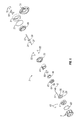
- FIG. 5 is an exploded view of the electro-mechanical lock bezel assembly
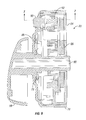
- FIG. 6 is a side cross-sectional view of the electro-mechanical lock bezel assembly
- FIG. 7 is a perspective view of the turnpiece assembly
- FIG. 8 is a perspective exploded view of the turnpiece assembly.
- FIG. 9 is a side cross-sectional view of the turnpiece assembly.
- FIG. 1 A perspective view of an electro-mechanical lock bezel assembly component 2 is shown in FIG. 1 .
- Assembly component 2 includes a keypad assembly 4 fitted within a rotatable bezel 6 adjacent a base 8 configured to fit against a door and cover a through bore 10 .
- Keypad 4 is configured to receive a combination code in order to activate a mechanism to unlock the door.
- assembly 2 Upon receipt of a proper code, assembly 2 activates so bezel 6 can be rotated to engage and rotate torque blade 12 which throws the latch to either locked or unlocked position. It is appreciated in this embodiment that bezel 6 may rotate with respect to base 8 .
- Cable ribbon 14 and connector 16 are configured to extend through bore 10 and connect to a battery case 86 in turnpiece assembly 20 located on the interior portion of door 22 . (See, also, FIGS. 8 and 9 .) Cable ribbon 14 is supported by a support 18 so as not to interfere with any of the backset assembly components that move the latch or bolt (not shown).
- FIG. 2 A cross-sectional perspective view of assembly 2 is shown in FIG. 2 .
- This view shows keypad assembly 4 , bezel 6 , and base 8 as discussed with respect to FIG. 1 .
- motor 24 which is in communication with a PCB board 26 that receives power through cable ribbon 14 .
- PCB board 26 determines if a proper combination is entered into keypad 4 and, if so, directs a signal to motor 24 to cause it to rotate.
- a drive rod 28 is attached to motor 24 and rotates as motor 24 rotates.
- Pin 30 extends essentially transversely to drive rod 28 and rotates therewith.
- Spring 32 is wound around drive rod 28 .
- a second spring 33 extends from flower 34 up into a torque-driver housing 36 .
- Pin 32 extends from drive rod 28 and acts as a cam follower by engaging the coil wire of spring 30 . This has the effect of compressing or extending spring 32 in one direction or another along the longitudinal length of drive rod 28 .
- a carriage 68 moves back and forth in directions 38 and 40 , as spring 32 expands and compresses.
- Flower 34 is engaged by carriage 68 so that as pin 30 extends or retracts spring 32 in either direction 38 or 40 , flower 34 is likewise pulled or pushed in directions 38 and 40 .
- Second spring 33 is in compression so it is configured to bias flower 34 in direction 38 .
- FIG. 3 A perspective view of electro-mechanical lock bezel assembly component 2 , attached to door 22 and extending through bore 10 to turnpiece assembly 20 , is shown in FIG. 3 .
- assembly 2 is coupled to a deadbolt 52 which extends through base plate 54 and edge 56 of door 22 .
- deadbolt 52 is extended (i.e., in the locked position) assembly 2 will not allow deadbolt 52 to retract (unless a proper code is entered).
- flower 34 is not engaged to both housing 36 and gear 48 , so either no code or improper code has been entered into keypad assembly 4 .
- motor 24 rotates drive rod 28 causing spring 32 and carriage 68 (see, also, FIG.
- turnpiece assembly 20 may include a knob 58 that is also engageable with torque blade 12 . As knob 58 rotates deadbolt 52 extends and retracts via conventional means.
- FIG. 4 Another perspective view of electro-mechanical lock bezel assembly component 2 coupled to door 22 and turnpiece assembly 20 is shown in FIG. 4 .
- This view differs from the view in FIG. 3 in that here deadbolt 52 is retracted into door 22 about flush with base plate 54 , indicating an unlocked position.
- a correct code was entered into keypad assembly 4 , which caused motor 24 to activate and rotate drive rod 28 to move carriage 68 (see, also, FIG. 5 ) so that flower 34 will be drawn from its location solely inside housing 36 in direction 38 and positions between both housing 36 and gear 48 .
- flower 34 straddles both housing 36 and gear 48 , a mechanical connection is created so that rotating bezel 6 rotates torque blade 12 which extends or retracts deadbolt 52 .
- FIG. 5 An exploded view of electro-mechanical lock bezel assembly component 2 is shown in FIG. 5 .
- the components include bezel 6 , bezel lip ring 60 , fasteners 62 , keypad 4 , PCB board 26 with ribbon cable 14 , connector 6 , motor 24 , torque blade 12 , a motor skirt 64 , motor plate 66 , gear 48 , carriage 68 , body 44 , gear portion 70 , fasteners 50 , spring 32 , flower 34 , torque-driver housing 36 , torque blade 12 , cover base 46 , bezel lip ring 72 , base 8 , optional square base 74 , support 18 , and fasteners 76 .
- fasteners 76 attach support 18 to body 44 .
- FIG. 6 A side cross-sectional view of electro-mechanical lock bezel assembly component 2 is shown in FIG. 6 . This view assists demonstrating how the components are assembled together.
- Torque blade 12 is shown attached to torque-driver housing 36 via pin 42 .
- Connector 16 is attached to ribbon cable 14 and itself is attached to PCB board 26 .
- Support 18 is attached to body 44 along with base 8 which is also located adjacent bezel 6 .
- Body 44 is located inside assembly 2 adjacent gear 48 . It is appreciated that gear 48 and gear portion 70 are meshed together.
- Gear portion 70 is coupled to bezel 6 via fasteners 50 .
- Lip rings 72 and 60 keep contaminants from getting into assembly 2 via seams between bezel 6 /base 8 and bezel 6 /keypad assembly 4 , respectively.
- Motor plate 66 shrouds motor 24 as shown.
- FIG. 7 A perspective view of turnpiece assembly 20 is shown in FIG. 7 .
- This view shows knob 58 extending from rose 78 .
- Button 80 extends from rose 78 as well.
- Fasteners 82 are also shown in this view.
- FIG. 8 A perspective exploded view of turnpiece assembly 20 is shown in FIG. 8 .
- This view includes plate 84 ; battery case 86 ; button 80 ; vibration dampening pads 88 ; rose 78 ; knob 58 ; and fasteners 82 .
- FIG. 9 The side cross-sectional view of turnpiece assembly 20 is shown in FIG. 9 depicting how the components shown in FIG. 8 are fitted together.
- Knob 58 includes a bore 90 configured to receive torque blade 12 so that turning knob 58 will also move deadbolt 52 .
- Knob 58 is attached to rose 78 via clip 79 .
- Fitted in rose 78 is battery case 86 , vibration dampening pads 88 , and button 80 is capped by plate 84 . It is appreciated that battery case 86 is configured to store one or a plurality of batteries and connect to connector 16 to deliver power to PCB board 26 .
- button 80 may engage a switch mechanism 92 that may be part of battery case 86 , or adjacent battery case 86 , to send a signal through connector 16 , ribbon cable 14 , and PCB board 26 to activate motor 24 to either retract or extend deadbolt 52 .
- a switch mechanism 92 may be part of battery case 86 , or adjacent battery case 86 , to send a signal through connector 16 , ribbon cable 14 , and PCB board 26 to activate motor 24 to either retract or extend deadbolt 52 .
Abstract
Description
Claims (28)
Priority Applications (2)
| Application Number | Priority Date | Filing Date | Title |
|---|---|---|---|
| US14/205,891 US9487971B2 (en) | 2013-03-15 | 2014-03-12 | Electro-mechanical locks with bezel turning function |
| US15/345,476 US10174523B2 (en) | 2013-03-15 | 2016-11-07 | Electro-mechanical locks with bezel turning function |
Applications Claiming Priority (2)
| Application Number | Priority Date | Filing Date | Title |
|---|---|---|---|
| US201361788410P | 2013-03-15 | 2013-03-15 | |
| US14/205,891 US9487971B2 (en) | 2013-03-15 | 2014-03-12 | Electro-mechanical locks with bezel turning function |
Related Child Applications (1)
| Application Number | Title | Priority Date | Filing Date |
|---|---|---|---|
| US15/345,476 Continuation US10174523B2 (en) | 2013-03-15 | 2016-11-07 | Electro-mechanical locks with bezel turning function |
Publications (2)
| Publication Number | Publication Date |
|---|---|
| US20140260451A1 US20140260451A1 (en) | 2014-09-18 |
| US9487971B2 true US9487971B2 (en) | 2016-11-08 |
Family
ID=50631005
Family Applications (2)
| Application Number | Title | Priority Date | Filing Date |
|---|---|---|---|
| US14/205,891 Active 2034-11-21 US9487971B2 (en) | 2013-03-15 | 2014-03-12 | Electro-mechanical locks with bezel turning function |
| US15/345,476 Active US10174523B2 (en) | 2013-03-15 | 2016-11-07 | Electro-mechanical locks with bezel turning function |
Family Applications After (1)
| Application Number | Title | Priority Date | Filing Date |
|---|---|---|---|
| US15/345,476 Active US10174523B2 (en) | 2013-03-15 | 2016-11-07 | Electro-mechanical locks with bezel turning function |
Country Status (3)
| Country | Link |
|---|---|
| US (2) | US9487971B2 (en) |
| CA (1) | CA2903811A1 (en) |
| WO (1) | WO2014151024A1 (en) |
Cited By (18)
| Publication number | Priority date | Publication date | Assignee | Title |
|---|---|---|---|---|
| US20160312496A1 (en) * | 2015-04-22 | 2016-10-27 | Lowe & Fletcher Limited | Locking device |
| CN107060493A (en) * | 2017-04-01 | 2017-08-18 | 重庆坤秀门窗有限公司 | Door handle with spinfunction |
| US20170284131A1 (en) * | 2016-04-01 | 2017-10-05 | Spectrum Brands, Inc. | Deadbolt touch panel for keyless entry |
| US10174523B2 (en) * | 2013-03-15 | 2019-01-08 | Spectrum Brands, Inc. | Electro-mechanical locks with bezel turning function |
| US10190337B2 (en) * | 2014-04-29 | 2019-01-29 | Nanjing Easthouse Electrical Co., Ltd. | Methods and systems of electronic and mechanical dual combination locks |
| US10508473B2 (en) * | 2014-08-27 | 2019-12-17 | Mitteldeutsche Tresorbau Gmbh | Compact operating unit for a safe lock |
| US10683677B1 (en) * | 2015-11-17 | 2020-06-16 | Otto Llc | Intelligent door lock system for use with a door assembly |
| USD922850S1 (en) * | 2020-03-20 | 2021-06-22 | Zhongshan Hydi Arrow Lock Co., Ltd | Door lock |
| USD923453S1 (en) * | 2020-03-20 | 2021-06-29 | Zhongshan Hydi Arrow Lock Co., Ltd | Door lock |
| USD923455S1 (en) * | 2020-03-20 | 2021-06-29 | Zhongshan Hydi Arrow Lock Co., Ltd | Door lock |
| USD923454S1 (en) * | 2020-03-20 | 2021-06-29 | Zhongshan Hydi Arrow Lock Co., Ltd | Door lock |
| USD935301S1 (en) * | 2020-03-20 | 2021-11-09 | Feifei CHEN | Door lock |
| USD935300S1 (en) * | 2020-03-20 | 2021-11-09 | Feifei CHEN | Door lock |
| USD965407S1 (en) * | 2019-04-05 | 2022-10-04 | Dormakaba Usa Inc | Knob |
| US11560736B2 (en) | 2020-03-04 | 2023-01-24 | Endura Products, Llc | Method for operating a door and components related to the same |
| US11639617B1 (en) | 2019-04-03 | 2023-05-02 | The Chamberlain Group Llc | Access control system and method |
| US20230268952A1 (en) * | 2022-02-23 | 2023-08-24 | Schlage Lock Company Llc | Door hardware cover |
| US11739564B2 (en) | 2020-03-04 | 2023-08-29 | Endura Products, Llc | Method for operating a door and components related to the same |
Families Citing this family (13)
| Publication number | Priority date | Publication date | Assignee | Title |
|---|---|---|---|---|
| US9562370B2 (en) | 2014-11-21 | 2017-02-07 | Schlage Lock Company Llc | Electromechanical lockset |
| WO2017006171A2 (en) * | 2015-07-06 | 2017-01-12 | Acsys Ip Holding Inc. | Systems and methods for secure lock systems with redundant access control |
| US10407942B2 (en) * | 2015-08-13 | 2019-09-10 | Spectrum Brands, Inc. | Low profile deadbolt |
| DE102016217549B4 (en) | 2016-09-14 | 2018-08-16 | AstraDirect Leasing & Service GmbH | combination lock |
| US10267063B2 (en) * | 2016-12-19 | 2019-04-23 | I-Tek Metal Mfg. Co., Ltd. | Electric door lock |
| TWM543909U (en) * | 2016-12-19 | 2017-06-21 | I-Tek Metal Manufacturing Co Ltd | Modularized electronic door lock |
| RU2735205C1 (en) | 2017-05-31 | 2020-10-28 | Артур ЛИТВИНСКИ | Driving device for lock unlocking and locking |
| USD839074S1 (en) * | 2017-08-14 | 2019-01-29 | Fath, Inc. | Gravity latch |
| KR101899127B1 (en) * | 2018-05-28 | 2018-10-04 | (주)필리아테크놀러지 | Digital door lock assembly |
| RU2681183C1 (en) * | 2018-06-29 | 2019-03-04 | Михаил Юрьевич Рылеев | Leaf handle |
| EP3628803B1 (en) * | 2018-09-26 | 2021-09-15 | RCO Security AB | Lock system for door knob |
| US11933092B2 (en) | 2019-08-13 | 2024-03-19 | SimpliSafe, Inc. | Mounting assembly for door lock |
| CN110965860A (en) * | 2019-12-20 | 2020-04-07 | 歌尔科技有限公司 | Intelligent lock |
Citations (96)
| Publication number | Priority date | Publication date | Assignee | Title |
|---|---|---|---|---|
| US2942907A (en) | 1957-03-25 | 1960-06-28 | Westinghouse Electric Corp | Magnetic latching mechanism |
| US3529454A (en) | 1968-01-31 | 1970-09-22 | Unican Security Systems | Combination lock controlled electrical instrumentality |
| US3733863A (en) | 1971-09-27 | 1973-05-22 | E Toepfer | Lock cylinder mechanism |
| US4148092A (en) | 1977-08-04 | 1979-04-03 | Ricky Martin | Electronic combination door lock with dead bolt sensing means |
| US4270781A (en) | 1979-02-28 | 1981-06-02 | Futaba Kinzoku Kogyo Kabushiki Kaisha | Opening and closing apparatus for doors and the like |
| US4640110A (en) | 1985-09-16 | 1987-02-03 | Ilco Unican Corp. | Automatic delay relocking device |
| US4656850A (en) | 1983-12-19 | 1987-04-14 | Miwa Lock Mfg. Co., Ltd. | Electric lock |
| US4736970A (en) | 1987-03-09 | 1988-04-12 | Mcgourty Thomas K | Electrically controlled door lock |
| US4770012A (en) | 1978-07-17 | 1988-09-13 | Intelock Corporation | Electronic digital combination lock |
| US4854143A (en) | 1987-08-07 | 1989-08-08 | Intelock Corporation | Bolt assembly and method |
| US4893704A (en) | 1989-03-27 | 1990-01-16 | General Motors Corporation | Power door lock actuator |
| US4901545A (en) * | 1987-12-28 | 1990-02-20 | Rising Star Technologies (A Partnership) | Self-contained electromechanical locking device |
| FR2653780A1 (en) | 1989-10-26 | 1991-05-03 | Elf Aquitaine | BASE ADDITIVE FOR LUBRICATING OILS CONTAINING A COPPER DERIVATIVE OR A COPPER AND BORON DERIVATIVE, METHOD FOR PREPARING SAME AND COMPOSITIONS CONTAINING SAID ADDITIVE. |
| US5040652A (en) | 1988-05-12 | 1991-08-20 | Ilco Unican Inc. | Cylindrical and permutation lock arrangements with clutch |
| US5052205A (en) | 1990-08-17 | 1991-10-01 | Julio Poli | Lock cylinder having a slide plate with one or more rows of pin tumblers and key therefor |
| US5083122A (en) | 1989-02-21 | 1992-01-21 | Osi Security Devices | Programmable individualized security system for door locks |
| US5121618A (en) | 1991-07-25 | 1992-06-16 | Rita Scott | Attachment for transforming lock cylinders into interchangeable cores |
| US5228730A (en) | 1992-09-02 | 1993-07-20 | Security People, Inc. | Apparatus for converting mechanical locks to operate electrically using momentary power |
| US5440909A (en) | 1993-06-29 | 1995-08-15 | The Highfield Mfg. Company | Lock and key shell assembly |
| US5474348A (en) | 1993-08-24 | 1995-12-12 | Best Lock Corporation | Motorized actuator for mortise lockset |
| US5473922A (en) | 1993-12-13 | 1995-12-12 | Sargent & Greenleaf, Inc. | Motorized electronic lock |
| US5475996A (en) | 1994-08-29 | 1995-12-19 | Chen; Tsun-Hsing | Electromagnetic door lock |
| US5609051A (en) | 1995-08-16 | 1997-03-11 | Donaldson; Edward M. | Keyless entry system for replacement of existing key locks |
| US5640863A (en) | 1995-09-06 | 1997-06-24 | Harrow Products, Inc. | Clutch mechanism for door lock system |
| US5709114A (en) | 1994-11-21 | 1998-01-20 | Mas-Hamilton Group | Keypad entry electronic combination lock with self-generated combination |
| US5712626A (en) | 1991-09-19 | 1998-01-27 | Master Lock Company | Remotely-operated self-contained electronic lock security system assembly |
| USD390446S (en) | 1997-01-31 | 1998-02-10 | La Gard, Inc. | Input dial for electronic lock |
| US5782118A (en) | 1996-07-16 | 1998-07-21 | Schlage Lock Company | Lockset with motorized system for locking and unlocking |
| US5857365A (en) | 1997-05-02 | 1999-01-12 | Emhart Inc. | Electronically operated lock |
| US5873276A (en) | 1994-11-21 | 1999-02-23 | Mas-Hamilton Group | Keypad entry electronic combination lock with self-generated combination |
| US5876073A (en) | 1997-05-05 | 1999-03-02 | Geringer; Arthur | Electrically operable door locking apparatus and method for operating the same |
| US5887467A (en) | 1994-03-30 | 1999-03-30 | U-Code, Inc. | Pawl & solenoid locking mechanism |
| US5894277A (en) | 1996-03-12 | 1999-04-13 | Security People, Inc. | Programmable digital electronic lock |
| US5933086A (en) | 1991-09-19 | 1999-08-03 | Schlage Lock Company | Remotely-operated self-contained electronic lock security system assembly |
| US5970759A (en) | 1995-07-19 | 1999-10-26 | Trilk; Hartmut | Changeover device for a door or window fitting |
| US6016677A (en) | 1998-01-02 | 2000-01-25 | Sargent & Greenleaf, Inc. | Dead bolt combination lock and push-pull lock, each with integrated re-locking features, lock with auxiliary security features, and lock keypad with tamper detection and response features |
| US6076383A (en) * | 1996-12-19 | 2000-06-20 | Mas-Hamilton Group, Inc. | Emitter and power drive system for an electronic lock |
| US6098433A (en) | 1998-04-02 | 2000-08-08 | American Security Products Company | Lock for safes and other security devices |
| US6125673A (en) | 1998-04-29 | 2000-10-03 | Trimel Securities Pty Ltd. | Electronic cylinder lock and computer security system |
| USD438447S1 (en) | 2000-04-06 | 2001-03-06 | Masco Corporation | Lock keypad |
| US6264256B1 (en) | 1998-07-31 | 2001-07-24 | Hewi Heinrich Wilke Gmbh | Closing system |
| US6286347B1 (en) | 1999-08-09 | 2001-09-11 | Harrow Products, Inc. | Clutch mechanism with moveable injector retainer wall for door lock system |
| US6298699B1 (en) | 1994-03-30 | 2001-10-09 | U-Code, Inc. | Electronic input and dial entry lock |
| US6318137B1 (en) | 1998-04-08 | 2001-11-20 | David Chaum | Electronic lock that can learn to recognize any ordinary key |
| US6345522B1 (en) | 1998-08-12 | 2002-02-12 | Star Lock Systems, Inc. | Electro-mechanical latching apparatus |
| US6378344B1 (en) | 2000-09-18 | 2002-04-30 | Klaus W. Gartner | Combination lock handle |
| US6442983B1 (en) | 1997-03-05 | 2002-09-03 | Michael Reed Thomas | Digital electronic lock |
| USD464862S1 (en) | 2000-12-29 | 2002-10-29 | Sarges Younani | Solar powered illuminated door knob |
| US6619085B1 (en) | 2002-09-12 | 2003-09-16 | Hui-Hua Hsieh | Remote-controlled lock |
| US6622534B1 (en) | 1997-02-10 | 2003-09-23 | Lockmasters, Inc. | Dead bolt system having multiple security features |
| US6655180B2 (en) | 2001-07-31 | 2003-12-02 | Security People, Inc. | Locker lock with adjustable bolt |
| US6718808B2 (en) | 2002-06-06 | 2004-04-13 | Chin-Shen Yu | Tubular-type locking cylinder and dedicated key |
| US6845642B2 (en) | 1999-12-31 | 2005-01-25 | Escudos Kala Internacional S.L. | Clutch mechanism for electronic locks |
| US6876293B2 (en) | 1998-04-03 | 2005-04-05 | Harrow Products, Llc | Multiple access electronic lock system |
| US6895791B2 (en) | 2002-05-09 | 2005-05-24 | Onity, Inc. | Electronic lock system |
| US20050183480A1 (en) | 2002-08-19 | 2005-08-25 | Hingston Neil R. | Electric lock |
| US6935149B1 (en) | 2004-03-23 | 2005-08-30 | Fu Chang Peng | Electric door lock openable by key |
| US20060065027A1 (en) | 2004-09-29 | 2006-03-30 | U-Code, Inc. | Two-piece electronic lock door handle |
| US7051561B2 (en) | 1999-12-08 | 2006-05-30 | Computerized Security Systems, Inc. | Electronic lock |
| US7091429B2 (en) | 2003-12-22 | 2006-08-15 | Yale Security Inc. | Privacy keypad |
| USD526883S1 (en) | 2005-01-12 | 2006-08-22 | Moen Incorporated | Knob |
| US7096697B2 (en) | 2002-05-16 | 2006-08-29 | Kym John Keightly | Electronic deadbolt lock arrangement |
| US7096698B2 (en) | 2003-03-11 | 2006-08-29 | Harrow Products Llc | Override assembly for door lock systems having a clutch mechanism |
| US7165428B2 (en) | 2002-01-26 | 2007-01-23 | Ison Limited | Lock |
| US7168276B2 (en) | 2003-10-10 | 2007-01-30 | Cisa S.P.A. | Electric lock with multiple-function spring |
| USD536948S1 (en) | 2005-12-21 | 2007-02-20 | Liberty Hardware Mfg. Corp. | Knob |
| USD537319S1 (en) | 2005-12-21 | 2007-02-27 | Liberty Hardware Mfg. Corp. | Knob |
| US7188495B2 (en) | 2003-10-10 | 2007-03-13 | Cisa S.P.A. | Electric lock with magnetic support of the coupling element |
| US20080078220A1 (en) | 2004-05-27 | 2008-04-03 | Unipass Co., Ltd. | Locking Apparatus Having a Latch Bolt Separated from Cylinder |
| US7424814B2 (en) | 1997-02-10 | 2008-09-16 | Lockmasters, Inc. | Dead bolt lock system having multiple security features |
| US20080296912A1 (en) * | 2007-05-29 | 2008-12-04 | Whitner Douglas E | Remote door access device |
| JP2009030426A (en) | 2007-06-25 | 2009-02-12 | Panasonic Electric Works Co Ltd | Electric lock |
| US20090133454A1 (en) | 2006-04-13 | 2009-05-28 | Schlage Lock Company | Electronic deadbolt lock |
| US7543469B1 (en) | 2008-04-07 | 2009-06-09 | Sun-Castle Global Precision Technology Co., Ltd. | Mechanism of electronic door lock |
| US20090211319A1 (en) | 2008-02-22 | 2009-08-27 | Mccormack Scott Alexander | Locks and inserts therefor |
| US7591157B2 (en) | 2003-10-16 | 2009-09-22 | Daz Lock Pty Ltd | Security lock arrangement |
| US20100011822A1 (en) * | 2008-07-15 | 2010-01-21 | Imedio Ocana Juan | Electromechanical cylinder for lock |
| US7698919B2 (en) | 2005-04-06 | 2010-04-20 | Gab-Sik Kim | Locking device |
| US20100126240A1 (en) | 2007-06-19 | 2010-05-27 | Evva Sicherheitstechnologie Gmbh | Device for locking a lock |
| US20100154494A1 (en) * | 2008-12-18 | 2010-06-24 | Keiden Sangyo Co., Ltd. | Connecting adaptor for electric cylinder corresponding to mortise lock |
| US20100257906A1 (en) | 2009-04-10 | 2010-10-14 | Birk Cliff Sorensen | Keypad lockset |
| USD631323S1 (en) | 2010-01-19 | 2011-01-25 | Master Lock Company Llc | Lock |
| US7918114B2 (en) | 2005-07-07 | 2011-04-05 | Harrow Products Llc | Electronic lock actuator with helical drive member |
| US20110079057A1 (en) | 2009-10-05 | 2011-04-07 | George Frolov | Electrically controlled door lock |
| US7963134B2 (en) | 2003-08-20 | 2011-06-21 | Master Lock Company Llc | Deadbolt lock |
| US7966854B2 (en) * | 2008-07-15 | 2011-06-28 | Salto Systems, S.L. | Clutch mechanism applicable to electromechanical cylinders for locks |
| US20110215597A1 (en) | 2010-03-04 | 2011-09-08 | Dag Trygve Weum | Motor mechanism |
| US8091392B2 (en) | 2008-09-05 | 2012-01-10 | Lock II, L.L.C. | High security lock |
| US20120198897A1 (en) | 2009-11-12 | 2012-08-09 | Pang-Cheng Lui | Driving device for an electric lock latch |
| US8276415B2 (en) | 2009-03-20 | 2012-10-02 | Knox Associates | Holding coil for electronic lock |
| WO2012177609A1 (en) | 2011-06-20 | 2012-12-27 | Newfrey Llc | Manually driven electronic deadbolt assembly with free-spinning bezel |
| US20130031940A1 (en) | 2011-08-02 | 2013-02-07 | Oscar Romero | Manually driven electronic deadbolt assembly with fixed turnpiece |
| US8375753B2 (en) * | 2007-02-08 | 2013-02-19 | Knock N'lock Ltd. | Solenoid-operated electromechanical lock |
| US8689594B2 (en) * | 2010-03-12 | 2014-04-08 | Tuncay Erhan Yanar | Electrical cylinder lock |
| US20150096341A1 (en) * | 2013-10-07 | 2015-04-09 | Poly-Care Aps | Motorised Door Lock Actuator |
| US9024759B2 (en) * | 2013-03-15 | 2015-05-05 | Kwikset Corporation | Wireless lockset with integrated antenna, touch activation, and light communication method |
Family Cites Families (2)
| Publication number | Priority date | Publication date | Assignee | Title |
|---|---|---|---|---|
| EP0924298A1 (en) | 1997-12-18 | 1999-06-23 | Stichting Instituut voor Dierhouderij en Diergezondheid (ID-DLO) | Protein expression in baculovirus vector expression systems |
| CA2903811A1 (en) * | 2013-03-15 | 2014-09-25 | Spectrum Brands, Inc. | Electro-mechanical locks with bezel turning function |
-
2014
- 2014-03-12 CA CA2903811A patent/CA2903811A1/en not_active Abandoned
- 2014-03-12 WO PCT/US2014/024787 patent/WO2014151024A1/en active Application Filing
- 2014-03-12 US US14/205,891 patent/US9487971B2/en active Active
-
2016
- 2016-11-07 US US15/345,476 patent/US10174523B2/en active Active
Patent Citations (100)
| Publication number | Priority date | Publication date | Assignee | Title |
|---|---|---|---|---|
| US2942907A (en) | 1957-03-25 | 1960-06-28 | Westinghouse Electric Corp | Magnetic latching mechanism |
| US3529454A (en) | 1968-01-31 | 1970-09-22 | Unican Security Systems | Combination lock controlled electrical instrumentality |
| US3733863A (en) | 1971-09-27 | 1973-05-22 | E Toepfer | Lock cylinder mechanism |
| US4148092A (en) | 1977-08-04 | 1979-04-03 | Ricky Martin | Electronic combination door lock with dead bolt sensing means |
| US4770012A (en) | 1978-07-17 | 1988-09-13 | Intelock Corporation | Electronic digital combination lock |
| US4270781A (en) | 1979-02-28 | 1981-06-02 | Futaba Kinzoku Kogyo Kabushiki Kaisha | Opening and closing apparatus for doors and the like |
| US4656850A (en) | 1983-12-19 | 1987-04-14 | Miwa Lock Mfg. Co., Ltd. | Electric lock |
| US4640110A (en) | 1985-09-16 | 1987-02-03 | Ilco Unican Corp. | Automatic delay relocking device |
| US4736970A (en) | 1987-03-09 | 1988-04-12 | Mcgourty Thomas K | Electrically controlled door lock |
| US4854143A (en) | 1987-08-07 | 1989-08-08 | Intelock Corporation | Bolt assembly and method |
| US4901545A (en) * | 1987-12-28 | 1990-02-20 | Rising Star Technologies (A Partnership) | Self-contained electromechanical locking device |
| US5040652A (en) | 1988-05-12 | 1991-08-20 | Ilco Unican Inc. | Cylindrical and permutation lock arrangements with clutch |
| US5083122A (en) | 1989-02-21 | 1992-01-21 | Osi Security Devices | Programmable individualized security system for door locks |
| US4893704A (en) | 1989-03-27 | 1990-01-16 | General Motors Corporation | Power door lock actuator |
| FR2653780A1 (en) | 1989-10-26 | 1991-05-03 | Elf Aquitaine | BASE ADDITIVE FOR LUBRICATING OILS CONTAINING A COPPER DERIVATIVE OR A COPPER AND BORON DERIVATIVE, METHOD FOR PREPARING SAME AND COMPOSITIONS CONTAINING SAID ADDITIVE. |
| US5052205A (en) | 1990-08-17 | 1991-10-01 | Julio Poli | Lock cylinder having a slide plate with one or more rows of pin tumblers and key therefor |
| US5121618A (en) | 1991-07-25 | 1992-06-16 | Rita Scott | Attachment for transforming lock cylinders into interchangeable cores |
| US5933086A (en) | 1991-09-19 | 1999-08-03 | Schlage Lock Company | Remotely-operated self-contained electronic lock security system assembly |
| US6107934A (en) | 1991-09-19 | 2000-08-22 | Schlage Lock Company | Remotely operated self-contained electronic lock security system assembly |
| US5712626A (en) | 1991-09-19 | 1998-01-27 | Master Lock Company | Remotely-operated self-contained electronic lock security system assembly |
| US6297725B1 (en) | 1991-09-19 | 2001-10-02 | Schlage Lock Company | Remotely-operated self-contained electronic lock security system assembly |
| US5228730A (en) | 1992-09-02 | 1993-07-20 | Security People, Inc. | Apparatus for converting mechanical locks to operate electrically using momentary power |
| US5440909A (en) | 1993-06-29 | 1995-08-15 | The Highfield Mfg. Company | Lock and key shell assembly |
| US5474348A (en) | 1993-08-24 | 1995-12-12 | Best Lock Corporation | Motorized actuator for mortise lockset |
| US5473922A (en) | 1993-12-13 | 1995-12-12 | Sargent & Greenleaf, Inc. | Motorized electronic lock |
| US6298699B1 (en) | 1994-03-30 | 2001-10-09 | U-Code, Inc. | Electronic input and dial entry lock |
| US5887467A (en) | 1994-03-30 | 1999-03-30 | U-Code, Inc. | Pawl & solenoid locking mechanism |
| US5475996A (en) | 1994-08-29 | 1995-12-19 | Chen; Tsun-Hsing | Electromagnetic door lock |
| US5873276A (en) | 1994-11-21 | 1999-02-23 | Mas-Hamilton Group | Keypad entry electronic combination lock with self-generated combination |
| US5709114A (en) | 1994-11-21 | 1998-01-20 | Mas-Hamilton Group | Keypad entry electronic combination lock with self-generated combination |
| US5970759A (en) | 1995-07-19 | 1999-10-26 | Trilk; Hartmut | Changeover device for a door or window fitting |
| US5609051A (en) | 1995-08-16 | 1997-03-11 | Donaldson; Edward M. | Keyless entry system for replacement of existing key locks |
| US5640863A (en) | 1995-09-06 | 1997-06-24 | Harrow Products, Inc. | Clutch mechanism for door lock system |
| US5894277A (en) | 1996-03-12 | 1999-04-13 | Security People, Inc. | Programmable digital electronic lock |
| US5782118A (en) | 1996-07-16 | 1998-07-21 | Schlage Lock Company | Lockset with motorized system for locking and unlocking |
| US6038896A (en) | 1996-07-16 | 2000-03-21 | Schlage Lock Company | Lockset with motorized system for locking and unlocking |
| US6076383A (en) * | 1996-12-19 | 2000-06-20 | Mas-Hamilton Group, Inc. | Emitter and power drive system for an electronic lock |
| USD390446S (en) | 1997-01-31 | 1998-02-10 | La Gard, Inc. | Input dial for electronic lock |
| US6622534B1 (en) | 1997-02-10 | 2003-09-23 | Lockmasters, Inc. | Dead bolt system having multiple security features |
| US7424814B2 (en) | 1997-02-10 | 2008-09-16 | Lockmasters, Inc. | Dead bolt lock system having multiple security features |
| US6442983B1 (en) | 1997-03-05 | 2002-09-03 | Michael Reed Thomas | Digital electronic lock |
| US5857365A (en) | 1997-05-02 | 1999-01-12 | Emhart Inc. | Electronically operated lock |
| US5876073A (en) | 1997-05-05 | 1999-03-02 | Geringer; Arthur | Electrically operable door locking apparatus and method for operating the same |
| US6016677A (en) | 1998-01-02 | 2000-01-25 | Sargent & Greenleaf, Inc. | Dead bolt combination lock and push-pull lock, each with integrated re-locking features, lock with auxiliary security features, and lock keypad with tamper detection and response features |
| US6196037B1 (en) | 1998-01-02 | 2001-03-06 | Sargent & Greenleaf, Inc. | Lock system enabling user to lock door and extend lock bolt in a single action and push-pull lock with cushioning arrangement for protecting bolt drive components |
| US6098433A (en) | 1998-04-02 | 2000-08-08 | American Security Products Company | Lock for safes and other security devices |
| US6876293B2 (en) | 1998-04-03 | 2005-04-05 | Harrow Products, Llc | Multiple access electronic lock system |
| US6318137B1 (en) | 1998-04-08 | 2001-11-20 | David Chaum | Electronic lock that can learn to recognize any ordinary key |
| US6125673A (en) | 1998-04-29 | 2000-10-03 | Trimel Securities Pty Ltd. | Electronic cylinder lock and computer security system |
| US6264256B1 (en) | 1998-07-31 | 2001-07-24 | Hewi Heinrich Wilke Gmbh | Closing system |
| US6345522B1 (en) | 1998-08-12 | 2002-02-12 | Star Lock Systems, Inc. | Electro-mechanical latching apparatus |
| US6286347B1 (en) | 1999-08-09 | 2001-09-11 | Harrow Products, Inc. | Clutch mechanism with moveable injector retainer wall for door lock system |
| US7051561B2 (en) | 1999-12-08 | 2006-05-30 | Computerized Security Systems, Inc. | Electronic lock |
| US6845642B2 (en) | 1999-12-31 | 2005-01-25 | Escudos Kala Internacional S.L. | Clutch mechanism for electronic locks |
| USD438447S1 (en) | 2000-04-06 | 2001-03-06 | Masco Corporation | Lock keypad |
| US6378344B1 (en) | 2000-09-18 | 2002-04-30 | Klaus W. Gartner | Combination lock handle |
| USD464862S1 (en) | 2000-12-29 | 2002-10-29 | Sarges Younani | Solar powered illuminated door knob |
| US6655180B2 (en) | 2001-07-31 | 2003-12-02 | Security People, Inc. | Locker lock with adjustable bolt |
| US7165428B2 (en) | 2002-01-26 | 2007-01-23 | Ison Limited | Lock |
| US6895791B2 (en) | 2002-05-09 | 2005-05-24 | Onity, Inc. | Electronic lock system |
| US7096697B2 (en) | 2002-05-16 | 2006-08-29 | Kym John Keightly | Electronic deadbolt lock arrangement |
| US6718808B2 (en) | 2002-06-06 | 2004-04-13 | Chin-Shen Yu | Tubular-type locking cylinder and dedicated key |
| US20050183480A1 (en) | 2002-08-19 | 2005-08-25 | Hingston Neil R. | Electric lock |
| US6619085B1 (en) | 2002-09-12 | 2003-09-16 | Hui-Hua Hsieh | Remote-controlled lock |
| US7096698B2 (en) | 2003-03-11 | 2006-08-29 | Harrow Products Llc | Override assembly for door lock systems having a clutch mechanism |
| US7963134B2 (en) | 2003-08-20 | 2011-06-21 | Master Lock Company Llc | Deadbolt lock |
| US7168276B2 (en) | 2003-10-10 | 2007-01-30 | Cisa S.P.A. | Electric lock with multiple-function spring |
| US7188495B2 (en) | 2003-10-10 | 2007-03-13 | Cisa S.P.A. | Electric lock with magnetic support of the coupling element |
| US7591157B2 (en) | 2003-10-16 | 2009-09-22 | Daz Lock Pty Ltd | Security lock arrangement |
| US7091429B2 (en) | 2003-12-22 | 2006-08-15 | Yale Security Inc. | Privacy keypad |
| US6935149B1 (en) | 2004-03-23 | 2005-08-30 | Fu Chang Peng | Electric door lock openable by key |
| US20080078220A1 (en) | 2004-05-27 | 2008-04-03 | Unipass Co., Ltd. | Locking Apparatus Having a Latch Bolt Separated from Cylinder |
| US20060065027A1 (en) | 2004-09-29 | 2006-03-30 | U-Code, Inc. | Two-piece electronic lock door handle |
| USD526883S1 (en) | 2005-01-12 | 2006-08-22 | Moen Incorporated | Knob |
| US7698919B2 (en) | 2005-04-06 | 2010-04-20 | Gab-Sik Kim | Locking device |
| US7918114B2 (en) | 2005-07-07 | 2011-04-05 | Harrow Products Llc | Electronic lock actuator with helical drive member |
| USD536948S1 (en) | 2005-12-21 | 2007-02-20 | Liberty Hardware Mfg. Corp. | Knob |
| USD537319S1 (en) | 2005-12-21 | 2007-02-27 | Liberty Hardware Mfg. Corp. | Knob |
| US20090133454A1 (en) | 2006-04-13 | 2009-05-28 | Schlage Lock Company | Electronic deadbolt lock |
| US8375753B2 (en) * | 2007-02-08 | 2013-02-19 | Knock N'lock Ltd. | Solenoid-operated electromechanical lock |
| US20080296912A1 (en) * | 2007-05-29 | 2008-12-04 | Whitner Douglas E | Remote door access device |
| US20100126240A1 (en) | 2007-06-19 | 2010-05-27 | Evva Sicherheitstechnologie Gmbh | Device for locking a lock |
| JP2009030426A (en) | 2007-06-25 | 2009-02-12 | Panasonic Electric Works Co Ltd | Electric lock |
| US20090211319A1 (en) | 2008-02-22 | 2009-08-27 | Mccormack Scott Alexander | Locks and inserts therefor |
| US7543469B1 (en) | 2008-04-07 | 2009-06-09 | Sun-Castle Global Precision Technology Co., Ltd. | Mechanism of electronic door lock |
| US20100011822A1 (en) * | 2008-07-15 | 2010-01-21 | Imedio Ocana Juan | Electromechanical cylinder for lock |
| US7966854B2 (en) * | 2008-07-15 | 2011-06-28 | Salto Systems, S.L. | Clutch mechanism applicable to electromechanical cylinders for locks |
| US8091392B2 (en) | 2008-09-05 | 2012-01-10 | Lock II, L.L.C. | High security lock |
| US20100154494A1 (en) * | 2008-12-18 | 2010-06-24 | Keiden Sangyo Co., Ltd. | Connecting adaptor for electric cylinder corresponding to mortise lock |
| US8276415B2 (en) | 2009-03-20 | 2012-10-02 | Knox Associates | Holding coil for electronic lock |
| US20100257906A1 (en) | 2009-04-10 | 2010-10-14 | Birk Cliff Sorensen | Keypad lockset |
| US20110079057A1 (en) | 2009-10-05 | 2011-04-07 | George Frolov | Electrically controlled door lock |
| US20120198897A1 (en) | 2009-11-12 | 2012-08-09 | Pang-Cheng Lui | Driving device for an electric lock latch |
| USD631323S1 (en) | 2010-01-19 | 2011-01-25 | Master Lock Company Llc | Lock |
| US20110215597A1 (en) | 2010-03-04 | 2011-09-08 | Dag Trygve Weum | Motor mechanism |
| US8689594B2 (en) * | 2010-03-12 | 2014-04-08 | Tuncay Erhan Yanar | Electrical cylinder lock |
| WO2012177609A1 (en) | 2011-06-20 | 2012-12-27 | Newfrey Llc | Manually driven electronic deadbolt assembly with free-spinning bezel |
| US20130031940A1 (en) | 2011-08-02 | 2013-02-07 | Oscar Romero | Manually driven electronic deadbolt assembly with fixed turnpiece |
| US9024759B2 (en) * | 2013-03-15 | 2015-05-05 | Kwikset Corporation | Wireless lockset with integrated antenna, touch activation, and light communication method |
| US20150096341A1 (en) * | 2013-10-07 | 2015-04-09 | Poly-Care Aps | Motorised Door Lock Actuator |
Non-Patent Citations (3)
| Title |
|---|
| International Searching Authority; International Search Report; Jul. 10, 2014. |
| Schlage Installation Instructions. Manual (online). Schlage Lock Company, Mar. 23, 2009, (retried on Aug. 15, 2012), retrieved from the Internet: . |
| Schlage Installation Instructions. Manual (online). Schlage Lock Company, Mar. 23, 2009, (retried on Aug. 15, 2012), retrieved from the Internet: <URL: http://consumer.schlage.com/Project%20Documents/P515-858.pdf>. |
Cited By (21)
| Publication number | Priority date | Publication date | Assignee | Title |
|---|---|---|---|---|
| US10174523B2 (en) * | 2013-03-15 | 2019-01-08 | Spectrum Brands, Inc. | Electro-mechanical locks with bezel turning function |
| US10190337B2 (en) * | 2014-04-29 | 2019-01-29 | Nanjing Easthouse Electrical Co., Ltd. | Methods and systems of electronic and mechanical dual combination locks |
| US10508473B2 (en) * | 2014-08-27 | 2019-12-17 | Mitteldeutsche Tresorbau Gmbh | Compact operating unit for a safe lock |
| US20160312496A1 (en) * | 2015-04-22 | 2016-10-27 | Lowe & Fletcher Limited | Locking device |
| US9777511B2 (en) * | 2015-04-22 | 2017-10-03 | Lowe & Fletcher Limited | Locking device |
| US10683677B1 (en) * | 2015-11-17 | 2020-06-16 | Otto Llc | Intelligent door lock system for use with a door assembly |
| US20170284131A1 (en) * | 2016-04-01 | 2017-10-05 | Spectrum Brands, Inc. | Deadbolt touch panel for keyless entry |
| US10519694B2 (en) * | 2016-04-01 | 2019-12-31 | Spectrum Brands, Inc. | Deadbolt touch panel for keyless entry |
| CN107060493B (en) * | 2017-04-01 | 2018-10-16 | 重庆坤秀门窗有限公司 | door handle with rotation function |
| CN107060493A (en) * | 2017-04-01 | 2017-08-18 | 重庆坤秀门窗有限公司 | Door handle with spinfunction |
| US11639617B1 (en) | 2019-04-03 | 2023-05-02 | The Chamberlain Group Llc | Access control system and method |
| USD965407S1 (en) * | 2019-04-05 | 2022-10-04 | Dormakaba Usa Inc | Knob |
| US11739564B2 (en) | 2020-03-04 | 2023-08-29 | Endura Products, Llc | Method for operating a door and components related to the same |
| US11560736B2 (en) | 2020-03-04 | 2023-01-24 | Endura Products, Llc | Method for operating a door and components related to the same |
| USD922850S1 (en) * | 2020-03-20 | 2021-06-22 | Zhongshan Hydi Arrow Lock Co., Ltd | Door lock |
| USD935300S1 (en) * | 2020-03-20 | 2021-11-09 | Feifei CHEN | Door lock |
| USD935301S1 (en) * | 2020-03-20 | 2021-11-09 | Feifei CHEN | Door lock |
| USD923454S1 (en) * | 2020-03-20 | 2021-06-29 | Zhongshan Hydi Arrow Lock Co., Ltd | Door lock |
| USD923455S1 (en) * | 2020-03-20 | 2021-06-29 | Zhongshan Hydi Arrow Lock Co., Ltd | Door lock |
| USD923453S1 (en) * | 2020-03-20 | 2021-06-29 | Zhongshan Hydi Arrow Lock Co., Ltd | Door lock |
| US20230268952A1 (en) * | 2022-02-23 | 2023-08-24 | Schlage Lock Company Llc | Door hardware cover |
Also Published As
| Publication number | Publication date |
|---|---|
| WO2014151024A1 (en) | 2014-09-25 |
| US20140260451A1 (en) | 2014-09-18 |
| US10174523B2 (en) | 2019-01-08 |
| CA2903811A1 (en) | 2014-09-25 |
| US20170051534A1 (en) | 2017-02-23 |
Similar Documents
| Publication | Publication Date | Title |
|---|---|---|
| US10174523B2 (en) | Electro-mechanical locks with bezel turning function | |
| US9051761B2 (en) | Manually driven electronic deadbolt assembly with fixed turnpiece | |
| CN106996221B (en) | Redundant actuation locking device | |
| US5531086A (en) | Keyless entry deadbolt lock | |
| US7543469B1 (en) | Mechanism of electronic door lock | |
| US6286347B1 (en) | Clutch mechanism with moveable injector retainer wall for door lock system | |
| EP3400351B1 (en) | Electromechanical door lock actuation device | |
| US9181730B1 (en) | Driving structure of electronic lock | |
| CA2616807A1 (en) | Electronic security device | |
| US20070017265A1 (en) | Lock device | |
| US9273489B2 (en) | Lock assembly having motor inside interior operator handle | |
| GB2442387A (en) | Electronic lock actuator with helical drive member | |
| EP1738980A1 (en) | Locking system | |
| CN101351608A (en) | Security system for entrance barriers | |
| US9260887B2 (en) | Lock assembly | |
| DE102008018906B4 (en) | Lock cylinder arrangement | |
| GB201303014D0 (en) | Lock assembly | |
| US5460417A (en) | Tubular lock assembly | |
| US11834866B2 (en) | Flexible coupling for electronic deadbolt systems | |
| CN112262246A (en) | Electric drive mechanism for actuating a lock | |
| US9789852B2 (en) | Anti-theft device for a steering column and associated steering column | |
| CN101634202A (en) | Locking mechanism of locks | |
| WO2017142471A1 (en) | Electronic door lock operating device | |
| US10458149B2 (en) | Lock apparatus | |
| KR102302406B1 (en) | EXIT DEVICE DOGING WITH COMBINATION LOCK |
Legal Events
| Date | Code | Title | Description |
|---|---|---|---|
| AS | Assignment |
Owner name: KWIKSET CORPORATION, CALIFORNIA Free format text: ASSIGNMENT OF ASSIGNORS INTEREST;ASSIGNORS:QUACH, BYRON;FARAG, HANNA OSAMA;LIN, JAMES;SIGNING DATES FROM 20140320 TO 20140326;REEL/FRAME:032549/0397 |
|
| AS | Assignment |
Owner name: WELLS FARGO BANK, NATIONAL ASSOCIATION, GEORGIA Free format text: SECURITY INTEREST;ASSIGNORS:SPECTRUM BRANDS, INC.;UNITED PET GROUP, INC.;KWIKSET CORPORATION;AND OTHERS;REEL/FRAME:032874/0109 Effective date: 20140430 |
|
| AS | Assignment |
Owner name: APPLICA CONSUMER PRODUCTS, INC., A CORP. OF FLORIDA, FLORIDA Free format text: RELEASE BY SECURED PARTY;ASSIGNOR:WELLS FARGO BANK, NATIONAL ASSOCIATION, AS COLLATERAL TRUSTEE;REEL/FRAME:036102/0001 Effective date: 20150623 Owner name: SPECTRUM BRANDS, INC. AS SUCCESSOR IN INTEREST TO ROVCAL, INC., WISCONSIN Free format text: RELEASE BY SECURED PARTY;ASSIGNOR:WELLS FARGO BANK, NATIONAL ASSOCIATION, AS COLLATERAL TRUSTEE;REEL/FRAME:036102/0001 Effective date: 20150623 Owner name: SPECTRUM BRANDS, INC., A CORP. OF DELAWARE, WISCONSIN Free format text: RELEASE BY SECURED PARTY;ASSIGNOR:WELLS FARGO BANK, NATIONAL ASSOCIATION, AS COLLATERAL TRUSTEE;REEL/FRAME:036102/0001 Effective date: 20150623 Owner name: TETRA HOLDING (US), INC., A CORP. OF DELAWARE, VIRGINIA Free format text: RELEASE BY SECURED PARTY;ASSIGNOR:WELLS FARGO BANK, NATIONAL ASSOCIATION, AS COLLATERAL TRUSTEE;REEL/FRAME:036102/0001 Effective date: 20150623 Owner name: UNITED INDUSTRIES CORPORATION AS SUCCESSOR IN INTEREST TO LIQUID HOLDING COMPANY, INC., MISSOURI Free format text: RELEASE BY SECURED PARTY;ASSIGNOR:WELLS FARGO BANK, NATIONAL ASSOCIATION, AS COLLATERAL TRUSTEE;REEL/FRAME:036102/0001 Effective date: 20150623 Owner name: UNITED PET GROUP, INC., A CORP. OF DELAWARE, WISCONSIN Free format text: RELEASE BY SECURED PARTY;ASSIGNOR:WELLS FARGO BANK, NATIONAL ASSOCIATION, AS COLLATERAL TRUSTEE;REEL/FRAME:036102/0001 Effective date: 20150623 Owner name: UNITED INDUSTRIES CORPORATION AS SUCCESSOR IN INTE Free format text: RELEASE BY SECURED PARTY;ASSIGNOR:WELLS FARGO BANK, NATIONAL ASSOCIATION, AS COLLATERAL TRUSTEE;REEL/FRAME:036102/0001 Effective date: 20150623 Owner name: RUSSELL HOBBS, INC., A CORP. OF DELAWARE, ILLINOIS Free format text: RELEASE BY SECURED PARTY;ASSIGNOR:WELLS FARGO BANK, NATIONAL ASSOCIATION, AS COLLATERAL TRUSTEE;REEL/FRAME:036102/0001 Effective date: 20150623 Owner name: APPLICA CONSUMER PRODUCTS, INC., FLORIDA Free format text: RELEASE BY SECURED PARTY;ASSIGNOR:WELLS FARGO BANK, NATIONAL ASSOCIATION, AS COLLATERAL TRUSTEE;REEL/FRAME:036102/0001 Effective date: 20150623 Owner name: ROVCAL, INC., WISCONSIN Free format text: RELEASE BY SECURED PARTY;ASSIGNOR:WELLS FARGO BANK, NATIONAL ASSOCIATION, AS COLLATERAL TRUSTEE;REEL/FRAME:036102/0001 Effective date: 20150623 Owner name: UNITED PET GROUP, INC., A CORP. OF DELAWARE, WISCO Free format text: RELEASE BY SECURED PARTY;ASSIGNOR:WELLS FARGO BANK, NATIONAL ASSOCIATION, AS COLLATERAL TRUSTEE;REEL/FRAME:036102/0001 Effective date: 20150623 Owner name: PRICE PFISTER, INC., CALIFORNIA Free format text: RELEASE BY SECURED PARTY;ASSIGNOR:WELLS FARGO BANK, NATIONAL ASSOCIATION, AS COLLATERAL TRUSTEE;REEL/FRAME:036102/0001 Effective date: 20150623 Owner name: NATIONAL MANUFACTURING CO., CALIFORNIA Free format text: RELEASE BY SECURED PARTY;ASSIGNOR:WELLS FARGO BANK, NATIONAL ASSOCIATION, AS COLLATERAL TRUSTEE;REEL/FRAME:036102/0001 Effective date: 20150623 Owner name: UNITED PET GROUP, INC., WISCONSIN Free format text: RELEASE BY SECURED PARTY;ASSIGNOR:WELLS FARGO BANK, NATIONAL ASSOCIATION, AS COLLATERAL TRUSTEE;REEL/FRAME:036102/0001 Effective date: 20150623 Owner name: KWIKSET CORPORATION, CALIFORNIA Free format text: RELEASE BY SECURED PARTY;ASSIGNOR:WELLS FARGO BANK, NATIONAL ASSOCIATION, AS COLLATERAL TRUSTEE;REEL/FRAME:036102/0001 Effective date: 20150623 Owner name: SPECTRUM BRANDS, INC., A CORP. OF DELAWARE, WISCON Free format text: RELEASE BY SECURED PARTY;ASSIGNOR:WELLS FARGO BANK, NATIONAL ASSOCIATION, AS COLLATERAL TRUSTEE;REEL/FRAME:036102/0001 Effective date: 20150623 Owner name: SALIX ANIMAL HEALTH, LLC, FLORIDA Free format text: RELEASE BY SECURED PARTY;ASSIGNOR:WELLS FARGO BANK, NATIONAL ASSOCIATION, AS COLLATERAL TRUSTEE;REEL/FRAME:036102/0001 Effective date: 20150623 Owner name: TETRA HOLDINGS (US), INC., VIRGINIA Free format text: RELEASE BY SECURED PARTY;ASSIGNOR:WELLS FARGO BANK, NATIONAL ASSOCIATION, AS COLLATERAL TRUSTEE;REEL/FRAME:036102/0001 Effective date: 20150623 Owner name: TELL MANUFACTURING, INC., PENNSYLVANIA Free format text: RELEASE BY SECURED PARTY;ASSIGNOR:WELLS FARGO BANK, NATIONAL ASSOCIATION, AS COLLATERAL TRUSTEE;REEL/FRAME:036102/0001 Effective date: 20150623 Owner name: APPLICA CONSUMER PRODUCTS, INC., A CORP. OF FLORID Free format text: RELEASE BY SECURED PARTY;ASSIGNOR:WELLS FARGO BANK, NATIONAL ASSOCIATION, AS COLLATERAL TRUSTEE;REEL/FRAME:036102/0001 Effective date: 20150623 Owner name: TETRA HOLDING (US), INC., A CORP. OF DELAWARE, VIR Free format text: RELEASE BY SECURED PARTY;ASSIGNOR:WELLS FARGO BANK, NATIONAL ASSOCIATION, AS COLLATERAL TRUSTEE;REEL/FRAME:036102/0001 Effective date: 20150623 Owner name: SPECTRUM BRANDS, INC. AS SUCCESSOR IN INTEREST TO Free format text: RELEASE BY SECURED PARTY;ASSIGNOR:WELLS FARGO BANK, NATIONAL ASSOCIATION, AS COLLATERAL TRUSTEE;REEL/FRAME:036102/0001 Effective date: 20150623 Owner name: UNITED INDUSTRIES CORPORATION, MISSOURI Free format text: RELEASE BY SECURED PARTY;ASSIGNOR:WELLS FARGO BANK, NATIONAL ASSOCIATION, AS COLLATERAL TRUSTEE;REEL/FRAME:036102/0001 Effective date: 20150623 Owner name: SEED RESOURCES, L.L.C., MICHIGAN Free format text: RELEASE BY SECURED PARTY;ASSIGNOR:WELLS FARGO BANK, NATIONAL ASSOCIATION, AS COLLATERAL TRUSTEE;REEL/FRAME:036102/0001 Effective date: 20150623 Owner name: ROVCAL, INC., A CORP. OF CALIFORNIA, WISCONSIN Free format text: RELEASE BY SECURED PARTY;ASSIGNOR:WELLS FARGO BANK, NATIONAL ASSOCIATION, AS COLLATERAL TRUSTEE;REEL/FRAME:036102/0001 Effective date: 20150623 Owner name: ROV HOLDING, INC., A CORP. OF DELAWARE, DELAWARE Free format text: RELEASE BY SECURED PARTY;ASSIGNOR:WELLS FARGO BANK, NATIONAL ASSOCIATION, AS COLLATERAL TRUSTEE;REEL/FRAME:036102/0001 Effective date: 20150623 Owner name: LIQUID HOLDING COMPANY, INC., PENNSYLVANIA Free format text: RELEASE BY SECURED PARTY;ASSIGNOR:WELLS FARGO BANK, NATIONAL ASSOCIATION, AS COLLATERAL TRUSTEE;REEL/FRAME:036102/0001 Effective date: 20150623 Owner name: SPECTRUM BRANDS, INC., WISCONSIN Free format text: RELEASE BY SECURED PARTY;ASSIGNOR:WELLS FARGO BANK, NATIONAL ASSOCIATION, AS COLLATERAL TRUSTEE;REEL/FRAME:036102/0001 Effective date: 20150623 |
|
| AS | Assignment |
Owner name: DEUTSCHE BANK AG NEW YORK BRANCH, AS COLLATERAL AGENT, NEW YORK Free format text: SECURITY INTEREST;ASSIGNOR:SPECTRUM BRANDS, INC.;REEL/FRAME:036131/0272 Effective date: 20150623 Owner name: DEUTSCHE BANK AG NEW YORK BRANCH, AS COLLATERAL AG Free format text: SECURITY INTEREST;ASSIGNOR:SPECTRUM BRANDS, INC.;REEL/FRAME:036131/0272 Effective date: 20150623 |
|
| AS | Assignment |
Owner name: SPECTRUM BRANDS, INC., WISCONSIN Free format text: MERGER;ASSIGNOR:KWIKSET CORPORATION;REEL/FRAME:039116/0293 Effective date: 20141104 |
|
| STCF | Information on status: patent grant |
Free format text: PATENTED CASE |
|
| AS | Assignment |
Owner name: ROYAL BANK OF CANADA, ONTARIO Free format text: NOTICE OF SUCCESSOR AGENT AND ASSIGNMENT OF SECURITY INTEREST (INTELLECTUAL PROPERTY) REEL/FRAME 036131/0272;ASSIGNOR:DEUTSCHE BANK AG NEW YORK BRANCH;REEL/FRAME:046301/0425 Effective date: 20180601 |
|
| MAFP | Maintenance fee payment |
Free format text: PAYMENT OF MAINTENANCE FEE, 4TH YEAR, LARGE ENTITY (ORIGINAL EVENT CODE: M1551); ENTITY STATUS OF PATENT OWNER: LARGE ENTITY Year of fee payment: 4 |
|
| AS | Assignment |
Owner name: SPECTRUM BRANDS, INC., WISCONSIN Free format text: RELEASE BY SECURED PARTY;ASSIGNOR:ROYAL BANK OF CANADA;REEL/FRAME:064029/0313 Effective date: 20230620 |
|
| AS | Assignment |
Owner name: ASSA ABLOY AMERICAS RESIDENTIAL INC., CONNECTICUT Free format text: ASSIGNMENT OF ASSIGNORS INTEREST;ASSIGNOR:SPECTRUM BRANDS, INC.;REEL/FRAME:065658/0105 Effective date: 20230620 |