US9480600B2 - Steerable laser probe - Google Patents

Steerable laser probe Download PDF

Info

Publication number
US9480600B2
US9480600B2 US13/896,500 US201313896500A US9480600B2 US 9480600 B2 US9480600 B2 US 9480600B2 US 201313896500 A US201313896500 A US 201313896500A US 9480600 B2 US9480600 B2 US 9480600B2
Authority
US
United States
Prior art keywords
housing tube
actuation mechanism
flexible housing
handle
optic fiber
Prior art date
Legal status (The legal status is an assumption and is not a legal conclusion. Google has not performed a legal analysis and makes no representation as to the accuracy of the status listed.)
Active, expires
Application number
US13/896,500
Other versions
US20140005642A1 (en
Inventor
Gregg D Scheller
Matthew N Zeid
Current Assignee (The listed assignees may be inaccurate. Google has not performed a legal analysis and makes no representation or warranty as to the accuracy of the list.)
Katalyst Surgical LLC
Original Assignee
Katalyst Surgical LLC
Priority date (The priority date is an assumption and is not a legal conclusion. Google has not performed a legal analysis and makes no representation as to the accuracy of the date listed.)
Filing date
Publication date
Application filed by Katalyst Surgical LLC filed Critical Katalyst Surgical LLC
Priority to US13/896,500 priority Critical patent/US9480600B2/en
Assigned to KATALYST SURGICAL, LLC reassignment KATALYST SURGICAL, LLC ASSIGNMENT OF ASSIGNORS INTEREST (SEE DOCUMENT FOR DETAILS). Assignors: SCHELLER, GREGG D, ZEID, MATTHEW N
Publication of US20140005642A1 publication Critical patent/US20140005642A1/en
Priority to US15/283,420 priority patent/US10492952B2/en
Application granted granted Critical
Publication of US9480600B2 publication Critical patent/US9480600B2/en
Active legal-status Critical Current
Adjusted expiration legal-status Critical

Links

Images

Classifications

    • AHUMAN NECESSITIES
    • A61MEDICAL OR VETERINARY SCIENCE; HYGIENE
    • A61FFILTERS IMPLANTABLE INTO BLOOD VESSELS; PROSTHESES; DEVICES PROVIDING PATENCY TO, OR PREVENTING COLLAPSING OF, TUBULAR STRUCTURES OF THE BODY, e.g. STENTS; ORTHOPAEDIC, NURSING OR CONTRACEPTIVE DEVICES; FOMENTATION; TREATMENT OR PROTECTION OF EYES OR EARS; BANDAGES, DRESSINGS OR ABSORBENT PADS; FIRST-AID KITS
    • A61F9/00Methods or devices for treatment of the eyes; Devices for putting-in contact lenses; Devices to correct squinting; Apparatus to guide the blind; Protective devices for the eyes, carried on the body or in the hand
    • A61F9/007Methods or devices for eye surgery
    • A61F9/008Methods or devices for eye surgery using laser
    • A61F9/00821Methods or devices for eye surgery using laser for coagulation
    • A61F9/00823Laser features or special beam parameters therefor
    • AHUMAN NECESSITIES
    • A61MEDICAL OR VETERINARY SCIENCE; HYGIENE
    • A61BDIAGNOSIS; SURGERY; IDENTIFICATION
    • A61B17/00Surgical instruments, devices or methods, e.g. tourniquets
    • A61B17/00234Surgical instruments, devices or methods, e.g. tourniquets for minimally invasive surgery
    • A61B2017/00292Surgical instruments, devices or methods, e.g. tourniquets for minimally invasive surgery mounted on or guided by flexible, e.g. catheter-like, means
    • A61B2017/003Steerable
    • A61B2017/00318Steering mechanisms
    • AHUMAN NECESSITIES
    • A61MEDICAL OR VETERINARY SCIENCE; HYGIENE
    • A61BDIAGNOSIS; SURGERY; IDENTIFICATION
    • A61B18/00Surgical instruments, devices or methods for transferring non-mechanical forms of energy to or from the body
    • A61B2018/00571Surgical instruments, devices or methods for transferring non-mechanical forms of energy to or from the body for achieving a particular surgical effect
    • A61B2018/00589Coagulation
    • AHUMAN NECESSITIES
    • A61MEDICAL OR VETERINARY SCIENCE; HYGIENE
    • A61BDIAGNOSIS; SURGERY; IDENTIFICATION
    • A61B18/00Surgical instruments, devices or methods for transferring non-mechanical forms of energy to or from the body
    • A61B18/18Surgical instruments, devices or methods for transferring non-mechanical forms of energy to or from the body by applying electromagnetic radiation, e.g. microwaves
    • A61B18/20Surgical instruments, devices or methods for transferring non-mechanical forms of energy to or from the body by applying electromagnetic radiation, e.g. microwaves using laser
    • A61B18/22Surgical instruments, devices or methods for transferring non-mechanical forms of energy to or from the body by applying electromagnetic radiation, e.g. microwaves using laser the beam being directed along or through a flexible conduit, e.g. an optical fibre; Couplings or hand-pieces therefor
    • A61B2018/2238Surgical instruments, devices or methods for transferring non-mechanical forms of energy to or from the body by applying electromagnetic radiation, e.g. microwaves using laser the beam being directed along or through a flexible conduit, e.g. an optical fibre; Couplings or hand-pieces therefor with means for selectively laterally deflecting the tip of the fibre
    • AHUMAN NECESSITIES
    • A61MEDICAL OR VETERINARY SCIENCE; HYGIENE
    • A61FFILTERS IMPLANTABLE INTO BLOOD VESSELS; PROSTHESES; DEVICES PROVIDING PATENCY TO, OR PREVENTING COLLAPSING OF, TUBULAR STRUCTURES OF THE BODY, e.g. STENTS; ORTHOPAEDIC, NURSING OR CONTRACEPTIVE DEVICES; FOMENTATION; TREATMENT OR PROTECTION OF EYES OR EARS; BANDAGES, DRESSINGS OR ABSORBENT PADS; FIRST-AID KITS
    • A61F9/00Methods or devices for treatment of the eyes; Devices for putting-in contact lenses; Devices to correct squinting; Apparatus to guide the blind; Protective devices for the eyes, carried on the body or in the hand
    • A61F9/007Methods or devices for eye surgery
    • A61F9/008Methods or devices for eye surgery using laser
    • A61F2009/00861Methods or devices for eye surgery using laser adapted for treatment at a particular location
    • A61F2009/00863Retina

Definitions

  • the present disclosure relates to a surgical instrument, and, more particularly, to a steerable laser probe.
  • ophthalmic procedures require a laser energy source.
  • ophthalmic surgeons may use laser photocoagulation to treat proliferative retinopathy.
  • Proliferative retinopathy is a condition characterized by the development of abnormal blood vessels in the retina that grow into the vitreous humor. Ophthalmic surgeons may treat this condition by energizing a laser to cauterize portions of the retina to prevent the abnormal blood vessels from growing and hemorrhaging.
  • a surgeon is able aim the laser at a plurality of targets within the eye, e.g., by guiding or moving the laser from a first target to a second target within the eye. It is also important that the surgeon is able to easily control a movement of the laser. For example, the surgeon must be able to easily direct a laser beam by steering the beam to a first position aimed at a first target, guide the laser beam from the first position to a second position aimed at a second target, and hold the laser beam in the second position. Accordingly, there is a need for a surgical laser probe that can be easily guided to a plurality of targets within the eye.
  • a steerable laser probe may comprise a handle having a handle distal end and a handle proximal end, a flexible housing tube having a flexible housing tube distal end and a flexible housing tube proximal end, an actuation mechanism control of the handle, and an optic fiber disposed within an inner bore of the handle and within the flexible housing tube.
  • an actuation of the actuation mechanism control may be configured to gradually curve the flexible housing tube.
  • a gradual curving of the flexible housing tube may be configured to gradually curve the optic fiber.
  • an actuation of the actuation mechanism control may be configured to gradually straighten the flexible housing tube.
  • a gradual straightening of the flexible housing tube may be configured to gradually straighten the optic fiber.
  • FIGS. 1A and 1B are schematic diagrams illustrating an exploded view of a handle assembly
  • FIGS. 2A and 2B are schematic diagrams illustrating a handle
  • FIG. 3 is a schematic diagram illustrating an exploded view of a steerable laser probe assembly
  • FIGS. 4A, 4B, 4C, 4D, and 4E are schematic diagrams illustrating a gradual curving of an optic fiber
  • FIGS. 5A, 5B, 5C, 5D, and 5E are schematic diagrams illustrating a gradual straightening of an optic fiber
  • FIGS. 6A and 6B are schematic diagrams illustrating an exploded view of a handle assembly
  • FIGS. 7A and 7B are schematic diagrams illustrating a handle
  • FIG. 8 is a schematic diagram illustrating an exploded view of a steerable laser probe assembly
  • FIGS. 9A, 9B, 9C, 9D, and 9E are schematic diagrams illustrating a gradual curving of an optic fiber
  • FIGS. 10A, 10B, 10C, 10D, and 10E are schematic diagrams illustrating a gradual straightening of an optic fiber.
  • FIGS. 1A and 1B are schematic diagrams illustrating an exploded view of a handle assembly 100 .
  • FIG. 1A illustrates a side-view of a handle assembly 100 .
  • handle assembly 100 may comprise a handle end cap 110 having a handle end cap distal end 111 and a handle end cap proximal end 112 , an actuation mechanism 120 having an actuation mechanism distal end 121 and an actuation mechanism proximal end 122 , an actuation mechanism control 130 having an actuation mechanism control distal end 131 and an actuation mechanism control proximal end 132 , and a handle base 140 having a handle base distal end 141 and a handle base proximal end 142 .
  • handle base 140 may comprise a handle end cap interface 143 and an actuation mechanism control guide 145 having an actuation mechanism control guide distal end 146 and an actuation mechanism control guide proximal end 147 .
  • FIG. 1B illustrates a cross-sectional view of a handle assembly 100 .
  • handle assembly 100 may comprise an actuation mechanism guide 150 , a handle base interface 153 , a handle base housing 155 , an optic fiber housing 160 , an inner bore 165 , a flexible housing tube housing 170 , a pressure mechanism housing 180 , and a flexible housing tube guide 190 .
  • Handle end cap 110 , actuation mechanism 120 , actuation mechanism control 130 , and handle base 140 may be manufactured from any suitable material, e.g., polymers, metals, metal alloys, etc., or from any combination of suitable materials.
  • FIGS. 2A and 2B are schematic diagrams illustrating a handle 200 .
  • FIG. 2A illustrates a side-view of a handle 200 .
  • handle 200 may comprise a handle distal end 201 , a handle proximal end 202 , a handle end cap 110 , an actuation mechanism 120 , an actuation mechanism control 130 , and a handle base 140 .
  • handle distal end 201 may comprise handle base distal end 141 .
  • handle proximal end 202 may comprise handle end cap proximal end 112 .
  • actuation mechanism control 130 may be disposed within actuation mechanism control guide 145 .
  • actuation mechanism control 130 may be configured to control an actuation of actuation mechanism 120 , e.g., an actuation of actuation mechanism 120 within actuation mechanism guide 150 .
  • FIG. 2B illustrates a cross-sectional view of a handle 200 .
  • handle 200 may be assembled by disposing actuation mechanism 120 within actuation mechanism guide 150 .
  • at least a portion of actuation mechanism guide 150 may be coated by a lubricant, e.g., Teflon, configured to facilitate an actuation of actuation mechanism 120 within actuation mechanism guide 150 .
  • a portion of handle end cap 110 may be adjacent to a portion of handle base 140 , e.g., handle end cap distal end 111 may be adjacent to handle base proximal end 142 .
  • a portion of handle base 140 may be disposed within handle end cap 110 , e.g., handle base proximal end 142 may be disposed within handle base housing 155 .
  • handle base 140 may be disposed within handle end cap 110 wherein handle end cap interface 143 may be adjacent to handle base interface 153 .
  • a portion of handle end cap 110 may be fixed to a portion of handle base 140 , e.g., by an adhesive or any suitable fixation means.
  • handle end cap 110 and handle base 140 may be manufactured as a single unit.
  • actuation mechanism 120 may be configured to actuate within actuation mechanism guide 150 .
  • an actuation of actuation mechanism control 130 may be configured to actuate actuation mechanism 120 within actuation mechanism guide 150 .
  • an actuation of actuation mechanism control 130 towards actuation mechanism control guide distal end 146 and away from actuation mechanism control guide proximal end 147 may be configured to actuate actuation mechanism 120 , e.g., towards handle distal end 201 and away from handle proximal end 202 .
  • an actuation of actuation mechanism control 130 towards actuation mechanism control guide proximal end 147 and away from actuation mechanism control guide distal end 146 may be configured to actuate actuation mechanism 120 , e.g., towards handle proximal end 202 and away from handle distal end 201 .
  • FIG. 3 is a schematic diagram illustrating an exploded view of a steerable laser probe assembly 300 .
  • a steerable laser probe assembly 300 may comprise a handle end cap 110 , an actuation mechanism 120 , a handle base 140 , a flexible housing tube 310 having a flexible housing tube distal end 311 and a flexible housing tube proximal end 312 , an optic fiber 320 having an optic fiber distal end 321 and an optic fiber proximal end 322 , and a light source interface 330 .
  • light source interface 330 may be configured to interface with optic fiber 320 , e.g., at optic fiber proximal end 322 .
  • light source interface 330 may comprise a standard light source connecter, e.g., an SMA connector.
  • a portion of flexible housing tube 310 may be fixed to actuation mechanism 120 , e.g., flexible housing tube proximal end 312 may be fixed to actuation mechanism distal end 121 .
  • a portion of flexible housing tube 310 may be fixed to actuation mechanism 120 , e.g., by an adhesive or any suitable fixation means.
  • a portion of flexible housing tube 310 may be disposed within actuation mechanism 120 , e.g., flexible housing tube proximal end 312 may be disposed within flexible housing tube housing 170 .
  • a portion of flexible housing tube 310 may be fixed within flexible housing tube housing 170 , e.g., by an adhesive or any suitable fixation means.
  • flexible housing tube 310 may be disposed within actuation mechanism guide 150 and flexible housing tube guide 190 .
  • a portion of flexible housing tube 310 may extend from handle distal end 201 , e.g., flexible housing tube distal end 311 may extend from handle distal end 201 .
  • Flexible housing tube 310 may be manufactured from any suitable material, e.g., polymers, metals, metal alloys, etc., or from any combination of suitable materials.
  • flexible housing tube 310 may comprise a shape memory material, e.g., Nitinol.
  • flexible housing tube 310 may be manufactured from a material having an ultimate tensile strength between 700 and 1000 MPa.
  • flexible housing tube 310 may be manufactured from a material having ultimate tensile strength less than 700 MPa or greater than 1000 MPa.
  • flexible housing tube 310 may be manufactured from a material having a modulus of elasticity between 30 and 80 GPa.
  • flexible housing tube 310 may be manufactured from a material having a modulus of elasticity less than 30 GPa or greater than 80 GPa.
  • flexible housing tube 310 may be manufactured with dimensions suitable for performing microsurgical procedures, e.g., ophthalmic surgical procedures.
  • flexible housing tube 310 may be manufactured at gauge sizes commonly used in ophthalmic surgical procedures, e.g., 23 gauge, 25 gauge, etc.
  • flexible housing tube 310 may be configured to be inserted in a cannula, e.g., a cannula used during an ophthalmic surgical procedure.
  • one or more properties of flexible housing tube 310 may be optimized to reduce friction as flexible housing tube 310 is inserted into a cannula.
  • one or more properties of flexible housing tube 310 may be optimized to reduce friction as flexible housing tube 310 is removed from a cannula.
  • flexible housing tube 310 may have an ultimate tensile strength between 1000 MPa and 1100 MPa. In one or more embodiments, flexible housing tube 310 may have an ultimate tensile strength less than 1000 MPa or greater than 1100 MPa.
  • optic fiber 320 may be disposed in optic fiber housing 160 , actuation mechanism guide 150 , inner bore 165 , flexible housing tube housing 170 , flexible housing tube 310 , and flexible housing tube guide 190 .
  • optic fiber 320 may be disposed within flexible housing tube 310 wherein optic fiber distal end 321 may be adjacent to flexible housing tube distal end 311 .
  • a portion of optic fiber 320 may be fixed to a portion of flexible housing tube 310 , e.g., by an adhesive or any suitable fixation means.
  • a portion of optic fiber 320 may be fixed in a position relative to handle base 140 .
  • optic fiber 320 may be fixed within optic fiber housing 160 , e.g., by an adhesive or any suitable fixation means.
  • optic fiber 320 may be fixed in a position relative to handle base 140 and a portion of optic fiber 320 may be fixed to a portion of flexible housing tube 310 .
  • an actuation of actuation mechanism control 130 towards actuation mechanism control guide distal end 146 and away from actuation mechanism control guide proximal end 147 may be configured to extend actuation mechanism 120 relative to handle proximal end 202 .
  • an extension of actuation mechanism 120 relative to handle proximal end 202 may be configured to extend flexible housing tube housing 170 relative to handle proximal end 202 .
  • an extension of flexible housing tube housing 170 relative to handle proximal end 202 may be configured to extend flexible housing tube 310 relative to handle proximal end 202 .
  • an extension of actuation mechanism control 130 relative to actuation mechanism control guide proximal end 147 may be configured to extend flexible housing tube 310 relative to handle proximal end 202 .
  • an extension of flexible housing tube 310 relative to handle proximal end 202 may be configured to extend flexible housing tube 310 relative to optic fiber 320 .
  • a portion of optic fiber 320 e.g., a portion of optic fiber 320 fixed to flexible housing tube 310 , may be configured to resist an extension of flexible housing tube 310 relative to optic fiber 320 .
  • a portion of optic fiber 320 may be configured to apply a force to a portion of flexible housing tube 310 .
  • an application of a force to a portion of flexible housing tube 310 may be configured to cause flexible housing tube 310 to gradually curve, e.g., by compressing a portion of flexible housing tube 310 .
  • a gradual curving of flexible housing tube 310 may be configured to gradually curve optic fiber 320 .
  • an extension of actuation mechanism control 130 relative to handle proximal end 202 may be configured to gradually curve optic fiber 320 .
  • an actuation of actuation mechanism control 130 towards actuation mechanism control guide proximal end 147 and away from actuation mechanism control guide distal end 146 may be configured to retract actuation mechanism 120 relative to handle proximal end 202 .
  • a retraction of actuation mechanism 120 relative to handle proximal end 202 may be configured to retract flexible housing tube housing 170 relative to handle proximal end 202 .
  • a refraction of flexible housing tube housing 170 relative to handle proximal end 202 may be configured to retract flexible housing tube 310 relative to handle proximal end 202 .
  • a retraction of actuation mechanism control 130 relative to actuation mechanism control guide proximal end 147 may be configured to retract flexible housing tube 310 relative to handle proximal end 202 .
  • a refraction of flexible housing tube 310 relative to handle proximal end 202 may be configured to retract flexible housing tube 310 relative to optic fiber 320 .
  • a portion of optic fiber 320 e.g., a portion of optic fiber 320 fixed to flexible housing tube 310 , may be configured to facilitate a retraction of flexible housing tube 310 relative to optic fiber 320 .
  • a portion of optic fiber 320 may be configured to reduce a force applied to a portion of flexible housing tube 310 .
  • a reduction of a force applied to a portion of flexible housing tube 310 may be configured to cause flexible housing tube 310 to gradually straighten, e.g., by decompressing a portion of flexible housing tube 310 .
  • a gradual straightening of flexible housing tube 310 may be configured to gradually straighten optic fiber 320 .
  • a retraction of actuation mechanism control 130 relative to handle proximal end 202 may be configured to gradually straighten optic fiber 320 .
  • FIGS. 4A, 4B, 4C, 4D, and 4E illustrate a gradual curving of an optic fiber 320 .
  • FIG. 4A illustrates a straight optic fiber 400 .
  • optic fiber 320 may comprise a straight optic fiber 400 , e.g., when flexible housing tube 310 is fully refracted relative to handle proximal end 202 .
  • optic fiber 320 may comprise a straight optic fiber 400 , e.g., when actuation mechanism control 130 is fully retracted relative to actuation mechanism control guide proximal end 147 .
  • optic fiber 320 may comprise a straight optic fiber 400 , e.g., when actuation mechanism 120 is fully retracted relative to handle proximal end 202 .
  • a line tangent to optic fiber distal end 321 may be parallel to a line tangent to flexible housing tube proximal end 312 , e.g., when optic fiber 320 comprises a straight optic fiber 400 .
  • FIG. 4B illustrates an optic fiber in a first curved position 410 .
  • an extension of actuation mechanism control 130 relative to handle proximal end 202 may be configured to gradually curve optic fiber 320 from a straight optic fiber 400 to an optic fiber in a first curved position 410 .
  • an extension of actuation mechanism control 130 relative to handle proximal end 202 may be configured to extend actuation mechanism 120 relative to handle proximal end 202 .
  • an extension of actuation mechanism 120 relative to handle proximal end 202 may be configured to extend flexible housing tube 310 relative to optic fiber 320 .
  • an extension of flexible housing tube 310 relative to optic fiber 320 may be configured to apply a force to a portion of flexible housing tube 310 .
  • an application of a force to a portion of flexible housing tube 310 may be configured to cause flexible housing tube 310 to gradually curve, e.g., by compressing a portion of flexible housing tube 310 .
  • a gradual curving of flexible housing tube 310 may be configured to gradually curve optic fiber 320 , e.g., from a straight optic fiber 400 to an optic fiber in a first curved position 410 .
  • a line tangent to optic fiber distal end 321 may intersect a line tangent to flexible housing tube proximal end 312 at a first angle, e.g., when optic fiber 320 comprises an optic fiber in a first curved position 410 .
  • the first angle may comprise any angle greater than zero degrees.
  • the first angle may comprise a 45 degree angle.
  • FIG. 4C illustrates an optic fiber in a second curved position 420 .
  • an extension of actuation mechanism control 130 relative to handle proximal end 202 may be configured to gradually curve optic fiber 320 from an optic fiber in a first curved position 410 to an optic fiber in a second curved position 420 .
  • an extension of actuation mechanism control 130 relative to handle proximal end 202 may be configured to extend actuation mechanism 120 relative to handle proximal end 202 .
  • an extension of actuation mechanism 120 relative to handle proximal end 202 may be configured to extend flexible housing tube 310 relative to optic fiber 320 .
  • an extension of flexible housing tube 310 relative to optic fiber 320 may be configured to apply a force to a portion of flexible housing tube 310 .
  • an application of a force to a portion of flexible housing tube 310 may be configured to cause flexible housing tube 310 to gradually curve, e.g., by compressing a portion of flexible housing tube 310 .
  • a gradual curving of flexible housing tube 310 may be configured to gradually curve optic fiber 320 , e.g., from an optic fiber in a first curved position 410 to an optic fiber in a second curved position 420 .
  • a line tangent to optic fiber distal end 321 may intersect a line tangent to flexible housing tube proximal end 312 at a second angle, e.g., when optic fiber 320 comprises an optic fiber in a second curved position 420 .
  • the second angle may comprise any angle greater than the first angle.
  • the second angle may comprise a 90 degree angle.
  • FIG. 4D illustrates an optic fiber in a third curved position 430 .
  • an extension of actuation mechanism control 130 relative to handle proximal end 202 may be configured to gradually curve optic fiber 320 from an optic fiber in a second curved position 420 to an optic fiber in a third curved position 430 .
  • an extension of actuation mechanism control 130 relative to handle proximal end 202 may be configured to extend actuation mechanism 120 relative to handle proximal end 202 .
  • an extension of actuation mechanism 120 relative to handle proximal end 202 may be configured to extend flexible housing tube 310 relative to optic fiber 320 .
  • an extension of flexible housing tube 310 relative to optic fiber 320 may be configured to apply a force to a portion of flexible housing tube 310 .
  • an application of a force to a portion of flexible housing tube 310 may be configured to cause flexible housing tube 310 to gradually curve, e.g., by compressing a portion of flexible housing tube 310 .
  • a gradual curving of flexible housing tube 310 may be configured to gradually curve optic fiber 320 , e.g., from an optic fiber in a second curved position 420 to an optic fiber in a third curved position 430 .
  • a line tangent to optic fiber distal end 321 may intersect a line tangent to flexible housing tube proximal end 312 at a third angle, e.g., when optic fiber 320 comprises an optic fiber in a third curved position 430 .
  • the third angle may comprise any angle greater than the second angle.
  • the third angle may comprise a 135 degree angle.
  • FIG. 4E illustrates an optic fiber in a fourth curved position 440 .
  • an extension of actuation mechanism control 130 relative to handle proximal end 202 may be configured to gradually curve optic fiber 320 from an optic fiber in a third curved position 430 to an optic fiber in a fourth curved position 440 .
  • an extension of actuation mechanism control 130 relative to handle proximal end 202 may be configured to extend actuation mechanism 120 relative to handle proximal end 202 .
  • an extension of actuation mechanism 120 relative to handle proximal end 202 may be configured to extend flexible housing tube 310 relative to optic fiber 320 .
  • an extension of flexible housing tube 310 relative to optic fiber 320 may be configured to apply a force to a portion of flexible housing tube 310 .
  • an application of a force to a portion of flexible housing tube 310 may be configured to cause flexible housing tube 310 to gradually curve, e.g., by compressing a portion of flexible housing tube 310 .
  • a gradual curving of flexible housing tube 310 may be configured to gradually curve optic fiber 320 , e.g., from an optic fiber in a third curved position 430 to an optic fiber in a fourth curved position 440 .
  • a line tangent to optic fiber distal end 321 may be parallel to a line tangent to flexible housing tube proximal end 312 , e.g., when optic fiber 320 comprises an optic fiber in a fourth curved position 440 .
  • one or more properties of a steerable laser probe may be adjusted to attain one or more desired steerable laser probe features.
  • a length that flexible housing tube distal end 311 extends from actuation mechanism distal end 121 may be adjusted to vary an amount of extension of actuation mechanism control 130 relative to handle proximal end 202 configured to curve flexible housing tube 310 to a particular curved position.
  • a stiffness of flexible housing tube 310 may be adjusted to vary an amount of extension of actuation mechanism control 130 relative to handle proximal end 202 configured to curve flexible housing tube 310 to a particular curved position.
  • flexible housing tube 310 may comprise a solid tube structure.
  • flexible housing tube 310 may comprise one or more apertures, e.g., configured to vary a stiffness of flexible housing tube 310 .
  • a material comprising flexible housing tube 310 may be adjusted to vary an amount of extension of actuation mechanism control 130 relative to handle proximal end 202 configured to curve flexible housing tube 310 to a particular curved position.
  • a stiffness of flexible housing tube 310 may be adjusted to vary a bend radius of flexible housing tube 310 .
  • a stiffness of flexible housing tube 310 may be adjusted to vary a radius of curvature of flexible housing tube 310 , e.g., when flexible housing tube 310 is in a particular curved position.
  • a geometry of actuation mechanism 120 may be adjusted to vary an amount of extension of actuation mechanism control 130 relative to handle proximal end 202 configured to curve flexible housing tube 310 to a particular curved position.
  • a geometry of actuation mechanism guide 150 may be adjusted to vary an amount of extension of actuation mechanism control 130 relative to handle proximal end 202 configured to curve flexible housing tube 310 to a particular curved position.
  • a geometry of handle end cap 110 or a geometry of handle base 140 may be adjusted to vary an amount of extension of actuation mechanism control 130 relative to handle proximal end 202 configured to curve flexible housing tube 310 to a particular curved position.
  • one or more locations within flexible housing tube 310 wherein optic fiber 320 may be fixed to a portion of flexible housing tube 310 may be adjusted to vary an amount of extension of actuation mechanism control 130 relative to handle proximal end 202 configured to curve flexible housing tube 310 to a particular curved position.
  • optic fiber 320 may be enclosed in an optic fiber sleeve configured to, e.g., protect optic fiber 320 , vary a stiffness of optic fiber 320 , vary an optical property of optic fiber 320 , etc.
  • an optic fiber sleeve may be configured to compress a portion of flexible housing tube 310 .
  • an optic fiber sleeve may enclose a portion of optic fiber 320 and the optic fiber sleeve may be fixed in a position relative to handle base 140 , e.g., the optic fiber sleeve may be fixed within optic fiber housing 160 by an adhesive or any suitable fixation means.
  • a portion of the optic fiber sleeve may be fixed to a portion of flexible housing tube 310 , e.g., by an adhesive or any suitable fixation means.
  • an extension of actuation mechanism control 130 relative to handle proximal end 202 may be configured to extend flexible housing tube 310 relative to an optic fiber sleeve.
  • an extension of flexible housing tube 310 relative to an optic fiber sleeve may be configured to cause the optic fiber sleeve to apply a force, e.g., a compressive force, to a portion of flexible housing tube 310 causing flexible housing tube 310 to gradually curve.
  • a gradual curving of flexible housing tube 310 may be configured to gradually curve optic fiber 320 .
  • optic fiber 320 may comprise a buffer, a cladding disposed in the buffer, and a core disposed in the cladding.
  • at least a portion of optic fiber 320 may comprise a buffer configured to protect an optical property of optic fiber 320 .
  • at least a portion of optic fiber 320 may comprise a buffer configured to protect an optical layer of optic fiber 320 , e.g., the buffer may protect an optical layer of a curved portion of optic fiber 320 .
  • at least a portion of optic fiber 320 may comprise a polyimide buffer configured to protect an optical property of optic fiber 320 .
  • at least a portion of optic fiber 320 may comprise a Kapton buffer configured to protect an optical property of optic fiber 320 .
  • a steerable laser probe may be configured to indicate, e.g., to a surgeon, a direction that optic fiber 320 may curve, e.g., due to an extension of actuation mechanism control 130 relative to handle proximal end 202 .
  • a portion of a steerable laser probe e.g., handle 200
  • a portion of flexible housing tube 310 may comprise a mark configured to indicate a direction that optic fiber 320 may curve.
  • flexible housing tube 310 may comprise a slight curve, e.g., a curve less than 7.5 degrees, when actuation mechanism control 130 is fully refracted relative to handle proximal end 202 .
  • flexible housing tube 310 may comprise a slight curve configured to indicate a direction that optic fiber 320 may curve, e.g., due to an extension of actuation mechanism control 130 relative to handle proximal end 202 .
  • handle base 140 may comprise a plurality of actuation mechanism control guides 145 .
  • actuation mechanism 120 may comprise a plurality of actuation mechanism controls 130 .
  • handle 200 may comprise a first actuation mechanism control 130 disposed within a first actuation mechanism control guide 145 and a second actuation mechanism control 130 disposed in a second actuation mechanism control guide 145 .
  • an extension of either the first actuation mechanism control 130 or the second actuation mechanism control 130 relative to handle proximal end 202 may be configured to extend actuation mechanism 120 relative to handle proximal end 202 .
  • a retraction of either the first actuation mechanism control 130 or the second actuation mechanism control 130 relative to handle proximal end 202 may be configured to retract actuation mechanism 120 relative to handle proximal end 202 .
  • handle 200 may comprise a third actuation mechanism control 130 disposed in a third actuation mechanism control guide 145 .
  • an extension of either the first actuation mechanism control 130 , the second actuation mechanism control 130 , or the third actuation mechanism control 130 relative to handle proximal end 202 may be configured to extend actuation mechanism 120 relative to handle proximal end 202 .
  • a retraction of either the first actuation mechanism control 130 , the second actuation mechanism control 130 , or the third actuation mechanism control 130 relative to handle proximal end 202 may be configured to retract actuation mechanism 120 relative to handle proximal end 202 .
  • a steerable laser probe may comprise a pressure mechanism configured to provide a force.
  • a pressure mechanism may be disposed within pressure mechanism housing 180 .
  • a pressure mechanism may be configured to provide a constant force.
  • a pressure mechanism may be configured to provide a variable force.
  • a pressure mechanism may be configured to provide a resistive force, e.g., to resist an extension of actuation mechanism 120 relative to handle proximal end 202 .
  • a pressure mechanism may be configured to provide a facilitating force, e.g., to facilitate a retraction of actuation mechanism 120 relative to handle proximal end 202 .
  • a pressure mechanism may comprise a spring or a coil.
  • a pressure mechanism may comprise a pneumatic system or any system configured to provide a force.
  • FIGS. 5A, 5B, 5C, 5D, and 5E illustrate a gradual straightening of an optic fiber 320 .
  • FIG. 5A illustrates a fully curved optic fiber 500 .
  • optic fiber 320 may comprise a fully curved optic fiber 500 , e.g., when flexible housing tube 310 is fully extended relative to handle proximal end 202 .
  • optic fiber 320 may comprise a fully curved optic fiber 500 , e.g., when actuation mechanism control 130 is fully extended relative to actuation mechanism control guide proximal end 147 .
  • optic fiber 320 may comprise a fully curved optic fiber 500 , e.g., when actuation mechanism 120 is fully extended relative to handle proximal end 202 .
  • a line tangent to optic fiber distal end 321 may be parallel to a line tangent to flexible housing tube proximal end 312 , e.g., when optic fiber 320 comprises a fully curved optic fiber 500 .
  • FIG. 5B illustrates an optic fiber in a first partially straightened position 510 .
  • a retraction of actuation mechanism control 130 relative to handle proximal end 202 may be configured to gradually straighten optic fiber 320 from a fully curved optic fiber 500 to an optic fiber in a first partially straightened position 510 .
  • a retraction of actuation mechanism control 130 relative to handle proximal end 202 may be configured to retract actuation mechanism 120 relative to handle proximal end 202 .
  • a retraction of actuation mechanism 120 relative to handle proximal end 202 may be configured to retract flexible housing tube 310 relative to optic fiber 320 .
  • a retraction of flexible housing tube 310 relative to optic fiber 320 may be configured to reduce a force applied to a portion of flexible housing tube 310 .
  • a reduction of a force applied to a portion of flexible housing tube 310 may be configured to cause flexible housing tube 310 to gradually straighten, e.g., by decompressing a portion of flexible housing tube 310 .
  • a gradual straightening of flexible housing tube 310 may be configured to gradually straighten optic fiber 320 , e.g., from a fully curved optic fiber 500 to an optic fiber in a first partially straightened position 510 .
  • a line tangent to optic fiber distal end 321 may intersect a line tangent to flexible housing tube proximal end 312 at a first partially straightened angle, e.g., when optic fiber 320 comprises an optic fiber in a first partially straightened position 510 .
  • the first partially straightened angle may comprise any angle less than 180 degrees.
  • the first partially straightened angle may comprise a 135 degree angle.
  • FIG. 5C illustrates an optic fiber in a second partially straightened position 520 .
  • a retraction of actuation mechanism control 130 relative to handle proximal end 202 may be configured to gradually straighten optic fiber 320 from an optic fiber in a first partially straightened position 510 to an optic fiber in a second partially straightened position 520 .
  • a retraction of actuation mechanism control 130 relative to handle proximal end 202 may be configured to retract actuation mechanism 120 relative to handle proximal end 202 .
  • a retraction of actuation mechanism 120 relative to handle proximal end 202 may be configured to retract flexible housing tube 310 relative to optic fiber 320 .
  • a retraction of flexible housing tube 310 relative to optic fiber 320 may be configured to reduce a force applied to a portion of flexible housing tube 310 .
  • a reduction of a force applied to a portion of flexible housing tube 310 may be configured to cause flexible housing tube 310 to gradually straighten, e.g., by decompressing a portion of flexible housing tube 310 .
  • a gradual straightening of flexible housing tube 310 may be configured to gradually straighten optic fiber 320 , e.g., from an optic fiber in a first partially straightened position 510 to an optic fiber in a second partially straightened position 520 .
  • a line tangent to optic fiber distal end 321 may intersect a line tangent to flexible housing tube proximal end 312 at a second partially straightened angle, e.g., when optic fiber 320 comprises an optic fiber in a second partially straightened position 520 .
  • the second partially straightened angle may comprise any angle less than the first partially straightened angle.
  • the second partially straightened angle may comprise a 90 degree angle.
  • FIG. 5D illustrates an optic fiber in a third partially straightened position 530 .
  • a retraction of actuation mechanism control 130 relative to handle proximal end 202 may be configured to gradually straighten optic fiber 320 from an optic fiber in a second partially straightened position 520 to an optic fiber in a third partially straightened position 530 .
  • a retraction of actuation mechanism control 130 relative to handle proximal end 202 may be configured to retract actuation mechanism 120 relative to handle proximal end 202 .
  • a retraction of actuation mechanism 120 relative to handle proximal end 202 may be configured to retract flexible housing tube 310 relative to optic fiber 320 .
  • a retraction of flexible housing tube 310 relative to optic fiber 320 may be configured to reduce a force applied to a portion of flexible housing tube 310 .
  • a reduction of a force applied to a portion of flexible housing tube 310 may be configured to cause flexible housing tube 310 to gradually straighten, e.g., by decompressing a portion of flexible housing tube 310 .
  • a gradual straightening of flexible housing tube 310 may be configured to gradually straighten optic fiber 320 , e.g., from an optic fiber in a second partially straightened position 520 to an optic fiber in a third partially straightened position 530 .
  • a line tangent to optic fiber distal end 321 may intersect a line tangent to flexible housing tube proximal end 312 at a third partially straightened angle, e.g., when optic fiber 320 comprises an optic fiber in a third partially straightened position 530 .
  • the third partially straightened angle may comprise any angle less than the second partially straightened angle.
  • the third partially straightened angle may comprise a 45 degree angle.
  • FIG. 5E illustrates an optic fiber in a fully straightened position 540 .
  • a retraction of actuation mechanism control 130 relative to handle proximal end 202 may be configured to gradually straighten optic fiber 320 from an optic fiber in a third partially straightened position 530 to an optic fiber in a fully straightened position 540 .
  • a retraction of actuation mechanism control 130 relative to handle proximal end 202 may be configured to retract actuation mechanism 120 relative to handle proximal end 202 .
  • a retraction of actuation mechanism 120 relative to handle proximal end 202 may be configured to retract flexible housing tube 310 relative to optic fiber 320 .
  • a retraction of flexible housing tube 310 relative to optic fiber 320 may be configured to reduce a force applied to a portion of flexible housing tube 310 .
  • a reduction of a force applied to a portion of flexible housing tube 310 may be configured to cause flexible housing tube 310 to gradually straighten, e.g., by decompressing a portion of flexible housing tube 310 .
  • a gradual straightening of flexible housing tube 310 may be configured to gradually straighten optic fiber 320 , e.g., from an optic fiber in a third partially straightened position 530 to an optic fiber in a fully straightened position 540 .
  • a line tangent to optic fiber distal end 321 may be parallel to a line tangent to flexible housing tube proximal end 312 , e.g., when optic fiber 320 comprises an optic fiber in a fully straightened position 540 .
  • a surgeon may aim optic fiber distal end 321 at any of a plurality of targets within an eye, e.g., to perform a photocoagulation procedure, to illuminate a surgical target site, etc.
  • a surgeon may aim optic fiber distal end 321 at any target within a particular transverse plane of the inner eye by, e.g., rotating handle 200 to orient flexible housing tube 310 in an orientation configured to cause a curvature of flexible housing tube 310 within the particular transverse plane of the inner eye and varying an amount of extension of actuation mechanism control 130 relative to handle proximal end 202 .
  • a surgeon may aim optic fiber distal end 321 at any target within a particular sagittal plane of the inner eye by, e.g., rotating handle 200 to orient flexible housing tube 310 in an orientation configured to cause a curvature of flexible housing tube 310 within the particular sagittal plane of the inner eye and varying an amount of extension of actuation mechanism control 130 relative to handle proximal end 202 .
  • a surgeon may aim optic fiber distal end 321 at any target within a particular frontal plane of the inner eye by, e.g., varying an amount of extension of actuation mechanism control 130 relative to handle proximal end 202 to orient a line tangent to optic fiber distal end 321 wherein the line tangent to optic fiber distal end 321 is within the particular frontal plane of the inner eye and rotating handle 200 .
  • a surgeon may aim optic fiber distal end 321 at any target located outside of the particular transverse plane, the particular sagittal plane, and the particular frontal plane of the inner eye, e.g., by varying a rotational orientation of handle 200 and varying an amount of extension of actuation mechanism control 130 relative to handle proximal end 202 .
  • a surgeon may aim optic fiber distal end 321 at any target of a plurality of targets within an eye, e.g., without increasing a length of a portion of a steerable laser probe within the eye.
  • a surgeon may aim optic fiber distal end 321 at any target of a plurality of targets within an eye, e.g., without decreasing a length of a portion of a steerable laser probe within the eye.
  • FIGS. 6A and 6B are schematic diagrams illustrating an exploded view of a handle assembly 600 .
  • FIG. 6A illustrates a side-view of a handle assembly 600 .
  • handle assembly 600 may comprise a handle end cap 610 having a handle end cap distal end 611 and a handle end cap proximal end 612 , an actuation mechanism 620 having an actuation mechanism distal end 621 and an actuation mechanism proximal end 622 , an actuation mechanism control 630 having an actuation mechanism control distal end 631 and an actuation mechanism control proximal end 632 , and a handle base 640 having a handle base distal end 641 and a handle base proximal end 642 .
  • handle base 640 may comprise a handle end cap interface 643 and an actuation mechanism control guide 645 having an actuation mechanism control guide distal end 646 and an actuation mechanism control guide proximal end 647 .
  • FIG. 6B illustrates a cross-sectional view of a handle assembly 600 .
  • handle assembly 600 may comprise an actuation mechanism guide 650 , a handle base interface 653 , a handle base housing 655 , a wire housing 660 , an inner bore 665 , a flexible housing tube housing 670 , a pressure mechanism housing 680 , and a flexible housing tube guide 690 .
  • Handle end cap 610 , actuation mechanism 620 , actuation mechanism control 630 , and handle base 640 may be manufactured from any suitable material, e.g., polymers, metals, metal alloys, etc., or from any combination of suitable materials.
  • FIGS. 7A and 7B are schematic diagrams illustrating a handle 700 .
  • FIG. 7A illustrates a side-view of a handle 700 .
  • handle 700 may comprise a handle distal end 701 , a handle proximal end 702 , a handle end cap 610 , an actuation mechanism 620 , an actuation mechanism control 630 , and a handle base 640 .
  • handle distal end 701 may comprise handle base distal end 641 .
  • handle proximal end 702 may comprise handle end cap proximal end 612 .
  • actuation mechanism control 630 may be disposed within actuation mechanism control guide 645 .
  • actuation mechanism control 630 may be configured to control an actuation of actuation mechanism 620 , e.g., an actuation of actuation mechanism 620 within actuation mechanism guide 650 .
  • FIG. 7B illustrates a cross-sectional view of a handle 700 .
  • handle 700 may be assembled by disposing actuation mechanism 620 within actuation mechanism guide 650 .
  • at least a portion of actuation mechanism guide 650 may be coated by a lubricant, e.g., Teflon, configured to facilitate an actuation of actuation mechanism 620 within actuation mechanism guide 650 .
  • a portion of handle end cap 610 may be adjacent to a portion of handle base 640 , e.g., handle end cap distal end 611 may be adjacent to handle base proximal end 642 .
  • a portion of handle base 640 may be disposed within handle end cap 610 , e.g., handle base proximal end 642 may be disposed within handle base housing 655 .
  • a portion of handle base 640 may be disposed within handle end cap 610 wherein handle end cap interface 643 may be adjacent to handle base interface 653 .
  • a portion of handle end cap 610 may be fixed to a portion of handle base 640 , e.g., by an adhesive or any suitable fixation means.
  • handle end cap 610 and handle base 640 may be manufactured as a single unit.
  • actuation mechanism 620 may be configured to actuate within actuation mechanism guide 650 .
  • an actuation of actuation mechanism control 630 may be configured to actuate actuation mechanism 620 within actuation mechanism guide 650 .
  • an actuation of actuation mechanism control 630 towards actuation mechanism control guide distal end 646 and away from actuation mechanism control guide proximal end 647 may be configured to actuate actuation mechanism 620 , e.g., towards handle distal end 701 and away from handle proximal end 702 .
  • an actuation of actuation mechanism control 630 towards actuation mechanism control guide proximal end 647 and away from actuation mechanism control guide distal end 646 may be configured to actuate actuation mechanism 620 , e.g., towards handle proximal end 702 and away from handle distal end 701 .
  • FIG. 8 is a schematic diagram illustrating an exploded view of a steerable laser probe assembly 800 .
  • a steerable laser probe assembly 800 may comprise a handle end cap 610 , an actuation mechanism 620 , a handle base 640 , a flexible housing tube 310 having a flexible housing tube distal end 311 and a flexible housing tube proximal end 312 , an optic fiber 320 having an optic fiber distal end 321 and an optic fiber proximal end 322 , a wire 810 having a wire distal end 811 and a wire proximal end 812 , and a light source interface 330 .
  • light source interface 330 may be configured to interface with optic fiber 320 , e.g., at optic fiber proximal end 322 .
  • light source interface 330 may comprise a standard light source connecter, e.g., an SMA connector.
  • a portion of flexible housing tube 310 may be fixed to actuation mechanism 620 , e.g., flexible housing tube proximal end 312 may be fixed to actuation mechanism distal end 621 .
  • a portion of flexible housing tube 310 may be fixed to actuation mechanism 620 , e.g., by an adhesive or any suitable fixation means.
  • a portion of flexible housing tube 310 may be disposed within actuation mechanism 620 , e.g., flexible housing tube proximal end 312 may be disposed within flexible housing tube housing 670 .
  • a portion of flexible housing tube 310 may be fixed within flexible housing tube housing 670 , e.g., by an adhesive or any suitable fixation means.
  • flexible housing tube 310 may be disposed within actuation mechanism guide 650 and flexible housing tube guide 690 .
  • a portion of flexible housing tube 310 may extend from handle distal end 701 , e.g., flexible housing tube distal end 311 may extend from handle distal end 701 .
  • Flexible housing tube 310 may be manufactured from any suitable material, e.g., polymers, metals, metal alloys, etc., or from any combination of suitable materials.
  • flexible housing tube 310 may comprise a shape memory material, e.g., Nitinol.
  • flexible housing tube 310 may be manufactured from a material having an ultimate tensile strength between 700 and 1000 MPa.
  • flexible housing tube 310 may be manufactured from a material having ultimate tensile strength less than 700 MPa or greater than 1000 MPa.
  • flexible housing tube 310 may be manufactured from a material having a modulus of elasticity between 30 and 80 GPa.
  • flexible housing tube 310 may be manufactured from a material having a modulus of elasticity less than 30 GPa or greater than 80 GPa.
  • flexible housing tube 310 may be manufactured with dimensions suitable for performing microsurgical procedures, e.g., ophthalmic surgical procedures.
  • flexible housing tube 310 may be manufactured at gauge sizes commonly used in ophthalmic surgical procedures, e.g., 23 gauge, 25 gauge, etc.
  • flexible housing tube 310 may be configured to be inserted in a cannula, e.g., a cannula used during an ophthalmic surgical procedure.
  • one or more properties of flexible housing tube 310 may be optimized to reduce friction as flexible housing tube 310 is inserted into a cannula.
  • one or more properties of flexible housing tube 310 may be optimized to reduce friction as flexible housing tube 310 is removed from a cannula.
  • flexible housing tube 310 may have an ultimate tensile strength between 1000 MPa and 1100 MPa. In one or more embodiments, flexible housing tube 310 may have an ultimate tensile strength less than 1000 MPa or greater than 1100 MPa.
  • optic fiber 320 may be disposed in wire housing 660 , actuation mechanism guide 650 , inner bore 665 , flexible housing tube housing 670 , flexible housing tube 310 , and flexible housing tube guide 690 .
  • optic fiber 320 may be disposed within flexible housing tube 310 wherein optic fiber distal end 321 may be adjacent to flexible housing tube distal end 311 .
  • a portion of optic fiber 320 may be fixed to a portion of flexible housing tube 310 , e.g., by an adhesive or any suitable fixation means.
  • wire 810 may be disposed within wire housing 660 , actuation mechanism guide 650 , inner bore 665 , flexible housing tube housing 670 , flexible housing tube 310 , and flexible housing tube guide 690 .
  • wire 810 may be disposed within flexible housing tube 310 wherein wire distal end 811 may be adjacent to flexible housing tube distal end 311 .
  • a portion of wire 810 may be fixed to a portion of flexible housing tube 310 , e.g., by an adhesive or any suitable fixation means.
  • wire 810 may be fixed in a position relative to handle base 640 .
  • wire 810 may be fixed within wire housing 660 , e.g., by an adhesive or any other suitable fixation means.
  • wire 810 may be fixed in a position relative to handle base 640 and a portion of wire 810 may be fixed to a portion of flexible housing tube 310 .
  • an actuation of actuation mechanism control 630 towards actuation mechanism control guide distal end 646 and away from actuation mechanism control guide proximal end 647 may be configured to extend actuation mechanism 620 relative to handle proximal end 702 .
  • an extension of actuation mechanism 620 relative to handle proximal end 702 may be configured to extend flexible housing tube housing 670 relative to handle proximal end 702 .
  • an extension of flexible housing tube housing 670 relative to handle proximal end 702 may be configured to extend flexible housing tube 310 relative to handle proximal end 702 .
  • an extension of actuation mechanism control 630 relative to actuation mechanism control guide proximal end 647 may be configured to extend flexible housing tube 310 relative to handle proximal end 702 .
  • an extension of flexible housing tube 310 relative to handle proximal end 702 may be configured to extend flexible housing tube 310 relative to wire 810 .
  • a portion of wire 810 e.g., a portion of wire 810 fixed to flexible housing tube 310 , may be configured to resist an extension of flexible housing tube 310 relative to wire 810 .
  • a portion of wire 810 may be configured to apply a force to a portion of flexible housing tube 310 .
  • an application of a force to a portion of flexible housing tube 310 may be configured to cause flexible housing tube 310 to gradually curve, e.g., by compressing a portion of flexible housing tube 310 .
  • a gradual curving of flexible housing tube 310 may be configured to gradually curve optic fiber 320 .
  • an extension of actuation mechanism control 630 relative to handle proximal end 702 may be configured to gradually curve optic fiber 320 .
  • an actuation of actuation mechanism control 630 towards actuation mechanism control guide proximal end 647 and away from actuation mechanism control guide distal end 646 may be configured to retract actuation mechanism 620 relative to handle proximal end 702 .
  • a retraction of actuation mechanism 620 relative to handle proximal end 702 may be configured to retract flexible housing tube housing 670 relative to handle proximal end 702 .
  • a refraction of flexible housing tube housing 670 relative to handle proximal end 702 may be configured to retract flexible housing tube 310 relative to handle proximal end 702 .
  • a retraction of actuation mechanism control 630 relative to actuation mechanism control guide proximal end 647 may be configured to retract flexible housing tube 310 relative to handle proximal end 702 .
  • a refraction of flexible housing tube 310 relative to handle proximal end 702 may be configured to retract flexible housing tube 310 relative to wire 810 .
  • a portion of wire 810 e.g., a portion of wire 810 fixed to flexible housing tube 310 , may be configured to facilitate a retraction of flexible housing tube 310 relative to wire 810 .
  • a portion of wire 810 may be configured to reduce a force applied to a portion of flexible housing tube 310 .
  • a reduction of a force applied to a portion of flexible housing tube 310 may be configured to cause flexible housing tube 310 to gradually straighten, e.g., by decompressing a portion of flexible housing tube 310 .
  • a gradual straightening of flexible housing tube 310 may be configured to gradually straighten optic fiber 320 .
  • a refraction of actuation mechanism control 630 relative to handle proximal end 702 may be configured to gradually straighten optic fiber 320 .
  • FIGS. 9A, 9B, 9C, 9D, and 9E illustrate a gradual curving of an optic fiber 320 .
  • FIG. 9A illustrates a straight optic fiber 900 .
  • optic fiber 320 may comprise a straight optic fiber 900 , e.g., when flexible housing tube 310 is fully refracted relative to handle proximal end 702 .
  • optic fiber 320 may comprise a straight optic fiber 900 , e.g., when actuation mechanism control 630 is fully retracted relative to actuation mechanism control guide proximal end 647 .
  • optic fiber 320 may comprise a straight optic fiber 900 , e.g., when actuation mechanism 620 is fully retracted relative to handle proximal end 702 .
  • a line tangent to optic fiber distal end 321 may be parallel to a line tangent to flexible housing tube proximal end 312 , e.g., when optic fiber 320 comprises a straight optic fiber 900 .
  • FIG. 9B illustrates an optic fiber in a first curved position 910 .
  • an extension of actuation mechanism control 630 relative to handle proximal end 702 may be configured to gradually curve optic fiber 320 from a straight optic fiber 900 to an optic fiber in a first curved position 910 .
  • an extension of actuation mechanism control 630 relative to handle proximal end 702 may be configured to extend actuation mechanism 620 relative to handle proximal end 702 .
  • an extension of actuation mechanism 620 relative to handle proximal end 702 may be configured to extend flexible housing tube 310 relative to wire 810 .
  • an extension of flexible housing tube 310 relative to wire 810 may be configured to apply a force to a portion of flexible housing tube 310 .
  • an application of a force to a portion of flexible housing tube 310 may be configured to cause flexible housing tube 310 to gradually curve, e.g., by compressing a portion of flexible housing tube 310 .
  • a gradual curving of flexible housing tube 310 may be configured to gradually curve optic fiber 320 , e.g., from a straight optic fiber 900 to an optic fiber in a first curved position 910 .
  • a line tangent to optic fiber distal end 321 may intersect a line tangent to flexible housing tube proximal end 312 at a first angle, e.g., when optic fiber 320 comprises an optic fiber in a first curved position 910 .
  • the first angle may comprise any angle greater than zero degrees.
  • the first angle may comprise a 45 degree angle.
  • FIG. 9C illustrates an optic fiber in a second curved position 920 .
  • an extension of actuation mechanism control 630 relative to handle proximal end 702 may be configured to gradually curve optic fiber 320 from an optic fiber in a first curved position 910 to an optic fiber in a second curved position 920 .
  • an extension of actuation mechanism control 630 relative to handle proximal end 702 may be configured to extend actuation mechanism 620 relative to handle proximal end 702 .
  • an extension of actuation mechanism 620 relative to handle proximal end 702 may be configured to extend flexible housing tube 310 relative to wire 810 .
  • an extension of flexible housing tube 310 relative to wire 810 may be configured to apply a force to a portion of flexible housing tube 310 .
  • an application of a force to a portion of flexible housing tube 310 may be configured to cause flexible housing tube 310 to gradually curve, e.g., by compressing a portion of flexible housing tube 310 .
  • a gradual curving of flexible housing tube 310 may be configured to gradually curve optic fiber 320 , e.g., from an optic fiber in a first curved position 910 to an optic fiber in a second curved position 920 .
  • a line tangent to optic fiber distal end 321 may intersect a line tangent to flexible housing tube proximal end 312 at a second angle, e.g., when optic fiber 320 comprises an optic fiber in a second curved position 920 .
  • the second angle may comprise any angle greater than the first angle.
  • the second angle may comprise a 90 degree angle.
  • FIG. 9D illustrates an optic fiber in a third curved position 930 .
  • an extension of actuation mechanism control 630 relative to handle proximal end 702 may be configured to gradually curve optic fiber 320 from an optic fiber in a second curved position 920 to an optic fiber in a third curved position 930 .
  • an extension of actuation mechanism control 630 relative to handle proximal end 702 may be configured to extend actuation mechanism 620 relative to handle proximal end 702 .
  • an extension of actuation mechanism 620 relative to handle proximal end 702 may be configured to extend flexible housing tube 310 relative to wire 810 .
  • an extension of flexible housing tube 310 relative to wire 810 may be configured to apply a force to a portion of flexible housing tube 310 .
  • an application of a force to a portion of flexible housing tube 310 may be configured to cause flexible housing tube 310 to gradually curve, e.g., by compressing a portion of flexible housing tube 310 .
  • a gradual curving of flexible housing tube 310 may be configured to gradually curve optic fiber 320 , e.g., from an optic fiber in a second curved position 920 to an optic fiber in a third curved position 930 .
  • a line tangent to optic fiber distal end 321 may intersect a line tangent to flexible housing tube proximal end 312 at a third angle, e.g., when optic fiber 320 comprises an optic fiber in a third curved position 930 .
  • the third angle may comprise any angle greater than the second angle.
  • the third angle may comprise a 135 degree angle.
  • FIG. 9E illustrates an optic fiber in a fourth curved position 940 .
  • an extension of actuation mechanism control 630 relative to handle proximal end 702 may be configured to gradually curve optic fiber 320 from an optic fiber in a third curved position 930 to an optic fiber in a fourth curved position 940 .
  • an extension of actuation mechanism control 630 relative to handle proximal end 702 may be configured to extend actuation mechanism 620 relative to handle proximal end 702 .
  • an extension of actuation mechanism 620 relative to handle proximal end 702 may be configured to extend flexible housing tube 310 relative to wire 810 .
  • an extension of flexible housing tube 310 relative to wire 810 may be configured to apply a force to a portion of flexible housing tube 310 .
  • an application of a force to a portion of flexible housing tube 310 may be configured to cause flexible housing tube 310 to gradually curve, e.g., by compressing a portion of flexible housing tube 310 .
  • a gradual curving of flexible housing tube 310 may be configured to gradually curve optic fiber 320 , e.g., from an optic fiber in a third curved position 930 to an optic fiber in a fourth curved position 940 .
  • a line tangent to optic fiber distal end 321 may be parallel to a line tangent to flexible housing tube proximal end 312 , e.g., when optic fiber 320 comprises an optic fiber in a fourth curved position 940 .
  • one or more properties of a steerable laser probe may be adjusted to attain one or more desired steerable laser probe features.
  • a length that flexible housing tube distal end 311 extends from actuation mechanism distal end 621 may be adjusted to vary an amount of extension of actuation mechanism control 630 relative to handle proximal end 702 configured to curve flexible housing tube 310 to a particular curved position.
  • a stiffness of flexible housing tube 310 may be adjusted to vary an amount of extension of actuation mechanism control 630 relative to handle proximal end 702 configured to curve flexible housing tube 310 to a particular curved position.
  • flexible housing tube 310 may comprise a solid tube structure.
  • flexible housing tube 310 may comprise one or more apertures, e.g., configured to vary a stiffness of flexible housing tube 310 .
  • a material comprising flexible housing tube 310 may be adjusted to vary an amount of extension of actuation mechanism control 630 relative to handle proximal end 702 configured to curve flexible housing tube 310 to a particular curved position.
  • a stiffness of flexible housing tube 310 may be adjusted to vary a bend radius of flexible housing tube 310 .
  • a stiffness of flexible housing tube 310 may be adjusted to vary a radius of curvature of flexible housing tube 310 , e.g., when flexible housing tube 310 is in a particular curved position.
  • a geometry of actuation mechanism 620 may be adjusted to vary an amount of extension of actuation mechanism control 630 relative to handle proximal end 702 configured to curve flexible housing tube 310 to a particular curved position.
  • a geometry of actuation mechanism guide 650 may be adjusted to vary an amount of extension of actuation mechanism control 630 relative to handle proximal end 702 configured to curve flexible housing tube 310 to a particular curved position.
  • a geometry of handle end cap 610 or a geometry of handle base 640 may be adjusted to vary an amount of extension of actuation mechanism control 630 relative to handle proximal end 702 configured to curve flexible housing tube 310 to a particular curved position.
  • one or more locations within flexible housing tube 310 wherein wire 810 may be fixed to a portion of flexible housing tube 310 may be adjusted to vary an amount of extension of actuation mechanism control 630 relative to handle proximal end 702 configured to curve flexible housing tube 310 to a particular curved position.
  • optic fiber 320 may be enclosed in an optic fiber sleeve configured to, e.g., protect optic fiber 320 , vary a stiffness of optic fiber 320 , vary an optical property of optic fiber 320 , etc.
  • optic fiber 320 may comprise a buffer, a cladding disposed in the buffer, and a core disposed in the cladding.
  • at least a portion of optic fiber 320 may comprise a buffer configured to protect an optical property of optic fiber 320 .
  • At least a portion of optic fiber 320 may comprise a buffer configured to protect an optical layer of optic fiber 320 , e.g., the buffer may protect an optical layer of a curved portion of optic fiber 320 .
  • at least a portion of optic fiber 320 may comprise a polyimide buffer configured to protect an optical property of optic fiber 320 .
  • at least a portion of optic fiber 320 may comprise a Kapton buffer configured to protect an optical property of optic fiber 320 .
  • wire 810 may be fixed to flexible housing tube 310 at a plurality of fixation points, e.g., to vary one or more properties of a steerable laser probe.
  • a length of wire 810 may be adjusted to vary an amount of extension of actuation mechanism control 630 relative to handle proximal end 702 configured to curve flexible housing tube 310 to a particular curved position.
  • a steerable laser probe may comprise one or more redundant wires 810 .
  • one or more redundant wires 810 may be configured to maintain a particular curved position of flexible housing tube 310 , e.g., in the event that wire 810 breaks.
  • one or more redundant wires 810 may be configured to maintain a particular curved position of flexible housing tube 310 , e.g., in the event that a wire 810 fixation means fails. In one or more embodiments, one or more redundant wires 810 may be configured to maintain a particular curved position of flexible housing tube 310 , e.g., in the event that wire 810 is no longer configured to maintain the particular curved position of flexible housing tube 310 . In one or more redundant wires 810 may be configured to maintain a particular curved position of flexible housing tube 310 wherein wire 810 is also configured to maintain the particular curved position of flexible housing tube 310 .
  • a steerable laser probe may be configured to indicate, e.g., to a surgeon, a direction that optic fiber 320 may curve, e.g., due to an extension of actuation mechanism control 630 relative to handle proximal end 702 .
  • a portion of a steerable laser probe e.g., handle 700
  • a portion of flexible housing tube 310 may comprise a mark configured to indicate a direction that optic fiber 320 may curve.
  • flexible housing tube 310 may comprise a slight curve, e.g., a curve less than 7.5 degrees, when actuation mechanism control 630 is fully refracted relative to handle proximal end 702 .
  • flexible housing tube 310 may comprise a slight curve configured to indicate a direction that optic fiber 320 may curve, e.g., due to an extension of actuation mechanism control 630 relative to handle proximal end 702 .
  • handle base 640 may comprise a plurality of actuation mechanism control guides 645 .
  • actuation mechanism 620 may comprise a plurality of actuation mechanism controls 630 .
  • handle 700 may comprise a first actuation mechanism control 630 disposed within a first actuation mechanism control guide 645 and a second actuation mechanism control 630 disposed in a second actuation mechanism control guide 645 .
  • an extension of either the first actuation mechanism control 630 or the second actuation mechanism control 630 relative to handle proximal end 702 may be configured to extend actuation mechanism 620 relative to handle proximal end 702 .
  • a retraction of either the first actuation mechanism control 630 or the second actuation mechanism control 630 relative to handle proximal end 702 may be configured to retract actuation mechanism 620 relative to handle proximal end 702 .
  • handle 700 may comprise a third actuation mechanism control 630 disposed in a third actuation mechanism control guide 645 .
  • an extension of either the first actuation mechanism control 630 , the second actuation mechanism control 630 , or the third actuation mechanism control 630 relative to handle proximal end 702 may be configured to extend actuation mechanism 620 relative to handle proximal end 702 .
  • a retraction of either the first actuation mechanism control 630 , the second actuation mechanism control 630 , or the third actuation mechanism control 630 relative to handle proximal end 702 may be configured to retract actuation mechanism 620 relative to handle proximal end 702 .
  • a steerable laser probe may comprise a pressure mechanism configured to provide a force.
  • a pressure mechanism may be disposed within pressure mechanism housing 680 .
  • a pressure mechanism may be configured to provide a constant force.
  • a pressure mechanism may be configured to provide a variable force.
  • a pressure mechanism may be configured to provide a resistive force, e.g., to resist an extension of actuation mechanism 620 relative to handle proximal end 702 .
  • a pressure mechanism may be configured to provide a facilitating force, e.g., to facilitate a retraction of actuation mechanism 620 relative to handle proximal end 702 .
  • a pressure mechanism may comprise a spring or a coil.
  • a pressure mechanism may comprise a pneumatic system or any system configured to provide a force.
  • FIGS. 10A, 10B, 10C, 10D, and 10E illustrate a gradual straightening of an optic fiber 320 .
  • FIG. 10A illustrates a fully curved optic fiber 1000 .
  • optic fiber 320 may comprise a fully curved optic fiber 1000 , e.g., when flexible housing tube 310 is fully extended relative to handle proximal end 702 .
  • optic fiber 320 may comprise a fully curved optic fiber 1000 , e.g., when actuation mechanism control 630 is fully extended relative to actuation mechanism control guide proximal end 647 .
  • optic fiber 320 may comprise a fully curved optic fiber 1000 , e.g., when actuation mechanism 620 is fully extended relative to handle proximal end 702 .
  • a line tangent to optic fiber distal end 321 may be parallel to a line tangent to flexible housing tube proximal end 312 , e.g., when optic fiber 320 comprises a fully curved optic fiber 1000 .
  • FIG. 10B illustrates an optic fiber in a first partially straightened position 1010 .
  • a retraction of actuation mechanism control 630 relative to handle proximal end 702 may be configured to gradually straighten optic fiber 320 from a fully curved optic fiber 1000 to an optic fiber in a first partially straightened position 1010 .
  • a retraction of actuation mechanism control 630 relative to handle proximal end 702 may be configured to retract actuation mechanism 620 relative to handle proximal end 702 .
  • a retraction of actuation mechanism 620 relative to handle proximal end 702 may be configured to retract flexible housing tube 310 relative to wire 810 .
  • a retraction of flexible housing tube 310 relative to wire 810 may be configured to reduce a force applied to a portion of flexible housing tube 310 .
  • a reduction of a force applied to a portion of flexible housing tube 310 may be configured to cause flexible housing tube 310 to gradually straighten, e.g., by decompressing a portion of flexible housing tube 310 .
  • a gradual straightening of flexible housing tube 310 may be configured to gradually straighten optic fiber 320 , e.g., from a fully curved optic fiber 1000 to an optic fiber in a first partially straightened position 1010 .
  • a line tangent to optic fiber distal end 321 may intersect a line tangent to flexible housing tube proximal end 312 at a first partially straightened angle, e.g., when optic fiber 320 comprises an optic fiber in a first partially straightened position 1010 .
  • the first partially straightened angle may comprise any angle less than 180 degrees.
  • the first partially straightened angle may comprise a 135 degree angle.
  • FIG. 10C illustrates an optic fiber in a second partially straightened position 1020 .
  • a retraction of actuation mechanism control 630 relative to handle proximal end 702 may be configured to gradually straighten optic fiber 320 from an optic fiber in a first partially straightened position 1010 to an optic fiber in a second partially straightened position 1020 .
  • a retraction of actuation mechanism control 630 relative to handle proximal end 702 may be configured to retract actuation mechanism 620 relative to handle proximal end 702 .
  • a retraction of actuation mechanism 620 relative to handle proximal end 702 may be configured to retract flexible housing tube 310 relative to wire 810 .
  • a refraction of flexible housing tube 310 relative to wire 810 may be configured to reduce a force applied to a portion of flexible housing tube 310 .
  • a reduction of a force applied to a portion of flexible housing tube 310 may be configured to cause flexible housing tube 310 to gradually straighten, e.g., by decompressing a portion of flexible housing tube 310 .
  • a gradual straightening of flexible housing tube 310 may be configured to gradually straighten optic fiber 320 , e.g., from an optic fiber in a first partially straightened position 1010 to an optic fiber in a second partially straightened position 1020 .
  • a line tangent to optic fiber distal end 321 may intersect a line tangent to flexible housing tube proximal end 312 at a second partially straightened angle, e.g., when optic fiber 320 comprises an optic fiber in a second partially straightened position 1020 .
  • the second partially straightened angle may comprise any angle less than the first partially straightened angle.
  • the second partially straightened angle may comprise a 90 degree angle.
  • FIG. 10D illustrates an optic fiber in a third partially straightened position 1030 .
  • a retraction of actuation mechanism control 630 relative to handle proximal end 702 may be configured to gradually straighten optic fiber 320 from an optic fiber in a second partially straightened position 1020 to an optic fiber in a third partially straightened position 1030 .
  • a retraction of actuation mechanism control 630 relative to handle proximal end 702 may be configured to retract actuation mechanism 620 relative to handle proximal end 702 .
  • a retraction of actuation mechanism 620 relative to handle proximal end 702 may be configured to retract flexible housing tube 310 relative to wire 810 .
  • a retraction of flexible housing tube 310 relative to wire 810 may be configured to reduce a force applied to a portion of flexible housing tube 310 .
  • a reduction of a force applied to a portion of flexible housing tube 310 may be configured to cause flexible housing tube 310 to gradually straighten, e.g., by decompressing a portion of flexible housing tube 310 .
  • a gradual straightening of flexible housing tube 310 may be configured to gradually straighten optic fiber 320 , e.g., from an optic fiber in a second partially straightened position 1020 to an optic fiber in a third partially straightened position 1030 .
  • a line tangent to optic fiber distal end 321 may intersect a line tangent to flexible housing tube proximal end 312 at a third partially straightened angle, e.g., when optic fiber 320 comprises an optic fiber in a third partially straightened position 1030 .
  • the third partially straightened angle may comprise any angle less than the second partially straightened angle.
  • the third partially straightened angle may comprise a 45 degree angle.
  • FIG. 10E illustrates an optic fiber in a fully straightened position 1040 .
  • a retraction of actuation mechanism control 630 relative to handle proximal end 702 may be configured to gradually straighten optic fiber 320 from an optic fiber in a third partially straightened position 1030 to an optic fiber in a fully straightened position 1040 .
  • a retraction of actuation mechanism control 630 relative to handle proximal end 702 may be configured to retract actuation mechanism 620 relative to handle proximal end 702 .
  • a retraction of actuation mechanism 620 relative to handle proximal end 702 may be configured to retract flexible housing tube 310 relative to wire 810 .
  • a refraction of flexible housing tube 310 relative to wire 810 may be configured to reduce a force applied to a portion of flexible housing tube 310 .
  • a reduction of a force applied to a portion of flexible housing tube 310 may be configured to cause flexible housing tube 310 to gradually straighten, e.g., by decompressing a portion of flexible housing tube 310 .
  • a gradual straightening of flexible housing tube 310 may be configured to gradually straighten optic fiber 320 , e.g., from an optic fiber in a third partially straightened position 1030 to an optic fiber in a fully straightened position 1040 .
  • a line tangent to optic fiber distal end 321 may be parallel to a line tangent to flexible housing tube proximal end 312 , e.g., when optic fiber 320 comprises an optic fiber in a fully straightened position 1040 .
  • a surgeon may aim optic fiber distal end 321 at any of a plurality of targets within an eye, e.g., to perform a photocoagulation procedure, to illuminate a surgical target site, etc.
  • a surgeon may aim optic fiber distal end 321 at any target within a particular transverse plane of the inner eye by, e.g., rotating handle 700 to orient flexible housing tube 310 in an orientation configured to cause a curvature of flexible housing tube 310 within the particular transverse plane of the inner eye and varying an amount of extension of actuation mechanism control 630 relative to handle proximal end 702 .
  • a surgeon may aim optic fiber distal end 321 at any target within a particular sagittal plane of the inner eye by, e.g., rotating handle 700 to orient flexible housing tube 310 in an orientation configured to cause a curvature of flexible housing tube 310 within the particular sagittal plane of the inner eye and varying an amount of extension of actuation mechanism control 630 relative to handle proximal end 702 .
  • a surgeon may aim optic fiber distal end 321 at any target within a particular frontal plane of the inner eye by, e.g., varying an amount of extension of actuation mechanism control 630 relative to handle proximal end 702 to orient a line tangent to optic fiber distal end 321 wherein the line tangent to optic fiber distal end 321 is within the particular frontal plane of the inner eye and rotating handle 700 .
  • a surgeon may aim optic fiber distal end 321 at any target located outside of the particular transverse plane, the particular sagittal plane, and the particular frontal plane of the inner eye, e.g., by varying a rotational orientation of handle 700 and varying an amount of extension of actuation mechanism control 630 relative to handle proximal end 702 .
  • a surgeon may aim optic fiber distal end 321 at any target of a plurality of targets within an eye, e.g., without increasing a length of a portion of a steerable laser probe within the eye.
  • a surgeon may aim optic fiber distal end 321 at any target of a plurality of targets within an eye, e.g., without decreasing a length of a portion of a steerable laser probe within the eye.

Abstract

A steerable laser probe may include a handle having a handle distal end and a handle proximal end, a flexible housing tube having a flexible housing tube distal end and a flexible housing tube proximal end, an actuation mechanism control of the handle, and an optic fiber disposed within an inner bore of the handle and within the flexible housing tube. An actuation of the actuation mechanism control may be configured to gradually curve the flexible housing tube. A gradual curving of the flexible housing tube may be configured to gradually curve the optic fiber. An actuation of the actuation mechanism control may be configured to gradually straighten the flexible housing tube. A gradual straightening of the flexible housing tube may be configured to gradually straighten the optic fiber.

Description

CROSS-REFERENCE TO RELATED APPLICATIONS
This application claims the benefit of U.S. Provisional Application No. 61/665,079, filed Jun. 27, 2012.
FIELD OF THE INVENTION
The present disclosure relates to a surgical instrument, and, more particularly, to a steerable laser probe.
BACKGROUND OF THE INVENTION
A wide variety of ophthalmic procedures require a laser energy source. For example, ophthalmic surgeons may use laser photocoagulation to treat proliferative retinopathy. Proliferative retinopathy is a condition characterized by the development of abnormal blood vessels in the retina that grow into the vitreous humor. Ophthalmic surgeons may treat this condition by energizing a laser to cauterize portions of the retina to prevent the abnormal blood vessels from growing and hemorrhaging.
In order to increase the chances of a successful laser photocoagulation procedure, it is important that a surgeon is able aim the laser at a plurality of targets within the eye, e.g., by guiding or moving the laser from a first target to a second target within the eye. It is also important that the surgeon is able to easily control a movement of the laser. For example, the surgeon must be able to easily direct a laser beam by steering the beam to a first position aimed at a first target, guide the laser beam from the first position to a second position aimed at a second target, and hold the laser beam in the second position. Accordingly, there is a need for a surgical laser probe that can be easily guided to a plurality of targets within the eye.
BRIEF SUMMARY OF THE INVENTION
The present disclosure presents a steerable laser probe. In one or more embodiments, a steerable laser probe may comprise a handle having a handle distal end and a handle proximal end, a flexible housing tube having a flexible housing tube distal end and a flexible housing tube proximal end, an actuation mechanism control of the handle, and an optic fiber disposed within an inner bore of the handle and within the flexible housing tube. Illustratively, an actuation of the actuation mechanism control may be configured to gradually curve the flexible housing tube. In one or more embodiments, a gradual curving of the flexible housing tube may be configured to gradually curve the optic fiber. Illustratively, an actuation of the actuation mechanism control may be configured to gradually straighten the flexible housing tube. In one or more embodiments, a gradual straightening of the flexible housing tube may be configured to gradually straighten the optic fiber.
BRIEF DESCRIPTION OF THE DRAWINGS
The above and further advantages of the present invention may be better understood by referring to the following description in conjunction with the accompanying drawings in which like reference numerals indicate identical or functionally similar elements:
FIGS. 1A and 1B are schematic diagrams illustrating an exploded view of a handle assembly;
FIGS. 2A and 2B are schematic diagrams illustrating a handle;
FIG. 3 is a schematic diagram illustrating an exploded view of a steerable laser probe assembly;
FIGS. 4A, 4B, 4C, 4D, and 4E are schematic diagrams illustrating a gradual curving of an optic fiber;
FIGS. 5A, 5B, 5C, 5D, and 5E are schematic diagrams illustrating a gradual straightening of an optic fiber;
FIGS. 6A and 6B are schematic diagrams illustrating an exploded view of a handle assembly;
FIGS. 7A and 7B are schematic diagrams illustrating a handle;
FIG. 8 is a schematic diagram illustrating an exploded view of a steerable laser probe assembly;
FIGS. 9A, 9B, 9C, 9D, and 9E are schematic diagrams illustrating a gradual curving of an optic fiber;
FIGS. 10A, 10B, 10C, 10D, and 10E are schematic diagrams illustrating a gradual straightening of an optic fiber.
DETAILED DESCRIPTION OF AN ILLUSTRATIVE EMBODIMENT
FIGS. 1A and 1B are schematic diagrams illustrating an exploded view of a handle assembly 100. FIG. 1A illustrates a side-view of a handle assembly 100. Illustratively, handle assembly 100 may comprise a handle end cap 110 having a handle end cap distal end 111 and a handle end cap proximal end 112, an actuation mechanism 120 having an actuation mechanism distal end 121 and an actuation mechanism proximal end 122, an actuation mechanism control 130 having an actuation mechanism control distal end 131 and an actuation mechanism control proximal end 132, and a handle base 140 having a handle base distal end 141 and a handle base proximal end 142. In one or more embodiments, handle base 140 may comprise a handle end cap interface 143 and an actuation mechanism control guide 145 having an actuation mechanism control guide distal end 146 and an actuation mechanism control guide proximal end 147.
FIG. 1B illustrates a cross-sectional view of a handle assembly 100. Illustratively, handle assembly 100 may comprise an actuation mechanism guide 150, a handle base interface 153, a handle base housing 155, an optic fiber housing 160, an inner bore 165, a flexible housing tube housing 170, a pressure mechanism housing 180, and a flexible housing tube guide 190. Handle end cap 110, actuation mechanism 120, actuation mechanism control 130, and handle base 140 may be manufactured from any suitable material, e.g., polymers, metals, metal alloys, etc., or from any combination of suitable materials.
FIGS. 2A and 2B are schematic diagrams illustrating a handle 200. FIG. 2A illustrates a side-view of a handle 200. Illustratively, handle 200 may comprise a handle distal end 201, a handle proximal end 202, a handle end cap 110, an actuation mechanism 120, an actuation mechanism control 130, and a handle base 140. In one or more embodiments, handle distal end 201 may comprise handle base distal end 141. Illustratively, handle proximal end 202 may comprise handle end cap proximal end 112. In one or more embodiments, actuation mechanism control 130 may be disposed within actuation mechanism control guide 145. Illustratively, actuation mechanism control 130 may be configured to control an actuation of actuation mechanism 120, e.g., an actuation of actuation mechanism 120 within actuation mechanism guide 150.
FIG. 2B illustrates a cross-sectional view of a handle 200. Illustratively, handle 200 may be assembled by disposing actuation mechanism 120 within actuation mechanism guide 150. In one or more embodiments, at least a portion of actuation mechanism guide 150 may be coated by a lubricant, e.g., Teflon, configured to facilitate an actuation of actuation mechanism 120 within actuation mechanism guide 150. Illustratively, a portion of handle end cap 110 may be adjacent to a portion of handle base 140, e.g., handle end cap distal end 111 may be adjacent to handle base proximal end 142. In one or more embodiments, a portion of handle base 140 may be disposed within handle end cap 110, e.g., handle base proximal end 142 may be disposed within handle base housing 155. Illustratively, a portion of handle base 140 may be disposed within handle end cap 110 wherein handle end cap interface 143 may be adjacent to handle base interface 153. In one or more embodiments, a portion of handle end cap 110 may be fixed to a portion of handle base 140, e.g., by an adhesive or any suitable fixation means. Illustratively, handle end cap 110 and handle base 140 may be manufactured as a single unit.
Illustratively, actuation mechanism 120 may be configured to actuate within actuation mechanism guide 150. In one or more embodiments, an actuation of actuation mechanism control 130 may be configured to actuate actuation mechanism 120 within actuation mechanism guide 150. Illustratively, an actuation of actuation mechanism control 130 towards actuation mechanism control guide distal end 146 and away from actuation mechanism control guide proximal end 147 may be configured to actuate actuation mechanism 120, e.g., towards handle distal end 201 and away from handle proximal end 202. In one or more embodiments, an actuation of actuation mechanism control 130 towards actuation mechanism control guide proximal end 147 and away from actuation mechanism control guide distal end 146 may be configured to actuate actuation mechanism 120, e.g., towards handle proximal end 202 and away from handle distal end 201.
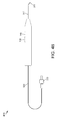
FIG. 3 is a schematic diagram illustrating an exploded view of a steerable laser probe assembly 300. Illustratively, a steerable laser probe assembly 300 may comprise a handle end cap 110, an actuation mechanism 120, a handle base 140, a flexible housing tube 310 having a flexible housing tube distal end 311 and a flexible housing tube proximal end 312, an optic fiber 320 having an optic fiber distal end 321 and an optic fiber proximal end 322, and a light source interface 330. Illustratively, light source interface 330 may be configured to interface with optic fiber 320, e.g., at optic fiber proximal end 322. In one or more embodiments, light source interface 330 may comprise a standard light source connecter, e.g., an SMA connector.
Illustratively, a portion of flexible housing tube 310 may be fixed to actuation mechanism 120, e.g., flexible housing tube proximal end 312 may be fixed to actuation mechanism distal end 121. In one or more embodiments, a portion of flexible housing tube 310 may be fixed to actuation mechanism 120, e.g., by an adhesive or any suitable fixation means. Illustratively, a portion of flexible housing tube 310 may be disposed within actuation mechanism 120, e.g., flexible housing tube proximal end 312 may be disposed within flexible housing tube housing 170. In one or more embodiments, a portion of flexible housing tube 310 may be fixed within flexible housing tube housing 170, e.g., by an adhesive or any suitable fixation means. Illustratively, flexible housing tube 310 may be disposed within actuation mechanism guide 150 and flexible housing tube guide 190. In one or more embodiments, a portion of flexible housing tube 310 may extend from handle distal end 201, e.g., flexible housing tube distal end 311 may extend from handle distal end 201. Flexible housing tube 310 may be manufactured from any suitable material, e.g., polymers, metals, metal alloys, etc., or from any combination of suitable materials.
Illustratively, flexible housing tube 310 may comprise a shape memory material, e.g., Nitinol. In one or more embodiments, flexible housing tube 310 may be manufactured from a material having an ultimate tensile strength between 700 and 1000 MPa. Illustratively, flexible housing tube 310 may be manufactured from a material having ultimate tensile strength less than 700 MPa or greater than 1000 MPa. In one or more embodiments, flexible housing tube 310 may be manufactured from a material having a modulus of elasticity between 30 and 80 GPa. Illustratively, flexible housing tube 310 may be manufactured from a material having a modulus of elasticity less than 30 GPa or greater than 80 GPa.
In one or more embodiments, flexible housing tube 310 may be manufactured with dimensions suitable for performing microsurgical procedures, e.g., ophthalmic surgical procedures. Illustratively, flexible housing tube 310 may be manufactured at gauge sizes commonly used in ophthalmic surgical procedures, e.g., 23 gauge, 25 gauge, etc. In one or more embodiments, flexible housing tube 310 may be configured to be inserted in a cannula, e.g., a cannula used during an ophthalmic surgical procedure. For example, one or more properties of flexible housing tube 310 may be optimized to reduce friction as flexible housing tube 310 is inserted into a cannula. In one or more embodiments, one or more properties of flexible housing tube 310 may be optimized to reduce friction as flexible housing tube 310 is removed from a cannula. Illustratively, flexible housing tube 310 may have an ultimate tensile strength between 1000 MPa and 1100 MPa. In one or more embodiments, flexible housing tube 310 may have an ultimate tensile strength less than 1000 MPa or greater than 1100 MPa.
In one or more embodiments, optic fiber 320 may be disposed in optic fiber housing 160, actuation mechanism guide 150, inner bore 165, flexible housing tube housing 170, flexible housing tube 310, and flexible housing tube guide 190. Illustratively, optic fiber 320 may be disposed within flexible housing tube 310 wherein optic fiber distal end 321 may be adjacent to flexible housing tube distal end 311. In one or more embodiments, a portion of optic fiber 320 may be fixed to a portion of flexible housing tube 310, e.g., by an adhesive or any suitable fixation means. Illustratively, a portion of optic fiber 320 may be fixed in a position relative to handle base 140. In one or more embodiments, a portion of optic fiber 320 may be fixed within optic fiber housing 160, e.g., by an adhesive or any suitable fixation means. Illustratively, optic fiber 320 may be fixed in a position relative to handle base 140 and a portion of optic fiber 320 may be fixed to a portion of flexible housing tube 310.
In one or more embodiments, an actuation of actuation mechanism control 130 towards actuation mechanism control guide distal end 146 and away from actuation mechanism control guide proximal end 147 may be configured to extend actuation mechanism 120 relative to handle proximal end 202. Illustratively, an extension of actuation mechanism 120 relative to handle proximal end 202 may be configured to extend flexible housing tube housing 170 relative to handle proximal end 202. In one or more embodiments, an extension of flexible housing tube housing 170 relative to handle proximal end 202 may be configured to extend flexible housing tube 310 relative to handle proximal end 202. Illustratively, an extension of actuation mechanism control 130 relative to actuation mechanism control guide proximal end 147 may be configured to extend flexible housing tube 310 relative to handle proximal end 202. In one or more embodiments, an extension of flexible housing tube 310 relative to handle proximal end 202 may be configured to extend flexible housing tube 310 relative to optic fiber 320. Illustratively, a portion of optic fiber 320, e.g., a portion of optic fiber 320 fixed to flexible housing tube 310, may be configured to resist an extension of flexible housing tube 310 relative to optic fiber 320. In one or more embodiments, as flexible housing tube 310 is extended relative to optic fiber 320, e.g., due to an extension of actuation mechanism control 130 relative to actuation mechanism control guide proximal end 147, a portion of optic fiber 320 may be configured to apply a force to a portion of flexible housing tube 310. Illustratively, an application of a force to a portion of flexible housing tube 310 may be configured to cause flexible housing tube 310 to gradually curve, e.g., by compressing a portion of flexible housing tube 310. In one or more embodiments, a gradual curving of flexible housing tube 310 may be configured to gradually curve optic fiber 320. Illustratively, an extension of actuation mechanism control 130 relative to handle proximal end 202 may be configured to gradually curve optic fiber 320.
In one or more embodiments, an actuation of actuation mechanism control 130 towards actuation mechanism control guide proximal end 147 and away from actuation mechanism control guide distal end 146 may be configured to retract actuation mechanism 120 relative to handle proximal end 202. Illustratively, a retraction of actuation mechanism 120 relative to handle proximal end 202 may be configured to retract flexible housing tube housing 170 relative to handle proximal end 202. In one or more embodiments, a refraction of flexible housing tube housing 170 relative to handle proximal end 202 may be configured to retract flexible housing tube 310 relative to handle proximal end 202. Illustratively, a retraction of actuation mechanism control 130 relative to actuation mechanism control guide proximal end 147 may be configured to retract flexible housing tube 310 relative to handle proximal end 202. In one or more embodiments, a refraction of flexible housing tube 310 relative to handle proximal end 202 may be configured to retract flexible housing tube 310 relative to optic fiber 320. Illustratively, a portion of optic fiber 320, e.g., a portion of optic fiber 320 fixed to flexible housing tube 310, may be configured to facilitate a retraction of flexible housing tube 310 relative to optic fiber 320. In one or more embodiments, as flexible housing tube 310 is retracted relative to optic fiber 320, e.g., due to a refraction of actuation mechanism control 130 relative to actuation mechanism control guide proximal end 147, a portion of optic fiber 320 may be configured to reduce a force applied to a portion of flexible housing tube 310. Illustratively, a reduction of a force applied to a portion of flexible housing tube 310 may be configured to cause flexible housing tube 310 to gradually straighten, e.g., by decompressing a portion of flexible housing tube 310. In one or more embodiments, a gradual straightening of flexible housing tube 310 may be configured to gradually straighten optic fiber 320. Illustratively, a retraction of actuation mechanism control 130 relative to handle proximal end 202 may be configured to gradually straighten optic fiber 320.
FIGS. 4A, 4B, 4C, 4D, and 4E illustrate a gradual curving of an optic fiber 320. FIG. 4A illustrates a straight optic fiber 400. In one or more embodiments, optic fiber 320 may comprise a straight optic fiber 400, e.g., when flexible housing tube 310 is fully refracted relative to handle proximal end 202. Illustratively, optic fiber 320 may comprise a straight optic fiber 400, e.g., when actuation mechanism control 130 is fully retracted relative to actuation mechanism control guide proximal end 147. In one or more embodiments, optic fiber 320 may comprise a straight optic fiber 400, e.g., when actuation mechanism 120 is fully retracted relative to handle proximal end 202. Illustratively, a line tangent to optic fiber distal end 321 may be parallel to a line tangent to flexible housing tube proximal end 312, e.g., when optic fiber 320 comprises a straight optic fiber 400.
FIG. 4B illustrates an optic fiber in a first curved position 410. In one or more embodiments, an extension of actuation mechanism control 130 relative to handle proximal end 202 may be configured to gradually curve optic fiber 320 from a straight optic fiber 400 to an optic fiber in a first curved position 410. Illustratively, an extension of actuation mechanism control 130 relative to handle proximal end 202 may be configured to extend actuation mechanism 120 relative to handle proximal end 202. In one or more embodiments, an extension of actuation mechanism 120 relative to handle proximal end 202 may be configured to extend flexible housing tube 310 relative to optic fiber 320. Illustratively, an extension of flexible housing tube 310 relative to optic fiber 320 may be configured to apply a force to a portion of flexible housing tube 310. In one or more embodiments, an application of a force to a portion of flexible housing tube 310 may be configured to cause flexible housing tube 310 to gradually curve, e.g., by compressing a portion of flexible housing tube 310. Illustratively, a gradual curving of flexible housing tube 310 may be configured to gradually curve optic fiber 320, e.g., from a straight optic fiber 400 to an optic fiber in a first curved position 410. In one or more embodiments, a line tangent to optic fiber distal end 321 may intersect a line tangent to flexible housing tube proximal end 312 at a first angle, e.g., when optic fiber 320 comprises an optic fiber in a first curved position 410. Illustratively, the first angle may comprise any angle greater than zero degrees. For example, the first angle may comprise a 45 degree angle.
FIG. 4C illustrates an optic fiber in a second curved position 420. In one or more embodiments, an extension of actuation mechanism control 130 relative to handle proximal end 202 may be configured to gradually curve optic fiber 320 from an optic fiber in a first curved position 410 to an optic fiber in a second curved position 420. Illustratively, an extension of actuation mechanism control 130 relative to handle proximal end 202 may be configured to extend actuation mechanism 120 relative to handle proximal end 202. In one or more embodiments, an extension of actuation mechanism 120 relative to handle proximal end 202 may be configured to extend flexible housing tube 310 relative to optic fiber 320. Illustratively, an extension of flexible housing tube 310 relative to optic fiber 320 may be configured to apply a force to a portion of flexible housing tube 310. In one or more embodiments, an application of a force to a portion of flexible housing tube 310 may be configured to cause flexible housing tube 310 to gradually curve, e.g., by compressing a portion of flexible housing tube 310. Illustratively, a gradual curving of flexible housing tube 310 may be configured to gradually curve optic fiber 320, e.g., from an optic fiber in a first curved position 410 to an optic fiber in a second curved position 420. In one or more embodiments, a line tangent to optic fiber distal end 321 may intersect a line tangent to flexible housing tube proximal end 312 at a second angle, e.g., when optic fiber 320 comprises an optic fiber in a second curved position 420. Illustratively, the second angle may comprise any angle greater than the first angle. For example, the second angle may comprise a 90 degree angle.
FIG. 4D illustrates an optic fiber in a third curved position 430. In one or more embodiments, an extension of actuation mechanism control 130 relative to handle proximal end 202 may be configured to gradually curve optic fiber 320 from an optic fiber in a second curved position 420 to an optic fiber in a third curved position 430. Illustratively, an extension of actuation mechanism control 130 relative to handle proximal end 202 may be configured to extend actuation mechanism 120 relative to handle proximal end 202. In one or more embodiments, an extension of actuation mechanism 120 relative to handle proximal end 202 may be configured to extend flexible housing tube 310 relative to optic fiber 320. Illustratively, an extension of flexible housing tube 310 relative to optic fiber 320 may be configured to apply a force to a portion of flexible housing tube 310. In one or more embodiments, an application of a force to a portion of flexible housing tube 310 may be configured to cause flexible housing tube 310 to gradually curve, e.g., by compressing a portion of flexible housing tube 310. Illustratively, a gradual curving of flexible housing tube 310 may be configured to gradually curve optic fiber 320, e.g., from an optic fiber in a second curved position 420 to an optic fiber in a third curved position 430. In one or more embodiments, a line tangent to optic fiber distal end 321 may intersect a line tangent to flexible housing tube proximal end 312 at a third angle, e.g., when optic fiber 320 comprises an optic fiber in a third curved position 430. Illustratively, the third angle may comprise any angle greater than the second angle. For example, the third angle may comprise a 135 degree angle.
FIG. 4E illustrates an optic fiber in a fourth curved position 440. In one or more embodiments, an extension of actuation mechanism control 130 relative to handle proximal end 202 may be configured to gradually curve optic fiber 320 from an optic fiber in a third curved position 430 to an optic fiber in a fourth curved position 440. Illustratively, an extension of actuation mechanism control 130 relative to handle proximal end 202 may be configured to extend actuation mechanism 120 relative to handle proximal end 202. In one or more embodiments, an extension of actuation mechanism 120 relative to handle proximal end 202 may be configured to extend flexible housing tube 310 relative to optic fiber 320. Illustratively, an extension of flexible housing tube 310 relative to optic fiber 320 may be configured to apply a force to a portion of flexible housing tube 310. In one or more embodiments, an application of a force to a portion of flexible housing tube 310 may be configured to cause flexible housing tube 310 to gradually curve, e.g., by compressing a portion of flexible housing tube 310. Illustratively, a gradual curving of flexible housing tube 310 may be configured to gradually curve optic fiber 320, e.g., from an optic fiber in a third curved position 430 to an optic fiber in a fourth curved position 440. In one or more embodiments, a line tangent to optic fiber distal end 321 may be parallel to a line tangent to flexible housing tube proximal end 312, e.g., when optic fiber 320 comprises an optic fiber in a fourth curved position 440.
In one or more embodiments, one or more properties of a steerable laser probe may be adjusted to attain one or more desired steerable laser probe features. For example, a length that flexible housing tube distal end 311 extends from actuation mechanism distal end 121 may be adjusted to vary an amount of extension of actuation mechanism control 130 relative to handle proximal end 202 configured to curve flexible housing tube 310 to a particular curved position. In one or more embodiments, a stiffness of flexible housing tube 310 may be adjusted to vary an amount of extension of actuation mechanism control 130 relative to handle proximal end 202 configured to curve flexible housing tube 310 to a particular curved position. Illustratively, flexible housing tube 310 may comprise a solid tube structure. In one or more embodiments, flexible housing tube 310 may comprise one or more apertures, e.g., configured to vary a stiffness of flexible housing tube 310. Illustratively, a material comprising flexible housing tube 310 may be adjusted to vary an amount of extension of actuation mechanism control 130 relative to handle proximal end 202 configured to curve flexible housing tube 310 to a particular curved position. In one or more embodiments, a stiffness of flexible housing tube 310 may be adjusted to vary a bend radius of flexible housing tube 310. For example, a stiffness of flexible housing tube 310 may be adjusted to vary a radius of curvature of flexible housing tube 310, e.g., when flexible housing tube 310 is in a particular curved position.
In one or more embodiments, a geometry of actuation mechanism 120 may be adjusted to vary an amount of extension of actuation mechanism control 130 relative to handle proximal end 202 configured to curve flexible housing tube 310 to a particular curved position. Illustratively, a geometry of actuation mechanism guide 150 may be adjusted to vary an amount of extension of actuation mechanism control 130 relative to handle proximal end 202 configured to curve flexible housing tube 310 to a particular curved position. In one or more embodiments, a geometry of handle end cap 110 or a geometry of handle base 140 may be adjusted to vary an amount of extension of actuation mechanism control 130 relative to handle proximal end 202 configured to curve flexible housing tube 310 to a particular curved position. Illustratively, one or more locations within flexible housing tube 310 wherein optic fiber 320 may be fixed to a portion of flexible housing tube 310 may be adjusted to vary an amount of extension of actuation mechanism control 130 relative to handle proximal end 202 configured to curve flexible housing tube 310 to a particular curved position.
In one or more embodiments, at least a portion of optic fiber 320 may be enclosed in an optic fiber sleeve configured to, e.g., protect optic fiber 320, vary a stiffness of optic fiber 320, vary an optical property of optic fiber 320, etc. Illustratively, an optic fiber sleeve may be configured to compress a portion of flexible housing tube 310. For example, an optic fiber sleeve may enclose a portion of optic fiber 320 and the optic fiber sleeve may be fixed in a position relative to handle base 140, e.g., the optic fiber sleeve may be fixed within optic fiber housing 160 by an adhesive or any suitable fixation means. Illustratively, a portion of the optic fiber sleeve may be fixed to a portion of flexible housing tube 310, e.g., by an adhesive or any suitable fixation means. In one or more embodiments, an extension of actuation mechanism control 130 relative to handle proximal end 202 may be configured to extend flexible housing tube 310 relative to an optic fiber sleeve. Illustratively, an extension of flexible housing tube 310 relative to an optic fiber sleeve may be configured to cause the optic fiber sleeve to apply a force, e.g., a compressive force, to a portion of flexible housing tube 310 causing flexible housing tube 310 to gradually curve. In one or more embodiments, a gradual curving of flexible housing tube 310 may be configured to gradually curve optic fiber 320.
Illustratively, optic fiber 320 may comprise a buffer, a cladding disposed in the buffer, and a core disposed in the cladding. In one or more embodiments, at least a portion of optic fiber 320 may comprise a buffer configured to protect an optical property of optic fiber 320. Illustratively, at least a portion of optic fiber 320 may comprise a buffer configured to protect an optical layer of optic fiber 320, e.g., the buffer may protect an optical layer of a curved portion of optic fiber 320. In one or more embodiments, at least a portion of optic fiber 320 may comprise a polyimide buffer configured to protect an optical property of optic fiber 320. For example, at least a portion of optic fiber 320 may comprise a Kapton buffer configured to protect an optical property of optic fiber 320.
Illustratively, a steerable laser probe may be configured to indicate, e.g., to a surgeon, a direction that optic fiber 320 may curve, e.g., due to an extension of actuation mechanism control 130 relative to handle proximal end 202. In one or more embodiments, a portion of a steerable laser probe, e.g., handle 200, may be marked in a manner configured to indicate a direction that optic fiber 320 may curve. For example, a portion of flexible housing tube 310 may comprise a mark configured to indicate a direction that optic fiber 320 may curve. Illustratively, flexible housing tube 310 may comprise a slight curve, e.g., a curve less than 7.5 degrees, when actuation mechanism control 130 is fully refracted relative to handle proximal end 202. In one or more embodiments, flexible housing tube 310 may comprise a slight curve configured to indicate a direction that optic fiber 320 may curve, e.g., due to an extension of actuation mechanism control 130 relative to handle proximal end 202.
Illustratively, handle base 140 may comprise a plurality of actuation mechanism control guides 145. In one or more embodiments, actuation mechanism 120 may comprise a plurality of actuation mechanism controls 130. For example, handle 200 may comprise a first actuation mechanism control 130 disposed within a first actuation mechanism control guide 145 and a second actuation mechanism control 130 disposed in a second actuation mechanism control guide 145. Illustratively, an extension of either the first actuation mechanism control 130 or the second actuation mechanism control 130 relative to handle proximal end 202 may be configured to extend actuation mechanism 120 relative to handle proximal end 202. In one or more embodiments, a retraction of either the first actuation mechanism control 130 or the second actuation mechanism control 130 relative to handle proximal end 202 may be configured to retract actuation mechanism 120 relative to handle proximal end 202. Illustratively, handle 200 may comprise a third actuation mechanism control 130 disposed in a third actuation mechanism control guide 145. In one or more embodiments, an extension of either the first actuation mechanism control 130, the second actuation mechanism control 130, or the third actuation mechanism control 130 relative to handle proximal end 202 may be configured to extend actuation mechanism 120 relative to handle proximal end 202. Illustratively, a retraction of either the first actuation mechanism control 130, the second actuation mechanism control 130, or the third actuation mechanism control 130 relative to handle proximal end 202 may be configured to retract actuation mechanism 120 relative to handle proximal end 202.
In one or more embodiments, a steerable laser probe may comprise a pressure mechanism configured to provide a force. Illustratively, a pressure mechanism may be disposed within pressure mechanism housing 180. In one or more embodiments, a pressure mechanism may be configured to provide a constant force. Illustratively, a pressure mechanism may be configured to provide a variable force. In one or more embodiments, a pressure mechanism may be configured to provide a resistive force, e.g., to resist an extension of actuation mechanism 120 relative to handle proximal end 202. Illustratively, a pressure mechanism may be configured to provide a facilitating force, e.g., to facilitate a retraction of actuation mechanism 120 relative to handle proximal end 202. In one or more embodiments, a pressure mechanism may comprise a spring or a coil. Illustratively, a pressure mechanism may comprise a pneumatic system or any system configured to provide a force.
FIGS. 5A, 5B, 5C, 5D, and 5E illustrate a gradual straightening of an optic fiber 320. FIG. 5A illustrates a fully curved optic fiber 500. In one or more embodiments, optic fiber 320 may comprise a fully curved optic fiber 500, e.g., when flexible housing tube 310 is fully extended relative to handle proximal end 202. Illustratively, optic fiber 320 may comprise a fully curved optic fiber 500, e.g., when actuation mechanism control 130 is fully extended relative to actuation mechanism control guide proximal end 147. In one or more embodiments, optic fiber 320 may comprise a fully curved optic fiber 500, e.g., when actuation mechanism 120 is fully extended relative to handle proximal end 202. Illustratively, a line tangent to optic fiber distal end 321 may be parallel to a line tangent to flexible housing tube proximal end 312, e.g., when optic fiber 320 comprises a fully curved optic fiber 500.
FIG. 5B illustrates an optic fiber in a first partially straightened position 510. In one or more embodiments, a retraction of actuation mechanism control 130 relative to handle proximal end 202 may be configured to gradually straighten optic fiber 320 from a fully curved optic fiber 500 to an optic fiber in a first partially straightened position 510. Illustratively, a retraction of actuation mechanism control 130 relative to handle proximal end 202 may be configured to retract actuation mechanism 120 relative to handle proximal end 202. In one or more embodiments, a retraction of actuation mechanism 120 relative to handle proximal end 202 may be configured to retract flexible housing tube 310 relative to optic fiber 320. Illustratively, a retraction of flexible housing tube 310 relative to optic fiber 320 may be configured to reduce a force applied to a portion of flexible housing tube 310. In one or more embodiments, a reduction of a force applied to a portion of flexible housing tube 310 may be configured to cause flexible housing tube 310 to gradually straighten, e.g., by decompressing a portion of flexible housing tube 310. Illustratively, a gradual straightening of flexible housing tube 310 may be configured to gradually straighten optic fiber 320, e.g., from a fully curved optic fiber 500 to an optic fiber in a first partially straightened position 510. In one or more embodiments, a line tangent to optic fiber distal end 321 may intersect a line tangent to flexible housing tube proximal end 312 at a first partially straightened angle, e.g., when optic fiber 320 comprises an optic fiber in a first partially straightened position 510. Illustratively, the first partially straightened angle may comprise any angle less than 180 degrees. For example, the first partially straightened angle may comprise a 135 degree angle.
FIG. 5C illustrates an optic fiber in a second partially straightened position 520. In one or more embodiments, a retraction of actuation mechanism control 130 relative to handle proximal end 202 may be configured to gradually straighten optic fiber 320 from an optic fiber in a first partially straightened position 510 to an optic fiber in a second partially straightened position 520. Illustratively, a retraction of actuation mechanism control 130 relative to handle proximal end 202 may be configured to retract actuation mechanism 120 relative to handle proximal end 202. In one or more embodiments, a retraction of actuation mechanism 120 relative to handle proximal end 202 may be configured to retract flexible housing tube 310 relative to optic fiber 320. Illustratively, a retraction of flexible housing tube 310 relative to optic fiber 320 may be configured to reduce a force applied to a portion of flexible housing tube 310. In one or more embodiments, a reduction of a force applied to a portion of flexible housing tube 310 may be configured to cause flexible housing tube 310 to gradually straighten, e.g., by decompressing a portion of flexible housing tube 310. Illustratively, a gradual straightening of flexible housing tube 310 may be configured to gradually straighten optic fiber 320, e.g., from an optic fiber in a first partially straightened position 510 to an optic fiber in a second partially straightened position 520. In one or more embodiments, a line tangent to optic fiber distal end 321 may intersect a line tangent to flexible housing tube proximal end 312 at a second partially straightened angle, e.g., when optic fiber 320 comprises an optic fiber in a second partially straightened position 520. Illustratively, the second partially straightened angle may comprise any angle less than the first partially straightened angle. For example, the second partially straightened angle may comprise a 90 degree angle.
FIG. 5D illustrates an optic fiber in a third partially straightened position 530. In one or more embodiments, a retraction of actuation mechanism control 130 relative to handle proximal end 202 may be configured to gradually straighten optic fiber 320 from an optic fiber in a second partially straightened position 520 to an optic fiber in a third partially straightened position 530. Illustratively, a retraction of actuation mechanism control 130 relative to handle proximal end 202 may be configured to retract actuation mechanism 120 relative to handle proximal end 202. In one or more embodiments, a retraction of actuation mechanism 120 relative to handle proximal end 202 may be configured to retract flexible housing tube 310 relative to optic fiber 320. Illustratively, a retraction of flexible housing tube 310 relative to optic fiber 320 may be configured to reduce a force applied to a portion of flexible housing tube 310. In one or more embodiments, a reduction of a force applied to a portion of flexible housing tube 310 may be configured to cause flexible housing tube 310 to gradually straighten, e.g., by decompressing a portion of flexible housing tube 310. Illustratively, a gradual straightening of flexible housing tube 310 may be configured to gradually straighten optic fiber 320, e.g., from an optic fiber in a second partially straightened position 520 to an optic fiber in a third partially straightened position 530. In one or more embodiments, a line tangent to optic fiber distal end 321 may intersect a line tangent to flexible housing tube proximal end 312 at a third partially straightened angle, e.g., when optic fiber 320 comprises an optic fiber in a third partially straightened position 530. Illustratively, the third partially straightened angle may comprise any angle less than the second partially straightened angle. For example, the third partially straightened angle may comprise a 45 degree angle.
FIG. 5E illustrates an optic fiber in a fully straightened position 540. In one or more embodiments, a retraction of actuation mechanism control 130 relative to handle proximal end 202 may be configured to gradually straighten optic fiber 320 from an optic fiber in a third partially straightened position 530 to an optic fiber in a fully straightened position 540. Illustratively, a retraction of actuation mechanism control 130 relative to handle proximal end 202 may be configured to retract actuation mechanism 120 relative to handle proximal end 202. In one or more embodiments, a retraction of actuation mechanism 120 relative to handle proximal end 202 may be configured to retract flexible housing tube 310 relative to optic fiber 320. Illustratively, a retraction of flexible housing tube 310 relative to optic fiber 320 may be configured to reduce a force applied to a portion of flexible housing tube 310. In one or more embodiments, a reduction of a force applied to a portion of flexible housing tube 310 may be configured to cause flexible housing tube 310 to gradually straighten, e.g., by decompressing a portion of flexible housing tube 310. Illustratively, a gradual straightening of flexible housing tube 310 may be configured to gradually straighten optic fiber 320, e.g., from an optic fiber in a third partially straightened position 530 to an optic fiber in a fully straightened position 540. In one or more embodiments, a line tangent to optic fiber distal end 321 may be parallel to a line tangent to flexible housing tube proximal end 312, e.g., when optic fiber 320 comprises an optic fiber in a fully straightened position 540.
Illustratively, a surgeon may aim optic fiber distal end 321 at any of a plurality of targets within an eye, e.g., to perform a photocoagulation procedure, to illuminate a surgical target site, etc. In one or more embodiments, a surgeon may aim optic fiber distal end 321 at any target within a particular transverse plane of the inner eye by, e.g., rotating handle 200 to orient flexible housing tube 310 in an orientation configured to cause a curvature of flexible housing tube 310 within the particular transverse plane of the inner eye and varying an amount of extension of actuation mechanism control 130 relative to handle proximal end 202. Illustratively, a surgeon may aim optic fiber distal end 321 at any target within a particular sagittal plane of the inner eye by, e.g., rotating handle 200 to orient flexible housing tube 310 in an orientation configured to cause a curvature of flexible housing tube 310 within the particular sagittal plane of the inner eye and varying an amount of extension of actuation mechanism control 130 relative to handle proximal end 202. In one or more embodiments, a surgeon may aim optic fiber distal end 321 at any target within a particular frontal plane of the inner eye by, e.g., varying an amount of extension of actuation mechanism control 130 relative to handle proximal end 202 to orient a line tangent to optic fiber distal end 321 wherein the line tangent to optic fiber distal end 321 is within the particular frontal plane of the inner eye and rotating handle 200. Illustratively, a surgeon may aim optic fiber distal end 321 at any target located outside of the particular transverse plane, the particular sagittal plane, and the particular frontal plane of the inner eye, e.g., by varying a rotational orientation of handle 200 and varying an amount of extension of actuation mechanism control 130 relative to handle proximal end 202. In one or more embodiments, a surgeon may aim optic fiber distal end 321 at any target of a plurality of targets within an eye, e.g., without increasing a length of a portion of a steerable laser probe within the eye. Illustratively, a surgeon may aim optic fiber distal end 321 at any target of a plurality of targets within an eye, e.g., without decreasing a length of a portion of a steerable laser probe within the eye.
FIGS. 6A and 6B are schematic diagrams illustrating an exploded view of a handle assembly 600. FIG. 6A illustrates a side-view of a handle assembly 600. Illustratively, handle assembly 600 may comprise a handle end cap 610 having a handle end cap distal end 611 and a handle end cap proximal end 612, an actuation mechanism 620 having an actuation mechanism distal end 621 and an actuation mechanism proximal end 622, an actuation mechanism control 630 having an actuation mechanism control distal end 631 and an actuation mechanism control proximal end 632, and a handle base 640 having a handle base distal end 641 and a handle base proximal end 642. In one or more embodiments, handle base 640 may comprise a handle end cap interface 643 and an actuation mechanism control guide 645 having an actuation mechanism control guide distal end 646 and an actuation mechanism control guide proximal end 647.
FIG. 6B illustrates a cross-sectional view of a handle assembly 600. Illustratively, handle assembly 600 may comprise an actuation mechanism guide 650, a handle base interface 653, a handle base housing 655, a wire housing 660, an inner bore 665, a flexible housing tube housing 670, a pressure mechanism housing 680, and a flexible housing tube guide 690. Handle end cap 610, actuation mechanism 620, actuation mechanism control 630, and handle base 640 may be manufactured from any suitable material, e.g., polymers, metals, metal alloys, etc., or from any combination of suitable materials.
FIGS. 7A and 7B are schematic diagrams illustrating a handle 700. FIG. 7A illustrates a side-view of a handle 700. Illustratively, handle 700 may comprise a handle distal end 701, a handle proximal end 702, a handle end cap 610, an actuation mechanism 620, an actuation mechanism control 630, and a handle base 640. In one or more embodiments, handle distal end 701 may comprise handle base distal end 641. Illustratively, handle proximal end 702 may comprise handle end cap proximal end 612. In one or more embodiments, actuation mechanism control 630 may be disposed within actuation mechanism control guide 645. Illustratively, actuation mechanism control 630 may be configured to control an actuation of actuation mechanism 620, e.g., an actuation of actuation mechanism 620 within actuation mechanism guide 650.
FIG. 7B illustrates a cross-sectional view of a handle 700. Illustratively, handle 700 may be assembled by disposing actuation mechanism 620 within actuation mechanism guide 650. In one or more embodiments, at least a portion of actuation mechanism guide 650 may be coated by a lubricant, e.g., Teflon, configured to facilitate an actuation of actuation mechanism 620 within actuation mechanism guide 650. Illustratively, a portion of handle end cap 610 may be adjacent to a portion of handle base 640, e.g., handle end cap distal end 611 may be adjacent to handle base proximal end 642. In one or more embodiments, a portion of handle base 640 may be disposed within handle end cap 610, e.g., handle base proximal end 642 may be disposed within handle base housing 655. Illustratively, a portion of handle base 640 may be disposed within handle end cap 610 wherein handle end cap interface 643 may be adjacent to handle base interface 653. In one or more embodiments, a portion of handle end cap 610 may be fixed to a portion of handle base 640, e.g., by an adhesive or any suitable fixation means. Illustratively, handle end cap 610 and handle base 640 may be manufactured as a single unit.
Illustratively, actuation mechanism 620 may be configured to actuate within actuation mechanism guide 650. In one or more embodiments, an actuation of actuation mechanism control 630 may be configured to actuate actuation mechanism 620 within actuation mechanism guide 650. Illustratively, an actuation of actuation mechanism control 630 towards actuation mechanism control guide distal end 646 and away from actuation mechanism control guide proximal end 647 may be configured to actuate actuation mechanism 620, e.g., towards handle distal end 701 and away from handle proximal end 702. In one or more embodiments, an actuation of actuation mechanism control 630 towards actuation mechanism control guide proximal end 647 and away from actuation mechanism control guide distal end 646 may be configured to actuate actuation mechanism 620, e.g., towards handle proximal end 702 and away from handle distal end 701.
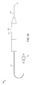
FIG. 8 is a schematic diagram illustrating an exploded view of a steerable laser probe assembly 800. Illustratively, a steerable laser probe assembly 800 may comprise a handle end cap 610, an actuation mechanism 620, a handle base 640, a flexible housing tube 310 having a flexible housing tube distal end 311 and a flexible housing tube proximal end 312, an optic fiber 320 having an optic fiber distal end 321 and an optic fiber proximal end 322, a wire 810 having a wire distal end 811 and a wire proximal end 812, and a light source interface 330. Illustratively, light source interface 330 may be configured to interface with optic fiber 320, e.g., at optic fiber proximal end 322. In one or more embodiments, light source interface 330 may comprise a standard light source connecter, e.g., an SMA connector.
Illustratively, a portion of flexible housing tube 310 may be fixed to actuation mechanism 620, e.g., flexible housing tube proximal end 312 may be fixed to actuation mechanism distal end 621. In one or more embodiments, a portion of flexible housing tube 310 may be fixed to actuation mechanism 620, e.g., by an adhesive or any suitable fixation means. Illustratively, a portion of flexible housing tube 310 may be disposed within actuation mechanism 620, e.g., flexible housing tube proximal end 312 may be disposed within flexible housing tube housing 670. In one or more embodiments, a portion of flexible housing tube 310 may be fixed within flexible housing tube housing 670, e.g., by an adhesive or any suitable fixation means. Illustratively, flexible housing tube 310 may be disposed within actuation mechanism guide 650 and flexible housing tube guide 690. In one or more embodiments, a portion of flexible housing tube 310 may extend from handle distal end 701, e.g., flexible housing tube distal end 311 may extend from handle distal end 701. Flexible housing tube 310 may be manufactured from any suitable material, e.g., polymers, metals, metal alloys, etc., or from any combination of suitable materials.
Illustratively, flexible housing tube 310 may comprise a shape memory material, e.g., Nitinol. In one or more embodiments, flexible housing tube 310 may be manufactured from a material having an ultimate tensile strength between 700 and 1000 MPa. Illustratively, flexible housing tube 310 may be manufactured from a material having ultimate tensile strength less than 700 MPa or greater than 1000 MPa. In one or more embodiments, flexible housing tube 310 may be manufactured from a material having a modulus of elasticity between 30 and 80 GPa. Illustratively, flexible housing tube 310 may be manufactured from a material having a modulus of elasticity less than 30 GPa or greater than 80 GPa.
In one or more embodiments, flexible housing tube 310 may be manufactured with dimensions suitable for performing microsurgical procedures, e.g., ophthalmic surgical procedures. Illustratively, flexible housing tube 310 may be manufactured at gauge sizes commonly used in ophthalmic surgical procedures, e.g., 23 gauge, 25 gauge, etc. In one or more embodiments, flexible housing tube 310 may be configured to be inserted in a cannula, e.g., a cannula used during an ophthalmic surgical procedure. For example, one or more properties of flexible housing tube 310 may be optimized to reduce friction as flexible housing tube 310 is inserted into a cannula. In one or more embodiments, one or more properties of flexible housing tube 310 may be optimized to reduce friction as flexible housing tube 310 is removed from a cannula. Illustratively, flexible housing tube 310 may have an ultimate tensile strength between 1000 MPa and 1100 MPa. In one or more embodiments, flexible housing tube 310 may have an ultimate tensile strength less than 1000 MPa or greater than 1100 MPa.
In one or more embodiments, optic fiber 320 may be disposed in wire housing 660, actuation mechanism guide 650, inner bore 665, flexible housing tube housing 670, flexible housing tube 310, and flexible housing tube guide 690. Illustratively, optic fiber 320 may be disposed within flexible housing tube 310 wherein optic fiber distal end 321 may be adjacent to flexible housing tube distal end 311. In one or more embodiments, a portion of optic fiber 320 may be fixed to a portion of flexible housing tube 310, e.g., by an adhesive or any suitable fixation means.
Illustratively, wire 810 may be disposed within wire housing 660, actuation mechanism guide 650, inner bore 665, flexible housing tube housing 670, flexible housing tube 310, and flexible housing tube guide 690. In one or more embodiments, wire 810 may be disposed within flexible housing tube 310 wherein wire distal end 811 may be adjacent to flexible housing tube distal end 311. Illustratively, a portion of wire 810 may be fixed to a portion of flexible housing tube 310, e.g., by an adhesive or any suitable fixation means. In one or more embodiments, wire 810 may be fixed in a position relative to handle base 640. Illustratively, wire 810 may be fixed within wire housing 660, e.g., by an adhesive or any other suitable fixation means. In one or more embodiments, wire 810 may be fixed in a position relative to handle base 640 and a portion of wire 810 may be fixed to a portion of flexible housing tube 310.
In one or more embodiments, an actuation of actuation mechanism control 630 towards actuation mechanism control guide distal end 646 and away from actuation mechanism control guide proximal end 647 may be configured to extend actuation mechanism 620 relative to handle proximal end 702. Illustratively, an extension of actuation mechanism 620 relative to handle proximal end 702 may be configured to extend flexible housing tube housing 670 relative to handle proximal end 702. In one or more embodiments, an extension of flexible housing tube housing 670 relative to handle proximal end 702 may be configured to extend flexible housing tube 310 relative to handle proximal end 702. Illustratively, an extension of actuation mechanism control 630 relative to actuation mechanism control guide proximal end 647 may be configured to extend flexible housing tube 310 relative to handle proximal end 702. In one or more embodiments, an extension of flexible housing tube 310 relative to handle proximal end 702 may be configured to extend flexible housing tube 310 relative to wire 810. Illustratively, a portion of wire 810, e.g., a portion of wire 810 fixed to flexible housing tube 310, may be configured to resist an extension of flexible housing tube 310 relative to wire 810. In one or more embodiments, as flexible housing tube 310 is extended relative to wire 810, e.g., due to an extension of actuation mechanism control 630 relative to actuation mechanism control guide proximal end 647, a portion of wire 810 may be configured to apply a force to a portion of flexible housing tube 310. Illustratively, an application of a force to a portion of flexible housing tube 310 may be configured to cause flexible housing tube 310 to gradually curve, e.g., by compressing a portion of flexible housing tube 310. In one or more embodiments, a gradual curving of flexible housing tube 310 may be configured to gradually curve optic fiber 320. Illustratively, an extension of actuation mechanism control 630 relative to handle proximal end 702 may be configured to gradually curve optic fiber 320.
In one or more embodiments, an actuation of actuation mechanism control 630 towards actuation mechanism control guide proximal end 647 and away from actuation mechanism control guide distal end 646 may be configured to retract actuation mechanism 620 relative to handle proximal end 702. Illustratively, a retraction of actuation mechanism 620 relative to handle proximal end 702 may be configured to retract flexible housing tube housing 670 relative to handle proximal end 702. In one or more embodiments, a refraction of flexible housing tube housing 670 relative to handle proximal end 702 may be configured to retract flexible housing tube 310 relative to handle proximal end 702. Illustratively, a retraction of actuation mechanism control 630 relative to actuation mechanism control guide proximal end 647 may be configured to retract flexible housing tube 310 relative to handle proximal end 702. In one or more embodiments, a refraction of flexible housing tube 310 relative to handle proximal end 702 may be configured to retract flexible housing tube 310 relative to wire 810. Illustratively, a portion of wire 810, e.g., a portion of wire 810 fixed to flexible housing tube 310, may be configured to facilitate a retraction of flexible housing tube 310 relative to wire 810. In one or more embodiments, as flexible housing tube 310 is retracted relative to wire 810, e.g., due to a retraction of actuation mechanism control 630 relative to actuation mechanism control guide proximal end 647, a portion of wire 810 may be configured to reduce a force applied to a portion of flexible housing tube 310. Illustratively, a reduction of a force applied to a portion of flexible housing tube 310 may be configured to cause flexible housing tube 310 to gradually straighten, e.g., by decompressing a portion of flexible housing tube 310. In one or more embodiments, a gradual straightening of flexible housing tube 310 may be configured to gradually straighten optic fiber 320. Illustratively, a refraction of actuation mechanism control 630 relative to handle proximal end 702 may be configured to gradually straighten optic fiber 320.
FIGS. 9A, 9B, 9C, 9D, and 9E illustrate a gradual curving of an optic fiber 320. FIG. 9A illustrates a straight optic fiber 900. In one or more embodiments, optic fiber 320 may comprise a straight optic fiber 900, e.g., when flexible housing tube 310 is fully refracted relative to handle proximal end 702. Illustratively, optic fiber 320 may comprise a straight optic fiber 900, e.g., when actuation mechanism control 630 is fully retracted relative to actuation mechanism control guide proximal end 647. In one or more embodiments, optic fiber 320 may comprise a straight optic fiber 900, e.g., when actuation mechanism 620 is fully retracted relative to handle proximal end 702. Illustratively, a line tangent to optic fiber distal end 321 may be parallel to a line tangent to flexible housing tube proximal end 312, e.g., when optic fiber 320 comprises a straight optic fiber 900.
FIG. 9B illustrates an optic fiber in a first curved position 910. In one or more embodiments, an extension of actuation mechanism control 630 relative to handle proximal end 702 may be configured to gradually curve optic fiber 320 from a straight optic fiber 900 to an optic fiber in a first curved position 910. Illustratively, an extension of actuation mechanism control 630 relative to handle proximal end 702 may be configured to extend actuation mechanism 620 relative to handle proximal end 702. In one or more embodiments, an extension of actuation mechanism 620 relative to handle proximal end 702 may be configured to extend flexible housing tube 310 relative to wire 810. Illustratively, an extension of flexible housing tube 310 relative to wire 810 may be configured to apply a force to a portion of flexible housing tube 310. In one or more embodiments, an application of a force to a portion of flexible housing tube 310 may be configured to cause flexible housing tube 310 to gradually curve, e.g., by compressing a portion of flexible housing tube 310. Illustratively, a gradual curving of flexible housing tube 310 may be configured to gradually curve optic fiber 320, e.g., from a straight optic fiber 900 to an optic fiber in a first curved position 910. In one or more embodiments, a line tangent to optic fiber distal end 321 may intersect a line tangent to flexible housing tube proximal end 312 at a first angle, e.g., when optic fiber 320 comprises an optic fiber in a first curved position 910. Illustratively, the first angle may comprise any angle greater than zero degrees. For example, the first angle may comprise a 45 degree angle.
FIG. 9C illustrates an optic fiber in a second curved position 920. In one or more embodiments, an extension of actuation mechanism control 630 relative to handle proximal end 702 may be configured to gradually curve optic fiber 320 from an optic fiber in a first curved position 910 to an optic fiber in a second curved position 920. Illustratively, an extension of actuation mechanism control 630 relative to handle proximal end 702 may be configured to extend actuation mechanism 620 relative to handle proximal end 702. In one or more embodiments, an extension of actuation mechanism 620 relative to handle proximal end 702 may be configured to extend flexible housing tube 310 relative to wire 810. Illustratively, an extension of flexible housing tube 310 relative to wire 810 may be configured to apply a force to a portion of flexible housing tube 310. In one or more embodiments, an application of a force to a portion of flexible housing tube 310 may be configured to cause flexible housing tube 310 to gradually curve, e.g., by compressing a portion of flexible housing tube 310. Illustratively, a gradual curving of flexible housing tube 310 may be configured to gradually curve optic fiber 320, e.g., from an optic fiber in a first curved position 910 to an optic fiber in a second curved position 920. In one or more embodiments, a line tangent to optic fiber distal end 321 may intersect a line tangent to flexible housing tube proximal end 312 at a second angle, e.g., when optic fiber 320 comprises an optic fiber in a second curved position 920. Illustratively, the second angle may comprise any angle greater than the first angle. For example, the second angle may comprise a 90 degree angle.
FIG. 9D illustrates an optic fiber in a third curved position 930. In one or more embodiments, an extension of actuation mechanism control 630 relative to handle proximal end 702 may be configured to gradually curve optic fiber 320 from an optic fiber in a second curved position 920 to an optic fiber in a third curved position 930. Illustratively, an extension of actuation mechanism control 630 relative to handle proximal end 702 may be configured to extend actuation mechanism 620 relative to handle proximal end 702. In one or more embodiments, an extension of actuation mechanism 620 relative to handle proximal end 702 may be configured to extend flexible housing tube 310 relative to wire 810. Illustratively, an extension of flexible housing tube 310 relative to wire 810 may be configured to apply a force to a portion of flexible housing tube 310. In one or more embodiments, an application of a force to a portion of flexible housing tube 310 may be configured to cause flexible housing tube 310 to gradually curve, e.g., by compressing a portion of flexible housing tube 310. Illustratively, a gradual curving of flexible housing tube 310 may be configured to gradually curve optic fiber 320, e.g., from an optic fiber in a second curved position 920 to an optic fiber in a third curved position 930. In one or more embodiments, a line tangent to optic fiber distal end 321 may intersect a line tangent to flexible housing tube proximal end 312 at a third angle, e.g., when optic fiber 320 comprises an optic fiber in a third curved position 930. Illustratively, the third angle may comprise any angle greater than the second angle. For example, the third angle may comprise a 135 degree angle.
FIG. 9E illustrates an optic fiber in a fourth curved position 940. In one or more embodiments, an extension of actuation mechanism control 630 relative to handle proximal end 702 may be configured to gradually curve optic fiber 320 from an optic fiber in a third curved position 930 to an optic fiber in a fourth curved position 940. Illustratively, an extension of actuation mechanism control 630 relative to handle proximal end 702 may be configured to extend actuation mechanism 620 relative to handle proximal end 702. In one or more embodiments, an extension of actuation mechanism 620 relative to handle proximal end 702 may be configured to extend flexible housing tube 310 relative to wire 810. Illustratively, an extension of flexible housing tube 310 relative to wire 810 may be configured to apply a force to a portion of flexible housing tube 310. In one or more embodiments, an application of a force to a portion of flexible housing tube 310 may be configured to cause flexible housing tube 310 to gradually curve, e.g., by compressing a portion of flexible housing tube 310. Illustratively, a gradual curving of flexible housing tube 310 may be configured to gradually curve optic fiber 320, e.g., from an optic fiber in a third curved position 930 to an optic fiber in a fourth curved position 940. In one or more embodiments, a line tangent to optic fiber distal end 321 may be parallel to a line tangent to flexible housing tube proximal end 312, e.g., when optic fiber 320 comprises an optic fiber in a fourth curved position 940.
In one or more embodiments, one or more properties of a steerable laser probe may be adjusted to attain one or more desired steerable laser probe features. For example, a length that flexible housing tube distal end 311 extends from actuation mechanism distal end 621 may be adjusted to vary an amount of extension of actuation mechanism control 630 relative to handle proximal end 702 configured to curve flexible housing tube 310 to a particular curved position. In one or more embodiments, a stiffness of flexible housing tube 310 may be adjusted to vary an amount of extension of actuation mechanism control 630 relative to handle proximal end 702 configured to curve flexible housing tube 310 to a particular curved position. Illustratively, flexible housing tube 310 may comprise a solid tube structure. In one or more embodiments, flexible housing tube 310 may comprise one or more apertures, e.g., configured to vary a stiffness of flexible housing tube 310. Illustratively, a material comprising flexible housing tube 310 may be adjusted to vary an amount of extension of actuation mechanism control 630 relative to handle proximal end 702 configured to curve flexible housing tube 310 to a particular curved position. In one or more embodiments, a stiffness of flexible housing tube 310 may be adjusted to vary a bend radius of flexible housing tube 310. For example, a stiffness of flexible housing tube 310 may be adjusted to vary a radius of curvature of flexible housing tube 310, e.g., when flexible housing tube 310 is in a particular curved position.
In one or more embodiments, a geometry of actuation mechanism 620 may be adjusted to vary an amount of extension of actuation mechanism control 630 relative to handle proximal end 702 configured to curve flexible housing tube 310 to a particular curved position. Illustratively, a geometry of actuation mechanism guide 650 may be adjusted to vary an amount of extension of actuation mechanism control 630 relative to handle proximal end 702 configured to curve flexible housing tube 310 to a particular curved position. In one or more embodiments, a geometry of handle end cap 610 or a geometry of handle base 640 may be adjusted to vary an amount of extension of actuation mechanism control 630 relative to handle proximal end 702 configured to curve flexible housing tube 310 to a particular curved position. Illustratively, one or more locations within flexible housing tube 310 wherein wire 810 may be fixed to a portion of flexible housing tube 310 may be adjusted to vary an amount of extension of actuation mechanism control 630 relative to handle proximal end 702 configured to curve flexible housing tube 310 to a particular curved position.
In one or more embodiments, at least a portion of optic fiber 320 may be enclosed in an optic fiber sleeve configured to, e.g., protect optic fiber 320, vary a stiffness of optic fiber 320, vary an optical property of optic fiber 320, etc. Illustratively, optic fiber 320 may comprise a buffer, a cladding disposed in the buffer, and a core disposed in the cladding. In one or more embodiments, at least a portion of optic fiber 320 may comprise a buffer configured to protect an optical property of optic fiber 320. Illustratively, at least a portion of optic fiber 320 may comprise a buffer configured to protect an optical layer of optic fiber 320, e.g., the buffer may protect an optical layer of a curved portion of optic fiber 320. In one or more embodiments, at least a portion of optic fiber 320 may comprise a polyimide buffer configured to protect an optical property of optic fiber 320. For example, at least a portion of optic fiber 320 may comprise a Kapton buffer configured to protect an optical property of optic fiber 320.
Illustratively, wire 810 may be fixed to flexible housing tube 310 at a plurality of fixation points, e.g., to vary one or more properties of a steerable laser probe. In one or more embodiments, a length of wire 810 may be adjusted to vary an amount of extension of actuation mechanism control 630 relative to handle proximal end 702 configured to curve flexible housing tube 310 to a particular curved position. Illustratively, a steerable laser probe may comprise one or more redundant wires 810. In one or more embodiments, one or more redundant wires 810 may be configured to maintain a particular curved position of flexible housing tube 310, e.g., in the event that wire 810 breaks. Illustratively, one or more redundant wires 810 may be configured to maintain a particular curved position of flexible housing tube 310, e.g., in the event that a wire 810 fixation means fails. In one or more embodiments, one or more redundant wires 810 may be configured to maintain a particular curved position of flexible housing tube 310, e.g., in the event that wire 810 is no longer configured to maintain the particular curved position of flexible housing tube 310. Illustratively, one or more redundant wires 810 may be configured to maintain a particular curved position of flexible housing tube 310 wherein wire 810 is also configured to maintain the particular curved position of flexible housing tube 310.
Illustratively, a steerable laser probe may be configured to indicate, e.g., to a surgeon, a direction that optic fiber 320 may curve, e.g., due to an extension of actuation mechanism control 630 relative to handle proximal end 702. In one or more embodiments, a portion of a steerable laser probe, e.g., handle 700, may be marked in a manner configured to indicate a direction that optic fiber 320 may curve. For example, a portion of flexible housing tube 310 may comprise a mark configured to indicate a direction that optic fiber 320 may curve. Illustratively, flexible housing tube 310 may comprise a slight curve, e.g., a curve less than 7.5 degrees, when actuation mechanism control 630 is fully refracted relative to handle proximal end 702. In one or more embodiments, flexible housing tube 310 may comprise a slight curve configured to indicate a direction that optic fiber 320 may curve, e.g., due to an extension of actuation mechanism control 630 relative to handle proximal end 702.
Illustratively, handle base 640 may comprise a plurality of actuation mechanism control guides 645. In one or more embodiments, actuation mechanism 620 may comprise a plurality of actuation mechanism controls 630. For example, handle 700 may comprise a first actuation mechanism control 630 disposed within a first actuation mechanism control guide 645 and a second actuation mechanism control 630 disposed in a second actuation mechanism control guide 645. Illustratively, an extension of either the first actuation mechanism control 630 or the second actuation mechanism control 630 relative to handle proximal end 702 may be configured to extend actuation mechanism 620 relative to handle proximal end 702. In one or more embodiments, a retraction of either the first actuation mechanism control 630 or the second actuation mechanism control 630 relative to handle proximal end 702 may be configured to retract actuation mechanism 620 relative to handle proximal end 702. Illustratively, handle 700 may comprise a third actuation mechanism control 630 disposed in a third actuation mechanism control guide 645. In one or more embodiments, an extension of either the first actuation mechanism control 630, the second actuation mechanism control 630, or the third actuation mechanism control 630 relative to handle proximal end 702 may be configured to extend actuation mechanism 620 relative to handle proximal end 702. Illustratively, a retraction of either the first actuation mechanism control 630, the second actuation mechanism control 630, or the third actuation mechanism control 630 relative to handle proximal end 702 may be configured to retract actuation mechanism 620 relative to handle proximal end 702.
In one or more embodiments, a steerable laser probe may comprise a pressure mechanism configured to provide a force. Illustratively, a pressure mechanism may be disposed within pressure mechanism housing 680. In one or more embodiments, a pressure mechanism may be configured to provide a constant force. Illustratively, a pressure mechanism may be configured to provide a variable force. In one or more embodiments, a pressure mechanism may be configured to provide a resistive force, e.g., to resist an extension of actuation mechanism 620 relative to handle proximal end 702. Illustratively, a pressure mechanism may be configured to provide a facilitating force, e.g., to facilitate a retraction of actuation mechanism 620 relative to handle proximal end 702. In one or more embodiments, a pressure mechanism may comprise a spring or a coil. Illustratively, a pressure mechanism may comprise a pneumatic system or any system configured to provide a force.
FIGS. 10A, 10B, 10C, 10D, and 10E illustrate a gradual straightening of an optic fiber 320. FIG. 10A illustrates a fully curved optic fiber 1000. In one or more embodiments, optic fiber 320 may comprise a fully curved optic fiber 1000, e.g., when flexible housing tube 310 is fully extended relative to handle proximal end 702. Illustratively, optic fiber 320 may comprise a fully curved optic fiber 1000, e.g., when actuation mechanism control 630 is fully extended relative to actuation mechanism control guide proximal end 647. In one or more embodiments, optic fiber 320 may comprise a fully curved optic fiber 1000, e.g., when actuation mechanism 620 is fully extended relative to handle proximal end 702. Illustratively, a line tangent to optic fiber distal end 321 may be parallel to a line tangent to flexible housing tube proximal end 312, e.g., when optic fiber 320 comprises a fully curved optic fiber 1000.
FIG. 10B illustrates an optic fiber in a first partially straightened position 1010. In one or more embodiments, a retraction of actuation mechanism control 630 relative to handle proximal end 702 may be configured to gradually straighten optic fiber 320 from a fully curved optic fiber 1000 to an optic fiber in a first partially straightened position 1010. Illustratively, a retraction of actuation mechanism control 630 relative to handle proximal end 702 may be configured to retract actuation mechanism 620 relative to handle proximal end 702. In one or more embodiments, a retraction of actuation mechanism 620 relative to handle proximal end 702 may be configured to retract flexible housing tube 310 relative to wire 810. Illustratively, a retraction of flexible housing tube 310 relative to wire 810 may be configured to reduce a force applied to a portion of flexible housing tube 310. In one or more embodiments, a reduction of a force applied to a portion of flexible housing tube 310 may be configured to cause flexible housing tube 310 to gradually straighten, e.g., by decompressing a portion of flexible housing tube 310. Illustratively, a gradual straightening of flexible housing tube 310 may be configured to gradually straighten optic fiber 320, e.g., from a fully curved optic fiber 1000 to an optic fiber in a first partially straightened position 1010. In one or more embodiments, a line tangent to optic fiber distal end 321 may intersect a line tangent to flexible housing tube proximal end 312 at a first partially straightened angle, e.g., when optic fiber 320 comprises an optic fiber in a first partially straightened position 1010. Illustratively, the first partially straightened angle may comprise any angle less than 180 degrees. For example, the first partially straightened angle may comprise a 135 degree angle.
FIG. 10C illustrates an optic fiber in a second partially straightened position 1020. In one or more embodiments, a retraction of actuation mechanism control 630 relative to handle proximal end 702 may be configured to gradually straighten optic fiber 320 from an optic fiber in a first partially straightened position 1010 to an optic fiber in a second partially straightened position 1020. Illustratively, a retraction of actuation mechanism control 630 relative to handle proximal end 702 may be configured to retract actuation mechanism 620 relative to handle proximal end 702. In one or more embodiments, a retraction of actuation mechanism 620 relative to handle proximal end 702 may be configured to retract flexible housing tube 310 relative to wire 810. Illustratively, a refraction of flexible housing tube 310 relative to wire 810 may be configured to reduce a force applied to a portion of flexible housing tube 310. In one or more embodiments, a reduction of a force applied to a portion of flexible housing tube 310 may be configured to cause flexible housing tube 310 to gradually straighten, e.g., by decompressing a portion of flexible housing tube 310. Illustratively, a gradual straightening of flexible housing tube 310 may be configured to gradually straighten optic fiber 320, e.g., from an optic fiber in a first partially straightened position 1010 to an optic fiber in a second partially straightened position 1020. In one or more embodiments, a line tangent to optic fiber distal end 321 may intersect a line tangent to flexible housing tube proximal end 312 at a second partially straightened angle, e.g., when optic fiber 320 comprises an optic fiber in a second partially straightened position 1020. Illustratively, the second partially straightened angle may comprise any angle less than the first partially straightened angle. For example, the second partially straightened angle may comprise a 90 degree angle.
FIG. 10D illustrates an optic fiber in a third partially straightened position 1030. In one or more embodiments, a retraction of actuation mechanism control 630 relative to handle proximal end 702 may be configured to gradually straighten optic fiber 320 from an optic fiber in a second partially straightened position 1020 to an optic fiber in a third partially straightened position 1030. Illustratively, a retraction of actuation mechanism control 630 relative to handle proximal end 702 may be configured to retract actuation mechanism 620 relative to handle proximal end 702. In one or more embodiments, a retraction of actuation mechanism 620 relative to handle proximal end 702 may be configured to retract flexible housing tube 310 relative to wire 810. Illustratively, a retraction of flexible housing tube 310 relative to wire 810 may be configured to reduce a force applied to a portion of flexible housing tube 310. In one or more embodiments, a reduction of a force applied to a portion of flexible housing tube 310 may be configured to cause flexible housing tube 310 to gradually straighten, e.g., by decompressing a portion of flexible housing tube 310. Illustratively, a gradual straightening of flexible housing tube 310 may be configured to gradually straighten optic fiber 320, e.g., from an optic fiber in a second partially straightened position 1020 to an optic fiber in a third partially straightened position 1030. In one or more embodiments, a line tangent to optic fiber distal end 321 may intersect a line tangent to flexible housing tube proximal end 312 at a third partially straightened angle, e.g., when optic fiber 320 comprises an optic fiber in a third partially straightened position 1030. Illustratively, the third partially straightened angle may comprise any angle less than the second partially straightened angle. For example, the third partially straightened angle may comprise a 45 degree angle.
FIG. 10E illustrates an optic fiber in a fully straightened position 1040. In one or more embodiments, a retraction of actuation mechanism control 630 relative to handle proximal end 702 may be configured to gradually straighten optic fiber 320 from an optic fiber in a third partially straightened position 1030 to an optic fiber in a fully straightened position 1040. Illustratively, a retraction of actuation mechanism control 630 relative to handle proximal end 702 may be configured to retract actuation mechanism 620 relative to handle proximal end 702. In one or more embodiments, a retraction of actuation mechanism 620 relative to handle proximal end 702 may be configured to retract flexible housing tube 310 relative to wire 810. Illustratively, a refraction of flexible housing tube 310 relative to wire 810 may be configured to reduce a force applied to a portion of flexible housing tube 310. In one or more embodiments, a reduction of a force applied to a portion of flexible housing tube 310 may be configured to cause flexible housing tube 310 to gradually straighten, e.g., by decompressing a portion of flexible housing tube 310. Illustratively, a gradual straightening of flexible housing tube 310 may be configured to gradually straighten optic fiber 320, e.g., from an optic fiber in a third partially straightened position 1030 to an optic fiber in a fully straightened position 1040. In one or more embodiments, a line tangent to optic fiber distal end 321 may be parallel to a line tangent to flexible housing tube proximal end 312, e.g., when optic fiber 320 comprises an optic fiber in a fully straightened position 1040.
Illustratively, a surgeon may aim optic fiber distal end 321 at any of a plurality of targets within an eye, e.g., to perform a photocoagulation procedure, to illuminate a surgical target site, etc. In one or more embodiments, a surgeon may aim optic fiber distal end 321 at any target within a particular transverse plane of the inner eye by, e.g., rotating handle 700 to orient flexible housing tube 310 in an orientation configured to cause a curvature of flexible housing tube 310 within the particular transverse plane of the inner eye and varying an amount of extension of actuation mechanism control 630 relative to handle proximal end 702. Illustratively, a surgeon may aim optic fiber distal end 321 at any target within a particular sagittal plane of the inner eye by, e.g., rotating handle 700 to orient flexible housing tube 310 in an orientation configured to cause a curvature of flexible housing tube 310 within the particular sagittal plane of the inner eye and varying an amount of extension of actuation mechanism control 630 relative to handle proximal end 702. In one or more embodiments, a surgeon may aim optic fiber distal end 321 at any target within a particular frontal plane of the inner eye by, e.g., varying an amount of extension of actuation mechanism control 630 relative to handle proximal end 702 to orient a line tangent to optic fiber distal end 321 wherein the line tangent to optic fiber distal end 321 is within the particular frontal plane of the inner eye and rotating handle 700. Illustratively, a surgeon may aim optic fiber distal end 321 at any target located outside of the particular transverse plane, the particular sagittal plane, and the particular frontal plane of the inner eye, e.g., by varying a rotational orientation of handle 700 and varying an amount of extension of actuation mechanism control 630 relative to handle proximal end 702. In one or more embodiments, a surgeon may aim optic fiber distal end 321 at any target of a plurality of targets within an eye, e.g., without increasing a length of a portion of a steerable laser probe within the eye. Illustratively, a surgeon may aim optic fiber distal end 321 at any target of a plurality of targets within an eye, e.g., without decreasing a length of a portion of a steerable laser probe within the eye.
The foregoing description has been directed to particular embodiments of this invention. It will be apparent; however, that other variations and modifications may be made to the described embodiments, with the attainment of some or all of their advantages. Specifically, it should be noted that the principles of the present invention may be implemented in any probe system. Furthermore, while this description has been written in terms of a steerable laser probe, the teachings of the present invention are equally suitable to systems where the functionality of actuation may be employed. Therefore, it is the object of the appended claims to cover all such variations and modifications as come within the true spirit and scope of the invention.

Claims (20)

What is claimed is:
1. An instrument comprising:
a handle having a handle distal end and a handle proximal end;
an actuation mechanism of the handle having an actuation mechanism distal end and an actuation mechanism proximal end;
an inner bore of the actuation mechanism;
a flexible housing tube housing of the actuation mechanism;
an actuation mechanism control of the actuation mechanism having an actuation mechanism control distal end and an actuation mechanism control proximal end;
a handle base of the handle having a handle base distal end and a handle base proximal end;
a flexible housing tube guide of the handle base;
a handle end cap interface of the handle base;
an actuation mechanism control guide of the handle base having an actuation mechanism control guide distal end and an actuation mechanism control guide proximal end;
an actuation mechanism guide of the handle base;
a handle end cap of the handle having a handle end cap distal end, a handle end cap proximal end, a handle base interface, and a handle base housing, the handle base disposed in the handle base housing wherein the handle end cap interface is adjacent to the handle base interface and wherein the actuation mechanism is disposed in the handle end cap and the handle base wherein the actuation mechanism control is disposed in the actuation mechanism control guide, the actuation mechanism distal end is disposed in handle base, and the actuation mechanism proximal end is disposed in the handle end cap;
a flexible housing tube having a flexible housing tube distal end and a flexible housing tube proximal end, the flexible housing tube configured for an insertion into a cannula to perform an ophthalmic surgical procedure wherein the flexible housing tube is disposed in the flexible housing tube housing and the flexible housing tube guide; and
an optic fiber disposed within the inner bore of the actuation mechanism and the flexible housing tube, the optic fiber configured to transmit a laser light.
2. The instrument of claim 1 wherein the flexible housing tube is a solid tube.
3. The instrument of claim 2 wherein an extension of the actuation mechanism control relative to the handle proximal end is configured to gradually curve the optic fiber.
4. The instrument of claim 3 wherein the extension of the actuation mechanism control relative to the handle proximal end is configured to gradually curve the flexible housing tube.
5. The instrument of claim 4 wherein the extension of the actuation mechanism control relative to the handle proximal end is configured to extend the flexible housing tube relative to the optic fiber.
6. The instrument of claim 2 wherein a retraction of the actuation mechanism control relative to the handle proximal end is configured to gradually straighten the optic fiber.
7. The instrument of claim 6 wherein the retraction of the actuation mechanism control relative to the handle proximal end is configured to gradually straighten the flexible housing tube.
8. The instrument of claim 7 wherein the retraction of the actuation mechanism control relative to the handle proximal end is configured to retract the flexible housing tube relative to the optic fiber.
9. The instrument of claim 2 further comprising:
a wire disposed within the inner bore of the handle and the flexible housing tube;
a first portion of the wire fixed in a position relative to the handle proximal end;
and a second portion of the wire fixed to the flexible housing tube.
10. The instrument of claim 9 wherein an extension of the actuation mechanism control relative to the handle proximal end is configured to gradually curve the optic fiber.
11. The instrument of claim 10 wherein the extension of the actuation mechanism control relative to the handle proximal end is configured to gradually curve the flexible housing tube.
12. The instrument of claim 11 wherein the extension of the actuation mechanism control relative to the handle proximal end is configured to extend the flexible housing tube relative to the wire.
13. The instrument of claim 9 wherein a retraction of the actuation mechanism control relative to the handle proximal end is configured to gradually straighten the optic fiber.
14. The instrument of claim 13 wherein the retraction of the actuation mechanism control relative to the handle proximal end is configured to gradually straighten the flexible housing tube.
15. The instrument of claim 14 wherein the retraction of the actuation mechanism control relative to the handle proximal end is configured to retract the flexible housing tube relative to the wire.
16. The instrument of claim 15 wherein the wire is configured to facilitate a retraction of the flexible housing tube relative to the wire.
17. The instrument of claim 9 further comprising:
a redundant wire disposed within the inner bore of the handle and the flexible housing tube, the redundant wire configured to maintain a particular curved position of the flexible housing tube.
18. The instrument of claim 1 further comprising:
a pressure mechanism housing of the handle base.
19. The instrument of claim 1 wherein the flexible housing tube is manufactured from nitinol.
20. The instrument of claim 1 wherein the flexible housing tube has an ultimate tensile strength in a range of 1000 to 1100 MPa.
US13/896,500 2011-10-17 2013-05-17 Steerable laser probe Active 2035-07-30 US9480600B2 (en)

Priority Applications (2)

Application Number Priority Date Filing Date Title
US13/896,500 US9480600B2 (en) 2012-06-27 2013-05-17 Steerable laser probe
US15/283,420 US10492952B2 (en) 2011-10-17 2016-10-02 Steerable laser probe

Applications Claiming Priority (2)

Application Number Priority Date Filing Date Title
US201261665079P 2012-06-27 2012-06-27
US13/896,500 US9480600B2 (en) 2012-06-27 2013-05-17 Steerable laser probe

Related Child Applications (1)

Application Number Title Priority Date Filing Date
US15/283,420 Continuation US10492952B2 (en) 2011-10-17 2016-10-02 Steerable laser probe

Publications (2)

Publication Number Publication Date
US20140005642A1 US20140005642A1 (en) 2014-01-02
US9480600B2 true US9480600B2 (en) 2016-11-01

Family

ID=49778868

Family Applications (1)

Application Number Title Priority Date Filing Date
US13/896,500 Active 2035-07-30 US9480600B2 (en) 2011-10-17 2013-05-17 Steerable laser probe

Country Status (1)

Country Link
US (1) US9480600B2 (en)

Families Citing this family (30)

* Cited by examiner, † Cited by third party
Publication number Priority date Publication date Assignee Title
US8840605B2 (en) 2011-09-02 2014-09-23 Katalyst Surgical, Llc Steerable laser probe
US9089399B2 (en) 2011-09-17 2015-07-28 Katalyst Surgical, Llc Steerable laser probe
US9138350B2 (en) 2011-10-17 2015-09-22 Katalyst Surgical, Llc Steerable laser probe
US9107682B2 (en) 2011-11-03 2015-08-18 Katalyst Surgical, Llc Steerable laser probe
US8968277B2 (en) 2011-12-09 2015-03-03 Katalyst Surgical, Llc Steerable laser probe
US8840607B2 (en) 2011-12-23 2014-09-23 Katalyst Surgical, Llc Steerable laser probe
US9039686B2 (en) 2012-04-19 2015-05-26 Katalyst Surgical, Llc Steerable laser probe
US9113995B2 (en) 2012-05-08 2015-08-25 Katalyst Surgical, Llc Steerable laser probe
US8951245B2 (en) 2012-05-09 2015-02-10 Katalyst Surgical, Llc Steerable laser probe
US9023019B2 (en) 2012-05-10 2015-05-05 Katalyst Surgical, Llc Steerable laser probe
US9549780B2 (en) 2012-05-13 2017-01-24 Katalyst Surgical, Llc Steerable laser probe
US9023020B2 (en) 2012-06-06 2015-05-05 Katalyst Surgical, Llc Steerable laser probe
US9770296B2 (en) 2012-07-31 2017-09-26 Katalyst Surgical, Llc Steerable laser probe
US9233022B2 (en) 2012-08-06 2016-01-12 Katalyst Surgical, Llc Steerable laser probe
US9770298B2 (en) 2012-08-10 2017-09-26 Katalyst Surgical, Llc Steerable laser probe
US9216060B2 (en) 2012-08-14 2015-12-22 Katalyst Surgical, Llc Steerable laser probe
US9232975B2 (en) 2012-09-05 2016-01-12 Katalyst Surgical, Llc Steerable laser probe
US9226855B2 (en) 2012-09-06 2016-01-05 Katalyst Surgical, Llc Steerable laser probe
US9345542B2 (en) 2012-09-11 2016-05-24 Katalyst Surgical, Llc Steerable laser probe
US9351875B2 (en) 2012-09-12 2016-05-31 Katalyst Surgical, Llc Steerable laser probe
US9226794B2 (en) 2012-09-23 2016-01-05 Katalyst Surgical, Llc Steerable laser probe
US9216111B2 (en) 2012-09-24 2015-12-22 Katalyst Surgical, Llc Steerable laser probe
US9763830B2 (en) 2012-10-13 2017-09-19 Katalyst Surgical, Llc Steerable laser probe
US10213341B2 (en) 2013-07-31 2019-02-26 Katalyst Surgical, Llc Laser probe with a replaceable optic fiber
US9433530B1 (en) 2015-04-24 2016-09-06 Katalyst Surgical, Llc Steerable laser probe and methods of use
US10245182B2 (en) 2015-11-14 2019-04-02 Katalyst Surgical, Llc Laser probe with replaceable optic fibers
US10646113B2 (en) 2016-09-09 2020-05-12 Katalyst Surgical, Llc Illuminated cannula
US10420460B2 (en) 2016-09-09 2019-09-24 Katalyst Surgical, Llc Illumination probe
US10709504B2 (en) 2016-09-19 2020-07-14 Katalyst Surgical, Llc Curved laser probe with single-use optic fiber
DE202018106650U1 (en) 2018-11-22 2018-11-30 Lisa Laser Products Gmbh Handpiece for handling an optical fiber in a laser surgery

Citations (48)

* Cited by examiner, † Cited by third party
Publication number Priority date Publication date Assignee Title
US5190050A (en) 1991-11-08 1993-03-02 Electro-Catheter Corporation Tip deflectable steerable catheter
US5355871A (en) 1992-09-11 1994-10-18 Dexide, Inc. Elastomeric controller for endoscopic surgical instruments
US5381782A (en) 1992-01-09 1995-01-17 Spectrum Medsystems Corporation Bi-directional and multi-directional miniscopes
US5439000A (en) 1992-11-18 1995-08-08 Spectrascience, Inc. Method of diagnosing tissue with guidewire
US5454794A (en) 1993-10-15 1995-10-03 Pdt Systems, Inc. Steerable light diffusing catheter
US5520222A (en) 1989-10-13 1996-05-28 Kabushiki Kaisha Machida Seisakusho Bending device
US5873865A (en) * 1997-02-07 1999-02-23 Eclipse Surgical Technologies, Inc. Spiral catheter with multiple guide holes
US6123699A (en) 1997-09-05 2000-09-26 Cordis Webster, Inc. Omni-directional steerable catheter
US6126654A (en) 1997-04-04 2000-10-03 Eclipse Surgical Technologies, Inc. Method of forming revascularization channels in myocardium using a steerable catheter
US6198974B1 (en) 1998-08-14 2001-03-06 Cordis Webster, Inc. Bi-directional steerable catheter
US6488695B1 (en) 2000-08-17 2002-12-03 Alcon, Inc. Ophthalmologic surgical probe
US6505530B2 (en) 1999-10-22 2003-01-14 Medium-Tech Medizingeräte GmbH Ink application device for tattooing or for making permanent make-up
US6551302B1 (en) 1997-09-24 2003-04-22 Michael J. Rosinko Steerable catheter with tip alignment and surface contact detector
US6572608B1 (en) 1999-04-08 2003-06-03 Eric T. Lee Directional laser probe
US20030171762A1 (en) 2000-08-17 2003-09-11 Forchette Mark J. Instrument dispenser
US6620153B2 (en) 1996-06-13 2003-09-16 Richard L. Mueller Intraoperative myocardial device and stimulation procedure
US6730076B2 (en) 2001-09-25 2004-05-04 Alcon, Inc. Fiberoptic probe tip
US20040181138A1 (en) 2003-03-12 2004-09-16 Gerhard Hindricks Method for treating tissue
US20040249367A1 (en) 2003-01-15 2004-12-09 Usgi Medical Corp. Endoluminal tool deployment system
US6863668B2 (en) 2002-08-16 2005-03-08 Edwards Lifesciences Corporation Articulation mechanism for medical devices
US20050054900A1 (en) 2003-07-21 2005-03-10 Vanderbilt University Ophthalmic orbital surgery apparatus and method and image-guided navigation system
US20050154379A1 (en) * 2003-01-31 2005-07-14 Innovatech Surgical, Inc. Adjustable laser probe for use in vitreoretinal surgery
US20050157985A1 (en) 2003-09-03 2005-07-21 Innovatech Surgical, Inc. Snap-on assembly
US20050272975A1 (en) 2004-03-23 2005-12-08 Mcweeney John O In-vivo visualization system
US6984230B2 (en) 2000-04-07 2006-01-10 Synergetics, Inc. Directional laser probe
US7004957B1 (en) 1999-02-05 2006-02-28 Syclix Limited Actuating and locking mechanism for a surgical tool
WO2006091597A1 (en) 2005-02-22 2006-08-31 Cardiofocus, Inc. Deflectable sheath catheters
EP0900547B1 (en) 1997-09-05 2007-05-30 Biosense Webster, Inc. Steerable catheter for detecting and revascularizing ischemic myocardial tissue
US7226444B1 (en) * 2004-08-19 2007-06-05 Ellman Alan G Position-controllable laser surgical instrument
US20070185514A1 (en) 2006-02-06 2007-08-09 Kirchhevel G L Microsurgical instrument
US7303533B2 (en) 2003-04-10 2007-12-04 Intraluminal Therapeutics, Inc. Shapeable intraluminal device and method therefor
US20080287938A1 (en) * 2005-08-11 2008-11-20 Synergetics, Inc. Illuminated Directional Laser Probe
US20090018393A1 (en) 2007-07-12 2009-01-15 Volcano Corporation Catheter for in vivo imaging
US20090187170A1 (en) 2002-07-10 2009-07-23 Auld Michael D Ophthalmic surgery light transmitting apparatus
US7632242B2 (en) 2004-12-09 2009-12-15 Boston Scientific Scimed, Inc. Catheter including a compliant balloon
US20090312750A1 (en) 2007-02-01 2009-12-17 Spaide Richard F Steerable and flexibly curved probes
US20100004642A1 (en) 2008-07-02 2010-01-07 Lumpkin Christopher F Selectively bendable laser fiber for surgical laser probe
US20100268234A1 (en) 2006-12-15 2010-10-21 John Martin Aho Devices and Methods for Vertebrostenting
US20110028947A1 (en) 2003-11-13 2011-02-03 Scheller Gregg D Surgical instrument handle with adjustable actuator position
US8038692B2 (en) 2006-10-31 2011-10-18 Novartis Ag Modular design for ophthalmic surgical probe
US20120116361A1 (en) 2010-11-09 2012-05-10 Hanlon Matthew A Axially Reciprocating Microsurgical Instrument with Radially Compressed Actuator Handle
US20130035551A1 (en) * 2011-08-03 2013-02-07 Xiaoyu Yu Articulating ophthalmic surgical probe
US20130060240A1 (en) 2011-09-02 2013-03-07 Katalyst Surgical, Llc Steerable laser probe
US20130071507A1 (en) 2011-09-17 2013-03-21 Katalyst Surgical, Llc Steerable laser probe
US20130096541A1 (en) 2011-10-17 2013-04-18 Katalyst Surgical, Llc Steerable laser probe
US20130116671A1 (en) 2011-11-03 2013-05-09 Katalyst Surgical, Llc Steerable laser probe
US20130150838A1 (en) 2011-12-09 2013-06-13 Katalyst Surgical, Llc Steerable laser probe
US20130165910A1 (en) 2011-12-23 2013-06-27 Katalyst Surgical, Llc Steerable laser probe

Patent Citations (53)

* Cited by examiner, † Cited by third party
Publication number Priority date Publication date Assignee Title
US5520222A (en) 1989-10-13 1996-05-28 Kabushiki Kaisha Machida Seisakusho Bending device
US5190050A (en) 1991-11-08 1993-03-02 Electro-Catheter Corporation Tip deflectable steerable catheter
US5381782A (en) 1992-01-09 1995-01-17 Spectrum Medsystems Corporation Bi-directional and multi-directional miniscopes
US5355871A (en) 1992-09-11 1994-10-18 Dexide, Inc. Elastomeric controller for endoscopic surgical instruments
US5439000A (en) 1992-11-18 1995-08-08 Spectrascience, Inc. Method of diagnosing tissue with guidewire
US5454794A (en) 1993-10-15 1995-10-03 Pdt Systems, Inc. Steerable light diffusing catheter
US6620153B2 (en) 1996-06-13 2003-09-16 Richard L. Mueller Intraoperative myocardial device and stimulation procedure
US5873865A (en) * 1997-02-07 1999-02-23 Eclipse Surgical Technologies, Inc. Spiral catheter with multiple guide holes
US6126654A (en) 1997-04-04 2000-10-03 Eclipse Surgical Technologies, Inc. Method of forming revascularization channels in myocardium using a steerable catheter
US6530913B1 (en) 1997-04-04 2003-03-11 Jeffrey Giba Steerable catheter
EP0900547B1 (en) 1997-09-05 2007-05-30 Biosense Webster, Inc. Steerable catheter for detecting and revascularizing ischemic myocardial tissue
US6123699A (en) 1997-09-05 2000-09-26 Cordis Webster, Inc. Omni-directional steerable catheter
US6551302B1 (en) 1997-09-24 2003-04-22 Michael J. Rosinko Steerable catheter with tip alignment and surface contact detector
US6198974B1 (en) 1998-08-14 2001-03-06 Cordis Webster, Inc. Bi-directional steerable catheter
US7004957B1 (en) 1999-02-05 2006-02-28 Syclix Limited Actuating and locking mechanism for a surgical tool
US6572608B1 (en) 1999-04-08 2003-06-03 Eric T. Lee Directional laser probe
US6505530B2 (en) 1999-10-22 2003-01-14 Medium-Tech Medizingeräte GmbH Ink application device for tattooing or for making permanent make-up
US6984230B2 (en) 2000-04-07 2006-01-10 Synergetics, Inc. Directional laser probe
US7402158B2 (en) 2000-04-07 2008-07-22 Synergetics, Inc. Directional laser probe
US20030171762A1 (en) 2000-08-17 2003-09-11 Forchette Mark J. Instrument dispenser
US6488695B1 (en) 2000-08-17 2002-12-03 Alcon, Inc. Ophthalmologic surgical probe
US6730076B2 (en) 2001-09-25 2004-05-04 Alcon, Inc. Fiberoptic probe tip
US20090187170A1 (en) 2002-07-10 2009-07-23 Auld Michael D Ophthalmic surgery light transmitting apparatus
US6863668B2 (en) 2002-08-16 2005-03-08 Edwards Lifesciences Corporation Articulation mechanism for medical devices
US20040249367A1 (en) 2003-01-15 2004-12-09 Usgi Medical Corp. Endoluminal tool deployment system
US20050154379A1 (en) * 2003-01-31 2005-07-14 Innovatech Surgical, Inc. Adjustable laser probe for use in vitreoretinal surgery
US7766904B2 (en) 2003-01-31 2010-08-03 Iridex Corporation Adjustable laser probe for use in vitreoretinal surgery
US20040181138A1 (en) 2003-03-12 2004-09-16 Gerhard Hindricks Method for treating tissue
US7303533B2 (en) 2003-04-10 2007-12-04 Intraluminal Therapeutics, Inc. Shapeable intraluminal device and method therefor
US20050054900A1 (en) 2003-07-21 2005-03-10 Vanderbilt University Ophthalmic orbital surgery apparatus and method and image-guided navigation system
US20050157985A1 (en) 2003-09-03 2005-07-21 Innovatech Surgical, Inc. Snap-on assembly
US8197468B2 (en) 2003-11-13 2012-06-12 Synergetics, Inc. Surgical instrument handle with adjustable actuator position
US20110028947A1 (en) 2003-11-13 2011-02-03 Scheller Gregg D Surgical instrument handle with adjustable actuator position
US20050272975A1 (en) 2004-03-23 2005-12-08 Mcweeney John O In-vivo visualization system
US7226444B1 (en) * 2004-08-19 2007-06-05 Ellman Alan G Position-controllable laser surgical instrument
US7632242B2 (en) 2004-12-09 2009-12-15 Boston Scientific Scimed, Inc. Catheter including a compliant balloon
WO2006091597A1 (en) 2005-02-22 2006-08-31 Cardiofocus, Inc. Deflectable sheath catheters
US20080287938A1 (en) * 2005-08-11 2008-11-20 Synergetics, Inc. Illuminated Directional Laser Probe
US8075553B2 (en) 2005-08-11 2011-12-13 Synergetics, Inc. Illuminated directional laser probe
US20070185514A1 (en) 2006-02-06 2007-08-09 Kirchhevel G L Microsurgical instrument
US8038692B2 (en) 2006-10-31 2011-10-18 Novartis Ag Modular design for ophthalmic surgical probe
US20100268234A1 (en) 2006-12-15 2010-10-21 John Martin Aho Devices and Methods for Vertebrostenting
US20090312750A1 (en) 2007-02-01 2009-12-17 Spaide Richard F Steerable and flexibly curved probes
US20090018393A1 (en) 2007-07-12 2009-01-15 Volcano Corporation Catheter for in vivo imaging
US20100004642A1 (en) 2008-07-02 2010-01-07 Lumpkin Christopher F Selectively bendable laser fiber for surgical laser probe
US20120116361A1 (en) 2010-11-09 2012-05-10 Hanlon Matthew A Axially Reciprocating Microsurgical Instrument with Radially Compressed Actuator Handle
US20130035551A1 (en) * 2011-08-03 2013-02-07 Xiaoyu Yu Articulating ophthalmic surgical probe
US20130060240A1 (en) 2011-09-02 2013-03-07 Katalyst Surgical, Llc Steerable laser probe
US20130071507A1 (en) 2011-09-17 2013-03-21 Katalyst Surgical, Llc Steerable laser probe
US20130096541A1 (en) 2011-10-17 2013-04-18 Katalyst Surgical, Llc Steerable laser probe
US20130116671A1 (en) 2011-11-03 2013-05-09 Katalyst Surgical, Llc Steerable laser probe
US20130150838A1 (en) 2011-12-09 2013-06-13 Katalyst Surgical, Llc Steerable laser probe
US20130165910A1 (en) 2011-12-23 2013-06-27 Katalyst Surgical, Llc Steerable laser probe

Non-Patent Citations (1)

* Cited by examiner, † Cited by third party
Title
H. Fischer, B. Vogel, W. Pfleging, H. Besser, Flexible distal tip made of nitinol (NiTi) for a steerable endoscopic camera system, Materials Science and Engineering A273-275 (1999) 780-783.

Also Published As

Publication number Publication date
US20140005642A1 (en) 2014-01-02

Similar Documents

Publication Publication Date Title
US10492952B2 (en) Steerable laser probe
US9480600B2 (en) Steerable laser probe
US10070923B2 (en) Steerable laser probe
US10357313B2 (en) Steerable laser probe
US10792187B2 (en) Steerable laser probe
US10335235B2 (en) Steerable laser probe
US10004640B2 (en) Steerable laser probe
US9925090B2 (en) Steerable laser probe
US9572714B2 (en) Steerable laser probe
US9877867B2 (en) Steerable laser probe
US9039686B2 (en) Steerable laser probe
US20140066912A1 (en) Steerable laser probe

Legal Events

Date Code Title Description
AS Assignment

Owner name: KATALYST SURGICAL, LLC, MISSOURI

Free format text: ASSIGNMENT OF ASSIGNORS INTEREST;ASSIGNORS:SCHELLER, GREGG D;ZEID, MATTHEW N;REEL/FRAME:030451/0754

Effective date: 20130517

STCF Information on status: patent grant

Free format text: PATENTED CASE

MAFP Maintenance fee payment

Free format text: PAYMENT OF MAINTENANCE FEE, 4TH YR, SMALL ENTITY (ORIGINAL EVENT CODE: M2551); ENTITY STATUS OF PATENT OWNER: SMALL ENTITY

Year of fee payment: 4

FEPP Fee payment procedure

Free format text: ENTITY STATUS SET TO UNDISCOUNTED (ORIGINAL EVENT CODE: BIG.); ENTITY STATUS OF PATENT OWNER: LARGE ENTITY