US9480433B2 - Cuff integrity detection during inflation of an automated blood pressure device - Google Patents
Cuff integrity detection during inflation of an automated blood pressure device Download PDFInfo
- Publication number
- US9480433B2 US9480433B2 US14/539,483 US201414539483A US9480433B2 US 9480433 B2 US9480433 B2 US 9480433B2 US 201414539483 A US201414539483 A US 201414539483A US 9480433 B2 US9480433 B2 US 9480433B2
- Authority
- US
- United States
- Prior art keywords
- pressure
- cuff
- samples
- sample
- background noise
- Prior art date
- Legal status (The legal status is an assumption and is not a legal conclusion. Google has not performed a legal analysis and makes no representation as to the accuracy of the status listed.)
- Active
Links
Images


Classifications
-
- A—HUMAN NECESSITIES
- A61—MEDICAL OR VETERINARY SCIENCE; HYGIENE
- A61B—DIAGNOSIS; SURGERY; IDENTIFICATION
- A61B5/00—Measuring for diagnostic purposes; Identification of persons
- A61B5/72—Signal processing specially adapted for physiological signals or for diagnostic purposes
- A61B5/7203—Signal processing specially adapted for physiological signals or for diagnostic purposes for noise prevention, reduction or removal
-
- A—HUMAN NECESSITIES
- A61—MEDICAL OR VETERINARY SCIENCE; HYGIENE
- A61B—DIAGNOSIS; SURGERY; IDENTIFICATION
- A61B5/00—Measuring for diagnostic purposes; Identification of persons
- A61B5/02—Detecting, measuring or recording pulse, heart rate, blood pressure or blood flow; Combined pulse/heart-rate/blood pressure determination; Evaluating a cardiovascular condition not otherwise provided for, e.g. using combinations of techniques provided for in this group with electrocardiography or electroauscultation; Heart catheters for measuring blood pressure
- A61B5/021—Measuring pressure in heart or blood vessels
- A61B5/022—Measuring pressure in heart or blood vessels by applying pressure to close blood vessels, e.g. against the skin; Ophthalmodynamometers
- A61B5/0225—Measuring pressure in heart or blood vessels by applying pressure to close blood vessels, e.g. against the skin; Ophthalmodynamometers the pressure being controlled by electric signals, e.g. derived from Korotkoff sounds
-
- A—HUMAN NECESSITIES
- A61—MEDICAL OR VETERINARY SCIENCE; HYGIENE
- A61B—DIAGNOSIS; SURGERY; IDENTIFICATION
- A61B5/00—Measuring for diagnostic purposes; Identification of persons
- A61B5/74—Details of notification to user or communication with user or patient ; user input means
- A61B5/742—Details of notification to user or communication with user or patient ; user input means using visual displays
-
- A—HUMAN NECESSITIES
- A61—MEDICAL OR VETERINARY SCIENCE; HYGIENE
- A61B—DIAGNOSIS; SURGERY; IDENTIFICATION
- A61B2560/00—Constructional details of operational features of apparatus; Accessories for medical measuring apparatus
- A61B2560/02—Operational features
- A61B2560/0266—Operational features for monitoring or limiting apparatus function
- A61B2560/0276—Determining malfunction
-
- A—HUMAN NECESSITIES
- A61—MEDICAL OR VETERINARY SCIENCE; HYGIENE
- A61B—DIAGNOSIS; SURGERY; IDENTIFICATION
- A61B2560/00—Constructional details of operational features of apparatus; Accessories for medical measuring apparatus
- A61B2560/04—Constructional details of apparatus
- A61B2560/0475—Special features of memory means, e.g. removable memory cards
Definitions
- Automated blood pressure machines provide an easy and convenient means for medical professionals to monitor the blood pressure of their patients. The ease of use of these machines also makes them common in the home, where people can monitor their own blood pressure free of the stress of a medical setting.
- Blood pressure cuff One of the key elements of an automated blood pressure machine is the blood pressure cuff.
- the cuff must be secure around the patient's arm and provide minimal slippage during cuff inflation.
- Blood pressure cuffs commonly include a material such as Velcro to enable ease of fastening and removal of the cuff and to provide secure fastening of the cuff.
- Blood pressure cuffs particularly those used for automated blood pressure machines in physicians' offices, are typically used for a large number of cycles and for many years. Velcro tends to wear out and, when it does wear out, the cuff tends to slip during inflation, sometimes causing inaccurate blood pressure readings or causing errors that prevent the blood pressure machine from determining a patient's blood pressure. However, it is not always clear to the physician or patient that inaccurate or incomplete blood pressure readings are caused by cuff slippage.
- Embodiments of the disclosure are directed to systems and methods for detecting cuff slippage in a blood pressure monitoring device.
- a cuff inflation is started on the blood pressure monitoring device.
- the cuff inflation includes a blood pressure cuff.
- a plurality of pressure samples is obtained when the cuff is inflating.
- a determination is made whether a slope corresponding to the plurality of pressure samples is a positive number. When it is determined that the slope is a positive number, a level of background noise during the cuff inflation is determined. The level of background noise is determined from the plurality of pressure samples. When the background noise is determined, a determination is made from the plurality of pressure samples whether a pressure pattern indicating cuff slippage is obtained.
- FIG. 1 shows an example system that includes an automatic blood pressure machine.
- FIG. 2 shows an example pattern of pressure samples that signifies a first cuff slippage condition.
- FIG. 3 shows an example pattern of pressure samples that signifies a second cuff slippage condition.
- FIG. 4 shows an example pattern of pressure samples that signifies a third cuff slippage condition.
- FIGS. 5A, 5B and 5C show example mathematical formulas used to evaluate the slippage conditions of FIGS. 2, 3 and 4 .
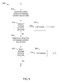
- FIG. 6 shows an example pattern of pressure samples that illustrates an example background noise calculation for a cuff inflation.
- FIG. 7 shows an example of pressure deviations from an average used in a background noise calculation.
- FIGS. 8, 9 and 10 show a flowchart of a method for determining cuff slippage during a blood pressure measurement on an automated blood pressure machine.
- FIG. 11 shows a flow chart of a method for determining a first cuff slippage condition.
- FIG. 12 shows a flow chart of a method for determining a second cuff slippage condition.
- FIG. 13 shows a flow chart of a method for determining a third cuff slippage condition.
- FIG. 14 shows example components of the automatic blood pressure machine of FIG. 1 .
- the present disclosure is directed to systems and methods for determining when cuff slippage occurs during a blood pressure measurement on an automated blood pressure machine.
- the blood pressure machine takes an appropriate action, such as activating an alert or terminating the blood pressure measurement. If the slippage condition is not severe, the blood pressure machine may ignore the slippage condition and continue with the blood pressure measurement.
- Blood pressure is typically measured by two numbers—a systolic blood pressure and a diastolic blood pressure.
- the systolic blood pressure corresponds to a blood pressure when the heart is contracting, corresponding to the maximum arterial pressure during contraction of the left ventricle of the heart.
- the diastolic blood pressure corresponds to a blood pressure when the heart is relaxing, corresponding to the minimum arterial pressure during relaxation.
- blood pressure varies between a maximum (systolic) value and a minimum (diastolic) value.
- a person's blood pressure is commonly expressed in terms of the systolic blood pressure over the diastolic blood pressure, in units of millimeters (mm) of Mercury (Hg), for example 120/80 mmHg.
- a blood pressure measurement comprises an inflation cycle in which the cuff is inflated, followed by a deflation cycle during in which the cuff is deflated.
- the blood pressure machine inflates the cuff to an appropriate pressure above the systolic pressure.
- the blood pressure machine then starts a deflation cycle during which systolic pressure and the diastolic pressure are measured.
- Cuff slippage when it occurs, typically occurs during the inflation cycle when the cuff is expanding. Because the cuff must be securely fastened to the arm of a patient in order to obtain an accurate blood pressure reading, any slippage condition may result in an inaccurate reading, or if the slippage condition is severe, the slippage condition may prevent the blood pressure machine from completing a blood pressure measurement.
- a blood pressure cuff is typically made from a fabric that can be wrapped around the arm of a patient.
- the cuff typically includes a fastening material, such as Velcro, that can be used to secure the cuff to the patient and also permit the patient to easily remove the cuff.
- Velcro is a fastener that typically consists of two strips of fabric—one strip having a plurality of tiny hooks and the other having a plurality of tiny loops. When the strip having the plurality of tiny hooks is placed against the strip with the plurality of tiny loops, the hooks grab onto the loops and fastening occurs. One of the strips can be pulled away from the other to separate the strips.
- fastening material and Velcro are used interchangeably.
- Velcro may be made from a variety of fabrics, such as cotton, Nylon and polyester. Velcro may also be made from plastic or other materials. However, when Velcro ages, it is common for the hooks and loops to wear out so that the fastening action of the Velcro may tend to weaken. When used on a blood pressure cuff, this weakening may cause cuff slippage, particularly during the inflation cycle.
- an appropriate form of action may be taken.
- the form of the action is dependent on the severity of the slippage condition. If the slippage condition is such that a blood pressure for the patient cannot be calculated, the automated blood pressure machine terminates the blood pressure measuring operation. Typically the blood pressure measuring operation is terminated by deflating the cuff. In addition, an alert may be provided for the patient or physician, indicating that the blood pressure measuring operation has been terminated. The alert may take one of several forms, such as an audible alert and a display message on the automatic blood pressure machine. When the slippage condition is not severe enough to interfere with the blood pressure measurement, the automated blood pressure machine may ignore the slippage condition and continue the cuff inflation.
- FIG. 1 shows an example system 100 from which a blood pressure reading can be made.
- the example system 100 includes an example patient 102 and an example automated blood pressure machine 108 .
- An example blood pressure cuff 104 is fastened around the left arm of the patient.
- the blood pressure cuff 104 includes an example fastening material 106 , typically Velcro.
- the example automated blood pressure machine 108 includes a display 110 , controls 112 , a blood pressure processing module 114 and a cuff integrity detection module 116 .
- the example display 110 displays a read out of the blood pressure during cuff inflation and deflation. At the completion of the blood pressure measurement, the blood pressure is displayed, typically as the systolic pressure over the diastolic pressure. In addition, other physiological data may be displayed, for example the patient's heart rate.
- the example controls 112 may include an on/off button, a start button or other similar controls.
- a tube (not shown in FIG. 1 ) connects the blood pressure cuff 104 to the automatic blood pressure processing machine 108 .
- the tube supplies air to the blood pressure cuff 104 , causing the blood pressure cuff 104 to inflate, tightening around the arm of the patient.
- the blood pressure cuff 104 tightens around the arm of the patient, the blood flow through the patient's artery is affected.
- the example blood pressure processing module 114 uses information received from the blood pressure cuff 104 to calculate the blood pressure of the patient. When blood flows through the radial artery under the blood pressure cuff, pressure pulses are created. The blood pressure processing module 114 receives pressure pulse information from the blood pressure cuff 104 . The blood pressure processing module 114 uses the pressure pulse information in conjunction with an algorithm to calculate the systolic and the diastolic blood pressure of the patient.
- the example cuff integrity detection module 116 determines when a cuff slippage condition occurs.
- Cuff slippage may be detected when various patterns of blood pressure readings occur during a cuff inflation. For example, normally during a cuff inflation the blood pressure readings tend to increase until a maximum value is reached. However, during a slippage condition, decreases in blood pressure usually occur. Certain combinations of decreases in blood pressure during a cuff inflation signify a cuff slippage condition, as explained in more detail herein.
- FIG. 2 shows an example pattern 200 of pressure samples during a cuff inflation that signifies one type of cuff slippage condition.
- the example pattern 200 signifies a slippage condition characterized by a 4-point “V”.
- the horizontal axis of pattern 200 shows numbers corresponding to pressure samples.
- the vertical axis of pattern 200 shows numbers corresponding to measured pressure in units of 100 mm of Hg. For example, a value of 5600 represents a pressure sample of 56 mmHg.
- the 4-point “V” corresponds to four specific pressure samples in which the pressure drops and then rises. These four points form a 4-point “V” shape in the example pattern 200 . As discussed herein, a specific mathematical formula is evaluated to determine when the slippage condition characterized by the 4-point “V” shape occurs.
- FIG. 3 shows an example pattern 300 of pressure samples during a cuff inflation that signifies a second type of cuff slippage condition.
- the example pattern 300 signifies a slippage condition characterized by a 5-point “V”.
- the horizontal axis of pattern 300 shows numbers corresponding to pressure samples.
- the vertical axis of pattern 300 shows numbers corresponding to measured pressure in units of 100 mm of Hg.
- the pressure readings shown on the vertical axis have a range from 7450 to 7800, corresponding to a pressure range of 74.5 mmHg to 78 mmHg. This range is an arbitrary range that is different from the range of 54 mmHg to 58 mmHg shown in FIG. 2 .
- slippage condition 1 and slippage condition 2 can occur at any pressure range that occurs above a minimum level of pressure.
- the minimum level of pressure is typically 40 mmHg.
- the 5-point “V” corresponds to five specific pressure samples in which the pressure drops and then rises. These five points form a 5-point “V” shape in the example pattern 300 . As discussed herein, a specific mathematical formula is evaluated to determine when the slippage condition characterized by the 5-point “V” shape occurs.
- FIG. 4 shows an example pattern 400 of pressure samples during a cuff inflation that signifies a third type of cuff slippage condition.
- the example pattern 400 signifies a slippage condition characterized by a sharp drop of pressure that occurs for two successive pressure samples.
- the sharp drop represents a pressure that is more than 2.25 multiplied by the background noise.
- slippage condition 3 can occur during any pressure range above a minimum pressure, typically 40 mmHg. As discussed herein, a specific mathematical formula is evaluated to determine when the slippage condition characterized by pattern 400 occurs.
- FIGS. 5A-5C show mathematical formulas used to evaluate slippage conditions 1 - 3 .
- slippage condition 1 occurs when each of three conditions occur.
- a slope of pressure samples during a cuff inflation must be greater than 0.
- a description of how the slope is determined is provided later herein.
- a pressure three samples previous to the current sample (designated as P(n ⁇ 3), where P(n) is a pressure at the current sample) must be greater than the sum of a pressure two samples previous to the current sample and the product of 1.5 multiplied by a noise level.
- P(n ⁇ 3)>P(n ⁇ 2)+1.5 ⁇ noise This condition is designated as P(n ⁇ 3)>P(n ⁇ 2)+1.5 ⁇ noise.
- the noise level is a number corresponding to a background noise during the cuff inflation, as explained further herein.
- a pressure at the current sample must be greater than the sum of a pressure one sample previous to the current sample and the product of 1.5 multiplied by the background noise. This condition is designated as P(n)>P(n ⁇ 1)+1.5 ⁇ noise.
- slippage condition 2 occurs when each of five conditions occur.
- a slope of pressure samples during a cuff inflation must be greater than zero.
- a pressure four samples previous to the current sample must be greater than the sum of a pressure reading three samples previous to the current sample and the product of 1.5 multiplied by the background noise. This condition is designated as P(n ⁇ 4)>P(n ⁇ 3)+1.5 ⁇ noise.
- a pressure at the current sample must be greater than the sum of a pressure one sample previous to the current sample and the product of 1.5 multiplied by the background noise. This condition is designated as P(n)>P(n ⁇ 1)+1.5 ⁇ noise.
- a pressure two samples previous to the current sample must be less than a pressure three samples previous to the current sample. This condition is designated as P(n ⁇ 2) ⁇ P(n ⁇ 3).
- a pressure two samples previous to the current sample must be less than a pressure one sample previous to the current sample. This condition is designated as P(n ⁇ 2) ⁇ P(n ⁇ 1).
- slippage condition 3 occurs when each of three conditions occur.
- a slope of blood pressure readings during a cuff inflation must be greater than 0.
- a blood pressure reading two samples previous to the current sample must be greater than the sum of a blood pressure reading one sample previous to the current sample and the product of 2.25 multiplied by the background noise. This condition is designated as P(n ⁇ 2)>P(n ⁇ 1)+2.25 ⁇ noise.
- a blood pressure reading one sample previous to the current sample must be greater than the sum of a blood pressure reading at the current sample and the product of 2.25 multiplied by the background noise. This condition is designated as P(n ⁇ 1)>P(n)+2.25 ⁇ noise.
- Cuff slippage condition 3 indicates that a blood pressure drop of greater than the product of 2.25 multiplied by the background noise has occurred for two consecutive pressure samples during the current cuff inflation.
- FIG. 6 shows an example pattern of pressure samples 600 that illustrate an example background noise calculation for a cuff inflation.
- the background noise is derived from seven pressure samples during a cuff inflation. In other examples, more or less than seven samples may be used. Each of the samples occurs above a minimum level of pressure, typically 40 mmHg and each sample occurs when a slope of the pressure readings for the samples is greater than zero.
- the first step in the background noise calculation is to determine a slope of a line 602 corresponding to the seven samples.
- the slope is equal to the highest pressure in the seven samples minus the lowest pressure in the seven samples divided by seven (the number of samples).
- This method of slope calculation is used throughout this disclosure. In other embodiments, other methods for calculating the slope may be used. For example, a method using least squares fit may be used.
- the highest pressure sample for the seven samples typically occurs for the last sample and the lowest pressure for the seven samples typically occurs for the first sample.
- the highest and lowest pressures may occur for samples other than the last sample and the first sample.
- FIG. 7 is an example of seven samples showing deviations in pressure from an example slope line. The example shown in FIG. 7 does not correspond exactly to the pressure samples of FIG. 6 , and is provided for illustration purposes only. As shown in FIG. 7 , example samples 2 and 4 have maximum deviations of 5 below the slope line (represented by 0 on the vertical axis). Example sample 5 has a maximum deviation of 1 above the slope line.
- the background noise is equal to the difference in these maximum deviations or 6 (equal to 1 minus ⁇ 5).
- a number of 6 is used for the noise in the equations used to calculate cuff slippage (as shown in FIGS. 5A-5C ).
- the background noise comes primarily from the operation of a pump used during the cuff inflation. In actual use, there may be slight differences in pump operation for each pump cycle that may cause pressure samples to be above or below the slope. Without reference to the background noise in the equations shown in FIGS. 5A, 5B and 5C , cuff slippage may be mistaken for background noise.
- the background noise is calculated continually during the cuff inflation.
- pressure samples are obtained at a configured sampling rate, for example at a rate of 128 samples per second.
- the background noise is calculated and a determination is made as to whether a slippage condition has occurred.
- the number of samples in the plurality of samples comprises the number of samples used to calculate the background noise plus four additional samples. For the case where seven samples are used to calculate the background noise, the plurality of samples comprises a total of 11 samples.
- a new pressure sample is obtained. For the example of seven samples being used for the background noise calculation plus four additional samples, this new pressure sample and the previous 10 pressure samples form a new plurality of 11 pressure samples that are used to recalculate the background noise and determine whether a slippage condition has occurred. After the background noise is recalculated from the first seven of this new plurality of samples, another determination of whether a slippage condition has occurred is made using this new plurality of 11 pressure samples. In a similar manner, for each succeeding pressure sample obtained during the cuff inflation, a new plurality of 11 pressure samples are used to recalculate the background noise and to determine whether a slippage condition has occurred.
- FIGS. 8, 9 and 10 show a flowchart illustrating an example method 800 for determining cuff slippage during a cuff inflation for a blood pressure measurement on an automated blood pressure machine.
- a pressure sample is taken.
- the pressure reading is one of many samples taken during the cuff inflation.
- An example sample rate is 128 pressure samples per second. In other examples more of fewer samples may be taken per second.
- a minimum value is chosen because patients typically do not have blood pressures below the minimum value, so all samples below this value are ignored.
- a plurality of pressure samples is obtained.
- the plurality of pressure samples includes a sample size of pressure samples needed to determine a background noise level. In examples, a sample size of seven is used. In other examples, more or fewer samples may be used.
- the plurality of pressure samples also includes four additional pressure samples used to determine whether a slippage condition has occurred. For the case where a sample size of seven is used to determine the background noise level, the plurality of pressure samples equals 11 samples.
- a background noise level is determined from the plurality of pressure samples.
- the background noise level is determined by calculating the slope of a line representing a slope for a subset of pressure samples in the plurality of pressure samples.
- the subset of pressure samples corresponds to the first seven pressure samples in the plurality of pressure samples.
- the slope is calculated by subtracting the lowest pressure in the subset from the highest pressure in the subset and dividing by the number of samples in the subset, in this case seven. Once the slope is determined, a maximum deviation of pressure above and below the slope is determined.
- the background noise represents the difference between the maximum deviation above the line and the maximum deviation below the line.
- the first slippage condition corresponds to a 4-point “V” shape of blood pressure readings during the cuff inflation.
- a slip counter is incremented.
- the slip counter is initially set at zero (not shown in FIG. 8 ).
- the value of 10 is an arbitrary value. In other embodiments, a different value may be used.
- the second slippage condition corresponds to a 5-point “V” shape of pressure samples during the cuff inflation.
- the third slippage condition corresponds to two successive pressure drops greater than a pressure threshold during the cuff inflation.
- the pressure threshold for the third slippage condition is 2.25 multiplied by the background noise.
- control returns to operation 806 where a new plurality of pressure samples is obtained.
- a background noise calculation is performed at operation 808 and then the pressure samples are evaluated to determine whether any of the first, second or third slippage conditions are detected.
- slippage conditions may be any combination of the first slippage condition, the second slippage condition and the third slippage condition.
- the way in which slipping is handled is determined by whether a blood pressure reading is able to be calculated from the pressure samples obtained during the cuff inflation.
- the blood pressure reading is displayed on the automated blood pressure machine.
- an operator is alerted that cuff slipping occurred during the cuff inflation.
- the alert may be an audible alert, a visual alert or a combination of both.
- an error code is displayed on the automated blood pressure machine but a blood pressure reading is not provided.
- FIG. 11 shows a flow chart of a method 810 for determining whether the first slippage condition exists.
- the first slippage condition corresponds to a 4-point “V” shape of pressure samples during the cuff inflation.
- a slope of a line corresponding to the plurality of pressure samples from operation 806 is determined.
- the slope is calculated by determining a highest pressure sample and a lowest pressure sample from the first seven samples in the plurality of pressure samples, subtracting the lowest pressure sample from the highest pressure sample and dividing by the sample size, in this example dividing by seven.
- FIG. 12 shows a flow chart of a method 816 for determining whether the second slippage condition exists.
- the second slippage condition corresponds to a 5-point “V” shape of blood pressure readings during the cuff inflation.
- a slope of a line corresponding to the plurality of pressure samples from operation 806 is determined.
- the slope is calculated by determining a highest pressure sample and a lowest pressure sample from the first seven samples in the plurality of pressure samples, subtracting the lowest pressure sample from the highest pressure sample and dividing by the sample size, in this example dividing by seven.
- FIG. 13 shows a flow chart of a method 824 for determining whether the third slippage condition exists.
- the third slippage condition corresponds to a pressure drop of greater than 2.25 multiplied by the background noise for two successive pressure samples during a cuff inflation.
- a slope of a line corresponding to the plurality of pressure samples from operation 806 is determined.
- the slope is calculated by determining a highest pressure sample and a lowest pressure sample from the first seven samples in the plurality of pressure samples, subtracting the lowest pressure sample from the highest pressure sample and dividing by the sample size, in this example dividing by seven.
- the automatic blood pressure machine 108 can include input/output devices, a central processing unit (“CPU”), a data storage device, and a network device.
- CPU central processing unit
- the automatic blood pressure machine 108 typically includes at least one processing unit 1402 and system memory 1404 .
- the system memory 1404 may be volatile (such as RAM), non-volatile (such as ROM, flash memory, etc.) or some combination of the two.
- System memory 1404 typically includes an operating system 1406 suitable for controlling the operation of an automatic blood pressure machine.
- the system memory 1404 may also include one or more software applications 1408 and may include program data.
- the automatic blood pressure machine 108 may have additional features or functionality.
- the automatic blood pressure machine 108 may also include computer readable media.
- Computer readable media can include both computer readable storage media and communication media.
- Computer readable storage media is physical media, such as data storage devices (removable and/or non-removable) including magnetic disks, optical disks, or tape. Such additional storage is illustrated in FIG. 14 by removable storage 1410 and non-removable storage 1412 .
- Computer readable storage media may include volatile and nonvolatile, removable and non-removable media implemented in any method or technology for storage of information, such as computer readable instructions, data structures, program modules, or other data.
- Computer readable storage media can include, but is not limited to, RAM, ROM, EEPROM, flash memory or other memory technology, CD-ROM, digital versatile disks (DVD) or other optical storage, magnetic cassettes, magnetic tape, magnetic disk storage or other magnetic storage devices, or any other medium which can be used to store the desired information and which can be accessed by automatic blood pressure machine 108 . Any such computer readable storage media may be part of the automatic blood pressure machine 108 .
- the automatic blood pressure machine 108 may also contain communication connections 1418 that allow the device to communicate with other computing devices 1420 , such as over a network in a distributed computing environment, for example, an intranet or the Internet.
- Communication connections 1418 are one example of communication media.
- Communication media may typically be embodied by computer readable instructions, data structures, program modules, or other data in a modulated data signal, such as a carrier wave or other transport mechanism, and includes any information delivery media.
- modulated data signal means a signal that has one or more of its characteristics set or changed in such a manner as to encode information in the signal.
- communication media includes wired media such as a wired network or direct-wired connection, and wireless media such as acoustic, RF, infrared and other wireless media.
Abstract
Description
Claims (5)
Priority Applications (1)
| Application Number | Priority Date | Filing Date | Title |
|---|---|---|---|
| US14/539,483 US9480433B2 (en) | 2011-03-21 | 2014-11-12 | Cuff integrity detection during inflation of an automated blood pressure device |
Applications Claiming Priority (2)
| Application Number | Priority Date | Filing Date | Title |
|---|---|---|---|
| US13/052,279 US8911378B2 (en) | 2011-03-21 | 2011-03-21 | Cuff integrity detection during inflation of an automated blood pressure device |
| US14/539,483 US9480433B2 (en) | 2011-03-21 | 2014-11-12 | Cuff integrity detection during inflation of an automated blood pressure device |
Related Parent Applications (1)
| Application Number | Title | Priority Date | Filing Date |
|---|---|---|---|
| US13/052,279 Division US8911378B2 (en) | 2011-03-21 | 2011-03-21 | Cuff integrity detection during inflation of an automated blood pressure device |
Publications (2)
| Publication Number | Publication Date |
|---|---|
| US20150073284A1 US20150073284A1 (en) | 2015-03-12 |
| US9480433B2 true US9480433B2 (en) | 2016-11-01 |
Family
ID=46877920
Family Applications (2)
| Application Number | Title | Priority Date | Filing Date |
|---|---|---|---|
| US13/052,279 Active 2032-09-15 US8911378B2 (en) | 2011-03-21 | 2011-03-21 | Cuff integrity detection during inflation of an automated blood pressure device |
| US14/539,483 Active US9480433B2 (en) | 2011-03-21 | 2014-11-12 | Cuff integrity detection during inflation of an automated blood pressure device |
Family Applications Before (1)
| Application Number | Title | Priority Date | Filing Date |
|---|---|---|---|
| US13/052,279 Active 2032-09-15 US8911378B2 (en) | 2011-03-21 | 2011-03-21 | Cuff integrity detection during inflation of an automated blood pressure device |
Country Status (2)
| Country | Link |
|---|---|
| US (2) | US8911378B2 (en) |
| WO (1) | WO2012129044A2 (en) |
Families Citing this family (5)
| Publication number | Priority date | Publication date | Assignee | Title |
|---|---|---|---|---|
| US8911378B2 (en) | 2011-03-21 | 2014-12-16 | Welch Allyn, Inc. | Cuff integrity detection during inflation of an automated blood pressure device |
| US20120283984A1 (en) * | 2011-05-06 | 2012-11-08 | Taiwan Silicon Microelectronics Co., Ltd. | Automatic control method of inflation |
| CN106441552B (en) * | 2016-09-21 | 2019-12-17 | 广州视源电子科技股份有限公司 | method and system for detecting noise of blood pressure cuff |
| EP3545823A1 (en) | 2018-03-28 | 2019-10-02 | Koninklijke Philips N.V. | Apparatus for use with a wearable cuff |
| EP3909501A1 (en) | 2020-05-11 | 2021-11-17 | Koninklijke Philips N.V. | Apparatus and method for improved blood pressure measurement |
Citations (13)
| Publication number | Priority date | Publication date | Assignee | Title |
|---|---|---|---|---|
| US3348534A (en) * | 1963-11-06 | 1967-10-24 | W W Holland | Automatic sphygmomanometer |
| US3450131A (en) * | 1967-01-09 | 1969-06-17 | Ibm | Blood pressure measuring system with korotkoff sound detector |
| US3905353A (en) | 1974-02-28 | 1975-09-16 | Medical Monitors Inc | Blood pressure apparatus |
| US4295471A (en) | 1979-05-25 | 1981-10-20 | Kaspari William J | Non-invasive vascular waveform transducer and apparatus |
| US4493326A (en) | 1979-10-03 | 1985-01-15 | United States Surgical Corporation | Automatic blood pressure system with servo controlled inflation and deflation |
| US5054494A (en) * | 1989-12-26 | 1991-10-08 | U.S. Medical Corporation | Oscillometric blood pressure device |
| US6765489B1 (en) * | 2002-08-12 | 2004-07-20 | Milwaukee Electronics Corporation | Accelerometer-based infant movement monitoring and alarm device |
| US20060155196A1 (en) * | 2005-01-10 | 2006-07-13 | Maynard Ramsey | Integrated manual mechanical and electronic sphygmomanometer within a single enclosure |
| US20090156946A1 (en) | 2007-12-13 | 2009-06-18 | Welch Allyn, Inc. | Blood pressure motion sensing |
| US20100030302A1 (en) | 2008-07-30 | 2010-02-04 | Medtronic, Inc. | Method for displaying trended data retrieved from a medical device |
| US20110009756A1 (en) * | 2009-07-09 | 2011-01-13 | The General Electric Company | Method, apparatus and computer program for non-invasive blood pressure measurement |
| US20110105927A1 (en) * | 2009-10-30 | 2011-05-05 | Greenhut Saul E | Detection of waveform artifact |
| US8911378B2 (en) | 2011-03-21 | 2014-12-16 | Welch Allyn, Inc. | Cuff integrity detection during inflation of an automated blood pressure device |
Family Cites Families (1)
| Publication number | Priority date | Publication date | Assignee | Title |
|---|---|---|---|---|
| JPH0260633A (en) | 1988-08-26 | 1990-03-01 | Koorin Denshi Kk | Cuff pressure controller for automatic hemadynamometer |
-
2011
- 2011-03-21 US US13/052,279 patent/US8911378B2/en active Active
-
2012
- 2012-03-15 WO PCT/US2012/029204 patent/WO2012129044A2/en active Application Filing
-
2014
- 2014-11-12 US US14/539,483 patent/US9480433B2/en active Active
Patent Citations (13)
| Publication number | Priority date | Publication date | Assignee | Title |
|---|---|---|---|---|
| US3348534A (en) * | 1963-11-06 | 1967-10-24 | W W Holland | Automatic sphygmomanometer |
| US3450131A (en) * | 1967-01-09 | 1969-06-17 | Ibm | Blood pressure measuring system with korotkoff sound detector |
| US3905353A (en) | 1974-02-28 | 1975-09-16 | Medical Monitors Inc | Blood pressure apparatus |
| US4295471A (en) | 1979-05-25 | 1981-10-20 | Kaspari William J | Non-invasive vascular waveform transducer and apparatus |
| US4493326A (en) | 1979-10-03 | 1985-01-15 | United States Surgical Corporation | Automatic blood pressure system with servo controlled inflation and deflation |
| US5054494A (en) * | 1989-12-26 | 1991-10-08 | U.S. Medical Corporation | Oscillometric blood pressure device |
| US6765489B1 (en) * | 2002-08-12 | 2004-07-20 | Milwaukee Electronics Corporation | Accelerometer-based infant movement monitoring and alarm device |
| US20060155196A1 (en) * | 2005-01-10 | 2006-07-13 | Maynard Ramsey | Integrated manual mechanical and electronic sphygmomanometer within a single enclosure |
| US20090156946A1 (en) | 2007-12-13 | 2009-06-18 | Welch Allyn, Inc. | Blood pressure motion sensing |
| US20100030302A1 (en) | 2008-07-30 | 2010-02-04 | Medtronic, Inc. | Method for displaying trended data retrieved from a medical device |
| US20110009756A1 (en) * | 2009-07-09 | 2011-01-13 | The General Electric Company | Method, apparatus and computer program for non-invasive blood pressure measurement |
| US20110105927A1 (en) * | 2009-10-30 | 2011-05-05 | Greenhut Saul E | Detection of waveform artifact |
| US8911378B2 (en) | 2011-03-21 | 2014-12-16 | Welch Allyn, Inc. | Cuff integrity detection during inflation of an automated blood pressure device |
Non-Patent Citations (3)
| Title |
|---|
| International Search Report and Written Opinion in PCT/US2012/029204 mailed Sep. 27, 2012, 8 pages. |
| Townsend et al. (Ambulatory Blood Pressure Monitoring: Coming of Age in Nephrology, Journal of the American Society of Nephrology, 1996, vol. 7:2279-2287). * |
| Wolfram Mathworld, definition of statistical range; see cited references with the document that date to 1962, 1968, and 1995. |
Also Published As
| Publication number | Publication date |
|---|---|
| WO2012129044A2 (en) | 2012-09-27 |
| US8911378B2 (en) | 2014-12-16 |
| WO2012129044A3 (en) | 2012-12-06 |
| US20150073284A1 (en) | 2015-03-12 |
| US20120245478A1 (en) | 2012-09-27 |
Similar Documents
| Publication | Publication Date | Title |
|---|---|---|
| US9480433B2 (en) | Cuff integrity detection during inflation of an automated blood pressure device | |
| US20200214582A1 (en) | Vital sign monitoring apparatuses and methods of using same | |
| US20190069784A1 (en) | Methods And Apparatus For Determining Cuff Blood Pressure | |
| US9017368B2 (en) | Blood pressure calculation method for non-invasive blood pressure measurement apparatus | |
| US8211030B2 (en) | NIBP target inflation pressure automation using derived SPO2 signals | |
| US11406272B2 (en) | Systems and methods for blood pressure measurement | |
| US9044147B2 (en) | Detection of noise during heart beat variation evaluation | |
| US10165984B2 (en) | Configurable vital signs system | |
| JP2001078969A (en) | Calculation of quality in indirect, noninvasive blood pressure determination and its use | |
| US8747328B2 (en) | Continuous blood pressure monitoring | |
| US6346083B1 (en) | Blood-pressure measuring device | |
| US7198604B2 (en) | Method and system for determination of pulse rate | |
| TWI593386B (en) | Device and method for measuring blood pressure and for indication of the ? presence of atrial fibrillation | |
| US20150032012A1 (en) | Non-invasive Blood Pressure Measurement System and Methods of Use | |
| JP2010194202A (en) | Data processor of automatic sphygmomanometer | |
| KR100910591B1 (en) | Blood measuring pressure method | |
| JP2022178053A (en) | Circulating blood amount determination device, circulating blood amount determination program, and circulating blood amount determination method | |
| CN113598740A (en) | Display control method and device for sphygmomanometer | |
| WO2022231890A1 (en) | Learning and predicting temporal profiles of physiological states associated with the administration of commonly used critical care drugs | |
| CN113226163A (en) | Device for use with a wearable cuff | |
| JP2007503858A (en) | Device for detecting arterial pressure | |
| NO862720L (en) | AUTOMATED SYSTOLIC BLOOD PRESSURE MONITOR WITH DATA IMPROVEMENT |
Legal Events
| Date | Code | Title | Description |
|---|---|---|---|
| AS | Assignment |
Owner name: JPMORGAN CHASE BANK, N.A., AS COLLATERAL AGENT, ILLINOIS Free format text: SECURITY INTEREST;ASSIGNORS:ALLEN MEDICAL SYSTEMS, INC.;HILL-ROM SERVICES, INC.;ASPEN SURGICAL PRODUCTS, INC.;AND OTHERS;REEL/FRAME:036582/0123 Effective date: 20150908 Owner name: JPMORGAN CHASE BANK, N.A., AS COLLATERAL AGENT, IL Free format text: SECURITY INTEREST;ASSIGNORS:ALLEN MEDICAL SYSTEMS, INC.;HILL-ROM SERVICES, INC.;ASPEN SURGICAL PRODUCTS, INC.;AND OTHERS;REEL/FRAME:036582/0123 Effective date: 20150908 |
|
| AS | Assignment |
Owner name: JPMORGAN CHASE BANK, N.A., AS COLLATERAL AGENT, ILLINOIS Free format text: SECURITY AGREEMENT;ASSIGNORS:HILL-ROM SERVICES, INC.;ASPEN SURGICAL PRODUCTS, INC.;ALLEN MEDICAL SYSTEMS, INC.;AND OTHERS;REEL/FRAME:040145/0445 Effective date: 20160921 Owner name: JPMORGAN CHASE BANK, N.A., AS COLLATERAL AGENT, IL Free format text: SECURITY AGREEMENT;ASSIGNORS:HILL-ROM SERVICES, INC.;ASPEN SURGICAL PRODUCTS, INC.;ALLEN MEDICAL SYSTEMS, INC.;AND OTHERS;REEL/FRAME:040145/0445 Effective date: 20160921 |
|
| STCF | Information on status: patent grant |
Free format text: PATENTED CASE |
|
| AS | Assignment |
Owner name: HILL-ROM COMPANY, INC., ILLINOIS Free format text: RELEASE BY SECURED PARTY;ASSIGNOR:JPMORGAN CHASE BANK, N.A.;REEL/FRAME:050254/0513 Effective date: 20190830 Owner name: HILL-ROM, INC., ILLINOIS Free format text: RELEASE BY SECURED PARTY;ASSIGNOR:JPMORGAN CHASE BANK, N.A.;REEL/FRAME:050254/0513 Effective date: 20190830 Owner name: VOALTE, INC., FLORIDA Free format text: RELEASE BY SECURED PARTY;ASSIGNOR:JPMORGAN CHASE BANK, N.A.;REEL/FRAME:050254/0513 Effective date: 20190830 Owner name: ANODYNE MEDICAL DEVICE, INC., FLORIDA Free format text: RELEASE BY SECURED PARTY;ASSIGNOR:JPMORGAN CHASE BANK, N.A.;REEL/FRAME:050254/0513 Effective date: 20190830 Owner name: MORTARA INSTRUMENT SERVICES, INC., WISCONSIN Free format text: RELEASE BY SECURED PARTY;ASSIGNOR:JPMORGAN CHASE BANK, N.A.;REEL/FRAME:050254/0513 Effective date: 20190830 Owner name: WELCH ALLYN, INC., NEW YORK Free format text: RELEASE BY SECURED PARTY;ASSIGNOR:JPMORGAN CHASE BANK, N.A.;REEL/FRAME:050254/0513 Effective date: 20190830 Owner name: MORTARA INSTRUMENT, INC., WISCONSIN Free format text: RELEASE BY SECURED PARTY;ASSIGNOR:JPMORGAN CHASE BANK, N.A.;REEL/FRAME:050254/0513 Effective date: 20190830 Owner name: ALLEN MEDICAL SYSTEMS, INC., ILLINOIS Free format text: RELEASE BY SECURED PARTY;ASSIGNOR:JPMORGAN CHASE BANK, N.A.;REEL/FRAME:050254/0513 Effective date: 20190830 Owner name: HILL-ROM SERVICES, INC., ILLINOIS Free format text: RELEASE BY SECURED PARTY;ASSIGNOR:JPMORGAN CHASE BANK, N.A.;REEL/FRAME:050254/0513 Effective date: 20190830 |
|
| AS | Assignment |
Owner name: JPMORGAN CHASE BANK, N.A., ILLINOIS Free format text: SECURITY AGREEMENT;ASSIGNORS:HILL-ROM HOLDINGS, INC.;HILL-ROM, INC.;HILL-ROM SERVICES, INC.;AND OTHERS;REEL/FRAME:050260/0644 Effective date: 20190830 |
|
| MAFP | Maintenance fee payment |
Free format text: PAYMENT OF MAINTENANCE FEE, 4TH YEAR, LARGE ENTITY (ORIGINAL EVENT CODE: M1551); ENTITY STATUS OF PATENT OWNER: LARGE ENTITY Year of fee payment: 4 |
|
| AS | Assignment |
Owner name: HILL-ROM HOLDINGS, INC., ILLINOIS Free format text: RELEASE OF SECURITY INTEREST AT REEL/FRAME 050260/0644;ASSIGNOR:JPMORGAN CHASE BANK, N.A.;REEL/FRAME:058517/0001 Effective date: 20211213 Owner name: BARDY DIAGNOSTICS, INC., ILLINOIS Free format text: RELEASE OF SECURITY INTEREST AT REEL/FRAME 050260/0644;ASSIGNOR:JPMORGAN CHASE BANK, N.A.;REEL/FRAME:058517/0001 Effective date: 20211213 Owner name: VOALTE, INC., FLORIDA Free format text: RELEASE OF SECURITY INTEREST AT REEL/FRAME 050260/0644;ASSIGNOR:JPMORGAN CHASE BANK, N.A.;REEL/FRAME:058517/0001 Effective date: 20211213 Owner name: HILL-ROM, INC., ILLINOIS Free format text: RELEASE OF SECURITY INTEREST AT REEL/FRAME 050260/0644;ASSIGNOR:JPMORGAN CHASE BANK, N.A.;REEL/FRAME:058517/0001 Effective date: 20211213 Owner name: WELCH ALLYN, INC., NEW YORK Free format text: RELEASE OF SECURITY INTEREST AT REEL/FRAME 050260/0644;ASSIGNOR:JPMORGAN CHASE BANK, N.A.;REEL/FRAME:058517/0001 Effective date: 20211213 Owner name: ALLEN MEDICAL SYSTEMS, INC., ILLINOIS Free format text: RELEASE OF SECURITY INTEREST AT REEL/FRAME 050260/0644;ASSIGNOR:JPMORGAN CHASE BANK, N.A.;REEL/FRAME:058517/0001 Effective date: 20211213 Owner name: HILL-ROM SERVICES, INC., ILLINOIS Free format text: RELEASE OF SECURITY INTEREST AT REEL/FRAME 050260/0644;ASSIGNOR:JPMORGAN CHASE BANK, N.A.;REEL/FRAME:058517/0001 Effective date: 20211213 Owner name: BREATHE TECHNOLOGIES, INC., CALIFORNIA Free format text: RELEASE OF SECURITY INTEREST AT REEL/FRAME 050260/0644;ASSIGNOR:JPMORGAN CHASE BANK, N.A.;REEL/FRAME:058517/0001 Effective date: 20211213 |