US9470592B2 - Micromechanical structure having a deformable membrane and a protection against strong deformations - Google Patents

Micromechanical structure having a deformable membrane and a protection against strong deformations Download PDF

Info

Publication number
US9470592B2
US9470592B2 US14/354,113 US201214354113A US9470592B2 US 9470592 B2 US9470592 B2 US 9470592B2 US 201214354113 A US201214354113 A US 201214354113A US 9470592 B2 US9470592 B2 US 9470592B2
Authority
US
United States
Prior art keywords
membrane
micromechanical structure
islets
structure according
lower abutment
Prior art date
Legal status (The legal status is an assumption and is not a legal conclusion. Google has not performed a legal analysis and makes no representation as to the accuracy of the status listed.)
Active, expires
Application number
US14/354,113
Other versions
US20140290375A1 (en
Inventor
Sebastiano Brida
Current Assignee (The listed assignees may be inaccurate. Google has not performed a legal analysis and makes no representation or warranty as to the accuracy of the list.)
Auxitrol SA
Original Assignee
Auxitrol SA
Priority date (The priority date is an assumption and is not a legal conclusion. Google has not performed a legal analysis and makes no representation as to the accuracy of the date listed.)
Filing date
Publication date
Application filed by Auxitrol SA filed Critical Auxitrol SA
Assigned to AUXITROL S.A. reassignment AUXITROL S.A. ASSIGNMENT OF ASSIGNORS INTEREST (SEE DOCUMENT FOR DETAILS). Assignors: BRIDA, SEBASTIANO
Publication of US20140290375A1 publication Critical patent/US20140290375A1/en
Application granted granted Critical
Publication of US9470592B2 publication Critical patent/US9470592B2/en
Active legal-status Critical Current
Adjusted expiration legal-status Critical

Links

Images

Classifications

    • GPHYSICS
    • G01MEASURING; TESTING
    • G01LMEASURING FORCE, STRESS, TORQUE, WORK, MECHANICAL POWER, MECHANICAL EFFICIENCY, OR FLUID PRESSURE
    • G01L9/00Measuring steady of quasi-steady pressure of fluid or fluent solid material by electric or magnetic pressure-sensitive elements; Transmitting or indicating the displacement of mechanical pressure-sensitive elements, used to measure the steady or quasi-steady pressure of a fluid or fluent solid material, by electric or magnetic means
    • G01L9/0041Transmitting or indicating the displacement of flexible diaphragms
    • G01L9/0042Constructional details associated with semiconductive diaphragm sensors, e.g. etching, or constructional details of non-semiconductive diaphragms
    • G01L9/0047Diaphragm with non uniform thickness, e.g. with grooves, bosses or continuously varying thickness
    • BPERFORMING OPERATIONS; TRANSPORTING
    • B81MICROSTRUCTURAL TECHNOLOGY
    • B81BMICROSTRUCTURAL DEVICES OR SYSTEMS, e.g. MICROMECHANICAL DEVICES
    • B81B3/00Devices comprising flexible or deformable elements, e.g. comprising elastic tongues or membranes
    • B81B3/0035Constitution or structural means for controlling the movement of the flexible or deformable elements
    • B81B3/0051For defining the movement, i.e. structures that guide or limit the movement of an element
    • BPERFORMING OPERATIONS; TRANSPORTING
    • B81MICROSTRUCTURAL TECHNOLOGY
    • B81BMICROSTRUCTURAL DEVICES OR SYSTEMS, e.g. MICROMECHANICAL DEVICES
    • B81B3/00Devices comprising flexible or deformable elements, e.g. comprising elastic tongues or membranes
    • B81B3/0097Devices comprising flexible or deformable elements not provided for in groups B81B3/0002 - B81B3/0094
    • GPHYSICS
    • G01MEASURING; TESTING
    • G01LMEASURING FORCE, STRESS, TORQUE, WORK, MECHANICAL POWER, MECHANICAL EFFICIENCY, OR FLUID PRESSURE
    • G01L19/00Details of, or accessories for, apparatus for measuring steady or quasi-steady pressure of a fluent medium insofar as such details or accessories are not special to particular types of pressure gauges
    • G01L19/06Means for preventing overload or deleterious influence of the measured medium on the measuring device or vice versa
    • G01L19/0618Overload protection
    • GPHYSICS
    • G01MEASURING; TESTING
    • G01LMEASURING FORCE, STRESS, TORQUE, WORK, MECHANICAL POWER, MECHANICAL EFFICIENCY, OR FLUID PRESSURE
    • G01L9/00Measuring steady of quasi-steady pressure of fluid or fluent solid material by electric or magnetic pressure-sensitive elements; Transmitting or indicating the displacement of mechanical pressure-sensitive elements, used to measure the steady or quasi-steady pressure of a fluid or fluent solid material, by electric or magnetic means
    • G01L9/0041Transmitting or indicating the displacement of flexible diaphragms
    • G01L9/0042Constructional details associated with semiconductive diaphragm sensors, e.g. etching, or constructional details of non-semiconductive diaphragms
    • G01L9/0048Details about the mounting of the diaphragm to its support or about the diaphragm edges, e.g. notches, round shapes for stress relief
    • BPERFORMING OPERATIONS; TRANSPORTING
    • B81MICROSTRUCTURAL TECHNOLOGY
    • B81BMICROSTRUCTURAL DEVICES OR SYSTEMS, e.g. MICROMECHANICAL DEVICES
    • B81B2201/00Specific applications of microelectromechanical systems
    • B81B2201/02Sensors
    • B81B2201/0264Pressure sensors

Landscapes

  • Physics & Mathematics (AREA)
  • General Physics & Mathematics (AREA)
  • Chemical & Material Sciences (AREA)
  • Analytical Chemistry (AREA)
  • Engineering & Computer Science (AREA)
  • Computer Hardware Design (AREA)
  • Microelectronics & Electronic Packaging (AREA)
  • Measuring Fluid Pressure (AREA)
  • Pressure Sensors (AREA)
  • Micromachines (AREA)

Abstract

The invention relates to a micromechanical structure for measuring or detecting a mechanical quantity or a dynamic quantity, including a deformable membrane (20) and a supporting substrate (10), the membrane (20) including a first portion (20 a) and a second portion (20 b) surrounded by the first portion (20 a), the second portion (20 b) having a thickness that is less than the thickness of the first portion (20 a), the membrane (20) being suspended above the supporting substrate (10) and thus defining a free space (30), said micromechanical structure comprising in addition a lower abutment (21) for limiting the deformations of the membrane (20), said lower abutment (21) being arranged above the supporting substrate (10) and extending into the free space (30) from said supporting substrate (10) toward the membrane (20), characterized in that the lower abutment (21) comprises islets (101-108) that extend into the free space (30) toward the membrane (20) from a flat surface of the lower abutment (21), the islets (101-108) forming a relief structure in such a manner that, in the case of contact between the islets (101-108) and the fine portion (20 b) of the membrane (20), the contact surface between the islets (101-108) and the fine portion (20 b) of the membrane (20) is small with respect to the dimensions of the fine portion (20 b) of the membrane (20).

Description

GENERAL TECHNICAL FIELD
The invention relates to a micromechanical structure intended to measure or detect a mechanical magnitude or a dynamic magnitude.
And it relates more particularly to a micromechanical structure for absolute, relative or differential measuring of a pressure.
STATE OF THE ART
A micromechanical structure for measuring a mechanical or dynamic magnitude such as pressure conventionally includes a deformable membrane and a support substrate, the membrane being suspended above the support substrate and defining a free space.
Uses of these suspended membranes are known.
Capacitive sensors or strain gauges supported by the membrane can measure the deformations undergone by the membrane subject to a contribution of external energy (such as for example pressure applied perpendicularly to the principal plane of the membrane), in observing the modifications of physical properties of the membrane associated to deformations (such as for example a change in electric capacity or internal stresses).
Modifications in energy made to the membrane or force exerted on the membrane can be measured for example in this way and therefore physical magnitudes in a certain medium can be monitored (these are magnitudes of dynamic type, that is, of acceleration type or deceleration type, and/or mechanical type).
Such membranes subjected to strong energies can become fragile, their intrinsic properties can be altered, and their structure can crack or even break.
PRESENTATION OF THE INVENTION
The invention overcomes at least one of the above disadvantages.
To this end the invention proposes a micromechanical structure for measuring or detecting a mechanical magnitude or a dynamic magnitude, including a deformable membrane and a support substrate, the membrane including a first part and a second part enclosed by the first part, the second part having a thickness less than the thickness of the first part, the membrane being suspended above the support substrate defining a free space, said micromechanical structure also including a lower abutment adapted to limit deformations of the membrane, said lower abutment being arranged above the support substrate and extending in the free space from said support substrate towards the membrane, characterized in that the lower abutment includes islets extending into the free space towards the membrane from a flat surface of the lower abutment, the islets forming a relief structure such that in case of contact between the islets and the fine part of the membrane, the contact surface between the islets and the fine part of the membrane is slight relative to the dimensions of the fine part of the membrane.
The invention is advantageously completed by the following characteristics, taken alone or in any technically possible combination:
    • the islets include inclined facets which are oriented according to acute angles greater than zero degrees relative to the flat surface of the lower abutment;
    • the islets are in the form of a mesa;
    • the support substrate also have a central traversing recess;
    • the lower abutment includes a central traversing recess in the form of a cone;
    • it also includes an upper abutment arranged above the membrane;
    • the upper abutment includes recesses distributed around its centre;
    • the support base and the lower abutment are respectively formed from two materials different to each other;
    • the support substrate is made of glass and in which the lower abutment and said support substrate made of glass are connected by anodic sealing or by means of a molecular or covalent bond with or without intermediate layer, or by sintering or by brazing;
    • the support base and the lower abutment are formed from one and the same material;
    • the support base and the abutments are each made of material selected from the following materials: alloys; glass; quartz; alumina; ceramic; Si; SiC; sapphire;
    • the fine part of the membrane has a thickness of between 20 μm and 100 μm;
    • the islets have a height of between 10 μm and 50 μm and a maximal width of between 20 μm and 200 μm.
In addition, the invention proposes a differential pressure sensor including a micromechanical structure according to the initial aspect of the invention.
The invention has many advantages.
The lower abutment protects the membrane from overpressure.
The fact of providing an abutment as an independent element for resistance to overpressure adds the latter to all existing micromechanical structures, without any dimensional change to the deformable membrane and without any modification of the mechanical or thermal behaviour of the structure.
In this way, the resistance of the micromechanical structure is increased without modifying either the structure or the geometry of the suspended membrane. Also, it modifies neither the structure nor the definition of the measuring elements mounted on the membrane and does not encumber the exposed part of the membrane.
Also, the islets minimise stresses due to thermal dilation of oil or another fluid (liquid or gaseous) present in the space between the membrane and the abutment. These islets also allow good circulation of fluid and improve filling of the structure in the case of use as a differential pressure sensor. This is very important in the case of viscous fluid, the islets avoiding the appearance of air bubbles in the fluid, and reducing errors which might be due to poor circulation of fluid, once the structure is filled with said fluid, in the case of use as a differential pressure sensor for example.
The micromechanical structure therefore attains resistance to external stresses without the need to modify the suspended membrane, this micromechanical structure capable of functioning with standard membranes, for example.
PRESENTATION OF FIGURES
Other characteristics and advantages of the invention will emerge from the following description which is purely illustrative and non-limiting and must be considered with respect to the attached drawings, in which:
FIG. 1 illustrates a micromechanical structure according to an embodiment of the invention;
FIG. 2 illustrates a micromechanical structure according to an embodiment of the invention;
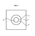
FIG. 3 illustrates a bottom plan view of the micromechanical structure of the invention;
FIG. 4 illustrates a pressure differential sensor including a micromechanical structure according to the invention;
FIG. 5 illustrates a detailed view of part of the micromechanical structure of the invention;
FIGS. 6a and 6b illustrate two views of the lower abutment of the micromechanical structure of the invention.
DETAILED DESCRIPTION OF THE INVENTION
In all figures, similar elements bear identical reference numerals.
A micromechanical structure intended to measure or detect a mechanical magnitude or a dynamic magnitude such as pressure includes a deformable membrane 20 and a support substrate 10.
As is evident in FIGS. 1, 2 and 4, the membrane is arranged above the support substrate 10 to define a free space 30. This free space 30 is intended to be filled by fluid in the case of a micromechanical structure for differential measuring of pressure. In this case, pressure P1 comes from above the structure and pressure P2 comes from below the structure (see FIGS. 1, 2 and 4).
The membrane 20 is intended to support pressure- measurement elements 22, 23 a, 23 b, 24 a, 24 b, 25 a, 25 b, 26 a, 26 b.
The free space 30 is generally formed by micro-machining in an initial substrate. The techniques of micro-machining to form such a free space can for example be chemical etching such as KOH etching at a determined temperature.
Similarly, the membrane is constituted by two distinct parts: a first part 20 a which has a thickness greater than a second part 20 b fine which serves as active element. The second part 20 b is enclosed by the first part 20 a. The part 20 a is that in contact with the support substrate 10, whereas the fine part 20 b is suspended above the free space 30.
The second part 20 b of the membrane 20 has a thickness less than the thickness of the first part 20 a of the membrane.
The thickness of the part 20 b fine is typically of between 20 and 100 m, the value being defined according to the range of the mechanical or dynamic magnitude to be measured.
In this way, the membrane 20, especially its fine part 20 b, can deform under the effect of pressure P1 applied to the latter.
The support substrate 10 can be made of material based on glass, silicon quartz, Pyrex(™), sapphire, alumina, Si, SiC.
The thickness of the support substrate 10 is typically between 500 μm and 2000 μm.
The membrane 20 is connected to the support substrate 10 by anodic sealing or by means of a molecular or atomic bond with or without intermediate layer, or by sintering or by brazing.
The membrane 20 is typically formed from a substrate for example including monocrystalline silicon such as SOI “Silicon On Insulator”) and PSOI “Poly Silicon On Insulator”, sapphire such as SOS “Silicon On Sapphire”, or another material such as SiCOI “SiC on Insulator” or SiC.
The membrane 20 includes an electrically insulating layer 22 such as a SiO2 layer in the case of a membrane 20 made of SOI or PSOI, deposited on its external surface opposite the free space 30. Different materials such as nitrides, oxides, metal layers, mono- and polycrystalline silicon are placed onto this insulating layer 22 so as to form the microstructures 23 a, 23 b, 24 a, 24 b, 25 a, 25 b, 26 a, 26 b. The micro-structures can form strain gauges and serve as elements for measuring the physical magnitude for measuring pressure, for example.
To ensure connections, electric contact zones 25 a, 25 b are also arranged on the membrane 20. These electric contact zones 25 a, 25 b include aluminum, gold, platinum, titanium and tungsten, for example.
To protect the membrane 20 from deformation, in case of overpressure coming from the top of the structure, the micromechanical structure includes a lower abutment 21 limiting deformation of the membrane 20. The lower abutment 21 is arranged above the support substrate 10 and extends into the free space 30 from the support substrate 10 towards the membrane 20.
The lower abutment 21 preferably includes material identical to that of the membrane 20 or made of alloys, sapphire, alumina, ceramic, quartz or glass. It can also include material identical to that of the support substrate 10.
The lower abutment 21 has a general trapezoid shape, the large base being arranged on the substrate 10 support and the small base arranged directly below the membrane 20 in particular under its fine part 20 b, this small base defining a flat surface of the lower abutment 21.
To boost the efficacy of the lower abutment 21 the latter includes (see FIGS. 5 and 6 a and 6 b), on a flat surface, defined especially by the small base of the lower abutment, islets 101, 102, 103, 104, 105, 106, 107, 108 which extend from a flat surface of the lower abutment 21, the flat surface corresponding to the base of the islets.
The islets 101-108 form a relief structure such that in case of contact between the islets 101-108 and the fine part 20 b of the membrane 20, the contact surface between the islets 101-108 and the fine part 20 b of the membrane 20 is slight relative to the dimensions of the fine part 20 b of the membrane 20.
The islets 101-108 advantageously include inclined facets which are oriented according to acute angles greater than zero degrees relative to the flat surface of the lower abutment. They are especially in the form of a mesa.
The resulting islets enable optimal circulation of fluid in the space between the membrane 20 and the lower abutment 21.
Another advantage is that the islets also minimise errors due to the variation in density of fluid (in case of variation in temperatures during use of the micromechanical structure, for example from −50° C. to 180° C.) in the space located between the lower abutment 21 and the membrane 20.
The islets have a height of preferably between 10 μm and 50 μm, and a width at the base of between 20 μm and 200 μm.
Also, the islets are dimensioned so that the fine part of the membrane and the islets are spaced by a distance of between 5 and 30 μm, preferably 10 μm.
The islets are for example obtained by a micro-machining process including steps of photolithography and etching applied to the upper face of the lower abutment 21. The type of etching applied defines the form of the islets (mesa form for humid anisotropic etching of KOH etching type, TMAH form with vertical walls for dry etching of type RIE “Reactive Ion Etching”).
Preferably, the lower abutment including the islets is obtained from a substrate made of silicon in which the islets and the recess (see below) are formed by etching. The pre-formation zones of the islets are protected by a mask preferably made of SiO2+Si3N4, a second mask SiO2+Si3N4 being made after the bond of the lower abutment 21 to the support substrate 10, the bond being preferably made by anodic sealing, the support substrate 10 being made of glass.
As mentioned hereinabove, there is a distance between the lower abutment 21 and the membrane 20. This distance represents the maximal deformation distance of the membrane 20. In this way, greater deformation than this distance supports the membrane 20 against the abutment 21, which prevents overdeformation linked to overpressure. This is in particular against the islets which the membrane 20 supports in the case of overpressure P1 coming from the top of the structure.
By way of advantage, the value of this distance can be selected as a function of the parameters of resistance to deformation of the membrane 20 (dependent especially on its thickness and the material including it) with a threshold distance from which the membrane risks deteriorating.
This is how it is possible to adjust the parameters of the lower abutment 21 as a function of the planned application.
For differential measuring of pressure, the support substrate 10 therefore includes a traversing recess 40 which extends according to a recess 40′ in the lower abutment 21. The recesses 40, 40′ of the support substrate 10 and of the lower abutment 21 are preferably circular.
The recess 40′ of the abutment can be of a diameter identical to or less than the diameter of the recess of the support substrate 10. However a recess is preferred in the form of a cone such as the large diameter of the cone or of the side of the support substrate 10 and reduces while the recess progresses in thickness from the lower abutment 21.
It is noted that without recess 40, the micromechanical structure enables absolute measuring of pressure.
The recess 40 has a geometric form for access of pressure via the support substrate 10. The recess 40 can take the form of a simple cylinder of a diameter generally between 500 μm and 1500 μm, or a more complex form such as for example a double cylinder the diameter of the upper part of which will be less than that of the simple cylinder.
The recesses 40, 40′ of the support substrate 10 and of the lower abutment 21 allow passage of fluids (gas or liquids) and are therefore necessary in the case of a differential or relative sensor to allow transfer of the pressure P2 to the lower part of the membrane 20.
The recesses 40, 40′ in the support substrate 10 of the lower abutment 21 are made by etching by means of an alkaline solution for anisotropic etching (KOH, TMAH, . . . ), preferably conducted in two steps: a first pre-etching step, then final etching after the bond of the lower abutment 21 on the support substrate 10, the bond preferably being made by anodic sealing, the support substrate 10 being made of glass. It is noted that the zones to be spared by etching are protected by a 3D photolithography process of known type based on thick resin (thickness of between 10 μm and 50 μm).
To improve the resistance of the micromechanical structure for differential measuring of the pressure, the latter also includes an upper abutment 60 arranged above the membrane 20 (see FIGS. 2 and 4).
The function of the upper abutment 60 is to mechanically protect the membrane 20 in the event where overpressure comes from below the structure (pressure P2 in FIGS. 2 and 4).
The upper abutment 60 also has one or more recesses 70 (typically four) at its centre and is connected to the rest of the structure via anodic sealing or by means of a molecular or covalent bond with or without intermediate layer, or by sintering or by brazing.
The recesses 70 are pierced in the upper abutment 60 to reduce the effects of capillarity and dilation in temperature after filling by fluid, as well as to make for easier transmission of the pressure P1. Recesses are made at the four corners of the upper abutment 60 to enable the connection to a mechanical housing.
In fact, as illustrated in FIG. 4, the structure described hereinabove is intended to be placed in a housing B and will be immersed in fluid (hatched zones in FIG. 4).
The upper abutment 60 is preferably obtained from a substrate of pierced borosilicate glass.
The upper abutment 60 has overetching zones at the level of the metal tracks and at the four corners of the upper abutment to allow the electrical connection and to make filling by fluid easier. Also, as previously, the zones spared by overetching are protected by a 3D photolithography process of known type based on thick resin.

Claims (15)

The invention claimed is:
1. A micromechanical structure intended to measure or detect a mechanical magnitude or a dynamic magnitude, including a deformable membrane (20) and a support substrate (10), the membrane (20) including a first part (20 a) and a second part (20 b) enclosed by the first part (20 a), the second part (20 b) having a thickness less than the thickness of the first part (20 a), the membrane (20) being suspended above the support substrate (10) and thus defining a free space (30), said micromechanical structure also including a lower abutment (21) adapted to limit the deformations of the membrane (20), said lower abutment (21) being arranged above the support substrate (10) and extending in the free space (30) from said support substrate (10) towards the membrane (20), characterized in that the lower abutment (21) includes islets (101-108) which extend into the free space (30) towards the membrane (20) from a flat surface of the lower abutment (21), the islets (101-108) forming a relief structure such that in the event of contact between the islets (101-108) and the second part (20 b) of the membrane (20), the contact surface between the islets (101-108) and the second part (20 b) of the membrane (20) is small relative to the dimensions of the second part (20 b) of the membrane (20).
2. The micromechanical structure according to claim 1, wherein the islets (101-108) include inclined facets which are oriented according to acute angles greater than zero degrees relative to the flat surface of the lower abutment (21).
3. The micromechanical structure according to any one of claims 1 to 2, wherein the islets are in the form of a mesa.
4. The micromechanical structure according claim 1, wherein the second part (20 b) of the membrane (20) has a thickness of between 20 μm and 100 μm.
5. The micromechanical structure according to claim 1, wherein the islets are dimensioned such that the second part of the membrane and the islets are spaced by a distance of between 5 and 30 μm, preferably 10 μm.
6. The micromechanical structure according to claim 1, wherein the islets (101-108) have a height of between 10 μm and 50 μm and a maximal width, at the base, of between 20 μm and 200 μm.
7. The micromechanical structure according to claim 1, wherein the support substrate (10) also has a central traversing recess (40).
8. The micromechanical structure according to claim 1, wherein the lower abutment (21) includes a central traversing recess (40′) in the form of a cone.
9. The micromechanical structure according to claim 1, also including an upper abutment (60) arranged above the membrane.
10. The micromechanical structure according to claim 9, wherein the upper abutment (60) includes recesses distributed around its centre.
11. The micromechanical structure according to claim 1, wherein the support base (10) and the lower abutment (21) are formed in different materials.
12. The micromechanical structure according to claim 11, wherein the support substrate is made of glass and wherein the abutment and said support substrate made of glass are connected by anodic sealing or by means of a molecular or covalent bond with or without intermediate layer, or by sintering or by brazing.
13. The micromechanical structure according to claim 1, wherein the support base and the lower abutment (21) are formed from one and the same material.
14. The micromechanical structure according to claim 1, characterized in that the support base and the abutment are each made of material selected from the following materials: glass; quartz; alumina; ceramic; alloys; Si; SiC; sapphire.
15. A differential pressure sensor including a micromechanical structure according to claim 1.
US14/354,113 2011-10-26 2012-10-24 Micromechanical structure having a deformable membrane and a protection against strong deformations Active 2033-05-31 US9470592B2 (en)

Applications Claiming Priority (3)

Application Number Priority Date Filing Date Title
FR1159726A FR2982023B1 (en) 2011-10-26 2011-10-26 MICROMECHANICAL STRUCTURE WITH DEFORMABLE MEMBRANE AND PROTECTION AGAINST STRONG DEFORMATIONS
FR1159726 2011-10-26
PCT/EP2012/071000 WO2013060697A1 (en) 2011-10-26 2012-10-24 Micromechanical structure having a deformable membrane and a protection against strong deformations

Publications (2)

Publication Number Publication Date
US20140290375A1 US20140290375A1 (en) 2014-10-02
US9470592B2 true US9470592B2 (en) 2016-10-18

Family

ID=47076229

Family Applications (1)

Application Number Title Priority Date Filing Date
US14/354,113 Active 2033-05-31 US9470592B2 (en) 2011-10-26 2012-10-24 Micromechanical structure having a deformable membrane and a protection against strong deformations

Country Status (9)

Country Link
US (1) US9470592B2 (en)
EP (1) EP2771661B1 (en)
JP (1) JP6022587B2 (en)
CN (1) CN104024816B (en)
BR (1) BR112014009888B1 (en)
CA (1) CA2852847C (en)
ES (1) ES2725557T3 (en)
FR (1) FR2982023B1 (en)
WO (1) WO2013060697A1 (en)

Families Citing this family (11)

* Cited by examiner, † Cited by third party
Publication number Priority date Publication date Assignee Title
FR3007134B1 (en) * 2013-06-17 2018-11-16 Auxitrol S.A. PRESSURE MEASURING SYSTEM DISCRIMINATING FAILURE OF A PRESSURE OR DEPRESSION
US8921957B1 (en) * 2013-10-11 2014-12-30 Robert Bosch Gmbh Method of improving MEMS microphone mechanical stability
US9410861B2 (en) * 2014-03-25 2016-08-09 Honeywell International Inc. Pressure sensor with overpressure protection
US9369804B2 (en) * 2014-07-28 2016-06-14 Robert Bosch Gmbh MEMS membrane overtravel stop
US9890033B2 (en) 2015-04-06 2018-02-13 Honeywell International Inc. Silicon-on-sapphire device with minimal thermal strain preload and enhanced stability at high temperature
US9963340B2 (en) 2015-12-03 2018-05-08 Honeywell International Inc. Pressure sensor die over pressure protection for high over pressure to operating span ratios
US10197462B2 (en) * 2016-05-25 2019-02-05 Honeywell International Inc. Differential pressure sensor full overpressure protection device
US10589983B2 (en) * 2016-09-07 2020-03-17 The Government Of The United States Of America, As Represented By The Secretary Of The Navy Silicon carbide microelectromechanical structure, device, and method
DE102017213354A1 (en) 2017-08-02 2019-02-07 Robert Bosch Gmbh Micromechanical pressure sensor device and corresponding manufacturing method
DE102018222730A1 (en) 2018-12-21 2020-06-25 Robert Bosch Gmbh Micromechanical component and manufacturing method for a micromechanical component
DE102019205349A1 (en) * 2019-04-12 2020-10-15 Robert Bosch Gmbh Micromechanical component for a capacitive sensor or switch device

Citations (4)

* Cited by examiner, † Cited by third party
Publication number Priority date Publication date Assignee Title
US5062302A (en) 1988-04-29 1991-11-05 Schlumberger Industries, Inc. Laminated semiconductor sensor with overpressure protection
FR2859281A1 (en) 2003-09-02 2005-03-04 Auxitrol Sa PROTECTION OF A DEFORMABLE MEMBRANE AGAINST HIGH DEFORMATIONS IN A MICROMECHANICAL STRUCTURE
US20130087864A1 (en) * 2010-01-11 2013-04-11 Elmos Semiconductor Ag Semiconductor component
US20150033878A1 (en) * 2012-03-06 2015-02-05 Centre National De La Recherche Scientifique Laboratoire D'analyse Et D'archit Method for producing a pressure sensor and corresponding sensor

Family Cites Families (5)

* Cited by examiner, † Cited by third party
Publication number Priority date Publication date Assignee Title
JPH06105787B2 (en) * 1983-02-25 1994-12-21 株式会社日立製作所 High pressure resistant pressure sensor
JPH0629819B2 (en) * 1985-12-20 1994-04-20 株式会社東芝 Semiconductor pressure sensor
EP0339981A3 (en) * 1988-04-29 1991-10-09 Schlumberger Industries, Inc. Laminated semiconductor sensor with overpressure protection
US4949581A (en) * 1989-06-15 1990-08-21 Rosemount Inc. Extended measurement capability transmitter having shared overpressure protection means
US5333504A (en) * 1992-09-01 1994-08-02 Rosemount Inc. High overpressure low range pressure sensor

Patent Citations (4)

* Cited by examiner, † Cited by third party
Publication number Priority date Publication date Assignee Title
US5062302A (en) 1988-04-29 1991-11-05 Schlumberger Industries, Inc. Laminated semiconductor sensor with overpressure protection
FR2859281A1 (en) 2003-09-02 2005-03-04 Auxitrol Sa PROTECTION OF A DEFORMABLE MEMBRANE AGAINST HIGH DEFORMATIONS IN A MICROMECHANICAL STRUCTURE
US20130087864A1 (en) * 2010-01-11 2013-04-11 Elmos Semiconductor Ag Semiconductor component
US20150033878A1 (en) * 2012-03-06 2015-02-05 Centre National De La Recherche Scientifique Laboratoire D'analyse Et D'archit Method for producing a pressure sensor and corresponding sensor

Also Published As

Publication number Publication date
JP6022587B2 (en) 2016-11-09
US20140290375A1 (en) 2014-10-02
EP2771661A1 (en) 2014-09-03
JP2014531034A (en) 2014-11-20
FR2982023B1 (en) 2015-03-06
BR112014009888B1 (en) 2020-10-27
CA2852847C (en) 2020-09-15
CN104024816B (en) 2016-03-09
BR112014009888A2 (en) 2017-04-25
ES2725557T3 (en) 2019-09-24
EP2771661B1 (en) 2019-02-20
FR2982023A1 (en) 2013-05-03
CN104024816A (en) 2014-09-03
CA2852847A1 (en) 2013-05-02
WO2013060697A1 (en) 2013-05-02

Similar Documents

Publication Publication Date Title
US9470592B2 (en) Micromechanical structure having a deformable membrane and a protection against strong deformations
JP5568803B2 (en) High temperature medium compatible electrical insulation pressure sensor
EP3174825B1 (en) Suspended membrane for capacitive pressure sensor
CN107894294B (en) Silicon-on-insulator MEMS pressure sensing device with cavity and extended shallow polygonal cavity
US8921952B2 (en) Microelectromechanical system devices having crack resistant membrane structures and methods for the fabrication thereof
US20130214370A1 (en) System and method for minimizing deflection of a membrance of an absolute pressure sensor
US9643836B2 (en) Method for producing a pressure sensor and corresponding sensor
JP6236117B2 (en) Micro mechanical measuring element
US9557346B2 (en) Accelerometer and its fabrication technique
TWI611167B (en) An improved pressure sensor
US20160033349A1 (en) Pressure sensor having cap-defined membrane
US9926187B2 (en) Microelectromechanical system devices having crack resistant membrane structures and methods for the fabrication thereof
EP3617686B1 (en) Pressure sensor device and method of sensing pressure
JP2005195423A (en) Pressure sensor
JP2013148495A (en) Semiconductor sensor
JP2008190961A (en) Piezo-resistive acceleration sensor

Legal Events

Date Code Title Description
AS Assignment

Owner name: AUXITROL S.A., FRANCE

Free format text: ASSIGNMENT OF ASSIGNORS INTEREST;ASSIGNOR:BRIDA, SEBASTIANO;REEL/FRAME:033377/0941

Effective date: 20140610

STCF Information on status: patent grant

Free format text: PATENTED CASE

MAFP Maintenance fee payment

Free format text: PAYMENT OF MAINTENANCE FEE, 4TH YEAR, LARGE ENTITY (ORIGINAL EVENT CODE: M1551); ENTITY STATUS OF PATENT OWNER: LARGE ENTITY

Year of fee payment: 4

MAFP Maintenance fee payment

Free format text: PAYMENT OF MAINTENANCE FEE, 8TH YEAR, LARGE ENTITY (ORIGINAL EVENT CODE: M1552); ENTITY STATUS OF PATENT OWNER: LARGE ENTITY

Year of fee payment: 8