US9468465B2 - Reversible bone coupling device and method - Google Patents
Reversible bone coupling device and method Download PDFInfo
- Publication number
- US9468465B2 US9468465B2 US13/632,337 US201213632337A US9468465B2 US 9468465 B2 US9468465 B2 US 9468465B2 US 201213632337 A US201213632337 A US 201213632337A US 9468465 B2 US9468465 B2 US 9468465B2
- Authority
- US
- United States
- Prior art keywords
- component
- tab
- connector
- opening
- locking mechanism
- Prior art date
- Legal status (The legal status is an assumption and is not a legal conclusion. Google has not performed a legal analysis and makes no representation as to the accuracy of the status listed.)
- Active, expires
Links
- 210000000988 bone and bone Anatomy 0.000 title claims abstract description 122
- 230000008878 coupling Effects 0.000 title claims abstract description 25
- 238000010168 coupling process Methods 0.000 title claims abstract description 25
- 238000005859 coupling reaction Methods 0.000 title claims abstract description 25
- 230000002441 reversible effect Effects 0.000 title claims abstract description 7
- 238000000034 method Methods 0.000 title description 4
- 238000010276 construction Methods 0.000 claims 2
- 239000007787 solid Substances 0.000 claims 1
- 238000003780 insertion Methods 0.000 abstract description 11
- 230000037431 insertion Effects 0.000 abstract description 11
- 230000004927 fusion Effects 0.000 description 66
- 239000007943 implant Substances 0.000 description 10
- 208000000013 Hammer Toe Syndrome Diseases 0.000 description 5
- 238000004873 anchoring Methods 0.000 description 4
- 210000003371 toe Anatomy 0.000 description 4
- 206010061159 Foot deformity Diseases 0.000 description 3
- 230000008901 benefit Effects 0.000 description 3
- 238000010079 rubber tapping Methods 0.000 description 3
- 230000013011 mating Effects 0.000 description 2
- 210000001872 metatarsal bone Anatomy 0.000 description 2
- 238000012986 modification Methods 0.000 description 2
- 230000004048 modification Effects 0.000 description 2
- 230000015572 biosynthetic process Effects 0.000 description 1
- 230000001447 compensatory effect Effects 0.000 description 1
- 230000006835 compression Effects 0.000 description 1
- 238000007906 compression Methods 0.000 description 1
- 238000012937 correction Methods 0.000 description 1
- 238000002513 implantation Methods 0.000 description 1
- 238000004519 manufacturing process Methods 0.000 description 1
- 238000007500 overflow downdraw method Methods 0.000 description 1
- 230000000750 progressive effect Effects 0.000 description 1
- 238000004904 shortening Methods 0.000 description 1
- 238000001356 surgical procedure Methods 0.000 description 1
- 210000002435 tendon Anatomy 0.000 description 1
Images


Classifications
-
- A—HUMAN NECESSITIES
- A61—MEDICAL OR VETERINARY SCIENCE; HYGIENE
- A61B—DIAGNOSIS; SURGERY; IDENTIFICATION
- A61B17/00—Surgical instruments, devices or methods, e.g. tourniquets
- A61B17/56—Surgical instruments or methods for treatment of bones or joints; Devices specially adapted therefor
- A61B17/58—Surgical instruments or methods for treatment of bones or joints; Devices specially adapted therefor for osteosynthesis, e.g. bone plates, screws, setting implements or the like
- A61B17/68—Internal fixation devices, including fasteners and spinal fixators, even if a part thereof projects from the skin
- A61B17/72—Intramedullary pins, nails or other devices
- A61B17/7291—Intramedullary pins, nails or other devices for small bones, e.g. in the foot, ankle, hand or wrist
-
- A—HUMAN NECESSITIES
- A61—MEDICAL OR VETERINARY SCIENCE; HYGIENE
- A61B—DIAGNOSIS; SURGERY; IDENTIFICATION
- A61B17/00—Surgical instruments, devices or methods, e.g. tourniquets
- A61B17/56—Surgical instruments or methods for treatment of bones or joints; Devices specially adapted therefor
- A61B17/58—Surgical instruments or methods for treatment of bones or joints; Devices specially adapted therefor for osteosynthesis, e.g. bone plates, screws, setting implements or the like
- A61B17/68—Internal fixation devices, including fasteners and spinal fixators, even if a part thereof projects from the skin
- A61B17/84—Fasteners therefor or fasteners being internal fixation devices
- A61B17/86—Pins or screws or threaded wires; nuts therefor
- A61B17/8625—Shanks, i.e. parts contacting bone tissue
- A61B17/863—Shanks, i.e. parts contacting bone tissue with thread interrupted or changing its form along shank, other than constant taper
-
- A—HUMAN NECESSITIES
- A61—MEDICAL OR VETERINARY SCIENCE; HYGIENE
- A61B—DIAGNOSIS; SURGERY; IDENTIFICATION
- A61B17/00—Surgical instruments, devices or methods, e.g. tourniquets
- A61B17/56—Surgical instruments or methods for treatment of bones or joints; Devices specially adapted therefor
- A61B17/58—Surgical instruments or methods for treatment of bones or joints; Devices specially adapted therefor for osteosynthesis, e.g. bone plates, screws, setting implements or the like
- A61B17/68—Internal fixation devices, including fasteners and spinal fixators, even if a part thereof projects from the skin
- A61B17/84—Fasteners therefor or fasteners being internal fixation devices
- A61B17/86—Pins or screws or threaded wires; nuts therefor
- A61B17/8685—Pins or screws or threaded wires; nuts therefor comprising multiple separate parts
-
- A—HUMAN NECESSITIES
- A61—MEDICAL OR VETERINARY SCIENCE; HYGIENE
- A61B—DIAGNOSIS; SURGERY; IDENTIFICATION
- A61B17/00—Surgical instruments, devices or methods, e.g. tourniquets
- A61B17/56—Surgical instruments or methods for treatment of bones or joints; Devices specially adapted therefor
- A61B17/58—Surgical instruments or methods for treatment of bones or joints; Devices specially adapted therefor for osteosynthesis, e.g. bone plates, screws, setting implements or the like
- A61B17/68—Internal fixation devices, including fasteners and spinal fixators, even if a part thereof projects from the skin
- A61B17/84—Fasteners therefor or fasteners being internal fixation devices
- A61B17/86—Pins or screws or threaded wires; nuts therefor
-
- A—HUMAN NECESSITIES
- A61—MEDICAL OR VETERINARY SCIENCE; HYGIENE
- A61F—FILTERS IMPLANTABLE INTO BLOOD VESSELS; PROSTHESES; DEVICES PROVIDING PATENCY TO, OR PREVENTING COLLAPSING OF, TUBULAR STRUCTURES OF THE BODY, e.g. STENTS; ORTHOPAEDIC, NURSING OR CONTRACEPTIVE DEVICES; FOMENTATION; TREATMENT OR PROTECTION OF EYES OR EARS; BANDAGES, DRESSINGS OR ABSORBENT PADS; FIRST-AID KITS
- A61F2/00—Filters implantable into blood vessels; Prostheses, i.e. artificial substitutes or replacements for parts of the body; Appliances for connecting them with the body; Devices providing patency to, or preventing collapsing of, tubular structures of the body, e.g. stents
- A61F2/02—Prostheses implantable into the body
- A61F2/30—Joints
- A61F2002/30001—Additional features of subject-matter classified in A61F2/28, A61F2/30 and subgroups thereof
- A61F2002/30316—The prosthesis having different structural features at different locations within the same prosthesis; Connections between prosthetic parts; Special structural features of bone or joint prostheses not otherwise provided for
- A61F2002/30329—Connections or couplings between prosthetic parts, e.g. between modular parts; Connecting elements
- A61F2002/30476—Connections or couplings between prosthetic parts, e.g. between modular parts; Connecting elements locked by an additional locking mechanism
- A61F2002/30481—Connections or couplings between prosthetic parts, e.g. between modular parts; Connecting elements locked by an additional locking mechanism using a locking clip
-
- A—HUMAN NECESSITIES
- A61—MEDICAL OR VETERINARY SCIENCE; HYGIENE
- A61F—FILTERS IMPLANTABLE INTO BLOOD VESSELS; PROSTHESES; DEVICES PROVIDING PATENCY TO, OR PREVENTING COLLAPSING OF, TUBULAR STRUCTURES OF THE BODY, e.g. STENTS; ORTHOPAEDIC, NURSING OR CONTRACEPTIVE DEVICES; FOMENTATION; TREATMENT OR PROTECTION OF EYES OR EARS; BANDAGES, DRESSINGS OR ABSORBENT PADS; FIRST-AID KITS
- A61F2/00—Filters implantable into blood vessels; Prostheses, i.e. artificial substitutes or replacements for parts of the body; Appliances for connecting them with the body; Devices providing patency to, or preventing collapsing of, tubular structures of the body, e.g. stents
- A61F2/02—Prostheses implantable into the body
- A61F2/30—Joints
- A61F2002/30001—Additional features of subject-matter classified in A61F2/28, A61F2/30 and subgroups thereof
- A61F2002/30316—The prosthesis having different structural features at different locations within the same prosthesis; Connections between prosthetic parts; Special structural features of bone or joint prostheses not otherwise provided for
- A61F2002/30329—Connections or couplings between prosthetic parts, e.g. between modular parts; Connecting elements
- A61F2002/30476—Connections or couplings between prosthetic parts, e.g. between modular parts; Connecting elements locked by an additional locking mechanism
- A61F2002/30487—Circumferential cooperating grooves and beads on cooperating lateral surfaces of a mainly longitudinal connection
-
- A—HUMAN NECESSITIES
- A61—MEDICAL OR VETERINARY SCIENCE; HYGIENE
- A61F—FILTERS IMPLANTABLE INTO BLOOD VESSELS; PROSTHESES; DEVICES PROVIDING PATENCY TO, OR PREVENTING COLLAPSING OF, TUBULAR STRUCTURES OF THE BODY, e.g. STENTS; ORTHOPAEDIC, NURSING OR CONTRACEPTIVE DEVICES; FOMENTATION; TREATMENT OR PROTECTION OF EYES OR EARS; BANDAGES, DRESSINGS OR ABSORBENT PADS; FIRST-AID KITS
- A61F2/00—Filters implantable into blood vessels; Prostheses, i.e. artificial substitutes or replacements for parts of the body; Appliances for connecting them with the body; Devices providing patency to, or preventing collapsing of, tubular structures of the body, e.g. stents
- A61F2/02—Prostheses implantable into the body
- A61F2/30—Joints
- A61F2002/30001—Additional features of subject-matter classified in A61F2/28, A61F2/30 and subgroups thereof
- A61F2002/30316—The prosthesis having different structural features at different locations within the same prosthesis; Connections between prosthetic parts; Special structural features of bone or joint prostheses not otherwise provided for
- A61F2002/30329—Connections or couplings between prosthetic parts, e.g. between modular parts; Connecting elements
- A61F2002/30476—Connections or couplings between prosthetic parts, e.g. between modular parts; Connecting elements locked by an additional locking mechanism
- A61F2002/30495—Connections or couplings between prosthetic parts, e.g. between modular parts; Connecting elements locked by an additional locking mechanism using a locking ring
-
- A61F2002/30497—
-
- A—HUMAN NECESSITIES
- A61—MEDICAL OR VETERINARY SCIENCE; HYGIENE
- A61F—FILTERS IMPLANTABLE INTO BLOOD VESSELS; PROSTHESES; DEVICES PROVIDING PATENCY TO, OR PREVENTING COLLAPSING OF, TUBULAR STRUCTURES OF THE BODY, e.g. STENTS; ORTHOPAEDIC, NURSING OR CONTRACEPTIVE DEVICES; FOMENTATION; TREATMENT OR PROTECTION OF EYES OR EARS; BANDAGES, DRESSINGS OR ABSORBENT PADS; FIRST-AID KITS
- A61F2/00—Filters implantable into blood vessels; Prostheses, i.e. artificial substitutes or replacements for parts of the body; Appliances for connecting them with the body; Devices providing patency to, or preventing collapsing of, tubular structures of the body, e.g. stents
- A61F2/02—Prostheses implantable into the body
- A61F2/30—Joints
- A61F2002/30001—Additional features of subject-matter classified in A61F2/28, A61F2/30 and subgroups thereof
- A61F2002/30621—Features concerning the anatomical functioning or articulation of the prosthetic joint
- A61F2002/30622—Implant for fusing a joint or bone material
-
- A—HUMAN NECESSITIES
- A61—MEDICAL OR VETERINARY SCIENCE; HYGIENE
- A61F—FILTERS IMPLANTABLE INTO BLOOD VESSELS; PROSTHESES; DEVICES PROVIDING PATENCY TO, OR PREVENTING COLLAPSING OF, TUBULAR STRUCTURES OF THE BODY, e.g. STENTS; ORTHOPAEDIC, NURSING OR CONTRACEPTIVE DEVICES; FOMENTATION; TREATMENT OR PROTECTION OF EYES OR EARS; BANDAGES, DRESSINGS OR ABSORBENT PADS; FIRST-AID KITS
- A61F2/00—Filters implantable into blood vessels; Prostheses, i.e. artificial substitutes or replacements for parts of the body; Appliances for connecting them with the body; Devices providing patency to, or preventing collapsing of, tubular structures of the body, e.g. stents
- A61F2/02—Prostheses implantable into the body
- A61F2/30—Joints
- A61F2/30767—Special external or bone-contacting surface, e.g. coating for improving bone ingrowth
- A61F2/30771—Special external or bone-contacting surface, e.g. coating for improving bone ingrowth applied in original prostheses, e.g. holes or grooves
- A61F2002/3085—Special external or bone-contacting surface, e.g. coating for improving bone ingrowth applied in original prostheses, e.g. holes or grooves with a threaded, e.g. self-tapping, bone-engaging surface, e.g. external surface
-
- A—HUMAN NECESSITIES
- A61—MEDICAL OR VETERINARY SCIENCE; HYGIENE
- A61F—FILTERS IMPLANTABLE INTO BLOOD VESSELS; PROSTHESES; DEVICES PROVIDING PATENCY TO, OR PREVENTING COLLAPSING OF, TUBULAR STRUCTURES OF THE BODY, e.g. STENTS; ORTHOPAEDIC, NURSING OR CONTRACEPTIVE DEVICES; FOMENTATION; TREATMENT OR PROTECTION OF EYES OR EARS; BANDAGES, DRESSINGS OR ABSORBENT PADS; FIRST-AID KITS
- A61F2/00—Filters implantable into blood vessels; Prostheses, i.e. artificial substitutes or replacements for parts of the body; Appliances for connecting them with the body; Devices providing patency to, or preventing collapsing of, tubular structures of the body, e.g. stents
- A61F2/02—Prostheses implantable into the body
- A61F2/30—Joints
- A61F2/42—Joints for wrists or ankles; for hands, e.g. fingers; for feet, e.g. toes
- A61F2/4225—Joints for wrists or ankles; for hands, e.g. fingers; for feet, e.g. toes for feet, e.g. toes
- A61F2002/4228—Joints for wrists or ankles; for hands, e.g. fingers; for feet, e.g. toes for feet, e.g. toes for interphalangeal joints, i.e. IP joints
-
- A61F2002/423—
-
- A—HUMAN NECESSITIES
- A61—MEDICAL OR VETERINARY SCIENCE; HYGIENE
- A61F—FILTERS IMPLANTABLE INTO BLOOD VESSELS; PROSTHESES; DEVICES PROVIDING PATENCY TO, OR PREVENTING COLLAPSING OF, TUBULAR STRUCTURES OF THE BODY, e.g. STENTS; ORTHOPAEDIC, NURSING OR CONTRACEPTIVE DEVICES; FOMENTATION; TREATMENT OR PROTECTION OF EYES OR EARS; BANDAGES, DRESSINGS OR ABSORBENT PADS; FIRST-AID KITS
- A61F2/00—Filters implantable into blood vessels; Prostheses, i.e. artificial substitutes or replacements for parts of the body; Appliances for connecting them with the body; Devices providing patency to, or preventing collapsing of, tubular structures of the body, e.g. stents
- A61F2/02—Prostheses implantable into the body
- A61F2/30—Joints
- A61F2/42—Joints for wrists or ankles; for hands, e.g. fingers; for feet, e.g. toes
- A61F2/4225—Joints for wrists or ankles; for hands, e.g. fingers; for feet, e.g. toes for feet, e.g. toes
- A61F2002/4233—Joints for wrists or ankles; for hands, e.g. fingers; for feet, e.g. toes for feet, e.g. toes for metatarso-phalangeal joints, i.e. MTP joints
-
- A61F2002/4235—
Definitions
- the present disclosure relates to devices and methods for coupling bones with reversibly engaging bone coupling devices.
- Hammertoe deformity the most common deformity of the lesser toes, is a flexion deformity of the proximal interphalangeal (PIP) joint of the toe, with hyperextension of the metatarsophalangeal (MTP) and distal interphalangeal (DIP) joints.
- Progressive PIP joint flexion deformity typically leads to compensatory hyperextension of the MTP and DIP joints. This makes the PIP joint prominent dorsally. Pain occurs due to rubbing of the prominence against the patient's shoe.
- the deformity is flexible at first but usually becomes fixed over time. When the deformity is flexible, various procedures can be utilized that involve manipulation of the involved tendons. However, when the deformity is fixed, PIP fusion or joint replacement is often required.
- Implants available for this purpose include the Weil-CarverTM Hammertoe Implant (Biomet®, Inc., Warsaw, Ind.), Flexible Digital Implant (Tornier, Inc. Edina, Minn.), SHIP Implant (Sgarlato Labs, Campbell Calif.), Digital Compression Screw (BioPro®, Port Huron Mich.), Smart ToeTM Intramedullary Memory Implant (Memometal Inc., Memphis Tenn.), StayFuseTM Intramedullary Fusion Device (Tornier, Inc. Edina, Minn.), and Pro-Toe (Wright Medical, Arlington Tenn.).
- the latter three implants are used when fusion is desired, since the other implants allow some flexibility of the joint. With all current implants, placement is critical because, when mounted, there is no adjustability following initial implantation in the angle of flexion between the two cut bones to be coupled.
- a reversible bone coupling device comprises a first component and a second component.
- the first component comprises a first elongated stem portion for insertion from a first end longitudinally into a surface of a first bone piece.
- the second component comprises a second elongated stem portion for insertion from a second end longitudinally into a surface of a second bone piece, and a connector extending from a second top for coupling with the first component and locking therein.
- the first component includes a reversibly engaging locking mechanism for disengaging the connector from the first component.
- the reversibly engaging locking mechanism supports incremental locking of the connector of the second component with the first component.
- the reversibly engaging locking mechanism supports disengagement of the connector of the second component from the first component.
- the connector comprises a plurality of grooves, each groove adapted for interlocking with the first component.
- the device promotes fusion of the first bone piece to the second bone piece.
- the first elongated stem portion of the first component comprises a cavity that extends within the first elongated stem from a first top toward the first end, the cavity capable of receiving the connector of the second component.
- the reversibly engaging locking mechanism comprises an integral tab for mating with any of a plurality of grooves of the connector.
- the reversibly engaging locking mechanism comprises an integral deflection means.
- the integral deflection means is at least one of an integral tab and an inline deformed tab.
- the first elongated stem portion of the first component comprises an opening and an internal lock ring, the opening capable of receiving the connector of the second component.
- the connector comprises a plurality of notches for mating with the internal lock ring of the first elongated stem portion.
- the internal lock ring comprises a plurality of bosses for anchoring the internal lock ring in the first component to prevent rotation.
- the first elongated stem portion further comprises a cavity defined by a wall, a closed distal end, and an open proximal end, and the cavity receives the connector.
- the connector is capable of being adjustably positioned in relation to the second top when coupling with the first component.
- each of the first elongated stem portion and the second elongated stem portion are at least one of cylindrical and conical.
- At least one of the first elongated stem portion and the second elongated stem portion is a spiraling thread.
- the spiraling thread is a continuous spiraling thread.
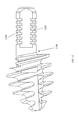
- FIG. 1 illustrates a bone fusion device in accordance with an embodiment of the present disclosure.
- FIG. 2 illustrates a bone fusion device after fusion of the male and female component in accordance with an embodiment of the present disclosure.
- FIG. 3 illustrates a side view of a male component of a bone fusion device in accordance with an embodiment of the present disclosure.
- FIG. 4 illustrates another side view of a male component of a bone fusion device in accordance with an embodiment of the present disclosure.
- FIG. 5 illustrates a perspective view of a male component of a bone fusion device in accordance with an embodiment of the present disclosure.
- FIG. 6 illustrates a perspective and cut-away view of a female component of a bone fusion device in accordance with an embodiment of the present disclosure.
- FIG. 7 illustrates a view of the opening of a cavity of a female component of a bone fusion device in accordance with an embodiment of the present disclosure.
- FIGS. 8 a - c illustrate perspective views of a ring of a reversibly engaging locking mechanism of a bone fusion device in accordance with an embodiment of the present disclosure.
- FIG. 9 illustrates a view of the opening of a cavity of a female component of a bone fusion device with a partially disengaged ring of a reversibly engaging locking mechanism in accordance with an embodiment of the present disclosure.
- FIG. 10 illustrates a perspective view of a female component of a bone fusion device including an opening for receiving a ring of a reversibly engaging locking mechanism.
- FIG. 11 illustrates a bone fusion device in accordance with an embodiment of the present disclosure.
- FIG. 12 illustrates a male component of a bone fusion device in accordance with an embodiment of the present disclosure.
- FIG. 13 illustrates another male component of a bone fusion device in accordance with an embodiment of the present disclosure.
- FIG. 14 illustrates a female component of a bone fusion device in accordance with an embodiment of the present disclosure.
- FIG. 15 illustrates a cross-sectional view of a bone fusion device after coupling of a female component and a male component in accordance with an embodiment of the present disclosure.
- FIG. 16 illustrates a bone fusion device after fusion of a female component and a male component in accordance with an embodiment of the present disclosure.
- FIG. 17 illustrates a view into a cavity of a female component of a bone fusion device in accordance with an embodiment of the present disclosure.
- FIG. 18 illustrates a perspective view of a female component of a bone fusion device in accordance with an embodiment of the present disclosure.
- FIG. 19 illustrates a cross-sectional view of a female component of a bone fusion device in accordance with an embodiment of the present disclosure.
- FIG. 20 illustrates another integral deflection means comprising an inline deformed tab of a reversibly engaging locking mechanism for locking with a groove of a connector of a male component in accordance with an embodiment of the present disclosure.
- FIG. 21 illustrates a bone fusion device in accordance with an embodiment of the present disclosure.
- FIG. 22 illustrates a female component of a bone fusion device in accordance with an embodiment of the present disclosure.
- FIG. 23 illustrates a cross-sectional view of a female component of a bone fusion device in accordance with an embodiment of the present disclosure.
- FIG. 24 illustrates a cross-sectional view of a bone fusion device where the male component has been inserted into the female component, in accordance with an embodiment of the present disclosure.
- FIG. 25 illustrates an elevated magnified perspective view illustrating a ring, in accordance with an embodiment of the present disclosure.
- FIG. 26 illustrates an elevated side view perspective illustrating a male component, in accordance with an embodiment of the present disclosure.
- a reversible bone coupling device facilitates adjustment of an angle between two bones to be coupled, as well as being reversibly engaging to assist in corrections of the coupling of the two bones.
- the reversible bone coupling device comprises a first component and a second component.
- the first component comprises a first elongated stem portion comprising a first end and a first top opposite the first end.
- the first elongated stem portion is suitable for insertion from the first end longitudinally into a surface of a first bone piece of a bone.
- the second component comprises a second elongated stem portion comprising a second end and a second top.
- the second elongated stem portion is suitable for insertion from the second end longitudinally into a surface of a second bone piece of the bone.
- the second component further comprises a connector extending from the second top.
- the connector is capable of coupling with the first component and locking therewith to couple the first component and the second component.
- the first component further comprises a reversibly engaging locking mechanism that locks the connector, and facilitates unlocking of the connector to allow adjustment of the fusion between the first component and the second component.
- the first component is a female component and the second component is a male component.
- the first elongated stem portion of the female component may comprise an opening that extends axially from the first top toward the first end.
- the connector may comprise an elongated shaft, a proximal end, a top of shaft near the proximal end, and a distal end, where the connector is capable of insertion into the opening in the first elongated stem portion and locking therein to couple the male component and the female component.
- the device is useful for coupling any two bone pieces, and by way of the reversibly engaging mechanism, the connector may be reversed to adjust the position of the connector or remove the connector entirely in situations where adjustment of the device may be necessary or contemplated to further assist in coupling or fusing cut surfaces of bones.
- the device is adaptable to any bone size, shape, or configuration of any patient.
- the device is particularly useful in coupling or fusing cut surfaces of bones such as cut ends of fingers or toes. This may facilitate the treatment of hammertoe, claw toe, mallet toe, or curly toe.
- the first elongated stem portion is suitable for insertion from the first end longitudinally into a cut surface of a resected phalanx, metatarsal or metacarpal, or a cut diaphyhsis
- the second elongated stem portion is suitable for insertion from the second end longitudinally into a cut surface of a resected phalanx, metatarsal or metacarpal, or a cut diaphyhsis.
- a bone fixation or fusion method and system are described.
- a first component of a bone fusion device is inserted into a first bone piece.
- a second component of a bone fusion device is inserted into a second bone piece.
- a connector of the second component is inserted into a cavity of the first component.
- the connector is locked within the cavity of the first component by a reversibly engaging locking mechanism to facilitate formation of a fused bone. If necessary, the reversibly engaging locking mechanism may be adjusted to allow the connector and corresponding second component to be longitudinally adjusted or removed from the first component to facilitate adjustments or modifications during or after surgery.
- FIG. 1 illustrates a bone fusion device in accordance with an embodiment of the present disclosure.
- Bone fusion device 10 includes a female component 20 and a male component 30 .
- Female component 20 is an elongated stem comprising a first end 21 , a first top 22 , and a cavity 29 .
- Female component 20 also includes a spiraling thread 24 on the exterior, suitable for screwing female component 20 into a bone or bone piece.
- Male component 30 is an elongated stem comprising a second end 31 and a second top 32 .
- Male component 30 further includes a connector 40 extending from the second top 32 .
- connector 40 may be configured to be adjustably attached to the elongated stem of the male component 30 , thus supporting the effective lengthening or shortening of the male component 30 .
- Male component 30 also includes a spiraling thread 34 on the exterior, suitable for screwing male component 30 into a bone or bone piece.
- Female component 20 and male component 30 can independently be cylindrical or conical, or any combination thereof. Where the illustrated embodiments show spiraling threads as means to anchor a male component or female component to a bone, alternate anchoring means may be used. Where present, the spiraling threads can be of any type known in the art for screwing into a bone. Thus, in some embodiments, the spiraling thread is a continuous spiraling thread. In other embodiments, the spiraling thread allows self-tapping and/or self-threading.
- the spiraling threads may be continuous. In yet another embodiment, the spiraling threads may spiral in the same direction so that when the device is screwed into opposing bone surfaces and coupled, the opposing pitch of the threads in the bone prevents the device from unscrewing.
- the embodiments described herein are not limited to any particular pitch of one rotation of the continuous spiraling thread.
- the pitch may be 5 mm or greater, 4 mm, 3 mm, 2 mm, 1 mm, or any distance in between the aforementioned distances.
- Connector 40 may comprise grooves for interlocking with a reversibly engaging locking mechanism of female component 20 .
- reversibly engaging locking mechanism 50 as shown in FIG. 6
- reversibly engaging locking mechanism locks the connector of the male component within the female component such that the bone pieces that the male component and the female component are screwed into become coupled or fused as a bone fusion.
- FIG. 2 illustrates a bone fusion device after coupling of the male and female component in accordance with an embodiment of the present disclosure.
- FIG. 2 shows bone fusion device 10 after connector 40 of male component 30 has been inserted into cavity 29 of female component 20 .
- Connector 40 is held and locked within the female component by the reversibly engaging locking mechanism 50 .
- FIG. 3 illustrates a side view of a male component of a bone fusion device in accordance with an embodiment of the present disclosure.
- Male component 30 includes connector 40 , which comprises a plurality of grooves 41 for engaging with a reversibly engaging locking mechanism to lock connector 40 within a female component to couple the male component and the female component.
- FIG. 4 illustrates another side view of a male component of a bone fusion device in accordance with an embodiment of the present disclosure.
- the plurality of grooves 41 may be on two sides of connector 40 .
- FIG. 5 illustrates a perspective view of a male component of a bone fusion device in accordance with an embodiment of the present disclosure.
- FIG. 6 illustrates a perspective and cut-away view of a female component of a bone fusion device in accordance with an embodiment of the present disclosure.
- the inside of cavity 29 is viewable.
- a plurality of lobes 51 and a ring 52 both of which are a part of reversibly engaging locking mechanism 50 .
- Ring 52 rests within a slot 55 that is sized for receiving ring 52 .
- the plurality of lobes 51 is located at the opening of cavity 29 .
- the plurality of lobes 51 are configured such that any one or two of the lobes may receive a corresponding boss 53 of ring 52 to prevent rotation of ring 52 .
- FIG. 6 illustrates a cut-away view, only three lobes 51 are viewable and one boss 53 of ring 52 . Additionally, a portion of a chamfer 54 of ring 52 is viewable. Chamfer 54 protrudes so that when connector 40 is inserted into cavity 29 , chamfer 54 engages with any of grooves 41 to lock connector 40 within female component 20 .
- Ring 52 allows rotational unlocking of connector 40 from female component 20 . Ring 52 may be rotated to unlock chamfer 54 from a groove of connector 40 , and allow connector 40 to be pulled outwards from cavity 29 . This facilitates complete removal of connector 40 from cavity 29 or adjustment such that a different groove of connector 40 can be caused to engage with chamfer 54 to lock connector 40 within female component 20 in a new position.
- FIG. 7 illustrates a view of the opening of a cavity of a female component of a bone fusion device looking from the first end 21 toward the first top 22 , in accordance with an embodiment of the present disclosure.
- Cavity 29 includes six lobes 51 , and ring 52 which rests within a slot within the cavity.
- Ring 52 includes two bosses 53 , each of which is engaged with a corresponding lobe 51 to hold ring 52 in place within cavity 29 . More specifically, lobes 51 anchor bosses 53 of a ring 52 to prevent rotation of ring 52 .
- Chamfer 54 shown in FIG. 7 , protrudes from ring 52 in order to engage with grooves of a connector.
- the cavity may include any number of lobes depending on the size of the lobes and the cavity, provided that the lobes of sufficient size to secure two or more bosses to prevent rotation of the ring.
- the ring may have two or more bosses provided that they are of sufficient size to remain secured in the lobes so as to prevent rotation of the ring.
- FIGS. 8 a - c illustrate perspective views of a ring of a reversibly engaging locking mechanism of a bone fusion device in accordance with an embodiment of the present disclosure.
- FIG. 9 illustrates a view of the opening of a cavity 29 of a female component of a bone fusion device with a partially disengaged ring 52 of a reversibly engaging locking mechanism in accordance with an embodiment of the present disclosure.
- Ring 52 as shown is partially disengaged since only one boss 92 is currently engaged with a lobe 94 .
- FIG. 9 is meant to illustrate how ring 52 is inserted into cavity 29 .
- Ring 52 is inserted into cavity 29 through an opening (not shown) on a side of female component 20 . Once one end of ring 52 is inserted, a boss, such as boss 92 of that end may be engaged with a lobe 94 .
- FIG. 10 illustrates a perspective view of a female component of a bone fusion device including an opening for receiving a ring of a reversibly engaging locking mechanism.
- FIG. 10 shows an opening 1002 of female component 20 for receiving ring 52 .
- FIG. 11 illustrates a bone fusion device in accordance with an embodiment of the present disclosure.
- Bone fusion device 1110 includes a female component 1120 and a male component 1130 .
- Female component 1120 is an elongated stem comprising a first end 1121 , a first top 1122 , and a cavity 1129 .
- Female component 1120 also includes a spiraling thread 1124 on the exterior, suitable for screwing female component 1120 into a bone or bone piece.
- Male component 1130 is an elongated stem comprising a second end 1131 and a second top 1132 .
- Male component 1130 further includes a connector 1140 extending from second top 1132 .
- Male component 1130 also includes a spiraling thread 1134 on the exterior, suitable for screwing male component 1130 into a bone or bone piece.
- Female component 1120 and male component 1130 can independently be cylindrical or conical, or any combination thereof. Where the illustrated embodiments show spiraling threads as means to anchor a male component or female component to a bone, alternate anchoring means may be used. Where present, the spiraling threads can be of any type known in the art for screwing into a bone. Thus, in some embodiments, the spiraling thread is a continuous spiraling thread. In other embodiments, the spiraling thread allows self-tapping and/or self-threading.
- the spiraling threads may be continuous. In yet another embodiment, the spiraling threads may spiral in the same direction so that when the device is screwed into opposing bone surfaces and coupled, the opposing pitch of the threads in the bone prevents the device from unscrewing.
- the embodiments described herein are not limited to any particular pitch of one rotation of the continuous spiraling thread.
- the pitch may be 5 mm or greater, 4 mm, 3 mm, 2 mm, 1 mm, or any distance in between the aforementioned distances.
- Connector 1140 may comprise grooves 1142 for interlocking with a reversibly engaging locking mechanism 1150 of female component 1120 .
- reversibly engaging locking mechanism 1150 locks the connector of the male component within the female component such that the bone pieces that the male component and the female component are screwed into become coupled or fused as a bone fusion.
- Reversibly engaging locking mechanism 1150 may be an integral deflection means such as an integral tab that has been cut into a wall of female component 1120 . The integral tab may be deflected inward or be a machined tab protruding inside the main diameter of cavity 1129 .
- integral tab fits within grooves of connector 1140 in order to lock connector 1140 in place within female component 1120 .
- Axial force applied to the integral tab will unlock the integral tab from a groove of connector 1140 .
- integral tab may be bent inwards or outwards at a specific angle to release connector 1140 . Once released, connector 1140 may be adjusted within cavity 1129 of female component 1120 , or connector 1140 may be removed entirely.
- FIG. 12 illustrates a male component of a bone fusion device in accordance with an embodiment of the present disclosure.
- Male component 1130 includes a plurality of grooves 1220 .
- the plurality of grooves 1220 are configured as segmental recesses, which support rotational unlocking of connector 1140 from reversibly engaging locking mechanism 1150 which comprises an integral tab.
- FIG. 13 illustrates another male component of a bone fusion device in accordance with an embodiment of the present disclosure.
- Male component 1300 includes a plurality of grooves 1320 .
- the plurality of grooves 1320 are full radial grooves that may lock with an integral tab of reversibly engaging locking mechanism, and unlock when axial force is applied to reversibly engaging locking mechanism.
- FIG. 14 illustrates a female component of a bone fusion device in accordance with an embodiment of the present disclosure.
- Female component 1120 is shown.
- On a wall of female component 1120 is an integral tab of reversibly engaging locking mechanism 1150 , which has been cut into the wall of female component 1120 .
- FIG. 16 illustrates a bone fusion device after coupling of a female component and a male component in accordance with an embodiment of the present disclosure.
- Bone fusion device 1110 is shown by FIG. 16 in a position where both female component 1120 and male component 1130 are coupled.
- FIG. 17 illustrates a view into a cavity of a female component of a bone fusion device in accordance with an embodiment of the present disclosure.
- a portion of integral tab 1510 is visible.
- This portion of integral tab 1510 of the reversibly engaging locking mechanism is a portion that engages with a groove of the connector to lock the connector in place within cavity 1129 .
- FIG. 18 illustrates a perspective view of a female component of a bone fusion device in accordance with an embodiment of the present disclosure.
- FIG. 18 provides a view of integral tab 1510 within cavity 1129 of female component 1120 .
- FIG. 19 illustrates a cross-sectional view of a female component of a bone fusion device in accordance with an embodiment of the present disclosure.
- the cross-sectional view provides a view of an inside of cavity 1129 , as well as a full view of integral tab 1510 of a reversibly engaging locking mechanism, which is used to hold a connector in place within cavity 1129 .
- FIG. 20 illustrates another integral deflection means comprising an inline deformed tab of a reversibly engaging locking mechanism for locking with a groove of a connector of a male component in accordance with an embodiment of the present disclosure.
- Male component 2030 is in a form of a conical shape, with a connector 2040 including a plurality of grooves. Each of the grooves of connector 2040 may engage with a reversibly engaging locking mechanism of a female component 2020 of bone fusion device 2010 .
- Reversibly engaging locking mechanism includes an inline deformed tab 2051 for engaging with grooves of connector 2040 .
- Inline deformed tab 2051 may be bent inwards, and due to a combination of driving slot and tab, may result in easier manufacture.
- FIG. 21 illustrates a bone fusion device in accordance with an embodiment of the present disclosure.
- Bone fusion device 2110 includes a female component 2120 and a male component 2130 .
- Female component 2120 is an elongated stem comprising a first end 2121 , a first top 2122 , and a cavity 2129 .
- Female component 2120 also includes a spiraling thread 2124 on the exterior, suitable for screwing female component 2120 into a bone or bone piece.
- Male component 2130 is an elongated stem comprising a second end 2131 and a second top 2132 .
- Male component 2130 further includes a connector 2140 extending from second top 2132 .
- Male component 2130 also includes a spiraling thread 2134 on the exterior, suitable for screwing male component 2130 into a bone or bone piece.
- Female component 2120 and male component 2130 can independently be cylindrical or conical, or any combination thereof. Where the illustrated embodiments show spiraling threads as means to anchor a male component or female component to a bone, alternate anchoring means may be used. Where present, the spiraling threads can be of any type known in the art for screwing into a bone. Thus, in some embodiments, the spiraling thread is a continuous spiraling thread. In other embodiments, the spiraling thread allows self-tapping and/or self-threading.
- the spiraling threads may be continuous. In yet another embodiment, the spiraling threads may spiral in the same direction so that when the device is screwed into opposing bone surfaces and coupled, the opposing pitch of the threads in the bone prevents the device from unscrewing.
- the embodiments described herein are not limited to any particular pitch of one rotation of the continuous spiraling thread.
- the pitch may be 5 mm or greater, 4 mm, 3 mm, 2 mm, 1 mm, or any distance in between the aforementioned distances.
- Connector 2140 may comprise a plurality of notches 2142 for interlocking with a reversibly engaging locking mechanism of female component 2120 .
- the reversibly engaging locking mechanism may include a ring that can expand to allow insertion of connector 2140 . After passing the ring, the notches 2142 may engage with the reversibly engaging locking mechanism which locks connector 2140 of the male component 2130 within the female component 2120 such that the bone pieces that the male component 2130 and the female component 2120 are screwed into become coupled or fused as a bone fusion.
- connector 2140 Removal of connector 2140 from female component 2120 is facilitated by the ring of the reversibly engaging locking mechanism which acts as a friction axial lock which responds to a predetermined amount of longitudinal force applied to connector 2140 which causes connector 2140 to be removeable or adjustable from within cavity 2129 .
- FIG. 22 illustrates a female component of a bone fusion device in accordance with an embodiment of the present disclosure.
- FIG. 22 depicts female component 2120 of an embodiment of the bone fusion device.
- FIG. 23 illustrates a cross-sectional view of a female component of a bone fusion device in accordance with an embodiment of the present disclosure.
- Female component 2120 as illustrated, includes a reversibly engaging locking mechanism.
- Reversibly engaging locking mechanism resides within cavity 2129 and includes a ring 2151 and a plurality of grooves 2152 for receiving connector 2140 .
- Ring 2151 acts as a friction axial lock which can interact with the notches of connector 2140 . This facilitates incremental insertion of connector 2140 .
- ring 2151 also supports incremental removal or adjustment of connector 2140 .
- Ring 2151 itself may comprise one or more ridges for catching or engaging with the notches of connector 2140 as connector 2140 is inserted or removed.
- FIG. 24 illustrates a cross-sectional view of a bone fusion device where the male component has been inserted into the female component, in accordance with an embodiment of the present disclosure.
- connector 2140 of male component 2130 has been inserted into cavity 2129 of female component 2120 .
- the connector 2140 has engaged with grooves 2152 of the reversibly engaging locking mechanism.
- the notches 2142 of connector 2140 have engaged with ring 2151 and are thus locked in place.
- Connector 2140 may be inserted longitudinally such that the notches 2142 engage with ring 2151 which acts as a friction axial lock.
- Increasing amounts of compressive force applied to end 2131 of male component 2130 causes connector 2140 to be implanted deeper within female component 2120 .
- a greater amount of longitudinal force applied outwards would cause removal or outwards movement of connector 2140 in a direction outwards from cavity 2129 in which connector 2140 may be implanted.
- FIG. 26 illustrates an elevated side view perspective illustrating a male component, in accordance with an embodiment of the present disclosure.
- Connector 2140 is hexagonal, with notches for engaging the ring 2151 of FIG. 25 , which supports adjustment within, or removal from, female component 2120 .
- Connector 2140 's hexagonal shape further provides rotational stability of the male and female components, 2130 , 2120 , with respect to each other when coupled via the connector 2140 .
Abstract
Description
Claims (22)
Priority Applications (6)
| Application Number | Priority Date | Filing Date | Title |
|---|---|---|---|
| US13/632,337 US9468465B2 (en) | 2009-02-19 | 2012-10-01 | Reversible bone coupling device and method |
| EP17185419.3A EP3269319B1 (en) | 2012-10-01 | 2013-10-01 | Reversible bone coupling device |
| DE202013011213.1U DE202013011213U1 (en) | 2012-10-01 | 2013-10-01 | Reversible bone coupling device |
| EP13186873.9A EP2712563B1 (en) | 2012-10-01 | 2013-10-01 | Reversible bone coupling device |
| US29/499,535 USD738504S1 (en) | 2012-10-01 | 2014-08-15 | Hammertoe implant |
| US15/295,562 US10639083B2 (en) | 2009-02-19 | 2016-10-17 | Reversible bone coupling device and method |
Applications Claiming Priority (3)
| Application Number | Priority Date | Filing Date | Title |
|---|---|---|---|
| US15390709P | 2009-02-19 | 2009-02-19 | |
| US12/709,426 US8715325B2 (en) | 2009-02-19 | 2010-02-19 | Bone joining apparatus and method |
| US13/632,337 US9468465B2 (en) | 2009-02-19 | 2012-10-01 | Reversible bone coupling device and method |
Related Parent Applications (1)
| Application Number | Title | Priority Date | Filing Date |
|---|---|---|---|
| US12/709,426 Continuation-In-Part US8715325B2 (en) | 2009-02-19 | 2010-02-19 | Bone joining apparatus and method |
Related Child Applications (2)
| Application Number | Title | Priority Date | Filing Date |
|---|---|---|---|
| US29/499,535 Continuation USD738504S1 (en) | 2012-10-01 | 2014-08-15 | Hammertoe implant |
| US15/295,562 Continuation US10639083B2 (en) | 2009-02-19 | 2016-10-17 | Reversible bone coupling device and method |
Publications (2)
| Publication Number | Publication Date |
|---|---|
| US20130030475A1 US20130030475A1 (en) | 2013-01-31 |
| US9468465B2 true US9468465B2 (en) | 2016-10-18 |
Family
ID=47597842
Family Applications (2)
| Application Number | Title | Priority Date | Filing Date |
|---|---|---|---|
| US13/632,337 Active 2032-04-06 US9468465B2 (en) | 2009-02-19 | 2012-10-01 | Reversible bone coupling device and method |
| US15/295,562 Active 2031-06-25 US10639083B2 (en) | 2009-02-19 | 2016-10-17 | Reversible bone coupling device and method |
Family Applications After (1)
| Application Number | Title | Priority Date | Filing Date |
|---|---|---|---|
| US15/295,562 Active 2031-06-25 US10639083B2 (en) | 2009-02-19 | 2016-10-17 | Reversible bone coupling device and method |
Country Status (1)
| Country | Link |
|---|---|
| US (2) | US9468465B2 (en) |
Cited By (1)
| Publication number | Priority date | Publication date | Assignee | Title |
|---|---|---|---|---|
| DE112019005322T5 (en) | 2018-10-26 | 2022-01-13 | Nextremity Solutions, Inc. | BONE COUPLING DEVICE AND METHOD |
Families Citing this family (21)
| Publication number | Priority date | Publication date | Assignee | Title |
|---|---|---|---|---|
| EP2200540A4 (en) * | 2007-08-02 | 2011-03-02 | Proactive Orthopedic Llc | Fixation and alignment device and method used in orthopaedic surgery |
| US8882816B2 (en) | 2007-08-02 | 2014-11-11 | Proactive Orthopedics, Llc | Fixation and alignment device and method used in orthopaedic surgery |
| BRPI1008295A2 (en) | 2009-02-19 | 2016-03-15 | Nextremity Solutions Llc | bone joint apparatus and method |
| US9724140B2 (en) | 2010-06-02 | 2017-08-08 | Wright Medical Technology, Inc. | Tapered, cylindrical cruciform hammer toe implant and method |
| US8608785B2 (en) | 2010-06-02 | 2013-12-17 | Wright Medical Technology, Inc. | Hammer toe implant with expansion portion for retrograde approach |
| US9072564B2 (en) | 2010-06-02 | 2015-07-07 | Wright Medical Technology, Inc. | Hammer toe implant and method |
| US9498273B2 (en) | 2010-06-02 | 2016-11-22 | Wright Medical Technology, Inc. | Orthopedic implant kit |
| US9101399B2 (en) | 2011-12-29 | 2015-08-11 | Proactive Orthopedics, Llc | Anchoring systems and methods for surgery |
| US10631994B2 (en) | 2012-10-12 | 2020-04-28 | Smith & Nephew, Inc. | Fusion Implant |
| US20140188239A1 (en) * | 2012-12-27 | 2014-07-03 | Wright Medical Technology, Inc. | Double thread hammertoe compression device |
| US8945232B2 (en) | 2012-12-31 | 2015-02-03 | Wright Medical Technology, Inc. | Ball and socket implants for correction of hammer toes and claw toes |
| US20140343616A1 (en) * | 2013-04-22 | 2014-11-20 | Daniel Sellers | Arthrodesis compression device |
| US9517098B2 (en) | 2013-07-03 | 2016-12-13 | Biomet Manufacturing, Llc | Bone fusion device |
| US9724139B2 (en) | 2013-10-01 | 2017-08-08 | Wright Medical Technology, Inc. | Hammer toe implant and method |
| US9474561B2 (en) | 2013-11-19 | 2016-10-25 | Wright Medical Technology, Inc. | Two-wire technique for installing hammertoe implant |
| US9498266B2 (en) | 2014-02-12 | 2016-11-22 | Wright Medical Technology, Inc. | Intramedullary implant, system, and method for inserting an implant into a bone |
| US9545274B2 (en) | 2014-02-12 | 2017-01-17 | Wright Medical Technology, Inc. | Intramedullary implant, system, and method for inserting an implant into a bone |
| CA2887570C (en) | 2014-09-18 | 2018-05-01 | Wright Medical Technology, Inc. | Hammertoe implant and instrument |
| JP6438033B2 (en) | 2014-12-19 | 2018-12-12 | ライト メディカル テクノロジー インコーポレイテッドWright Medical Technology, Inc. | Intramedullary implant |
| EP3582701A4 (en) | 2017-02-20 | 2021-04-21 | Paragon 28, Inc. | Implants, devices, instruments, systems and methods of forming and implanting |
| FR3065368B1 (en) * | 2017-04-25 | 2021-12-24 | In2Bones | ARTHRODESIS IMPLANT AND SURGICAL KIT COMPRISING SUCH AN IMPLANT |
Citations (64)
| Publication number | Priority date | Publication date | Assignee | Title |
|---|---|---|---|---|
| US3991425A (en) | 1975-11-20 | 1976-11-16 | Minnesota Mining And Manufacturing Company | Prosthetic bone joint devices |
| GB1582974A (en) | 1975-11-06 | 1981-01-21 | Schuett & Grundei Sanitaet | Finger joint endoprostheses |
| US4246662A (en) | 1979-06-07 | 1981-01-27 | Zimmer Usa, Inc. | Prosthetic joint |
| US4304011A (en) | 1980-08-25 | 1981-12-08 | Whelan Iii Edward J | Semi-constrained metacarpophalangeal prosthesis |
| GB2126097A (en) | 1982-07-05 | 1984-03-21 | Howmedica | Prosthetic finger joint |
| USD277784S (en) | 1982-06-25 | 1985-02-26 | Sutter Biomedical, Inc. | Lesser toe metatarsal phalangeal implant |
| US4908031A (en) | 1989-07-27 | 1990-03-13 | Dow Corning Wright | Toe implant |
| US5037440A (en) | 1989-06-06 | 1991-08-06 | Koenig Implant, Inc. | Orthopedic toe implant |
| US5062851A (en) | 1989-04-25 | 1991-11-05 | Medevelop Ab | Anchoring element for supporting a joint mechanism of a finger or other reconstructed joint |
| US5129903A (en) | 1988-06-18 | 1992-07-14 | Luhr Hans Georg | Bone plate |
| US5167661A (en) | 1989-09-27 | 1992-12-01 | Jaquet Orthopedie S.A. | Device for articulation and relative locking of two pieces |
| US5207712A (en) | 1992-05-07 | 1993-05-04 | Michael Cohen | Absorbable joint implants for the lesser digits and metatarsal phalangeal joints in the surgical correction of the foot |
| WO1993009728A1 (en) | 1991-11-16 | 1993-05-27 | Michael Francis Rosa | Universal joint for dental abutment implant |
| US5290314A (en) | 1992-01-31 | 1994-03-01 | Sulzer Medizinaltechnik Ag | Finger joint prosthesis made of metal |
| US5417692A (en) | 1994-01-04 | 1995-05-23 | Goble; E. Marlowe | Bone fixation and fusion system |
| US5443467A (en) | 1993-03-10 | 1995-08-22 | Biedermann Motech Gmbh | Bone screw |
| WO1996005784A1 (en) | 1994-08-19 | 1996-02-29 | Moje Hans Juergen | Unguided endoprosthesis for small limbs |
| WO1997016137A1 (en) | 1995-10-31 | 1997-05-09 | Sarkisian James S | Prosthetic joint and method of manufacture |
| US5683466A (en) | 1996-03-26 | 1997-11-04 | Vitale; Glenn C. | Joint surface replacement system |
| US5725581A (en) | 1992-10-29 | 1998-03-10 | Medevelop Ab | Anchoring element supporting prostheses or a joint mechanism for a reconstructed joint |
| US5810822A (en) | 1994-04-27 | 1998-09-22 | Mortier; Jean-Pierre | Apparatus for correcting long bone deformation |
| US5810591A (en) | 1994-12-04 | 1998-09-22 | Huber; Peter | Link between a dental implant and an artificial tooth and method for producing |
| US5827285A (en) | 1996-12-12 | 1998-10-27 | Bramlet; Dale G. | Multipiece interfragmentary fixation assembly |
| US5919193A (en) | 1996-03-14 | 1999-07-06 | Slavitt; Jerome A. | Method and kit for surgically correcting malformations in digits of a finger or toe |
| US6099571A (en) | 1997-07-16 | 2000-08-08 | Knapp; John G. | Joint prosthesis |
| EP0831757B1 (en) | 1995-06-13 | 2001-11-28 | Bionx Implants Oy | Joint prosthesis |
| US6383223B1 (en) | 1997-06-18 | 2002-05-07 | BAEHLER ANDRé | Endoprosthesis for a joint, especially a finger, toe or wrist joint |
| US6413260B1 (en) | 1999-08-17 | 2002-07-02 | Pioneer Laboratories, Inc. | Bone connector system |
| US6454808B1 (en) | 1998-01-28 | 2002-09-24 | M-E-System Inc. | Finger joint prosthesis |
| US6458134B1 (en) | 1999-08-17 | 2002-10-01 | Pioneer Laboratories, Inc. | Bone connector system with anti-rotational feature |
| US6517543B1 (en) | 1999-08-17 | 2003-02-11 | Pioneer Laboratories, Inc. | Bone connector system with anti-rotational feature |
| US6602293B1 (en) | 1996-11-01 | 2003-08-05 | The Johns Hopkins University | Polymeric composite orthopedic implant |
| US20040127900A1 (en) | 2002-12-31 | 2004-07-01 | Konieczynski David D. | Resilient bone plate and screw system allowing bi-directional assembly |
| US20040220678A1 (en) | 2003-04-29 | 2004-11-04 | Chow Shew Ping | Prosthetic device and method for total joint replacement in small joint arthroplasty |
| US6852113B2 (en) | 2001-12-14 | 2005-02-08 | Orthopaedic Designs, Llc | Internal osteotomy fixation device |
| US20050043732A1 (en) | 2003-08-18 | 2005-02-24 | Dalton Brian E. | Cervical compression plate assembly |
| US20050113830A1 (en) | 2003-11-24 | 2005-05-26 | Alan Rezach | Grommet assembly |
| US20050192587A1 (en) | 2004-02-27 | 2005-09-01 | Lim Roy K. | Rod reducer |
| US6964994B1 (en) | 1999-07-22 | 2005-11-15 | Max-Planck-Gesellschaft Zur Forderung Der Wissenschaften E.V. | Polyreactions in non-aqueous miniemulsions |
| US20060052878A1 (en) | 2004-08-18 | 2006-03-09 | Reinhold Schmieding | Modular joint replacement implant with hydrogel surface |
| US20060074492A1 (en) | 2004-09-09 | 2006-04-06 | Theo Frey | Endoprosthesis for a metatarsophalangeal joint |
| US7041106B1 (en) | 2001-06-15 | 2006-05-09 | Biomet, Inc. | Interphalangeal fusion pin |
| US20060195087A1 (en) | 2005-02-02 | 2006-08-31 | Ronald Sacher | Adjustable length implant |
| US7214226B2 (en) | 2002-07-24 | 2007-05-08 | Nas Spine, Inc. | Compressible fixation apparatus for spinal surgery |
| WO2007109752A2 (en) | 2006-03-22 | 2007-09-27 | Ascension Orthopedics, Inc. | Prosthetic implant and assembly method |
| US7291175B1 (en) | 2005-01-06 | 2007-11-06 | David J Gordon | Metatarsal phalangeal implant with locking screw |
| US7297165B1 (en) | 1999-11-02 | 2007-11-20 | Ardemed Innovations Limited | Joint prostheses |
| US20080045963A1 (en) | 2006-08-21 | 2008-02-21 | Abdou M S | Bone screw systems and methods of use |
| US20080065224A1 (en) | 2005-02-16 | 2008-03-13 | Astor Reigstad | Joint Prosthesis and Use of Screw Tool for Positioning Members Thereof |
| US20080097611A1 (en) | 2006-09-26 | 2008-04-24 | Depuy Spine, Inc. | Nucleus anti-expulsion devices and methods |
| US20090157121A1 (en) | 2007-12-13 | 2009-06-18 | Harris Peter M | Dynamic anterior vertebral plate |
| US7611526B2 (en) | 2004-08-03 | 2009-11-03 | K Spine, Inc. | Spinous process reinforcement device and method |
| US7635364B2 (en) | 2004-12-01 | 2009-12-22 | Synthes Usa, Llc | Unidirectional translation system for bone fixation |
| US20100036439A1 (en) | 2008-08-07 | 2010-02-11 | Abraham Lavi | Small joint fusion implant |
| US20100121325A1 (en) | 2008-06-24 | 2010-05-13 | Jeff Tyber | Hybrid intramedullary fixation assembly and method of use |
| US20100256638A1 (en) | 2008-06-24 | 2010-10-07 | Jeff Tyber | Intraosseous intramedullary fixation assembly and method of use |
| US20110054545A1 (en) | 2009-08-28 | 2011-03-03 | Lloyd Champagne | Distal interphalangeal fusion device and method of use |
| US20110082508A1 (en) | 2009-10-02 | 2011-04-07 | Jason M. Hiatt | Apparatus and Method for Use in the Treatment of Hammertoe |
| US20110118739A1 (en) | 2008-06-24 | 2011-05-19 | Jeff Tyber | Intramedullary fixation assembly and method of use |
| US20110125153A1 (en) | 2008-06-24 | 2011-05-26 | Jeff Tyber | Intramedullary fixation assembly and method of use |
| US8100983B2 (en) | 2008-11-25 | 2012-01-24 | Schulte Robert C | Intra-osseus fusion system |
| US8303589B2 (en) | 2008-06-24 | 2012-11-06 | Extremity Medical Llc | Fixation system, an intramedullary fixation assembly and method of use |
| US8313487B2 (en) | 2008-06-24 | 2012-11-20 | Extremity Medical Llc | Fixation system, an intramedullary fixation assembly and method of use |
| US8328806B2 (en) | 2008-06-24 | 2012-12-11 | Extremity Medical, Llc | Fixation system, an intramedullary fixation assembly and method of use |
Family Cites Families (11)
| Publication number | Priority date | Publication date | Assignee | Title |
|---|---|---|---|---|
| FR2620932A1 (en) | 1987-09-28 | 1989-03-31 | Saffar Philippe | PROSTHESIS OF METACARPO-PHALANGIAN OR INTERPHALANGIAN ARTICULATION OF FINGERS |
| US5219903A (en) | 1988-10-15 | 1993-06-15 | Sumitomo Chemical Company, Ltd. | Pigment master batch for filler-containing polypropylene compositions |
| FR2679440A1 (en) | 1991-07-24 | 1993-01-29 | Hades | JOINT PROSTHESIS, IN PARTICULAR TRAPEZO-METACARPIAN AND DIGITAL. |
| DE19949890A1 (en) | 1999-10-15 | 2001-06-07 | Peter Copf | Prosthetic top ankle joint has two parts, two joint surfaces, anchor sections with anchor elements |
| JP4266141B2 (en) | 2003-08-28 | 2009-05-20 | 伊藤 薫 | Artificial finger joint |
| US7951198B2 (en) | 2005-05-10 | 2011-05-31 | Acumed Llc | Bone connector with pivotable joint |
| EP2200540A4 (en) | 2007-08-02 | 2011-03-02 | Proactive Orthopedic Llc | Fixation and alignment device and method used in orthopaedic surgery |
| BRPI1008295A2 (en) | 2009-02-19 | 2016-03-15 | Nextremity Solutions Llc | bone joint apparatus and method |
| US20120065692A1 (en) | 2010-09-10 | 2012-03-15 | Lloyd Champagne | Proximal interphalangeal fusion device |
| US20130123862A1 (en) | 2010-10-10 | 2013-05-16 | Gregory Anderson | Arthrodesis implant and buttressing apparatus and method |
| US8764842B2 (en) | 2012-05-31 | 2014-07-01 | Michael Graham | Interphalangeal joint implant methods and apparatus |
-
2012
- 2012-10-01 US US13/632,337 patent/US9468465B2/en active Active
-
2016
- 2016-10-17 US US15/295,562 patent/US10639083B2/en active Active
Patent Citations (66)
| Publication number | Priority date | Publication date | Assignee | Title |
|---|---|---|---|---|
| GB1582974A (en) | 1975-11-06 | 1981-01-21 | Schuett & Grundei Sanitaet | Finger joint endoprostheses |
| US3991425A (en) | 1975-11-20 | 1976-11-16 | Minnesota Mining And Manufacturing Company | Prosthetic bone joint devices |
| US4246662A (en) | 1979-06-07 | 1981-01-27 | Zimmer Usa, Inc. | Prosthetic joint |
| US4304011A (en) | 1980-08-25 | 1981-12-08 | Whelan Iii Edward J | Semi-constrained metacarpophalangeal prosthesis |
| USD277784S (en) | 1982-06-25 | 1985-02-26 | Sutter Biomedical, Inc. | Lesser toe metatarsal phalangeal implant |
| GB2126097A (en) | 1982-07-05 | 1984-03-21 | Howmedica | Prosthetic finger joint |
| US5129903A (en) | 1988-06-18 | 1992-07-14 | Luhr Hans Georg | Bone plate |
| US5062851A (en) | 1989-04-25 | 1991-11-05 | Medevelop Ab | Anchoring element for supporting a joint mechanism of a finger or other reconstructed joint |
| US5037440A (en) | 1989-06-06 | 1991-08-06 | Koenig Implant, Inc. | Orthopedic toe implant |
| US4908031A (en) | 1989-07-27 | 1990-03-13 | Dow Corning Wright | Toe implant |
| US5167661A (en) | 1989-09-27 | 1992-12-01 | Jaquet Orthopedie S.A. | Device for articulation and relative locking of two pieces |
| WO1993009728A1 (en) | 1991-11-16 | 1993-05-27 | Michael Francis Rosa | Universal joint for dental abutment implant |
| US5290314A (en) | 1992-01-31 | 1994-03-01 | Sulzer Medizinaltechnik Ag | Finger joint prosthesis made of metal |
| US5207712A (en) | 1992-05-07 | 1993-05-04 | Michael Cohen | Absorbable joint implants for the lesser digits and metatarsal phalangeal joints in the surgical correction of the foot |
| US5725581A (en) | 1992-10-29 | 1998-03-10 | Medevelop Ab | Anchoring element supporting prostheses or a joint mechanism for a reconstructed joint |
| US5443467A (en) | 1993-03-10 | 1995-08-22 | Biedermann Motech Gmbh | Bone screw |
| US5417692A (en) | 1994-01-04 | 1995-05-23 | Goble; E. Marlowe | Bone fixation and fusion system |
| US5810822A (en) | 1994-04-27 | 1998-09-22 | Mortier; Jean-Pierre | Apparatus for correcting long bone deformation |
| WO1996005784A1 (en) | 1994-08-19 | 1996-02-29 | Moje Hans Juergen | Unguided endoprosthesis for small limbs |
| US5810591A (en) | 1994-12-04 | 1998-09-22 | Huber; Peter | Link between a dental implant and an artificial tooth and method for producing |
| EP0831757B1 (en) | 1995-06-13 | 2001-11-28 | Bionx Implants Oy | Joint prosthesis |
| WO1997016137A1 (en) | 1995-10-31 | 1997-05-09 | Sarkisian James S | Prosthetic joint and method of manufacture |
| US5919193A (en) | 1996-03-14 | 1999-07-06 | Slavitt; Jerome A. | Method and kit for surgically correcting malformations in digits of a finger or toe |
| US5683466A (en) | 1996-03-26 | 1997-11-04 | Vitale; Glenn C. | Joint surface replacement system |
| US6602293B1 (en) | 1996-11-01 | 2003-08-05 | The Johns Hopkins University | Polymeric composite orthopedic implant |
| US5827285A (en) | 1996-12-12 | 1998-10-27 | Bramlet; Dale G. | Multipiece interfragmentary fixation assembly |
| US6383223B1 (en) | 1997-06-18 | 2002-05-07 | BAEHLER ANDRé | Endoprosthesis for a joint, especially a finger, toe or wrist joint |
| US6099571A (en) | 1997-07-16 | 2000-08-08 | Knapp; John G. | Joint prosthesis |
| US6284001B1 (en) | 1997-07-16 | 2001-09-04 | John G. Knapp | Joint prosthesis |
| US6454808B1 (en) | 1998-01-28 | 2002-09-24 | M-E-System Inc. | Finger joint prosthesis |
| US6964994B1 (en) | 1999-07-22 | 2005-11-15 | Max-Planck-Gesellschaft Zur Forderung Der Wissenschaften E.V. | Polyreactions in non-aqueous miniemulsions |
| US6517543B1 (en) | 1999-08-17 | 2003-02-11 | Pioneer Laboratories, Inc. | Bone connector system with anti-rotational feature |
| US6413260B1 (en) | 1999-08-17 | 2002-07-02 | Pioneer Laboratories, Inc. | Bone connector system |
| US6458134B1 (en) | 1999-08-17 | 2002-10-01 | Pioneer Laboratories, Inc. | Bone connector system with anti-rotational feature |
| US7297165B1 (en) | 1999-11-02 | 2007-11-20 | Ardemed Innovations Limited | Joint prostheses |
| US7041106B1 (en) | 2001-06-15 | 2006-05-09 | Biomet, Inc. | Interphalangeal fusion pin |
| US6852113B2 (en) | 2001-12-14 | 2005-02-08 | Orthopaedic Designs, Llc | Internal osteotomy fixation device |
| US7214226B2 (en) | 2002-07-24 | 2007-05-08 | Nas Spine, Inc. | Compressible fixation apparatus for spinal surgery |
| US20040127900A1 (en) | 2002-12-31 | 2004-07-01 | Konieczynski David D. | Resilient bone plate and screw system allowing bi-directional assembly |
| US20040220678A1 (en) | 2003-04-29 | 2004-11-04 | Chow Shew Ping | Prosthetic device and method for total joint replacement in small joint arthroplasty |
| US20050043732A1 (en) | 2003-08-18 | 2005-02-24 | Dalton Brian E. | Cervical compression plate assembly |
| US20050113830A1 (en) | 2003-11-24 | 2005-05-26 | Alan Rezach | Grommet assembly |
| US20050192587A1 (en) | 2004-02-27 | 2005-09-01 | Lim Roy K. | Rod reducer |
| US7611526B2 (en) | 2004-08-03 | 2009-11-03 | K Spine, Inc. | Spinous process reinforcement device and method |
| US20060052878A1 (en) | 2004-08-18 | 2006-03-09 | Reinhold Schmieding | Modular joint replacement implant with hydrogel surface |
| US20060074492A1 (en) | 2004-09-09 | 2006-04-06 | Theo Frey | Endoprosthesis for a metatarsophalangeal joint |
| US7635364B2 (en) | 2004-12-01 | 2009-12-22 | Synthes Usa, Llc | Unidirectional translation system for bone fixation |
| US7291175B1 (en) | 2005-01-06 | 2007-11-06 | David J Gordon | Metatarsal phalangeal implant with locking screw |
| US20060195087A1 (en) | 2005-02-02 | 2006-08-31 | Ronald Sacher | Adjustable length implant |
| US20080065224A1 (en) | 2005-02-16 | 2008-03-13 | Astor Reigstad | Joint Prosthesis and Use of Screw Tool for Positioning Members Thereof |
| US7837738B2 (en) | 2005-02-16 | 2010-11-23 | Swemac Orthopaedics Ab | Joint prosthesis and use of screw tool for positioning members thereof |
| WO2007109752A2 (en) | 2006-03-22 | 2007-09-27 | Ascension Orthopedics, Inc. | Prosthetic implant and assembly method |
| US20080045963A1 (en) | 2006-08-21 | 2008-02-21 | Abdou M S | Bone screw systems and methods of use |
| US20080097611A1 (en) | 2006-09-26 | 2008-04-24 | Depuy Spine, Inc. | Nucleus anti-expulsion devices and methods |
| US20090157121A1 (en) | 2007-12-13 | 2009-06-18 | Harris Peter M | Dynamic anterior vertebral plate |
| US8303589B2 (en) | 2008-06-24 | 2012-11-06 | Extremity Medical Llc | Fixation system, an intramedullary fixation assembly and method of use |
| US20100121325A1 (en) | 2008-06-24 | 2010-05-13 | Jeff Tyber | Hybrid intramedullary fixation assembly and method of use |
| US20100256638A1 (en) | 2008-06-24 | 2010-10-07 | Jeff Tyber | Intraosseous intramedullary fixation assembly and method of use |
| US8328806B2 (en) | 2008-06-24 | 2012-12-11 | Extremity Medical, Llc | Fixation system, an intramedullary fixation assembly and method of use |
| US8313487B2 (en) | 2008-06-24 | 2012-11-20 | Extremity Medical Llc | Fixation system, an intramedullary fixation assembly and method of use |
| US20110118739A1 (en) | 2008-06-24 | 2011-05-19 | Jeff Tyber | Intramedullary fixation assembly and method of use |
| US20110125153A1 (en) | 2008-06-24 | 2011-05-26 | Jeff Tyber | Intramedullary fixation assembly and method of use |
| US20100036439A1 (en) | 2008-08-07 | 2010-02-11 | Abraham Lavi | Small joint fusion implant |
| US8100983B2 (en) | 2008-11-25 | 2012-01-24 | Schulte Robert C | Intra-osseus fusion system |
| US20110054545A1 (en) | 2009-08-28 | 2011-03-03 | Lloyd Champagne | Distal interphalangeal fusion device and method of use |
| US20110082508A1 (en) | 2009-10-02 | 2011-04-07 | Jason M. Hiatt | Apparatus and Method for Use in the Treatment of Hammertoe |
Non-Patent Citations (11)
| Title |
|---|
| Caterini, et al., "Arthrodesis of the Toe Joints with an INtramedullary Cannulated Screw for Correction of Hammertoe Deformity," Foot & Ankle International, 2004, pp. 256-261, vol. 25, No. 4. |
| DE 19949890, Published Jun. 7, 2001, abstract only in English, downloaded from espacenet.com, 2 pages. |
| Edwards and Beischer, "Interphalangeal Join Arthrodesis of the Lesser Toes," Foot & Ankle Clinics North America, 2002, pp. 43-48, vol. 7. |
| Hetherington, "Metatarsalgia and Lesser Metatarsal Surgery," Hallux Valgus and Forefront Surgery textbook, 2000, pp. 429-451. |
| International Serch Report dated Jul. 9, 2010 in related PCT Appln. No. PCT/US10/024833, filed Feb. 19, 2010. |
| Iselin, et al. "Desarthodesis-Arthroplasties Interphalangiennes Proximales-" Conversion to Arthroplasty from Proximal Interphalangeal Joint Arthrodesis, Annales de Chirurgie de la Main, 1988, pp. 115-119, vol. 7, No. 2. |
| JP 2005073740, PUblished Mar. 24, 2005, abstract only in English, downloaded from espacenet.com, 1 page. |
| Konkel, et al., "Hammer Toe Correction Using an Absorbable Intrameduallary Pin," Foot & Ankle International, 2007, pp. 916-920, vol. 28, No. 8. |
| Murray, "Surface Replacement Arthoplasty of the Proximal Interphalangeal Joint," The Journal of Hand Surgery, 2007, pp. 899-904, vol. 32A. No. 6. |
| SHIP Implant Brochure, Sgarlato Hammertoe Implant Procedure, Sgarlato Labs, Campbell, CA, 2006, 2 pages. |
| Sokolow, une prothese de (l'articulation interphlangienne prximale osteo-integree: IPP 2. Premier Resultsant- "Short Term Results of the IPP 2 Proximal Interphalangeal Joint Prosthesis," Chirgurgi de la Main, 2006, pp. 280-285, vol. 25, abstract only in English. |
Cited By (2)
| Publication number | Priority date | Publication date | Assignee | Title |
|---|---|---|---|---|
| DE112019005322T5 (en) | 2018-10-26 | 2022-01-13 | Nextremity Solutions, Inc. | BONE COUPLING DEVICE AND METHOD |
| US11660133B2 (en) | 2018-10-26 | 2023-05-30 | Zimmer, Inc. | Bone coupling device and method |
Also Published As
| Publication number | Publication date |
|---|---|
| US20130030475A1 (en) | 2013-01-31 |
| US10639083B2 (en) | 2020-05-05 |
| US20170035472A1 (en) | 2017-02-09 |
Similar Documents
| Publication | Publication Date | Title |
|---|---|---|
| US10639083B2 (en) | Reversible bone coupling device and method | |
| US11660133B2 (en) | Bone coupling device and method | |
| US11172967B2 (en) | Securing fasteners | |
| US10357299B2 (en) | Bone joining apparatus and method | |
| US11903840B2 (en) | Fusion implant | |
| EP2203122B1 (en) | System for facet joint replacement | |
| EP2712563B1 (en) | Reversible bone coupling device | |
| JP5129807B2 (en) | Modified fixing plate | |
| US7763047B2 (en) | Pedicle screw connector apparatus and method | |
| US7819902B2 (en) | Medialised rod pedicle screw assembly | |
| AU2005202820B2 (en) | Self-guiding threaded fastener | |
| US20140277191A1 (en) | Arthrodesis device and method of use | |
| US20170065424A1 (en) | Small Bone Orthopedic Implants | |
| US10500056B2 (en) | Attachment member and connecting member for a carpometacarpal thumb joint prosthesis and carpometacarpal thumb joint prosthesis | |
| WO2019169319A1 (en) | Implants and methods of use and assembly | |
| US20230101690A1 (en) | Set Screw for Femoral Nail | |
| US20220110664A1 (en) | Two-piece polyaxial titanium hammertoe device | |
| US20210275307A1 (en) | Surgical implant |
Legal Events
| Date | Code | Title | Description |
|---|---|---|---|
| AS | Assignment |
Owner name: NEXTREMITY SOLUTIONS, INC., NEW JERSEY Free format text: ASSIGNMENT OF ASSIGNORS INTEREST;ASSIGNORS:WEINER, LON S.;KATCHIS, STUART D.;ALFARO, ARTHUR A.;AND OTHERS;SIGNING DATES FROM 20130201 TO 20130204;REEL/FRAME:029767/0759 |
|
| STCF | Information on status: patent grant |
Free format text: PATENTED CASE |
|
| AS | Assignment |
Owner name: ZIMMER, INC., INDIANA Free format text: ASSIGNMENT OF ASSIGNORS INTEREST;ASSIGNOR:NEXTREMITY SOLUTIONS, INC.;REEL/FRAME:052291/0655 Effective date: 20200331 |
|
| FEPP | Fee payment procedure |
Free format text: SURCHARGE FOR LATE PAYMENT, SMALL ENTITY (ORIGINAL EVENT CODE: M2554); ENTITY STATUS OF PATENT OWNER: SMALL ENTITY |
|
| MAFP | Maintenance fee payment |
Free format text: PAYMENT OF MAINTENANCE FEE, 4TH YR, SMALL ENTITY (ORIGINAL EVENT CODE: M2551); ENTITY STATUS OF PATENT OWNER: SMALL ENTITY Year of fee payment: 4 |
|
| MAFP | Maintenance fee payment |
Free format text: PAYMENT OF MAINTENANCE FEE, 8TH YR, SMALL ENTITY (ORIGINAL EVENT CODE: M2552); ENTITY STATUS OF PATENT OWNER: SMALL ENTITY Year of fee payment: 8 |