US9468288B2 - Light hanger - Google Patents

Light hanger Download PDF

Info

Publication number
US9468288B2
US9468288B2 US14/871,811 US201514871811A US9468288B2 US 9468288 B2 US9468288 B2 US 9468288B2 US 201514871811 A US201514871811 A US 201514871811A US 9468288 B2 US9468288 B2 US 9468288B2
Authority
US
United States
Prior art keywords
corner
poles
stand
tray
perimeter
Prior art date
Legal status (The legal status is an assumption and is not a legal conclusion. Google has not performed a legal analysis and makes no representation as to the accuracy of the status listed.)
Active
Application number
US14/871,811
Other versions
US20160014979A1 (en
Inventor
Doug Hargreaves
Current Assignee (The listed assignees may be inaccurate. Google has not performed a legal analysis and makes no representation or warranty as to the accuracy of the list.)
HGCI Inc
Original Assignee
IP Holdings LLC
Priority date (The priority date is an assumption and is not a legal conclusion. Google has not performed a legal analysis and makes no representation as to the accuracy of the date listed.)
Filing date
Publication date
Application filed by IP Holdings LLC filed Critical IP Holdings LLC
Priority to US14/871,811 priority Critical patent/US9468288B2/en
Publication of US20160014979A1 publication Critical patent/US20160014979A1/en
Assigned to IP HOLDINGS, LLC reassignment IP HOLDINGS, LLC ASSIGNMENT OF ASSIGNORS INTEREST (SEE DOCUMENT FOR DETAILS). Assignors: HARGREAVES, DOUG
Priority to US15/274,842 priority patent/US20170086390A1/en
Application granted granted Critical
Publication of US9468288B2 publication Critical patent/US9468288B2/en
Assigned to HGCI, INC. reassignment HGCI, INC. ASSIGNMENT OF ASSIGNORS INTEREST (SEE DOCUMENT FOR DETAILS). Assignors: IP HOLDINGS, LLC
Assigned to JPMORGAN CHASE BANK, N.A., AS ADMINISTRATIVE AGENT reassignment JPMORGAN CHASE BANK, N.A., AS ADMINISTRATIVE AGENT SECURITY INTEREST (SEE DOCUMENT FOR DETAILS). Assignors: HGCI, INC.
Active legal-status Critical Current
Anticipated expiration legal-status Critical

Links

Images

Classifications

    • AHUMAN NECESSITIES
    • A01AGRICULTURE; FORESTRY; ANIMAL HUSBANDRY; HUNTING; TRAPPING; FISHING
    • A01GHORTICULTURE; CULTIVATION OF VEGETABLES, FLOWERS, RICE, FRUIT, VINES, HOPS OR SEAWEED; FORESTRY; WATERING
    • A01G9/00Cultivation in receptacles, forcing-frames or greenhouses; Edging for beds, lawn or the like
    • A01G9/20Forcing-frames; Lights, i.e. glass panels covering the forcing-frames
    • AHUMAN NECESSITIES
    • A47FURNITURE; DOMESTIC ARTICLES OR APPLIANCES; COFFEE MILLS; SPICE MILLS; SUCTION CLEANERS IN GENERAL
    • A47BTABLES; DESKS; OFFICE FURNITURE; CABINETS; DRAWERS; GENERAL DETAILS OF FURNITURE
    • A47B13/00Details of tables or desks
    • A47B13/02Underframes
    • AHUMAN NECESSITIES
    • A47FURNITURE; DOMESTIC ARTICLES OR APPLIANCES; COFFEE MILLS; SPICE MILLS; SUCTION CLEANERS IN GENERAL
    • A47BTABLES; DESKS; OFFICE FURNITURE; CABINETS; DRAWERS; GENERAL DETAILS OF FURNITURE
    • A47B13/00Details of tables or desks
    • A47B13/02Underframes
    • A47B13/06Underframes of metal
    • AHUMAN NECESSITIES
    • A47FURNITURE; DOMESTIC ARTICLES OR APPLIANCES; COFFEE MILLS; SPICE MILLS; SUCTION CLEANERS IN GENERAL
    • A47FSPECIAL FURNITURE, FITTINGS, OR ACCESSORIES FOR SHOPS, STOREHOUSES, BARS, RESTAURANTS OR THE LIKE; PAYING COUNTERS
    • A47F5/00Show stands, hangers, or shelves characterised by their constructional features
    • A47F5/10Adjustable or foldable or dismountable display stands
    • A47F5/13Adjustable or foldable or dismountable display stands made of tubes or wire
    • FMECHANICAL ENGINEERING; LIGHTING; HEATING; WEAPONS; BLASTING
    • F16ENGINEERING ELEMENTS AND UNITS; GENERAL MEASURES FOR PRODUCING AND MAINTAINING EFFECTIVE FUNCTIONING OF MACHINES OR INSTALLATIONS; THERMAL INSULATION IN GENERAL
    • F16BDEVICES FOR FASTENING OR SECURING CONSTRUCTIONAL ELEMENTS OR MACHINE PARTS TOGETHER, e.g. NAILS, BOLTS, CIRCLIPS, CLAMPS, CLIPS OR WEDGES; JOINTS OR JOINTING
    • F16B12/00Jointing of furniture or the like, e.g. hidden from exterior
    • F16B12/40Joints for furniture tubing
    • F16B12/42Joints for furniture tubing connecting furniture tubing to non-tubular parts
    • FMECHANICAL ENGINEERING; LIGHTING; HEATING; WEAPONS; BLASTING
    • F16ENGINEERING ELEMENTS AND UNITS; GENERAL MEASURES FOR PRODUCING AND MAINTAINING EFFECTIVE FUNCTIONING OF MACHINES OR INSTALLATIONS; THERMAL INSULATION IN GENERAL
    • F16BDEVICES FOR FASTENING OR SECURING CONSTRUCTIONAL ELEMENTS OR MACHINE PARTS TOGETHER, e.g. NAILS, BOLTS, CIRCLIPS, CLAMPS, CLIPS OR WEDGES; JOINTS OR JOINTING
    • F16B12/00Jointing of furniture or the like, e.g. hidden from exterior
    • F16B12/44Leg joints; Corner joints
    • F16B12/52Metal leg connections
    • FMECHANICAL ENGINEERING; LIGHTING; HEATING; WEAPONS; BLASTING
    • F16ENGINEERING ELEMENTS AND UNITS; GENERAL MEASURES FOR PRODUCING AND MAINTAINING EFFECTIVE FUNCTIONING OF MACHINES OR INSTALLATIONS; THERMAL INSULATION IN GENERAL
    • F16MFRAMES, CASINGS OR BEDS OF ENGINES, MACHINES OR APPARATUS, NOT SPECIFIC TO ENGINES, MACHINES OR APPARATUS PROVIDED FOR ELSEWHERE; STANDS; SUPPORTS
    • F16M11/00Stands or trestles as supports for apparatus or articles placed thereon Stands for scientific apparatus such as gravitational force meters
    • F16M11/20Undercarriages with or without wheels
    • F16M11/22Undercarriages with or without wheels with approximately constant height, e.g. with constant length of column or of legs
    • AHUMAN NECESSITIES
    • A47FURNITURE; DOMESTIC ARTICLES OR APPLIANCES; COFFEE MILLS; SPICE MILLS; SUCTION CLEANERS IN GENERAL
    • A47BTABLES; DESKS; OFFICE FURNITURE; CABINETS; DRAWERS; GENERAL DETAILS OF FURNITURE
    • A47B13/00Details of tables or desks
    • A47B13/02Underframes
    • A47B13/021Fastening devices of the feet or legs
    • AHUMAN NECESSITIES
    • A47FURNITURE; DOMESTIC ARTICLES OR APPLIANCES; COFFEE MILLS; SPICE MILLS; SUCTION CLEANERS IN GENERAL
    • A47BTABLES; DESKS; OFFICE FURNITURE; CABINETS; DRAWERS; GENERAL DETAILS OF FURNITURE
    • A47B2230/00Furniture jointing; Furniture with such jointing
    • A47B2230/16Interlocking or wedging elements making up pieces of furniture without additional fasteners
    • AHUMAN NECESSITIES
    • A47FURNITURE; DOMESTIC ARTICLES OR APPLIANCES; COFFEE MILLS; SPICE MILLS; SUCTION CLEANERS IN GENERAL
    • A47BTABLES; DESKS; OFFICE FURNITURE; CABINETS; DRAWERS; GENERAL DETAILS OF FURNITURE
    • A47B87/00Sectional furniture, i.e. combinations of complete furniture units, e.g. assemblies of furniture units of the same kind such as linkable cabinets, tables, racks or shelf units
    • A47B87/02Sectional furniture, i.e. combinations of complete furniture units, e.g. assemblies of furniture units of the same kind such as linkable cabinets, tables, racks or shelf units stackable ; stackable and linkable
    • AHUMAN NECESSITIES
    • A47FURNITURE; DOMESTIC ARTICLES OR APPLIANCES; COFFEE MILLS; SPICE MILLS; SUCTION CLEANERS IN GENERAL
    • A47BTABLES; DESKS; OFFICE FURNITURE; CABINETS; DRAWERS; GENERAL DETAILS OF FURNITURE
    • A47B97/00Furniture or accessories for furniture, not provided for in other groups of this subclass
    • FMECHANICAL ENGINEERING; LIGHTING; HEATING; WEAPONS; BLASTING
    • F16ENGINEERING ELEMENTS AND UNITS; GENERAL MEASURES FOR PRODUCING AND MAINTAINING EFFECTIVE FUNCTIONING OF MACHINES OR INSTALLATIONS; THERMAL INSULATION IN GENERAL
    • F16BDEVICES FOR FASTENING OR SECURING CONSTRUCTIONAL ELEMENTS OR MACHINE PARTS TOGETHER, e.g. NAILS, BOLTS, CIRCLIPS, CLAMPS, CLIPS OR WEDGES; JOINTS OR JOINTING
    • F16B12/00Jointing of furniture or the like, e.g. hidden from exterior
    • F16B12/40Joints for furniture tubing
    • FMECHANICAL ENGINEERING; LIGHTING; HEATING; WEAPONS; BLASTING
    • F16ENGINEERING ELEMENTS AND UNITS; GENERAL MEASURES FOR PRODUCING AND MAINTAINING EFFECTIVE FUNCTIONING OF MACHINES OR INSTALLATIONS; THERMAL INSULATION IN GENERAL
    • F16BDEVICES FOR FASTENING OR SECURING CONSTRUCTIONAL ELEMENTS OR MACHINE PARTS TOGETHER, e.g. NAILS, BOLTS, CIRCLIPS, CLAMPS, CLIPS OR WEDGES; JOINTS OR JOINTING
    • F16B7/00Connections of rods or tubes, e.g. of non-circular section, mutually, including resilient connections
    • F16B7/04Clamping or clipping connections
    • F16B7/044Clamping or clipping connections for rods or tubes being in angled relationship
    • F16B7/048Clamping or clipping connections for rods or tubes being in angled relationship for rods or for tubes without using the innerside thereof
    • F16B7/0486Clamping or clipping connections for rods or tubes being in angled relationship for rods or for tubes without using the innerside thereof forming an abutting connection of at least one tube
    • YGENERAL TAGGING OF NEW TECHNOLOGICAL DEVELOPMENTS; GENERAL TAGGING OF CROSS-SECTIONAL TECHNOLOGIES SPANNING OVER SEVERAL SECTIONS OF THE IPC; TECHNICAL SUBJECTS COVERED BY FORMER USPC CROSS-REFERENCE ART COLLECTIONS [XRACs] AND DIGESTS
    • Y10TECHNICAL SUBJECTS COVERED BY FORMER USPC
    • Y10TTECHNICAL SUBJECTS COVERED BY FORMER US CLASSIFICATION
    • Y10T29/00Metal working
    • Y10T29/49Method of mechanical manufacture
    • Y10T29/49826Assembling or joining
    • Y10T29/49828Progressively advancing of work assembly station or assembled portion of work
    • YGENERAL TAGGING OF NEW TECHNOLOGICAL DEVELOPMENTS; GENERAL TAGGING OF CROSS-SECTIONAL TECHNOLOGIES SPANNING OVER SEVERAL SECTIONS OF THE IPC; TECHNICAL SUBJECTS COVERED BY FORMER USPC CROSS-REFERENCE ART COLLECTIONS [XRACs] AND DIGESTS
    • Y10TECHNICAL SUBJECTS COVERED BY FORMER USPC
    • Y10TTECHNICAL SUBJECTS COVERED BY FORMER US CLASSIFICATION
    • Y10T29/00Metal working
    • Y10T29/49Method of mechanical manufacture
    • Y10T29/49826Assembling or joining
    • Y10T29/49895Associating parts by use of aligning means [e.g., use of a drift pin or a "fixture"]
    • YGENERAL TAGGING OF NEW TECHNOLOGICAL DEVELOPMENTS; GENERAL TAGGING OF CROSS-SECTIONAL TECHNOLOGIES SPANNING OVER SEVERAL SECTIONS OF THE IPC; TECHNICAL SUBJECTS COVERED BY FORMER USPC CROSS-REFERENCE ART COLLECTIONS [XRACs] AND DIGESTS
    • Y10TECHNICAL SUBJECTS COVERED BY FORMER USPC
    • Y10TTECHNICAL SUBJECTS COVERED BY FORMER US CLASSIFICATION
    • Y10T403/00Joints and connections
    • Y10T403/16Joints and connections with adjunctive protector, broken parts retainer, repair, assembly or disassembly feature
    • Y10T403/1616Position or guide means
    • Y10T403/1624Related to joint component

Definitions

  • This invention relates to the field of stands and light hangers, and specifically to stands and light hangers used for indoor gardening or aquatics that require no tools or additional hardware when assembling or disassembling. More particularly, this invention relates to light hanger means configured to assemble and disassemble without tools and to be adaptable for use with tray stands.
  • the present invention relates to knock-down portable stands, such as used to support heavy items at level elevations, and light hangers for suspending equipment such as lights or air handling fans and associated ducting over a plant growing environment.
  • the invention aims to provide a portable stand and light hanger of modular construction that easily assembles and disassembles without the need for tools and without requiring fasteners or hardware of any type.
  • a stand used for growing plants that supports a propagation tray must maintain the tray at a level elevation to facilitate complete draining of water and nutrient solutions from the growing media and tray.
  • the stand that holds the tray must be sturdy enough to prevent the tray from flexing or tilting, keeping the tray level and undistorted.
  • a stand used for fish tank support must also maintain a level elevation, and be strong enough to hold the weight of an aquarium, full of water, fish, and rock, with over head lights, pumps, and other components necessary for indoor aquatic practice located either above, below, or on the stand.
  • the stand must not only be strong and rigid when assembled, but also resistant to water damage, and will not fail if occasionally soaked or saturated, which makes stands constructed of wood or wood composite materials undesirable.
  • a stand that is easy to assemble and disassemble, with the benefit of breaking it down simply to fit into a compact storage area is greatly desired.
  • the assembly and disassembly process should be easy to understand with no small fasteners or hardware that would be difficult to secure with arthritis or joint pain. Ideally, no tools or hardware would be required.
  • the stand and light hanger assembles easily without tools, additional hardware, or complicated instructions.
  • the stand has four frame rails with each having similar construction. At each corner there is a leg that facilitates the interlocking of the frame rails without fasteners, each able to receive a wheel or caster on the ground end.
  • Each corner of the stand preferably interconnects with a light hanger corner pole, and the four corner poles are interconnected with perimeter poles forming a substantially rectangular or square perimeter across which cross-wise equipment/light hanger poles are toolessly attached, providing cross members over the tray stand growing area from which equipment such as light fixtures, air moving fans, ducting, etc. may by suspended.
  • the entire stand and light hanger disassembles by pulling apart the corner poles, perimeter poles, and cross-wise equipment/light hanger poles, pulling each corner pole from an adapter interconnecting the corner pole with a corner of the tray stand, then pulling up on each side rail and removing the legs, allowing the stand to quickly break down.
  • the components are preferably long and tubular allowing for compact storage or easy packing for travel or transport.
  • the stand and light hanger can support substantial weights, and with the addition of cross supports on the stand, the loading capacities of the stand can be significantly increased.
  • the stand cross supports fixate either on the top of the frame when used as a table top, or on the bottom of the frame when used to support a fish tank or propagation tray. When used as a propagation tray stand the device provides 360 degree access to items supported on or within the stand and items located below the stand.
  • the stand is of just one specific application as a mobile plant tray stand for growing plants, whereby the plant tray fittingly inserts from the top and rests on the frame and within the stand, while a reservoir is located below to facilitate ebb and flow type gardening practice.
  • a mobile plant tray stand for growing plants, whereby the plant tray fittingly inserts from the top and rests on the frame and within the stand, while a reservoir is located below to facilitate ebb and flow type gardening practice.
  • a reservoir is located below to facilitate ebb and flow type gardening practice.
  • One skilled in the art will quickly realize that many other uses and applications are readily available for the stand, including but not in any way limited to a quick to assemble table, fish tank stand, marketing display, or moving dolly.
  • base frame Preferably only three unique stand components: base frame, side frame, and leg; or two unique stand components if base and side frames are constructed each with oppositely oriented leg dowel receivers such that each base and side frame are of identical construction
  • Optional stand cross bars easily attach sides for increasing loading capacity
  • FIG. 1 is a perspective view of one embodiment of the modular tray stand as disassembled in an exploded view.
  • FIG. 2 is a perspective view of the side frame shown of FIG. 1 .
  • FIG. 3 is a perspective view of the base frame shown of FIG. 1 .
  • FIG. 4 is a perspective view of the assembled embodiment shown in FIG. 1 as exploded.
  • FIG. 5 is a side view of the side frame shown of FIGS. 1, 2 and 4 .
  • FIG. 6 is a side view of the base frame shown of FIGS. 1, 3 and 4 .
  • FIG. 7 is a perspective view of the cross support shown of FIGS. 1 and 4 .
  • FIG. 8 is a perspective view of the leg shown in FIGS. 1 and 4 pre-fabrication.
  • FIG. 9 is a perspective view of one embodiment of a modular portable light hanger as disassembled in an exploded view.
  • FIG. 10 is a perspective view of a hanger-to-tray stand corner transition, in one embodiment.
  • FIG. 11 is a bottom view of a hanger-to-tray stand corner transition, in one embodiment.
  • FIG. 12 is a perspective view of a modular portable light hanger as assembled and combined with a modular tray stand, according to various embodiments.
  • FIG. 13 is a perspective partial view of a hanger-to-tray stand corner transition as combined with a light hanger corner pole and perimeter members and leg of a tray stand, according to various embodiments.
  • FIG. 14 is a perspective view of a tray stand leg as disassembled in an exploded view, according to one embodiment.
  • FIG. 1 shows a perspective view of one embodiment of the modular tray stand as disassembled in an exploded view.
  • the preferred embodiment is constructed primarily of square tubing, but could be constructed from sheet metal, round tubing, cast aluminum or injection molded in plastic and depending on the application, would benefit from combinations of the above materials in the construction of the stand.
  • the frame perimeter 6 is defined by the top surfaces of the first base frame 30 A, second base frame 30 B, a first side frame 40 A, and second side frame 40 B.
  • the frame perimeter 6 is the surface on or in which the supported item may rest.
  • the plant tray would insert within the frame perimeter 6 , and rest upon the top of the frame perimeter 6 .
  • cross supports 10 are added to increase rigidity to the stand 1 , while also providing additional support under the item to be supported, in this embodiment the propagation tray, to prevent distortion or unlevel support.
  • the frame perimeter 6 may be of any four sided shape having any desired length and width matching the requirements of the item to be supported.
  • the depth 8 of the stand is also adaptable to accommodate the desired item to be supported.
  • the frame perimeter 6 is defined and described in clockwise order by a first base frame 30 A, a first side frame 40 A, a second base frame 30 B and a second side frame 40 B.
  • a leg 90 extends down towards the ground where a wheel 100 maybe be conveniently engaged for the purposes of making the stand 1 mobile.
  • the first base frame 30 A and second base frames 30 B are identical in construction, thereby making for economical manufacture.
  • the base top tube 31 and base bottom tubes 32 are constructed of square metal tubing cut at the same length matching the corresponding frame perimeter 6 shape and size.
  • the base top tube 31 and base bottom tube 32 are located parallel to one another, at a distance between each matching the desired depth 8 of the stand 1 .
  • a base flat plate 34 is welded onto each of the ends of the base top tube 31 and base bottom tube 32 such that a tab 35 extends past the base bottom tube 32 at both of the bottom tube's 32 ends.
  • the base receiver 33 is constructed from square tubing, and in length matching half the length of the flat plate 34 not including the tab 35 .
  • the base receiver 33 is welded to each base flat plate 34 as shown.
  • first side frame 40 A and second side frame 40 B are identical, and constructed in the same manner as the first base frame 30 A and second base frame 30 B with the only difference being the side flat plate 44 being shorter as no tab extends past the side top tube 41 or side bottom tube 42 .
  • the preferred embodiment benefits from the side receiver 43 being of the same length as the base receiver 33 , which allows for easier and more economical manufacture as all of the receivers are of the same construction.
  • the four legs 90 have at least one flat side 110 and a dowel 120 on one end.
  • a wheel 100 is engaged at the opposing leg 90 end from the dowel 120 .
  • the dowel 120 is of sufficient size to fittingly insert within the base receivers 33 and side receivers 43 .
  • the dowel 120 is constructed of round tubing that is just small enough to fit within the base receivers 33 and side receivers 43 . Tubing was used in the preferred embodiment to keep the overall weight down, however, the dowel 120 may be of solid rod material, or schedule 40 pipe, all depending on the application.
  • the dowel 120 does not extend out of the side receiver 43 , however, in other embodiments and applications the dowel 120 is of greater length and extends out of the receiver 43 providing mounting structure to facilitate the addition of other items such as light racks, plant training web, irrigation systems, covers, and other added features to increase the versatility of the stand.
  • FIG. 3 shows a close up of the presented embodiment for the first and second base frames 30 A and 30 B with the base receiver 33 , base flat plate 34 and tab 35 .
  • a base top tube 31 and base bottom tube 32 fixate to the flat plate 34 by weld as shown, but any other fixation means is sufficient.
  • FIG. 2 shows a close up of the presented embodiment for the first and second side frames 40 A and 40 B, with the side receivers 43 , side flat plates 44 and no tab.
  • a side top tube 41 and a side bottom tube 42 fixate to the flat plate 44 by weld as shown, but any other fixation means is sufficient.
  • FIGS. 2 and 3 show exploded views of exemplary side 40 A and base 30 A frames, where the side receivers 43 and base receivers 33 are shown mounted with the same orientation on either the upper portion or lower portion of the side flat plates 44 or base flat plates 34 , respectively.
  • the side receivers 43 are shown in FIG. 2 as being mounted on the lower portion of the side flat plates 44 nearest the side bottom tube 42 , in one embodiment, but may be mounted on the upper portion of the side flat plates 44 nearest the side top tube 41 as shown in FIGS. 1 and 5 .
  • the base receivers 33 may be mounted on the lower portion of the base flat plate 34 as shown in FIG. 3 , or, in other embodiments, mounted on the upper portion of the base flat plate 34 (not shown).
  • side receiver 43 may be mounted on the lower portion of the side flat plate 44 on one end of the side frame 40 A, with the side receiver 43 on the other end of the side frame 40 A mounted on the upper portion of the side flat plate 44
  • base receiver 33 may be mounted on the lower portion of the base flat plate 34 on one end of the base frame 30 A, with the base receiver 34 on the other end of base frame 30 A mounted on the upper portion of the base flat plate 34
  • both side and base frames are constructing as above, with one receiver mounted nearest the top tube and the other receiver mounted nearest the bottom tube, and the combination of two side frames and two base frames may be assembled to form a tray stand having an overall appearance as that shown in FIG. 4 .
  • both side frames and base frames may be made to be identical, such as for example substantially similar to the base frame 30 A shown in FIG. 3 but having a receiver 33 at one end mounted on a lower portion of the flate plate 34 and the other receiver 33 mounted on the opposite end of the frame on an upper portion of the opposite end's flate plate 34 .
  • a tray stand may be assembled having the overall appearance as that shown in FIG. 4 , the resulting tray stand requiring even fewer unique components than the tray stand 1 shown in FIG. 1 .
  • the tab 35 shown in FIG. 3 may comprise flat plate 34 material extending downward (for rotational locking contact with leg 90 ) below the lower most surface of bottom tube 32 (as shown, for example, in FIG. 6 ), or the tab 35 may comprise a portion of flat plate 34 extending downward (for rotational locking contact with leg 90 ) below the lower most edge of receiver 33 but not necessarily extending below the lower most surface of bottom tube 32 .
  • FIG. 4 shows an assembled tray stand 1 comprised of the components shown in FIG. 1 , in preferred embodiments.
  • the overall shape of the frame perimeter 6 is preferably rectangular or square.
  • the tray stand may comprise an extra pair of corners such as 7 B and 7 C interconnecting the base frame 30 B with an additional pair of side frames 40 A and 40 B, the resulting tray stand having six legs 90 , base frames 30 A and 30 B, and two side frames 40 A and two side frames 40 B.
  • the tray stand may comprise an extra pair of corners such as 7 C and 7 D interconnecting the side frame 40 B with an additional pair of base frames 30 A and 30 B, the resulting tray stand having six legs 90 , side frames 40 and 40 B, and two base frames 30 A and two base frames 30 B.
  • additional pairs of either side or base frames (and corresponding legs) may be added, the resulting tray stand comprising the basic components shown in FIGS. 1 and 4 but having two extra legs, four extra legs, and so on.
  • FIG. 8 shows a close up exploded view of the leg 90 having the flat side 110 , and dowel 120 .
  • the leg 90 is able to accept wheel, as wheels are not desirable in all applications, so having the wheels easily detach is desired, and many wheel attachment and detachment methods are well known in the art and therefore not disclosed herein.
  • a lower portion of the leg 90 comprises at least one flat surface 110 for rotational locking contact and engagement with a lower portion of flat plate 34 or tab 35 , depending upon the particular embodiment regarding mounting of the receiver 33 to the flat plate 34 .
  • the lower portion of leg 90 comprises square or rectangular tubing.
  • an upper portion of the leg 90 comprises a dowel 120 which inerttingly and fixatedly fits within the lower portion of the leg 90 so that insertion of the dowel 120 portion into the receivers (such as receivers 33 and 43 ) allows longitudinal insertion of the dowel 120 into each receiver with the lower portion of the leg 90 unable to insertingly fit into at least one of the two receivers that comprise an interlocking corner joint of the tray stand.
  • the dowel 120 intertingly fits within the receiver 33 , and the lower portion 110 is unable to inertingly fit into the receiver 33 , the lower portion of the leg 90 thereby providing a stop and weight bearing surfaces preventing further longitudinally downward travel of the receivers along the leg 90 .
  • the dowel 120 comprises round material or round tube stock as shown in FIG. 8 that is fixatingly inserted (such as instered and welded or glued in place) into the lower portion 110 .
  • the dowel 120 is preferably sized to insertingly fit within receivers 33 and 43 .
  • the dowel 120 may be differently shaped yet still insertingly fit (for easy hand assembly and disassembly of a tray stand corner) into receivers 33 and 43 .
  • a tray stand leg 1490 may comprise a dowel 1420 having a diamond shape 1010 .
  • the diamond shape 1010 may be formed, for example, by using press brake folded square stock tubing.
  • the dowel 1420 having a diamond shape cross section is fixatingly inserted into the lower leg portion 1430 , with the lower leg portion 1430 having at least one flat surface for rotational locking engagement with a lower portion of a flat plate 34 or tab 35 .
  • the tray stand in FIGS. 1 and 4 may utilize legs 1490 in place of legs 90 .
  • FIG. 7 shows a close up view of the cross supports 10 and U sleeve 20 .
  • These cross supports 10 may be constructed with adjustability to enable different depths of plant trays to be used as discussed earlier.
  • the U sleeve 20 is of shape and size such that the base top tube 31 , base bottom tube 32 , side top tube 41 or side bottom tube 42 fittingly insert within the crux of the “U” shape, thereby allowing fixation, without fasteners, screws, or bolts.
  • cross supports 10 having slip over U sleeve 20 provide under tray support, while increasing strength, stability, and rigidity to the entire tray stand as shown in FIG. 1 assembled.
  • One possible method of assembling the stand by a solo assembly involves a first step, which is to align the dowel 120 of each leg 90 shown in FIG. 8 , with the base receivers 33 shown in FIG. 3 , and insert the dowel 120 first through the tab 35 end of the base receivers 33 one at a time until all dowels 120 are fully and fittingly inserted within the base receivers 33 .
  • Each dowel 120 should protrude out the other side of each base receiver 33 of each tab 35 parallels in mating contact to a flat side 110 of each leg.
  • the second step in a one person assembly is to locate the now inserted legs 90 and the first and second base frames 30 A and 30 B parallel to one another, and spaced apart at a distance approximately matching the length of the first side frame 40 A and second side frame 40 B.
  • the third and final step in a one person assembly is to position the first side frame 40 A such that the exposed side flat plate 44 end of the side receivers 43 are over and aligned with the dowels 120 protruding from the first base frame 30 A and the corresponding end of second base frame 30 B such that when the first side frame 40 A is brought down the exposed flat plate 44 comes to rest against one side of the corresponding base receiver 33 , and the dowels 120 fittingly slide within the corresponding side receivers 43 such that corners 7 A and 7 B are defined and three sides of the perimeter frame 6 is defined as shown in FIG. 1 .
  • the second side frame 40 B is slid over the remaining protruding dowels 120 in the same manner as the first side frame 40 A, thereby completing the four sides and frame perimeter 6 and defining corners 7 C and 7 D as shown assembled in FIG. 4 . Disassembly is the same except in reverse order.
  • Another method of assembly involves assembling the stand one corner 7 A-D at a time: First by inserting one end of the first leg 90 through one end of the first base frame 30 A and then inserting the same end of the first leg 90 through one end of the first side frame 40 A, locating the other end of the first leg towards the ground, thereby forming a first corner 7 A of the stand 1 ; Second, by inserting one end of the second leg 90 through one end of the second base frame 30 B, and then inserting the same end of the second leg 90 through the other end of the first side frame 40 A, locating the other end of the second leg 90 towards the ground thereby forming a second corner 7 B; Third, by inserting one end of the third leg 90 through the other end of the first base frame 30 A, and then inserting the same end of the third leg through one end of the second side frame 40 B, locating the other end of the third leg towards the ground thereby forming the third corner 7 C; and Fourth, inserting one end of the fourth leg 90 through the other end of the second base frame 30
  • each base flat plate 34 and side flat plate 44 parallels in mating contact with a corresponding side of a base receiver 33 and side receiver 43 , whereby the first and second base frames 30 A and 30 B rigidly interlock with the first and second side frames 40 A and 40 B having the dowel 120 maintain the interlocking alignment and rigidly engage the corresponding leg 90 at the corresponding corners 7 A-D.
  • the weight of the components of the stand 1 provides the constant force to maintain the interlock at the corners locking the frame together once assembled as shown in FIG. 4 .
  • the components deflect and distort minimally thereby tightening the interlocking effect at the corners 7 A-D, and increasing the strength and rigidity of the stand 1 .
  • the more weight added the stronger the interlock, and more stable the stand becomes. Remove the weight, and the stand 1 easily knocks down into it's modular components for quick and convenient storage or transport.
  • FIG. 9 is a perspective view of one embodiment of a modular portable light hanger 900 as disassembled in an exploded view.
  • the light hanger 900 comprises four corner (or wall) poles 902 , interconnected with four (ceiling) perimeter poles 904 using press-fit type 3-way corner connectors 910 , at least one equipment/light hanger pole such as the equipment/light hanger poles 906 and equipment/light hanger pole 908 having equipment/light hanger connectors 912 at each end for tooless interconnection with perimeter poles 904 (as shown), and four hanger-to-tray stand corner transition adapters 1000 for toolessly interconnecting each of the corner poles 902 with a corner joint of the tray stand.
  • corner connectors 910 and hanger pole end connectors 912 fit over the ends of any pole.
  • poles of varying lengths may be used.
  • the four corner poles 902 may be of different length than the perimeter poles 904 and hanger poles 906 and 908 .
  • the perimeter poles 904 (and corresponding hanger poles 906 and 908 ) may be of different lengths from one another if the base and side frames comprising the perimeter 6 of the tray stand 1 form a rectangle instead of a square.
  • each of the poles 902 , 904 , 906 , and 908 comprising the light hanger 900 comprise pole members having the same cross-sectional dimensions.
  • each of the corner and perimeter poles share a common cross-sectional diameter.
  • FIG. 10 is a perspective view of a hanger-to-tray stand corner transition (or adapter) 1000 , in one embodiment.
  • the hanger-to-tray stand adapter 1000 preferably comprises a unitary component having a corner (wall) pole engaging receiver 1020 sized to receive an end of a corner pole 902 .
  • the corner pole engaging receiver 1020 is fixably mounted to a corner transition overhang portion 1030 , upon which first 1040 and second 1050 corner transition tray stand outer engagement surfaces extend in a downward direction, parallel to and engaging with a tray stand leg 90 , opposite to the direction that the corner pole engaging receiver 1020 extends, the corner pole engaging receiver 1020 extending upward and parallel with a corresponding inserted corner pole 902 .
  • a diamond shaped dowel 1010 is also preferably extending parallel to the first 1040 and second 1050 corner transition tray stand outer engagement surfaces, a diamond shaped dowel 1010 , sized and shaped to insertingly fixate within an open top of a tray stand receiver such as side frame receiver 43 .
  • FIG. 11 is a bottom view of a hanger-to-tray stand corner transition 1000 , in one embodiment.
  • the diamond shaped dowel 1010 is preferably sized and oriented with respect to the first corner transition tray stand outer engagement surface 1040 and the second corner transition tray stand outer engagement surface 1050 so as to provide a space at least as large as the material thickness of the tray stand receiver, such as side receiver 43 .
  • the diamond shaped dowel 1010 is preferably sized so that each point (or corner) of its star/diamond cross sectional shape snugly fits within an inside corner of square tube stock comprising each tray stand receiver 43 .
  • FIG. 12 is a perspective view of a modular portable light hanger 900 as assembled and combined with a modular tray stand 1 , according to various embodiments.
  • the light hanger components shown in FIG. 9 are most preferably assembled (and disassembled) by hand and without any tools or fasteners or hardware, and are likewise preferably assembled (and disassembled) by hand and without any tools or hardware to a tray stand 1 with four adapters 1000 providing the interconnection between the light hanger 900 and the tray stand 1 .
  • FIG. 13 is a perspective partial view of a hanger-to-tray stand corner transition 1000 as combined with a light hanger corner pole 902 and perimeter members 6 and leg 90 of a tray stand 1 , according to various embodiments.
  • the transition (adapter) 1000 comprises a substantially flat overhang member upon which a corner pole engaging receiver 1020 extends upward and from which corner transition tray stand outer engagement surfaces 1040 and 1050 and corner transition dowel 1010 extend downward.
  • the adapter 1000 preferably comprises overhang material 1310 that is substantially coplanar (within a material thickness of the overhang material) to the upper most surfaces of (and plane formed by) the tray stand perimeter 6 .
  • the adapter 1000 comprises a receiver 1020 sized to receive a round tube light hanger corner pole 902 , flat overhang material 1320 whereby the receiver 1020 is oriented so as not to cover the perimeter 6 or corner of the tray stand 1 , and tray stand receiver engaging material such as the engaging surfaces 1040 and 1050 and dowel 1010 .
  • the receiver engaging material 1040 and 1050 may comprise surfaces that extend further downward for contact engagement with larger surface areas of the tray stand receiver than shown.
  • the flat overhang material 1310 may, in some embodiments, extend across the top surface of tray stand perimeter 6 more than shown.
  • the flat overhang material 1310 of the transition/adapter 1000 orients the receiver 1020 so that the edges of a plant growing tray may overlap the perimeter 6 of the tray stand and allow enough space for the transition/adapter 1000 to receive and interconnect with corner poles 902 for hand/tooless assembly and disassembly of a light hanger 900 in combination with a tray stand, substantially as shown in FIG. 12 .

Abstract

A modular portable light hanger that can be quickly and easily assembled and disassembled to a tray stand by one person without using any tools or hardware, each corner of the stand preferably interconnecting with a light hanger corner pole, and the four corner poles interconnecting with perimeter poles forming a substantially rectangular or square perimeter across which cross-wise equipment/light hanger poles are toolessly attached, providing cross members over the tray stand growing area from which equipment such as light fixtures, air moving fans, ducting, etc. may by suspended.

Description

TECHNICAL FIELD OF THE INVENTION
This invention relates to the field of stands and light hangers, and specifically to stands and light hangers used for indoor gardening or aquatics that require no tools or additional hardware when assembling or disassembling. More particularly, this invention relates to light hanger means configured to assemble and disassemble without tools and to be adaptable for use with tray stands.
BACKGROUND OF THE INVENTION
The present invention relates to knock-down portable stands, such as used to support heavy items at level elevations, and light hangers for suspending equipment such as lights or air handling fans and associated ducting over a plant growing environment. The invention aims to provide a portable stand and light hanger of modular construction that easily assembles and disassembles without the need for tools and without requiring fasteners or hardware of any type.
Indoor gardeners utilize trays for starting, propagating, and growing plants. Ebb & flow or drip system gardeners often load a tray with plants, growing media, and water, which in aggregate can become too heavy for the common card table or plastic fold out table to support. Leaving the tray on the ground is not a good option as the standard placement of the water reservoir is directly below the tray. Having the tray elevated for easier plant tending is further desired to make the growing process more enjoyable for the user, and accessible for the disabled grower.
A stand used for growing plants that supports a propagation tray must maintain the tray at a level elevation to facilitate complete draining of water and nutrient solutions from the growing media and tray. As the bottom of the tray must be level to the ground in order to optimize ebb and flow gardening practice, the stand that holds the tray must be sturdy enough to prevent the tray from flexing or tilting, keeping the tray level and undistorted.
Like a stand used in propagation of plants, a stand used for fish tank support must also maintain a level elevation, and be strong enough to hold the weight of an aquarium, full of water, fish, and rock, with over head lights, pumps, and other components necessary for indoor aquatic practice located either above, below, or on the stand. As the nature of aquatics and growing plants includes the presence of water, the stand must not only be strong and rigid when assembled, but also resistant to water damage, and will not fail if occasionally soaked or saturated, which makes stands constructed of wood or wood composite materials undesirable.
A stand that is easy to assemble and disassemble, with the benefit of breaking it down simply to fit into a compact storage area is greatly desired. With the disabled user in mind, the assembly and disassembly process should be easy to understand with no small fasteners or hardware that would be difficult to secure with arthritis or joint pain. Ideally, no tools or hardware would be required.
A recent answer to the ‘stand’ problem presented has been products similar to the “Gorilla Tray Stand” that require fixating a plurality of small threaded fasteners to assemble or disassemble. The structure of the stand itself holds the tray level to the ground, is rigid, and allows for easy moving. However, the short comings of this tray stand is the complicated assembly instructions, difficult to fasten bolts and screws, difficult disassembly, all requiring the use of specialized tools.
Hence, it can be seen in the indoor gardening and indoor aquatics industry, especially for ebb and flow or drip gardening practices, that there is a need for an improved modular stand, capable of securing a propagation tray or fish tank such that it remains level and elevated to the ground, provides space under the tray or tank for a reservoir or the like, allows accessibility from all sides, is mobile, and easily assembled and disassembled. Further, other fields of art also benefit from a stand that is versatile in application and robust in design as described herein.
SUMMARY OF THE INVENTION
The stand and light hanger assembles easily without tools, additional hardware, or complicated instructions. In preferred modular embodiments, the stand has four frame rails with each having similar construction. At each corner there is a leg that facilitates the interlocking of the frame rails without fasteners, each able to receive a wheel or caster on the ground end. Each corner of the stand preferably interconnects with a light hanger corner pole, and the four corner poles are interconnected with perimeter poles forming a substantially rectangular or square perimeter across which cross-wise equipment/light hanger poles are toolessly attached, providing cross members over the tray stand growing area from which equipment such as light fixtures, air moving fans, ducting, etc. may by suspended. The entire stand and light hanger disassembles by pulling apart the corner poles, perimeter poles, and cross-wise equipment/light hanger poles, pulling each corner pole from an adapter interconnecting the corner pole with a corner of the tray stand, then pulling up on each side rail and removing the legs, allowing the stand to quickly break down.
The components are preferably long and tubular allowing for compact storage or easy packing for travel or transport. The stand and light hanger can support substantial weights, and with the addition of cross supports on the stand, the loading capacities of the stand can be significantly increased. The stand cross supports fixate either on the top of the frame when used as a table top, or on the bottom of the frame when used to support a fish tank or propagation tray. When used as a propagation tray stand the device provides 360 degree access to items supported on or within the stand and items located below the stand. In the disclosed embodiment described herein, the stand is of just one specific application as a mobile plant tray stand for growing plants, whereby the plant tray fittingly inserts from the top and rests on the frame and within the stand, while a reservoir is located below to facilitate ebb and flow type gardening practice. One skilled in the art will quickly realize that many other uses and applications are readily available for the stand, including but not in any way limited to a quick to assemble table, fish tank stand, marketing display, or moving dolly.
OBJECTS AND ADVANTAGES
These and other advantages and features of the present invention are described herein so as to make the present invention understandable to one of ordinary skill in the art:
1. Versatile in application
2. Robust in construction
3. Preferably only eight stand components: four frame rails and four legs; and preferably only eleven poles with four stand-to-corner pole adapters, four perimeter pole corner connectors, and six cross-wise equipment/light hanger pole connector ends for the preferably three cross-wise equipment/light hanger poles
4. Preferably only three unique stand components: base frame, side frame, and leg; or two unique stand components if base and side frames are constructed each with oppositely oriented leg dowel receivers such that each base and side frame are of identical construction
5. Optional stand cross bars easily attach sides for increasing loading capacity
6. Interlocking at the corners provides a rigid and sturdy stand
7. Rigidity and strength increase with added load
8. Movable with inclusion of wheels at the bottom of each of the four legs
9. No tools or special equipment needed to assemble/disassemble
10. Simple to understand assemble/disassemble instructions
11. Fast assembly/disassembly
12. Stores in compact spaces when disassembled
13. Easily transportable when disassembled
14. No hardware
BRIEF DESCRIPTION OF THE FIGURES
Elements in the figures have not necessarily been portrayed to scale in order to enhance their clarity and improve understanding of these various elements of just one embodiment of the invention. Furthermore, elements that are known to be common and well understood to those in the industry are not depicted in order to provide a clear view of the invention, thus the drawings are generalized in form in the interest of clarity and conciseness. Only one embodiment of the stand and light hanger is shown in the FIGS. 1-7 and one embodiment of the light hanger is shown in the FIGS. 9-13, however, many other embodiments are readily available by simply modifying the length and shape of the sides and poles to form different frame perimeters of squares or rectangle frames for receiving flat table tops, rectangular or square bottomed aquariums, tool boxes, or essentially anything having a four sided bottom, and having a light hanger with different proportional height or number of cross-wise equipment/light hanger poles. The depth of the stand's frame may be increased or decreased without changing the inventive features for applications requiring a deeper inset of the item to be supported. Other applications for the stand include moving dolly's or mobile display stands commonly used at conventions or marketing shows. The compact storage and easy assembly/disassembly creates versatility in functional use, while the rigid interlocking strength and wheeled mobility creates almost limitless relevance as an appliance in the home, garage, garden, or convention center.
FIG. 1 is a perspective view of one embodiment of the modular tray stand as disassembled in an exploded view.
FIG. 2 is a perspective view of the side frame shown of FIG. 1.
FIG. 3 is a perspective view of the base frame shown of FIG. 1.
FIG. 4 is a perspective view of the assembled embodiment shown in FIG. 1 as exploded.
FIG. 5 is a side view of the side frame shown of FIGS. 1, 2 and 4.
FIG. 6 is a side view of the base frame shown of FIGS. 1, 3 and 4.
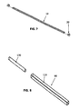
FIG. 7 is a perspective view of the cross support shown of FIGS. 1 and 4.
FIG. 8 is a perspective view of the leg shown in FIGS. 1 and 4 pre-fabrication.
FIG. 9 is a perspective view of one embodiment of a modular portable light hanger as disassembled in an exploded view.
FIG. 10 is a perspective view of a hanger-to-tray stand corner transition, in one embodiment.
FIG. 11 is a bottom view of a hanger-to-tray stand corner transition, in one embodiment.
FIG. 12 is a perspective view of a modular portable light hanger as assembled and combined with a modular tray stand, according to various embodiments.
FIG. 13 is a perspective partial view of a hanger-to-tray stand corner transition as combined with a light hanger corner pole and perimeter members and leg of a tray stand, according to various embodiments.
FIG. 14 is a perspective view of a tray stand leg as disassembled in an exploded view, according to one embodiment.
DETAILED DESCRIPTION OF THE FIGURES
In the following discussion that addresses one embodiment of the present invention, reference is made to the accompanying figures that form a part hereof, and in which is shown by way of illustration, one specific embodiment in which the invention may be practiced. It is to be understood that other embodiments may be realized and utilized with changes made without departing from the scope of the present invention. Various inventive features are described below that can each be used independently of one another or in combination with other features.
FIG. 1 shows a perspective view of one embodiment of the modular tray stand as disassembled in an exploded view. The preferred embodiment is constructed primarily of square tubing, but could be constructed from sheet metal, round tubing, cast aluminum or injection molded in plastic and depending on the application, would benefit from combinations of the above materials in the construction of the stand.
The frame perimeter 6 is defined by the top surfaces of the first base frame 30A, second base frame 30B, a first side frame 40A, and second side frame 40B. The frame perimeter 6 is the surface on or in which the supported item may rest. For the application as a plant tray stand, the plant tray would insert within the frame perimeter 6, and rest upon the top of the frame perimeter 6. For heavier support applications, cross supports 10 are added to increase rigidity to the stand 1, while also providing additional support under the item to be supported, in this embodiment the propagation tray, to prevent distortion or unlevel support. The frame perimeter 6 may be of any four sided shape having any desired length and width matching the requirements of the item to be supported. The depth 8 of the stand is also adaptable to accommodate the desired item to be supported.
In FIG. 1, the frame perimeter 6 is defined and described in clockwise order by a first base frame 30A, a first side frame 40A, a second base frame 30B and a second side frame 40B. At each corner 7A-D, a leg 90 extends down towards the ground where a wheel 100 maybe be conveniently engaged for the purposes of making the stand 1 mobile.
As shown in FIGS. 1, 3, and 4, the first base frame 30A and second base frames 30B are identical in construction, thereby making for economical manufacture. For the manufacture of the preferred embodiment, the base top tube 31 and base bottom tubes 32 are constructed of square metal tubing cut at the same length matching the corresponding frame perimeter 6 shape and size. The base top tube 31 and base bottom tube 32 are located parallel to one another, at a distance between each matching the desired depth 8 of the stand 1. A base flat plate 34 is welded onto each of the ends of the base top tube 31 and base bottom tube 32 such that a tab 35 extends past the base bottom tube 32 at both of the bottom tube's 32 ends. For the preferred embodiments shown, the base receiver 33 is constructed from square tubing, and in length matching half the length of the flat plate 34 not including the tab 35. The base receiver 33 is welded to each base flat plate 34 as shown.
As shown in FIGS. 1, 2, and 4, the first side frame 40A and second side frame 40B are identical, and constructed in the same manner as the first base frame 30A and second base frame 30B with the only difference being the side flat plate 44 being shorter as no tab extends past the side top tube 41 or side bottom tube 42.
In FIGS. 1, 2, 3, and 4, the preferred embodiment benefits from the side receiver 43 being of the same length as the base receiver 33, which allows for easier and more economical manufacture as all of the receivers are of the same construction.
As shown in FIGS. 1, 4, and 8, the four legs 90 have at least one flat side 110 and a dowel 120 on one end. For mobile applications a wheel 100 is engaged at the opposing leg 90 end from the dowel 120. The dowel 120 is of sufficient size to fittingly insert within the base receivers 33 and side receivers 43. As shown in the preferred embodiment, the dowel 120 is constructed of round tubing that is just small enough to fit within the base receivers 33 and side receivers 43. Tubing was used in the preferred embodiment to keep the overall weight down, however, the dowel 120 may be of solid rod material, or schedule 40 pipe, all depending on the application.
As shown assembled in FIG. 1, the dowel 120 does not extend out of the side receiver 43, however, in other embodiments and applications the dowel 120 is of greater length and extends out of the receiver 43 providing mounting structure to facilitate the addition of other items such as light racks, plant training web, irrigation systems, covers, and other added features to increase the versatility of the stand.
FIG. 3 shows a close up of the presented embodiment for the first and second base frames 30A and 30B with the base receiver 33, base flat plate 34 and tab 35. A base top tube 31 and base bottom tube 32 fixate to the flat plate 34 by weld as shown, but any other fixation means is sufficient.
FIG. 2 shows a close up of the presented embodiment for the first and second side frames 40A and 40B, with the side receivers 43, side flat plates 44 and no tab. A side top tube 41 and a side bottom tube 42 fixate to the flat plate 44 by weld as shown, but any other fixation means is sufficient.
FIGS. 2 and 3 show exploded views of exemplary side 40A and base 30A frames, where the side receivers 43 and base receivers 33 are shown mounted with the same orientation on either the upper portion or lower portion of the side flat plates 44 or base flat plates 34, respectively. For example, the side receivers 43 are shown in FIG. 2 as being mounted on the lower portion of the side flat plates 44 nearest the side bottom tube 42, in one embodiment, but may be mounted on the upper portion of the side flat plates 44 nearest the side top tube 41 as shown in FIGS. 1 and 5. Similarly, the base receivers 33 may be mounted on the lower portion of the base flat plate 34 as shown in FIG. 3, or, in other embodiments, mounted on the upper portion of the base flat plate 34 (not shown).
In one embodiment (not shown), side receiver 43 may be mounted on the lower portion of the side flat plate 44 on one end of the side frame 40A, with the side receiver 43 on the other end of the side frame 40A mounted on the upper portion of the side flat plate 44, and base receiver 33 may be mounted on the lower portion of the base flat plate 34 on one end of the base frame 30A, with the base receiver 34 on the other end of base frame 30A mounted on the upper portion of the base flat plate 34. In one embodiment (not shown), both side and base frames are constructing as above, with one receiver mounted nearest the top tube and the other receiver mounted nearest the bottom tube, and the combination of two side frames and two base frames may be assembled to form a tray stand having an overall appearance as that shown in FIG. 4.
In yet another alternative embodiment (not shown), both side frames and base frames may be made to be identical, such as for example substantially similar to the base frame 30A shown in FIG. 3 but having a receiver 33 at one end mounted on a lower portion of the flate plate 34 and the other receiver 33 mounted on the opposite end of the frame on an upper portion of the opposite end's flate plate 34. With four identically constructed frames 30A, according to one embodiment, a tray stand may be assembled having the overall appearance as that shown in FIG. 4, the resulting tray stand requiring even fewer unique components than the tray stand 1 shown in FIG. 1.
In various embodiments, the tab 35 shown in FIG. 3 may comprise flat plate 34 material extending downward (for rotational locking contact with leg 90) below the lower most surface of bottom tube 32 (as shown, for example, in FIG. 6), or the tab 35 may comprise a portion of flat plate 34 extending downward (for rotational locking contact with leg 90) below the lower most edge of receiver 33 but not necessarily extending below the lower most surface of bottom tube 32.
FIG. 4 shows an assembled tray stand 1 comprised of the components shown in FIG. 1, in preferred embodiments. The overall shape of the frame perimeter 6 is preferably rectangular or square. In embodiments not shown, the tray stand may comprise an extra pair of corners such as 7B and 7C interconnecting the base frame 30B with an additional pair of side frames 40A and 40B, the resulting tray stand having six legs 90, base frames 30A and 30B, and two side frames 40A and two side frames 40B. Similarly, in embodiments not shown, the tray stand may comprise an extra pair of corners such as 7C and 7D interconnecting the side frame 40B with an additional pair of base frames 30A and 30B, the resulting tray stand having six legs 90, side frames 40 and 40B, and two base frames 30A and two base frames 30B. Likewise, in similar fashion as described above for the addition of either another pair of side frames (plus two additional legs) or another pair of base frames (plus two additional legs), additional pairs of either side or base frames (and corresponding legs) may be added, the resulting tray stand comprising the basic components shown in FIGS. 1 and 4 but having two extra legs, four extra legs, and so on.
FIG. 8 shows a close up exploded view of the leg 90 having the flat side 110, and dowel 120. The leg 90 is able to accept wheel, as wheels are not desirable in all applications, so having the wheels easily detach is desired, and many wheel attachment and detachment methods are well known in the art and therefore not disclosed herein. In preferred embodiments, a lower portion of the leg 90 comprises at least one flat surface 110 for rotational locking contact and engagement with a lower portion of flat plate 34 or tab 35, depending upon the particular embodiment regarding mounting of the receiver 33 to the flat plate 34. In one embodiment, the lower portion of leg 90 comprises square or rectangular tubing. In preferred embodiments, an upper portion of the leg 90 comprises a dowel 120 which inerttingly and fixatedly fits within the lower portion of the leg 90 so that insertion of the dowel 120 portion into the receivers (such as receivers 33 and 43) allows longitudinal insertion of the dowel 120 into each receiver with the lower portion of the leg 90 unable to insertingly fit into at least one of the two receivers that comprise an interlocking corner joint of the tray stand. In one embodiment, the dowel 120 intertingly fits within the receiver 33, and the lower portion 110 is unable to inertingly fit into the receiver 33, the lower portion of the leg 90 thereby providing a stop and weight bearing surfaces preventing further longitudinally downward travel of the receivers along the leg 90.
In preferred embodiments, the dowel 120 comprises round material or round tube stock as shown in FIG. 8 that is fixatingly inserted (such as instered and welded or glued in place) into the lower portion 110. The dowel 120 is preferably sized to insertingly fit within receivers 33 and 43. In alternate embodiments, the dowel 120 may be differently shaped yet still insertingly fit (for easy hand assembly and disassembly of a tray stand corner) into receivers 33 and 43. For example, in one embodiment, as shown in FIG. 14, a tray stand leg 1490 may comprise a dowel 1420 having a diamond shape 1010. The diamond shape 1010 may be formed, for example, by using press brake folded square stock tubing. The dowel 1420 having a diamond shape cross section is fixatingly inserted into the lower leg portion 1430, with the lower leg portion 1430 having at least one flat surface for rotational locking engagement with a lower portion of a flat plate 34 or tab 35. In various embodiments, the tray stand in FIGS. 1 and 4 may utilize legs 1490 in place of legs 90.
FIG. 7 shows a close up view of the cross supports 10 and U sleeve 20. These cross supports 10 may be constructed with adjustability to enable different depths of plant trays to be used as discussed earlier. Ideally, the U sleeve 20 is of shape and size such that the base top tube 31, base bottom tube 32, side top tube 41 or side bottom tube 42 fittingly insert within the crux of the “U” shape, thereby allowing fixation, without fasteners, screws, or bolts. For applications to support great mass, or in the indoor gardener setting, requiring significant water and growing media in the tray or for deeper trays that simply hold more weight, cross supports 10 having slip over U sleeve 20 provide under tray support, while increasing strength, stability, and rigidity to the entire tray stand as shown in FIG. 1 assembled.
One possible method of assembling the stand by a solo assembly involves a first step, which is to align the dowel 120 of each leg 90 shown in FIG. 8, with the base receivers 33 shown in FIG. 3, and insert the dowel 120 first through the tab 35 end of the base receivers 33 one at a time until all dowels 120 are fully and fittingly inserted within the base receivers 33. Each dowel 120 should protrude out the other side of each base receiver 33 of each tab 35 parallels in mating contact to a flat side 110 of each leg.
The second step in a one person assembly is to locate the now inserted legs 90 and the first and second base frames 30A and 30B parallel to one another, and spaced apart at a distance approximately matching the length of the first side frame 40A and second side frame 40B.
The third and final step in a one person assembly is to position the first side frame 40A such that the exposed side flat plate 44 end of the side receivers 43 are over and aligned with the dowels 120 protruding from the first base frame 30A and the corresponding end of second base frame 30B such that when the first side frame 40A is brought down the exposed flat plate 44 comes to rest against one side of the corresponding base receiver 33, and the dowels 120 fittingly slide within the corresponding side receivers 43 such that corners 7A and 7B are defined and three sides of the perimeter frame 6 is defined as shown in FIG. 1. The second side frame 40B is slid over the remaining protruding dowels 120 in the same manner as the first side frame 40A, thereby completing the four sides and frame perimeter 6 and defining corners 7C and 7D as shown assembled in FIG. 4. Disassembly is the same except in reverse order.
Another method of assembly involves assembling the stand one corner 7A-D at a time: First by inserting one end of the first leg 90 through one end of the first base frame 30A and then inserting the same end of the first leg 90 through one end of the first side frame 40A, locating the other end of the first leg towards the ground, thereby forming a first corner 7A of the stand 1; Second, by inserting one end of the second leg 90 through one end of the second base frame 30B, and then inserting the same end of the second leg 90 through the other end of the first side frame 40A, locating the other end of the second leg 90 towards the ground thereby forming a second corner 7B; Third, by inserting one end of the third leg 90 through the other end of the first base frame 30A, and then inserting the same end of the third leg through one end of the second side frame 40B, locating the other end of the third leg towards the ground thereby forming the third corner 7C; and Fourth, inserting one end of the fourth leg 90 through the other end of the second base frame 30B, and then inserting the same end of the fourth leg 90 through the other end of the second side frame 40B, locating the other end of the fourth leg towards the ground thereby forming the fourth corner 7D. When all four legs have been inserted as per steps above, the stand 1 will ready to receive plant tray, table top, fish tank, or any other square or rectangular base object.
Once assembled as shown in the preferred embodiment in FIGS. 1-8, each base flat plate 34 and side flat plate 44 parallels in mating contact with a corresponding side of a base receiver 33 and side receiver 43, whereby the first and second base frames 30A and 30B rigidly interlock with the first and second side frames 40A and 40B having the dowel 120 maintain the interlocking alignment and rigidly engage the corresponding leg 90 at the corresponding corners 7A-D. The weight of the components of the stand 1 provides the constant force to maintain the interlock at the corners locking the frame together once assembled as shown in FIG. 4. As weight is added to the frame perimeter, or at optional cross supports 10, the components deflect and distort minimally thereby tightening the interlocking effect at the corners 7A-D, and increasing the strength and rigidity of the stand 1. In short, the more weight added, the stronger the interlock, and more stable the stand becomes. Remove the weight, and the stand 1 easily knocks down into it's modular components for quick and convenient storage or transport.
FIG. 9 is a perspective view of one embodiment of a modular portable light hanger 900 as disassembled in an exploded view. In preferred embodiments, the light hanger 900 comprises four corner (or wall) poles 902, interconnected with four (ceiling) perimeter poles 904 using press-fit type 3-way corner connectors 910, at least one equipment/light hanger pole such as the equipment/light hanger poles 906 and equipment/light hanger pole 908 having equipment/light hanger connectors 912 at each end for tooless interconnection with perimeter poles 904 (as shown), and four hanger-to-tray stand corner transition adapters 1000 for toolessly interconnecting each of the corner poles 902 with a corner joint of the tray stand. Each of the poles 902, 904, 906, 908 preferably comprise tubular metal, but may comprise other materials and shapes, such as square or rectangular material. And each of the 3-way connectors 910 and hanger connectors 912 preferably comprise plastic connectors substantially as shown and sized to snugly and securely receive and interconnect the poles 902, 904, 906, and 908, as shown in FIG. 12. In preferred embodiments, the light hanger 900 comprises eleven poles, each substantially identical in diameter and length and interchangeable with one another so that a pole used as a corner pole 902 may be repurposed as a perimeter pole 904 or hanger pole 906 or 908. Preferably the corner connectors 910 and hanger pole end connectors 912 fit over the ends of any pole. In other embodiments, not shown, poles of varying lengths may be used. For example, the four corner poles 902 may be of different length than the perimeter poles 904 and hanger poles 906 and 908. And for example, the perimeter poles 904 (and corresponding hanger poles 906 and 908) may be of different lengths from one another if the base and side frames comprising the perimeter 6 of the tray stand 1 form a rectangle instead of a square.
In preferred embodiments, each of the poles 902, 904, 906, and 908 comprising the light hanger 900 comprise pole members having the same cross-sectional dimensions. Preferably, each of the corner and perimeter poles share a common cross-sectional diameter.
FIG. 10 is a perspective view of a hanger-to-tray stand corner transition (or adapter) 1000, in one embodiment. The hanger-to-tray stand adapter 1000 preferably comprises a unitary component having a corner (wall) pole engaging receiver 1020 sized to receive an end of a corner pole 902. The corner pole engaging receiver 1020 is fixably mounted to a corner transition overhang portion 1030, upon which first 1040 and second 1050 corner transition tray stand outer engagement surfaces extend in a downward direction, parallel to and engaging with a tray stand leg 90, opposite to the direction that the corner pole engaging receiver 1020 extends, the corner pole engaging receiver 1020 extending upward and parallel with a corresponding inserted corner pole 902. Also preferably extending parallel to the first 1040 and second 1050 corner transition tray stand outer engagement surfaces, is a diamond shaped dowel 1010, sized and shaped to insertingly fixate within an open top of a tray stand receiver such as side frame receiver 43.
FIG. 11 is a bottom view of a hanger-to-tray stand corner transition 1000, in one embodiment. The diamond shaped dowel 1010 is preferably sized and oriented with respect to the first corner transition tray stand outer engagement surface 1040 and the second corner transition tray stand outer engagement surface 1050 so as to provide a space at least as large as the material thickness of the tray stand receiver, such as side receiver 43. The diamond shaped dowel 1010 is preferably sized so that each point (or corner) of its star/diamond cross sectional shape snugly fits within an inside corner of square tube stock comprising each tray stand receiver 43.
FIG. 12 is a perspective view of a modular portable light hanger 900 as assembled and combined with a modular tray stand 1, according to various embodiments. The light hanger components shown in FIG. 9 are most preferably assembled (and disassembled) by hand and without any tools or fasteners or hardware, and are likewise preferably assembled (and disassembled) by hand and without any tools or hardware to a tray stand 1 with four adapters 1000 providing the interconnection between the light hanger 900 and the tray stand 1.
FIG. 13 is a perspective partial view of a hanger-to-tray stand corner transition 1000 as combined with a light hanger corner pole 902 and perimeter members 6 and leg 90 of a tray stand 1, according to various embodiments. As shown in FIG. 13, the transition (adapter) 1000 comprises a substantially flat overhang member upon which a corner pole engaging receiver 1020 extends upward and from which corner transition tray stand outer engagement surfaces 1040 and 1050 and corner transition dowel 1010 extend downward. The adapter 1000 preferably comprises overhang material 1310 that is substantially coplanar (within a material thickness of the overhang material) to the upper most surfaces of (and plane formed by) the tray stand perimeter 6. In preferred embodiments, the adapter 1000 comprises a receiver 1020 sized to receive a round tube light hanger corner pole 902, flat overhang material 1320 whereby the receiver 1020 is oriented so as not to cover the perimeter 6 or corner of the tray stand 1, and tray stand receiver engaging material such as the engaging surfaces 1040 and 1050 and dowel 1010. The receiver engaging material 1040 and 1050 may comprise surfaces that extend further downward for contact engagement with larger surface areas of the tray stand receiver than shown. The flat overhang material 1310 may, in some embodiments, extend across the top surface of tray stand perimeter 6 more than shown. In most preferred embodiments, the flat overhang material 1310 of the transition/adapter 1000 orients the receiver 1020 so that the edges of a plant growing tray may overlap the perimeter 6 of the tray stand and allow enough space for the transition/adapter 1000 to receive and interconnect with corner poles 902 for hand/tooless assembly and disassembly of a light hanger 900 in combination with a tray stand, substantially as shown in FIG. 12.
The terms and expressions which have been employed in the foregoing specification are used therein as terms of description and not of limitation, and there is no intention in the use of such terms and expressions of excluding equivalents of the features shown and described or portions thereof, it being recognized that the scope of the invention is defined and limited only by the claims which follow.

Claims (5)

What is claimed is:
1. A modular portable light hanger for use with a modular portable tray stand, comprising:
(a) four corner poles;
(b) four perimeter poles interconnectable with the top ends of said corner poles by hand and without the need for tools or hardware;
(c) at least one equipment bearing pole extending between two of said four perimeter poles, the equipment bearing pole interconnectable with said perimeter poles by hand and without the need for tools or hardware;
(d) four corner adapters, each having a dowel directed downward and insertable into an open end of a tubular receiver of a tray stand corner joint, at least one surface extending parallel to said dowel for engagement with an exterior surface of said tubular receiver, and a corner pole receiver directed opposite said dowel and sized to receive insertion of a lower end of one of said corner poles, said corner adapters interconnectable with said corner poles by hand and without the need for tools or hardware.
2. The light hanger of claim 1 wherein said corner poles, perimeter poles, and at least one equipment bearing pole comprise round tubular metal poles of the same diameter.
3. The light hanger of claim 1 wherein said poles and adapters are repeatably interconnectable for repeatable assembly and disassembly by hand and without the need for tools or hardware.
4. The light hanger of claim 1 wherein said dowel has a diamond shaped cross section and is sized to snugly and rotatingly securely insert into square tubular material used for said tubular receiver of said tray stand corner joint.
5. The light hanger of claim 1 further comprising a tray stand having four legs and four sides, said four legs and four sides being interconnectable for repeatable assembly and disassembly by hand and without the need for tools or hardware.
US14/871,811 2011-02-08 2015-09-30 Light hanger Active US9468288B2 (en)

Priority Applications (2)

Application Number Priority Date Filing Date Title
US14/871,811 US9468288B2 (en) 2011-02-08 2015-09-30 Light hanger
US15/274,842 US20170086390A1 (en) 2011-02-08 2016-09-23 Light hanger

Applications Claiming Priority (5)

Application Number Priority Date Filing Date Title
US201161462760P 2011-02-08 2011-02-08
US13/136,657 US8714498B2 (en) 2011-02-08 2011-08-08 Tray stand
US14/269,619 US9084478B2 (en) 2011-02-08 2014-05-05 Modular portable stand
US14/750,829 US9615657B2 (en) 2011-02-08 2015-06-25 Corner joint for modular portable stand
US14/871,811 US9468288B2 (en) 2011-02-08 2015-09-30 Light hanger

Related Parent Applications (1)

Application Number Title Priority Date Filing Date
US14/750,829 Continuation-In-Part US9615657B2 (en) 2011-02-08 2015-06-25 Corner joint for modular portable stand

Related Child Applications (1)

Application Number Title Priority Date Filing Date
US15/274,842 Continuation US20170086390A1 (en) 2011-02-08 2016-09-23 Light hanger

Publications (2)

Publication Number Publication Date
US20160014979A1 US20160014979A1 (en) 2016-01-21
US9468288B2 true US9468288B2 (en) 2016-10-18

Family

ID=46600010

Family Applications (7)

Application Number Title Priority Date Filing Date
US13/136,657 Active US8714498B2 (en) 2011-02-08 2011-08-08 Tray stand
US14/269,619 Active US9084478B2 (en) 2011-02-08 2014-05-05 Modular portable stand
US29/509,634 Active USD756690S1 (en) 2011-02-08 2014-11-19 Modular portable stand
US14/750,829 Active US9615657B2 (en) 2011-02-08 2015-06-25 Corner joint for modular portable stand
US14/871,811 Active US9468288B2 (en) 2011-02-08 2015-09-30 Light hanger
US29/562,014 Active USD836955S1 (en) 2011-02-08 2016-04-21 Modular portable stand
US15/274,842 Abandoned US20170086390A1 (en) 2011-02-08 2016-09-23 Light hanger

Family Applications Before (4)

Application Number Title Priority Date Filing Date
US13/136,657 Active US8714498B2 (en) 2011-02-08 2011-08-08 Tray stand
US14/269,619 Active US9084478B2 (en) 2011-02-08 2014-05-05 Modular portable stand
US29/509,634 Active USD756690S1 (en) 2011-02-08 2014-11-19 Modular portable stand
US14/750,829 Active US9615657B2 (en) 2011-02-08 2015-06-25 Corner joint for modular portable stand

Family Applications After (2)

Application Number Title Priority Date Filing Date
US29/562,014 Active USD836955S1 (en) 2011-02-08 2016-04-21 Modular portable stand
US15/274,842 Abandoned US20170086390A1 (en) 2011-02-08 2016-09-23 Light hanger

Country Status (5)

Country Link
US (7) US8714498B2 (en)
EP (1) EP2725947B1 (en)
CN (1) CN103501660B (en)
AU (1) AU2012290715B2 (en)
WO (1) WO2013019268A1 (en)

Cited By (3)

* Cited by examiner, † Cited by third party
Publication number Priority date Publication date Assignee Title
USD836955S1 (en) 2011-02-08 2019-01-01 Hgci, Inc. Modular portable stand
USD853624S1 (en) 2014-11-19 2019-07-09 Hgci, Inc. Corner adapter
WO2019178915A1 (en) * 2018-03-19 2019-09-26 常州新亚奥特多金属制品有限公司 Tray platform

Families Citing this family (72)

* Cited by examiner, † Cited by third party
Publication number Priority date Publication date Assignee Title
US9891089B2 (en) * 2013-04-15 2018-02-13 OW Investors, LLC. Modular fluid meter test bench
US20150335261A1 (en) * 2014-05-21 2015-11-26 Aspect Imaging Ltd. Expandable cage surrounding a magnetic resonance device and methods thereof
KR101436965B1 (en) * 2014-07-16 2014-09-12 삼인싸이언스(주) Assembly Systems of a laboratory table
USD797479S1 (en) * 2015-06-30 2017-09-19 Mircea Manea Glass top table
US9456689B1 (en) * 2015-07-17 2016-10-04 Michael Robert Tinsley Plant growing heavy weight bearing support assembly, apparatus and system
USD807671S1 (en) * 2016-02-25 2018-01-16 Williams-Sonoma, Inc. Furniture base
USD786510S1 (en) * 2016-04-12 2017-05-09 Nevio D. Murljacic Pet highchair
CN105962695A (en) * 2016-06-17 2016-09-28 苏州华驰机械有限公司 Sliding tray supporting assembly
US10214151B1 (en) * 2017-10-10 2019-02-26 Allen Wesley Lindsay Multipurpose utility rack
CN110150845A (en) * 2017-12-22 2019-08-23 浙江传媒学院 A kind of hanging lifting type dining table
USD898485S1 (en) * 2018-03-21 2020-10-13 Target Brands, Inc. Display unit
USD909102S1 (en) * 2018-06-28 2021-02-02 Walker Edison Furniture Company Llc Stand
USD878822S1 (en) 2018-06-28 2020-03-24 Walker Edison Furniture Company Llc Stand
CA3053026A1 (en) 2018-09-07 2020-03-07 Signalisation D'urgence Rh Inc. Collapsible warning device and method for emitting a light signal
US11000134B2 (en) * 2018-11-20 2021-05-11 Target Brands, Inc. Tiered display unit
USD904084S1 (en) 2019-01-23 2020-12-08 Walker Edison Furniture Company Llc Table
USD916537S1 (en) 2019-01-23 2021-04-20 Walker Edison Furniture Company Llc Table
USD904801S1 (en) 2019-01-23 2020-12-15 Walker Edison Furniture Company Llc Console
USD904802S1 (en) 2019-01-23 2020-12-15 Walker Edison Furniture Company Llc Console
USD904079S1 (en) 2019-01-23 2020-12-08 Walker Edison Furniture Company Llc Console
US10791831B1 (en) * 2019-06-05 2020-10-06 James Tanner Table footrest apparatus
USD908405S1 (en) 2019-07-22 2021-01-26 Walker Edison Furniture Company Llc Console
USD914400S1 (en) 2019-07-22 2021-03-30 Walker Edison Furniture Company Llc Console
USD900510S1 (en) 2019-07-22 2020-11-03 Walker Edison Furniture Company Llc Console
USD908404S1 (en) 2019-07-22 2021-01-26 Walker Edison Furniture Company Llc Cabinet
USD909797S1 (en) 2019-07-22 2021-02-09 Walker Edison Furniture Company Llc Console
USD926500S1 (en) 2019-07-22 2021-08-03 Walker Edison Furniture Company Llc Cabinet
USD915799S1 (en) 2019-07-23 2021-04-13 Walker Edison Furniture Company Llc Table
USD904804S1 (en) 2019-07-23 2020-12-15 Walker Edison Furniture Company Llc Console
USD904803S1 (en) 2019-07-23 2020-12-15 Walker Edison Furniture Company Llc Console
USD927898S1 (en) 2019-07-23 2021-08-17 Walker Edison Furniture Company Llc Console
USD906020S1 (en) 2019-07-23 2020-12-29 Walker Edison Furniture Company Llc Console
US11350770B2 (en) 2019-11-07 2022-06-07 Signode Industrial Group Llc Storage, shipping, and display unit
USD931016S1 (en) 2020-01-15 2021-09-21 Walker Edison Furniture Company Llc Console
USD973399S1 (en) 2020-01-15 2022-12-27 Walker Edison Furniture Company Llc Console
USD958566S1 (en) 2020-01-15 2022-07-26 Walker Edison Furniture Company Llc Console
USD957850S1 (en) 2020-01-16 2022-07-19 Walker Edison Furniture Company Llc Buffet
USD963381S1 (en) 2020-01-16 2022-09-13 Walker Edison Furniture Company Llc Console
USD970266S1 (en) 2020-01-16 2022-11-22 Walker Edison Furniture Company Llc Console
USD904082S1 (en) 2020-01-16 2020-12-08 Walker Edison Furniture Company Llc Console
USD982331S1 (en) 2020-01-17 2023-04-04 Walker Edison Furniture Company Llc Bench
USD906021S1 (en) 2020-01-21 2020-12-29 Walker Edison Furniture Company Llc Console
US11083283B1 (en) * 2020-02-11 2021-08-10 EP Family Corp. Table assembly and method
USD941614S1 (en) 2020-07-20 2022-01-25 Walker Edison Furniture Company Llc Console
USD951684S1 (en) 2020-07-20 2022-05-17 Walker Edison Furniture Company Llc Console
USD975473S1 (en) 2020-07-20 2023-01-17 Walker Edison Furniture Company Llc Table
USD966757S1 (en) 2020-07-20 2022-10-18 Walker Edison Furniture Company Llc Console
USD946317S1 (en) 2020-07-20 2022-03-22 Walker Edison Furniture Company Llc Console
USD946319S1 (en) 2020-07-20 2022-03-22 Walker Edison Furniture Company Llc Console
USD941064S1 (en) 2020-07-20 2022-01-18 Walker Edison Furniture Company Llc Console
USD947581S1 (en) 2020-07-21 2022-04-05 Walker Edison Furniture Company Llc Console
USD954475S1 (en) 2020-07-21 2022-06-14 Walker Edison Furniture Company Llc Console
USD922798S1 (en) 2020-07-21 2021-06-22 Walker Edison Furniture Company Llc Console
USD988767S1 (en) 2020-07-22 2023-06-13 Walker Edison Furniture Company Llc Table
USD945187S1 (en) 2020-07-22 2022-03-08 Walker Edison Furniture Company Llc Console
USD938204S1 (en) * 2020-08-17 2021-12-14 Qichao Li Variable shelf
USD961964S1 (en) * 2021-01-26 2022-08-30 Walker Edison Furniture Company Llc Desk
USD979295S1 (en) 2021-01-26 2023-02-28 Walker Edison Furniture Company Llc Sideboard
USD979294S1 (en) 2021-01-26 2023-02-28 Walker Edison Furniture Company Llc Cabinet
USD978581S1 (en) 2021-01-27 2023-02-21 Walker Edison Furniture Company Llc Console
USD985972S1 (en) 2021-06-14 2023-05-16 Walker Edison Furniture Company Llc Sideboard
USD988036S1 (en) 2021-06-28 2023-06-06 Walker Edison Furniture Company Llc Cabinet
USD1005747S1 (en) 2021-06-29 2023-11-28 Walker Edison Furniture Company Llc Sideboard
USD997612S1 (en) 2021-06-29 2023-09-05 Walker Edison Furniture Company Llc Table
USD992942S1 (en) 2021-06-29 2023-07-25 Walker Edison Furniture Company Llc Table
USD1010362S1 (en) 2021-11-03 2024-01-09 Walker Edison Furniture Company Llc Cabinet
USD1013424S1 (en) 2021-12-07 2024-02-06 Walker Edison Furniture Company Llc Console
USD979993S1 (en) 2021-12-07 2023-03-07 Walker Edison Furniture Company Llc Table
USD1010367S1 (en) 2021-12-09 2024-01-09 Walker Edison Furniture Company Llc Console
KR102542709B1 (en) * 2021-12-10 2023-06-14 최용수 Support unit for stage apparatus toy set
USD1011104S1 (en) * 2023-06-08 2024-01-16 Pai Liu 5 gallon water bottle holder
KR102635581B1 (en) * 2023-10-18 2024-02-08 (주)소호모형 Model Building Exhibition Stand

Citations (66)

* Cited by examiner, † Cited by third party
Publication number Priority date Publication date Assignee Title
US1912847A (en) 1931-02-05 1933-06-06 Walker Mfg Co Rest for tiering trucks
US2695712A (en) 1951-12-10 1954-11-30 William G Kolander Serving tray
US2794496A (en) 1954-11-15 1957-06-04 Jr Bert F Strand Knock-down support means
US3013670A (en) 1959-08-26 1961-12-19 Mayer Nathan Knockdown furniture assembly
US3121496A (en) 1962-05-07 1964-02-18 Brilliant Products Inc Display racks
US3172376A (en) 1962-11-30 1965-03-09 Adolph J Havlis Display rack
US3189363A (en) 1963-11-08 1965-06-15 Precitec Co Inc Mobility adapters
US3502227A (en) 1967-10-18 1970-03-24 Speedrack Inc Storage rack
US3517828A (en) * 1968-08-13 1970-06-30 Ralph E Hunter Rack stacking guide
US3599580A (en) 1970-06-01 1971-08-17 Gusdorf & Sons Table assembly
US3765541A (en) 1971-04-07 1973-10-16 Poster Products Structural units and method of assembling them
US3787072A (en) 1971-11-04 1974-01-22 Servicemaster Hospital Corp Laundry hamper stand
US3919603A (en) * 1973-02-21 1975-11-11 Westinghouse Electric Corp Switchboard framework corner tie
US3997139A (en) 1973-11-23 1976-12-14 Pentaco Enterprises Corporation Knockdown aquarium stand
US4099735A (en) 1976-09-13 1978-07-11 Metropolitan Wire Corporation Convertible cart
US4179169A (en) 1977-12-01 1979-12-18 Honeywell Information Systems Inc. Facade for a data processing system
USD254994S (en) 1977-10-06 1980-05-13 Michael Miereanu Aquarium stand
US4419938A (en) * 1980-12-06 1983-12-13 Albin Kaut Plug-assembled sectional display rack
US4516376A (en) * 1982-02-24 1985-05-14 King Lionel W Assembly system
US4630550A (en) 1985-04-02 1986-12-23 Jack J. Weitzman Prefabricated knock-down metal-frame work table
US4684087A (en) 1986-03-20 1987-08-04 Spickard Gerald V Grocery bag holder and kit for the assembly thereof
US4773547A (en) 1987-02-02 1988-09-27 Bell Ferris A Stackable and nestable storage rack
US4832421A (en) 1988-04-27 1989-05-23 Shoffner Donald I Ready-to-assemble cabinet
USD304982S (en) 1988-10-31 1989-12-12 Bush Industries, Inc. Stand or similar article
US4974526A (en) 1988-12-27 1990-12-04 Wiygul Jr Frank H Portable self-storing folding table
US5016765A (en) 1989-08-23 1991-05-21 Leonardo Stephen V Modular frame assembly and method for making same
USD321571S (en) 1989-08-23 1991-11-12 Lucariello John D Aquarium-support cabinet
US5257794A (en) 1992-04-10 1993-11-02 Yazaki Industrial Chemical Co., Ltd. Corner joint, chassis and cart
US5313725A (en) 1992-05-22 1994-05-24 Devassie Terry L Changeable display newspaper vending machine
US5335605A (en) 1991-08-30 1994-08-09 Engineered Data Products, Inc. Decorative panel construction for office furniture
US5370245A (en) * 1992-04-03 1994-12-06 The Bottle Buddy, Inc. Water cooler bottle storage stand and system
US5437165A (en) 1993-09-13 1995-08-01 White; Richard W. Food organizer insert for portable ice chest
US5517928A (en) 1994-02-16 1996-05-21 Erdman; Anthony E. Joints for tubular-framed modular furniture
US5527103A (en) 1993-10-01 1996-06-18 Pittman; Charles Cabinet of improved design and construction
US5531464A (en) 1994-12-09 1996-07-02 Maurer; Raymond N. Cart with snap-locking members
US5579703A (en) 1994-09-12 1996-12-03 King; Richard Support stand for bird cages, fish tanks and the like
CN1149434A (en) 1995-10-30 1997-05-14 吉田司 Connecting parts for assembled combined cabinet and combined cabinet with said parts
US5645331A (en) 1994-09-30 1997-07-08 Kel-Jac Engineering And Plastic Sales, Inc. Lower front for water coolers, and apparatus and method for renovating water coolers
US5678706A (en) 1994-01-19 1997-10-21 Rollpa International, S.R.O. Modular furniture
US5813737A (en) 1997-02-13 1998-09-29 Stone; Adrian Thomas Construction system
US5931019A (en) 1997-11-15 1999-08-03 White; Richard W. Bait tray insert assembly for portable cooler
US5941183A (en) 1998-06-05 1999-08-24 Formosa Saint Jose, Corp. Light weight portable combination table structure for exhibition use
US5943968A (en) 1994-11-12 1999-08-31 Senator International Limited Collapsible support structure
US5954412A (en) 1998-03-12 1999-09-21 Rutherford; Richard High load aquarium support cabinet
US6027000A (en) 1996-02-29 2000-02-22 Sterzel; Helmut Walter Device for preventing items of luggage from slipping or tipping in vehicle boots
US6073320A (en) 1997-08-01 2000-06-13 Batesville, Services, Inc. Casket display structure
US6135299A (en) * 1999-06-11 2000-10-24 B 4 Enterprises, Inc. Product display and transport rack
US6205738B1 (en) * 1999-03-29 2001-03-27 Yang Fan Development Co., Ltd. Frame for forming a housing of a group of air-handling units
US6213333B1 (en) 1999-02-04 2001-04-10 Johnny J. Icard Utensil tray and method
US6454261B2 (en) 2000-05-25 2002-09-24 Ohiragiken Industry Co. Game machine
US6550791B2 (en) 1999-12-10 2003-04-22 William Aaron Ramsey Multi-purpose cart
US6581221B2 (en) 2001-09-04 2003-06-24 Terry L. Rosenquist Support structure for a bed or the like
US6651456B1 (en) 2003-04-28 2003-11-25 Robert White Shelf surrounding ice chest with cart
US6811163B1 (en) 2002-08-01 2004-11-02 Gurule Jim Cabinet transport and storage cart
US6902074B2 (en) 2002-06-11 2005-06-07 Caitec Corporation Support stand
US6948435B1 (en) * 2003-03-20 2005-09-27 Honeyware, Inc. Corner joint and shelf module for use in light-duty all-plastic shelf units
US6969077B2 (en) 2003-07-29 2005-11-29 Shinn Fu Corporation Two-way caster bench
US7055834B1 (en) 2004-04-22 2006-06-06 White Richar W Knock-down ice chest stand/cart
US7152749B2 (en) 2001-09-24 2006-12-26 Tech-Source, Inc. All-terrain vehicle shipping package
US7165749B2 (en) 2004-09-20 2007-01-23 Alberto John Venezia Interlocking aquarium support system with interchangeable multifunctional decorative facade
US20070095770A1 (en) 2005-10-27 2007-05-03 Backofen Paul J Fish tank stand
US20080191538A1 (en) 2007-02-09 2008-08-14 Robin Berg System and method for modular furniture assembly
CN101505585A (en) 2006-04-10 2009-08-12 金正会 Prefabrication type flowerpot block
US20090284111A1 (en) 2008-03-24 2009-11-19 Hazzard Thomas B No-tools breakdown furniture
US20100313474A1 (en) 2009-06-12 2010-12-16 Eleanor's Garden, Llc Modular Gardening System
US20120199707A1 (en) 2011-02-08 2012-08-09 Ip Holdings Llc Tray stand

Family Cites Families (29)

* Cited by examiner, † Cited by third party
Publication number Priority date Publication date Assignee Title
US2789531A (en) * 1955-04-11 1957-04-23 Aurel E Diefendorf Collapsible cage for birds
US4112853A (en) * 1977-07-05 1978-09-12 Custom Plastics, Inc. Shelving apparatus
AU628170B2 (en) * 1989-05-09 1992-09-10 Ilmar Pold Improvements relating to connectors
US6286405B1 (en) * 1998-11-04 2001-09-11 Richard Ernest Dunbar Hamm Workbench
USD553398S1 (en) * 2006-04-20 2007-10-23 Kohler Co. Support
USD641559S1 (en) * 2009-08-11 2011-07-19 Maximideas Inc. Book stand
USD639448S1 (en) * 2009-11-30 2011-06-07 Allan Grainger Support frame
USD636039S1 (en) * 2010-08-27 2011-04-12 Coulter Ventures, LLC Exercise rack
USD636038S1 (en) * 2010-08-27 2011-04-12 Coulter Ventures, LLC Exercise rack
USD636040S1 (en) * 2010-08-27 2011-04-12 Coulter Ventures, LLC Exercise rack
USD660614S1 (en) * 2010-09-21 2012-05-29 Palmeiri Charles J Outboard motor stand
CN201830709U (en) * 2010-10-13 2011-05-18 杭州兆世进出口有限公司 Parterre assembly with changeable height
USD668894S1 (en) * 2011-06-08 2012-10-16 Target Brands, Inc. Pair of support legs
USD716079S1 (en) * 2011-07-07 2014-10-28 Toy Wonders, Inc. Display fixture
USD670353S1 (en) * 2011-07-21 2012-11-06 Mallard Motels, LLC Decoy stand
USD677932S1 (en) * 2012-07-24 2013-03-19 Wen-Tsan Wang Clothes stand
USD730089S1 (en) * 2012-10-29 2015-05-26 S & S Inc. Product shipping and display shelving unit
USD682639S1 (en) * 2012-12-21 2013-05-21 Dasco Pro, Inc. Plant support
USD702954S1 (en) * 2013-01-22 2014-04-22 Lyle Bentley Double extension for a tree stand
USD727071S1 (en) * 2013-07-06 2015-04-21 Howard Cohen Decorative shelf stand
USD731212S1 (en) * 2013-09-13 2015-06-09 Seville Classics, Inc. Modular utility rack
USD730086S1 (en) * 2013-09-13 2015-05-26 Okamura Corporation Table with monitor stand
USD736601S1 (en) * 2013-11-19 2015-08-18 James R. Cox Hose support device
US9492009B2 (en) * 2014-03-14 2016-11-15 Honda Logistics North America, Inc. Collapsible and stackable parts rack
USD786492S1 (en) * 2014-11-19 2017-05-09 Ip Holdings, Llc Modular portable light hanger
USD787243S1 (en) * 2015-06-29 2017-05-23 Safavieh Inc. Display fixture and pallet
USD775703S1 (en) * 2015-08-14 2017-01-03 Michael R. Throgmorton Universal archery bow stand
USD802340S1 (en) * 2016-06-07 2017-11-14 D B Imports, LTD. Double-wide modular display fixture
USD790137S1 (en) * 2016-06-29 2017-06-20 Eric Scotti Beehive stand

Patent Citations (73)

* Cited by examiner, † Cited by third party
Publication number Priority date Publication date Assignee Title
US1912847A (en) 1931-02-05 1933-06-06 Walker Mfg Co Rest for tiering trucks
US2695712A (en) 1951-12-10 1954-11-30 William G Kolander Serving tray
US2794496A (en) 1954-11-15 1957-06-04 Jr Bert F Strand Knock-down support means
US3013670A (en) 1959-08-26 1961-12-19 Mayer Nathan Knockdown furniture assembly
US3121496A (en) 1962-05-07 1964-02-18 Brilliant Products Inc Display racks
US3172376A (en) 1962-11-30 1965-03-09 Adolph J Havlis Display rack
US3189363A (en) 1963-11-08 1965-06-15 Precitec Co Inc Mobility adapters
US3502227A (en) 1967-10-18 1970-03-24 Speedrack Inc Storage rack
US3517828A (en) * 1968-08-13 1970-06-30 Ralph E Hunter Rack stacking guide
US3599580A (en) 1970-06-01 1971-08-17 Gusdorf & Sons Table assembly
US3765541A (en) 1971-04-07 1973-10-16 Poster Products Structural units and method of assembling them
US3787072A (en) 1971-11-04 1974-01-22 Servicemaster Hospital Corp Laundry hamper stand
US3919603A (en) * 1973-02-21 1975-11-11 Westinghouse Electric Corp Switchboard framework corner tie
US3997139A (en) 1973-11-23 1976-12-14 Pentaco Enterprises Corporation Knockdown aquarium stand
US4099735A (en) 1976-09-13 1978-07-11 Metropolitan Wire Corporation Convertible cart
USD254994S (en) 1977-10-06 1980-05-13 Michael Miereanu Aquarium stand
US4179169A (en) 1977-12-01 1979-12-18 Honeywell Information Systems Inc. Facade for a data processing system
US4419938A (en) * 1980-12-06 1983-12-13 Albin Kaut Plug-assembled sectional display rack
US4516376A (en) * 1982-02-24 1985-05-14 King Lionel W Assembly system
US4630550A (en) 1985-04-02 1986-12-23 Jack J. Weitzman Prefabricated knock-down metal-frame work table
US4684087A (en) 1986-03-20 1987-08-04 Spickard Gerald V Grocery bag holder and kit for the assembly thereof
US4773547A (en) 1987-02-02 1988-09-27 Bell Ferris A Stackable and nestable storage rack
US4832421A (en) 1988-04-27 1989-05-23 Shoffner Donald I Ready-to-assemble cabinet
USD304982S (en) 1988-10-31 1989-12-12 Bush Industries, Inc. Stand or similar article
US4974526A (en) 1988-12-27 1990-12-04 Wiygul Jr Frank H Portable self-storing folding table
US5016765A (en) 1989-08-23 1991-05-21 Leonardo Stephen V Modular frame assembly and method for making same
USD321571S (en) 1989-08-23 1991-11-12 Lucariello John D Aquarium-support cabinet
US5335605A (en) 1991-08-30 1994-08-09 Engineered Data Products, Inc. Decorative panel construction for office furniture
US5370245A (en) * 1992-04-03 1994-12-06 The Bottle Buddy, Inc. Water cooler bottle storage stand and system
US5257794A (en) 1992-04-10 1993-11-02 Yazaki Industrial Chemical Co., Ltd. Corner joint, chassis and cart
US5313725A (en) 1992-05-22 1994-05-24 Devassie Terry L Changeable display newspaper vending machine
US5437165A (en) 1993-09-13 1995-08-01 White; Richard W. Food organizer insert for portable ice chest
US5527103A (en) 1993-10-01 1996-06-18 Pittman; Charles Cabinet of improved design and construction
US5678706A (en) 1994-01-19 1997-10-21 Rollpa International, S.R.O. Modular furniture
US5517928A (en) 1994-02-16 1996-05-21 Erdman; Anthony E. Joints for tubular-framed modular furniture
US5579703A (en) 1994-09-12 1996-12-03 King; Richard Support stand for bird cages, fish tanks and the like
US5645331A (en) 1994-09-30 1997-07-08 Kel-Jac Engineering And Plastic Sales, Inc. Lower front for water coolers, and apparatus and method for renovating water coolers
US5943968A (en) 1994-11-12 1999-08-31 Senator International Limited Collapsible support structure
US5531464A (en) 1994-12-09 1996-07-02 Maurer; Raymond N. Cart with snap-locking members
US5715956A (en) 1995-10-30 1998-02-10 Ns Planning Inc. Joint for modular shelves and modular shelf system using the same
CN1149434A (en) 1995-10-30 1997-05-14 吉田司 Connecting parts for assembled combined cabinet and combined cabinet with said parts
US6027000A (en) 1996-02-29 2000-02-22 Sterzel; Helmut Walter Device for preventing items of luggage from slipping or tipping in vehicle boots
US5813737A (en) 1997-02-13 1998-09-29 Stone; Adrian Thomas Construction system
US6073320A (en) 1997-08-01 2000-06-13 Batesville, Services, Inc. Casket display structure
US5931019A (en) 1997-11-15 1999-08-03 White; Richard W. Bait tray insert assembly for portable cooler
US5954412A (en) 1998-03-12 1999-09-21 Rutherford; Richard High load aquarium support cabinet
US5941183A (en) 1998-06-05 1999-08-24 Formosa Saint Jose, Corp. Light weight portable combination table structure for exhibition use
US6213333B1 (en) 1999-02-04 2001-04-10 Johnny J. Icard Utensil tray and method
US6205738B1 (en) * 1999-03-29 2001-03-27 Yang Fan Development Co., Ltd. Frame for forming a housing of a group of air-handling units
US6135299A (en) * 1999-06-11 2000-10-24 B 4 Enterprises, Inc. Product display and transport rack
US6550791B2 (en) 1999-12-10 2003-04-22 William Aaron Ramsey Multi-purpose cart
US6454261B2 (en) 2000-05-25 2002-09-24 Ohiragiken Industry Co. Game machine
US6581221B2 (en) 2001-09-04 2003-06-24 Terry L. Rosenquist Support structure for a bed or the like
US7438195B2 (en) * 2001-09-24 2008-10-21 Tech-Source, Inc. All-terrain vehicle shipping package
US7152749B2 (en) 2001-09-24 2006-12-26 Tech-Source, Inc. All-terrain vehicle shipping package
US6902074B2 (en) 2002-06-11 2005-06-07 Caitec Corporation Support stand
US6811163B1 (en) 2002-08-01 2004-11-02 Gurule Jim Cabinet transport and storage cart
US6948435B1 (en) * 2003-03-20 2005-09-27 Honeyware, Inc. Corner joint and shelf module for use in light-duty all-plastic shelf units
US6651456B1 (en) 2003-04-28 2003-11-25 Robert White Shelf surrounding ice chest with cart
US6969077B2 (en) 2003-07-29 2005-11-29 Shinn Fu Corporation Two-way caster bench
US7055834B1 (en) 2004-04-22 2006-06-06 White Richar W Knock-down ice chest stand/cart
US7165749B2 (en) 2004-09-20 2007-01-23 Alberto John Venezia Interlocking aquarium support system with interchangeable multifunctional decorative facade
US20070095770A1 (en) 2005-10-27 2007-05-03 Backofen Paul J Fish tank stand
CN101505585A (en) 2006-04-10 2009-08-12 金正会 Prefabrication type flowerpot block
US7770323B2 (en) 2006-04-10 2010-08-10 Jung-Hoi Kim Prefabrication type flowerpot block
US20080191538A1 (en) 2007-02-09 2008-08-14 Robin Berg System and method for modular furniture assembly
US20090284111A1 (en) 2008-03-24 2009-11-19 Hazzard Thomas B No-tools breakdown furniture
US20100313474A1 (en) 2009-06-12 2010-12-16 Eleanor's Garden, Llc Modular Gardening System
US20120199707A1 (en) 2011-02-08 2012-08-09 Ip Holdings Llc Tray stand
WO2013019268A1 (en) 2011-02-08 2013-02-07 Ip Holdings, Llc Tray stand
US8714498B2 (en) 2011-02-08 2014-05-06 Ip Holdings, Llc Tray stand
US9084478B2 (en) 2011-02-08 2015-07-21 Ip Holdings, Llc Modular portable stand
US20150320200A1 (en) 2011-02-08 2015-11-12 Ip Holdings, Llc Corner joint for modular portable stand

Non-Patent Citations (2)

* Cited by examiner, † Cited by third party
Title
Chinese Patent Office, Translation of Chinese Office Action for CN 201280018267.2.
Young, Lee W., International Search Report for PCT/US12/00001, issued May 1, 2012.

Cited By (4)

* Cited by examiner, † Cited by third party
Publication number Priority date Publication date Assignee Title
USD836955S1 (en) 2011-02-08 2019-01-01 Hgci, Inc. Modular portable stand
USD853624S1 (en) 2014-11-19 2019-07-09 Hgci, Inc. Corner adapter
USD854232S1 (en) 2014-11-19 2019-07-16 Hgci, Inc. Modular portable hanger
WO2019178915A1 (en) * 2018-03-19 2019-09-26 常州新亚奥特多金属制品有限公司 Tray platform

Also Published As

Publication number Publication date
US9615657B2 (en) 2017-04-11
EP2725947A1 (en) 2014-05-07
US20140239136A1 (en) 2014-08-28
US8714498B2 (en) 2014-05-06
US9084478B2 (en) 2015-07-21
AU2012290715A1 (en) 2013-09-26
AU2012290715B2 (en) 2017-05-18
US20150320200A1 (en) 2015-11-12
EP2725947A4 (en) 2015-08-05
USD756690S1 (en) 2016-05-24
US20170086390A1 (en) 2017-03-30
USD836955S1 (en) 2019-01-01
WO2013019268A1 (en) 2013-02-07
CN103501660A (en) 2014-01-08
EP2725947B1 (en) 2017-04-05
CN103501660B (en) 2016-08-17
US20120199707A1 (en) 2012-08-09
US20160014979A1 (en) 2016-01-21

Similar Documents

Publication Publication Date Title
US9468288B2 (en) Light hanger
US6902074B2 (en) Support stand
US7770743B1 (en) Support structure for hanging plants
US9603469B2 (en) Apparatuses and kits for displaying items
CA2779783C (en) Ready-to-assemble plant stand
US20030006586A1 (en) Heavy duty, knockdown industrial cart
US3815966A (en) Portable cabinet
US4917378A (en) Portable indoor/outdoor lounge swing
US7055834B1 (en) Knock-down ice chest stand/cart
US3164108A (en) Display racks
KR20230060122A (en) Variable Prefab Multi-Purpose Pedestal
US20210059125A1 (en) Metal Planter Assembly
WO2019178915A1 (en) Tray platform
US20120144737A1 (en) Above ground collapsible garden bed
CN217390223U (en) Freely combined article shelf
JPH0130039Y2 (en)
KR20140121202A (en) A flowerpot support
CN211044855U (en) Portable display board
KR20090068071A (en) The method of manufacturing wooden furniture using a traditional korean-style house technique
KR200322285Y1 (en) Sectional flat bench
RU33293U1 (en) TABLE
KR20190143751A (en) Multipurpose prefabricated shelf
KR20200069395A (en) prefabricated flowerpot wreath
KR200445252Y1 (en) Prefab Wreath Base.
CA2445810A1 (en) Plant support structure

Legal Events

Date Code Title Description
AS Assignment

Owner name: IP HOLDINGS, LLC, WASHINGTON

Free format text: ASSIGNMENT OF ASSIGNORS INTEREST;ASSIGNOR:HARGREAVES, DOUG;REEL/FRAME:038818/0953

Effective date: 20160509

STCF Information on status: patent grant

Free format text: PATENTED CASE

FEPP Fee payment procedure

Free format text: ENTITY STATUS SET TO SMALL (ORIGINAL EVENT CODE: SMAL)

AS Assignment

Owner name: HGCI, INC., NEVADA

Free format text: ASSIGNMENT OF ASSIGNORS INTEREST;ASSIGNOR:IP HOLDINGS, LLC;REEL/FRAME:046392/0064

Effective date: 20180604

FEPP Fee payment procedure

Free format text: ENTITY STATUS SET TO UNDISCOUNTED (ORIGINAL EVENT CODE: BIG.); ENTITY STATUS OF PATENT OWNER: LARGE ENTITY

MAFP Maintenance fee payment

Free format text: PAYMENT OF MAINTENANCE FEE, 4TH YEAR, LARGE ENTITY (ORIGINAL EVENT CODE: M1551); ENTITY STATUS OF PATENT OWNER: LARGE ENTITY

Year of fee payment: 4

AS Assignment

Owner name: JPMORGAN CHASE BANK, N.A., AS ADMINISTRATIVE AGENT, ILLINOIS

Free format text: SECURITY INTEREST;ASSIGNOR:HGCI, INC.;REEL/FRAME:065381/0668

Effective date: 20231027