US9463096B2 - Apparatus for anterior intervertebral spinal fixation and fusion - Google Patents
Apparatus for anterior intervertebral spinal fixation and fusion Download PDFInfo
- Publication number
- US9463096B2 US9463096B2 US14/719,895 US201514719895A US9463096B2 US 9463096 B2 US9463096 B2 US 9463096B2 US 201514719895 A US201514719895 A US 201514719895A US 9463096 B2 US9463096 B2 US 9463096B2
- Authority
- US
- United States
- Prior art keywords
- blade
- housing
- orientation
- adjacent vertebrae
- shaft
- Prior art date
- Legal status (The legal status is an assumption and is not a legal conclusion. Google has not performed a legal analysis and makes no representation as to the accuracy of the status listed.)
- Active
Links
- 0 C*1C2[C@]3[C@@]2C3C1 Chemical compound C*1C2[C@]3[C@@]2C3C1 0.000 description 1
Images


Classifications
-
- A—HUMAN NECESSITIES
- A61—MEDICAL OR VETERINARY SCIENCE; HYGIENE
- A61F—FILTERS IMPLANTABLE INTO BLOOD VESSELS; PROSTHESES; DEVICES PROVIDING PATENCY TO, OR PREVENTING COLLAPSING OF, TUBULAR STRUCTURES OF THE BODY, e.g. STENTS; ORTHOPAEDIC, NURSING OR CONTRACEPTIVE DEVICES; FOMENTATION; TREATMENT OR PROTECTION OF EYES OR EARS; BANDAGES, DRESSINGS OR ABSORBENT PADS; FIRST-AID KITS
- A61F2/00—Filters implantable into blood vessels; Prostheses, i.e. artificial substitutes or replacements for parts of the body; Appliances for connecting them with the body; Devices providing patency to, or preventing collapsing of, tubular structures of the body, e.g. stents
- A61F2/02—Prostheses implantable into the body
- A61F2/30—Joints
- A61F2/44—Joints for the spine, e.g. vertebrae, spinal discs
- A61F2/442—Intervertebral or spinal discs, e.g. resilient
- A61F2/4425—Intervertebral or spinal discs, e.g. resilient made of articulated components
-
- A—HUMAN NECESSITIES
- A61—MEDICAL OR VETERINARY SCIENCE; HYGIENE
- A61F—FILTERS IMPLANTABLE INTO BLOOD VESSELS; PROSTHESES; DEVICES PROVIDING PATENCY TO, OR PREVENTING COLLAPSING OF, TUBULAR STRUCTURES OF THE BODY, e.g. STENTS; ORTHOPAEDIC, NURSING OR CONTRACEPTIVE DEVICES; FOMENTATION; TREATMENT OR PROTECTION OF EYES OR EARS; BANDAGES, DRESSINGS OR ABSORBENT PADS; FIRST-AID KITS
- A61F2/00—Filters implantable into blood vessels; Prostheses, i.e. artificial substitutes or replacements for parts of the body; Appliances for connecting them with the body; Devices providing patency to, or preventing collapsing of, tubular structures of the body, e.g. stents
- A61F2/02—Prostheses implantable into the body
- A61F2/30—Joints
- A61F2/44—Joints for the spine, e.g. vertebrae, spinal discs
- A61F2/4455—Joints for the spine, e.g. vertebrae, spinal discs for the fusion of spinal bodies, e.g. intervertebral fusion of adjacent spinal bodies, e.g. fusion cages
- A61F2/446—Joints for the spine, e.g. vertebrae, spinal discs for the fusion of spinal bodies, e.g. intervertebral fusion of adjacent spinal bodies, e.g. fusion cages having a circular or elliptical cross-section substantially parallel to the axis of the spine, e.g. cylinders or frustocones
-
- A—HUMAN NECESSITIES
- A61—MEDICAL OR VETERINARY SCIENCE; HYGIENE
- A61F—FILTERS IMPLANTABLE INTO BLOOD VESSELS; PROSTHESES; DEVICES PROVIDING PATENCY TO, OR PREVENTING COLLAPSING OF, TUBULAR STRUCTURES OF THE BODY, e.g. STENTS; ORTHOPAEDIC, NURSING OR CONTRACEPTIVE DEVICES; FOMENTATION; TREATMENT OR PROTECTION OF EYES OR EARS; BANDAGES, DRESSINGS OR ABSORBENT PADS; FIRST-AID KITS
- A61F2/00—Filters implantable into blood vessels; Prostheses, i.e. artificial substitutes or replacements for parts of the body; Appliances for connecting them with the body; Devices providing patency to, or preventing collapsing of, tubular structures of the body, e.g. stents
- A61F2/02—Prostheses implantable into the body
- A61F2/30—Joints
- A61F2/44—Joints for the spine, e.g. vertebrae, spinal discs
- A61F2/4455—Joints for the spine, e.g. vertebrae, spinal discs for the fusion of spinal bodies, e.g. intervertebral fusion of adjacent spinal bodies, e.g. fusion cages
- A61F2/447—Joints for the spine, e.g. vertebrae, spinal discs for the fusion of spinal bodies, e.g. intervertebral fusion of adjacent spinal bodies, e.g. fusion cages substantially parallelepipedal, e.g. having a rectangular or trapezoidal cross-section
-
- A—HUMAN NECESSITIES
- A61—MEDICAL OR VETERINARY SCIENCE; HYGIENE
- A61F—FILTERS IMPLANTABLE INTO BLOOD VESSELS; PROSTHESES; DEVICES PROVIDING PATENCY TO, OR PREVENTING COLLAPSING OF, TUBULAR STRUCTURES OF THE BODY, e.g. STENTS; ORTHOPAEDIC, NURSING OR CONTRACEPTIVE DEVICES; FOMENTATION; TREATMENT OR PROTECTION OF EYES OR EARS; BANDAGES, DRESSINGS OR ABSORBENT PADS; FIRST-AID KITS
- A61F2/00—Filters implantable into blood vessels; Prostheses, i.e. artificial substitutes or replacements for parts of the body; Appliances for connecting them with the body; Devices providing patency to, or preventing collapsing of, tubular structures of the body, e.g. stents
- A61F2/02—Prostheses implantable into the body
- A61F2/30—Joints
- A61F2/46—Special tools or methods for implanting or extracting artificial joints, accessories, bone grafts or substitutes, or particular adaptations therefor
- A61F2/4603—Special tools or methods for implanting or extracting artificial joints, accessories, bone grafts or substitutes, or particular adaptations therefor for insertion or extraction of endoprosthetic joints or of accessories thereof
- A61F2/4611—Special tools or methods for implanting or extracting artificial joints, accessories, bone grafts or substitutes, or particular adaptations therefor for insertion or extraction of endoprosthetic joints or of accessories thereof of spinal prostheses
-
- A—HUMAN NECESSITIES
- A61—MEDICAL OR VETERINARY SCIENCE; HYGIENE
- A61F—FILTERS IMPLANTABLE INTO BLOOD VESSELS; PROSTHESES; DEVICES PROVIDING PATENCY TO, OR PREVENTING COLLAPSING OF, TUBULAR STRUCTURES OF THE BODY, e.g. STENTS; ORTHOPAEDIC, NURSING OR CONTRACEPTIVE DEVICES; FOMENTATION; TREATMENT OR PROTECTION OF EYES OR EARS; BANDAGES, DRESSINGS OR ABSORBENT PADS; FIRST-AID KITS
- A61F2/00—Filters implantable into blood vessels; Prostheses, i.e. artificial substitutes or replacements for parts of the body; Appliances for connecting them with the body; Devices providing patency to, or preventing collapsing of, tubular structures of the body, e.g. stents
- A61F2/02—Prostheses implantable into the body
- A61F2/30—Joints
- A61F2002/30001—Additional features of subject-matter classified in A61F2/28, A61F2/30 and subgroups thereof
- A61F2002/30316—The prosthesis having different structural features at different locations within the same prosthesis; Connections between prosthetic parts; Special structural features of bone or joint prostheses not otherwise provided for
- A61F2002/30329—Connections or couplings between prosthetic parts, e.g. between modular parts; Connecting elements
- A61F2002/30331—Connections or couplings between prosthetic parts, e.g. between modular parts; Connecting elements made by longitudinally pushing a protrusion into a complementarily-shaped recess, e.g. held by friction fit
- A61F2002/30362—Connections or couplings between prosthetic parts, e.g. between modular parts; Connecting elements made by longitudinally pushing a protrusion into a complementarily-shaped recess, e.g. held by friction fit with possibility of relative movement between the protrusion and the recess
- A61F2002/30364—Rotation about the common longitudinal axis
- A61F2002/30365—Rotation about the common longitudinal axis with additional means for limiting said rotation
-
- A—HUMAN NECESSITIES
- A61—MEDICAL OR VETERINARY SCIENCE; HYGIENE
- A61F—FILTERS IMPLANTABLE INTO BLOOD VESSELS; PROSTHESES; DEVICES PROVIDING PATENCY TO, OR PREVENTING COLLAPSING OF, TUBULAR STRUCTURES OF THE BODY, e.g. STENTS; ORTHOPAEDIC, NURSING OR CONTRACEPTIVE DEVICES; FOMENTATION; TREATMENT OR PROTECTION OF EYES OR EARS; BANDAGES, DRESSINGS OR ABSORBENT PADS; FIRST-AID KITS
- A61F2/00—Filters implantable into blood vessels; Prostheses, i.e. artificial substitutes or replacements for parts of the body; Appliances for connecting them with the body; Devices providing patency to, or preventing collapsing of, tubular structures of the body, e.g. stents
- A61F2/02—Prostheses implantable into the body
- A61F2/30—Joints
- A61F2002/30001—Additional features of subject-matter classified in A61F2/28, A61F2/30 and subgroups thereof
- A61F2002/30316—The prosthesis having different structural features at different locations within the same prosthesis; Connections between prosthetic parts; Special structural features of bone or joint prostheses not otherwise provided for
- A61F2002/30535—Special structural features of bone or joint prostheses not otherwise provided for
- A61F2002/30579—Special structural features of bone or joint prostheses not otherwise provided for with mechanically expandable devices, e.g. fixation devices
-
- A—HUMAN NECESSITIES
- A61—MEDICAL OR VETERINARY SCIENCE; HYGIENE
- A61F—FILTERS IMPLANTABLE INTO BLOOD VESSELS; PROSTHESES; DEVICES PROVIDING PATENCY TO, OR PREVENTING COLLAPSING OF, TUBULAR STRUCTURES OF THE BODY, e.g. STENTS; ORTHOPAEDIC, NURSING OR CONTRACEPTIVE DEVICES; FOMENTATION; TREATMENT OR PROTECTION OF EYES OR EARS; BANDAGES, DRESSINGS OR ABSORBENT PADS; FIRST-AID KITS
- A61F2/00—Filters implantable into blood vessels; Prostheses, i.e. artificial substitutes or replacements for parts of the body; Appliances for connecting them with the body; Devices providing patency to, or preventing collapsing of, tubular structures of the body, e.g. stents
- A61F2/02—Prostheses implantable into the body
- A61F2/30—Joints
- A61F2002/30001—Additional features of subject-matter classified in A61F2/28, A61F2/30 and subgroups thereof
- A61F2002/30316—The prosthesis having different structural features at different locations within the same prosthesis; Connections between prosthetic parts; Special structural features of bone or joint prostheses not otherwise provided for
- A61F2002/30535—Special structural features of bone or joint prostheses not otherwise provided for
- A61F2002/30593—Special structural features of bone or joint prostheses not otherwise provided for hollow
-
- A—HUMAN NECESSITIES
- A61—MEDICAL OR VETERINARY SCIENCE; HYGIENE
- A61F—FILTERS IMPLANTABLE INTO BLOOD VESSELS; PROSTHESES; DEVICES PROVIDING PATENCY TO, OR PREVENTING COLLAPSING OF, TUBULAR STRUCTURES OF THE BODY, e.g. STENTS; ORTHOPAEDIC, NURSING OR CONTRACEPTIVE DEVICES; FOMENTATION; TREATMENT OR PROTECTION OF EYES OR EARS; BANDAGES, DRESSINGS OR ABSORBENT PADS; FIRST-AID KITS
- A61F2/00—Filters implantable into blood vessels; Prostheses, i.e. artificial substitutes or replacements for parts of the body; Appliances for connecting them with the body; Devices providing patency to, or preventing collapsing of, tubular structures of the body, e.g. stents
- A61F2/02—Prostheses implantable into the body
- A61F2/30—Joints
- A61F2/30767—Special external or bone-contacting surface, e.g. coating for improving bone ingrowth
- A61F2/30771—Special external or bone-contacting surface, e.g. coating for improving bone ingrowth applied in original prostheses, e.g. holes or grooves
- A61F2002/30841—Sharp anchoring protrusions for impaction into the bone, e.g. sharp pins, spikes
- A61F2002/30845—Sharp anchoring protrusions for impaction into the bone, e.g. sharp pins, spikes with cutting edges
-
- A—HUMAN NECESSITIES
- A61—MEDICAL OR VETERINARY SCIENCE; HYGIENE
- A61F—FILTERS IMPLANTABLE INTO BLOOD VESSELS; PROSTHESES; DEVICES PROVIDING PATENCY TO, OR PREVENTING COLLAPSING OF, TUBULAR STRUCTURES OF THE BODY, e.g. STENTS; ORTHOPAEDIC, NURSING OR CONTRACEPTIVE DEVICES; FOMENTATION; TREATMENT OR PROTECTION OF EYES OR EARS; BANDAGES, DRESSINGS OR ABSORBENT PADS; FIRST-AID KITS
- A61F2/00—Filters implantable into blood vessels; Prostheses, i.e. artificial substitutes or replacements for parts of the body; Appliances for connecting them with the body; Devices providing patency to, or preventing collapsing of, tubular structures of the body, e.g. stents
- A61F2/02—Prostheses implantable into the body
- A61F2/30—Joints
- A61F2/44—Joints for the spine, e.g. vertebrae, spinal discs
- A61F2/442—Intervertebral or spinal discs, e.g. resilient
- A61F2002/4445—Means for culturing intervertebral disc tissue
-
- A61F2002/4475—
-
- A—HUMAN NECESSITIES
- A61—MEDICAL OR VETERINARY SCIENCE; HYGIENE
- A61F—FILTERS IMPLANTABLE INTO BLOOD VESSELS; PROSTHESES; DEVICES PROVIDING PATENCY TO, OR PREVENTING COLLAPSING OF, TUBULAR STRUCTURES OF THE BODY, e.g. STENTS; ORTHOPAEDIC, NURSING OR CONTRACEPTIVE DEVICES; FOMENTATION; TREATMENT OR PROTECTION OF EYES OR EARS; BANDAGES, DRESSINGS OR ABSORBENT PADS; FIRST-AID KITS
- A61F2/00—Filters implantable into blood vessels; Prostheses, i.e. artificial substitutes or replacements for parts of the body; Appliances for connecting them with the body; Devices providing patency to, or preventing collapsing of, tubular structures of the body, e.g. stents
- A61F2/02—Prostheses implantable into the body
- A61F2/30—Joints
- A61F2/46—Special tools or methods for implanting or extracting artificial joints, accessories, bone grafts or substitutes, or particular adaptations therefor
- A61F2/4603—Special tools or methods for implanting or extracting artificial joints, accessories, bone grafts or substitutes, or particular adaptations therefor for insertion or extraction of endoprosthetic joints or of accessories thereof
- A61F2002/4625—Special tools or methods for implanting or extracting artificial joints, accessories, bone grafts or substitutes, or particular adaptations therefor for insertion or extraction of endoprosthetic joints or of accessories thereof with relative movement between parts of the instrument during use
- A61F2002/4627—Special tools or methods for implanting or extracting artificial joints, accessories, bone grafts or substitutes, or particular adaptations therefor for insertion or extraction of endoprosthetic joints or of accessories thereof with relative movement between parts of the instrument during use with linear motion along or rotating motion about the instrument axis or the implantation direction, e.g. telescopic, along a guiding rod, screwing inside the instrument
-
- A—HUMAN NECESSITIES
- A61—MEDICAL OR VETERINARY SCIENCE; HYGIENE
- A61F—FILTERS IMPLANTABLE INTO BLOOD VESSELS; PROSTHESES; DEVICES PROVIDING PATENCY TO, OR PREVENTING COLLAPSING OF, TUBULAR STRUCTURES OF THE BODY, e.g. STENTS; ORTHOPAEDIC, NURSING OR CONTRACEPTIVE DEVICES; FOMENTATION; TREATMENT OR PROTECTION OF EYES OR EARS; BANDAGES, DRESSINGS OR ABSORBENT PADS; FIRST-AID KITS
- A61F2220/00—Fixations or connections for prostheses classified in groups A61F2/00 - A61F2/26 or A61F2/82 or A61F9/00 or A61F11/00 or subgroups thereof
- A61F2220/0008—Fixation appliances for connecting prostheses to the body
- A61F2220/0016—Fixation appliances for connecting prostheses to the body with sharp anchoring protrusions, e.g. barbs, pins, spikes
-
- A—HUMAN NECESSITIES
- A61—MEDICAL OR VETERINARY SCIENCE; HYGIENE
- A61F—FILTERS IMPLANTABLE INTO BLOOD VESSELS; PROSTHESES; DEVICES PROVIDING PATENCY TO, OR PREVENTING COLLAPSING OF, TUBULAR STRUCTURES OF THE BODY, e.g. STENTS; ORTHOPAEDIC, NURSING OR CONTRACEPTIVE DEVICES; FOMENTATION; TREATMENT OR PROTECTION OF EYES OR EARS; BANDAGES, DRESSINGS OR ABSORBENT PADS; FIRST-AID KITS
- A61F2220/00—Fixations or connections for prostheses classified in groups A61F2/00 - A61F2/26 or A61F2/82 or A61F9/00 or A61F11/00 or subgroups thereof
- A61F2220/0025—Connections or couplings between prosthetic parts, e.g. between modular parts; Connecting elements
- A61F2220/0033—Connections or couplings between prosthetic parts, e.g. between modular parts; Connecting elements made by longitudinally pushing a protrusion into a complementary-shaped recess, e.g. held by friction fit
Definitions
- This invention relates to a spinal fusion device. More specifically, the present invention relates to an implant and fixation device used to reconstruct spinal disk space and facilitate fusion across the spinal disk space.
- a spinal disk is one of these articulations and with the aging process it loses its normal consistency and volume and collapses allowing for abnormally painful motion within the anterior spinal column
- the spinal disk is a complex cylindrical weight-bearing fibrous structure with a non-compressible viscous center.
- the spinal disk articulates with bony vertebrae above and below through a large surface area circular interface known as an endplate.
- the endplate is a thin (1-3 mm) approximately round 2-4 cm in diameter plate of dense bone and cartilage accounting for a majority of the weight-bearing capacity.
- Surgical treatment of disk disorders frequently requires elimination of movement across an abnormal spinal disk. This is accomplished by allowing bone to grow between adjacent vertebrae and through a disk space of the abnormal spinal disk. It is desirable to reconstruct the disk space to its prior normal height by opening the space previously occupied by the removed spinal disk while retaining normal curvature of the spine determined by the differential height between the front and the back of the spinal disk ( FIG. 3 ). This is commonly achieved by using inserts or implants which open the disk space and which allow for growth of the bridging bone.
- the ultimate effectiveness of an implant is based on the following factors: (i) ability to reconstruct and maintain a normal configuration of a vertebral column; (ii) ease of insertion; (iii) facilitation of bony fusion; and (iv) restriction of movement across the disk space
- Implants utilized in fusion of a human spine and delivered in a straight trajectory through the front of the spine and into the disk space are well known to those skilled in the art. They vary in shape but possess similar characteristics with upper and lower surfaces conforming to a shape of vertebral endplates and a vertical design aiming to open or reconstruct the collapsed disk space. These implants are sufficiently porous or hollow to allow bone to grow through the implants and bridge two vertebrae referred to as bone fusion. These implants perform well with vertical loading of the spine or in flexion. However, these implants are not able to restrict the movement between two vertebrae when vertebrae are pulled apart or are in extension and lateral bending. Further, these implants provide negligible restriction during sliding motion (translation) and rotation.
- protrusions Devices that cut into or have protrusions directed into or through the endplate, are also known in the related art. These protrusions penetrate the endplate and potentially create channels for a bone growth, yet the protrusions do not alter structural properties of the endplate. The protrusions reduce the risk of extrusion of the implant out of the disk space. These protrusions negligibly restrict translation or sliding motion but they do not restrict extension and lateral bending. This necessitates additional fixation (immobilization) usually consisting of posterior pedicle screws.
- a device for reconstruction, fixation and bone fusion through anterior approach to the human spine enables rigid fixation in all planes of motion including extension of the spine, it possesses structural characteristics necessary to reconstruct and maintain disk height, it provides space for bone grafting material and produces a plurality of extension of the spine, it possesses structural characteristics necessary to reconstruct and maintain disk height, it provides space for bone grafting material and produces a plurality of perforations through endplates above and below to enhance bony fusion.
- a fixation device in some aspects or embodiments, there is provided a fixation device.
- the fixation device includes a housing, first and second shafts, at least one first blade, and at least one second blade.
- the housing includes at least a leading surface and a trailing surface.
- the first and second shafts run from the leading surface to the trailing surface of the housing.
- the at least one first blade has at least one first cutting extension with a sharp leading edge extending from the first shaft in a first orientation about the first shaft, while the at least one second blade has at least one second cutting extension with a sharp leading edge extending from the second shaft in a second orientation about the second shaft.
- the second orientation is opposite to the first orientation.
- the at least one first blade is rotatable in a direction according to the first orientation and the at least one second blade is rotatable in an opposite direction according to the second orientation, such that the at least one first cutting extension of the at least one first blade and the at least one second cutting extension of the at least one second blade are enabled to break an endplate of a vertebra, hook into the vertebra, and rigidly secure the vertebra to the fixation device to prevent separation of the vertebra from the fixation device during spinal motion.
- the at least one first blade can include a first set of opposing cutting extensions with sharp leading edges that are enabled to break endplates of adjacent vertebrae, hook into the adjacent vertebrae, and rigidly secure the adjacent vertebrae in relation to each other and to the fixation device to prevent separation of the vertebrae from the fixation device during spinal motion.
- the at least one second blade can include a second set of opposing cutting extensions with sharp leading edges that are enabled to break the endplates of adjacent vertebrae, hook into the adjacent vertebrae, and rigidly secure the adjacent vertebrae in relation to each other and to the fixation device to prevent separation of the vertebrae from the fixation device during spinal motion.
- the at least one first blade can rotate in a clockwise direction according to the first orientation, while second blade can rotate in a counterclockwise direction according to the second orientation.
- the at least one first blade and the at least second blade are imbricated between each other. Moreover, the at least one first blade and the at least second blade can be rotated individually or as a group. Further, the at least one first blade and the at least second blade can vary in size.
- the at least one first blade and the at least second blade can include portions that are configured to expand a disk space between adjacent vertebrae. Moreover, the portions can be configured to provide weight-bearing support to the adjacent vertebrae.
- first and second shafts can serve as axis of rotation to the at least one first blade and the at least second blade.
- the first and second shafts can be fixed in relation to each other.
- the first and second shafts can move away from each other when the housing is expanded at least in part in vertical and horizontal directions.
- the first and second shafts can run perpendicularly to the leading surface of the housing.
- the housing can have a configuration of a box, a cylinder, or another geometric shape, wherein the configuration includes a height of the deep surface that is smaller than a height of the trailing surface.
- the housing can include at least one material selected from metal, plastic ceramic, graphite, coral, and human bone product.
- the housing can be formed at least in part from a porous material.
- the housing can be absorbable.
- FIG. 1 illustrates an anterior view of the lumbar spine demonstrating vertebra ( 1 ) alternating with disk ( 2 ).
- FIG. 2 illustrates an anterior view of the vertically sliced lumbar spine demonstrating internal composition of the vertebra with dense endplate ( 3 ) and softer inner part ( 4 ).
- FIG. 3 illustrates a lateral (side) view of the vertebral column demonstrating normal curvature (lordosis) of the lumbar spine.
- FIG. 4 illustrates a lateral (side) view of the preferred embodiment of a housing with front opening ( 8 ), back wall ( 9 ), and central shaft ( 10 ) fixed to the back wall ( 9 ).
- FIG. 5 illustrates an anterior (front) view through the front opening ( 8 ) of the housing with lateral weight bearing walls ( 5 ), top ( 6 ) and bottom ( 7 ) openings, and central shaft ( 10 ).
- FIG. 6 illustrates a superior (top) view through the top opening ( 6 ) of the housing showing the central shaft ( 10 ).
- FIG. 7 illustrates a perspective view of the housing with lateral weight bearing walls ( 5 ), top ( 6 ) and bottom ( 7 ) openings, back wall ( 9 ), and a central shaft ( 10 ) including threaded end ( 21 ).
- FIG. 8 illustrates a front view of the preferred embodiment of a clockwise blade ( 14 ) with cutting extensions ( 11 ) having sharp ends ( 22 ) that cut through the endplate ( 3 ) and into the cancellous bone ( 4 ) of vertebra ( 1 ).
- a central opening ( 12 ) fits over the shaft 10 of the housing.
- a control nut ( 13 ) is used to handle the blade and to thread the blade onto the shaft ( 10 ).
- a body of the blade ( 14 ) provides additional central weight bearing support against vertebral endplates.
- FIG. 9 illustrates a front view of the preferred embodiment of a counterclockwise clockwise blade ( 14 ).
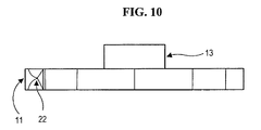
- FIG. 10 illustrates a top view of the counterclockwise blade ( 14 ) showing cutting extension ( 11 ) having sharp end ( 22 ) and control nut ( 13 ).
- FIG. 11 illustrates a perspective view of the counterclockwise blade ( 14 ).
- FIG. 12 illustrates a preferred embodiment of an insertion instrument for the housing. Prongs ( 15 ) fit inside the lateral walls ( 5 ) of the housing but clear the central opening ( 16 ) occupied by the blades ( 14 ).
- FIG. 13 illustrates a preferred method of placing the housing into a collapsed disk space ( 2 ) between vertebrae ( 1 ).
- FIG. 14 illustrates a housing inside an expanded disk space ( 2 ).
- FIG. 15 illustrates a preferred embodiment of a blade introducer having a receptacle ( 17 ) for the control nut ( 13 ) and central opening ( 18 ) for the shaft ( 10 ).
- FIG. 16 illustrates a blade ( 14 ) of FIG. 8 introduced horizontally into the housing of FIG. 7 using the blade introducer of FIG. 15 .
- FIG. 17 illustrates a blade ( 14 ) rotated vertically with cutting extensions ( 11 ) piercing vertebral endplates and hooking into vertebrae ( 1 ).
- FIG. 18 illustrates an alternative embodiment of a blade ( 14 ) having central opening ( 12 ) and control openings ( 19 ) on opposing sides of the central opening ( 12 ) to rotate the blade ( 14 ) about the shaft ( 10 ). These blades ( 14 ) are preloaded into the housing prior to placement of the housing into the disk space ( 2 ).
- FIG. 19 illustrates a transparent housing and central shaft ( 10 ) with pre-loaded blades ( 14 ) showing front two blades rotated into final vertical position.
- FIG. 20 illustrates a blade rotating tool that fits into control openings ( 19 ) of clockwise and counterclockwise blades ( 14 ) with prongs ( 20 ) of the rotating tool engaging and rotating the first three blades via the control openings ( 19 ).
- An implant device for reconstruction, fixation and bone fusion of bone vertebrae through an anterior approach to the human spine This implant device enables rigid fixation in all planes of motion including extension of the spine, it possesses structural characteristics necessary to reconstruct and maintain disk height, it provides space for bone grafting material and produces a plurality of perforations through endplates above and below to enhance bony fusion.
- the implant device consists of the outer structure or shell which is designed to conform to the disk space, provide openings for bony ingrowths and maintain the disk height by providing adequate structural strength and sufficient weight bearing surface.
- the shell or housing contains a shaft ( 10 ) which runs through its central axis from the back ( 9 ) to the front ( 8 ) and is fixed to the shell ( FIG. 7 ).
- the shell is impacted into the disk space ( FIG. 14 ) using the shell introducer ( FIG. 13 ).
- the shell introducer includes prongs ( 15 ) that fit inside the sides ( 5 ) of the shell but is open ( 16 ) in the center to allow for blades ( FIG. 12 ).
- FIG. 11 Individual blades ( FIG. 11 ) are selected, mounted onto the introducer ( FIG. 15 ) and threaded onto the shaft ( 10 ) in horizontal orientation ( FIG. 16 ).
- the blade is placed as deep as it can go and then rotated into vertical orientation breaking the endplate and hooking into the vertebra ( 1 ) ( FIG. 17 ).
- the blades alternate between clockwise and counterclockwise orientation. Variable size blades can be selected to better approximate the configuration of the disk space.
- alternating clockwise and counterclockwise blades are pre-loaded onto the shaft ( 10 ) and inside the housing ( FIG. 19 ).
- the blades include a central opening ( 12 ) and control openings ( 19 ) on opposing sides of the central opening ( 12 ) to rotate the blades about the shaft ( 10 ).
- a blade rotating tool with prongs ( 20 ) engaging the control openings ( 19 ) ( FIG. 20 ) engaging the blades are rotated sequentially going from superficial to deep.
- the housing expands horizontally and contains two shafts, which separate from each other upon expansion of the housing.
- preloaded clockwise and counterclockwise blades threaded on different shafts imbricate between each other. After the housing is expanded, the blades are pulled apart.
- a body ( 14 ) of a blade is configured as an oval so that the disk space is expanded as a blade is rotated.
Abstract
Description
Claims (16)
Priority Applications (2)
| Application Number | Priority Date | Filing Date | Title |
|---|---|---|---|
| US14/719,895 US9463096B2 (en) | 2005-12-29 | 2015-05-22 | Apparatus for anterior intervertebral spinal fixation and fusion |
| US15/289,591 US10292829B2 (en) | 2005-12-29 | 2016-10-10 | Apparatus and method for anterior intervertebral spinal fixation and fusion |
Applications Claiming Priority (4)
| Application Number | Priority Date | Filing Date | Title |
|---|---|---|---|
| US11/321,936 US7594932B2 (en) | 2005-12-29 | 2005-12-29 | Apparatus for anterior intervertebral spinal fixation and fusion |
| US12/567,691 US8070819B2 (en) | 2005-12-29 | 2009-09-25 | Apparatus and method for anterior intervertebral spinal fixation and fusion |
| US13/335,382 US9039770B2 (en) | 2005-12-29 | 2011-12-05 | Apparatus for anterior intervertebral spinal fixation and fusion |
| US14/719,895 US9463096B2 (en) | 2005-12-29 | 2015-05-22 | Apparatus for anterior intervertebral spinal fixation and fusion |
Related Parent Applications (1)
| Application Number | Title | Priority Date | Filing Date |
|---|---|---|---|
| US13/335,382 Division US9039770B2 (en) | 2005-12-29 | 2011-12-05 | Apparatus for anterior intervertebral spinal fixation and fusion |
Related Child Applications (1)
| Application Number | Title | Priority Date | Filing Date |
|---|---|---|---|
| US15/289,591 Continuation US10292829B2 (en) | 2005-12-29 | 2016-10-10 | Apparatus and method for anterior intervertebral spinal fixation and fusion |
Publications (2)
| Publication Number | Publication Date |
|---|---|
| US20150265416A1 US20150265416A1 (en) | 2015-09-24 |
| US9463096B2 true US9463096B2 (en) | 2016-10-11 |
Family
ID=38228790
Family Applications (5)
| Application Number | Title | Priority Date | Filing Date |
|---|---|---|---|
| US11/321,936 Active 2027-02-15 US7594932B2 (en) | 2005-12-29 | 2005-12-29 | Apparatus for anterior intervertebral spinal fixation and fusion |
| US12/567,691 Expired - Fee Related US8070819B2 (en) | 2005-12-29 | 2009-09-25 | Apparatus and method for anterior intervertebral spinal fixation and fusion |
| US13/335,382 Expired - Fee Related US9039770B2 (en) | 2005-12-29 | 2011-12-05 | Apparatus for anterior intervertebral spinal fixation and fusion |
| US14/719,895 Active US9463096B2 (en) | 2005-12-29 | 2015-05-22 | Apparatus for anterior intervertebral spinal fixation and fusion |
| US15/289,591 Expired - Fee Related US10292829B2 (en) | 2005-12-29 | 2016-10-10 | Apparatus and method for anterior intervertebral spinal fixation and fusion |
Family Applications Before (3)
| Application Number | Title | Priority Date | Filing Date |
|---|---|---|---|
| US11/321,936 Active 2027-02-15 US7594932B2 (en) | 2005-12-29 | 2005-12-29 | Apparatus for anterior intervertebral spinal fixation and fusion |
| US12/567,691 Expired - Fee Related US8070819B2 (en) | 2005-12-29 | 2009-09-25 | Apparatus and method for anterior intervertebral spinal fixation and fusion |
| US13/335,382 Expired - Fee Related US9039770B2 (en) | 2005-12-29 | 2011-12-05 | Apparatus for anterior intervertebral spinal fixation and fusion |
Family Applications After (1)
| Application Number | Title | Priority Date | Filing Date |
|---|---|---|---|
| US15/289,591 Expired - Fee Related US10292829B2 (en) | 2005-12-29 | 2016-10-10 | Apparatus and method for anterior intervertebral spinal fixation and fusion |
Country Status (3)
| Country | Link |
|---|---|
| US (5) | US7594932B2 (en) |
| EP (1) | EP1996093B1 (en) |
| WO (1) | WO2007079021A2 (en) |
Cited By (1)
| Publication number | Priority date | Publication date | Assignee | Title |
|---|---|---|---|---|
| US20190090922A1 (en) * | 2017-09-22 | 2019-03-28 | Howmedica Osteonics Corp. | Distal Radius Wedge Screw |
Families Citing this family (149)
| Publication number | Priority date | Publication date | Assignee | Title |
|---|---|---|---|---|
| FR2897259B1 (en) | 2006-02-15 | 2008-05-09 | Ldr Medical Soc Par Actions Si | INTERSOMATIC TRANSFORAMINAL CAGE WITH INTERBREBAL FUSION GRAFT AND CAGE IMPLANTATION INSTRUMENT |
| FR2824261B1 (en) | 2001-05-04 | 2004-05-28 | Ldr Medical | INTERVERTEBRAL DISC PROSTHESIS AND IMPLEMENTATION METHOD AND TOOLS |
| FR2827156B1 (en) | 2001-07-13 | 2003-11-14 | Ldr Medical | VERTEBRAL CAGE DEVICE WITH MODULAR FASTENING |
| AR038680A1 (en) | 2002-02-19 | 2005-01-26 | Synthes Ag | INTERVERTEBRAL IMPLANT |
| FR2846550B1 (en) | 2002-11-05 | 2006-01-13 | Ldr Medical | INTERVERTEBRAL DISC PROSTHESIS |
| US7828849B2 (en) | 2003-02-03 | 2010-11-09 | Warsaw Orthopedic, Inc. | Expanding interbody implant and articulating inserter and method |
| CA2515247C (en) | 2003-02-06 | 2010-10-05 | Synthes (U.S.A.) | Intervertebral implant |
| US7819903B2 (en) | 2003-03-31 | 2010-10-26 | Depuy Spine, Inc. | Spinal fixation plate |
| CN101961270B (en) | 2004-02-04 | 2016-08-10 | Ldr医学公司 | Intervertebral disk prosthesis |
| FR2865629B1 (en) | 2004-02-04 | 2007-01-26 | Ldr Medical | INTERVERTEBRAL DISC PROSTHESIS |
| FR2869528B1 (en) | 2004-04-28 | 2007-02-02 | Ldr Medical | INTERVERTEBRAL DISC PROSTHESIS |
| WO2006034436A2 (en) | 2004-09-21 | 2006-03-30 | Stout Medical Group, L.P. | Expandable support device and method of use |
| EP1639968A1 (en) * | 2004-09-23 | 2006-03-29 | Cervitech, Inc. | Implant with a part to be inserted and anchored in a bone cavity |
| US8597360B2 (en) * | 2004-11-03 | 2013-12-03 | Neuropro Technologies, Inc. | Bone fusion device |
| US20060095136A1 (en) * | 2004-11-03 | 2006-05-04 | Mcluen Design, Inc. | Bone fusion device |
| ATE524121T1 (en) | 2004-11-24 | 2011-09-15 | Abdou Samy | DEVICES FOR PLACING AN ORTHOPEDIC INTERVERTEBRAL IMPLANT |
| FR2879436B1 (en) | 2004-12-22 | 2007-03-09 | Ldr Medical | INTERVERTEBRAL DISC PROSTHESIS |
| JP5081822B2 (en) | 2005-07-14 | 2012-11-28 | スタウト メディカル グループ,エル.ピー. | Expandable support device and system |
| FR2891135B1 (en) | 2005-09-23 | 2008-09-12 | Ldr Medical Sarl | INTERVERTEBRAL DISC PROSTHESIS |
| FR2893838B1 (en) | 2005-11-30 | 2008-08-08 | Ldr Medical Soc Par Actions Si | PROSTHESIS OF INTERVERTEBRAL DISC AND INSTRUMENTATION OF INSERTION OF THE PROSTHESIS BETWEEN VERTEBRATES |
| US7594932B2 (en) * | 2005-12-29 | 2009-09-29 | International Spinal Innovations, Llc | Apparatus for anterior intervertebral spinal fixation and fusion |
| WO2007098288A2 (en) | 2006-02-27 | 2007-08-30 | Synthes (U.S.A.) | Intervertebral implant with fixation geometry |
| US8361116B2 (en) | 2006-03-24 | 2013-01-29 | U.S. Spine, Inc. | Non-pedicle based interspinous spacer |
| US8303660B1 (en) | 2006-04-22 | 2012-11-06 | Samy Abdou | Inter-vertebral disc prosthesis with variable rotational stop and methods of use |
| US8477658B2 (en) * | 2006-04-25 | 2013-07-02 | The Hong Kong University Of Science And Technology | Intelligent peer-to-peer media streaming |
| JP5542273B2 (en) | 2006-05-01 | 2014-07-09 | スタウト メディカル グループ,エル.ピー. | Expandable support device and method of use |
| US8771355B2 (en) * | 2006-05-26 | 2014-07-08 | M. S. Abdou | Inter-vertebral disc motion devices and methods of use |
| WO2008021319A2 (en) | 2006-08-11 | 2008-02-21 | Abdou M Samy | Spinal motion preservation devices and methods of use |
| US9526525B2 (en) | 2006-08-22 | 2016-12-27 | Neuropro Technologies, Inc. | Percutaneous system for dynamic spinal stabilization |
| WO2008073447A2 (en) | 2006-12-11 | 2008-06-19 | Abdou M Samy | Dynamic spinal stabilization systems and methods of use |
| US9039768B2 (en) | 2006-12-22 | 2015-05-26 | Medos International Sarl | Composite vertebral spacers and instrument |
| US8465546B2 (en) | 2007-02-16 | 2013-06-18 | Ldr Medical | Intervertebral disc prosthesis insertion assemblies |
| US8075593B2 (en) * | 2007-05-01 | 2011-12-13 | Spinal Simplicity Llc | Interspinous implants and methods for implanting same |
| US8142479B2 (en) * | 2007-05-01 | 2012-03-27 | Spinal Simplicity Llc | Interspinous process implants having deployable engagement arms |
| FR2916956B1 (en) | 2007-06-08 | 2012-12-14 | Ldr Medical | INTERSOMATIC CAGE, INTERVERTEBRAL PROSTHESIS, ANCHORING DEVICE AND IMPLANTATION INSTRUMENTATION |
| US10342674B2 (en) | 2007-07-02 | 2019-07-09 | Theken Spine, Llc | Spinal cage having deployable member |
| US8545562B1 (en) | 2007-07-02 | 2013-10-01 | Theken Spine, Llc | Deployable member for use with an intervertebral cage |
| US8292958B1 (en) | 2007-07-02 | 2012-10-23 | Theken Spine, Llc | Spinal cage having deployable member |
| US8142508B1 (en) | 2007-07-02 | 2012-03-27 | Theken Spine, Llc | Spinal cage having deployable member which is removable |
| US8864829B1 (en) | 2007-07-02 | 2014-10-21 | Theken Spine, Llc | Spinal cage having deployable member |
| US8167950B2 (en) | 2007-10-11 | 2012-05-01 | International Spinal Innovations, Llc | Minimally invasive lateral intervertbral fixation system, device and method |
| US8267997B2 (en) | 2007-11-12 | 2012-09-18 | Theken Spine, Llc | Vertebral interbody compression implant |
| BRPI0820172A2 (en) | 2007-11-16 | 2015-06-16 | Synthes Gmbh | Low Profile Intervertebral Implant |
| US20090248092A1 (en) | 2008-03-26 | 2009-10-01 | Jonathan Bellas | Posterior Intervertebral Disc Inserter and Expansion Techniques |
| FR2930426B1 (en) * | 2008-04-29 | 2011-04-29 | Hassan Razian | INTERSOMATIC CAGE |
| US20100010633A1 (en) * | 2008-07-10 | 2010-01-14 | Kyphon Sarl | Deployable Arc Fusion Cage and Methods Associated Therewith |
| BRPI0921486A2 (en) | 2008-11-07 | 2019-09-10 | Synthes Gmbh | vertebral intercorporeal unit of spacer and coupled plate |
| WO2010056895A1 (en) | 2008-11-12 | 2010-05-20 | Stout Medical Group, L.P. | Fixation device and method |
| US20100211176A1 (en) | 2008-11-12 | 2010-08-19 | Stout Medical Group, L.P. | Fixation device and method |
| US9861399B2 (en) | 2009-03-13 | 2018-01-09 | Spinal Simplicity, Llc | Interspinous process implant having a body with a removable end portion |
| US9757164B2 (en) | 2013-01-07 | 2017-09-12 | Spinal Simplicity Llc | Interspinous process implant having deployable anchor blades |
| US9526620B2 (en) | 2009-03-30 | 2016-12-27 | DePuy Synthes Products, Inc. | Zero profile spinal fusion cage |
| US8641766B2 (en) * | 2009-04-15 | 2014-02-04 | DePuy Synthes Products, LLC | Arcuate fixation member |
| US9408715B2 (en) | 2009-04-15 | 2016-08-09 | DePuy Synthes Products, Inc. | Arcuate fixation member |
| US20110029086A1 (en) * | 2009-07-29 | 2011-02-03 | Glazer Paul A | Lumbar jack implant |
| US10441433B2 (en) * | 2009-08-06 | 2019-10-15 | Alphatec Spine, Inc. | Stand-alone interbody fixation system |
| US8328870B2 (en) * | 2009-08-06 | 2012-12-11 | Alphatec Spine, Inc. | Stand-alone interbody fixation system |
| US20110046740A1 (en) * | 2009-08-24 | 2011-02-24 | UniMed Investment Inc. | Spinal implants, surgical instrument sets and methods of using the same |
| US9814494B2 (en) | 2009-09-03 | 2017-11-14 | Minsurg International, Inc. | Surgical implant device and surgical implant insertion assembly for the translation and fusion of a facet joint of the spine |
| US8814907B2 (en) * | 2009-09-03 | 2014-08-26 | Lrad, Llc | Surgical implant device for the translation and fusion of a facet joint of the spine |
| EP2477579B1 (en) | 2009-09-17 | 2015-12-23 | LDR Holding Corporation | Intervertebral implant having extendable bone fixation members |
| US8764806B2 (en) | 2009-12-07 | 2014-07-01 | Samy Abdou | Devices and methods for minimally invasive spinal stabilization and instrumentation |
| US9393129B2 (en) | 2009-12-10 | 2016-07-19 | DePuy Synthes Products, Inc. | Bellows-like expandable interbody fusion cage |
| US9480511B2 (en) | 2009-12-17 | 2016-11-01 | Engage Medical Holdings, Llc | Blade fixation for ankle fusion and arthroplasty |
| BR112012016296A2 (en) | 2009-12-31 | 2017-03-21 | Ldr Medical | anchorage device, intervertebral implant and implantation instrument |
| US8469959B2 (en) * | 2010-02-11 | 2013-06-25 | Warsaw Orthopedic, Inc. | Bone preparation device |
| WO2011116136A1 (en) | 2010-03-16 | 2011-09-22 | Pinnacle Spine Group, Llc | Intervertebral implants and graft delivery systems and methods |
| US20110225704A1 (en) * | 2010-03-18 | 2011-09-22 | Adam Luchowski | Video game remote controller glove attachment device |
| CA2811327C (en) * | 2010-09-21 | 2018-05-29 | Spinewelding Ag | Device for repairing a human or animal joint |
| US20120078372A1 (en) | 2010-09-23 | 2012-03-29 | Thomas Gamache | Novel implant inserter having a laterally-extending dovetail engagement feature |
| US11529241B2 (en) | 2010-09-23 | 2022-12-20 | DePuy Synthes Products, Inc. | Fusion cage with in-line single piece fixation |
| US20120078373A1 (en) | 2010-09-23 | 2012-03-29 | Thomas Gamache | Stand alone intervertebral fusion device |
| FR2965169B1 (en) * | 2010-09-27 | 2012-09-21 | Hassan Razian | INTERVERTEBRAL CAGE. |
| US9149286B1 (en) | 2010-11-12 | 2015-10-06 | Flexmedex, LLC | Guidance tool and method for use |
| WO2012083205A1 (en) | 2010-12-16 | 2012-06-21 | Medicinelodge, Inc. Dba Imds Co-Innovation | Arthroplasty systems and methods |
| WO2012088238A2 (en) | 2010-12-21 | 2012-06-28 | Synthes Usa, Llc | Intervertebral implants, systems, and methods of use |
| US9241809B2 (en) | 2010-12-21 | 2016-01-26 | DePuy Synthes Products, Inc. | Intervertebral implants, systems, and methods of use |
| US9358122B2 (en) | 2011-01-07 | 2016-06-07 | K2M, Inc. | Interbody spacer |
| US8545563B2 (en) | 2011-02-02 | 2013-10-01 | DePuy Synthes Product, LLC | Intervertebral implant having extendable bone fixation members |
| WO2013008111A1 (en) * | 2011-07-14 | 2013-01-17 | Kamil Bal | Fixation system for spinal cages |
| WO2013023096A1 (en) | 2011-08-09 | 2013-02-14 | Neuropro Technologies, Inc. | Bone fusion device, system and method |
| WO2013023098A1 (en) | 2011-08-09 | 2013-02-14 | Neuropro Spinal Jaxx Inc. | Bone fusion device, apparatus and method |
| US10420654B2 (en) | 2011-08-09 | 2019-09-24 | Neuropro Technologies, Inc. | Bone fusion device, system and method |
| EP2747682A4 (en) | 2011-08-23 | 2015-01-21 | Flexmedex Llc | Tissue removal device and method |
| US9248028B2 (en) | 2011-09-16 | 2016-02-02 | DePuy Synthes Products, Inc. | Removable, bone-securing cover plate for intervertebral fusion cage |
| US10555821B2 (en) | 2011-09-21 | 2020-02-11 | Tov Inge Vestgaarden | Method and apparatus for spinal interbody fusion including fixation or locking plate |
| US20160106549A1 (en) | 2011-09-21 | 2016-04-21 | Vg Innovations, Llc | Interconnected Locking Plates for Adjacent Spinal Vertebral Bodies |
| US8845728B1 (en) | 2011-09-23 | 2014-09-30 | Samy Abdou | Spinal fixation devices and methods of use |
| US9615856B2 (en) | 2011-11-01 | 2017-04-11 | Imds Llc | Sacroiliac fusion cage |
| US9254130B2 (en) | 2011-11-01 | 2016-02-09 | Hyun Bae | Blade anchor systems for bone fusion |
| US9380932B1 (en) | 2011-11-02 | 2016-07-05 | Pinnacle Spine Group, Llc | Retractor devices for minimally invasive access to the spine |
| US9526627B2 (en) | 2011-11-17 | 2016-12-27 | Exactech, Inc. | Expandable interbody device system and method |
| US9198764B2 (en) * | 2012-01-31 | 2015-12-01 | Blackstone Medical, Inc. | Intervertebral disc prosthesis and method |
| US20130226240A1 (en) | 2012-02-22 | 2013-08-29 | Samy Abdou | Spinous process fixation devices and methods of use |
| FR2987256B1 (en) | 2012-02-24 | 2014-08-08 | Ldr Medical | ANCHORING DEVICE FOR INTERVERTEBRAL IMPLANT, INTERVERTEBRAL IMPLANT AND IMPLANTATION INSTRUMENTATION |
| US9271836B2 (en) | 2012-03-06 | 2016-03-01 | DePuy Synthes Products, Inc. | Nubbed plate |
| EP2638880A1 (en) * | 2012-03-16 | 2013-09-18 | Hassan Razian | Intervertebral cage |
| US10238382B2 (en) | 2012-03-26 | 2019-03-26 | Engage Medical Holdings, Llc | Blade anchor for foot and ankle |
| US9693876B1 (en) | 2012-03-30 | 2017-07-04 | Ali H. MESIWALA | Spinal fusion implant and related methods |
| US8900310B2 (en) | 2012-04-05 | 2014-12-02 | Zimmer Spine, Inc. | Interbody spacer |
| US9114020B2 (en) | 2012-04-13 | 2015-08-25 | Marc Arginteanu | Device and method for spinal fusion surgery |
| US10159583B2 (en) | 2012-04-13 | 2018-12-25 | Neuropro Technologies, Inc. | Bone fusion device |
| US9532883B2 (en) | 2012-04-13 | 2017-01-03 | Neuropro Technologies, Inc. | Bone fusion device |
| US9198767B2 (en) | 2012-08-28 | 2015-12-01 | Samy Abdou | Devices and methods for spinal stabilization and instrumentation |
| US9987142B2 (en) | 2012-08-31 | 2018-06-05 | Institute for Musculoskeletal Science and Education, Ltd. | Fixation devices for anterior lumbar or cervical interbody fusion |
| US8882818B1 (en) | 2012-09-24 | 2014-11-11 | Vg Innovations, Llc | Method for deploying a fusion device for sacroiliac joint fusion |
| US9320617B2 (en) | 2012-10-22 | 2016-04-26 | Cogent Spine, LLC | Devices and methods for spinal stabilization and instrumentation |
| US10182921B2 (en) | 2012-11-09 | 2019-01-22 | DePuy Synthes Products, Inc. | Interbody device with opening to allow packing graft and other biologics |
| US9883874B1 (en) | 2013-03-08 | 2018-02-06 | Vg Innovations, Llc | Tool and method for implanting fusion device into sacroiliac joint |
| US9456908B2 (en) | 2013-03-12 | 2016-10-04 | Coorstek Medical Llc | Fusion cage |
| WO2014159739A1 (en) | 2013-03-14 | 2014-10-02 | Pinnacle Spine Group, Llc | Interbody implants and graft delivery systems |
| US9301849B2 (en) | 2013-03-14 | 2016-04-05 | Warsaw Orthopedic, Inc. | Endplate punch template and method of use |
| CA2906846C (en) * | 2013-03-15 | 2021-10-26 | Lifenet Health | Medical implant for fixation and integration with hard tissue |
| US10098757B2 (en) | 2013-03-15 | 2018-10-16 | Neuropro Technologies Inc. | Bodiless bone fusion device, apparatus and method |
| FR3005569B1 (en) | 2013-05-16 | 2021-09-03 | Ldr Medical | VERTEBRAL IMPLANT, VERTEBRAL IMPLANT FIXATION DEVICE AND IMPLANTATION INSTRUMENTATION |
| US9283091B2 (en) * | 2013-10-07 | 2016-03-15 | Warsaw Orthopedic, Inc. | Spinal implant system and method |
| FR3016793B1 (en) | 2014-01-30 | 2021-05-07 | Ldr Medical | ANCHORING DEVICE FOR SPINAL IMPLANT, SPINAL IMPLANT AND IMPLANTATION INSTRUMENTATION |
| US9517144B2 (en) | 2014-04-24 | 2016-12-13 | Exactech, Inc. | Limited profile intervertebral implant with incorporated fastening mechanism |
| US10398565B2 (en) | 2014-04-24 | 2019-09-03 | Choice Spine, Llc | Limited profile intervertebral implant with incorporated fastening and locking mechanism |
| FR3020756B1 (en) | 2014-05-06 | 2022-03-11 | Ldr Medical | VERTEBRAL IMPLANT, VERTEBRAL IMPLANT FIXATION DEVICE AND IMPLANT INSTRUMENTATION |
| WO2015185503A1 (en) * | 2014-06-06 | 2015-12-10 | Koninklijke Philips N.V. | Imaging system for a vertebral level |
| US20160045326A1 (en) * | 2014-08-18 | 2016-02-18 | Eric Hansen | Interbody spacer system |
| US9867718B2 (en) | 2014-10-22 | 2018-01-16 | DePuy Synthes Products, Inc. | Intervertebral implants, systems, and methods of use |
| US9707100B2 (en) | 2015-06-25 | 2017-07-18 | Institute for Musculoskeletal Science and Education, Ltd. | Interbody fusion device and system for implantation |
| US10857003B1 (en) | 2015-10-14 | 2020-12-08 | Samy Abdou | Devices and methods for vertebral stabilization |
| WO2017143330A1 (en) * | 2016-02-18 | 2017-08-24 | K2M, Inc. | Surgical fixation assemblies and methods of use |
| AU2017281696B2 (en) | 2016-06-23 | 2022-06-23 | VGI Medical, LLC | Method and apparatus for spinal facet fusion |
| US10390955B2 (en) | 2016-09-22 | 2019-08-27 | Engage Medical Holdings, Llc | Bone implants |
| US10307265B2 (en) | 2016-10-18 | 2019-06-04 | Institute for Musculoskeletal Science and Education, Ltd. | Implant with deployable blades |
| US10973648B1 (en) | 2016-10-25 | 2021-04-13 | Samy Abdou | Devices and methods for vertebral bone realignment |
| US10449060B2 (en) | 2016-10-25 | 2019-10-22 | Institute for Musculoskeletal Science and Education, Ltd. | Spinal fusion implant |
| US10744000B1 (en) | 2016-10-25 | 2020-08-18 | Samy Abdou | Devices and methods for vertebral bone realignment |
| US10405992B2 (en) | 2016-10-25 | 2019-09-10 | Institute for Musculoskeletal Science and Education, Ltd. | Spinal fusion implant |
| US10973657B2 (en) | 2017-01-18 | 2021-04-13 | Neuropro Technologies, Inc. | Bone fusion surgical system and method |
| US10111760B2 (en) | 2017-01-18 | 2018-10-30 | Neuropro Technologies, Inc. | Bone fusion system, device and method including a measuring mechanism |
| US10213321B2 (en) | 2017-01-18 | 2019-02-26 | Neuropro Technologies, Inc. | Bone fusion system, device and method including delivery apparatus |
| US10729560B2 (en) | 2017-01-18 | 2020-08-04 | Neuropro Technologies, Inc. | Bone fusion system, device and method including an insertion instrument |
| US11540928B2 (en) | 2017-03-03 | 2023-01-03 | Engage Uni Llc | Unicompartmental knee arthroplasty |
| US10456272B2 (en) | 2017-03-03 | 2019-10-29 | Engage Uni Llc | Unicompartmental knee arthroplasty |
| US10470894B2 (en) | 2017-04-06 | 2019-11-12 | Warsaw Orthopedic, Inc. | Expanding interbody implant and articulating inserter and methods of use |
| US10940016B2 (en) | 2017-07-05 | 2021-03-09 | Medos International Sarl | Expandable intervertebral fusion cage |
| US10772738B2 (en) | 2017-07-18 | 2020-09-15 | Blue Sky Technologies, LLC | Joint arthrodesis system |
| US11419736B2 (en) | 2017-07-18 | 2022-08-23 | Blue Sky Technologies, LLC | Joint implant |
| US11090094B2 (en) * | 2018-06-01 | 2021-08-17 | Ehsan JAZINI | System and method for facilitating osteotomy of the pelvic |
| US10849758B2 (en) | 2018-08-22 | 2020-12-01 | Institute for Musculoskeletal Science and Education, Ltd. | Spinal fusion implant |
| US11179248B2 (en) | 2018-10-02 | 2021-11-23 | Samy Abdou | Devices and methods for spinal implantation |
| JP2022521017A (en) | 2019-02-24 | 2022-04-04 | ブルー スカイ テクノロジー、エルエルシー | Bone graft |
| US20230201004A1 (en) * | 2019-05-24 | 2023-06-29 | Blue Sky Technologies, LLC | Joint Implant |
| WO2023216003A1 (en) * | 2022-05-13 | 2023-11-16 | Caratsch Alexander | Flexible interbody cage |
Citations (18)
| Publication number | Priority date | Publication date | Assignee | Title |
|---|---|---|---|---|
| US2864421A (en) * | 1956-06-27 | 1958-12-16 | Cincinnati Butchers Supply Co | Double blade knife |
| US5522441A (en) * | 1994-08-10 | 1996-06-04 | Western Cutterheads, Inc. | Wood lathe tooling |
| US6012372A (en) * | 1996-01-18 | 2000-01-11 | Laster; James E. | Adjustable arbor and cutting elements |
| US6159211A (en) * | 1998-10-22 | 2000-12-12 | Depuy Acromed, Inc. | Stackable cage system for corpectomy/vertebrectomy |
| US6227093B1 (en) * | 1999-12-21 | 2001-05-08 | Bernard J. Rensky, Jr. | Pizza docking device |
| US6302914B1 (en) * | 1995-06-07 | 2001-10-16 | Gary Karlin Michelson | Lordotic interbody spinal fusion implants |
| US6443990B1 (en) * | 1997-08-06 | 2002-09-03 | Synthes (U.S.A.) | Adjustable intervertebral implant |
| US6447547B1 (en) * | 1988-06-28 | 2002-09-10 | Sofamor Danek Group, Inc. | Artificial spinal fusion implants |
| US20020143401A1 (en) * | 2001-03-27 | 2002-10-03 | Michelson Gary K. | Radially expanding interbody spinal fusion implants, instrumentation, and methods of insertion |
| US20030004576A1 (en) * | 2001-06-28 | 2003-01-02 | Thalgott John S. | Modular anatomic fusion device |
| US6527803B1 (en) * | 1998-06-23 | 2003-03-04 | Dimso (Distribution Medicale Du Sud-Ouest) | Intersomatic spine implant having anchoring elements |
| US20030187436A1 (en) * | 1999-07-01 | 2003-10-02 | Ciaran Bolger | Interbody spinal stabilization cage and spinal stabilization method |
| US20040138752A1 (en) * | 2002-02-02 | 2004-07-15 | Michelson Gary K. | Spinal fusion implant having deployable bone engaging projections |
| US6824564B2 (en) * | 1997-04-25 | 2004-11-30 | Stryker France, Sas | Two-part intersomatic implant |
| US7238203B2 (en) * | 2001-12-12 | 2007-07-03 | Vita Special Purpose Corporation | Bioactive spinal implants and method of manufacture thereof |
| US20070270968A1 (en) * | 2004-02-10 | 2007-11-22 | Baynham Bret O | Plif opposing wedge ramp |
| US20080255666A1 (en) * | 2007-04-13 | 2008-10-16 | Depuy Spine, Inc. | Facet fixation and fusion wedge and method of use |
| US7594932B2 (en) * | 2005-12-29 | 2009-09-29 | International Spinal Innovations, Llc | Apparatus for anterior intervertebral spinal fixation and fusion |
Family Cites Families (6)
| Publication number | Priority date | Publication date | Assignee | Title |
|---|---|---|---|---|
| US1217326A (en) * | 1916-05-13 | 1917-02-27 | Joseph Meinecke | Rotary cutter for sugar-cane and the like. |
| US2815077A (en) * | 1954-02-12 | 1957-12-03 | American Can Co | Slitter element mountings for sheet slitting machines |
| US5254118A (en) | 1991-12-04 | 1993-10-19 | Srdjian Mirkovic | Three dimensional spine fixation system |
| US5683394A (en) * | 1995-09-29 | 1997-11-04 | Advanced Spine Fixation Systems, Inc. | Fusion mass constrainer |
| US6241769B1 (en) * | 1998-05-06 | 2001-06-05 | Cortek, Inc. | Implant for spinal fusion |
| US20050143825A1 (en) * | 2002-07-09 | 2005-06-30 | Albert Enayati | Intervertebral prosthesis |
-
2005
- 2005-12-29 US US11/321,936 patent/US7594932B2/en active Active
-
2006
- 2006-12-19 EP EP06845994.0A patent/EP1996093B1/en not_active Not-in-force
- 2006-12-19 WO PCT/US2006/048990 patent/WO2007079021A2/en active Application Filing
-
2009
- 2009-09-25 US US12/567,691 patent/US8070819B2/en not_active Expired - Fee Related
-
2011
- 2011-12-05 US US13/335,382 patent/US9039770B2/en not_active Expired - Fee Related
-
2015
- 2015-05-22 US US14/719,895 patent/US9463096B2/en active Active
-
2016
- 2016-10-10 US US15/289,591 patent/US10292829B2/en not_active Expired - Fee Related
Patent Citations (23)
| Publication number | Priority date | Publication date | Assignee | Title |
|---|---|---|---|---|
| US2864421A (en) * | 1956-06-27 | 1958-12-16 | Cincinnati Butchers Supply Co | Double blade knife |
| US6447547B1 (en) * | 1988-06-28 | 2002-09-10 | Sofamor Danek Group, Inc. | Artificial spinal fusion implants |
| US5522441A (en) * | 1994-08-10 | 1996-06-04 | Western Cutterheads, Inc. | Wood lathe tooling |
| US6302914B1 (en) * | 1995-06-07 | 2001-10-16 | Gary Karlin Michelson | Lordotic interbody spinal fusion implants |
| US6447544B1 (en) * | 1995-06-07 | 2002-09-10 | Gary Karlin Michelson | Lordotic interbody spinal fusion implants |
| US6012372A (en) * | 1996-01-18 | 2000-01-11 | Laster; James E. | Adjustable arbor and cutting elements |
| US6824564B2 (en) * | 1997-04-25 | 2004-11-30 | Stryker France, Sas | Two-part intersomatic implant |
| US6443990B1 (en) * | 1997-08-06 | 2002-09-03 | Synthes (U.S.A.) | Adjustable intervertebral implant |
| US6527803B1 (en) * | 1998-06-23 | 2003-03-04 | Dimso (Distribution Medicale Du Sud-Ouest) | Intersomatic spine implant having anchoring elements |
| US6159211A (en) * | 1998-10-22 | 2000-12-12 | Depuy Acromed, Inc. | Stackable cage system for corpectomy/vertebrectomy |
| US6770096B2 (en) * | 1999-07-01 | 2004-08-03 | Spinevision S.A. | Interbody spinal stabilization cage and spinal stabilization method |
| US20030187436A1 (en) * | 1999-07-01 | 2003-10-02 | Ciaran Bolger | Interbody spinal stabilization cage and spinal stabilization method |
| US6227093B1 (en) * | 1999-12-21 | 2001-05-08 | Bernard J. Rensky, Jr. | Pizza docking device |
| US20020143401A1 (en) * | 2001-03-27 | 2002-10-03 | Michelson Gary K. | Radially expanding interbody spinal fusion implants, instrumentation, and methods of insertion |
| US20030004576A1 (en) * | 2001-06-28 | 2003-01-02 | Thalgott John S. | Modular anatomic fusion device |
| US6558424B2 (en) * | 2001-06-28 | 2003-05-06 | Depuy Acromed | Modular anatomic fusion device |
| US7238203B2 (en) * | 2001-12-12 | 2007-07-03 | Vita Special Purpose Corporation | Bioactive spinal implants and method of manufacture thereof |
| US20040138752A1 (en) * | 2002-02-02 | 2004-07-15 | Michelson Gary K. | Spinal fusion implant having deployable bone engaging projections |
| US20070270968A1 (en) * | 2004-02-10 | 2007-11-22 | Baynham Bret O | Plif opposing wedge ramp |
| US7594932B2 (en) * | 2005-12-29 | 2009-09-29 | International Spinal Innovations, Llc | Apparatus for anterior intervertebral spinal fixation and fusion |
| US8070819B2 (en) * | 2005-12-29 | 2011-12-06 | Alphatec Spine, Inc. | Apparatus and method for anterior intervertebral spinal fixation and fusion |
| US9039770B2 (en) * | 2005-12-29 | 2015-05-26 | Alphatec Spine, Inc. | Apparatus for anterior intervertebral spinal fixation and fusion |
| US20080255666A1 (en) * | 2007-04-13 | 2008-10-16 | Depuy Spine, Inc. | Facet fixation and fusion wedge and method of use |
Cited By (2)
| Publication number | Priority date | Publication date | Assignee | Title |
|---|---|---|---|---|
| US20190090922A1 (en) * | 2017-09-22 | 2019-03-28 | Howmedica Osteonics Corp. | Distal Radius Wedge Screw |
| US10828077B2 (en) * | 2017-09-22 | 2020-11-10 | Howmedica Osteonics Corp. | Distal radius wedge screw |
Also Published As
| Publication number | Publication date |
|---|---|
| US20150265416A1 (en) | 2015-09-24 |
| US9039770B2 (en) | 2015-05-26 |
| US7594932B2 (en) | 2009-09-29 |
| US10292829B2 (en) | 2019-05-21 |
| EP1996093A4 (en) | 2012-03-28 |
| US20080132949A1 (en) | 2008-06-05 |
| US20100145458A1 (en) | 2010-06-10 |
| US20130006360A1 (en) | 2013-01-03 |
| EP1996093A2 (en) | 2008-12-03 |
| EP1996093B1 (en) | 2018-06-06 |
| US8070819B2 (en) | 2011-12-06 |
| WO2007079021A3 (en) | 2007-11-08 |
| US20170020682A1 (en) | 2017-01-26 |
| WO2007079021A2 (en) | 2007-07-12 |
Similar Documents
| Publication | Publication Date | Title |
|---|---|---|
| US9463096B2 (en) | Apparatus for anterior intervertebral spinal fixation and fusion | |
| US20220273459A1 (en) | Method and spacer device for spanning a space formed upon removal of an intervertebral disc | |
| US8029512B2 (en) | Spinal stabilization device and methods | |
| US7105023B2 (en) | Vertebral defect device | |
| US6579318B2 (en) | Intervertebral spacer | |
| EP2328495B1 (en) | Intervertebral fusion implant | |
| US20060276790A1 (en) | Minimally invasive facet joint repair | |
| US20050010292A1 (en) | Method for correcting a deformity in the spinal column and its corresponding implant | |
| EP1849437A2 (en) | Dual composition vertebral fixation device | |
| KR20140019773A (en) | Intervertebral device and methods of use | |
| JP2002543858A (en) | Box and cage for interbody fusion | |
| EP2603176B1 (en) | C1-c2 implant | |
| AU2008282493A1 (en) | Inter-body implantation system and method | |
| US10420652B2 (en) | Bone scaffold improvements | |
| US9855149B2 (en) | Interbody fusion device | |
| NZ731593B2 (en) | Bone scaffold improvements |
Legal Events
| Date | Code | Title | Description |
|---|---|---|---|
| AS | Assignment |
Owner name: ALPHATEC SPINE, INC., CALIFORNIA Free format text: ASSIGNMENT OF ASSIGNORS INTEREST;ASSIGNORS:AFERZON, JOSEPH;AFERZON, JOSHUA;REEL/FRAME:036192/0750 Effective date: 20100118 |
|
| AS | Assignment |
Owner name: INTERNATIONAL SPINAL INNOVATIONS, CONNECTICUT Free format text: ASSIGNMENT OF ASSIGNORS INTEREST;ASSIGNORS:AFERZON, JOSEPH;AFERZON, JOSHUA MICHAEL;REEL/FRAME:036691/0763 Effective date: 20080509 |
|
| AS | Assignment |
Owner name: INTERNATIONAL SPINAL INNOVATIONS, CONNECTICUT Free format text: CORRECTIVE ASSIGNMENT TO CORRECT THE CHAIN OF TITLE BY REMOVING THE INADVERTENTLY FILED ASSIGNMENT TO ALPHATEC SPINE, INC. PREVIOUSLY RECORDED ON REEL 036192 FRAME 0750. ASSIGNOR(S) HEREBY CONFIRMS THE ASSIGNMENT TO INTERNATIONAL SPINAL INNOVATIONS;ASSIGNOR:INTERNATIONAL SPINAL INNOVATIONS;REEL/FRAME:037565/0227 Effective date: 20160120 |
|
| STCF | Information on status: patent grant |
Free format text: PATENTED CASE |
|
| AS | Assignment |
Owner name: GLOBUS MEDICAL, INC., PENNSYLVANIA Free format text: INTELLECTUAL PROPERTY SECURITY AGREEMENT;ASSIGNORS:ALPHATEC HOLDINGS, INC.;ALPHATEC SPINE, INC.;REEL/FRAME:040108/0202 Effective date: 20160901 |
|
| AS | Assignment |
Owner name: ALPHATEC HOLDINGS, INC., CALIFORNIA Free format text: RELEASE BY SECURED PARTY;ASSIGNOR:GLOBUS MEDICAL, INC.;REEL/FRAME:047485/0084 Effective date: 20181107 Owner name: ALPHATEC SPINE, INC., CALIFORNIA Free format text: RELEASE BY SECURED PARTY;ASSIGNOR:GLOBUS MEDICAL, INC.;REEL/FRAME:047485/0084 Effective date: 20181107 |
|
| AS | Assignment |
Owner name: SQUADRON MEDICAL FINANCE SOLUTIONS LLC, CONNECTICUT Free format text: SECURITY INTEREST;ASSIGNORS:ALPHATEC HOLDINGS, INC.;ALPHATEC SPINE, INC.;REEL/FRAME:047494/0562 Effective date: 20181106 Owner name: SQUADRON MEDICAL FINANCE SOLUTIONS LLC, CONNECTICU Free format text: SECURITY INTEREST;ASSIGNORS:ALPHATEC HOLDINGS, INC.;ALPHATEC SPINE, INC.;REEL/FRAME:047494/0562 Effective date: 20181106 |
|
| MAFP | Maintenance fee payment |
Free format text: PAYMENT OF MAINTENANCE FEE, 4TH YR, SMALL ENTITY (ORIGINAL EVENT CODE: M2551); ENTITY STATUS OF PATENT OWNER: SMALL ENTITY Year of fee payment: 4 |
|
| AS | Assignment |
Owner name: ALPHATEC HOLDINGS, INC., CALIFORNIA Free format text: RELEASE OF SECURITY INTEREST IN PATENT COLLATERAL AT REEL/FRAME NO. 47494/0562;ASSIGNOR:SQUADRON MEDICAL FINANCE SOLUTIONS LLC;REEL/FRAME:057177/0687 Effective date: 20210804 Owner name: ALPHATEC SPINE, INC., CALIFORNIA Free format text: RELEASE OF SECURITY INTEREST IN PATENT COLLATERAL AT REEL/FRAME NO. 47494/0562;ASSIGNOR:SQUADRON MEDICAL FINANCE SOLUTIONS LLC;REEL/FRAME:057177/0687 Effective date: 20210804 |