US9459515B2 - Adjustable camera mount for a vehicle windshield - Google Patents
Adjustable camera mount for a vehicle windshield Download PDFInfo
- Publication number
- US9459515B2 US9459515B2 US13/484,684 US201213484684A US9459515B2 US 9459515 B2 US9459515 B2 US 9459515B2 US 201213484684 A US201213484684 A US 201213484684A US 9459515 B2 US9459515 B2 US 9459515B2
- Authority
- US
- United States
- Prior art keywords
- camera
- image
- windshield
- vehicle
- exposure
- Prior art date
- Legal status (The legal status is an assumption and is not a legal conclusion. Google has not performed a legal analysis and makes no representation as to the accuracy of the status listed.)
- Active
Links
- 238000000034 method Methods 0.000 claims description 62
- 230000007246 mechanism Effects 0.000 claims description 9
- 238000001514 detection method Methods 0.000 description 45
- 239000011521 glass Substances 0.000 description 26
- 238000005192 partition Methods 0.000 description 22
- 230000004044 response Effects 0.000 description 19
- 238000002834 transmittance Methods 0.000 description 19
- 230000006870 function Effects 0.000 description 13
- 230000008859 change Effects 0.000 description 12
- 239000013598 vector Substances 0.000 description 12
- 238000013461 design Methods 0.000 description 10
- 238000012706 support-vector machine Methods 0.000 description 9
- 238000005286 illumination Methods 0.000 description 8
- 230000000875 corresponding effect Effects 0.000 description 7
- 125000001475 halogen functional group Chemical group 0.000 description 7
- 239000003550 marker Substances 0.000 description 7
- 229920006395 saturated elastomer Polymers 0.000 description 7
- 229910052736 halogen Inorganic materials 0.000 description 6
- 150000002367 halogens Chemical class 0.000 description 6
- 238000012986 modification Methods 0.000 description 6
- 230000004048 modification Effects 0.000 description 6
- 230000003287 optical effect Effects 0.000 description 6
- 238000010801 machine learning Methods 0.000 description 5
- 238000013507 mapping Methods 0.000 description 5
- 239000011159 matrix material Substances 0.000 description 5
- 238000012549 training Methods 0.000 description 5
- 238000013459 approach Methods 0.000 description 4
- 230000008901 benefit Effects 0.000 description 4
- 238000004519 manufacturing process Methods 0.000 description 4
- 238000005259 measurement Methods 0.000 description 4
- 238000000638 solvent extraction Methods 0.000 description 4
- 238000012360 testing method Methods 0.000 description 4
- 230000001133 acceleration Effects 0.000 description 3
- 238000005516 engineering process Methods 0.000 description 3
- 238000003384 imaging method Methods 0.000 description 3
- 230000001965 increasing effect Effects 0.000 description 3
- 238000009434 installation Methods 0.000 description 3
- 230000010354 integration Effects 0.000 description 3
- 230000008569 process Effects 0.000 description 3
- 238000001228 spectrum Methods 0.000 description 3
- XEEYBQQBJWHFJM-UHFFFAOYSA-N Iron Chemical compound [Fe] XEEYBQQBJWHFJM-UHFFFAOYSA-N 0.000 description 2
- 230000001419 dependent effect Effects 0.000 description 2
- 230000000694 effects Effects 0.000 description 2
- 239000003292 glue Substances 0.000 description 2
- 230000001902 propagating effect Effects 0.000 description 2
- 230000035945 sensitivity Effects 0.000 description 2
- 239000007787 solid Substances 0.000 description 2
- 229910052724 xenon Inorganic materials 0.000 description 2
- FHNFHKCVQCLJFQ-UHFFFAOYSA-N xenon atom Chemical compound [Xe] FHNFHKCVQCLJFQ-UHFFFAOYSA-N 0.000 description 2
- 241000238097 Callinectes sapidus Species 0.000 description 1
- 241001282110 Pagrus major Species 0.000 description 1
- 206010034960 Photophobia Diseases 0.000 description 1
- 230000004913 activation Effects 0.000 description 1
- 239000000853 adhesive Substances 0.000 description 1
- 230000001070 adhesive effect Effects 0.000 description 1
- 230000000295 complement effect Effects 0.000 description 1
- 230000005494 condensation Effects 0.000 description 1
- 238000009833 condensation Methods 0.000 description 1
- 238000012937 correction Methods 0.000 description 1
- 230000002596 correlated effect Effects 0.000 description 1
- 238000005314 correlation function Methods 0.000 description 1
- 230000003247 decreasing effect Effects 0.000 description 1
- 230000004069 differentiation Effects 0.000 description 1
- 230000002708 enhancing effect Effects 0.000 description 1
- 229920006332 epoxy adhesive Polymers 0.000 description 1
- 238000013213 extrapolation Methods 0.000 description 1
- 230000005294 ferromagnetic effect Effects 0.000 description 1
- 238000002329 infrared spectrum Methods 0.000 description 1
- 238000013101 initial test Methods 0.000 description 1
- 229910052742 iron Inorganic materials 0.000 description 1
- 238000005304 joining Methods 0.000 description 1
- 208000013469 light sensitivity Diseases 0.000 description 1
- 239000003595 mist Substances 0.000 description 1
- 238000012544 monitoring process Methods 0.000 description 1
- 238000005457 optimization Methods 0.000 description 1
- 238000012856 packing Methods 0.000 description 1
- 238000003909 pattern recognition Methods 0.000 description 1
- 230000000737 periodic effect Effects 0.000 description 1
- 239000000049 pigment Substances 0.000 description 1
- 238000000513 principal component analysis Methods 0.000 description 1
- 238000012545 processing Methods 0.000 description 1
- 230000009467 reduction Effects 0.000 description 1
- 230000002040 relaxant effect Effects 0.000 description 1
- 238000009877 rendering Methods 0.000 description 1
- 230000014624 response to red light Effects 0.000 description 1
- 230000002441 reversible effect Effects 0.000 description 1
- 238000009738 saturating Methods 0.000 description 1
- 238000000926 separation method Methods 0.000 description 1
- 238000011895 specific detection Methods 0.000 description 1
- 230000001360 synchronised effect Effects 0.000 description 1
- 230000007704 transition Effects 0.000 description 1
- 238000013519 translation Methods 0.000 description 1
- 239000002699 waste material Substances 0.000 description 1
- XLYOFNOQVPJJNP-UHFFFAOYSA-N water Substances O XLYOFNOQVPJJNP-UHFFFAOYSA-N 0.000 description 1
Images


Classifications
-
- G—PHYSICS
- G03—PHOTOGRAPHY; CINEMATOGRAPHY; ANALOGOUS TECHNIQUES USING WAVES OTHER THAN OPTICAL WAVES; ELECTROGRAPHY; HOLOGRAPHY
- G03B—APPARATUS OR ARRANGEMENTS FOR TAKING PHOTOGRAPHS OR FOR PROJECTING OR VIEWING THEM; APPARATUS OR ARRANGEMENTS EMPLOYING ANALOGOUS TECHNIQUES USING WAVES OTHER THAN OPTICAL WAVES; ACCESSORIES THEREFOR
- G03B17/00—Details of cameras or camera bodies; Accessories therefor
- G03B17/02—Bodies
-
- B—PERFORMING OPERATIONS; TRANSPORTING
- B60—VEHICLES IN GENERAL
- B60R—VEHICLES, VEHICLE FITTINGS, OR VEHICLE PARTS, NOT OTHERWISE PROVIDED FOR
- B60R11/00—Arrangements for holding or mounting articles, not otherwise provided for
- B60R11/04—Mounting of cameras operative during drive; Arrangement of controls thereof relative to the vehicle
-
- G—PHYSICS
- G03—PHOTOGRAPHY; CINEMATOGRAPHY; ANALOGOUS TECHNIQUES USING WAVES OTHER THAN OPTICAL WAVES; ELECTROGRAPHY; HOLOGRAPHY
- G03B—APPARATUS OR ARRANGEMENTS FOR TAKING PHOTOGRAPHS OR FOR PROJECTING OR VIEWING THEM; APPARATUS OR ARRANGEMENTS EMPLOYING ANALOGOUS TECHNIQUES USING WAVES OTHER THAN OPTICAL WAVES; ACCESSORIES THEREFOR
- G03B17/00—Details of cameras or camera bodies; Accessories therefor
- G03B17/02—Bodies
- G03B17/12—Bodies with means for supporting objectives, supplementary lenses, filters, masks, or turrets
-
- G—PHYSICS
- G03—PHOTOGRAPHY; CINEMATOGRAPHY; ANALOGOUS TECHNIQUES USING WAVES OTHER THAN OPTICAL WAVES; ELECTROGRAPHY; HOLOGRAPHY
- G03B—APPARATUS OR ARRANGEMENTS FOR TAKING PHOTOGRAPHS OR FOR PROJECTING OR VIEWING THEM; APPARATUS OR ARRANGEMENTS EMPLOYING ANALOGOUS TECHNIQUES USING WAVES OTHER THAN OPTICAL WAVES; ACCESSORIES THEREFOR
- G03B17/00—Details of cameras or camera bodies; Accessories therefor
- G03B17/56—Accessories
- G03B17/561—Support related camera accessories
-
- G—PHYSICS
- G03—PHOTOGRAPHY; CINEMATOGRAPHY; ANALOGOUS TECHNIQUES USING WAVES OTHER THAN OPTICAL WAVES; ELECTROGRAPHY; HOLOGRAPHY
- G03B—APPARATUS OR ARRANGEMENTS FOR TAKING PHOTOGRAPHS OR FOR PROJECTING OR VIEWING THEM; APPARATUS OR ARRANGEMENTS EMPLOYING ANALOGOUS TECHNIQUES USING WAVES OTHER THAN OPTICAL WAVES; ACCESSORIES THEREFOR
- G03B17/00—Details of cameras or camera bodies; Accessories therefor
- G03B17/56—Accessories
- G03B17/566—Accessory clips, holders, shoes to attach accessories to camera
-
- G—PHYSICS
- G06—COMPUTING; CALCULATING OR COUNTING
- G06V—IMAGE OR VIDEO RECOGNITION OR UNDERSTANDING
- G06V20/00—Scenes; Scene-specific elements
- G06V20/50—Context or environment of the image
- G06V20/56—Context or environment of the image exterior to a vehicle by using sensors mounted on the vehicle
- G06V20/58—Recognition of moving objects or obstacles, e.g. vehicles or pedestrians; Recognition of traffic objects, e.g. traffic signs, traffic lights or roads
- G06V20/582—Recognition of moving objects or obstacles, e.g. vehicles or pedestrians; Recognition of traffic objects, e.g. traffic signs, traffic lights or roads of traffic signs
-
- H—ELECTRICITY
- H04—ELECTRIC COMMUNICATION TECHNIQUE
- H04N—PICTORIAL COMMUNICATION, e.g. TELEVISION
- H04N23/00—Cameras or camera modules comprising electronic image sensors; Control thereof
- H04N23/50—Constructional details
- H04N23/51—Housings
-
- B—PERFORMING OPERATIONS; TRANSPORTING
- B60—VEHICLES IN GENERAL
- B60R—VEHICLES, VEHICLE FITTINGS, OR VEHICLE PARTS, NOT OTHERWISE PROVIDED FOR
- B60R11/00—Arrangements for holding or mounting articles, not otherwise provided for
- B60R2011/0001—Arrangements for holding or mounting articles, not otherwise provided for characterised by position
- B60R2011/0003—Arrangements for holding or mounting articles, not otherwise provided for characterised by position inside the vehicle
- B60R2011/0026—Windows, e.g. windscreen
-
- B—PERFORMING OPERATIONS; TRANSPORTING
- B60—VEHICLES IN GENERAL
- B60R—VEHICLES, VEHICLE FITTINGS, OR VEHICLE PARTS, NOT OTHERWISE PROVIDED FOR
- B60R2300/00—Details of viewing arrangements using cameras and displays, specially adapted for use in a vehicle
- B60R2300/80—Details of viewing arrangements using cameras and displays, specially adapted for use in a vehicle characterised by the intended use of the viewing arrangement
- B60R2300/8053—Details of viewing arrangements using cameras and displays, specially adapted for use in a vehicle characterised by the intended use of the viewing arrangement for bad weather conditions or night vision
-
- Y—GENERAL TAGGING OF NEW TECHNOLOGICAL DEVELOPMENTS; GENERAL TAGGING OF CROSS-SECTIONAL TECHNOLOGIES SPANNING OVER SEVERAL SECTIONS OF THE IPC; TECHNICAL SUBJECTS COVERED BY FORMER USPC CROSS-REFERENCE ART COLLECTIONS [XRACs] AND DIGESTS
- Y10—TECHNICAL SUBJECTS COVERED BY FORMER USPC
- Y10T—TECHNICAL SUBJECTS COVERED BY FORMER US CLASSIFICATION
- Y10T29/00—Metal working
- Y10T29/49—Method of mechanical manufacture
- Y10T29/49826—Assembling or joining
Definitions
- the present invention relates to multiple driver assistance systems and more specifically to the integration of the driver assistance systems onto a single hardware platform.
- DAS camera based driver assistance systems
- LDW lane departure warning
- AHC Automatic High-beam Control
- TSR traffic sign recognition
- FCW forward collision warning
- Lane departure warning (LDW) systems are designed to give a warning in the case of unintentional lane departure. The warning is given when the vehicle crosses or is about to cross the lane marker. Driver intention is determined based on use of turn signals, change in steering wheel angle, vehicle speed and brake activation. There are various LDW systems available.
- One algorithm for lane departure warning (LDW) used by the assignee (Mobileye Technologies Ltd., Nicosia, Cyprus, hereinafter “Mobileye”) of the present application is predictive in that it computes time to lane crossing (TLC) based on change in wheel-to-lane distance and warns when the time-to-lane crossing (TLC) is below a certain threshold.
- TLC time to lane crossing
- TLC time-to-lane crossing
- a lane mark of width 0.1 meters at 50 m distance corresponds in the image plane to just under two pixels wide and can be detected accurately.
- the expectation from the lane departure warning systems is greater than 99% availability when lane markings are visible.
- Expectation with 99% availability is particularly challenging to achieve in low light conditions when the lane markings are not freshly painted (have low contrast with the road) and the only light source is the car halogen headlights.
- the lane markings are only visible using the higher sensitivity of the clear pixels (i.e. using a monochrome sensor or a red/clear sensor).
- the more powerful xenon high intensity discharge (HID) headlights it is possible to use a standard red green blue (RGB) sensor in most low light conditions.
- FCW forward collision warning
- FCW forward collision warning
- FOV field of view
- a horizontal field of view (FOV) of around 40 degrees was found by Mobileye to be almost optimal (in road tests conducted with a camera) given the image sensor resolution and dimensions.
- FCW forward collision warning
- TTC time-to-contact/collision
- Traffic sign recognition (TSR) modules are designed typically to detect speed limit signs and end-of-speed limit signs on highways, country roads and urban settings. Partially occluded, slightly twisted and rotated traffic signs are preferably detected. Systems implementing traffic sign recognition (TSR) may or should ignore the following signs: signs on truck/buses, exit road numbers, minimum speed signs, and embedded signs.
- a traffic sign recognition (TSR) module which focuses on speed limit signs does not have a specific detection range requirement because speed limit signs only need to be detected before they leave the image.
- An example of a difficult traffic sign to detect is a 0.8 meter diameter traffic sign on the side of the road when the vehicle is driving in the center lane of a three lane highway. Further details of a TSR system is disclosed by the present assignee in patent application publication US20080137908.
- a typical automatic headlight or high/low beam control (AHC) system detects the following conditions and switches from high beams to low beams: headlights of oncoming vehicles, taillights of preceding vehicles, street lights or ambient light indicating that high beams are not required and a low vehicle speed. The host vehicle lights are switched back to high beams when none of these conditions exist (often after a specified grace period).
- One approach for detecting taillights is to compare images from two sensors: one with a red filter and the second with a cyan filter. The cyan filter responds to non-red light sources and will give zero response to red light. By comparing corresponding pixels from two imaging sensors one can detect the color of the light source. The number of pixels of each color above a certain intensity is counted and if the count is above a threshold the systems switches to low beams.
- the use of color filters with imaging sensors may preclude the simultaneous use of the same image frames for other driver assistance applications.
- a second approach for automatic high-beam control uses an RGB sensor to give better color differentiation.
- Typical light sources can be located in the full CIE color space as defined by the International Commission on Illumination. This approach distinguishes between green, yellow and red lights. A powerful green traffic light is not confused with an oncoming vehicle.
- a single sensor with a color mosaic filter i.e. Bayer pattern mosaic is used, the lens is defocused so as to spread a light source over multiple pixels.
- the use of the color mosaic filter reduces both the effective image sensor resolution (by 50%) and the intensity response (to less than one third).
- the color mosaic filter may preclude the use of the same sensor for traffic sign recognition (TSR) or lane departure warning (LDW) because of the intensity response penalty.
- FCW forward collision warning
- TSR traffic sign recognition
- LWD lane departure warning
- AHC automatic high-beam control
- the automatic high-beam control (AHC) algorithm includes the following features: Detect bright spots in the sub-sampled long exposure image and then perform clustering and classification in the full resolution image, classify spots based on brightness, edge shape, internal texture, get further brightness information from the short exposure frames and classify obvious oncoming headlights based on size and brightness, track spots over time and compute change in size and brightness, pair up matching spots based on similarity of shape, brightness and motion, classify pairs as oncoming or taillights based on distance, brightness and color, and estimate distance and where unmatched spots might be motorcycles taillights.
- Pulsed electronic traffic signs include an array on light emitting diodes (LEDs)
- LEDs light emitting diodes
- the light emitting diodes (LEDs) in electronic signs are not on all the time but are pulsed at a high frequency (typically 80 Hz to 160 Hz) giving varying cycle times for the light emitting diodes (LEDs) in electronic signs (typically between 12.5 mS to 5.25 mS).
- the LED frequency, LED duty cycle and LED light intensity vary from electronic sign to electronic sign.
- electronic signs are not uniform across all countries and even vary according to the time of day and ambient light levels. However, the typical cycle time of all LED electronic signs is smaller than 11.4 milliseconds and longer than 6 milliseconds.
- Support vector machines are a set of related supervised learning methods used for classification and regression.
- Support vector machines belong to a family of generalized linear classifiers
- Support vector machines can also be considered a special case of Tikhonov regularization.
- a special property of SVMs is that they simultaneously minimize the empirical classification error and maximize the geometric margin; hence they are also known as maximum margin classifiers.
- detection in the context of traffic sign detection as used hereinafter refers to detecting that there is a putative traffic sign in the environment of the vehicle such as by detecting the outline of a traffic sign.
- recognition in the context of traffic sign recognition refers to reading and/or interpreting the content or meaning of the traffic sign.
- maximal and “minimal” in the context of transmittance of optical filters are relative terms, for instance a range of wavelengths in which there is “maximal transmittance means that there is a relative maximum on the average in that wavelength range compared with the adjacent ranges of wavelengths.
- substantially transmittance refers to transmittance greater than eighty percent on the average in the wavelength range.
- substantially transmittance means less than twenty percent transmittance on the average in the wavelength range.
- a camera has six degrees of freedom, three of which involve rotations: pan, tilt and roll.
- a “pan” is a rotary pivoting movement of the camera from left to right or vice versa.
- a “pan” is a rotation of the camera around the vertical or y axis.
- a “tilt” is an up and/or down movement of the camera, or a rotation around the horizontal or x axis.
- a “roll” is a rotation of the camera about the z axis that is the optical axis of the camera.
- camera parameter refers to one or more of the six degrees of freedom, for instance camera height from the ground and/or camera orientation parameters, e.g. “pitch”, “roll” and “yaw”.
- rake angle of a windshield of a vehicle is the angle between the vertical and the surface of the windshield in the middle of the windshield where the windshield approximates a plane surface.
- partitioning refers to assigning different attributes to different image frames, for example by capturing different partitions with different camera parameters, e.g. gain, exposure time.
- partitioning does not refer to dividing an image frame into parts, e.g. two halves of of an image frame.
- portion and “partition” are used herein interchangeably.
- a method for performing a driver assistance function using a computerized system mounted on a moving vehicle includes a camera and an image processor. Under control of the image processor the camera is adapted for capturing in real time image frames of the environment in the field of view of the camera. A first portion and a second portion of the image frames are partitioned. For the first portion, a camera parameter is controlled based on ambient lighting conditions in the environment in the field of view of the camera. Based on the camera parameter of the first portion, a camera parameter of the second portion is set. The image frames are captured and transferred to the image processor for processing of the driver assistance function.
- the camera parameters of the first and second portions are gain and/or exposure time.
- the detection of the traffic signs uses the first portion of the image frames and the recognition of the traffic sign uses the second portion of the image frames.
- the traffic sign is an electronic traffic sign
- both the first portion of the image frames and the second portion of the image frames may be used for recognition of the traffic sign.
- the electronic traffic sign may be a pulsed electronic traffic sign, a variable message traffic sign and/or a back-lit traffic sign.
- a short exposure time is set which is substantially shorter than the exposure time of the first portion.
- the camera parameter of the second portion of the image frames is set substantially differently between day-mode operation during the day and night-mode operation during the night.
- the camera parameter of the second portion is set substantially differently during dusk for dusk-mode operation than during the day-mode operation and/or the camera parameter of the second portion is set substantially differently during dusk for dusk-mode operation than during the night-mode operation.
- a third portion of the image frames is optionally partitioned and for the third portion a yet shorter exposure time is set substantially shorter than the short exposure time of the second portion.
- the traffic sign is an electronic traffic sign
- the recognition of the electronic traffic sign may be performed using all three portions of the image frames each with the substantially different exposure times and at night, the third portion is typically used for automatic headlight control.
- exposure of the second portion of the image frames is optionally toggled between values selected to be complementary to the camera parameters of image frames of the third portion.
- the driver assistance function includes detection of traffic signs, a gain is controlled based on a portion of the image frames including an image of the road and not on an a portion of the image frames image where traffic signs are likely to be imaged.
- a patterned color filter including: a yellow (Y) portion adapted for maximal transmittance of light of wavelength between 550 nanometers and 800 nanometers and modified cyan (C) portion adapted for maximal transmittance of light of wavelength between 400 and 550 nanometers and adapted for minimal transmittance for light of wavelengths between 600 and 800 nanometers.
- a magenta (M) portion is optionally adapted for minimal transmittance of visible light of wavelengths between 500 and 600 nanometers and maximal transmittance between 400 and 500 nanometers and above 600 nanometers.
- the yellow portion is substantially equal in area to the modified cyan portion and the magenta portion combined.
- the colored portions may be ordered alternately according to YCYCYC . . . and MYMYMY . . . .
- the colored portions may be ordered according to: YCYMYCYMYCYM . . . .
- the cells are of dimension corresponding to picture elements of an image sensor.
- Each of the cells are of dimension corresponding to multiple picture elements (pixels) of the image sensor.
- the captured image frames include three separable images corresponding to the colored portions.
- the image processor uses the image from the yellow portion for both lane departure warning and traffic sign recognition.
- the image processor optionally uses the image from the yellow portion and other color information from one of the images from the cyan and the magenta portions for lane departure warning.
- the image processor may be configured to use at least two of the three separable images to detect traffic signs.
- the image processor is configured to use the image of the modified cyan portion to distinguish between headlights and taillights.
- a method using a computerized system including a camera mounted on a host vehicle. Under control of an image processor, the camera is adapted for capturing in real time image frames of the environment in the field of view of the camera.
- An image feature is located in a first image frame.
- the image feature includes an image of a point of the road surface beneath the preceding vehicle.
- the image feature is tracked to a second image frame.
- the time stamp of the second image frame is subtracted from the time stamp of the first image frame to produce a time difference.
- the distance to the preceding vehicle may be computed based on the time difference and/or a headway warning may be provided based on the time difference.
- the headway may be estimated using the time difference.
- the distance d i in image space is measured for the image frames i.
- Time t i is measured based on respective time stamps of the image frames i.
- the reciprocal 1/d i of the distance d i is computed as a function of time.
- the function is fit to a curve on a time axis and the curve is extrapolated toward zero.
- the intercept of the function 1/d i with the time axis gives an estimate of the headway.
- a method for detecting fog in the environment of a moving vehicle A computerized system is mounted on the moving vehicle.
- the system includes a camera and an image processor.
- the camera Under control of the processor the camera is adapted for capturing in real time multiple image frames of the environment in the field of view of the camera.
- a halo is detected in the image frames and the halo is classified as being caused by light scattered from the fog.
- a light source is synchronized with the capture of the image frames so that, a first image frame is captured when the light source is switched on a second image frame is captured when the light source is switched off.
- the second image frame may be subtracted from the first image frame or otherwise compared or correlated.
- the halo is caused by the light originating from the light source.
- the light source may be a tail light of the vehicle. When the light originates from two taillights of the vehicle, the halo is symmetrically distributed horizontally within the image frames.
- a headlamp may be modified so that a portion of the light emitted from the headlamp propagates upward and the halo is caused by the portion of light propagating upward.
- the classification may be performed by applying at least one rule indicating the presence of light scatter above a previously determined threshold. Alternatively, the classification may be performed by previously training a classifier based on known atmospheric conditions of the environment in the vicinity of the vehicle to produce a trained classifier.
- the classification is then performed s by applying the trained classifier.
- the trained classifier may be least one binary classifier or may be based on support vector machines.
- a method for calibrating a camera in a vehicle for use in a driver assistance system is adapted for setting camera orientation and/or camera height parameter.
- An upright target is placed in the field of view of the camera at a first distance in front of the vehicle. Typically the first distance is zero—the target is placed touching the front bumper centered on the bumper using standard features on the vehicle such as the license plate or the car makers emblem.
- a first image is captured a first image of the upright target.
- the upright target is relocated at a second distance in front of the vehicle and a second image is captured of the upright target. Mapping may be performed between image coordinates of the first image to matching image coordinates of the second image.
- a focus of expansion (FOE) may be computed.
- a stationary point of the mapping yields the focus of expansion (FOE).
- FOE focus of expansion
- the stationary point may be adjusted laterally.
- Camera height may be computed from the vertical image coordinate of the stationary point and from a height of a point of the target from the ground.
- Camera roll may be computed based on respective image coordinates of at least two points of the target.
- a camera mount for mounting a camera inside a windshield of a vehicle.
- the camera includes a lens mount and a camera housing.
- the front tip of the lens mount is constrained to be in close proximity to or constrained to contact the inside of the windshield for different rake angles of the windshield.
- a mechanism provides a tilt rotation axis at a point between the lens mount and the windshield.
- the tilt rotation axis is substantially a horizontal axis.
- a fixed element is mounted on the inside of the windshield.
- the mechanism includes a pin through the tilt rotation axis. The pin is adapted to attach to the fixed element and to constrain the front tip of the lens mount to be in close proximity to or to contact the inside of the windshield for different rake angles of the windshield.
- An arm may be adapted for attaching the fixed element to the camera housing.
- a method for mounting a camera inside a windshield of a vehicle includes a lens mount and a camera housing, A tilt rotation axis is provided at a point between the lens mount and the windshield.
- the front tip of the lens mount is constrained to be in close proximity to or to contact the inside of the windshield for different rake angles of the windshield.
- a fixed element may be mounted on the inside of the windshield.
- a pin may be attached to the fixed element for constraining the front tip of the lens or lens mount to be in close proximity to or to contact the inside of the windshield for the different rake angles of the windshield and the fixed element may be attached to the camera housing.
- An element having a semi-circular cross-section in a vertical plane may be mounted on the inside of the windshield.
- the tilt rotation axis is substantially at the center of the semi-circular cross section.
- FIG. 1 a illustrates a vehicle in which a camera is mounted in accordance with embodiments of the present invention.
- FIG. 1 b illustrates the camera of FIG. 1 a attached to a processor to provide a hardware platform suitable for bundling driving assistance applications according to embodiments of the present invention.
- FIG. 2 a illustrates a method for detection of and recognition of traffic signs, according to an embodiment of the present invention.
- FIG. 2 b illustrates an image sensor, according to a feature of the present invention.
- FIG. 2 c illustrates, a method of setting camera parameters in a second partition of image frames based on a gain control in a first partition of the image frames, in accordance with embodiments of the present invention.
- FIG. 2 d illustrating a method of traffic sign recognition and detection according to an embodiment of the present invention.
- FIG. 3 a illustrates a graph of responsivity of cyan, magenta and yellow portions of a conventional CCD image sensor.
- FIG. 3 b illustrates a graph of responsivity of the modified cyan portion of CCD image sensor, in accordance with a feature of the present invention.
- FIGS. 3 c and 3 d illustrate schematically two examples respectively of a CYM filter modified according to features of the present invention.
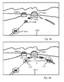
- FIG. 4 b shows another forward view from the camera mounted inside host vehicle illustrating another embodiment of headway computation, according to an embodiment of the present invention.
- FIG. 4 c illustrates a method for determining headway, according to an embodiment of the present invention without having or requiring speed of host vehicle.
- FIG. 4 d illustrates another method for determining headway, according to an embodiment of the present invention without having or requiring speed of host vehicle.
- FIG. 5 a which illustrates schematically a rear view camera system mounted on host vehicle, according to an aspect of the present invention.
- FIG. 7 a shows a conventional design of an adjustable camera mount.
- FIGS. 7 b and 7 c show an embodiment of a camera mount according to the present invention.
- FIG. 7 h is a flow chart illustrating a method for mounting the camera behind the windshield according to an embodiment of the present invention.
- FIG. 7 i illustrates a camera mount according to another embodiment of the present invention.
- FIG. 1 a illustrates a vehicle 108 in which a camera 104 is mounted typically just inside the windshield near the centerline of vehicle 108 and close to the rear-view mirror attachment.
- a camera mount 70 according to embodiments of the present invention facilitates mounting camera 70 in close proximity to the windshield.
- camera 104 is attached to a processor 100 to provide a hardware platform 10 suitable for bundling driving assistance applications according to embodiments of the present invention.
- Camera 104 includes optics, e.g. lens 105 and an image sensor 106 .
- spatial color filter 30 is located in the focal plane of lens 105 .
- Image frames 102 are shown schematically which are transferred from image sensor 106 to processor 100 for simultaneously performing different driver assistance functions, according to embodiments of the present invention.
- Processor 100 is configured to operate according to a number of algorithms. After mounting, camera 104 , a calibration procedure 62 is used to calibrate angular orientation, i.e. pitch, yaw and roll of camera 104 , and to find camera height.
- a target 60 used for the calibration (process 62 ) of camera 104 is shown in FIG. 1 a , according to embodiments of the present invention.
- Other processes for which processor 100 is configured, according to embodiments of the present invention are: traffic sign detection 20 ; electronic traffic sign recognition 22 , fog detection 50 , and a method 40 for determining headway 40 .
- Image frames are partitioned into three slots or partitions so that three image frames (frame 1, frame 2 and frame 3) are captured in sequence with different image capture parameters (e.g gain, exposure time). A complete set of three frames is captured typically in 66 milliseconds.
- Image frame 1 which has a relatively long exposure is primarily used for lane departure warning (LDW) and vehicle detection. Clear lane marks are detected even in low light conditions. However, the relatively long exposure produces motion blur on traffic signs which makes traffic signs unreadable or unrecognizable. Furthermore, distant oncoming lights tend to have blurred image spots.
- LDW lane departure warning
- the outline of a vehicle ahead and the vehicle point of contact with the ground may also be determined using image frame 1, which may then be used to compute distance and time-to-contact according to U.S.
- FCW forward collision warning
- AHC automatic high beam control
- TSR traffic sign recognition
- the maximum allowable exposure combined with the maximum gain give an image which is too bright and the traffic sign is saturated.
- brightness of the sign is predicted based on the distance (derived from the image size of the circle), the angle based on the predicted location of the sign in the image and/or the high/low beam status.
- the gain and exposure are then set accordingly. Further adjustment can be made using closed loop control. Since the image frame 2 uses a high gain, it has significant image noise and not optimal for LDW under low light and/or poorly contrasted lane markings. However image frame 2 does give useful information on well-marked highways and can effectively double the frame rate on such roads which are more typical for fast moving vehicles.
- Image frame 3 has a short exposure and may be used together with longer exposure image frame 1 for accurate interpretation of light sources. For example, oncoming headlights of one or more vehicles in image frame 1 appear as a bright cluster of lights. Short exposure image frame 3 of the bright cluster can clearly distinguish the cluster as the oncoming headlights.
- FIG. 2 a illustrates a method for detection of and subsequent recognition of non-electronic traffic signs, according to an embodiment of the present invention.
- Image frames from camera 104 are partitioned (step 200 ) into multiple portions or partitions. Long exposure times are set (step 202 ) for the first partition and shorter exposure times are set (step 206 ) for the second partition.
- Image frames 102 are captured, typically alternating between image frames 102 of the first partition and of the second partition.
- Image frames 102 are transferred (step 212 ) to processor 100 .
- Detection of traffic signs is performed (step 213 ) using the first partition with the longer exposure times and recognition (step 214 ) of the traffic sign is performed using the second partition of image frames with shorter exposure.
- setting exposure times or gains for first partition of image frames 102 is achieved using a gain control, and exposure times (or gains) are set in step 206 for the second partition based on the controlled parameter of the first partition.
- the light emitting diodes (LEDs) of pulsed electronic traffic signs are not on all the time but are pulsed on and off at a frequency of typically 80-160 cycles/sec Hertz (Hz.).
- the frame exposure time may be selected so as not to oversaturate the image of the electronic traffic sign but still capture the full cycles of the switching light emitting diodes (LED).
- LED frequency, duty cycle and intensity vary from sign to sign.
- the operating parameters of pulsed electronic traffic signs may vary from country to country and even may vary according to the time of day and ambient light levels. However the cycle time of most or all LED signs is longer than about 6 milliseconds and less than about 11.4 milliseconds.
- FIG. 2 b illustrates image sensor 106 , according to a feature of the present invention.
- Camera 104 is previously aligned in vehicle 108 so that image regions (A, B and C) of image sensor 106 are imaged in image frames 102 .
- Region C includes an image of the road region (immediately in front of vehicle 108 ), regions A and B image the sides of the road region where electronic signs are possibly located.
- Image sensor 106 has two main parameters that affect the image brightness: exposure (also known as integration time) and gain.
- FIG. 2 c illustrates a feature of the present invention, a method of setting camera parameters in a second partition of image frames, e.g. image frames 2 based on a first partition, image frames 1 for example using the AGC of image frames 1.
- the exposure/gain control of camera 104 has different algorithms (executed by processor 100 ) and settings for day, dusk and night operation.
- decision box 220 the decision of processor 100 between day, dusk and night modes of image frames 2 is optionally based on the exposure/gain parameters of another image frame, typically image frame 1 or time-to-lane crossing (TLC) frame used in LDW.
- a classic automatic-gain-control (AGC) algorithm may be used for image frame 1 so that a certain percentage of pixels in a specified image region (e.g. A, B and/or C) are within a certain value range.
- time-to-lane crossing (TLC) image frame 1 the gain and exposure is set so that 93% of the pixels in the regions A, B and C are below a value of 144 (out of 155).
- Image frame 1 automatic gain control is designed to keep the gain as low as possible and exposure is increased first to a maximum of about 40 milliseconds.
- processor 100 specifies ‘dusk’ mode for image frame 2 and when the exposure passes 30 milliseconds processor 100 specifies ‘night’ mode.
- the automatic high beam control (AHC) algorithm is not active and image frame 3 allocated (at night) for the automatic high beam control (AHC) algorithm may be used by the traffic sign detection and recognition algorithm in the day.
- the traffic sign detection and recognition algorithm typically controls the exposure and gain settings of image frame 3.
- image frame 1 may also be used by traffic sign detection and recognition algorithm but the exposure and gain are optimized for lane departure warning.
- the brightness of the road surface is generally a much better indicator of the general illumination.
- the gain control algorithm for traffic sign detection (step 221 ) candidate search is similar to the AGC (step 220 ) used for the LDW frame (image frame 1) but with different parameters even though they both use road region C. Exposure settings are selected so that 93% of the pixels are below 128 (out of 256). The above setting works well in most cases. However if the road surface appears washed out due to low sun in front, the algorithm parameters are adjusted and the exposure is set so that 30% of the pixels are below a value of 111.
- the AGC used is for both electronic and non-electronic traffic signs. After detection different strategies are used for the electronic and non-electronic traffic signs.
- a circle candidate is detected (decision box 222 ) the system is switched to a closed loop AGC.
- Electronic signs are typically bright. To test for an electronic sign in the daytime, we first require that a certain percent of pixels are above a certain threshold (e.g. in saturation). For example we require that 25% of the pixels inside the candidate circle are in saturation. If the candidate passes this first test we run an SVM classifier trained on candidates that were electronic signs and candidates that were regular signs as a negative training set or ‘falses’.
- image frame 1 LDW
- TSR image frame 2
- AHC image frame 3
- the TSR frame gain and exposure is set as for day closed loop AGC.
- Image frame 1 (LDW) frame uses the settings optimized for LDW.
- Image frame 3 is set to an exposure of 1.5 milliseconds unless either the LDW or TSR frames are set to exposure of anything between 1.2 milliseconds and 1.8 milliseconds. In that case, the image frame 3 (AHC) is set to 3 milliseconds.
- the automatic high beam control (AHC) algorithm In ‘Night Mode’ the automatic high beam control (AHC) algorithm is active and the gain and exposure settings for the automatic high beam control (AHC) image frame 3 are set by the automatic high beam control (AHC) algorithm. These are optionally a fixed cycle of four exposure settings ⁇ 6 ms 0.75 ms 3.9 ms 0.75 ms ⁇ . The gain is set to 1.
- the automatic high beam control (AHC) image frame 3 may also be used by the traffic sign recognition (TSR) algorithm.
- TSR traffic sign recognition
- image frame 2 is running at a fixed exposure of 13.5 milliseconds and gain of 4.
- the respective locations in image space in current traffic sign recognition (TSR) frame 2 and previous traffic sign recognition (TSR) frame 2 may be used to interpolate and get a position in automatic high beam control (AHC) frame 3.
- a classifier SVM
- SVM classifier
- AHC automatic high beam control
- a classifier SVM
- a classifier A classifier
- AGC closed loop automatic gain control
- the traffic sign recognition (TSR) frame settings are now optimized for recognition of non-electronic signs.
- the gain and exposure settings used for the traffic sign recognition (TSR) frame (image frame 2) are determined dynamically. Once the outline circle of a traffic sign has been detected and tracked in two images (any combination of long exposure frames and traffic sign recognition (TSR) frames) it is possible to predict the location and size of the sign in the next image frame. It is also possible to determine the maximum allowable exposure that will keep the motion blur below a certain limit. Motion blur is typically kept to less than one pixel.
- the maximum allowable exposure combined with the maximum gain give an image which is too bright and the traffic sign is saturated.
- the brightness of the sign is predicted based on the distance (derived from the image size of the circle), the angle based on the predicted location of sign in the image and the high/low beam status.
- the gain and exposure are then set accordingly. This can typically be done for OEM serial production where the type of headlights and windshield glass is known.
- gain and/or exposure are adjusted to a lower setting. For example, for exposure time 9 milliseconds and gain 3 gives half of the brightness of the standard exposure of 13.5 milliseconds and gain 4.
- the automatic high beam control (AHC) frame is typically also used for non-electronic traffic sign recognition and a traffic sign recognition classifier is run on all image frames 1, 2 and 3.
- Electronic signs are quite bright and the brightness of their images is not affected by the cone of illumination of the vehicle headlights.
- the full LED cycle is captured and an image is required which is not over saturated.
- LED frequency, duty cycle and intensity vary from sign to sign.
- the cycle time of all LEDs is smaller than 11.4 milliseconds and longer than 6 milliseconds. However an exposure of 11.4 milliseconds, even with minimal gain, sometimes leads to saturation. If the exposure time for all image frames is uniformly decreased to 4.5 milliseconds or less there may be frames where the sign is not captured.
- Some back illuminated signs are not LEDs and require very short exposure (0.75 milliseconds). If the AGC is in the night Electronic sign mode there is an appropriate exposure frame every triplet. However, back illuminated signs are often not classified as electronic signs and the AGC is in night non-electronic sign mode. In this case, it is the short automatic high beam control (AHC) image frames 3 that give the correct classification.
- AHC short automatic high beam control
- the TSR frame (image frame 2) settings are adjusted using the AGC day algorithm. This is a typical scenario where we will have to deal with low light from in front.
- Both the TSR (image frame 2) and AHC (image frame 3) frames are used for classification.
- a sensor appropriate for embodiments of the present invention is a wide VGA sensor with resolution 752 ⁇ 480.
- Sensor 106 has a 6 ⁇ m ⁇ 6 ⁇ m square pixel. It has a global shutter and can switch exposure and gain settings every frame.
- One unusual aspect of camera is that it includes focal plane filter 30 with only red and clear pixels. The red pixels are arranged as they would be on a standard Bayer pattern but the green and blue filters are missing. This is done in order to combine most of the advantages of the monochrome sensor in terms of low light sensitivity and sensor 106 resolution with some color information; in particular, the ability to distinguish between red and white lights.
- the lens example discussed is a 5.7 mm lens with a low F number F1.6 5.7 mm (e.g. Marshall Electronics Inc., El Segundo, Calif.).
- An infra-red (IR) cutoff lens filter may be used to give a consistent response with a variety of windshields whose transmittance characteristics in the IR spectrum can vary widely.
- the lens filter selected is an IR cutoff filter with the 50% cutoff set at 700 nm rather than the typical 650 nm. This lens filter lets in more light and increases the low light performance in detection of lanes and traffic signs under halogen headlights in particular and also increases the detection range for red taillights.
- the sensor 106 /lens 105 configuration in camera 104 gives a field of view of 0.06° per pixel or 45° ⁇ 29° over whole sensor 106 .
- F lens focal length
- red/clear filter focal plane filter 30 works well, there are applications that could benefit from the full 3-dimensional color space. For example to determine traffic light colors—green, yellow and red, or to expand the range of traffic signs that can be detected; for example, to differentiate between yellow (recommended) and white (obligatory) speed signs in North America. Color information could also be used for classifying lane marking types (white, yellow, orange and blue are typical some examples). In fact, without color information, some lane mark color and road surface configurations make the lane marks invisible or with very low contrast when imaged in monochrome. These can be enhanced using a particular color filter over the whole image but the choice of filter would be region specific.
- Newer xenon or high intensity discharge (HID) lamps have a stronger blue component so there is noticeable drop in sensor response with the added yellow filter.
- these headlights are so much brighter in general than the older halogen headlights that even with the yellow filter the response is strong enough.
- an RGB sensor can be used for LDW and TSR.
- the new LED technology also falls into this second category.
- NIR near infrared
- Typical automotive windshield glass has a NIR cutoff characteristic however it usually only reduces near infrared transmittance to 30%. Newer and more expensive glass filters the NIR transmittance down to 10%, however this glass is usually on high end vehicle where HID headlights are used and scene brightness is not an issue.
- the yellow filter has the added advantage that it enhances the contrast, in daytime, between yellow lane markings and the concrete road surface often used in the USA. Understanding that yellow is the best color filter to use for low light situations, leads to the idea of using a CYM (Cyan, Yellow and Magenta) instead of the standard RGB.
- 3 c and 3 d which schematically show two examples of the color pattern of CYM focal plane filter 30 , according to embodiments of the present invention.
- the yellow portion (Y) replaces the green in the standard Bayer pattern so the yellow portion has the maximum resolution using half of the pixels.
- the remaining pixels alternate between magenta (M) and cyan (Y).
- M magenta
- Y cyan
- a standard CYM filter is preferably modified, according to an exemplary embodiment of the present invention.
- the cyan filter as used in standard CYM filters is preferably modified so that it blocks out or significantly reduces the NIR from 750 nanometers to at least 800 nanometers.
- a graph of responsivity with a modified cyan filter, according to a feature of the present invention is shown in FIG. 3 b .
- the Mobileye AWS 4000 system uses a monochrome sensor.
- the algorithm uses, among other algorithms, various classifiers which were trained using hundreds of thousands of training samples. Accumulating such a large database of much time and effort. In order to avoid having such an effort going to waste when switching to the CYM sensor the same examples are reused.
- the images captured from a monochrome camera or from a monochrome camera with a yellow filter are very similar. The differences are negligible.
- the response of the cyan and magenta pixels will be different from the yellow pixel response creating spurious edges. Given that the color of the viewed object is not known the cyan and magenta values cannot be adjusted automatically to give the correct yellow response.
- the solution is to use only the yellow pixels as input to the classifier.
- the values at the cyan and magenta pixel locations are interpolated based on the yellow neighboring pixels. These images will still appear different from the images obtained from the monochrome sensor however they can correctly be simulated from the monochrome data.
- As a training set for the classifiers using the CYM sensor we use the monochrome images where we interpolate in a checker board fashion. We use the ‘white’ pixels as is and interpolate the ‘black’ to get one example image and then use the ‘black’ to interpolate the ‘white’ to get a second example image.
- FIG. 4 a shows a forward view 402 a from camera 104 mounted inside host vehicle 108 ( FIG. 1 a ) according to an embodiment of the present invention.
- Camera 104 is preferably a monocular camera mounted close to the rear mirror, looking forward out through the windshield of host vehicle 108 .
- Forward view 402 a shows two vehicles 408 L and 408 R in two lanes and the progression of a feature 404 a - 404 n (behind vehicles 408 ) in the road surface for successively captured image frames 102 .
- Examples of features 404 a - 404 n in the road are typically the end of a lane mark segment, shadows or tar seams.
- One method to determine headway is to estimate the distance of vehicle 408 R ahead and then divide by the speed of host vehicle 108 . This will give the time it takes host vehicle 108 to reach the current position of vehicle 408 R.
- Method 40 a is implemented by an algorithm in processor 100 which determines the time for host vehicle 108 to reach the current position of preceding vehicle 408 R.
- Method 40 a locates (step 420 ) a feature point 404 a on the road surface that is on the same horizontal image line as the bottom of preceding vehicle 408 R. At this point in time, feature point 404 a on the road and the preceding vehicle 408 R are at the same distance from host vehicle 108 .
- Feature point 404 a is then tracked (step 422 ) in the next few frames (the same feature point now labeled 404 b in FIG. 4 a ) till the bottom of the image frame 102 is reached i.e. feature point 404 n .
- the time stamp of the first image frame 102 showing feature point 404 a is then subtracted (step 424 ) from the time stamp of the image frame 102 where the feature point 404 n has reached the bottom of image frame 102 .
- the subtraction (step 424 ) between the time stamp of the first image frame 102 and the time stamp of the image frame 102 where the feature point 404 n has reached the bottom of image frame 102 gives an estimate (step 426 ) of the headway in seconds.
- SIFT scale invariant feature transform
- FIG. 4 b shows another forward view 402 b from camera 104 mounted inside a host vehicle 108 according to another embodiment of the present invention.
- Forward view 402 b shows two vehicles 408 L and 408 R in two lanes and the progression of two pairs of features 410 and 412 (behind vehicle 408 R) in the road surface for successively captured image frames 102 .
- a substantially horizontal distance d 1 separates features 410 and 412 and a substantially horizontal distance d 2 separates features 410 and 412 in successively captured image frames 102 .
- Examples of features 410 and 412 in the road are typically the end of a lane mark segment, shadows or tar seams.
- both features 410 and 412 are tracked (step 432 ) in every captured image frame 102 .
- image distance for example d 1
- T ttc time-to-contact
- FCW forward collision warning
- both feature points 410 and 412 are tracked (step 432 ) in the next few image frames 102 until the change in distance between successively tracked feature points 410 and 412 is significant (for example if the size of feature points 410 and 412 doubles).
- Image frame 102 that produces the situation where the distance between successively tracked feature points 410 and 412 is significant is known as a second image frame.
- the time stamp of the first image frame is subtracted (step 434 ) from the time stamp of the second image frame.
- the subtraction between the time stamp of the first image frame and the time stamp of the second image frame is known as the time difference ( ⁇ T).
- the time to contact (T ttc ) is then computed (step 436 ) using:
- T ttc d 1 ⁇ ⁇ ⁇ ⁇ T d 1 - d 2
- T ttc or headway is then given by the time difference found for example from the difference between the time stamps of the image frames divided by the relative change of distance
- time to contact (T ttc ) can be improved further by using measurements from multiple or all the image frames 102 ( i ).
- a plot of 1/d i as a function of ⁇ T i for each value of time (T) may be made.
- the points of the plot can be fit with a linear fit producing a line and the point of intersection of the line with the time (T) axis will give the time to contact (T ttc ) or headway distance.
- the line can also be fit to a parabola to account for acceleration of host vehicle 108 .
- the headway computed using distance/speed may be combined with the headway computed using method 40 a and/or 40 b to give a more robust warning signal.
- V speed
- T ttc time to contact
- Fog detection is an important feature when driving at night since, in the presence of fog, a different light strategy is used.
- the driver switches off high beams and switches on fog lamps if available.
- the light strategy during fog is used because light scattered from the high beams in the presence of fog may blind the driver. Not all drivers are aware of this however, and often respond incorrectly to the reduced visibility due to the fog by switching on their high beams. By so doing, they reduce the visibility even more.
- a fog detection system which can advise the driver or switch lights on and off automatically would be useful.
- One method uses spatial gradients in the image. During heavy fog the image contrast drops and so the image loses its sharper edges.
- a more direct measure of the driver's need to lower high beams is the amount of scatter produced by the atmospheric conditions. If the scene is dark then it is possible to detect the light of the host vehicle high-beams scattered by the fog back to the camera.
- the high beams have a very particular back scatter pattern which is determined by the location of the forward looking camera and the vehicle headlights.
- the back scatter pattern from the high beams of the host vehicle may be learned by using machine learning techniques.
- the input feature vector may be a few horizontal lines from a low resolution image.
- the problem is that low beams do not give rise to strong scatter pattern. This is due to the fact that the low beams illuminate the close road which also reflects back to the camera. There is not a significant difference in the reflection pattern from the road or the scatter pattern from the low beams. This means that it is hard to give the driver, who has switched to low beams due to the fog, an indication that the fog has ended and now is a good time to switch back to high beam.
- This method may be less applicable in an illuminated night scene.
- an average driver would use low beams. Fog is readily detectable when other light sources such as street lights are in the scene or other cars with their lights on (high or low) are viewed from the side.
- FIG. 5 a illustrates schematically a rear view camera system 50 mounted on host vehicle 108 , according to an aspect of the present invention
- Rear camera 104 R is shown mounted on the rear of vehicle 108 , typically centered along the rear of vehicle 108 and oriented backward.
- One use of rear camera system 50 is for detection of obstructions behind vehicle 108 .
- Obstruction detection using rear camera system 50 is disclosed in co-pending US patent application publication 20080266396 and international application PCT/US/08062003.
- the horizontal field of view (HFOV) of camera 104 R is large between 130 and 180 degrees.
- Rear-view camera may view almost the entire cone of light emanating from the host vehicle taillights 107 .
- HFOV horizontal field of view
- the cone of light from taillights 107 is shown schematically as between two dotted lines.
- rear camera 104 R is well located to observe light scatter from taillights 107 due to fog 51 shown as a droplet of water.
- An incident light ray i is shown and a scattered light ray s scattered into the aperture of camera 104 R.
- the light emitted from the taillights is red.
- the detected scattered light will have a red hue which differentiates the detected scattered light from white background light.
- FIG. 5 b illustrates schematically by way of flow chart a simplified method 52 for detecting fog 51 using camera 104 R or camera 104 , according to an embodiment of the present invention.
- a large number of image frames 501 are used for training (step 503 ) in order to produce a trained classifier 505 .
- Trained classifier 505 is subsequently used to classify (step 509 ) a detected halo as fog when the halo is detected (step 507 )
- the image is reduced to 160 ⁇ 120 red/green/blue RGB pixels (i.e. the red, green and blue pixels are averaged separately to preserve color information) and optionally only the left and right 30 columns of the top half of the image are used for fog detection.
- the result is a feature vector of 80*(2*30) ⁇ 3 values.
- any change in rear light status such as braking, reverse or even turn signals. Any change in brightness that corresponds in time to changes in rear light status may give further indication as to scattering.
- FIG. 5 c illustrates a method 53 , according to another embodiment of the present invention.
- Certain LED taillights flicker at a high frequency.
- video capture By synchronizing (process 54 ) video capture to the switching frequency of taillights 107 one can sequentially capture images (steps 523 ) with taillight illumination and capture images (step 527 ) without taillight illumination. It would also be possible for the system to initiate a brief flickering of the taillights even in the case of regular incandescent taillights to achieve a similar effect.
- Taillights or other illumination may be switched on (step 521 ) and very briefly switched off (step 525 ).
- Subtracting (step 529 )) or otherwise comparing or correlating the two or more captured images) may include a subtracted image of the light scattered with an enhanced the signal to background ratio for use in fog detection (step 531 ) based on light scatter in the subtracted image.
- a special light source such as a LED with a focused beam may be mounted on the car hood in front of the camera with the beam facing up. Since it is a dedicated light source it can be alternatively switched on and off synchronously with image frames of either camera 104 or 104 R and then image subtracted the light scattered from the dedicated light source may be sensed.
- a first image is captured (step 603 ) of target 60 .
- Target 60 is relocated (step 605 ) to a second distance, e.g. moved back away from vehicle 108 approximately one meter. The lateral location of the target in the second position is not important.
- a second image is captured (step 607 ) of target 60 .
- a mapping (step 609 ) is performed between respective image coordinates of the first image and the second image.
- a stationary point during mapping (step 609 ) is a focus of expansion (FOE) typically on the horizon. This provides the Y coordinate of the FOE used in the algorithms.
- the lateral position of the target in the first image provides the X coordinate of the FOE used in the algorithms. If the camera is not located in the center of the image this is adjusted for. and adjusted to correspond to the center of vehicle 108 .
- Method 62 may provide the camera orientation in all three angles and the camera height.
- Target 60 includes an optical pattern 615 b mounted for instance on a rigid upright pole 610 .
- the base 613 is preferably sufficiently heavy so that it does not wobble. It is recommended that base 613 have three points of support to insure stability.
- Pattern 615 optionally includes a narrow checker pattern, an example of which is shown in FIG. 6 b and enlarged in FIG. 6 d . In this case the squares are optionally five centimeters on the edge.
- Another example of pattern 615 is shown in FIG. 6 e .
- the narrow shape is tends to keep target 60 more stable and to reduce the chance of being blown over by wind.
- the height of target 60 is designed to be wholly visible when placed close to the bumper of vehicle 108 . A different target height is typically required for trucks and automobiles.
- FIG. 6 d illustrates pattern 615 b with six rows of alternating black and white squares.
- Five saddle points 617 are shown marked with small circles with dotted lines while only the topmost saddle point is labeled with the reference number 617 so as not to clutter the drawing.
- With an additional five centimeters of wide margin above and below the total target is 40 centimeters high. However, only the middle 30 cm may be visible in the image of camera 104 .
- L 30 centimeter target length (six rows of five centimeters in FIG. 6 d )
- the distance between uppermost and lowermost saddle points is 80 pixels which is typically adequate for roll computation even if target 60 is 1.7 m away.
- Camera 104 has been assumed to be horizontal. Consider that camera 104 is pointed down 20-70 pixels. Taking the 5 middle pixel (i.e. 45 pixels) at 1.5 meters, 45 pixels in image space translates in real space to:
- Pattern 615 c shown in FIG. 6 c may be used for camera heights ranging from 120 cm to about 200 cm. corresponding to both smaller automobiles and trucks.
- FIG. 6 f illustrates pattern 615 c in more detail.
- a center portion of 6 rows such as that marked with reference 618 of pattern 615 c is optionally used for performing method 62 .
- Two additional strips 619 allow for unique identification of saddle points 617 .
- Pattern 615 c includes an innovative feature so each set of six saddle points has a unique code based on strips 619 . With nine saddle points 617 , at least one transition in strips 619 is imaged and vertical position within pattern 615 c may be determined. Note that the corners of strips 619 align with the corners of the black squares to avoid additional saddle points which may be confused with saddle points 617 . Pattern 615 c is preferably limited in height to about 1 meter so that it does not become to long for packing.
- Pattern 615 c is also optimally of length similar to the longest element of stand 610 so that pattern 615 c fits in the same package for shipment. Alternatively, the length of pattern 615 c may be extended to 1.6 meters or 1.8 meters without adding another vertical stripe for coding saddle point 617 positions.
- pattern 615 may be inverted around a rotation point 616 high up on pattern 616 .
- Markings 619 in pattern 615 c are designed to be unique under target rotation.
- D be the image distance between saddle points 617 .
- D the image distance between saddle points 617 .
- For each saddle point 617 we look at the regions 0.5 D to above and 1.5 D to the left and right and check if that region is white or black:
- the method first detects saddle points where two black squares meet. These are then matched between the two target images. The vertical positions of the points in the two images are used to estimate the stationary point of the horizon, focus of expansion (FOE) Y or horizon. The lateral position of the close target is used to estimate the lateral position of the calibration, focus of expansion (X) or Yaw.
- the average X position of the point can be used as is.
- the lateral position of the points in the far pole position is ignored since target pole 50 b is not centered on vehicle 108 . If camera 104 is mounted with an offset to the center this is preferably accounted for.
- Saddle points are known to be the local minimum of the determinant of the Hessian.
- the first step is to find these local minima with a small threshold. Note, this measure is orientation invariant. This can be computed on a 320 by 240 image.
- the second step is to verify these points using normalized cross correlation with a template of a simple checker pattern with two black and two white squares.
- the size of each square is kept small: typically 5 pixels for the side. Only points with a high enough (positive or negative) score are kept.
- the results for the close image are shown in by blue points in the bottom left image. Note one spurious point on the dark vehicle parked on the right.
- the determinant of the Hessian is:
- dx [ - 0.25 0 0.25 - 0.5 0 0.5 - 0.25 0 0.25 ]
- ⁇ dy [ 0.25 0.5 0.25 0 0 0 - 0.25 - 0.5 - 0.25 ]
- Points are verified to be saddle points if their normalized 2D correlation with a saddle shaped template is greater than 0.7 (or smaller than ⁇ 0.7).
- the correlation function is based on Matlab corr2.m.
- the template is a 22 checker board pattern with squares of size 6 pixels. It is intentionally orientation dependent.
- the lateral position of the FOE (or ‘yaw’) is given by the lateral position of the close target.
- C x in the camera lateral offset in cm and T pixels , B pixels , T cm and B cm are in the position of the top and bottom saddle points in the image and in centimeters from the ground respectively.
- To compute camera height we convert the coordinates of the stationary point y o (also known as FOE y or horizon) to height from the floor.
- the camera roll is computed from the close target:
- Xr, XB, Yr and YB are the x and y coordinates of the top and bottom saddle points respectively.
- An alternative solution is to use an adjustable mount that can accommodate a variety of angles and is adjusted after fixing the mount to the glass so as to bring the camera to the desired angle. While the angle of camera 104 is correct, the position of camera 104 relative to the glass is not optimal and the distance can be quite large, especially for sharp rake angles. This in turn significantly increases the size of the light shield often attached around camera 104 ; the light shield is recommended for eliminating stray light reflecting into the camera aperture from the windshield glass.
- Various mount designs are presented, according to different embodiments of the present invention which allow both adjustment of the angle and ensuring that lens 105 is optimally close to glass 701 .
- FIG. 7 a shows a conventional design of an adjustable mount.
- a camera 104 moves away from the glass.
- the same problem occurs if a ball socket is used with the ball centered above or ball camera 104 or if camera 104 fits inside a sphere mounted inside a ball socket of the same diameter so that camera 104 may be adjusted in all three angles.
- extension 705 is in line with upper edge of lens 105 .
- axis pin 703 is attached which is parallel to the glass plane.
- Axis pins 703 fit into corresponding holes in extension 705 . If we wish to have lens 105 actually touch the glass, the holes in the mount extensions 705 may be replaced by grooves and the glass itself closes onto pin 703 .
- camera 104 is locked into position optionally by applying an adhesive, e.g. epoxy adhesive, between extension 705 and fixed element 707 .
- an adhesive e.g. epoxy adhesive
- FIG. 7 d shows a modification of the previous design ( FIGS. 7 a -7 c ) in which an arm 709 with a slot is attached to each side of fixed element 707 and camera body 104 . (only one side is shown) Arm 709 rotates around a point 711 on fixed element 707 and slides along pins 713 protruding from camera body 104 . If pins 713 are threaded, a nut or wing nut may be used to lock the camera angle.
- FIG. 7 i illustrating camera mount 70 according to another embodiment of the present invention.
- Arm 709 may have another hole, one for the pin at point 711 connecting to fixed element 707 and the other for a pin 716 attached to camera body 104 .
- the axis at point 703 at the tip of lens 105 may slide in a slot along the glass of windshield 701 . If the pin at point 703 is not actually at the tip of lens 105 but further back, a curved slot may be designed that constrains the tip of lens 105 to move along a straight path while touching the glass.
- FIG. 7 e illustrates two views of a second embodiment of the present invention.
- the two views differ by the angles of windshield 701 .
- the opposite corner 704 of camera body 104 marks a circular path whose center is point 703 of contact between lens 105 and glass 701 . Since opposite corner 704 is the most distant point on camera 104 from the tip of lens 105 , the semi-circle shown encloses all of camera 104 during adjustment.
- FIGS. 7 f and 7 g show a side view and rear view respectively, of camera mount 70 , according to an embodiment of the present invention.
- Camera body 104 may be modified so that instead of a sharp corner at point 704 it has a flat or beveled surface 704 at the point of contact with a semi-circular strip 714 .
- the flat surface at point 704 is perpendicular to a radius of semi-circular element 714 .
- One way to pull the flat camera surface tightly towards the semi-circular mount 714 is with a fastener 717 , e.g. wing nut or screw.
- a slot e.g. of two centimeters, in width is bent into a semi-circle and a slot 715 is cut into it.
- a threaded hole may be tapped through flat surface on camera body 104 .
- Screw 717 is optionally inserted through slot 715 and then screwed into camera body 104 . When screw 717 is tightened the flat surface is pulled tightly towards semi-circular element 714 .
- Another option is to glue the flat surface to semicircular element 714 once the correct angle has been determined.
- Another option is to have the semicircle ferromagnetic and camera body 104 be a magnet. Camera 104 is typically constrained to have only one degree of freedom in movement since the flat surface is a rectangular shaped and the minimum distance (radius) is achieved when opposite edges of the rectangle touch semi-circular element 714 . If however, camera body 104 is part of a sphere, then the surface at point 704 is a circle. Semi-circular element 714 may be formed from a hemisphere. Screw 717 may then give a second axis of rotation and allow for an adjustment of camera roll. Some lateral rotation (pan) motion is also possible.
- Semi-circular element 714 may be a portion of a sphere and camera body 104 may be a portion of sphere of the same diameter, so that tip 703 of lens 105 is the center of the sphere.
- the screw hole may be placed on any location on camera body 104 .
- the screw hole may be placed on the optical axis of camera 104 enabling two axis of motion. Vertical motion to account for windshield rake angle and rotation around the optical axis to account for roll. If camera body 104 is attached to mount 714 using glue or a magnet then the hemisphere inside hemisphere design gives also a lateral rotation (pan) by relaxing the requirement that tip 703 of lens 105 touches glass 701
- FIG. 7 h illustrating a method for mounting a camera behind a windshield according to an embodiment of the present invention.
- a tilt rotation axis is provided (step 750 ) at a point between the lens mount and the windshield.
- the front tip of the lens mount is constrained (step 752 ) to be in close proximity to or to contact the inside of the windshield for different rake angles of the windshield.
Abstract
Description
R=n 1 ā 1 +n 2 ā 2
where ni are any integers and āi are known as the primitive vectors which lie in a plane and span the lattice. For any choice of position vector, the lattice looks the same.
-
- Scene is sort of lit (day like). The AHC function is not active and the AHC frame
slot image frame 3 may be controlled by the traffic sign recognition algorithm. - Cars are switching on lights
- LED duty cycle changes.
- Scene is sort of lit (day like). The AHC function is not active and the AHC frame
is known herein as the relative change of distance in image space. The time-to-contact Tttc or headway is then given by the time difference found for example from the difference between the time stamps of the image frames divided by the relative change of distance
Z=V×T ttc
C=2·L+R
X offset=7/5·10=14 pixels
Locating the Target Points in Each Image
-
- i. Sort points in y
- ii. Starting from top point
- iii. Check if N points it matches sequence of left right template. If yes, then mark points as used and return points as line.
- iv. Go to next unused point.
y 2 =S(y 1 −y 0)+y 0
Computing Camera Roll
Claims (12)
Priority Applications (3)
| Application Number | Priority Date | Filing Date | Title |
|---|---|---|---|
| US13/484,684 US9459515B2 (en) | 2008-12-05 | 2012-05-31 | Adjustable camera mount for a vehicle windshield |
| US15/245,738 US10139708B2 (en) | 2008-12-05 | 2016-08-24 | Adjustable camera mount for a vehicle windshield |
| US16/176,518 US11029583B2 (en) | 2008-12-05 | 2018-10-31 | Adjustable camera mount for a vehicle windshield |
Applications Claiming Priority (3)
| Application Number | Priority Date | Filing Date | Title |
|---|---|---|---|
| US19352808P | 2008-12-05 | 2008-12-05 | |
| US12/573,836 US8254635B2 (en) | 2007-12-06 | 2009-10-05 | Bundling of driver assistance systems |
| US13/484,684 US9459515B2 (en) | 2008-12-05 | 2012-05-31 | Adjustable camera mount for a vehicle windshield |
Related Parent Applications (1)
| Application Number | Title | Priority Date | Filing Date |
|---|---|---|---|
| US12/573,836 Continuation US8254635B2 (en) | 2007-12-06 | 2009-10-05 | Bundling of driver assistance systems |
Related Child Applications (1)
| Application Number | Title | Priority Date | Filing Date |
|---|---|---|---|
| US15/245,738 Continuation US10139708B2 (en) | 2008-12-05 | 2016-08-24 | Adjustable camera mount for a vehicle windshield |
Publications (2)
| Publication Number | Publication Date |
|---|---|
| US20120233841A1 US20120233841A1 (en) | 2012-09-20 |
| US9459515B2 true US9459515B2 (en) | 2016-10-04 |
Family
ID=46827284
Family Applications (3)
| Application Number | Title | Priority Date | Filing Date |
|---|---|---|---|
| US13/484,684 Active US9459515B2 (en) | 2008-12-05 | 2012-05-31 | Adjustable camera mount for a vehicle windshield |
| US15/245,738 Active US10139708B2 (en) | 2008-12-05 | 2016-08-24 | Adjustable camera mount for a vehicle windshield |
| US16/176,518 Active US11029583B2 (en) | 2008-12-05 | 2018-10-31 | Adjustable camera mount for a vehicle windshield |
Family Applications After (2)
| Application Number | Title | Priority Date | Filing Date |
|---|---|---|---|
| US15/245,738 Active US10139708B2 (en) | 2008-12-05 | 2016-08-24 | Adjustable camera mount for a vehicle windshield |
| US16/176,518 Active US11029583B2 (en) | 2008-12-05 | 2018-10-31 | Adjustable camera mount for a vehicle windshield |
Country Status (1)
| Country | Link |
|---|---|
| US (3) | US9459515B2 (en) |
Cited By (69)
| Publication number | Priority date | Publication date | Assignee | Title |
|---|---|---|---|---|
| US9952594B1 (en) | 2017-04-07 | 2018-04-24 | TuSimple | System and method for traffic data collection using unmanned aerial vehicles (UAVs) |
| US9953236B1 (en) | 2017-03-10 | 2018-04-24 | TuSimple | System and method for semantic segmentation using dense upsampling convolution (DUC) |
| US10007854B2 (en) * | 2016-07-07 | 2018-06-26 | Ants Technology (Hk) Limited | Computer vision based driver assistance devices, systems, methods and associated computer executable code |
| US10067509B1 (en) | 2017-03-10 | 2018-09-04 | TuSimple | System and method for occluding contour detection |
| US10147193B2 (en) | 2017-03-10 | 2018-12-04 | TuSimple | System and method for semantic segmentation using hybrid dilated convolution (HDC) |
| US10303956B2 (en) | 2017-08-23 | 2019-05-28 | TuSimple | System and method for using triplet loss for proposal free instance-wise semantic segmentation for lane detection |
| US10303522B2 (en) | 2017-07-01 | 2019-05-28 | TuSimple | System and method for distributed graphics processing unit (GPU) computation |
| US10311312B2 (en) | 2017-08-31 | 2019-06-04 | TuSimple | System and method for vehicle occlusion detection |
| US10308242B2 (en) | 2017-07-01 | 2019-06-04 | TuSimple | System and method for using human driving patterns to detect and correct abnormal driving behaviors of autonomous vehicles |
| US10360257B2 (en) | 2017-08-08 | 2019-07-23 | TuSimple | System and method for image annotation |
| US10387736B2 (en) | 2017-09-20 | 2019-08-20 | TuSimple | System and method for detecting taillight signals of a vehicle |
| US10410055B2 (en) | 2017-10-05 | 2019-09-10 | TuSimple | System and method for aerial video traffic analysis |
| US10471963B2 (en) | 2017-04-07 | 2019-11-12 | TuSimple | System and method for transitioning between an autonomous and manual driving mode based on detection of a drivers capacity to control a vehicle |
| US10474790B2 (en) | 2017-06-02 | 2019-11-12 | TuSimple | Large scale distributed simulation for realistic multiple-agent interactive environments |
| US10481044B2 (en) | 2017-05-18 | 2019-11-19 | TuSimple | Perception simulation for improved autonomous vehicle control |
| US10493988B2 (en) | 2017-07-01 | 2019-12-03 | TuSimple | System and method for adaptive cruise control for defensive driving |
| US10528823B2 (en) | 2017-11-27 | 2020-01-07 | TuSimple | System and method for large-scale lane marking detection using multimodal sensor data |
| US10528851B2 (en) | 2017-11-27 | 2020-01-07 | TuSimple | System and method for drivable road surface representation generation using multimodal sensor data |
| US10552979B2 (en) | 2017-09-13 | 2020-02-04 | TuSimple | Output of a neural network method for deep odometry assisted by static scene optical flow |
| US10552691B2 (en) | 2017-04-25 | 2020-02-04 | TuSimple | System and method for vehicle position and velocity estimation based on camera and lidar data |
| US10558864B2 (en) | 2017-05-18 | 2020-02-11 | TuSimple | System and method for image localization based on semantic segmentation |
| US10649458B2 (en) | 2017-09-07 | 2020-05-12 | Tusimple, Inc. | Data-driven prediction-based system and method for trajectory planning of autonomous vehicles |
| US10656644B2 (en) | 2017-09-07 | 2020-05-19 | Tusimple, Inc. | System and method for using human driving patterns to manage speed control for autonomous vehicles |
| US10657390B2 (en) | 2017-11-27 | 2020-05-19 | Tusimple, Inc. | System and method for large-scale lane marking detection using multimodal sensor data |
| US10666730B2 (en) | 2017-10-28 | 2020-05-26 | Tusimple, Inc. | Storage architecture for heterogeneous multimedia data |
| US10671083B2 (en) | 2017-09-13 | 2020-06-02 | Tusimple, Inc. | Neural network architecture system for deep odometry assisted by static scene optical flow |
| US10671873B2 (en) | 2017-03-10 | 2020-06-02 | Tusimple, Inc. | System and method for vehicle wheel detection |
| US10678234B2 (en) | 2017-08-24 | 2020-06-09 | Tusimple, Inc. | System and method for autonomous vehicle control to minimize energy cost |
| US10685239B2 (en) | 2018-03-18 | 2020-06-16 | Tusimple, Inc. | System and method for lateral vehicle detection |
| US10685244B2 (en) | 2018-02-27 | 2020-06-16 | Tusimple, Inc. | System and method for online real-time multi-object tracking |
| US20200192398A1 (en) * | 2018-12-14 | 2020-06-18 | Waymo Llc | Detecting Unfamiliar Signs |
| US10710592B2 (en) | 2017-04-07 | 2020-07-14 | Tusimple, Inc. | System and method for path planning of autonomous vehicles based on gradient |
| US10733465B2 (en) | 2017-09-20 | 2020-08-04 | Tusimple, Inc. | System and method for vehicle taillight state recognition |
| US10739775B2 (en) | 2017-10-28 | 2020-08-11 | Tusimple, Inc. | System and method for real world autonomous vehicle trajectory simulation |
| US10737695B2 (en) | 2017-07-01 | 2020-08-11 | Tusimple, Inc. | System and method for adaptive cruise control for low speed following |
| US10752246B2 (en) | 2017-07-01 | 2020-08-25 | Tusimple, Inc. | System and method for adaptive cruise control with proximate vehicle detection |
| US10762673B2 (en) | 2017-08-23 | 2020-09-01 | Tusimple, Inc. | 3D submap reconstruction system and method for centimeter precision localization using camera-based submap and LiDAR-based global map |
| US10762635B2 (en) | 2017-06-14 | 2020-09-01 | Tusimple, Inc. | System and method for actively selecting and labeling images for semantic segmentation |
| US10768626B2 (en) | 2017-09-30 | 2020-09-08 | Tusimple, Inc. | System and method for providing multiple agents for decision making, trajectory planning, and control for autonomous vehicles |
| US10783381B2 (en) | 2017-08-31 | 2020-09-22 | Tusimple, Inc. | System and method for vehicle occlusion detection |
| US10782693B2 (en) | 2017-09-07 | 2020-09-22 | Tusimple, Inc. | Prediction-based system and method for trajectory planning of autonomous vehicles |
| US10782694B2 (en) | 2017-09-07 | 2020-09-22 | Tusimple, Inc. | Prediction-based system and method for trajectory planning of autonomous vehicles |
| US10796402B2 (en) | 2018-10-19 | 2020-10-06 | Tusimple, Inc. | System and method for fisheye image processing |
| US10812589B2 (en) | 2017-10-28 | 2020-10-20 | Tusimple, Inc. | Storage architecture for heterogeneous multimedia data |
| US10816354B2 (en) | 2017-08-22 | 2020-10-27 | Tusimple, Inc. | Verification module system and method for motion-based lane detection with multiple sensors |
| US10839234B2 (en) | 2018-09-12 | 2020-11-17 | Tusimple, Inc. | System and method for three-dimensional (3D) object detection |
| US10860018B2 (en) | 2017-11-30 | 2020-12-08 | Tusimple, Inc. | System and method for generating simulated vehicles with configured behaviors for analyzing autonomous vehicle motion planners |
| US10877476B2 (en) | 2017-11-30 | 2020-12-29 | Tusimple, Inc. | Autonomous vehicle simulation system for analyzing motion planners |
| US10942271B2 (en) | 2018-10-30 | 2021-03-09 | Tusimple, Inc. | Determining an angle between a tow vehicle and a trailer |
| US10953881B2 (en) | 2017-09-07 | 2021-03-23 | Tusimple, Inc. | System and method for automated lane change control for autonomous vehicles |
| US10953880B2 (en) | 2017-09-07 | 2021-03-23 | Tusimple, Inc. | System and method for automated lane change control for autonomous vehicles |
| US10962979B2 (en) | 2017-09-30 | 2021-03-30 | Tusimple, Inc. | System and method for multitask processing for autonomous vehicle computation and control |
| US10970564B2 (en) | 2017-09-30 | 2021-04-06 | Tusimple, Inc. | System and method for instance-level lane detection for autonomous vehicle control |
| US11009356B2 (en) | 2018-02-14 | 2021-05-18 | Tusimple, Inc. | Lane marking localization and fusion |
| US11010874B2 (en) | 2018-04-12 | 2021-05-18 | Tusimple, Inc. | Images for perception modules of autonomous vehicles |
| US11009365B2 (en) | 2018-02-14 | 2021-05-18 | Tusimple, Inc. | Lane marking localization |
| US11029583B2 (en) | 2008-12-05 | 2021-06-08 | Mobileye Vision Technologies Ltd. | Adjustable camera mount for a vehicle windshield |
| US11029693B2 (en) | 2017-08-08 | 2021-06-08 | Tusimple, Inc. | Neural network based vehicle dynamics model |
| US11104334B2 (en) | 2018-05-31 | 2021-08-31 | Tusimple, Inc. | System and method for proximate vehicle intention prediction for autonomous vehicles |
| US11151393B2 (en) | 2017-08-23 | 2021-10-19 | Tusimple, Inc. | Feature matching and corresponding refinement and 3D submap position refinement system and method for centimeter precision localization using camera-based submap and LiDAR-based global map |
| US11292480B2 (en) | 2018-09-13 | 2022-04-05 | Tusimple, Inc. | Remote safe driving methods and systems |
| US11305782B2 (en) | 2018-01-11 | 2022-04-19 | Tusimple, Inc. | Monitoring system for autonomous vehicle operation |
| US11312334B2 (en) | 2018-01-09 | 2022-04-26 | Tusimple, Inc. | Real-time remote control of vehicles with high redundancy |
| US11500101B2 (en) | 2018-05-02 | 2022-11-15 | Tusimple, Inc. | Curb detection by analysis of reflection images |
| US11587304B2 (en) | 2017-03-10 | 2023-02-21 | Tusimple, Inc. | System and method for occluding contour detection |
| US11701931B2 (en) | 2020-06-18 | 2023-07-18 | Tusimple, Inc. | Angle and orientation measurements for vehicles with multiple drivable sections |
| US11810322B2 (en) | 2020-04-09 | 2023-11-07 | Tusimple, Inc. | Camera pose estimation techniques |
| US11823460B2 (en) | 2019-06-14 | 2023-11-21 | Tusimple, Inc. | Image fusion for autonomous vehicle operation |
| US11958473B2 (en) | 2021-06-17 | 2024-04-16 | Tusimple, Inc. | System and method for using human driving patterns to detect and correct abnormal driving behaviors of autonomous vehicles |
Families Citing this family (47)
| Publication number | Priority date | Publication date | Assignee | Title |
|---|---|---|---|---|
| US6822563B2 (en) | 1997-09-22 | 2004-11-23 | Donnelly Corporation | Vehicle imaging system with accessory control |
| US5877897A (en) | 1993-02-26 | 1999-03-02 | Donnelly Corporation | Automatic rearview mirror, vehicle lighting control and vehicle interior monitoring system using a photosensor array |
| US7655894B2 (en) | 1996-03-25 | 2010-02-02 | Donnelly Corporation | Vehicular image sensing system |
| ES2391556T3 (en) | 2002-05-03 | 2012-11-27 | Donnelly Corporation | Object detection system for vehicles |
| US7526103B2 (en) | 2004-04-15 | 2009-04-28 | Donnelly Corporation | Imaging system for vehicle |
| WO2008024639A2 (en) | 2006-08-11 | 2008-02-28 | Donnelly Corporation | Automatic headlamp control system |
| US8376595B2 (en) * | 2009-05-15 | 2013-02-19 | Magna Electronics, Inc. | Automatic headlamp control |
| US9542847B2 (en) * | 2011-02-16 | 2017-01-10 | Toyota Motor Engineering & Manufacturing North America, Inc. | Lane departure warning/assistance method and system having a threshold adjusted based on driver impairment determination using pupil size and driving patterns |
| CN104335264A (en) * | 2012-06-14 | 2015-02-04 | 丰田自动车株式会社 | Lane partition marking detection apparatus, and drive assist system |
| DE102012221159A1 (en) * | 2012-11-20 | 2014-05-22 | Robert Bosch Gmbh | Method and device for detecting variable message signs |
| US9307207B2 (en) * | 2013-01-07 | 2016-04-05 | GM Global Technology Operations LLC | Glaring reduction for dynamic rearview mirror |
| JP6156126B2 (en) * | 2013-12-19 | 2017-07-05 | 富士通株式会社 | SEARCH METHOD, SEARCH PROGRAM, AND SEARCH DEVICE |
| JP6447055B2 (en) * | 2014-01-28 | 2019-01-09 | 株式会社リコー | Calibration method, calibration device, measuring tool and program |
| US9313398B2 (en) * | 2014-03-20 | 2016-04-12 | International Business Machines Corporation | Warning system for sub-optimal sensor settings |
| DE102014105297A1 (en) | 2014-04-14 | 2015-10-15 | Connaught Electronics Ltd. | Method for detecting an object in a surrounding area of a motor vehicle by means of a camera system of the motor vehicle, camera system and motor vehicle |
| DE102014106035A1 (en) | 2014-04-30 | 2015-11-05 | Connaught Electronics Ltd. | Method for operating a driver assistance system with an electronic rearview mirror, driver assistance system and motor vehicle |
| US9558411B1 (en) * | 2014-08-29 | 2017-01-31 | Google Inc. | Plane estimation for contextual awareness |
| CN104299240B (en) * | 2014-10-24 | 2018-04-03 | 惠州市德赛西威汽车电子股份有限公司 | Camera calibration method and system for lane shift early warning |
| US9794552B1 (en) * | 2014-10-31 | 2017-10-17 | Lytx, Inc. | Calibration of advanced driver assistance system |
| EP3173979A1 (en) | 2015-11-30 | 2017-05-31 | Delphi Technologies, Inc. | Method for identification of characteristic points of a calibration pattern within a set of candidate points in an image of the calibration pattern |
| EP3174007A1 (en) * | 2015-11-30 | 2017-05-31 | Delphi Technologies, Inc. | Method for calibrating the orientation of a camera mounted to a vehicle |
| US9778654B2 (en) | 2016-02-24 | 2017-10-03 | Toyota Motor Engineering & Manufacturing North America, Inc. | Systems and methods for advanced resting time suggestion |
| USD811413S1 (en) * | 2016-06-15 | 2018-02-27 | Lg Innotek Co., Ltd. | Black box holder for vehicle |
| WO2018132378A2 (en) | 2017-01-10 | 2018-07-19 | Cavh Llc | Connected automated vehicle highway systems and methods |
| US10380886B2 (en) | 2017-05-17 | 2019-08-13 | Cavh Llc | Connected automated vehicle highway systems and methods |
| US20220375336A1 (en) | 2017-05-17 | 2022-11-24 | Cavh Llc | Autonomous Vehicle (AV) Control System with Roadside Unit (RSU) Network |
| US10692365B2 (en) | 2017-06-20 | 2020-06-23 | Cavh Llc | Intelligent road infrastructure system (IRIS): systems and methods |
| US10510153B1 (en) * | 2017-06-26 | 2019-12-17 | Amazon Technologies, Inc. | Camera-level image processing |
| US11131857B2 (en) * | 2017-06-26 | 2021-09-28 | Gentex Corporation | Dynamic calibration of optical properties of a dimming element |
| US10580149B1 (en) * | 2017-06-26 | 2020-03-03 | Amazon Technologies, Inc. | Camera-level image processing |
| JP2019135122A (en) * | 2018-02-05 | 2019-08-15 | トヨタ自動車株式会社 | Vehicle light shielding structure |
| KR20200113242A (en) | 2018-02-06 | 2020-10-06 | 씨에이브이에이치 엘엘씨 | Intelligent Road Infrastructure System (IRIS): systems and methods |
| EP3534333A1 (en) * | 2018-02-28 | 2019-09-04 | Aptiv Technologies Limited | Method for calibrating the position and orientation of a camera relative to a calibration pattern |
| EP3534334B1 (en) | 2018-02-28 | 2022-04-13 | Aptiv Technologies Limited | Method for identification of characteristic points of a calibration pattern within a set of candidate points derived from an image of the calibration pattern |
| WO2019217545A1 (en) | 2018-05-09 | 2019-11-14 | Cavh Llc | Systems and methods for driving intelligence allocation between vehicles and highways |
| US11842642B2 (en) | 2018-06-20 | 2023-12-12 | Cavh Llc | Connected automated vehicle highway systems and methods related to heavy vehicles |
| WO2020014227A1 (en) | 2018-07-10 | 2020-01-16 | Cavh Llc | Route-specific services for connected automated vehicle highway systems |
| US11373122B2 (en) | 2018-07-10 | 2022-06-28 | Cavh Llc | Fixed-route service system for CAVH systems |
| JP6971933B2 (en) * | 2018-08-07 | 2021-11-24 | 株式会社東芝 | Image processing equipment and imaging equipment |
| EP4273004A3 (en) * | 2018-09-28 | 2024-01-24 | NEXION S.p.A. | System for calibrating a vehicle camera |
| US11087153B2 (en) * | 2018-10-31 | 2021-08-10 | Cognizant Technology Solutions India Pvt. Ltd. | Traffic light recognition system and method |
| CN110120024B (en) * | 2019-05-20 | 2021-08-17 | 百度在线网络技术(北京)有限公司 | Image processing method, device, equipment and storage medium |
| US11462105B2 (en) * | 2020-05-26 | 2022-10-04 | Accenture Global Solutions Limited | Sensor and filter configuration to detect specific wavelengths of light |
| KR102267517B1 (en) * | 2020-07-22 | 2021-06-22 | 재단법인 서울특별시 서울기술연구원 | Road fog detecting appartus and method using thereof |
| US11448944B2 (en) | 2021-01-09 | 2022-09-20 | Christian A. Goeller | Moldable and flexible mount for a curved surface |
| USD1010427S1 (en) | 2021-01-09 | 2024-01-09 | Christian A. Goeller | Mounting bracket |
| US11812128B2 (en) * | 2022-01-21 | 2023-11-07 | Motional Ad Llc | Methods and systems for determination of boresight error in an optical system |
Citations (28)
| Publication number | Priority date | Publication date | Assignee | Title |
|---|---|---|---|---|
| US5111289A (en) * | 1990-04-27 | 1992-05-05 | Lucas Gary L | Vehicular mounted surveillance and recording system |
| US5729016A (en) * | 1994-04-12 | 1998-03-17 | Hughes Aircraft Company | Low cost night vision system for nonmilitary surface vehicles |
| US5850254A (en) | 1994-07-05 | 1998-12-15 | Hitachi, Ltd. | Imaging system for a vehicle which compares a reference image which includes a mark which is fixed to said vehicle to subsequent images |
| US6246961B1 (en) | 1998-06-09 | 2001-06-12 | Yazaki Corporation | Collision alarm method and apparatus for vehicles |
| US20010006554A1 (en) * | 1999-12-24 | 2001-07-05 | Toshiaki Kakinami | On-vehicle camera calibration device |
| US6593698B2 (en) | 1998-09-18 | 2003-07-15 | Gentex Corporation | Continuously variable headlamp control |
| US6679467B1 (en) * | 2003-02-05 | 2004-01-20 | Donald G. Softness | Cylinder mount with three degrees of freedom |
| US20040145457A1 (en) * | 1998-01-07 | 2004-07-29 | Donnelly Corporation, A Corporation Of The State Of Michigan | Accessory system suitable for use in a vehicle |
| US6795111B1 (en) * | 1999-03-16 | 2004-09-21 | Joseph J. Mazzilli | 360° automobile video camera system |
| US6813545B2 (en) | 2002-07-09 | 2004-11-02 | Accenture Global Services Gmbh | Automatic traffic sign recognition |
| US6874220B1 (en) * | 1999-09-08 | 2005-04-05 | Snap-On Equipment Limited | Method and apparatus for mounting an acoustic transducer |
| US20060034484A1 (en) | 2004-08-16 | 2006-02-16 | Claus Bahlmann | Method for traffic sign detection |
| US7058206B1 (en) | 1998-11-14 | 2006-06-06 | Daimlerchrysler Ag | Method for increasing the power of a traffic sign recognition system |
| US20060125919A1 (en) * | 2004-09-30 | 2006-06-15 | Joseph Camilleri | Vision system for vehicle |
| US7113867B1 (en) | 2000-11-26 | 2006-09-26 | Mobileye Technologies Limited | System and method for detecting obstacles to vehicle motion and determining time to contact therewith using sequences of images |
| US7327855B1 (en) | 2001-06-20 | 2008-02-05 | Hrl Laboratories, Llc | Vision-based highway overhead structure detection system |
| US20080130149A1 (en) * | 2002-06-06 | 2008-06-05 | Donnelly Corporation | Interior rearview mirror system with compass |
| US20080137908A1 (en) | 2006-12-06 | 2008-06-12 | Mobileye Technologies Ltd. | Detecting and recognizing traffic signs |
| US20080266396A1 (en) * | 2007-04-30 | 2008-10-30 | Gideon Stein | Rear obstruction detection |
| US20090046894A1 (en) | 2007-08-03 | 2009-02-19 | Valeo Vision | System for the detection by a motor vehicle of a phenomenon that interferes with visibility |
| US7566851B2 (en) | 2006-03-24 | 2009-07-28 | Mobileye Technologies Ltd. | Headlight, taillight and streetlight detection |
| US20100172542A1 (en) * | 2007-12-06 | 2010-07-08 | Gideon Stein | Bundling of driver assistance systems |
| US7764808B2 (en) | 2003-03-24 | 2010-07-27 | Siemens Corporation | System and method for vehicle detection and tracking |
| US7800645B2 (en) * | 2003-06-20 | 2010-09-21 | Mitsubishi Denki Kabushiki Kaisha | Image display method and image display apparatus |
| US20100328644A1 (en) * | 2007-11-07 | 2010-12-30 | Yuesheng Lu | Object Detection and Tracking System |
| US20110163904A1 (en) * | 2008-10-08 | 2011-07-07 | Delphi Technologies, Inc. | Integrated radar-camera sensor |
| US8017898B2 (en) * | 2007-08-17 | 2011-09-13 | Magna Electronics Inc. | Vehicular imaging system in an automatic headlamp control system |
| US8520070B1 (en) * | 2008-10-30 | 2013-08-27 | Rosco Inc. | Method and system with multiple camera units installed in protective enclosure |
Family Cites Families (8)
| Publication number | Priority date | Publication date | Assignee | Title |
|---|---|---|---|---|
| US2856146A (en) * | 1954-09-10 | 1958-10-14 | Gustave Miller | Automobile camera support |
| US4863130A (en) * | 1989-01-13 | 1989-09-05 | Marks Jr Franklin J | Adjustable device for mounting an electronic imaging camera to a surface by vacuum |
| DE19921576C1 (en) * | 1999-05-10 | 2000-06-29 | Wolf Gmbh Richard | Ball and socket joint connection has conical seating in sleeve, ball, socket, magnet, control, and spring |
| DE10238935A1 (en) * | 2002-08-24 | 2004-03-18 | Robert Bosch Gmbh | Method and device for fastening and aligning a sensor |
| DE10329900A1 (en) * | 2003-07-03 | 2005-02-17 | Daimlerchrysler Ag | Camera system for a motor vehicle |
| US20050247845A1 (en) * | 2004-05-07 | 2005-11-10 | Kye Systems Corp. | Support for computer peripheral device |
| US20080159733A1 (en) * | 2006-12-29 | 2008-07-03 | Hui-Hu Liang | Network camera holder |
| US9459515B2 (en) | 2008-12-05 | 2016-10-04 | Mobileye Vision Technologies Ltd. | Adjustable camera mount for a vehicle windshield |
-
2012
- 2012-05-31 US US13/484,684 patent/US9459515B2/en active Active
-
2016
- 2016-08-24 US US15/245,738 patent/US10139708B2/en active Active
-
2018
- 2018-10-31 US US16/176,518 patent/US11029583B2/en active Active
Patent Citations (34)
| Publication number | Priority date | Publication date | Assignee | Title |
|---|---|---|---|---|
| US5111289A (en) * | 1990-04-27 | 1992-05-05 | Lucas Gary L | Vehicular mounted surveillance and recording system |
| US5729016A (en) * | 1994-04-12 | 1998-03-17 | Hughes Aircraft Company | Low cost night vision system for nonmilitary surface vehicles |
| US5850254A (en) | 1994-07-05 | 1998-12-15 | Hitachi, Ltd. | Imaging system for a vehicle which compares a reference image which includes a mark which is fixed to said vehicle to subsequent images |
| US7446650B2 (en) * | 1998-01-07 | 2008-11-04 | Donnelly Corporation | Accessory system suitable for use in a vehicle |
| US20080212215A1 (en) * | 1998-01-07 | 2008-09-04 | Donnelly Corporation | Information display system for a vehicle |
| US20040145457A1 (en) * | 1998-01-07 | 2004-07-29 | Donnelly Corporation, A Corporation Of The State Of Michigan | Accessory system suitable for use in a vehicle |
| US6246961B1 (en) | 1998-06-09 | 2001-06-12 | Yazaki Corporation | Collision alarm method and apparatus for vehicles |
| US6593698B2 (en) | 1998-09-18 | 2003-07-15 | Gentex Corporation | Continuously variable headlamp control |
| US7058206B1 (en) | 1998-11-14 | 2006-06-06 | Daimlerchrysler Ag | Method for increasing the power of a traffic sign recognition system |
| US6795111B1 (en) * | 1999-03-16 | 2004-09-21 | Joseph J. Mazzilli | 360° automobile video camera system |
| US6874220B1 (en) * | 1999-09-08 | 2005-04-05 | Snap-On Equipment Limited | Method and apparatus for mounting an acoustic transducer |
| US6813371B2 (en) * | 1999-12-24 | 2004-11-02 | Aisin Seiki Kabushiki Kaisha | On-vehicle camera calibration device |
| US20010006554A1 (en) * | 1999-12-24 | 2001-07-05 | Toshiaki Kakinami | On-vehicle camera calibration device |
| US7113867B1 (en) | 2000-11-26 | 2006-09-26 | Mobileye Technologies Limited | System and method for detecting obstacles to vehicle motion and determining time to contact therewith using sequences of images |
| US7327855B1 (en) | 2001-06-20 | 2008-02-05 | Hrl Laboratories, Llc | Vision-based highway overhead structure detection system |
| US20110026152A1 (en) * | 2002-06-06 | 2011-02-03 | Donnelly Corporation | Interior rearview mirror system |
| US20080130149A1 (en) * | 2002-06-06 | 2008-06-05 | Donnelly Corporation | Interior rearview mirror system with compass |
| US6813545B2 (en) | 2002-07-09 | 2004-11-02 | Accenture Global Services Gmbh | Automatic traffic sign recognition |
| US6679467B1 (en) * | 2003-02-05 | 2004-01-20 | Donald G. Softness | Cylinder mount with three degrees of freedom |
| US7764808B2 (en) | 2003-03-24 | 2010-07-27 | Siemens Corporation | System and method for vehicle detection and tracking |
| US7800645B2 (en) * | 2003-06-20 | 2010-09-21 | Mitsubishi Denki Kabushiki Kaisha | Image display method and image display apparatus |
| US20060034484A1 (en) | 2004-08-16 | 2006-02-16 | Claus Bahlmann | Method for traffic sign detection |
| US20060125919A1 (en) * | 2004-09-30 | 2006-06-15 | Joseph Camilleri | Vision system for vehicle |
| US7566851B2 (en) | 2006-03-24 | 2009-07-28 | Mobileye Technologies Ltd. | Headlight, taillight and streetlight detection |
| US20080137908A1 (en) | 2006-12-06 | 2008-06-12 | Mobileye Technologies Ltd. | Detecting and recognizing traffic signs |
| US20080266396A1 (en) * | 2007-04-30 | 2008-10-30 | Gideon Stein | Rear obstruction detection |
| WO2008134715A1 (en) | 2007-04-30 | 2008-11-06 | Mobileye Technologies Ltd. | Rear obstruction detection |
| US20090046894A1 (en) | 2007-08-03 | 2009-02-19 | Valeo Vision | System for the detection by a motor vehicle of a phenomenon that interferes with visibility |
| US8017898B2 (en) * | 2007-08-17 | 2011-09-13 | Magna Electronics Inc. | Vehicular imaging system in an automatic headlamp control system |
| US20100328644A1 (en) * | 2007-11-07 | 2010-12-30 | Yuesheng Lu | Object Detection and Tracking System |
| US20100172542A1 (en) * | 2007-12-06 | 2010-07-08 | Gideon Stein | Bundling of driver assistance systems |
| US8254635B2 (en) * | 2007-12-06 | 2012-08-28 | Gideon Stein | Bundling of driver assistance systems |
| US20110163904A1 (en) * | 2008-10-08 | 2011-07-07 | Delphi Technologies, Inc. | Integrated radar-camera sensor |
| US8520070B1 (en) * | 2008-10-30 | 2013-08-27 | Rosco Inc. | Method and system with multiple camera units installed in protective enclosure |
Non-Patent Citations (3)
| Title |
|---|
| "A theory of visual control of braking based on information about time-to-collision", David N Lee, Perception, 1976, vol. 5, pp. 437-459. |
| "Preceding Vehicle and Road Lanes Recognition Methodsfor RCAS Using Vision System", Toshio Ito et al, pp. 85-90, Proc. Int. Symp. on intelligent vehicles, Paris 1994. |
| "Vision-Based Car-Following: Detection, Tracking, and Identification" Michael Schwarzinger et al, pp. 24-29, Proc. of the Intelligent Vehicles '92 Symposium. |
Cited By (112)
| Publication number | Priority date | Publication date | Assignee | Title |
|---|---|---|---|---|
| US11029583B2 (en) | 2008-12-05 | 2021-06-08 | Mobileye Vision Technologies Ltd. | Adjustable camera mount for a vehicle windshield |
| US10007854B2 (en) * | 2016-07-07 | 2018-06-26 | Ants Technology (Hk) Limited | Computer vision based driver assistance devices, systems, methods and associated computer executable code |
| US10067509B1 (en) | 2017-03-10 | 2018-09-04 | TuSimple | System and method for occluding contour detection |
| US10147193B2 (en) | 2017-03-10 | 2018-12-04 | TuSimple | System and method for semantic segmentation using hybrid dilated convolution (HDC) |
| US9953236B1 (en) | 2017-03-10 | 2018-04-24 | TuSimple | System and method for semantic segmentation using dense upsampling convolution (DUC) |
| US11501513B2 (en) | 2017-03-10 | 2022-11-15 | Tusimple, Inc. | System and method for vehicle wheel detection |
| US10671873B2 (en) | 2017-03-10 | 2020-06-02 | Tusimple, Inc. | System and method for vehicle wheel detection |
| US11587304B2 (en) | 2017-03-10 | 2023-02-21 | Tusimple, Inc. | System and method for occluding contour detection |
| US10710592B2 (en) | 2017-04-07 | 2020-07-14 | Tusimple, Inc. | System and method for path planning of autonomous vehicles based on gradient |
| US9952594B1 (en) | 2017-04-07 | 2018-04-24 | TuSimple | System and method for traffic data collection using unmanned aerial vehicles (UAVs) |
| US11673557B2 (en) | 2017-04-07 | 2023-06-13 | Tusimple, Inc. | System and method for path planning of autonomous vehicles based on gradient |
| US10471963B2 (en) | 2017-04-07 | 2019-11-12 | TuSimple | System and method for transitioning between an autonomous and manual driving mode based on detection of a drivers capacity to control a vehicle |
| US11557128B2 (en) | 2017-04-25 | 2023-01-17 | Tusimple, Inc. | System and method for vehicle position and velocity estimation based on camera and LIDAR data |
| US11928868B2 (en) | 2017-04-25 | 2024-03-12 | Tusimple, Inc. | System and method for vehicle position and velocity estimation based on camera and LIDAR data |
| US10552691B2 (en) | 2017-04-25 | 2020-02-04 | TuSimple | System and method for vehicle position and velocity estimation based on camera and lidar data |
| US11885712B2 (en) | 2017-05-18 | 2024-01-30 | Tusimple, Inc. | Perception simulation for improved autonomous vehicle control |
| US10830669B2 (en) | 2017-05-18 | 2020-11-10 | Tusimple, Inc. | Perception simulation for improved autonomous vehicle control |
| US10481044B2 (en) | 2017-05-18 | 2019-11-19 | TuSimple | Perception simulation for improved autonomous vehicle control |
| US10558864B2 (en) | 2017-05-18 | 2020-02-11 | TuSimple | System and method for image localization based on semantic segmentation |
| US10867188B2 (en) | 2017-05-18 | 2020-12-15 | Tusimple, Inc. | System and method for image localization based on semantic segmentation |
| US10474790B2 (en) | 2017-06-02 | 2019-11-12 | TuSimple | Large scale distributed simulation for realistic multiple-agent interactive environments |
| US10762635B2 (en) | 2017-06-14 | 2020-09-01 | Tusimple, Inc. | System and method for actively selecting and labeling images for semantic segmentation |
| US10737695B2 (en) | 2017-07-01 | 2020-08-11 | Tusimple, Inc. | System and method for adaptive cruise control for low speed following |
| US10752246B2 (en) | 2017-07-01 | 2020-08-25 | Tusimple, Inc. | System and method for adaptive cruise control with proximate vehicle detection |
| US11040710B2 (en) | 2017-07-01 | 2021-06-22 | Tusimple, Inc. | System and method for using human driving patterns to detect and correct abnormal driving behaviors of autonomous vehicles |
| US10308242B2 (en) | 2017-07-01 | 2019-06-04 | TuSimple | System and method for using human driving patterns to detect and correct abnormal driving behaviors of autonomous vehicles |
| US10303522B2 (en) | 2017-07-01 | 2019-05-28 | TuSimple | System and method for distributed graphics processing unit (GPU) computation |
| US11753008B2 (en) | 2017-07-01 | 2023-09-12 | Tusimple, Inc. | System and method for adaptive cruise control with proximate vehicle detection |
| US10493988B2 (en) | 2017-07-01 | 2019-12-03 | TuSimple | System and method for adaptive cruise control for defensive driving |
| US11029693B2 (en) | 2017-08-08 | 2021-06-08 | Tusimple, Inc. | Neural network based vehicle dynamics model |
| US10360257B2 (en) | 2017-08-08 | 2019-07-23 | TuSimple | System and method for image annotation |
| US11550329B2 (en) | 2017-08-08 | 2023-01-10 | Tusimple, Inc. | Neural network based vehicle dynamics model |
| US10816354B2 (en) | 2017-08-22 | 2020-10-27 | Tusimple, Inc. | Verification module system and method for motion-based lane detection with multiple sensors |
| US11573095B2 (en) | 2017-08-22 | 2023-02-07 | Tusimple, Inc. | Verification module system and method for motion-based lane detection with multiple sensors |
| US11874130B2 (en) | 2017-08-22 | 2024-01-16 | Tusimple, Inc. | Verification module system and method for motion-based lane detection with multiple sensors |
| US10303956B2 (en) | 2017-08-23 | 2019-05-28 | TuSimple | System and method for using triplet loss for proposal free instance-wise semantic segmentation for lane detection |
| US10762673B2 (en) | 2017-08-23 | 2020-09-01 | Tusimple, Inc. | 3D submap reconstruction system and method for centimeter precision localization using camera-based submap and LiDAR-based global map |
| US11151393B2 (en) | 2017-08-23 | 2021-10-19 | Tusimple, Inc. | Feature matching and corresponding refinement and 3D submap position refinement system and method for centimeter precision localization using camera-based submap and LiDAR-based global map |
| US11846510B2 (en) | 2017-08-23 | 2023-12-19 | Tusimple, Inc. | Feature matching and correspondence refinement and 3D submap position refinement system and method for centimeter precision localization using camera-based submap and LiDAR-based global map |
| US11366467B2 (en) | 2017-08-24 | 2022-06-21 | Tusimple, Inc. | System and method for autonomous vehicle control to minimize energy cost |
| US11886183B2 (en) | 2017-08-24 | 2024-01-30 | Tusimple, Inc. | System and method for autonomous vehicle control to minimize energy cost |
| US10678234B2 (en) | 2017-08-24 | 2020-06-09 | Tusimple, Inc. | System and method for autonomous vehicle control to minimize energy cost |
| US10783381B2 (en) | 2017-08-31 | 2020-09-22 | Tusimple, Inc. | System and method for vehicle occlusion detection |
| US10311312B2 (en) | 2017-08-31 | 2019-06-04 | TuSimple | System and method for vehicle occlusion detection |
| US11745736B2 (en) | 2017-08-31 | 2023-09-05 | Tusimple, Inc. | System and method for vehicle occlusion detection |
| US20200393837A1 (en) * | 2017-09-07 | 2020-12-17 | Tusimple, Inc. | Prediction-based system and method for trajectory planning of autonomous vehicles |
| US10782693B2 (en) | 2017-09-07 | 2020-09-22 | Tusimple, Inc. | Prediction-based system and method for trajectory planning of autonomous vehicles |
| US11294375B2 (en) | 2017-09-07 | 2022-04-05 | Tusimple, Inc. | System and method for using human driving patterns to manage speed control for autonomous vehicles |
| US10782694B2 (en) | 2017-09-07 | 2020-09-22 | Tusimple, Inc. | Prediction-based system and method for trajectory planning of autonomous vehicles |
| US11853071B2 (en) | 2017-09-07 | 2023-12-26 | Tusimple, Inc. | Data-driven prediction-based system and method for trajectory planning of autonomous vehicles |
| US10649458B2 (en) | 2017-09-07 | 2020-05-12 | Tusimple, Inc. | Data-driven prediction-based system and method for trajectory planning of autonomous vehicles |
| US10656644B2 (en) | 2017-09-07 | 2020-05-19 | Tusimple, Inc. | System and method for using human driving patterns to manage speed control for autonomous vehicles |
| US10953881B2 (en) | 2017-09-07 | 2021-03-23 | Tusimple, Inc. | System and method for automated lane change control for autonomous vehicles |
| US10953880B2 (en) | 2017-09-07 | 2021-03-23 | Tusimple, Inc. | System and method for automated lane change control for autonomous vehicles |
| US11892846B2 (en) * | 2017-09-07 | 2024-02-06 | Tusimple, Inc. | Prediction-based system and method for trajectory planning of autonomous vehicles |
| US10552979B2 (en) | 2017-09-13 | 2020-02-04 | TuSimple | Output of a neural network method for deep odometry assisted by static scene optical flow |
| US10671083B2 (en) | 2017-09-13 | 2020-06-02 | Tusimple, Inc. | Neural network architecture system for deep odometry assisted by static scene optical flow |
| US11734563B2 (en) | 2017-09-20 | 2023-08-22 | Tusimple, Inc. | System and method for vehicle taillight state recognition |
| US11328164B2 (en) | 2017-09-20 | 2022-05-10 | Tusimple, Inc. | System and method for vehicle taillight state recognition |
| US10733465B2 (en) | 2017-09-20 | 2020-08-04 | Tusimple, Inc. | System and method for vehicle taillight state recognition |
| US10387736B2 (en) | 2017-09-20 | 2019-08-20 | TuSimple | System and method for detecting taillight signals of a vehicle |
| US11500387B2 (en) | 2017-09-30 | 2022-11-15 | Tusimple, Inc. | System and method for providing multiple agents for decision making, trajectory planning, and control for autonomous vehicles |
| US10970564B2 (en) | 2017-09-30 | 2021-04-06 | Tusimple, Inc. | System and method for instance-level lane detection for autonomous vehicle control |
| US10962979B2 (en) | 2017-09-30 | 2021-03-30 | Tusimple, Inc. | System and method for multitask processing for autonomous vehicle computation and control |
| US11853883B2 (en) | 2017-09-30 | 2023-12-26 | Tusimple, Inc. | System and method for instance-level lane detection for autonomous vehicle control |
| US10768626B2 (en) | 2017-09-30 | 2020-09-08 | Tusimple, Inc. | System and method for providing multiple agents for decision making, trajectory planning, and control for autonomous vehicles |
| US10410055B2 (en) | 2017-10-05 | 2019-09-10 | TuSimple | System and method for aerial video traffic analysis |
| US10666730B2 (en) | 2017-10-28 | 2020-05-26 | Tusimple, Inc. | Storage architecture for heterogeneous multimedia data |
| US11853072B2 (en) * | 2017-10-28 | 2023-12-26 | Tusimple, Inc. | System and method for real world autonomous vehicle trajectory simulation |
| US10739775B2 (en) | 2017-10-28 | 2020-08-11 | Tusimple, Inc. | System and method for real world autonomous vehicle trajectory simulation |
| US11435748B2 (en) | 2017-10-28 | 2022-09-06 | Tusimple, Inc. | System and method for real world autonomous vehicle trajectory simulation |
| US20230004165A1 (en) * | 2017-10-28 | 2023-01-05 | Tusimple, Inc. | System and method for real world autonomous vehicle trajectory simulation |
| US10812589B2 (en) | 2017-10-28 | 2020-10-20 | Tusimple, Inc. | Storage architecture for heterogeneous multimedia data |
| US11580754B2 (en) | 2017-11-27 | 2023-02-14 | Tusimple, Inc. | System and method for large-scale lane marking detection using multimodal sensor data |
| US10528851B2 (en) | 2017-11-27 | 2020-01-07 | TuSimple | System and method for drivable road surface representation generation using multimodal sensor data |
| US10528823B2 (en) | 2017-11-27 | 2020-01-07 | TuSimple | System and method for large-scale lane marking detection using multimodal sensor data |
| US10657390B2 (en) | 2017-11-27 | 2020-05-19 | Tusimple, Inc. | System and method for large-scale lane marking detection using multimodal sensor data |
| US11681292B2 (en) | 2017-11-30 | 2023-06-20 | Tusimple, Inc. | System and method for generating simulated vehicles with configured behaviors for analyzing autonomous vehicle motion planners |
| US10860018B2 (en) | 2017-11-30 | 2020-12-08 | Tusimple, Inc. | System and method for generating simulated vehicles with configured behaviors for analyzing autonomous vehicle motion planners |
| US10877476B2 (en) | 2017-11-30 | 2020-12-29 | Tusimple, Inc. | Autonomous vehicle simulation system for analyzing motion planners |
| US11782440B2 (en) | 2017-11-30 | 2023-10-10 | Tusimple, Inc. | Autonomous vehicle simulation system for analyzing motion planners |
| US11312334B2 (en) | 2018-01-09 | 2022-04-26 | Tusimple, Inc. | Real-time remote control of vehicles with high redundancy |
| US11305782B2 (en) | 2018-01-11 | 2022-04-19 | Tusimple, Inc. | Monitoring system for autonomous vehicle operation |
| US11009365B2 (en) | 2018-02-14 | 2021-05-18 | Tusimple, Inc. | Lane marking localization |
| US11852498B2 (en) | 2018-02-14 | 2023-12-26 | Tusimple, Inc. | Lane marking localization |
| US11009356B2 (en) | 2018-02-14 | 2021-05-18 | Tusimple, Inc. | Lane marking localization and fusion |
| US11740093B2 (en) | 2018-02-14 | 2023-08-29 | Tusimple, Inc. | Lane marking localization and fusion |
| US11295146B2 (en) | 2018-02-27 | 2022-04-05 | Tusimple, Inc. | System and method for online real-time multi-object tracking |
| US10685244B2 (en) | 2018-02-27 | 2020-06-16 | Tusimple, Inc. | System and method for online real-time multi-object tracking |
| US11830205B2 (en) | 2018-02-27 | 2023-11-28 | Tusimple, Inc. | System and method for online real-time multi- object tracking |
| US10685239B2 (en) | 2018-03-18 | 2020-06-16 | Tusimple, Inc. | System and method for lateral vehicle detection |
| US11074462B2 (en) | 2018-03-18 | 2021-07-27 | Tusimple, Inc. | System and method for lateral vehicle detection |
| US11610406B2 (en) | 2018-03-18 | 2023-03-21 | Tusimple, Inc. | System and method for lateral vehicle detection |
| US11010874B2 (en) | 2018-04-12 | 2021-05-18 | Tusimple, Inc. | Images for perception modules of autonomous vehicles |
| US11694308B2 (en) | 2018-04-12 | 2023-07-04 | Tusimple, Inc. | Images for perception modules of autonomous vehicles |
| US11500101B2 (en) | 2018-05-02 | 2022-11-15 | Tusimple, Inc. | Curb detection by analysis of reflection images |
| US11948082B2 (en) | 2018-05-31 | 2024-04-02 | Tusimple, Inc. | System and method for proximate vehicle intention prediction for autonomous vehicles |
| US11104334B2 (en) | 2018-05-31 | 2021-08-31 | Tusimple, Inc. | System and method for proximate vehicle intention prediction for autonomous vehicles |
| US11727691B2 (en) | 2018-09-12 | 2023-08-15 | Tusimple, Inc. | System and method for three-dimensional (3D) object detection |
| US10839234B2 (en) | 2018-09-12 | 2020-11-17 | Tusimple, Inc. | System and method for three-dimensional (3D) object detection |
| US11292480B2 (en) | 2018-09-13 | 2022-04-05 | Tusimple, Inc. | Remote safe driving methods and systems |
| US11935210B2 (en) | 2018-10-19 | 2024-03-19 | Tusimple, Inc. | System and method for fisheye image processing |
| US10796402B2 (en) | 2018-10-19 | 2020-10-06 | Tusimple, Inc. | System and method for fisheye image processing |
| US11714192B2 (en) | 2018-10-30 | 2023-08-01 | Tusimple, Inc. | Determining an angle between a tow vehicle and a trailer |
| US10942271B2 (en) | 2018-10-30 | 2021-03-09 | Tusimple, Inc. | Determining an angle between a tow vehicle and a trailer |
| US10928828B2 (en) * | 2018-12-14 | 2021-02-23 | Waymo Llc | Detecting unfamiliar signs |
| US20200192398A1 (en) * | 2018-12-14 | 2020-06-18 | Waymo Llc | Detecting Unfamiliar Signs |
| US11836955B2 (en) | 2018-12-14 | 2023-12-05 | Waymo Llc | Detecting unfamiliar signs |
| US11823460B2 (en) | 2019-06-14 | 2023-11-21 | Tusimple, Inc. | Image fusion for autonomous vehicle operation |
| US11810322B2 (en) | 2020-04-09 | 2023-11-07 | Tusimple, Inc. | Camera pose estimation techniques |
| US11701931B2 (en) | 2020-06-18 | 2023-07-18 | Tusimple, Inc. | Angle and orientation measurements for vehicles with multiple drivable sections |
| US11958473B2 (en) | 2021-06-17 | 2024-04-16 | Tusimple, Inc. | System and method for using human driving patterns to detect and correct abnormal driving behaviors of autonomous vehicles |
Also Published As
| Publication number | Publication date |
|---|---|
| US20170075195A1 (en) | 2017-03-16 |
| US20120233841A1 (en) | 2012-09-20 |
| US11029583B2 (en) | 2021-06-08 |
| US10139708B2 (en) | 2018-11-27 |
| US20190212636A1 (en) | 2019-07-11 |
Similar Documents
| Publication | Publication Date | Title |
|---|---|---|
| US11029583B2 (en) | Adjustable camera mount for a vehicle windshield | |
| US8254635B2 (en) | Bundling of driver assistance systems | |
| US10827151B2 (en) | Rear obstruction detection | |
| US10129465B2 (en) | Building night vision and other driver assistance systems (DAS) using near infra-red (NIR) illumination and a rolling shutter | |
| JP5617999B2 (en) | On-vehicle peripheral object recognition device and driving support device using the same | |
| TWI302879B (en) | Real-time nighttime vehicle detection and recognition system based on computer vision | |
| JP5409929B2 (en) | Control method for headlight device for vehicle and headlight device | |
| US8924078B2 (en) | Image acquisition and processing system for vehicle equipment control | |
| JP4544233B2 (en) | Vehicle detection device and headlamp control device | |
| US10635896B2 (en) | Method for identifying an object in a surrounding region of a motor vehicle, driver assistance system and motor vehicle | |
| JP2004189229A (en) | Control system to automatically dim vehicle headlamp | |
| JP5313638B2 (en) | Vehicle headlamp device | |
| JP5361901B2 (en) | Headlight control device | |
| JP2012240530A (en) | Image processing apparatus | |
| JP2010512271A (en) | Identification of vehicle lights by camera | |
| KR101134857B1 (en) | Apparatus and method for detecting a navigation vehicle in day and night according to luminous state | |
| US20230278485A1 (en) | Method for operating an illuminating device, and motor vehicle | |
| JP5643877B2 (en) | Vehicle headlamp device |
Legal Events
| Date | Code | Title | Description |
|---|---|---|---|
| AS | Assignment |
Owner name: MOBILEYE TECHNOLOGIES LIMITED, CYPRUS Free format text: ASSIGNMENT OF ASSIGNORS INTEREST;ASSIGNOR:STEIN, GIDEON;REEL/FRAME:028295/0553 Effective date: 20120423 |
|
| AS | Assignment |
Owner name: MOBILEYE VISION TECHNOLOGIES LTD., ISRAEL Free format text: ASSIGNMENT OF ASSIGNORS INTEREST;ASSIGNOR:MOBILEYE TECHNOLOGIES LIMITED;REEL/FRAME:034305/0993 Effective date: 20140723 |
|
| FEPP | Fee payment procedure |
Free format text: PAYOR NUMBER ASSIGNED (ORIGINAL EVENT CODE: ASPN); ENTITY STATUS OF PATENT OWNER: LARGE ENTITY |
|
| STCF | Information on status: patent grant |
Free format text: PATENTED CASE |
|
| MAFP | Maintenance fee payment |
Free format text: PAYMENT OF MAINTENANCE FEE, 4TH YEAR, LARGE ENTITY (ORIGINAL EVENT CODE: M1551); ENTITY STATUS OF PATENT OWNER: LARGE ENTITY Year of fee payment: 4 |
|
| MAFP | Maintenance fee payment |
Free format text: PAYMENT OF MAINTENANCE FEE, 8TH YEAR, LARGE ENTITY (ORIGINAL EVENT CODE: M1552); ENTITY STATUS OF PATENT OWNER: LARGE ENTITY Year of fee payment: 8 |