US9446620B1 - User adjustable paper clip - Google Patents
User adjustable paper clip Download PDFInfo
- Publication number
- US9446620B1 US9446620B1 US14/804,335 US201514804335A US9446620B1 US 9446620 B1 US9446620 B1 US 9446620B1 US 201514804335 A US201514804335 A US 201514804335A US 9446620 B1 US9446620 B1 US 9446620B1
- Authority
- US
- United States
- Prior art keywords
- paper clip
- curved element
- user
- adjustable paper
- curved
- Prior art date
- Legal status (The legal status is an assumption and is not a legal conclusion. Google has not performed a legal analysis and makes no representation as to the accuracy of the status listed.)
- Active
Links
- 229910000831 Steel Inorganic materials 0.000 claims description 3
- 239000010959 steel Substances 0.000 claims description 3
- 238000000926 separation method Methods 0.000 claims 1
- ORQBXQOJMQIAOY-UHFFFAOYSA-N nobelium Chemical compound [No] ORQBXQOJMQIAOY-UHFFFAOYSA-N 0.000 description 23
Images


Classifications
-
- B—PERFORMING OPERATIONS; TRANSPORTING
- B42—BOOKBINDING; ALBUMS; FILES; SPECIAL PRINTED MATTER
- B42F—SHEETS TEMPORARILY ATTACHED TOGETHER; FILING APPLIANCES; FILE CARDS; INDEXING
- B42F1/00—Sheets temporarily attached together without perforating; Means therefor
- B42F1/006—Fasteners comprising two co-operating jaws closed by spring action and that can be manually opened, e.g. clamps
-
- F—MECHANICAL ENGINEERING; LIGHTING; HEATING; WEAPONS; BLASTING
- F16—ENGINEERING ELEMENTS AND UNITS; GENERAL MEASURES FOR PRODUCING AND MAINTAINING EFFECTIVE FUNCTIONING OF MACHINES OR INSTALLATIONS; THERMAL INSULATION IN GENERAL
- F16B—DEVICES FOR FASTENING OR SECURING CONSTRUCTIONAL ELEMENTS OR MACHINE PARTS TOGETHER, e.g. NAILS, BOLTS, CIRCLIPS, CLAMPS, CLIPS OR WEDGES; JOINTS OR JOINTING
- F16B5/00—Joining sheets or plates, e.g. panels, to one another or to strips or bars parallel to them
- F16B5/0004—Joining sheets, plates or panels in abutting relationship
- F16B5/0008—Joining sheets, plates or panels in abutting relationship by moving the sheets, plates or panels substantially in their own plane, perpendicular to the abutting edge
- F16B5/0012—Joining sheets, plates or panels in abutting relationship by moving the sheets, plates or panels substantially in their own plane, perpendicular to the abutting edge a tongue on the edge of one sheet, plate or panel co-operating with a groove in the edge of another sheet, plate or panel
-
- Y—GENERAL TAGGING OF NEW TECHNOLOGICAL DEVELOPMENTS; GENERAL TAGGING OF CROSS-SECTIONAL TECHNOLOGIES SPANNING OVER SEVERAL SECTIONS OF THE IPC; TECHNICAL SUBJECTS COVERED BY FORMER USPC CROSS-REFERENCE ART COLLECTIONS [XRACs] AND DIGESTS
- Y10—TECHNICAL SUBJECTS COVERED BY FORMER USPC
- Y10T—TECHNICAL SUBJECTS COVERED BY FORMER US CLASSIFICATION
- Y10T24/00—Buckles, buttons, clasps, etc.
- Y10T24/20—Paper fastener
- Y10T24/202—Resiliently biased
- Y10T24/203—Resiliently biased including means to open or close fastener
- Y10T24/204—Pivotally mounted on pintle
Definitions
- the other extensively used clamping device is a paper clip and is available in the two most pervasive forms.
- One, it is available as a loop of wire with a single loop facing in one direction and a pair of nesting loops facing in the other direction and two, as a two steel wires attached to a steel strip at their front end making an isometric triangle for griping the paper bundle.
- the limitations with these conventional paper clips are their sizes which enable them to grip a limited size of paper bundle.
- the user has to purchase a bigger size of paper clip to grip bigger paper bundle.
- the user has to buy different variants of paper clips in accordance with the size of paper bundle which is highly undesirable.
- the inventor proposes the user to adjust the paper clip by adjusting nut and bolt of the paper clip.
- the user has to adjust the bolt to adjust the height of the paper clip in order to grip required size of paper bundle. Therefore, the user has a restriction of using this paper clip according to the height of the bolt.
- the present invention facilitates the user to have an adjustable paper clip which enables the user to grip different size of paper bundle by sliding the first element of the adjustable paper clip into the second element.
- the main objective of present invention is to provide an adjustable paper clip which eliminates the shortcomings of the prior art and facilitates the user to grip desired size of paper bundle.
- the present invention provides an adjustable paper clip comprising of two elements, the first element and the second element.
- the first end of the first element comprises of a handle and at least one male member having different adjustment gear on them.
- the first end of the second element comprises of a handle and at least one female member. The second end of both the first element and the second element forms a gripper which enables to grip the paper bundle
- the user slides the female member into an appropriate gear of the male member so as to open the second end of both the first element and the second element at a desired distance. Thereafter, the adjustable paper clip is enabled to grip desired size of paper bundle.
- FIG. 1 a illustrates the isometric view of the adjustable paper clip 100 .
- FIG. 1 b illustrates the front view of the first element 102 of the adjustable paper clip 100 .
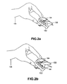
- FIG. 2 a illustrates the isometric view of the user 106 adjusting the first element 102 into the second element 104 of the adjustable paper clip 100 .
- FIG. 2 b illustrates the isometric view of the adjusted second element 104 at the first gear a 1 of the first element 102 .
- FIG. 3 a illustrates the side view of the adjustable paper clip 100 .
- FIG. 3 b illustrates the isometric view of the adjustable paper clip 100 opened at a distance of D 1 .
- FIG. 4 illustrates the isometric view of the adjusted second element 104 at the third gear c 3 of the first element 102 .
- FIG. 5 illustrates the isometric view of the adjustable paper clip 100 opened at a distance of D 2 .
- FIG. 1 a illustrates the isometric view of the adjustable paper clip 100 comprising of two curved elements, the first element 102 and the second element 104 .
- the first element 102 comprises of a handle 101 and at least one male member, more preferably three male members 102 a , 102 b and 102 c having first end 102 a 1 , 102 b 1 and 102 c 1 integrally attached to the first element 102 and second end of male members as a curved surface 102 a 2 , 102 b 2 and 102 c 2 .
- Each of the three male members 102 a , 102 b and 102 c further comprises of at least one gear more preferably three gear [a 1 , b 1 , c 1 ], [a 2 , b 2 , c 2 ] and [a 3 , b 3 and c 3 ] for making adjustments in the adjustable paper clip.
- the second element 104 comprises of a handle 103 and at least one female member, more preferably three female members 104 a , 104 b and 104 c .
- the breadth of the curved surfaces 102 a 2 , 102 b 2 and 102 c 2 of male members 102 a , 102 b and 102 c is kept more than breadth of opening of the female members 104 a , 104 b and 104 c .
- the pressure exerted by the curved surfaces 102 a 2 , 102 b 2 and 102 c 2 on the opening of the female member 104 a , 104 b and 104 c respectively ensures that the first element 102 and second element 104 does not separate and fall apart.
- the second end 105 a of the first element 102 and the second end 105 b of second element 104 form a gripper of the adjustable paper grip.
- FIG. 1 b illustrates the view representing the first element 102 of the adjustable paper clip 100 .
- Each male member 102 a , 102 b and 102 c comprises at least one gear, more preferably three gears [a 1 , b 1 and c 1 ], [a 2 , b 2 and c 2 ] and [a 3 , b 3 and c 3 ] respectively.
- FIG. 2 a illustrates the isometric view of the user 106 adjusting the first element 102 and the second element 104 of the adjustable paper clip 100 which enables the male members 102 a , 102 b and 102 c of first element 102 to slide into the respective female members 104 a , 104 b and 104 c of the second element 104 .
- FIG. 2 b illustrates the isometric view of the adjusted second element 104 at the first gear a 1 , a 2 and a 3 of the first element 102 .
- the user 106 adjusts the female member 104 a , 104 b and 104 c onto the first gear a 1 , a 2 and a 3 of the respective male members 102 a , 102 b and 102 c.
- FIG. 3 a illustrates the side view of the adjustable paper clip 100 opened by the user 106 .
- the user 106 is enabled to open the adjustable paper clip 100 using handles 101 and 103 .
- FIG. 3 b illustrates the isometric view of the adjustable paper clip 100 opened at a distance D 1 .
- the adjustable paper clip 100 is opened at the distance D 1 when the user 106 opens the second end 105 a of the first element and second end 105 b of the second element using handles 101 and 103 .
- FIG. 4 illustrates the isometric view of the adjusted second element 104 at the third gear c 1 , c 2 , and c 3 of the first element 102 of adjustable paper clip 100 .
- the user 106 adjusts the female members 104 a , 104 b and 104 c onto the third gear c 1 , c 2 and c 3 of the respective male members 102 a , 102 b and 102 c.
- FIG. 5 illustrates the isometric view of the adjustable paper clip 100 opened a distance D 2 .
- the adjustable paper clip 100 is opened at the distance D 2 when the user 106 opens the second end 105 a of the first element and second end 105 b of the second element using handles 101 and 103 .
- the user 106 wants to grip a desired size of paper bundle using the adjustable paper clip 100 .
- the user 106 holds the first element 102 of the adjustable paper clip 100 and starts adjusting the male members 102 a , 102 b and 102 c into the respective female members 104 a , 104 b and 104 c of the second element 104 .
- the user selects the appropriate gear, for example first gear a 1 , a 2 and a 3 of male members 102 a , 102 b and 102 c respectively and adjust it with the female member 104 a , 104 b and 104 c thereby enabling the user to move the handles 101 and 103 at a greater distance.
- the pressure exerted by the curved surfaces 102 a 2 , 102 b 2 , and 102 c 2 on the female member 104 a , 104 b and 104 c respectively ensures that the first element 102 and second element 104 does not separate and fall apart. Further, the actuation enables the spring (not shown) to compress and opens the second end 105 a of the first element 102 and second end 105 b the second element 104 at a required distance to grip the desired size of paper bundle.
- the user 106 wants to grip small size of paper bundle for example bundle containing 2-50 papers, the user holds the first element 102 of the adjustable paper clip 100 and start sliding the male members 102 a , 102 b and 102 c into the female members 104 a , 104 b and 104 c of second element 104 until the edges of the female members 104 a , 104 b and 104 c are adjusted onto the third gear c 1 , c 2 and c 3 of the male members 102 a , 102 b and 102 c respectively.
- the user 106 actuates the handles 101 and 103 of the adjustable paper clip 100 which facilitates the second end 105 a of the first element 102 and second end 105 b the second element 104 to open at the distance D 1 and grip the desired size of paper bundle with the help of the adjustable paper clip 100 .
- the user 106 wants to grip bigger size of paper bundle for example bundle containing more than 50-75 papers, the user holds the first element 102 of the adjustable paper clip 100 and start sliding the male members 102 a , 102 b and 102 c into the female members 104 a , 104 b and 104 c of second element 104 until the edges of the female members 104 a , 104 b and 104 c are adjusted on the first gear a 1 , a 2 and a 3 of the male members 102 a , 102 b and 102 c .
- the user 106 actuates the handles 101 and 103 of the adjustable paper clip 100 which facilitates second end 105 a of the first element 102 and second end 105 b the second element 104 to open at the distance D 1 and grip the desired size of the paper bundle with the help of the adjustable paper clip 100 .
- the user 106 continuously adjusts the first element 102 into the second element 104 of the adjustable paper clip 100 for obtaining a required distance of the second ends 105 a of the first element 102 and second end 105 b the second element 104 to open at a desired distance for different size of paper pile.
Abstract
The present invention relates to an adjustable paper clip which facilitates the user to grip desired size of paper bundle. The user makes adjustments in the first element of an adjustable paper clip to enable the user to open it at a required distance for gripping the desired size of paper bundle.
Description
Presently there are varieties of clamping devices available to grip paper bundle such as staplers, clip board pins, paper clips and the like. It is often observed that, the use of staplers and clipboard pins causes damage to the paper and thus put impression of pins or staplers on it which is highly undesirable. Also, the staplers have a limitation as they are restricted to staple a limited size of paper bundle. In such case, bigger stapler is desired in order to staple a bigger size of paper bundle which is undesirable for the user.
The other extensively used clamping device is a paper clip and is available in the two most pervasive forms. One, it is available as a loop of wire with a single loop facing in one direction and a pair of nesting loops facing in the other direction and two, as a two steel wires attached to a steel strip at their front end making an isometric triangle for griping the paper bundle. However, the limitations with these conventional paper clips are their sizes which enable them to grip a limited size of paper bundle. The user has to purchase a bigger size of paper clip to grip bigger paper bundle. Thus, the user has to buy different variants of paper clips in accordance with the size of paper bundle which is highly undesirable.
In prior art U.S. Pat. No. 4,920,614, the inventor proposes a plastic paper clip which is adjusted by sliding the clamping plate on it. However, the drawback of this invention is the clamping device has a limited area to slide and thus restricting the opening of a paper clip at a certain distance thereby making it undesirable to grip larger paper bundle.
In yet another prior art U.S. Pat. No. 7,500,301, the inventor proposes two clamping elements which are adjusted by sliding an adjustable thickness mean Since the adjustable thickness mean allows the paper clip to open at a certain angle, this paper clip has a restriction of gripping only limited size of paper bundle.
In yet another prior art CN203077901U, the inventor proposes the user to adjust the paper clip by adjusting nut and bolt of the paper clip. The user has to adjust the bolt to adjust the height of the paper clip in order to grip required size of paper bundle. Therefore, the user has a restriction of using this paper clip according to the height of the bolt.
Thus, there remains a need to eliminate the above mentioned shortcomings in the existing prior art. Therefore, the present invention facilitates the user to have an adjustable paper clip which enables the user to grip different size of paper bundle by sliding the first element of the adjustable paper clip into the second element.
The main objective of present invention is to provide an adjustable paper clip which eliminates the shortcomings of the prior art and facilitates the user to grip desired size of paper bundle.
In order to achieve the above mentioned objective, the present invention provides an adjustable paper clip comprising of two elements, the first element and the second element. Wherein, the first end of the first element comprises of a handle and at least one male member having different adjustment gear on them. Further, the first end of the second element comprises of a handle and at least one female member. The second end of both the first element and the second element forms a gripper which enables to grip the paper bundle
In an embodiment, the user slides the female member into an appropriate gear of the male member so as to open the second end of both the first element and the second element at a desired distance. Thereafter, the adjustable paper clip is enabled to grip desired size of paper bundle.
Reference will now be made in detail to the exemplary embodiment (s) of the invention, examples of which are illustrated in the accompanying drawings. Whenever possible, the same reference numerals will be used throughout the drawings to refer to the same or like parts.
In the preferred embodiment, the user 106 wants to grip a desired size of paper bundle using the adjustable paper clip 100. The user 106 holds the first element 102 of the adjustable paper clip 100 and starts adjusting the male members 102 a, 102 b and 102 c into the respective female members 104 a, 104 b and 104 c of the second element 104. The user selects the appropriate gear, for example first gear a1, a2 and a3 of male members 102 a, 102 b and 102 c respectively and adjust it with the female member 104 a, 104 b and 104 c thereby enabling the user to move the handles 101 and 103 at a greater distance. Moreover, The pressure exerted by the curved surfaces 102 a 2, 102 b 2, and 102 c 2 on the female member 104 a, 104 b and 104 c respectively ensures that the first element 102 and second element 104 does not separate and fall apart. Further, the actuation enables the spring (not shown) to compress and opens the second end 105 a of the first element 102 and second end 105 b the second element 104 at a required distance to grip the desired size of paper bundle.
In an embodiment, the user 106 wants to grip small size of paper bundle for example bundle containing 2-50 papers, the user holds the first element 102 of the adjustable paper clip 100 and start sliding the male members 102 a, 102 b and 102 c into the female members 104 a, 104 b and 104 c of second element 104 until the edges of the female members 104 a, 104 b and 104 c are adjusted onto the third gear c1, c2 and c3 of the male members 102 a, 102 b and 102 c respectively. Thereafter, the user 106 actuates the handles 101 and 103 of the adjustable paper clip 100 which facilitates the second end 105 a of the first element 102 and second end 105 b the second element 104 to open at the distance D1 and grip the desired size of paper bundle with the help of the adjustable paper clip 100.
In another embodiment, the user 106 wants to grip bigger size of paper bundle for example bundle containing more than 50-75 papers, the user holds the first element 102 of the adjustable paper clip 100 and start sliding the male members 102 a, 102 b and 102 c into the female members 104 a, 104 b and 104 c of second element 104 until the edges of the female members 104 a, 104 b and 104 c are adjusted on the first gear a1, a2 and a3 of the male members 102 a, 102 b and 102 c. Thereafter, the user 106 actuates the handles 101 and 103 of the adjustable paper clip 100 which facilitates second end 105 a of the first element 102 and second end 105 b the second element 104 to open at the distance D1 and grip the desired size of the paper bundle with the help of the adjustable paper clip 100.
In yet another embodiment, the user 106 continuously adjusts the first element 102 into the second element 104 of the adjustable paper clip 100 for obtaining a required distance of the second ends 105 a of the first element 102 and second end 105 b the second element 104 to open at a desired distance for different size of paper pile.
Although the exemplary embodiments of the present invention have been described for illustrative purposes, those skilled in the art will appreciate the adjustable paper clip 100 with multiple gears for gripping the required size of paper bundle thus eliminating the efforts of the user to purchase different variants of paper clips.
Claims (5)
1. A user adjustable paper clip, configured to grip a paper bundle, comprising:
a. a first curved element, further comprising a handle and a plurality of male members, wherein a single male member further comprises a first end, a second curved end, and a plurality of gears, such that the first end of the single male member is integrally connected to the first curved element; and
b. a second curved element, further comprising a handle and a plurality of female members at a first end of the second curved element, wherein the plurality of female members is configured to slide onto the plurality of male members correspondingly,
so as to adjust the distance between the first end of the single male member integrally connected to the first curved element and the first end of the second curved element in accordance with the desired size of the paper bundle; and pressure exerted by the second curved end of the single male member on a single female member respectively ensures that the first curved element and the second curved element do not separate.
2. The user adjustable paper clip of claim 1 , wherein the first curved element and the second curved element are made up of plastic or any combination of plastic and steel.
3. The user adjustable paper clip of claim 1 , wherein the breadth of the second curved end of the single male member of the first curved element is greater than the breadth of the single female member of the second curved element so as to keep the first curved element and the second curved element together and prevent separation.
4. The user adjustable paper clip of any of the claims 1 -3 , wherein the plurality of gears of the single male member of the first curved element is equal to three.
5. The user adjustable paper clip of any of the claim 1 -3 , wherein the plurality of male members and the plurality of female members is equal to three.
Priority Applications (1)
| Application Number | Priority Date | Filing Date | Title |
|---|---|---|---|
| US14/804,335 US9446620B1 (en) | 2015-07-21 | 2015-07-21 | User adjustable paper clip |
Applications Claiming Priority (1)
| Application Number | Priority Date | Filing Date | Title |
|---|---|---|---|
| US14/804,335 US9446620B1 (en) | 2015-07-21 | 2015-07-21 | User adjustable paper clip |
Publications (1)
| Publication Number | Publication Date |
|---|---|
| US9446620B1 true US9446620B1 (en) | 2016-09-20 |
Family
ID=56896028
Family Applications (1)
| Application Number | Title | Priority Date | Filing Date |
|---|---|---|---|
| US14/804,335 Active US9446620B1 (en) | 2015-07-21 | 2015-07-21 | User adjustable paper clip |
Country Status (1)
| Country | Link |
|---|---|
| US (1) | US9446620B1 (en) |
Cited By (3)
| Publication number | Priority date | Publication date | Assignee | Title |
|---|---|---|---|---|
| CN110667280A (en) * | 2018-07-03 | 2020-01-10 | 徐辉祥 | Financial billing folder |
| US20210052273A1 (en) * | 2018-02-12 | 2021-02-25 | Institute For Cancer Research D/B/A The Research Institute Of Fox Chase Cancer Center | Tensionable Surgical Clamp |
| US20240042789A1 (en) * | 2020-12-17 | 2024-02-08 | Chun Ki Kim | Non-slip assembly for binder clip |
Citations (4)
| Publication number | Priority date | Publication date | Assignee | Title |
|---|---|---|---|---|
| US3324864A (en) | 1964-09-28 | 1967-06-13 | Danel Jewelry Co | Ornamental hair clip |
| US4920614A (en) | 1982-01-23 | 1990-05-01 | Tatusabu Tsukamoto | Clamping device |
| US5638583A (en) * | 1995-12-29 | 1997-06-17 | Tseng; E-San | Paper clip |
| US7500301B2 (en) | 2003-05-02 | 2009-03-10 | Ergo Industrial Seating Systems Inc | Method of clamping paper in a paper clip |
-
2015
- 2015-07-21 US US14/804,335 patent/US9446620B1/en active Active
Patent Citations (4)
| Publication number | Priority date | Publication date | Assignee | Title |
|---|---|---|---|---|
| US3324864A (en) | 1964-09-28 | 1967-06-13 | Danel Jewelry Co | Ornamental hair clip |
| US4920614A (en) | 1982-01-23 | 1990-05-01 | Tatusabu Tsukamoto | Clamping device |
| US5638583A (en) * | 1995-12-29 | 1997-06-17 | Tseng; E-San | Paper clip |
| US7500301B2 (en) | 2003-05-02 | 2009-03-10 | Ergo Industrial Seating Systems Inc | Method of clamping paper in a paper clip |
Cited By (5)
| Publication number | Priority date | Publication date | Assignee | Title |
|---|---|---|---|---|
| US20210052273A1 (en) * | 2018-02-12 | 2021-02-25 | Institute For Cancer Research D/B/A The Research Institute Of Fox Chase Cancer Center | Tensionable Surgical Clamp |
| US11944319B2 (en) * | 2018-02-12 | 2024-04-02 | Institute For Cancer Research | Tensionable surgical clamp |
| CN110667280A (en) * | 2018-07-03 | 2020-01-10 | 徐辉祥 | Financial billing folder |
| US20240042789A1 (en) * | 2020-12-17 | 2024-02-08 | Chun Ki Kim | Non-slip assembly for binder clip |
| US11932045B2 (en) * | 2020-12-17 | 2024-03-19 | Chun Ki Kim | Non-slip assembly for binder clip |
Similar Documents
| Publication | Publication Date | Title |
|---|---|---|
| US9446620B1 (en) | User adjustable paper clip | |
| US6892609B2 (en) | Pliers with movable joint | |
| US20120297938A1 (en) | Pliers with quickly adjustable gripping jaws | |
| US8925157B2 (en) | Front to back reversible multiple planar paper clip with double clipping effect | |
| US20080073822A1 (en) | Angle corner clamp | |
| US20210088108A1 (en) | Adjustable bungee fastener | |
| US10123619B2 (en) | Canvas holding assembly | |
| CN108348050A (en) | Rope clamping element and rope clamping device | |
| US9534660B2 (en) | Clamping members and clamping devices | |
| US3845521A (en) | Resilient devices for temporarily binding and gripping the edge of materials | |
| US20160366895A1 (en) | Uniform Dough Rolling System | |
| US892503A (en) | Wrench. | |
| US9180556B2 (en) | Auxiliary clamping system for welding operation | |
| US6491294B1 (en) | Perpendicular bar clamp | |
| US20080216615A1 (en) | Structure of pliers | |
| US6978704B2 (en) | Locking pliers | |
| US7174608B2 (en) | Methods and apparatus for gripping articles | |
| CN206811784U (en) | A kind of quick regulation folder away from fixture | |
| EP3517791B1 (en) | Clamping device, clamping system with clamping device and control wire loop, artifical tree system comprising such clampnig system | |
| CN110843379B (en) | Loose-leaf binding device | |
| TW201618904A (en) | Pipe wrench structure | |
| CN202174515U (en) | Pliers with turnover jaws | |
| US20220226967A1 (en) | Connector Tool Assembly | |
| JP2001105773A (en) | Clip | |
| CN102729165A (en) | Turnover jaw pliers |
Legal Events
| Date | Code | Title | Description |
|---|---|---|---|
| STCF | Information on status: patent grant |
Free format text: PATENTED CASE |
|
| FEPP | Fee payment procedure |
Free format text: MAINTENANCE FEE REMINDER MAILED (ORIGINAL EVENT CODE: REM.); ENTITY STATUS OF PATENT OWNER: MICROENTITY |
|
| FEPP | Fee payment procedure |
Free format text: SURCHARGE FOR LATE PAYMENT, MICRO ENTITY (ORIGINAL EVENT CODE: M3554); ENTITY STATUS OF PATENT OWNER: MICROENTITY |
|
| MAFP | Maintenance fee payment |
Free format text: PAYMENT OF MAINTENANCE FEE, 4TH YEAR, MICRO ENTITY (ORIGINAL EVENT CODE: M3551); ENTITY STATUS OF PATENT OWNER: MICROENTITY Year of fee payment: 4 |