US9444713B1 - Cut-through routing for network devices - Google Patents
Cut-through routing for network devices Download PDFInfo
- Publication number
- US9444713B1 US9444713B1 US13/678,086 US201213678086A US9444713B1 US 9444713 B1 US9444713 B1 US 9444713B1 US 201213678086 A US201213678086 A US 201213678086A US 9444713 B1 US9444713 B1 US 9444713B1
- Authority
- US
- United States
- Prior art keywords
- port
- packet
- sub
- ports
- cut
- Prior art date
- Legal status (The legal status is an assumption and is not a legal conclusion. Google has not performed a legal analysis and makes no representation as to the accuracy of the status listed.)
- Active, expires
Links
- 238000000034 method Methods 0.000 claims abstract description 48
- 230000005055 memory storage Effects 0.000 claims abstract description 12
- 239000000835 fiber Substances 0.000 claims description 48
- 230000008569 process Effects 0.000 claims description 36
- 239000000872 buffer Substances 0.000 description 19
- 238000012545 processing Methods 0.000 description 11
- 239000004744 fabric Substances 0.000 description 8
- 238000010586 diagram Methods 0.000 description 5
- 238000012546 transfer Methods 0.000 description 4
- 230000005540 biological transmission Effects 0.000 description 3
- 238000004364 calculation method Methods 0.000 description 3
- 238000004891 communication Methods 0.000 description 3
- 238000004590 computer program Methods 0.000 description 3
- 230000001276 controlling effect Effects 0.000 description 3
- 229910000078 germane Inorganic materials 0.000 description 3
- 238000012986 modification Methods 0.000 description 3
- 230000004048 modification Effects 0.000 description 3
- 230000006855 networking Effects 0.000 description 3
- 230000002093 peripheral effect Effects 0.000 description 3
- 238000010276 construction Methods 0.000 description 2
- 238000013461 design Methods 0.000 description 2
- 230000006870 function Effects 0.000 description 2
- 230000005291 magnetic effect Effects 0.000 description 2
- 239000003607 modifier Substances 0.000 description 2
- 230000003287 optical effect Effects 0.000 description 2
- 238000007781 pre-processing Methods 0.000 description 2
- 238000013459 approach Methods 0.000 description 1
- 238000004422 calculation algorithm Methods 0.000 description 1
- 125000004122 cyclic group Chemical group 0.000 description 1
- 230000003111 delayed effect Effects 0.000 description 1
- 230000009977 dual effect Effects 0.000 description 1
- 238000005538 encapsulation Methods 0.000 description 1
- 238000005516 engineering process Methods 0.000 description 1
- 230000003993 interaction Effects 0.000 description 1
- 238000004519 manufacturing process Methods 0.000 description 1
- 229920000729 poly(L-lysine) polymer Polymers 0.000 description 1
- 238000003672 processing method Methods 0.000 description 1
- 230000001105 regulatory effect Effects 0.000 description 1
- 238000000926 separation method Methods 0.000 description 1
- 230000003068 static effect Effects 0.000 description 1
Images


Classifications
-
- H—ELECTRICITY
- H04—ELECTRIC COMMUNICATION TECHNIQUE
- H04L—TRANSMISSION OF DIGITAL INFORMATION, e.g. TELEGRAPHIC COMMUNICATION
- H04L67/00—Network arrangements or protocols for supporting network services or applications
- H04L67/01—Protocols
- H04L67/10—Protocols in which an application is distributed across nodes in the network
- H04L67/1097—Protocols in which an application is distributed across nodes in the network for distributed storage of data in networks, e.g. transport arrangements for network file system [NFS], storage area networks [SAN] or network attached storage [NAS]
-
- H—ELECTRICITY
- H04—ELECTRIC COMMUNICATION TECHNIQUE
- H04L—TRANSMISSION OF DIGITAL INFORMATION, e.g. TELEGRAPHIC COMMUNICATION
- H04L43/00—Arrangements for monitoring or testing data switching networks
- H04L43/08—Monitoring or testing based on specific metrics, e.g. QoS, energy consumption or environmental parameters
- H04L43/0876—Network utilisation, e.g. volume of load or congestion level
- H04L43/0888—Throughput
-
- H—ELECTRICITY
- H04—ELECTRIC COMMUNICATION TECHNIQUE
- H04L—TRANSMISSION OF DIGITAL INFORMATION, e.g. TELEGRAPHIC COMMUNICATION
- H04L41/00—Arrangements for maintenance, administration or management of data switching networks, e.g. of packet switching networks
- H04L41/08—Configuration management of networks or network elements
- H04L41/0803—Configuration setting
- H04L41/0823—Configuration setting characterised by the purposes of a change of settings, e.g. optimising configuration for enhancing reliability
-
- H—ELECTRICITY
- H04—ELECTRIC COMMUNICATION TECHNIQUE
- H04L—TRANSMISSION OF DIGITAL INFORMATION, e.g. TELEGRAPHIC COMMUNICATION
- H04L41/00—Arrangements for maintenance, administration or management of data switching networks, e.g. of packet switching networks
- H04L41/14—Network analysis or design
- H04L41/142—Network analysis or design using statistical or mathematical methods
-
- H—ELECTRICITY
- H04—ELECTRIC COMMUNICATION TECHNIQUE
- H04L—TRANSMISSION OF DIGITAL INFORMATION, e.g. TELEGRAPHIC COMMUNICATION
- H04L5/00—Arrangements affording multiple use of the transmission path
- H04L5/0001—Arrangements for dividing the transmission path
- H04L5/0003—Two-dimensional division
- H04L5/0005—Time-frequency
- H04L5/0007—Time-frequency the frequencies being orthogonal, e.g. OFDM(A), DMT
-
- H—ELECTRICITY
- H04—ELECTRIC COMMUNICATION TECHNIQUE
- H04L—TRANSMISSION OF DIGITAL INFORMATION, e.g. TELEGRAPHIC COMMUNICATION
- H04L67/00—Network arrangements or protocols for supporting network services or applications
- H04L67/01—Protocols
- H04L67/10—Protocols in which an application is distributed across nodes in the network
-
- H—ELECTRICITY
- H04—ELECTRIC COMMUNICATION TECHNIQUE
- H04L—TRANSMISSION OF DIGITAL INFORMATION, e.g. TELEGRAPHIC COMMUNICATION
- H04L67/00—Network arrangements or protocols for supporting network services or applications
- H04L67/50—Network services
- H04L67/60—Scheduling or organising the servicing of application requests, e.g. requests for application data transmissions using the analysis and optimisation of the required network resources
-
- H—ELECTRICITY
- H04—ELECTRIC COMMUNICATION TECHNIQUE
- H04L—TRANSMISSION OF DIGITAL INFORMATION, e.g. TELEGRAPHIC COMMUNICATION
- H04L69/00—Network arrangements, protocols or services independent of the application payload and not provided for in the other groups of this subclass
- H04L69/08—Protocols for interworking; Protocol conversion
-
- H—ELECTRICITY
- H04—ELECTRIC COMMUNICATION TECHNIQUE
- H04L—TRANSMISSION OF DIGITAL INFORMATION, e.g. TELEGRAPHIC COMMUNICATION
- H04L69/00—Network arrangements, protocols or services independent of the application payload and not provided for in the other groups of this subclass
- H04L69/18—Multiprotocol handlers, e.g. single devices capable of handling multiple protocols
-
- H—ELECTRICITY
- H04—ELECTRIC COMMUNICATION TECHNIQUE
- H04L—TRANSMISSION OF DIGITAL INFORMATION, e.g. TELEGRAPHIC COMMUNICATION
- H04L69/00—Network arrangements, protocols or services independent of the application payload and not provided for in the other groups of this subclass
- H04L69/22—Parsing or analysis of headers
-
- H—ELECTRICITY
- H04—ELECTRIC COMMUNICATION TECHNIQUE
- H04L—TRANSMISSION OF DIGITAL INFORMATION, e.g. TELEGRAPHIC COMMUNICATION
- H04L69/00—Network arrangements, protocols or services independent of the application payload and not provided for in the other groups of this subclass
- H04L69/28—Timers or timing mechanisms used in protocols
-
- H—ELECTRICITY
- H04—ELECTRIC COMMUNICATION TECHNIQUE
- H04N—PICTORIAL COMMUNICATION, e.g. TELEVISION
- H04N21/00—Selective content distribution, e.g. interactive television or video on demand [VOD]
- H04N21/20—Servers specifically adapted for the distribution of content, e.g. VOD servers; Operations thereof
- H04N21/23—Processing of content or additional data; Elementary server operations; Server middleware
- H04N21/238—Interfacing the downstream path of the transmission network, e.g. adapting the transmission rate of a video stream to network bandwidth; Processing of multiplex streams
- H04N21/2381—Adapting the multiplex stream to a specific network, e.g. an Internet Protocol [IP] network
-
- H—ELECTRICITY
- H04—ELECTRIC COMMUNICATION TECHNIQUE
- H04W—WIRELESS COMMUNICATION NETWORKS
- H04W28/00—Network traffic management; Network resource management
- H04W28/02—Traffic management, e.g. flow control or congestion control
- H04W28/06—Optimizing the usage of the radio link, e.g. header compression, information sizing, discarding information
-
- H—ELECTRICITY
- H04—ELECTRIC COMMUNICATION TECHNIQUE
- H04L—TRANSMISSION OF DIGITAL INFORMATION, e.g. TELEGRAPHIC COMMUNICATION
- H04L49/00—Packet switching elements
- H04L49/90—Buffering arrangements
-
- H—ELECTRICITY
- H04—ELECTRIC COMMUNICATION TECHNIQUE
- H04Q—SELECTING
- H04Q11/00—Selecting arrangements for multiplex systems
- H04Q11/0001—Selecting arrangements for multiplex systems using optical switching
- H04Q11/0062—Network aspects
- H04Q11/0066—Provisions for optical burst or packet networks
Definitions
- the present disclosure relates to networks and network devices.
- Networking systems are commonly used to move network information (which may also be referred to interchangeably, as frames, packets or commands) between computing systems (for example, servers) or between computing systems and network devices (for example, storage systems).
- network information which may also be referred to interchangeably, as frames, packets or commands
- computing systems for example, servers
- network devices for example, storage systems
- Various hardware and software components are used to implement network communication.
- a network switch is typically a multi-port device where each port manages a point-to-point connection between itself and an attached system. Each port can be attached to a server, peripheral, input/output subsystem, bridge, hub, router, or another switch.
- the term network switch as used herein includes a Multi-Level switch that uses plural switching elements within a single switch chassis to route data packets. Different network and storage protocols may be used to handle network information and storage information. Continuous efforts are being made to enhance the use of networking and storage protocols.
- a network device having a plurality of base-ports, where each base-port is coupled to a plurality of network links and each base-port has a plurality of sub-ports configured to operate independently as a port for sending and receiving information using one of the plurality of network links at a plurality of rates complying with a plurality of protocols is provided.
- the network device comprises a temporary memory storage device having a plurality of storage locations that are used to store packets received by the plurality of sub-ports; wherein the memory storage device is shared among the plurality of sub-ports such that each sub-port is provided access to one or more storage locations at a certain phase of a system clock cycle for the network device; and a cut-through estimation circuit that estimates a cut-through threshold value based on a certain portion of a packet that has to be received and stored at one of the plurality of storage locations before the packet can be processed by one of the sub-ports that received the frame;
- the cut-through threshold value varies based on an operating speed of a network link the packet is received on, an operating speed of a network link the packet is transmitted from, and a protocol used for receiving and transmitting the packet; and the cut-through estimation circuit uses a first value and a second value to shift a maximum packet length for the packet, where the first value and the second value are obtained from a data structure and vary based on the operating speed of the network link the packet is received on and the operating speed of the network link the packet is transmitted on to its destination
- a machine implemented method includes receiving a packet at a sub-port from among a plurality of sub-ports of a base port of a network device, where the plurality of sub-ports can be configured to operate at more than one operating speed to process packets complying with different protocols; temporarily storing the packet at a temporary memory storage device having a plurality of storage locations shared among the plurality of sub-ports such that each sub-port is provided access to one or more storage locations within a certain phase of a system clock cycle for the network device; estimating a cut-through threshold value based on which a certain portion of the packet has to be received and stored at one of the plurality of storage locations before the packet can be processed by the network device.
- the cut-through threshold value varies based on an operating speed of a network link the packet is received on, an operating speed of a network link the packet is transmitted on and a protocol used for receiving and transmitting the packet. Furthermore, the cut-through threshold value is estimated by using a first value and a second value to shift a maximum frame length for the frame, where the first value and the second value are obtained from a data structure and vary based on the operating speed of the network link the packet is received on and the operating speed of the network link the frame is transmitted on to its destination.
- a computing system coupled to a network device includes a plurality of base-ports, where each base-port is coupled to a plurality of network links and each base-port has a plurality of sub-ports configured to operate independently as a port for sending and receiving information using one of the plurality of network links at a plurality of rates complying with a plurality of protocols; a temporary memory storage device having a plurality of storage locations that are used to store packets received by the plurality of sub-ports; wherein the memory storage device is shared among the plurality of sub-ports such that each sub-port is provided access to one or more storage locations at a certain phase of a system clock cycle for the network device; and a cut-through estimation circuit that estimates a cut-through threshold value based on which a certain portion of a packet has to be received and stored at one of the plurality of storage locations before the packet can be processed by one of the sub-ports that received the frame.
- the cut-through threshold value varies based on an operating speed of a network link the packet is received on, an operating speed of a network link the packet is transmitted from and a protocol used for receiving and transmitting the packet. Furthermore, the cut-through estimation circuit uses a first value and a second value to shift a maximum packet length for the packet, where the first value and the second value are obtained from a data structure and vary based on the operating speed of the network link the packet is received and the operating speed of the network link the packet is transmitted to its destination.
- FIG. 1 is a functional block diagram of a network that the present embodiments may be used in connection with;
- FIG. 2A is a functional block diagram of a switch element according to the present embodiments.
- FIGS. 2B-2C are functional block diagrams of a receive segment, according to one embodiment
- FIGS. 3A-3C are examples of frame (or packet, used interchangeably throughout this specification) formats for frames that are routed by the switch element of FIG. 2A ;
- FIG. 4A is a functional block diagram of a cut-through circuit, according to one embodiment:
- FIG. 4B is a data structure used by the cut-through circuit of FIG. 4A ;
- FIG. 4C is a flowchart illustrating a method of using the cut-through circuit, of FIG. 4A according to one embodiment.
- FIG. 5 is a flowchart illustrating one embodiment of a method for determining “n” and “m” values in the data structure of FIG. 4B .
- any of the embodiments described with reference to the figures may be implemented using software, firmware, hardware (e.g., fixed logic circuitry), manual processing, or a combination of these implementations.
- the terms “logic.” “module,” “component,” “system” and “functionality,” as used herein, generally represent software, firmware, hardware, or a combination of these elements.
- the terms “logic,” “module,” “component,” “system,” and “functionality” represent program code that performs specified tasks when executed on a processing device or devices (e.g., CPU or CPUs).
- the program code can be stored in one or more computer readable memory devices.
- the illustrated separation of logic, modules, components, systems, and functionality into distinct units may reflect an actual physical grouping and allocation of software, firmware, and/or hardware, or can correspond to a conceptual allocation of different tasks performed by a single software program, firmware program, and/or hardware unit.
- the illustrated logic, modules, components, systems, and functionality may be located at a single site (e.g., as implemented by a processing device), or may be distributed over a plurality of locations.
- machine-readable media refers to any kind of non-transitory medium for retaining information in any form, including various kinds of storage devices (magnetic, optical, static, etc.).
- the embodiments disclosed herein may be implemented as a computer process (method), a computing system, or as an article of manufacture, such as a computer program product or non-transitory computer-readable media.
- the computer program product may be computer storage media, readable by a computer device, and encoding a computer program of instructions for executing a computer process.
- FC Fibre Channel
- FCoE Fibre Channel over Ethernet
- Ethernet Ethernet
- FC Fibre Channel
- FCoE Fibre Channel over Ethernet
- Ethernet Ethernet
- FCoE Fibre Channel over Ethernet
- Fibre Channel is a set of American National Standards Institute (ANSI) standards. Fibre Channel provides a serial transmission protocol for storage and network protocols such as HIPPI, SCSI, IP, ATM and others. Fibre Channel provides an input/output interface to meet the requirements of both Channel and network users.
- the Fibre Channel standards are incorporated herein by reference in their entirety.
- Fibre Channel supports three different topologies: point-to-point, arbitrated loop and Fibre Channel Fabric.
- the point-to-point topology attaches two devices directly.
- the arbitrated loop topology attaches devices in a loop.
- the Fabric topology attaches computing systems directly to a Fabric, which are then connected to multiple devices.
- the Fibre Channel Fabric topology allows several media types to be interconnected.
- a Fibre Channel switch is a multi-port device where each port manages a point-to-point connection between itself and its attached system. Each port can be attached to a server, peripheral. I/O subsystem, bridge, hub, router, or even another switch. A switch receives messages from one port and routes them to other ports. Fibre Channel switches use memory buffers to hold frames received and sent across a network. Associated with these buffers are credits, which are the number of frames that a buffer can hold per Fabric port.
- Ethernet is a family of computer networking technologies for local area networks (LANs). Systems communicating over Ethernet divide a stream of data into individual packets called frames. Each frame contains source and destination addresses and error-checking data so that damaged data can be detected and re-transmitted. Ethernet is standardized in IEEE 802.3, which is incorporated herein by reference in its entirety.
- Fibre Channel over Ethernet is a converged network and storage protocol for handling both network and storage traffic.
- the FCoE standard enables network adapters and network switches to handle both network and storage traffic using network and storage protocols.
- Fibre Channel frames are encapsulated in Ethernet frames. Encapsulation allows Fibre Channel to use 1 Gigabit Ethernet networks (or higher speeds) while preserving the Fibre Channel protocol.
- Cloud computing pertains to computing capability that provides an abstraction between the computing resource and its underlying technical architecture (e.g., servers, storage, networks), enabling convenient, on-demand network access to a shared pool of configurable computing resources that can be rapidly provisioned and released with minimal management effort or service provider interaction.
- the term “cloud” is intended to refer to the Internet and cloud computing allows shared resources, for example, software and information, to be available, on-demand, like a public utility.
- Typical cloud computing providers deliver common business applications online, which are accessed from another web service or software like a web browser, while the software and data are stored remotely on servers.
- the cloud computing architecture uses a layered approach for providing application services.
- a first layer is an application layer that is executed at client computers.
- the application allows a client to access storage via a cloud.
- the application layer is a cloud platform and cloud infrastructure, followed by a “server” layer that includes hardware and computer software designed for cloud-specific services.
- FIG. 1 illustrates an example of a system 100 that may be used in connection with the present embodiments.
- System 100 may include a computing system 102 , which may be referred to as a host system.
- a typical host system 102 includes several functional components, including a central processing unit (CPU) (also referred to as a processor or processing module) 104 , a host memory (or main/system memory) 106 , a storage device 108 , a display 110 , input/output (“I/O”) device(s) 112 , and other components (or devices).
- the host memory 106 is coupled to the processor 104 via a system bus or a local memory bus 114 .
- the processor 104 may be, or may include, one or more programmable general-purpose or special-purpose microprocessors, digital signal processors (DSPs), programmable controllers, application specific integrated circuits (ASICs), programmable logic devices (PLDs), or the like, or a combination of such hardware-based devices.
- DSPs digital signal processors
- ASICs application specific integrated circuits
- PLDs programmable logic devices
- the host memory 106 provides the processor 104 access to data and program information that is stored in the host memory 106 at execution time.
- the host memory 106 includes random access memory (RAM) circuits, read-only memory (ROM), flash memory, or the like, or a combination of such devices.
- the storage device 108 may comprise one or more internal and/or external mass storage devices, which may be or may include any conventional medium for storing large volumes of data in a non-volatile manner.
- the storage device 108 may include conventional magnetic disks, optical disks such as CD-ROM or DVD-based storage, magneto-optical (MO) storage, flash-based storage devices, or any other type of non-volatile storage devices suitable for storing structured or unstructured data.
- the host system 102 may also include a display device 110 capable of displaying output, such as an LCD or LED screen and others, and one or more input/output (I/O) devices 112 , for example, a keyboard, mouse, etc.
- the host system 102 may also include other devices/interfaces for performing various functions, details of which are not germane to the inventive embodiments described herein.
- the host system 102 also includes a network interface 116 for communicating with other computing systems 122 , storage devices 126 , and other devices 124 via a switch 120 and various links.
- the network interface 116 may comprise a network interface card (NIC) or any other device for facilitating communication between the host system 102 , other computing systems 122 , storage devices 126 , and other devices 124 .
- the network interface 116 may include a converged network adapter, such as that provided by QLogic Corporation for processing information complying with storage and network protocols, for example, Fibre Channel and Ethernet.
- the network interface 116 may be a FCoE adapter.
- the network interface 116 may be a host bus adapter, for example, a Fibre Channel host bus adapter, such as that provided by QLogic Corporation. Details regarding the network interface 116 are not provided since they are not germane to the inventive embodiments described herein.
- the processor 104 of the host system 102 may execute various applications, for example, an e-mail server application, databases, and other application types. Data for various applications may be shared between the computing systems 122 and stored at the storage devices 126 . Information may be sent via switch 120 ports.
- the term port as used herein includes logic and circuitry for receiving, processing, and transmitting information.
- Each device may include one or more ports for receiving and transmitting information, for example, node ports (N_Ports).
- N_Ports node ports
- Fabric ports (F_Ports), and expansion ports (E_Ports) Node ports may be located in a node device, e.g. network interface 116 of the host system 102 and an interface (not shown) for the storage devices 126 .
- Fabric ports are typically located in Fabric devices, such as the switch 120 . Details regarding the switch 120 are provided below.
- FIG. 2A is a high-level block diagram of switch element 120 , also referred to as the switch 120 having a plurality of ports 128 .
- Switch element 120 may be implemented as an application specific integrated circuit (ASIC).
- Switch element 120 may have a plurality of ports 128 .
- Ports 128 are generic (GL) ports and may include an N_Port, F_Port, FL_Port, E_Port, or any other port type.
- the ports 128 may be configured to operate as Fibre Channel, FCoE or Ethernet ports. In other words, depending upon what it is attached to, each GL port can function as any type of port.
- ports 128 of FIG. 2A are drawn on the same side of the switch element 120 . However, the ports 128 may be located on any or all sides of switch element 120 . This does not imply any difference in port or ASIC design. The actual physical layout of the ports will depend on the physical layout of the ASIC.
- Ports 128 communicate via a time shared crossbar 200 , which includes a plurality of switch crossbars for handling specific types of data and data flow control information.
- the switch crossbar 200 is shown as a single crossbar.
- the switch crossbar 200 may be a connectionless crossbar (packet switch) of conventional design, sized to connect a plurality of paths. This is to accommodate the ports 128 plus a port 216 for connection to a processor 224 that may be external to the switch element 120 .
- the processor 224 may be located within a switch chassis that houses the switch element 120 .
- Each port 128 receives incoming frames (or information/packets) and processes the frames according to various protocol requirements.
- the port 128 includes a shared, time multiplexed pipeline for receiving frames (or information).
- the pipeline includes a serializer/deserializer (SERDES) 210 , a physical coding sub-layer (PCS) 212 , and a time multiplexed media access control (MAC) sub-layer 214 .
- SERDES serializer/deserializer
- PCS physical coding sub-layer
- MAC time multiplexed media access control
- the SERDES 210 receives incoming serial data at clock C 1 254 or C 2 255 generated by phase lock looped device (PLL) 253 A and converts it to parallel data.
- the parallel data is then sent to the PCS 212 for processing.
- the data is read from PCS 212 at clock C 3 256 i.e. the system clock generated by PLL 253 B.
- An external oscillator 257 provides a reference clock to PLLs 253 A and 253 B.
- the data from PCS 212 is sent to MAC 214 before being sent to a receive segment (or receive port (RPORT) 202 .
- the RPORT (or receive segment) 202 temporarily stores received frames at a memory storage device, shown as PBUF (pause buffer) 204 .
- the frames are then sent to a transmit segment (or transmit port (TPORT) 208 via the crossbar 200 .
- the TPORT 208 includes a memory device shown as a transmit buffer (TBUF)) 206 .
- the TBUF 206 may be used to stage frames or information related to frames before being transmitted.
- the TPORT also includes a shared MAC and PCS.
- the SERDES at TPORT is used to convert parallel data into a serial stream.
- the switch element 120 may also include a control port (CPORT) 216 that communicates with the processor 224 .
- the CPORT 216 may be used for controlling and programming the switch element 120 .
- the CPORT 216 may include a PCI (Peripheral Component Interconnect) 222 interface to enable the switch element 120 to communicate with the processor 224 and a memory 226 .
- the processor 224 controls overall switch element operations, and the memory 226 may be used to store firmware instructions 228 for controlling switch element 120 operations.
- the CPORT 216 includes an input buffer (CBUFI) 218 , which is used to transmit frames from the processor 224 to the ports 128 .
- the CPORT 216 further includes an output buffer (CBUFO) 220 , which is used to send frames from the PBUFs 204 , the TBUFs 206 , and CBUFI 218 that are destined to processor 224 .
- CBUFI input buffer
- CBUFO output buffer
- Port 128 described above may be referred to as a “base-port” that may have more than one network link available for receiving and transmitting information.
- Each network link allows the base-port to be configured into a plurality of sub-ports, each uniquely identified for receiving and sending frames.
- the configuration may vary based on protocol and transfer rates.
- port 128 may be configured to operate as four single lane Ethernet ports, three single lane Ethernet ports and one single lane Fibre Channel port, two single lane Ethernet ports and two single lane Fibre Channel ports, one single lane Ethernet port and three single lane Fibre Channel port, four single lane Fibre Channel port, two double lane Ethernet ports, 1 double lane Ethernet port and two single lane Ethernet ports, one double lane Ethernet port, one single lane Ethernet port and one single lane Fibre Channel port, one double lane Ethernet port and two single lane Fibre Channel port, one four lane Ethernet port or one four lane Fibre Channel port.
- Port 128 uses some logic that is shared among the multiple sub-ports and some logic that is dedicated to each sub-port.
- FIG. 2B illustrates an example of base-port 128 having RPORT 202 , TPORT 208 and a common segment 236 , according to one embodiment.
- RPORT 202 is used for receiving and processing frames
- TPORT 208 is used for transmitting frames.
- Common segment 236 is used to store configuration and status information that may be commonly used among different components of base-port 128 .
- base-port may be configured to include a plurality of sub-ports.
- the configuration, status and statistics information/logic 234 A- 234 N for each sub-port may be stored in common segment 236 .
- the configuration logic 234 A- 234 N may include look up tables or other data structures for storing configuration information.
- RPORT 202 may include or have access to a plurality of network links, for example, four independent physical network links (or lanes) 247 A- 247 D, each configured to operate as a portion of an independent sub-port within base-port 128 .
- Each network link is coupled to a SERDES 210 - 210 D that share PCS 212 and MAC 214 .
- the multiple lanes also share a receive pipeline 229 that is used for pre-processing received frames before they are transferred. Both MAC 214 and receive pipelines 229 are time multiplexed so that they can be shared among the plurality of links based on how the ports are configured to operate.
- Incoming frames are received via one of the network links 247 A- 247 N.
- the received frame is processed by the appropriate SERDES and then sent to the PCS 212 .
- PCS 212 processes the frame, the frame is provide to MAC 212 that is also time shared among a plurality of sub-ports. This means that for a certain time segment (for example, clock cycles), MAC 214 may be used by one of the sub-ports.
- MAC 214 processes the frame it is sent to receive pipeline 229 that is also time shared.
- MAC 214 and PCS 212 may be a part of pipeline 229 .
- Information regarding the frame or a copy of the frame is also provided to a routing sequencer 232 that determines the destination of the received packets.
- a frame whose destination is processor 224 is given the highest priority, followed by a frame that is routed by a TCAM (ternary content addressable memory) or steering registers located within the routing sequencer 232 . More than one routing sequencer may be used for each base-port 128 .
- Frames that are ready to be sent out are then staged at PBUF 204 .
- PBUF 204 may have a plurality of queues that may be referred to as receive queues. The receive queues temporarily store frames, until a request to move the frame is granted.
- a request module 231 To move frames from the receive queues; a request module 231 generates requests for a global scheduler 230 , also referred to as scheduler 230 .
- Request module 231 maintains a data structure (not shown) that tracks a number of requests that may be pending for each sub-port. Request module 231 also removes requests from the data structure when a grant is received for a particular request.
- Scheduler 230 stores configuration information 230 C for various ports and some of that information may be used to select requests.
- Scheduler 230 includes arbitration logic 230 A that performs dual stage arbitration for requests from various base-ports.
- Scheduler 230 also maintains a data structure at a memory labeled as multicast group 230 B. The data structure stores information for identifying multicast groups that may receive multicast frames i.e. frames that are destined to multiple destinations.
- Modifier 238 may be used to insert or remove information from an outgoing frame. The modification is based on the frame type.
- the time shared transmit pipeline 240 and MAC 242 are used to process outgoing frames.
- PCS 244 , SERDES 246 A- 246 D are used similar to PCS 212 and SERDES 210 A- 210 D.
- Network links 251 A- 251 D are similar to links 247 A- 247 D, except links 251 A- 251 D are used to transmit frames.
- PCS and MACs are shown for TPORT, the same PCS and MAC i.e. 212 and 214 of RPORT 202 may be used for the TPORT 208
- FIG. 2C illustrates an example of RPORT 202 of base-port 128 , according to one embodiment.
- RPORT 128 may be coupled to four independent physical network links 247 A- 247 D, each configured to operate as a portion of an independent sub-port.
- Each network link is coupled to one of the SERDES 210 - 210 D, which share PCS 212 and MAC 214 .
- the multiple lanes also share a receive pipeline 229 that is used for pre-processing received frames before they are transferred.
- Both MAC 214 and receive pipelines 229 are time multiplexed so that they can be shared among the plurality of links based on how the ports are configured to operate.
- PCS 212 and MAC 214 may be a part of receive pipeline 229 .
- RPORT 202 includes a plurality of align buffers 235 A- 235 D that are used for staging frames before they can be stored at a skip buffer 240 or a shared PBUF 204 , as described below in detail.
- the align buffers 235 A- 235 D are dedicated to each network lane 247 A- 247 D.
- the align buffers 235 A- 235 D may be shared among the different lanes. Align buffers hold a frame until a current frame write operation is complete.
- the align buffers 235 A- 235 D may also hold a frame, in case the skip buffer 240 has reached its threshold.
- PBUF 204 may be a dynamic random access memory (DRAM) device.
- PBUF 204 may include a plurality of storage locations 204 A- 204 N (may also be referred to as slots) for storing frames.
- RPORT 202 includes a read module 250 for controlling and managing read operations from PBUF 204 .
- the read operation may be performed across multiple time slices.
- the read module 250 knows which lane and which queue the data has been written from.
- the read module 250 is also aware of the start of a frame (SOF) so it knows when to rollover a read counter maintained by the read module 250 .
- SOF start of a frame
- the read address is compared with the write address to ensure that it does not exceed the write address for a cut-through frame. If the read address is ever equal to the write address the read is delayed. This address check is performed even when the write packet data is contained in the Skip Buffer 240 due to PBUF memory bank conflicts.
- the received packet data has not yet been written into the PBUF memory and is not available to be read.
- the cut-through calculation has been adjusted to account for the possible delay in the Skip Buffer 240 . This adjustment is performed when a receive link rate is equal to the transmit link rate and cut-through is activated
- RPORT 202 further includes a write module 248 that controls writing to storage locations 204 A- 204 N. Pointers 246 are maintained by write module 248 indicating where information is stored at PBUF 204 or skip buffer 240 .
- RPORT 202 includes a scrambler module 244 for scrambling address locations of PBUF 204 that are used for writing a frame at PBUF 204 .
- the address is scrambled before a next frame is received.
- One reason for scrambling the address is to reduce bank conflict for accessing a storage location.
- the skip buffer 240 may be used to prevent bank contention at PBUF 204 . For example, if skip buffer has 16 slots and 10 of them become full, then the skip buffer 204 may send a signal to global scheduler 230 to prevent additional read operations by stopping more grants from being issued.
- FIG. 3A illustrates an example of an FCoE packet format 300 that can be processed and routed by switch element 120 , according to the present embodiments.
- the FCoE packet 300 includes an Ethernet header 302 .
- the Ethernet header 302 may be 14 bytes in length, for example.
- the FCoE packet 300 also includes an FCoE header 304 that includes the Ethernet type and version information.
- a start of frame (SOF) 306 indicates the beginning of a frame and may be 1 byte, for example.
- SOF start of frame
- the FCoE packet 300 may also include a Fibre Channel header (FC Header) 308 that may be 24 bytes long with a payload 310 .
- FC Header Fibre Channel header
- the Fibre Channel cyclic redundancy code (CRC) 312 may be 4 bytes and the end of frame (EOF) 314 may be 1 byte in size.
- EEF end of frame
- the EOF 514 indicates the end of a frame.
- the Ethernet FCS 316 is inserted after the EOF 514 .
- FIG. 3B illustrates a standard 24-bit Fibre Channel address identifier 324 used by switch element 120 .
- the address identifier 324 includes a Domain_ID 318 , an Area_ID 320 , and a Port_ID 322 .
- the Domain_ID 318 is a Domain identifier based on the upper 8-bits of the 24-bit Fibre Channel address.
- a Domain includes one or more Fibre Channel switches that has the same Domain_ID for all N_Ports and NL_Ports within or attached to the switches. If there is more than one switch in the Domain, then each switch within the Domain is directly connected via an Inter-Switch Link to at least one other switch in the same Domain.
- the Area_ID 320 is an Area identifier based on the middle 8 bits of the 24-bit Fibre Channel address.
- the Area_ID 320 applies either to (a) one or more N_Ports within and attached to a Fibre Channel switch, or (b) to an Arbitrated Loop of NL_Ports attached to a single FL_Port.
- the Port_ID 322 is the lower 8-bits of a Fibre Channel address.
- the Port_ID 322 applies to either (a) a single N_Port or virtualized N_Port within a Domain/Area, or (b) the valid AL_PA of a single NL_Port or FL_Port on an Arbitrated Loop.
- FIG. 3C illustrates an example of the FC header 308 of FIG. 3A .
- the following frame header fields that may be used by switch element 120 are:
- D_ID 308 A-A 24-bit Fibre Channel frame header field that contains the destination address for a frame
- S_ID 308 B-A 24-bit Fibre Channel frame header field that contains the source address for a frame.
- switch 120 may use cut-through routing to route incoming frames.
- Cut-through routing means that a complete frame does not need to have completely landed in PBUF 204 , before it can be processed and transmitted. When a certain portion of a frame has landed, it can be processed, if it meets a cut-through threshold value.
- the threshold value may vary based on the link rate(s) of the receive side links ( 247 A- 247 D) and the transmit side links 251 A- 251 D, as well as the protocol that is used. For example, a 10G (gigabits/second) Ethernet link is not the same bandwidth as a 10G Fibre Channel link: the 10G Fibre Channel link is faster.
- the protocol is also a factor in determining the maximum length data packet. For example, if jumbo Ethernet packets are permitted then the maximum size Ethernet data packet is larger than the maximum length Fibre Channel packet.
- Cut-through routing is a challenge for a switch 120 having a plurality of base-ports where each base-port has a plurality of sub-ports sharing time-multiplexed resources.
- a receive sub-port may be receiving data at 1G
- a transmit port may be transmitting the data at 40G, or vice-versa.
- an efficient cut-through circuit 400 according to one embodiment is provided and described below with respect to FIG. 4A .
- the cut-through circuit 400 may be located at PBUF request module 231 ( FIG. 2B ).
- Circuit 400 may be implemented in hardware to determine what portion of a frame needs to be received at RPORT 202 before it can be transmitted. The portion of the frame depends on how a particular sub-port is configured, the link rate and protocol of the sub-port, and the link rate and protocol at which the transmit link operates. In one embodiment, circuit 400 avoids complex division when the operating receive and transmit link rates are not an integer multiple of each other.
- circuit 400 has various logic components, for example, 407 , 409 , 411 , 412 , 418 , 426 that receive various inputs for generating a signal 446 that indicates whether a “cut condition” has been met.
- the term cut condition means a portion of the frame that has been received at RPORT 202 so that the frame can be processed and transmitted to its destination. Details regarding the various inputs and the compare modules are provided below in detail.
- the cut-through calculation circuit 400 is time-division multiplexed and shared by multiple sub-ports.
- a maximum frame length value 402 is input to logic 412 . This value may be programmable and stored at a memory location that is accessible to PBUF request module 231 and other blocks within the base-port.
- the maximum frame length value may come from a content addressable memory (CAM) structure that uses fields from the received data packet as the search key.
- CAM content addressable memory
- the maximum frame length value 402 is based on Fibre Channel and Ethernet standards regulated by IEEE organizations. The exact value used may be different for each sub-port. These values may be part of an exchange of information between link partners during the early stages of link initialization.
- a first adjustment value 404 that is based on a value “n” may be obtained from data structure 450 shown in FIG. 4B and described below in detail.
- the first adjustment value 404 is shifted by logic 407 that provides an output 414 .
- the output 414 is then input to logic 412 that subtracts the output value 414 from maximum frame length 402 .
- Logic 412 then generates an output 416 .
- a similar process is used to handle a second adjustment value 406 that is shifted by logic 409 to generate an output 413 .
- the output 413 is then subtracted from output 416 by logic 418 to generate an output 420 that is provided to logic 422 to generate an estimate of a cut-through threshold value 424 .
- n or m value When the n or m value is zero, then it is treated as a special case. If the shift input n or m is zero, then block 409 will output a value of zero not a value of the maximum frame length 402 shifted to the right zero places. In another embodiment, additional adjustment values are used to increase the accuracy of the estimated cut-through threshold value.
- the cut-through threshold value 424 is compared with a word count 428 by logic 426 .
- An output 436 is generated when the word count 428 is greater than the cut-through threshold value 426 .
- the word count 428 is a count of a number of words of a current packet (or frame) that may have been received at any given time at a given sub-port.
- Output 436 is sent to an OR gate 437 that also receives an input from logic 411 .
- Logic 411 compares a receive link rate 408 with a transmit rate 410 .
- the transmit link rate of the destination port is stored at a transmit rate data structure (for example, a table) 233 shown in FIG. 2B .
- This data structure is loaded by the processor 224 and readable by the cut-through calculation circuit 400 .
- Output 430 is generated when the receive rate 408 is greater than or equal to the transmit rate 410 .
- the OR gate 437 generates an output 439 that is input to an AND gate 440 .
- the AND gate 440 also receives an input 441 that is output from gate 438 .
- Output 441 is based on a plurality of inputs 434 A- 434 D that are input to AND gate 438 .
- Inputs 434 A- 434 D are based on the value read from the transmit rate data structure 233 . If the value read is the special code, for example 0xF, cut-through operation is disabled for data packets with that port's destination. When cut-through is forced inactive, the frame processing will be done in a store and forward processing method. In a store and forward process, a complete frame has to land in PBUF 204 before it is sent to the crossbar 200 and then the destination transmit port.
- the transmit rate data structure 233 values are shown in data structure 450 as part of the row and column headers. These values range from 0x1 to 0xF. More values may be needed if more link rates are supported.
- Values 441 , 439 are provided to AND gate 440 that also receives another input 432 that is used to enable or disable the cut-through process. If cut-through is enabled, then an output 443 is sent to OR gate 444 .
- the OR gate 444 also receives an input 442 indicating if an end of frame has been received. If either condition 442 or 443 is true, then the output 446 is generated to indicate that the cut condition for a particular frame has been met. This indicates to the PBUF request module 231 that the portion of the frame in PBUF 204 is ready for transmission and/or processing.
- circuit 400 uses subtraction to account for the variation between receive and transmit link rates. Complex division is not used or needed, especially when the link rates are not integer multiples of each other.
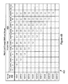
- FIG. 4B illustrates an example of a data structure 450 that may be used to provide the values n and m used by circuit 400 for the subtraction from the maximum frame length, as described above. These values are calculated such that cut-through routing can be implemented even though there may be a disparity between receive and transmit link rates.
- Data structure 450 may include a column 452 for storing the link rate for the receive side, for example, the link rate for links 247 A- 247 D.
- a receive side sub-port may be configured to operate as 1G Ethernet port (1GE), 2G Fibre Channel port (2GFC), 4GFC, 10GE, 10GFC, 16GFC, 20GE, 20GFC, 40GE, or 40GFC.
- the transmit link rates are in row 454 .
- the transmit side links 251 A- 251 D may be configured to operate as 1GE, 2GFC, 4GFC, 10GE, 10GFC, 16GFC, 20GE, 20GFC, 40GE, or 40GFC.
- the n and m values depend on the receive side and transmit side link rates. For example, when 1GE receives frames and a 2GFC is the transmit link, then n is equal to 1 and m is equal to 4. When a receive port is operating as 2GFC and the transmit port is operating at 10GE, then n is equal to 3 and m is equal to 5.
- the n and m values are chosen to reduce errors between the estimated cut-through threshold value calculated by circuit 400 and the true data packet rate ratio between the receive and transmit links.
- the n and m values are chosen so as not to allow the estimated cut-through threshold to be less than the actual data rate ratio.
- the n and m values could be generated using a computer algorithm, details of which are not germane to the embodiments disclosed herein.
- Data structure 450 only needs to be computed once for the supported link rates.
- the n and m values are used for inputs 404 , 406 , as described above with respect to FIG. 4A .
- FIG. 4C illustrates a process 460 , according to one embodiment.
- the process begins in block B 462 , when a start of a frame (or data packet) is received at a sub-port of base-port 128 .
- the packet's destination port is first determined by the routing sequencer 232 .
- the transmit rate of the destination port is looked up from the transmit rate data structure 233 .
- an estimate of the cut-through threshold value is determined using the circuit 400 , described above in detail.
- the rate for the port receiving the packet is looked up from the configuration information stored at the common segment 236 .
- the word count maintained at the receive port is increased to reflect the packet data words that have been received.
- the port determines if the end of the frame (or packet) has been received. If yes, the process moves to block B 484 , otherwise in block B 476 , the process determines if cut-through routing has been disabled. If yes, then the process moves back to block B 472 . If not, then in block B 478 , the process determines if the transmit rate code is equal to a code for “store and forward” routing, i.e., receiving the entire frame and then routing. If the answer is yes, then the process moves back to block B 472 . If not, then in block B 480 , the process determines if the receive rate is greater than the transmit rate. If yes, then the process moves to block B 484 , described below. If the receive rate is less than the transmit rate, then in block B 482 , the process determines if the word count has reached the estimate of the cut-through threshold value. If not, the process moves back to block B 472 .
- block B 482 If the answer to the query in block B 482 is yes, then the process moves to block B 484 . Furthermore, if the answer is yes in block B 474 , the process moves to block B 484 . In block B 484 , the process determines that the cut condition has been met and the process then ends in block B 486 .
- FIG. 5 illustrates a process 500 for determining the n and m values, according to one embodiment.
- the process begins in block B 502 , when the actual data packet transfer rate is determined for all supported link rates.
- the first support receive link rate 452 is selected.
- a transmit rate that is the next highest than the selected receive link rate is selected.
- the ratio of the receive data packet transfer rate and the transmit data transfer packet rate is determined, for example, by using long division.
- n and m values are selected to provide an estimated cut-through threshold value that is closest to the calculated ratio.
- block B 512 the process determines if all transmit link rates are greater than the selected receive link rate that was processed by the blocks described above. If not, then the next transmit link rate is selected in block B 514 and the process moves to block B 508 . If the transmit link rate is greater than the receive link rate, in block B 512 , then in block B 516 the process determines if all the receive link rates have been processed. If not, then the process moves to block B 518 where the next receive link rate is selected and the process moves to block B 506 . If all link rates have been processed, in block B 516 , then the process ends in block B 520 .
Abstract
Description
Claims (15)
Priority Applications (1)
| Application Number | Priority Date | Filing Date | Title |
|---|---|---|---|
| US13/678,086 US9444713B1 (en) | 2012-11-15 | 2012-11-15 | Cut-through routing for network devices |
Applications Claiming Priority (1)
| Application Number | Priority Date | Filing Date | Title |
|---|---|---|---|
| US13/678,086 US9444713B1 (en) | 2012-11-15 | 2012-11-15 | Cut-through routing for network devices |
Publications (1)
| Publication Number | Publication Date |
|---|---|
| US9444713B1 true US9444713B1 (en) | 2016-09-13 |
Family
ID=56881480
Family Applications (1)
| Application Number | Title | Priority Date | Filing Date |
|---|---|---|---|
| US13/678,086 Active 2034-08-17 US9444713B1 (en) | 2012-11-15 | 2012-11-15 | Cut-through routing for network devices |
Country Status (1)
| Country | Link |
|---|---|
| US (1) | US9444713B1 (en) |
Cited By (1)
| Publication number | Priority date | Publication date | Assignee | Title |
|---|---|---|---|---|
| US20220377025A1 (en) * | 2019-12-06 | 2022-11-24 | Zte Corporation | Method and apparatus for processing data, device, and storage medium |
Citations (13)
| Publication number | Priority date | Publication date | Assignee | Title |
|---|---|---|---|---|
| US20020118640A1 (en) * | 2001-01-04 | 2002-08-29 | Oberman Stuart F. | Dynamic selection of lowest latency path in a network switch |
| US20020118692A1 (en) * | 2001-01-04 | 2002-08-29 | Oberman Stuart F. | Ensuring proper packet ordering in a cut-through and early-forwarding network switch |
| US20030026287A1 (en) * | 2001-07-31 | 2003-02-06 | Mullendore Rodney N. | Method and system for managing time division multiplexing (TDM) timeslots in a network switch |
| US20030026205A1 (en) * | 2001-07-31 | 2003-02-06 | Mullendore Rodney N. | Packet input thresholding for resource distribution in a network switch |
| US20030026206A1 (en) * | 2001-07-31 | 2003-02-06 | Mullendore Rodney N. | System and method for late-dropping packets in a network switch |
| US20030026267A1 (en) * | 2001-07-31 | 2003-02-06 | Oberman Stuart F. | Virtual channels in a network switch |
| US6526066B1 (en) * | 1998-07-16 | 2003-02-25 | Nortel Networks Limited | Apparatus for classifying a packet within a data stream in a computer network |
| US20030145116A1 (en) * | 2002-01-24 | 2003-07-31 | Andrew Moroney | System for communication with a storage area network |
| US20070022211A1 (en) * | 2005-07-22 | 2007-01-25 | Shinsuke Shimizu | Packet transfer system, communication network, and packet transfer method |
| US20080166046A1 (en) * | 2007-01-04 | 2008-07-10 | Dipesh Koirala | Efficient fixed-point real-time thresholding for signal processing |
| US20100092174A1 (en) * | 2008-10-13 | 2010-04-15 | Matthew Brown | Differential Inverse Multiplexing Virtual Channels in 40G Ethernet Applications |
| US20120063333A1 (en) * | 2010-09-14 | 2012-03-15 | Brocade Communications Systems, Inc. | Manageability Tools for Lossless Networks |
| US20130286845A1 (en) * | 2012-04-30 | 2013-10-31 | Fujitsu Limited | Transmission rate control |
-
2012
- 2012-11-15 US US13/678,086 patent/US9444713B1/en active Active
Patent Citations (13)
| Publication number | Priority date | Publication date | Assignee | Title |
|---|---|---|---|---|
| US6526066B1 (en) * | 1998-07-16 | 2003-02-25 | Nortel Networks Limited | Apparatus for classifying a packet within a data stream in a computer network |
| US20020118640A1 (en) * | 2001-01-04 | 2002-08-29 | Oberman Stuart F. | Dynamic selection of lowest latency path in a network switch |
| US20020118692A1 (en) * | 2001-01-04 | 2002-08-29 | Oberman Stuart F. | Ensuring proper packet ordering in a cut-through and early-forwarding network switch |
| US20030026205A1 (en) * | 2001-07-31 | 2003-02-06 | Mullendore Rodney N. | Packet input thresholding for resource distribution in a network switch |
| US20030026206A1 (en) * | 2001-07-31 | 2003-02-06 | Mullendore Rodney N. | System and method for late-dropping packets in a network switch |
| US20030026267A1 (en) * | 2001-07-31 | 2003-02-06 | Oberman Stuart F. | Virtual channels in a network switch |
| US20030026287A1 (en) * | 2001-07-31 | 2003-02-06 | Mullendore Rodney N. | Method and system for managing time division multiplexing (TDM) timeslots in a network switch |
| US20030145116A1 (en) * | 2002-01-24 | 2003-07-31 | Andrew Moroney | System for communication with a storage area network |
| US20070022211A1 (en) * | 2005-07-22 | 2007-01-25 | Shinsuke Shimizu | Packet transfer system, communication network, and packet transfer method |
| US20080166046A1 (en) * | 2007-01-04 | 2008-07-10 | Dipesh Koirala | Efficient fixed-point real-time thresholding for signal processing |
| US20100092174A1 (en) * | 2008-10-13 | 2010-04-15 | Matthew Brown | Differential Inverse Multiplexing Virtual Channels in 40G Ethernet Applications |
| US20120063333A1 (en) * | 2010-09-14 | 2012-03-15 | Brocade Communications Systems, Inc. | Manageability Tools for Lossless Networks |
| US20130286845A1 (en) * | 2012-04-30 | 2013-10-31 | Fujitsu Limited | Transmission rate control |
Cited By (2)
| Publication number | Priority date | Publication date | Assignee | Title |
|---|---|---|---|---|
| US20220377025A1 (en) * | 2019-12-06 | 2022-11-24 | Zte Corporation | Method and apparatus for processing data, device, and storage medium |
| US11818057B2 (en) * | 2019-12-06 | 2023-11-14 | Xi'an Zhongxing New Software Co. Ltd. | Method and apparatus for processing data, device, and storage medium |
Similar Documents
| Publication | Publication Date | Title |
|---|---|---|
| US9172602B1 (en) | Method and system for auto-negotiation | |
| US9172655B1 (en) | Systems and methods for quality of service in networks | |
| US8068482B2 (en) | Method and system for network switch element | |
| US7512067B2 (en) | Method and system for congestion control based on optimum bandwidth allocation in a fibre channel switch | |
| US7894348B2 (en) | Method and system for congestion control in a fibre channel switch | |
| US9369298B2 (en) | Directed route load/store packets for distributed switch initialization | |
| US9118586B2 (en) | Multi-speed cut through operation in fibre channel switches | |
| US11637773B2 (en) | Scaled-out transport as connection proxy for device-to-device communications | |
| US9935779B1 (en) | Methods and apparatus for using virtual local area networks in a switch fabric | |
| US7522529B2 (en) | Method and system for detecting congestion and over subscription in a fibre channel network | |
| US8995457B1 (en) | Systems and methods for modifying frames in a network device | |
| US9282000B1 (en) | Network devices having configurable receive packet queues and related methods | |
| US9264383B1 (en) | Systems and methods for quality of service for link aggregation groups | |
| US9411400B1 (en) | Methods and systems for advertsing available credit at memory of network device ports based on temperature | |
| US8976667B1 (en) | Method and system for programmable delay before transmission pausing | |
| US9154455B1 (en) | Method and system for determining drop eligibility of network information | |
| US9282046B1 (en) | Smoothing FIFO and methods thereof | |
| US9444713B1 (en) | Cut-through routing for network devices | |
| US9225672B1 (en) | Systems and methods for packet grouping in networks | |
| US8995455B1 (en) | Memory devices for network devices and associated methods | |
| US9256491B1 (en) | Method and system for data integrity | |
| US9172661B1 (en) | Method and system for using lane alignment markers | |
| US9281953B1 (en) | Systems and methods for routing multicast packets | |
| US9225808B1 (en) | Systems and methods for processing information by a network device | |
| US9590924B1 (en) | Network device scheduler and methods thereof |
Legal Events
| Date | Code | Title | Description |
|---|---|---|---|
| AS | Assignment |
Owner name: QLOGIC, CORPORATION, CALIFORNIA Free format text: ASSIGNMENT OF ASSIGNORS INTEREST;ASSIGNORS:DROPPS, FRANK R.;VERBA, CRAIG M.;SIGNING DATES FROM 20121010 TO 20121011;REEL/FRAME:029305/0754 |
|
| STCF | Information on status: patent grant |
Free format text: PATENTED CASE |
|
| CC | Certificate of correction | ||
| AS | Assignment |
Owner name: JPMORGAN CHASE BANK, N.A., AS COLLATERAL AGENT, IL Free format text: SECURITY AGREEMENT;ASSIGNOR:QLOGIC CORPORATION;REEL/FRAME:041854/0119 Effective date: 20170228 |
|
| AS | Assignment |
Owner name: CAVIUM, INC., CALIFORNIA Free format text: MERGER;ASSIGNOR:QLOGIC CORPORATION;REEL/FRAME:044812/0504 Effective date: 20160615 |
|
| AS | Assignment |
Owner name: CAVIUM NETWORKS LLC, CALIFORNIA Free format text: RELEASE BY SECURED PARTY;ASSIGNOR:JP MORGAN CHASE BANK, N.A., AS COLLATERAL AGENT;REEL/FRAME:046496/0001 Effective date: 20180706 Owner name: CAVIUM, INC, CALIFORNIA Free format text: RELEASE BY SECURED PARTY;ASSIGNOR:JP MORGAN CHASE BANK, N.A., AS COLLATERAL AGENT;REEL/FRAME:046496/0001 Effective date: 20180706 Owner name: QLOGIC CORPORATION, CALIFORNIA Free format text: RELEASE BY SECURED PARTY;ASSIGNOR:JP MORGAN CHASE BANK, N.A., AS COLLATERAL AGENT;REEL/FRAME:046496/0001 Effective date: 20180706 |
|
| AS | Assignment |
Owner name: CAVIUM, LLC, CALIFORNIA Free format text: CHANGE OF NAME;ASSIGNOR:CAVIUM, INC.;REEL/FRAME:047205/0953 Effective date: 20180921 |
|
| AS | Assignment |
Owner name: CAVIUM INTERNATIONAL, CAYMAN ISLANDS Free format text: ASSIGNMENT OF ASSIGNORS INTEREST;ASSIGNOR:CAVIUM, LLC;REEL/FRAME:051948/0807 Effective date: 20191231 |
|
| MAFP | Maintenance fee payment |
Free format text: PAYMENT OF MAINTENANCE FEE, 4TH YEAR, LARGE ENTITY (ORIGINAL EVENT CODE: M1551); ENTITY STATUS OF PATENT OWNER: LARGE ENTITY Year of fee payment: 4 |
|
| AS | Assignment |
Owner name: MARVELL ASIA PTE, LTD., SINGAPORE Free format text: ASSIGNMENT OF ASSIGNORS INTEREST;ASSIGNOR:CAVIUM INTERNATIONAL;REEL/FRAME:053179/0320 Effective date: 20191231 |
|
| MAFP | Maintenance fee payment |
Free format text: PAYMENT OF MAINTENANCE FEE, 8TH YEAR, LARGE ENTITY (ORIGINAL EVENT CODE: M1552); ENTITY STATUS OF PATENT OWNER: LARGE ENTITY Year of fee payment: 8 |