US9438891B2 - Holocam systems and methods - Google Patents
Holocam systems and methods Download PDFInfo
- Publication number
- US9438891B2 US9438891B2 US14/208,368 US201414208368A US9438891B2 US 9438891 B2 US9438891 B2 US 9438891B2 US 201414208368 A US201414208368 A US 201414208368A US 9438891 B2 US9438891 B2 US 9438891B2
- Authority
- US
- United States
- Prior art keywords
- scene
- values
- points
- depth
- data
- Prior art date
- Legal status (The legal status is an assumption and is not a legal conclusion. Google has not performed a legal analysis and makes no representation as to the accuracy of the status listed.)
- Active, expires
Links
- 238000000034 method Methods 0.000 title claims abstract description 73
- 239000000872 buffer Substances 0.000 claims description 45
- 230000009466 transformation Effects 0.000 claims description 34
- 238000013519 translation Methods 0.000 claims description 25
- 239000011159 matrix material Substances 0.000 claims description 21
- 238000000844 transformation Methods 0.000 claims description 14
- 238000011156 evaluation Methods 0.000 claims description 9
- 230000011218 segmentation Effects 0.000 claims description 7
- 238000001914 filtration Methods 0.000 claims description 6
- 238000009877 rendering Methods 0.000 claims description 6
- 230000002776 aggregation Effects 0.000 claims description 4
- 238000004220 aggregation Methods 0.000 claims description 4
- 230000005540 biological transmission Effects 0.000 claims description 4
- 230000007246 mechanism Effects 0.000 abstract description 2
- 239000002131 composite material Substances 0.000 abstract 1
- 230000008569 process Effects 0.000 description 17
- 238000005259 measurement Methods 0.000 description 11
- 238000013459 approach Methods 0.000 description 10
- 230000006870 function Effects 0.000 description 6
- 239000013598 vector Substances 0.000 description 6
- 238000012545 processing Methods 0.000 description 5
- 238000004364 calculation method Methods 0.000 description 3
- 238000004891 communication Methods 0.000 description 3
- 238000001514 detection method Methods 0.000 description 3
- 101100406515 Drosophila melanogaster orb2 gene Proteins 0.000 description 2
- 101100258025 Schizosaccharomyces pombe (strain 972 / ATCC 24843) shk1 gene Proteins 0.000 description 2
- 238000000354 decomposition reaction Methods 0.000 description 2
- 238000010586 diagram Methods 0.000 description 2
- 238000002474 experimental method Methods 0.000 description 2
- 238000013178 mathematical model Methods 0.000 description 2
- 238000012986 modification Methods 0.000 description 2
- 230000004048 modification Effects 0.000 description 2
- 238000012544 monitoring process Methods 0.000 description 2
- 230000003287 optical effect Effects 0.000 description 2
- 230000009467 reduction Effects 0.000 description 2
- 230000003068 static effect Effects 0.000 description 2
- 230000000007 visual effect Effects 0.000 description 2
- 238000012935 Averaging Methods 0.000 description 1
- 108010001267 Protein Subunits Proteins 0.000 description 1
- 238000003491 array Methods 0.000 description 1
- 230000002146 bilateral effect Effects 0.000 description 1
- 238000006243 chemical reaction Methods 0.000 description 1
- 230000000694 effects Effects 0.000 description 1
- 230000008713 feedback mechanism Effects 0.000 description 1
- 230000006872 improvement Effects 0.000 description 1
- 238000013507 mapping Methods 0.000 description 1
- 239000003550 marker Substances 0.000 description 1
- 230000002093 peripheral effect Effects 0.000 description 1
- 230000005855 radiation Effects 0.000 description 1
- 238000000926 separation method Methods 0.000 description 1
- 230000002123 temporal effect Effects 0.000 description 1
- 239000010409 thin film Substances 0.000 description 1
- 238000012546 transfer Methods 0.000 description 1
Images


Classifications
-
- H04N13/0275—
-
- H—ELECTRICITY
- H04—ELECTRIC COMMUNICATION TECHNIQUE
- H04N—PICTORIAL COMMUNICATION, e.g. TELEVISION
- H04N13/00—Stereoscopic video systems; Multi-view video systems; Details thereof
- H04N13/20—Image signal generators
- H04N13/275—Image signal generators from 3D object models, e.g. computer-generated stereoscopic image signals
-
- G—PHYSICS
- G06—COMPUTING; CALCULATING OR COUNTING
- G06T—IMAGE DATA PROCESSING OR GENERATION, IN GENERAL
- G06T17/00—Three dimensional [3D] modelling, e.g. data description of 3D objects
-
- G—PHYSICS
- G06—COMPUTING; CALCULATING OR COUNTING
- G06T—IMAGE DATA PROCESSING OR GENERATION, IN GENERAL
- G06T2210/00—Indexing scheme for image generation or computer graphics
- G06T2210/56—Particle system, point based geometry or rendering
-
- H—ELECTRICITY
- H04—ELECTRIC COMMUNICATION TECHNIQUE
- H04N—PICTORIAL COMMUNICATION, e.g. TELEVISION
- H04N2213/00—Details of stereoscopic systems
- H04N2213/003—Aspects relating to the "2D+depth" image format
Definitions
- the present patent document is directed towards systems and methods for capturing a scene, displaying a scene, or both. More particularly, the present patent document is directed towards systems and methods for capturing a scene using video or still images and generating a three-dimensional representation of the scene, which may then be displayed from different viewing angles.
- a conventional image capture device such as a camera
- the viewpoint is fixed to a particular point in the space.
- conventional cameras do not allow for changing the viewpoint after the picture or the video has been taken.
- This fixed viewpoint is due, in part, to the type of data acquired by these cameras.
- traditional cameras acquire a matrix of color components of a scene.
- Another contributing factor is that conventional cameras capture the scene from one, and only one, vantage point. That is, the matrix of color component represents the scene as it appears from the vantage point of the camera. Because the camera only has a representation from a single vantage point, a viewer is limited to that view.
- FIG. 1 displays a holocam system from an input/output perspective according to embodiments of the present invention.
- FIG. 2 depicts a holocam system and process flow according to embodiments of the present invention.
- FIG. 3 depicts a method for generating a three-dimensional model of a scene that can be used for free viewpoint displaying according to embodiment of the present invention.
- FIGS. 4A and 4B present automatic scene registration according to embodiments of the present invention.
- FIG. 5 depicts an example of a point cloud in which a number of planar surfaces have been identified and a floor plane has been identified according to embodiments of the present invention.
- FIG. 6 graphically depicts an example of voxel segmentation of the point cloud depicted in FIG. 5 according to embodiments of the present invention.
- FIG. 7 illustrates examples potential guidelines that may be used to identify potential rotations between vantage points according to embodiments of the present invention.
- FIGS. 8 and 9 present aspects of user-assisted scene registration according to embodiments of the present invention.
- FIG. 10 depicts the side and front views of a point acquisition device according to embodiments of the present invention.
- FIG. 11 shows an example of a Connectivity Graph according to embodiments of the present invention.
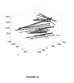
- FIG. 12 depicts matching pairs of points between orbs before the scene registration procedure according to embodiments of the present invention.
- FIG. 13 depicts matching pairs of points between orbs after the scene registration procedure according to embodiments of the present invention.
- FIG. 14 depict a methodology for performing a reprojection according to embodiments of the present invention.
- FIG. 15 depicts sample results of reprojection according to embodiments of the present invention.
- FIG. 16 depict a projective Iterative Closest Point (ICP) approach according to embodiments of the present invention.
- ICP Iterative Closest Point
- FIG. 17 shows a sample result following projective ICP according to embodiments of the present invention.
- FIG. 18 provides a table summary of numerical results of the example in FIG. 17 according to embodiments of the present invention.
- FIG. 19 presents the utilization as the projective ICP algorithm progressed towards convergence of the example in FIG. 17 according to embodiments of the present invention.
- FIG. 20 shows the delta values as the projective ICP algorithm progressed towards convergence of the example in FIG. 17 according to embodiments of the present invention.
- FIG. 21 depicts a method for performing projective bundle ICP according to embodiments of the present invention.
- FIG. 22 shows a sample result of projective bundle ICP according to embodiments of the present invention.
- FIG. 23 depicts a block diagram illustrating an exemplary computing system which may be used to implement aspects of the present invention.
- connections between components within the figures are not intended to be limited to direct connections. Rather, data between these components may be modified, re-formatted, or otherwise changed by intermediary components. Also, additional or fewer connections may be used. It shall also be noted that the terms “coupled” or “communicatively coupled” shall be understood to include direct connections, indirect connections through one or more intermediary devices, and wireless connections.
- references in the specification to “one embodiment,” “preferred embodiment,” “an embodiment,” or “embodiments” means that a particular feature, structure, characteristic, or function described in connection with the embodiment is included in at least one embodiment of the invention and may be in more than one embodiment. Also, such phrases in various places in the specification are not necessarily all referring to the same embodiment or embodiments. It shall be noted that the use of the terms “set” and “group” in this patent document shall include any number of elements. While the terms depth (distance from a plane), distance (radial distance from a sensor), and range may have slightly different meanings, these terms may be used interchangeable herein.
- TOF sensors have limited range and may not work under certain conditions, such as, exposure to very bright sunlight.
- depth sensors have a limited field of view (FOV) and generally operate under line-of-sight assumptions. Therefore, the combination of the data acquired using a number of sensors (or a sensor at a number of locations) is a major requirement for being able to reconstruct the three-dimensional (3D) content of a scene, as opposed to acquiring the range profile of the scene from one vantage point.
- FOV field of view
- Acquisition of the depth data is, in fact, the producer of content for a larger system which has to have appropriate means for transferring the acquired data and presenting it for the consumer side. This requires proper encoding of the multiplicity of range information acquired of the scene in combination with the corresponding visible images.
- the encoded data should be transmitted in a fashion possible on conventional communication lines and then presented on a display system as directed by a user.
- a “holocam” system represents novel systems and novel methodologies that allow for capturing visual characteristics of a scene and for allowing a user to select arbitrary viewpoints based upon a generated model of the scene.
- the various embodiments enable the combination of range information and visible images acquired using different devices.
- these pieces of range information can be, and are encouraged to have been, captured using devices which utilize different depth data acquisition methods.
- holocam systems combine these data sources into single models of the scene and are capable of transmitting the data through a network to reach a display device.
- embodiments of holocam systems can combine depth information and visible images acquired using different methods and from a number of different vantage points into a model created from the scene. And, embodiments of holocam systems can transfer a model created from the scene through a conventional network and provide the information needed for displaying the content from any perspective on a display system.
- a holocam system is a content-creation system, which enables the real-time capture and streaming of real-world scenes.
- FIG. 1 displays a holocam system from an input/output perspective according to embodiments of the present invention.
- the holocam system 105 receives input from one or more input devices 110 - x .
- an input device may comprise an image capture device, such as a video or still image camera, combined with a depth measuring input device, such as a time of flight (TOF), structured light, lightfield, stereo sensors, or other depth measuring devices.
- TOF time of flight
- the combined image and depth measuring devices may be referred herein as an “orb.”
- the holocam system 105 may receive input from the same orb located at different positions or from different orbs located at different positions. In any event, the holocam system 105 receives input data of a scene from a plurality of positions.
- the image color information (which shall be understood to include black and white as well as other color image information such as red, green, and blue (RGB)) as well as the depth information (D) are supplied to the holocam system 105 .
- the holocam system takes the input data of the scene and generates a three-dimensional model.
- This model may be transmitted to one or more rendering devices 115 - x that use the model data to render a view for display by a display device 120 - x .
- the holocam system may comprise an acquisition module 225 that receives scene information 210 (e.g., visible image data and depth data (RGBD)) at different vantage points through utilizing one or more depth data acquisition devices and one or more visible image acquisition devices.
- scene information 210 e.g., visible image data and depth data (RGBD)
- RGBD depth data
- the runtime processor filters the depth data, which tends to be rather noisy, according to one or more filtering operations.
- filtering operations include, but are not limited to, anisotropic filters, bilateral filters, temporal averaging, and outlier removal; such filtering operations are well-known to those of ordinary skill in the art.
- some or all of the filtering operations may be performed by the image/depth acquisition devices, the acquisition module, or both.
- a holocam system may be configured to combine RGBD data through cross-correlating range data and visible image data to provide values for missing areas and verify segments which are captured in more than one source.
- a holocam system may perform resolution enhancement through joint processing of different data items at different resolutions.
- a holocam system comprises a model creation module 245 that produces, for a vantage point, a three-dimensional (3D) model by combining depth data and visible image data from that vantage point.
- one of the representations utilized by a holocam system is a textured triangle mesh.
- the model creation module 245 also defines a source-independent canonical space which is used to register all vantage points into that space.
- a holocam system also comprises a scene registration module 230 that performs scene registration to acquire geometric transformations for merging two or more 3D models of the scene from different vantage points into the source-independent canonical space.
- the scene registration module 230 may also receive system layout information 215 , which may include information about the physical layout of the system (e.g., horizontal axes of the depth devices are parallel or substantially parallel to the ground, locations of orbs in the scene, rigid body transforms between the orbs, etc.).
- system layout information 215 may include information about the physical layout of the system (e.g., horizontal axes of the depth devices are parallel or substantially parallel to the ground, locations of orbs in the scene, rigid body transforms between the orbs, etc.).
- a holocam system may also comprise an audio module 235 that receives audio data 220 about the scene from one or more audio input devices.
- a holocam system 205 may include a transmission module 250 which encodes a scene model into a data stream for transmission over a network.
- a model may be received by a rendering module 260 that receives as an input the scene model and a desired view angle 255 and renders a view 265 of the scene for that view angle 255 for display by one or more display devices.
- the rendering module 260 may be separate from a holocam system 205 , part of a holocam system 205 , or both.
- FIG. 3 depicted is a method for generating a three-dimensional model of a scene that can be used for free viewpoint displaying according to embodiment of the present invention.
- the method of FIG. 3 may be performed by a holocam system, such as the one depicted in FIG. 2 .
- the method commences by a holocam system receiving ( 305 ) visual image/color data (e.g., RGB, grayscale, etc.) and depth (D) data of a scene from a plurality of vantage points.
- visual image/color data e.g., RGB, grayscale, etc.
- depth (D) data of a scene from a plurality of vantage points.
- color and depth information of the scene from the plurality of vantage points may be received from orbs at each of the plurality of vantage points or from one orb moved to different vantage points, although for generating a model for free viewpoint video rather than a still image, multiple orbs is preferred.
- the holocam system may perform ( 310 ) one or more filtering operations on the depth data to make the data less noisy.
- the holocam system produces ( 315 ), for each vantage point, a three-dimensional (3D) model of data by combining the depth data information and visible image data.
- the holocam defines ( 320 ) a source-independent canonical space which is used to register two or more of the 3D models into that space.
- scene registration is performed ( 325 ) to acquire the geometrical transformations which can be used to merge multiple 3D models of the same scene from their corresponding different vantage points into a unique one.
- the scene registration may be automatically performed, may be user assisted, or may be a combination thereof.
- FIGS. 4A and 4B present automatic scene registration according to embodiments of the present invention.
- FIGS. 8 and 9 present aspects of user-assisted scene registration according to embodiments of the present invention.
- the holocam system may perform ( 330 ) scene reregistration.
- scene reregistration may be performed to improve the transformation into the canonical space, to compensate for movement of one or more orbs, or both.
- FIGS. 4A and 4B depict automatic scene registration according to embodiments of the present invention.
- the method commences by performing ( 405 ) point cloud generation for data from an input orb.
- the intrinsic camera parameters e.g., camera center and focal length values (c x , c y , f x , and f y ) and distortion coefficients (k1, k2, k3, p1, and p2)
- the depth measurements i, j, depth
- the points in the sensor plane can be converted to real world coordinates (X, Y, Z). Converting between sensor values and real world coordinates to form a point cloud is well known to those of ordinary skill in the art.
- the next step involves detecting ( 410 ) planar surfaces in the point cloud.
- Plane detecting may be performed according to the following methodology.
- tiles e.g., 10 pixels ⁇ 10 pixels
- the tiles may be formed by starting in one portion and moving systematically through all the points.
- adjacent tiles may overlap by a set percentage (e.g., 80% overlap) or a set number of pixels (e.g., 2 pixel separation between tiles when generating tiles).
- FIG. 5 depicts an example of a point cloud 505 in which a number of planar surfaces have been identified (e.g., wall elements 510 , 515 , and 520 ) and a floor plane (e.g., floor 525 ) has been identified.
- a number of planar surfaces have been identified (e.g., wall elements 510 , 515 , and 520 ) and a floor plane (e.g., floor 525 ) has been identified.
- the floor plane comprises a large number of points and of the identified planes requires the least rotation to conform to an expected floor orientation.
- voxel segmentation is performed ( 425 ) by projecting contents in the scene to the floor plane.
- FIG. 6 graphically depicts an example of voxel segmentation, according to embodiments of the present invention, of the point cloud depicted in FIG. 5 . Note that several voxels (e.g., 605 , 610 , 615 , etc.) have been formed.
- the next step is to identify ( 430 ) intersections of potential wall planes with the floor plane. These intersections may be used as guidelines to provide rotation estimates between vantage points.
- FIG. 7 illustrates examples of potential guidelines (e.g., 705 - 740 ) that may be used (according to embodiments of the present invention) to identify potential rotations between vantage points.
- guideline 705 in vantage point 2 may be found to correspond to guideline 710 in vantage point 1 .
- intersections identified in the prior section may be used as guidelines to provide ( 435 ) rotation estimates between vantage points.
- all of the intersections may be used to estimate rotations between vantage points.
- a set of the top most common or most voted-for candidate rotation between two vantage points may be selected.
- a 0-2 ⁇ interval may be divided into 16 bins to facilitate the voting, although one skilled in the art shall recognize that any of a number of voting mechanisms may be used.
- the top 16 in-plane rotation estimate may be selected.
- the voxel map for a vantage point is rotated ( 440 ) according to a rotation estimate and an in-plane two-dimensional (2D) translation is estimated by comparing sliding 2D maps.
- the in-plane 2D translation estimates may be obtained exhaustively. This process may be repeated for all of the top in-plane rotation estimates.
- the in-plane rotation and in-plane 2D translation combination with the smallest combined error may be selected.
- an in-plane rotation estimate, and an in-plane translation estimate may be combined into a transformation matrix (e.g., a 4 ⁇ 4 transformation matrix).
- embodiments of the present invention may include or alternatively use a user-assisted registration.
- Embodiments of user-assisted scene registration utilize a point acquisition device (such as, by way of example and not limitation, a Near Infra-Red (NIR) point marker) to capture 3D points by a number of orbs from different vantage points. The measurements are utilized to create scene registration information.
- the registration may also include utilizing a Bundle Adjustment methodology, which is described in more detail below, applied on points obtained using a point acquisition device.
- each orb produces a depth map and a Near Infra-Red (NIR) map.
- NIR Near Infra-Red
- pixels in the depth map and the NIR map are assumed to correspond, and the dimensions of the two maps are assumed to be identical, width W, height H.
- X,Y,Z it is possible to estimate a 3D representation (X,Y,Z).
- 2D coordinates will be denoted with lower case variable names
- three-dimensional (3D) coordinates will be denoted with upper case variable names.
- Homogenous and 3D vectors may be used interchangeably when the context is clear.
- the user-assisted methodologies herein address the problem of calculating O, 4 ⁇ 4 matrices, denoted as T 1 , . . . , T O .
- the input to the user-assisted methodologies herein is a set of N measurement sets.
- Each measurement set corresponds to 3D points in one orb associated with a time/frame identifier (to be addressed as “time stamp”).
- time stamp to be addressed as “time stamp”.
- the assumption is that two points with similar time stamp in the measurement sets corresponding to two orbs correspond to the same physical point.
- FIG. 8 depicts a method for user-assisted scene registration according to embodiments of the present invention.
- the method commences by generating ( 805 ) a Near Infra-Red image mask for each input device. That is, prior to monitoring a NIR image to identify points, an orb mask is created to eliminate potential problem areas. This mask identifies any pixels that receive direct IR radiation by examining the NIR image over a period of time (e.g., 100 frames). NIR points in the NIR image that do not drop to zero during the mask orb creation process are masked and only activity in other pixels trigger the point detection process.
- a Near Infra-Red image mask for each input device. That is, prior to monitoring a NIR image to identify points, an orb mask is created to eliminate potential problem areas. This mask identifies any pixels that receive direct IR radiation by examining the NIR image over a period of time (e.g., 100 frames). NIR points in the NIR image that do not drop to zero during the mask or
- FIG. 10 depicts the side and front views of a NIR device according to embodiments of the present invention.
- this device comprises a common remote control 1005 , one or more NIR emitters or light emitting diode (LED) 1010 , and one or more planar surfaces 1015 .
- the NIR emitters 1010 are provided to help the orb identify the point in space and the planar surface (which is optional) provides a larger surface from which to get a depth measurement.
- the device may have a number of emitters and may be configured in a number of directions.
- the embodiment 1000 depicted in FIG. 10 is provided by way of illustration only.
- One or more NIR signals from the device are used ( 815 ) to identify the point for each of the input images.
- the device may be held firmly at a point in the scene where at least two orbs can see the NIR pulses.
- a set time e.g. 15 seconds
- the button on the device is pressed and held for some time period (e.g., 5 seconds).
- a number of captures at the same location may be obtained. By taking a number of captures, the accuracy can be increased. Thus, for example, after the 5-second pulse, a 15-second rest period may be observed and the button may then be pressed again for 5 seconds. This process may be repeated ( 820 ) a number of time (e.g., 4 times), or until a feedback mechanism identifies that the point has been captured a set number of time (e.g., at least 4 times).
- this process may be repeated ( 825 ) with any two orbs that have overlapping capture areas in a number of different physical points in the space (e.g., 10 or more).
- FIG. 9 depicts a method for data acquisition of the points according to embodiments of the present invention.
- the data acquisition process involves monitoring of the NIR image in search of zero crossings.
- the holocam system keeps the history of a set of past frames (e.g., past 5 frames, in which the current frame is addressed as frame 0 , the previous one as frame ⁇ 1 , and so forth).
- a point which has been zero in one or more frames e.g., frame 0 and frame ⁇ 1
- this point is considered to correspond to the point acquisition device.
- a binary mask of zero pixels in one of the frames with zero values (e.g., frame 0 ) is calculated and the center of mass is calculated.
- This center of mass point may be addressed as the point (x,y), where (x,y) represents the indices of the pixel location in the depth map.
- an average depth value (e.g., mean, median, or mode) of the values in a neighborhood of the point (x,y) (e.g., 7 ⁇ 7 neighborhood) in the depth map of one of the prior non-zero frames (e.g., frame ⁇ 3 ) is then calculated ( 915 ), and may be addressed as Z.
- a planar surface e.g., surface 1015
- the LED e.g., emitter 1010
- the point device e.g., device 1000
- the emitter tells where to look in the image and the planar surface provides a neighborhood of depth values.
- the real world X and Y coordinates corresponding to the (x,y) point may be calculated as follows:
- c x , c y , f x , and f y correspond to the orb's intrinsic parameters of camera center and focal point (respectively) in the x and y directions.
- a point may be accepted only if there are at least some threshold number (e.g., 3) of other readings in the same orb within a threshold radius (e.g., within a 25 mm radius).
- measurement number n is identified using the four identities o n1 , o n2 , ⁇ right arrow over (P) ⁇ n1 , and ⁇ right arrow over (P) ⁇ n2 —that is, the same physical point has been observed by orb o n1 as ⁇ right arrow over (P) ⁇ n1 and by orb o n2 as ⁇ right arrow over (P) ⁇ n2 . It is also assumed that always o n1 ⁇ o n2 .
- the matrices T 1 , . . . , T O may be estimated by minimizing the following error function:
- T i contains 12 non-trivial elements, as shown below:
- T i [ t 0 t 1 t 2 t 3 t 4 t 5 t 6 t 7 t 8 t 9 t 10 t 11 0 0 0 1 ] .
- An operator M( ) is defined which produces a 3 ⁇ 1 vector (or equally given the 4 ⁇ 1 homogeneous representation of it),
- Z h ⁇ w is a matrix of height h and width w of zeros.
- T ⁇ [ G ⁇ ( T 1 ) ⁇ G ⁇ ( T O - 1 ) ] .
- T O is known, for example because it represents a conversion to a canonical coordinate system or that is equal to the identity matrix.
- a ij is a 3 ⁇ 12(O ⁇ 1) matrix and ⁇ right arrow over (b) ⁇ ij is a 3 ⁇ 1 vector, as defined below:
- T 1 Using the inverse of the G( ) operator on the appropriate elements of ⁇ right arrow over (T) ⁇ will produce T 1 , . . . , T O-1 (T O is already known).
- An N ⁇ O bundle matrix B may be created.
- a row n in this matrix corresponds to one instance in which the point acquisition device is visible by at least two orbs.
- each row in B has at least two ones in it.
- a Connectivity Factor of orb #o to the system may be defined as the number of instances in which orb o and at least another orb both observe the point acquisition device.
- a connection graph for the bundle may also be drawn. The strength of edge in this graph identifies the number of times and both observe the point acquisition device.
- the error range for orb o may be defined as the minimum and maximum of ⁇ T o n1 ⁇ right arrow over (P) ⁇ n1 ⁇ T o n2 ⁇ right arrow over (P) ⁇ n2 ⁇ when either o n1 or o n2 is o.
- FIG. 11 shows a Connectivity Graph for this experiment according to embodiments of the present invention.
- the Connectivity Factors corresponding to this experiment are as follows, 39.55%, 60.45%, 30.60%, and 69.40% for the four orbs.
- the thicker lines show the stronger connections between orbs.
- Orbs #1 and #4 are more strongly connected than Orbs #1 and #3.
- 402 matching points between pairs of orbs were discovered in this dataset.
- FIG. 12 depicts matching pairs of points between orbs before the scene registration procedure according to embodiments of the present invention. This figure illustrates many pairs of points connecting the pairs of orbs. For example, a point 1205 in Orb #4 has a matching point 1210 in Orb#2, thereby forming a connection 1215 between the orbs.
- FIG. 13 depicts matching pairs of points between orbs after the scene registration procedure according to embodiments of the present invention.
- T 4 is the canonical transformation.
- T 4 [ 0.58 0.38 - 0.72 2564.18 0.82 - 0.24 0.52 - 464.84 0.023 - 0.89 - 0.45 2115.29 0 0 0 1 ]
- T 1 [ - 0.37 0.48 - 0.84 2502.55 0.92 0.12 - 0.21 648.07 - 0.01 - 0.79 - 0.45 1860.74 0 0 0 1 ]
- T 2 [ 0.22 - 0.43 1.01 - 2026.65 - 0.96 - 0.13 0.20 - 2.70 - 0.02 - 0.83 - 0.30 1790.54 0 0 0 1 ]
- T 3 [ - 1.02 - 0.17 0.92 - 1557.41 - 0.78 0.14 - 0.50 1902.36 - 0.01 - 0.94 - 0.20 1831.98 0 0 0 1 ]
- Table 1 (below) lists the error values for this result.
- the min-max range for Orb #4 is 7.67-131.06 mm.
- Table 2 (below) lists the results of the direct calculation of the scene registration information for this same data.
- Embodiments of the present invention may include projective bundle iterative closest point (ICP) methodologies that take as inputs two or more organized point clouds captured by projective devices, such as time-of-flight sensors, as well as preliminary scene registration information, and produce enhanced scene registration information.
- ICP projective bundle iterative closest point
- the applications of such methodologies are in adjusting inaccuracies in scene registration information produced by other algorithms, in updating scene registration information as one or more orb moves in space, or both.
- a subset of the projective bundle ICP approach is projective ICP, which processes two point clouds.
- An organized point cloud that satisfies this property may be captured by a projective depth measurement device (such as, by way of example and not limitation, a time-of-flight sensor, a Kinect-style device, or the like).
- Scene registration information for a number of organized point cloud P 1 , P 2 . . . , P O contains a 3 ⁇ 3 rotation matrix R o and a 3 ⁇ 1 translation matrix ⁇ right arrow over (T) ⁇ o per point cloud.
- the number of orbs may be denoted as O.
- the scene registration information is by definition a mapping between the corresponding point clouds—that is, for pairs of points ⁇ right arrow over (P) ⁇ i ⁇ P i and ⁇ right arrow over (P) ⁇ j ⁇ P j , we have: R i ⁇ right arrow over (P) ⁇ i + ⁇ right arrow over (T) ⁇ i ⁇ R j ⁇ right arrow over (P) ⁇ j + ⁇ right arrow over (T) ⁇ j
- an evaluation metric may be defined as follows:
- FIG. 14 depicts a methodology for performing a reprojection according to embodiments of the present invention.
- the methodology commences by producing ( 1405 ) a first properly-sized 2D depth (Z) buffer and filling it with an UNKNOWN identifier/value. Then, projection pixels values are calculated using an initial transform and camera intrinsic values. The projected pixel values are compared ( 1415 ) with values in the depth buffer and the depth value in the first depth buffer are set to the projected depth value responsive to the value in the first depth buffer being either UNKNOWN or larger than the projected depth value. In embodiments, steps 1410 and 1415 may performed by looping over all points in point cloud P 1 to perform the following:
- a second properly-sized 2D depth buffer (Z 2 ) is also produced ( 1420 ) and filled with an UNKNOWN identifier/value. Looping through all points in the first depth buffer (Z), if the depth value Z[i,j] is not UNKNOWN, set ( 1425 ) the corresponding point in the second depth buffer Z 2 [i,j] to that value, otherwise set ( 1425 ) it to an average (e.g., mean, median, or mode) value of a neighborhood (e.g., the eight neighbors of Z[i,j]) which are not UNKNOWN, if any exist.
- an average e.g., mean, median, or mode
- two properly-sized buffers X and Y may be calculated ( 1430 ) using values in the final depth buffer.
- the real world X and Y values may be calculated as follows:
- the X, Y, and Z values may then be combined ( 1435 ) to produce the projection points P 1 *.
- FIG. 15 depicts sample results of reprojection according to embodiments of the present invention.
- image (a) represents a first organized point cloud P 1 ;
- image (b) represents a second organized point cloud P 2 ; and
- image (c) represents P 1 *, which is P 1 reprojected into P 2 .
- UNKNOWN areas may be set to a color/gray value (see, e.g, area 1505 ).
- each point cloud has its own pair of rotation and transformation entities. Assuming that the two point clouds o 1 and o 2 are inputted into a reprojection methodology, where o 2 is to be reprojected onto o 1 , embodiments of bundle reprojection involve finding the pairwise reprojection and then following up with pair-wise reprojection.
- FIG. 16 depict a projective ICP approach according to embodiments of the present invention.
- one of the point clouds e.g., P 1
- the other point cloud e.g., P 2
- a threshold distance e.g. 200 millimeters
- R and T may be updated ( 1620 ) as follows: R ⁇ R*R ⁇ right arrow over (T) ⁇ R* ⁇ right arrow over (T) ⁇ + ⁇ right arrow over (T) ⁇ *
- the normalized number of pairs of corresponding points which are utilized in this process may be addressed as “utilization.”
- the value of the evaluation metric, ⁇ may also be calculated.
- the projective ICP algorithm may be iterated until: (1) the utilization is below a threshold level (e.g., 2%); (2) the algorithm has finished a number of iterations (e.g., 100 iterations); (3) when ⁇ is less than a threshold value (e.g., 10 millimeters); (4) if a set number of consecutive iterations (e.g., 10 iterations) produce less than a threshold level (e.g., 1 millimeter) of improvement in the value of ⁇ ; or (5) some other stop condition is reached.
- a threshold level e.g., 2%
- the algorithm has finished a number of iterations (e.g., 100 iterations)
- ⁇ e.g. 10 millimeters
- a threshold level e.g. 10 millimeter
- FIG. 17 shows a sample result following projective ICP according to embodiments of the present invention.
- the projection which includes a set of points representing a person crouching 1715 is better aligned 1720 between the point clouds 1710 following adjustment due to projective ICP.
- the table in FIG. 18 provides a summary of the numerical results of the process for the example in FIG. 17 .
- the average utilization was 47.83% and there was a 17.55% reduction in misalignment (39.46 mm reduction in misalignment on average).
- FIG. 19 and FIG. 20 show the utilization and delta values (respectively) as the projective ICP algorithm progressed towards convergence of the example in FIG. 17 . In this example, the method took 70.27 milliseconds to converge.
- the bundle projective ICP methodology extends the scope of its pair-wise counterpart to multiple point clouds.
- multiple point clouds are projected onto one point cloud, which may be addressed as the “basis” of the iteration, and, in embodiments, the problem is to find the optimal representation of the basis which minimizes the error.
- FIG. 21 depicts a method for performing projective bundle ICP according to embodiments of the present invention.
- the process commences by selecting ( 2105 ) a point cloud as a basis. Every point cloud is then reprojected ( 2110 ) onto the basis and the aggregation of the resulting points is treated as one virtual point cloud.
- the reprojection may be performed as described in Section 5.c.ii (above).
- a rigid body movement methodology such as described in Section 5.c.iii, is utilized ( 2115 ) and the rotation R* and translation T*values are obtained.
- the scene registration information may then be updated ( 2120 ), as follows, where o is any point cloud other than the basis and b is the basis: R o ⁇ R b R*R b ⁇ 1 R o ⁇ right arrow over (T) ⁇ o ⁇ R b R*R b ⁇ 1 ( ⁇ right arrow over (T) ⁇ o ⁇ right arrow over (T) ⁇ b )+ R b ⁇ right arrow over (T) ⁇ *+ ⁇ right arrow over (T) ⁇ b
- the process involves iterating ( 2125 ) through the point clouds and each time pick one point cloud as the basis, which may be selected based upon a set rotation. Thus, in each iteration, one orb is considered as the basis and the scene registration information corresponding to the other orbs are updated.
- the process ends when a stop condition has been reached.
- a stop condition may be when the amount of enhancement of the alignment in a preselected number of iterations is less than a preselected threshold, although other or additional stop conditions may be used.
- a best set of scene registration information is selected ( 2130 ).
- the evaluation metric of Section 5.b (above) may be used.
- FIG. 22 shows a sample result of projective bundle ICP according to embodiments of the present invention.
- the system includes a central processing unit (CPU) 2301 that provides computing resources and controls the computer.
- the CPU 2301 may be implemented with a microprocessor or the like, and may also include a graphics processor and/or a floating point coprocessor for mathematical computations.
- the system 2300 may also include system memory 2302 , which may be in the form of random-access memory (RAM) and read-only memory (ROM).
- An input controller 2303 represents an interface to various input device(s) 2304 , such as a keyboard, mouse, or stylus.
- the system 2300 may also include a storage controller 2307 for interfacing with one or more storage devices 2308 each of which includes a storage medium such as magnetic tape or disk, or an optical medium that might be used to record programs of instructions for operating systems, utilities and applications which may include embodiments of programs that implement various aspects of the present invention.
- Storage device(s) 2308 may also be used to store processed data or data to be processed in accordance with the invention.
- the system 2300 may also include a display controller 2309 for providing an interface to a display device 2311 , which may be a cathode ray tube (CRT), a thin film transistor (TFT) display, or other type of display.
- the system 2300 may also include a printer controller 2312 for communicating with a printer 2313 .
- a communications controller 2314 may interface with one or more communication devices 2315 , which enables the system 2300 to connect to remote devices through any of a variety of networks including the Internet, a local area network (LAN), a wide area network (WAN), or through any suitable electromagnetic carrier signals including infrared signals.
- bus 2316 which may represent more than one physical bus.
- various system components may or may not be in physical proximity to one another.
- input data and/or output data may be remotely transmitted from one physical location to another.
- programs that implement various aspects of this invention may be accessed from a remote location (e.g., a server) over a network.
- Such data and/or programs may be conveyed through any of a variety of machine-readable medium including magnetic tape or disk or optical disc, or a transmitter, receiver pair.
- Embodiments of the present invention may be encoded upon one or more non-transitory computer-readable media with instructions for one or more processors or processing units to cause steps to be performed.
- the one or more non-transitory computer-readable media shall include volatile and non-volatile memory.
- alternative implementations are possible, including a hardware implementation or a software/hardware implementation.
- Hardware-implemented functions may be realized using ASIC(s), programmable arrays, digital signal processing circuitry, or the like.
Abstract
Description
Er=∥T i {right arrow over (P)} i −T j {right arrow over (P)} j∥.
E=└Z 3×12(o-1) MZ 3×12(O-o-1)┘.
T o
∥T o
| TABLE 1 | |||||
| ORB1 | ORB2 | Min Error | Max | Median Error | |
| 1 | 2 | — | — | — | |
| 1 | 3 | 16.50 mm | 57.50 mm | 26.75 |
|
| 1 | 4 | 7.67 mm | 48.98 mm | 23.43 |
|
| 2 | 3 | 6.14 mm | 61.69 mm | 18.42 |
|
| 2 | 4 | 8.52 mm | 131.06 mm | 54.08 |
|
| 3 | 4 | — | — | — | |
| TABLE 2 | |||||
| ORB1 | ORB2 | Min Error | Max | Median Error | |
| 1 | 2 | — | — | — | |
| 1 | 3 | 204.89 mm | 296.02 mm | 205.98 |
|
| 1 | 4 | 15.71 mm | 61.42 mm | 35.99 |
|
| 2 | 3 | 12.75 mm | 80.20 mm | 39.16 |
|
| 2 | 4 | 17.57 mm | 148.10 mm | 55.97 |
|
| 3 | 4 | — | — | — | |
R i {right arrow over (P)} i +{right arrow over (T)} i ≈R j {right arrow over (P)} j +{right arrow over (T)} j
and
where Z[i,j] is the final depth buffer (i.e., the second depth buffer).
R=R O
{right arrow over (T)}=R o
R←R*R
{right arrow over (T)}←R*{right arrow over (T)}+{right arrow over (T)}*
R o ←R b R*R b −1 R o
{right arrow over (T)} o ←R b R*R b −1({right arrow over (T)} o −{right arrow over (T)} b)+R b {right arrow over (T)}*+{right arrow over (T)} b
Claims (20)
Priority Applications (2)
| Application Number | Priority Date | Filing Date | Title |
|---|---|---|---|
| US14/208,368 US9438891B2 (en) | 2014-03-13 | 2014-03-13 | Holocam systems and methods |
| JP2015005473A JP6485053B2 (en) | 2014-03-13 | 2015-01-15 | System, method and program for generating a three-dimensional model |
Applications Claiming Priority (1)
| Application Number | Priority Date | Filing Date | Title |
|---|---|---|---|
| US14/208,368 US9438891B2 (en) | 2014-03-13 | 2014-03-13 | Holocam systems and methods |
Publications (2)
| Publication Number | Publication Date |
|---|---|
| US20150261184A1 US20150261184A1 (en) | 2015-09-17 |
| US9438891B2 true US9438891B2 (en) | 2016-09-06 |
Family
ID=54068778
Family Applications (1)
| Application Number | Title | Priority Date | Filing Date |
|---|---|---|---|
| US14/208,368 Active 2035-01-13 US9438891B2 (en) | 2014-03-13 | 2014-03-13 | Holocam systems and methods |
Country Status (2)
| Country | Link |
|---|---|
| US (1) | US9438891B2 (en) |
| JP (1) | JP6485053B2 (en) |
Cited By (8)
| Publication number | Priority date | Publication date | Assignee | Title |
|---|---|---|---|---|
| US20170227353A1 (en) * | 2016-02-08 | 2017-08-10 | YouSpace, Inc | Floor estimation for human computer interfaces |
| US20170243352A1 (en) | 2016-02-18 | 2017-08-24 | Intel Corporation | 3-dimensional scene analysis for augmented reality operations |
| US10437342B2 (en) | 2016-12-05 | 2019-10-08 | Youspace, Inc. | Calibration systems and methods for depth-based interfaces with disparate fields of view |
| US10482681B2 (en) | 2016-02-09 | 2019-11-19 | Intel Corporation | Recognition-based object segmentation of a 3-dimensional image |
| US10573018B2 (en) * | 2016-07-13 | 2020-02-25 | Intel Corporation | Three dimensional scene reconstruction based on contextual analysis |
| US10701344B2 (en) | 2015-12-02 | 2020-06-30 | Seiko Epson Corporation | Information processing device, information processing system, control method of an information processing device, and parameter setting method |
| US10740986B2 (en) | 2018-08-30 | 2020-08-11 | Qualcomm Incorporated | Systems and methods for reconstructing a moving three-dimensional object |
| US11769275B2 (en) | 2017-10-19 | 2023-09-26 | Interdigital Vc Holdings, Inc. | Method and device for predictive encoding/decoding of a point cloud |
Families Citing this family (15)
| Publication number | Priority date | Publication date | Assignee | Title |
|---|---|---|---|---|
| GB201407643D0 (en) * | 2014-04-30 | 2014-06-11 | Tomtom Global Content Bv | Improved positioning relatie to a digital map for assisted and automated driving operations |
| DE112014006911T5 (en) * | 2014-08-29 | 2017-05-11 | Technische Universität München | Method and system for scanning an object using an RGB-D sensor |
| WO2016079960A1 (en) * | 2014-11-18 | 2016-05-26 | Seiko Epson Corporation | Image processing apparatus, control method for image processing apparatus, and computer program |
| WO2017021473A1 (en) | 2015-08-03 | 2017-02-09 | Tomtom Global Content B.V. | Methods and systems for generating and using localisation reference data |
| US20170064279A1 (en) * | 2015-09-01 | 2017-03-02 | National Taiwan University | Multi-view 3d video method and system |
| CN105809735A (en) * | 2016-03-11 | 2016-07-27 | 武汉大学 | Topology maintenance method based on three-dimensional geometric body combination |
| US10217225B2 (en) | 2016-06-01 | 2019-02-26 | International Business Machines Corporation | Distributed processing for producing three-dimensional reconstructions |
| US10311648B2 (en) * | 2016-06-22 | 2019-06-04 | Aquifi, Inc. | Systems and methods for scanning three-dimensional objects |
| US10306254B2 (en) * | 2017-01-17 | 2019-05-28 | Seiko Epson Corporation | Encoding free view point data in movie data container |
| US10116915B2 (en) | 2017-01-17 | 2018-10-30 | Seiko Epson Corporation | Cleaning of depth data by elimination of artifacts caused by shadows and parallax |
| US10158939B2 (en) | 2017-01-17 | 2018-12-18 | Seiko Epson Corporation | Sound Source association |
| KR101956312B1 (en) * | 2017-02-21 | 2019-03-08 | 서강대학교산학협력단 | Depth Map Filtering and Two-level Predictor-Corrector Method for Precision Enhancement of RGB-D Camera Pose Estimation |
| US11379688B2 (en) | 2017-03-16 | 2022-07-05 | Packsize Llc | Systems and methods for keypoint detection with convolutional neural networks |
| JP6892603B2 (en) | 2017-12-07 | 2021-06-23 | 富士通株式会社 | Distance measuring device, distance measuring method and distance measuring program |
| CN113424524B (en) * | 2019-03-27 | 2023-02-14 | Oppo广东移动通信有限公司 | Three-dimensional modeling using hemispherical or spherical visible depth images |
Citations (12)
| Publication number | Priority date | Publication date | Assignee | Title |
|---|---|---|---|---|
| US5988862A (en) * | 1996-04-24 | 1999-11-23 | Cyra Technologies, Inc. | Integrated system for quickly and accurately imaging and modeling three dimensional objects |
| US20030132935A1 (en) * | 1995-06-07 | 2003-07-17 | John Ellenby | Vision system computer modeling apparatus including interaction with real scenes with respect to perspective and spatial relationship as measured in real-time |
| US6705526B1 (en) * | 1995-12-18 | 2004-03-16 | Metrologic Instruments, Inc. | Automated method of and system for dimensioning objects transported through a work environment using contour tracing, vertice detection, corner point detection, and corner point reduction methods on two-dimensional range data maps captured by an amplitude modulated laser scanning beam |
| US6864903B2 (en) | 2000-11-07 | 2005-03-08 | Zaxel Systems, Inc. | Internet system for virtual telepresence |
| US20050057569A1 (en) * | 2003-08-26 | 2005-03-17 | Berger Michael A. | Static and dynamic 3-D human face reconstruction |
| US20060098089A1 (en) * | 2002-06-13 | 2006-05-11 | Eli Sofer | Method and apparatus for a multisensor imaging and scene interpretation system to aid the visually impaired |
| US20060193521A1 (en) * | 2005-02-11 | 2006-08-31 | England James N | Method and apparatus for making and displaying measurements based upon multiple 3D rangefinder data sets |
| US7551771B2 (en) * | 2005-09-20 | 2009-06-23 | Deltasphere, Inc. | Methods, systems, and computer program products for acquiring three-dimensional range information |
| US20100302247A1 (en) * | 2009-05-29 | 2010-12-02 | Microsoft Corporation | Target digitization, extraction, and tracking |
| US20140192170A1 (en) * | 2011-08-25 | 2014-07-10 | Ramin Samadani | Model-Based Stereoscopic and Multiview Cross-Talk Reduction |
| US20140225988A1 (en) * | 2011-09-07 | 2014-08-14 | Commonwealth Scientific And Industrial Research Organisation | System and method for three-dimensional surface imaging |
| US20160006951A1 (en) * | 2013-02-25 | 2016-01-07 | Commonwealth Scientific And Industrial Research Organisation | 3d imaging method and system |
Family Cites Families (8)
| Publication number | Priority date | Publication date | Assignee | Title |
|---|---|---|---|---|
| JP4635392B2 (en) * | 2001-08-09 | 2011-02-23 | コニカミノルタホールディングス株式会社 | 3D object surface shape modeling apparatus and program |
| JP2004271901A (en) * | 2003-03-07 | 2004-09-30 | Matsushita Electric Ind Co Ltd | Map display system |
| US8050491B2 (en) * | 2003-12-17 | 2011-11-01 | United Technologies Corporation | CAD modeling system and method |
| JP5185777B2 (en) * | 2008-10-31 | 2013-04-17 | 独立行政法人情報通信研究機構 | Method and apparatus for aligning 3D range data |
| EP2446419B1 (en) * | 2009-06-23 | 2021-04-07 | InterDigital VC Holdings, Inc. | Compression of 3d meshes with repeated patterns |
| JP5024410B2 (en) * | 2010-03-29 | 2012-09-12 | カシオ計算機株式会社 | 3D modeling apparatus, 3D modeling method, and program |
| EP2730089A4 (en) * | 2011-07-08 | 2015-06-17 | Thomson Licensing | System and method for encoding and decoding a bitstream for a 3d model having repetitive structure |
| JP5745435B2 (en) * | 2012-02-01 | 2015-07-08 | 東芝プラントシステム株式会社 | 3D data processing apparatus, 3D data processing program, and 3D data processing method |
-
2014
- 2014-03-13 US US14/208,368 patent/US9438891B2/en active Active
-
2015
- 2015-01-15 JP JP2015005473A patent/JP6485053B2/en active Active
Patent Citations (12)
| Publication number | Priority date | Publication date | Assignee | Title |
|---|---|---|---|---|
| US20030132935A1 (en) * | 1995-06-07 | 2003-07-17 | John Ellenby | Vision system computer modeling apparatus including interaction with real scenes with respect to perspective and spatial relationship as measured in real-time |
| US6705526B1 (en) * | 1995-12-18 | 2004-03-16 | Metrologic Instruments, Inc. | Automated method of and system for dimensioning objects transported through a work environment using contour tracing, vertice detection, corner point detection, and corner point reduction methods on two-dimensional range data maps captured by an amplitude modulated laser scanning beam |
| US5988862A (en) * | 1996-04-24 | 1999-11-23 | Cyra Technologies, Inc. | Integrated system for quickly and accurately imaging and modeling three dimensional objects |
| US6864903B2 (en) | 2000-11-07 | 2005-03-08 | Zaxel Systems, Inc. | Internet system for virtual telepresence |
| US20060098089A1 (en) * | 2002-06-13 | 2006-05-11 | Eli Sofer | Method and apparatus for a multisensor imaging and scene interpretation system to aid the visually impaired |
| US20050057569A1 (en) * | 2003-08-26 | 2005-03-17 | Berger Michael A. | Static and dynamic 3-D human face reconstruction |
| US20060193521A1 (en) * | 2005-02-11 | 2006-08-31 | England James N | Method and apparatus for making and displaying measurements based upon multiple 3D rangefinder data sets |
| US7551771B2 (en) * | 2005-09-20 | 2009-06-23 | Deltasphere, Inc. | Methods, systems, and computer program products for acquiring three-dimensional range information |
| US20100302247A1 (en) * | 2009-05-29 | 2010-12-02 | Microsoft Corporation | Target digitization, extraction, and tracking |
| US20140192170A1 (en) * | 2011-08-25 | 2014-07-10 | Ramin Samadani | Model-Based Stereoscopic and Multiview Cross-Talk Reduction |
| US20140225988A1 (en) * | 2011-09-07 | 2014-08-14 | Commonwealth Scientific And Industrial Research Organisation | System and method for three-dimensional surface imaging |
| US20160006951A1 (en) * | 2013-02-25 | 2016-01-07 | Commonwealth Scientific And Industrial Research Organisation | 3d imaging method and system |
Non-Patent Citations (6)
| Title |
|---|
| Ernst, F.E., et al., "Efficient generation of 3-D models out of depth maps", VMV 2001, Stuttgart, Germany, Nov. 21-23, 2001. |
| Fua, P., "Combining Stereo and Monocular Information to Compute Dense Depth Maps that Preserve Depth Discontinuities", IJCAI'91, Proceedings of the 12th International Joint Conference on Artificial Intelligence, vol. 2, pp. 1292-1298, 1991. |
| Lou, R., et al., "Direct Merging of Triangle Meshes Preserving Simulation Semantics for Fast Modification of Numerical Models", Proceedings of TMCE 2008 Symposium, Apr. 21-25, 2008. |
| Merrell, P., et al., "Real-Time Visibility-Based Fusion of Depth Maps", IEEE 11th International Conference on Computer Vision, ICCV, 2007. |
| Rotenberg, Steve, "Texture Mapping." CSE167: Computer Graphics Instructor, Fall (2005). |
| Salman, N., et al., "High Resolution Surface Reconstruction from Overlapping Multiple-Views", SCG '09, Jun. 8-10, 2009. ACM 978-1-60558-501-7/09/06. |
Cited By (10)
| Publication number | Priority date | Publication date | Assignee | Title |
|---|---|---|---|---|
| US10701344B2 (en) | 2015-12-02 | 2020-06-30 | Seiko Epson Corporation | Information processing device, information processing system, control method of an information processing device, and parameter setting method |
| US20170227353A1 (en) * | 2016-02-08 | 2017-08-10 | YouSpace, Inc | Floor estimation for human computer interfaces |
| US10030968B2 (en) * | 2016-02-08 | 2018-07-24 | Youspace, Inc. | Floor estimation for human computer interfaces |
| US10482681B2 (en) | 2016-02-09 | 2019-11-19 | Intel Corporation | Recognition-based object segmentation of a 3-dimensional image |
| US20170243352A1 (en) | 2016-02-18 | 2017-08-24 | Intel Corporation | 3-dimensional scene analysis for augmented reality operations |
| US10373380B2 (en) | 2016-02-18 | 2019-08-06 | Intel Corporation | 3-dimensional scene analysis for augmented reality operations |
| US10573018B2 (en) * | 2016-07-13 | 2020-02-25 | Intel Corporation | Three dimensional scene reconstruction based on contextual analysis |
| US10437342B2 (en) | 2016-12-05 | 2019-10-08 | Youspace, Inc. | Calibration systems and methods for depth-based interfaces with disparate fields of view |
| US11769275B2 (en) | 2017-10-19 | 2023-09-26 | Interdigital Vc Holdings, Inc. | Method and device for predictive encoding/decoding of a point cloud |
| US10740986B2 (en) | 2018-08-30 | 2020-08-11 | Qualcomm Incorporated | Systems and methods for reconstructing a moving three-dimensional object |
Also Published As
| Publication number | Publication date |
|---|---|
| US20150261184A1 (en) | 2015-09-17 |
| JP6485053B2 (en) | 2019-03-20 |
| JP2015176600A (en) | 2015-10-05 |
Similar Documents
| Publication | Publication Date | Title |
|---|---|---|
| US9438891B2 (en) | Holocam systems and methods | |
| US10553026B2 (en) | Dense visual SLAM with probabilistic surfel map | |
| CN108154550B (en) | RGBD camera-based real-time three-dimensional face reconstruction method | |
| US10453249B2 (en) | Method for alignment of low-quality noisy depth map to the high-resolution colour image | |
| US10846844B1 (en) | Collaborative disparity decomposition | |
| US11210804B2 (en) | Methods, devices and computer program products for global bundle adjustment of 3D images | |
| CN106780618B (en) | Three-dimensional information acquisition method and device based on heterogeneous depth camera | |
| Humenberger et al. | A census-based stereo vision algorithm using modified semi-global matching and plane fitting to improve matching quality | |
| Gandhi et al. | High-resolution depth maps based on TOF-stereo fusion | |
| Im et al. | High quality structure from small motion for rolling shutter cameras | |
| CN104537707A (en) | Image space type stereo vision on-line movement real-time measurement system | |
| Chen et al. | Local-to-global registration for bundle-adjusting neural radiance fields | |
| Peng et al. | Depth super-resolution meets uncalibrated photometric stereo | |
| US20160232705A1 (en) | Method for 3D Scene Reconstruction with Cross-Constrained Line Matching | |
| Khoshelham et al. | Generation and weighting of 3D point correspondences for improved registration of RGB-D data | |
| US20140168204A1 (en) | Model based video projection | |
| Shivakumar et al. | Real time dense depth estimation by fusing stereo with sparse depth measurements | |
| Koide et al. | General, single-shot, target-less, and automatic lidar-camera extrinsic calibration toolbox | |
| Liao et al. | Aerial 3D reconstruction with line-constrained dynamic programming | |
| JP2009186287A (en) | Plane parameter estimating device, plane parameter estimating method, and plane parameter estimating program | |
| Le Besnerais et al. | Dense height map estimation from oblique aerial image sequences | |
| Chai et al. | Deep depth fusion for black, transparent, reflective and texture-less objects | |
| Paudel et al. | Localization of 2D cameras in a known environment using direct 2D-3D registration | |
| CN114119891A (en) | Three-dimensional reconstruction method and reconstruction system for robot monocular semi-dense map | |
| Ling et al. | Probabilistic dense reconstruction from a moving camera |
Legal Events
| Date | Code | Title | Description |
|---|---|---|---|
| AS | Assignment |
Owner name: SEIKO EPSON CORPORATION, JAPAN Free format text: ASSIGNMENT OF ASSIGNORS INTEREST;ASSIGNOR:EPSON CANADA, LTD;REEL/FRAME:032430/0465 Effective date: 20140312 Owner name: EPSON CANADA, LTD., CANADA Free format text: ASSIGNMENT OF ASSIGNORS INTEREST;ASSIGNORS:MANNION, MICHAEL;SUKUMARAN, SUJAY;MORAVEC, IVO;AND OTHERS;SIGNING DATES FROM 20140304 TO 20140306;REEL/FRAME:032430/0516 |
|
| STCF | Information on status: patent grant |
Free format text: PATENTED CASE |
|
| MAFP | Maintenance fee payment |
Free format text: PAYMENT OF MAINTENANCE FEE, 4TH YEAR, LARGE ENTITY (ORIGINAL EVENT CODE: M1551); ENTITY STATUS OF PATENT OWNER: LARGE ENTITY Year of fee payment: 4 |
|
| MAFP | Maintenance fee payment |
Free format text: PAYMENT OF MAINTENANCE FEE, 8TH YEAR, LARGE ENTITY (ORIGINAL EVENT CODE: M1552); ENTITY STATUS OF PATENT OWNER: LARGE ENTITY Year of fee payment: 8 |