US9433743B2 - Ventilator exhalation flow valve - Google Patents
Ventilator exhalation flow valve Download PDFInfo
- Publication number
- US9433743B2 US9433743B2 US13/931,418 US201313931418A US9433743B2 US 9433743 B2 US9433743 B2 US 9433743B2 US 201313931418 A US201313931418 A US 201313931418A US 9433743 B2 US9433743 B2 US 9433743B2
- Authority
- US
- United States
- Prior art keywords
- valve
- coil
- pressure
- force coil
- current
- Prior art date
- Legal status (The legal status is an assumption and is not a legal conclusion. Google has not performed a legal analysis and makes no representation as to the accuracy of the status listed.)
- Active, expires
Links
- 230000004044 response Effects 0.000 claims abstract description 7
- 230000037361 pathway Effects 0.000 claims description 4
- 239000007789 gas Substances 0.000 description 27
- 239000003570 air Substances 0.000 description 8
- 238000000034 method Methods 0.000 description 8
- 238000009423 ventilation Methods 0.000 description 7
- 230000008901 benefit Effects 0.000 description 6
- 238000001514 detection method Methods 0.000 description 6
- 230000029058 respiratory gaseous exchange Effects 0.000 description 6
- 238000013016 damping Methods 0.000 description 5
- 230000008859 change Effects 0.000 description 4
- 238000005516 engineering process Methods 0.000 description 4
- 230000003750 conditioning effect Effects 0.000 description 3
- 238000013461 design Methods 0.000 description 3
- 239000000203 mixture Substances 0.000 description 3
- QVGXLLKOCUKJST-UHFFFAOYSA-N atomic oxygen Chemical compound [O] QVGXLLKOCUKJST-UHFFFAOYSA-N 0.000 description 2
- 238000006243 chemical reaction Methods 0.000 description 2
- 230000008878 coupling Effects 0.000 description 2
- 238000010168 coupling process Methods 0.000 description 2
- 238000005859 coupling reaction Methods 0.000 description 2
- 239000012530 fluid Substances 0.000 description 2
- 230000006870 function Effects 0.000 description 2
- 210000004072 lung Anatomy 0.000 description 2
- 239000001301 oxygen Substances 0.000 description 2
- 229910052760 oxygen Inorganic materials 0.000 description 2
- 230000008569 process Effects 0.000 description 2
- XLYOFNOQVPJJNP-UHFFFAOYSA-N water Substances O XLYOFNOQVPJJNP-UHFFFAOYSA-N 0.000 description 2
- 206010009126 Chronic respiratory failure Diseases 0.000 description 1
- 208000027418 Wounds and injury Diseases 0.000 description 1
- 239000012080 ambient air Substances 0.000 description 1
- 238000013459 approach Methods 0.000 description 1
- 238000004891 communication Methods 0.000 description 1
- 238000011513 continuous positive airway pressure therapy Methods 0.000 description 1
- 230000006378 damage Effects 0.000 description 1
- 230000009189 diving Effects 0.000 description 1
- 230000000694 effects Effects 0.000 description 1
- 239000001307 helium Substances 0.000 description 1
- 229910052734 helium Inorganic materials 0.000 description 1
- SWQJXJOGLNCZEY-UHFFFAOYSA-N helium atom Chemical compound [He] SWQJXJOGLNCZEY-UHFFFAOYSA-N 0.000 description 1
- GWUAFYNDGVNXRS-UHFFFAOYSA-N helium;molecular oxygen Chemical compound [He].O=O GWUAFYNDGVNXRS-UHFFFAOYSA-N 0.000 description 1
- 208000014674 injury Diseases 0.000 description 1
- 230000003434 inspiratory effect Effects 0.000 description 1
- 239000007788 liquid Substances 0.000 description 1
- 230000007774 longterm Effects 0.000 description 1
- 239000000463 material Substances 0.000 description 1
- 238000005259 measurement Methods 0.000 description 1
- 229940075473 medical gases Drugs 0.000 description 1
- 239000012528 membrane Substances 0.000 description 1
- 238000012986 modification Methods 0.000 description 1
- 230000004048 modification Effects 0.000 description 1
- 238000012544 monitoring process Methods 0.000 description 1
- 230000000241 respiratory effect Effects 0.000 description 1
- 201000004193 respiratory failure Diseases 0.000 description 1
- 239000007787 solid Substances 0.000 description 1
- 238000002627 tracheal intubation Methods 0.000 description 1
Images


Classifications
-
- A—HUMAN NECESSITIES
- A61—MEDICAL OR VETERINARY SCIENCE; HYGIENE
- A61M—DEVICES FOR INTRODUCING MEDIA INTO, OR ONTO, THE BODY; DEVICES FOR TRANSDUCING BODY MEDIA OR FOR TAKING MEDIA FROM THE BODY; DEVICES FOR PRODUCING OR ENDING SLEEP OR STUPOR
- A61M16/00—Devices for influencing the respiratory system of patients by gas treatment, e.g. mouth-to-mouth respiration; Tracheal tubes
- A61M16/20—Valves specially adapted to medical respiratory devices
- A61M16/201—Controlled valves
- A61M16/202—Controlled valves electrically actuated
- A61M16/203—Proportional
- A61M16/205—Proportional used for exhalation control
-
- A—HUMAN NECESSITIES
- A61—MEDICAL OR VETERINARY SCIENCE; HYGIENE
- A61M—DEVICES FOR INTRODUCING MEDIA INTO, OR ONTO, THE BODY; DEVICES FOR TRANSDUCING BODY MEDIA OR FOR TAKING MEDIA FROM THE BODY; DEVICES FOR PRODUCING OR ENDING SLEEP OR STUPOR
- A61M16/00—Devices for influencing the respiratory system of patients by gas treatment, e.g. mouth-to-mouth respiration; Tracheal tubes
- A61M16/0003—Accessories therefor, e.g. sensors, vibrators, negative pressure
-
- A—HUMAN NECESSITIES
- A61—MEDICAL OR VETERINARY SCIENCE; HYGIENE
- A61M—DEVICES FOR INTRODUCING MEDIA INTO, OR ONTO, THE BODY; DEVICES FOR TRANSDUCING BODY MEDIA OR FOR TAKING MEDIA FROM THE BODY; DEVICES FOR PRODUCING OR ENDING SLEEP OR STUPOR
- A61M16/00—Devices for influencing the respiratory system of patients by gas treatment, e.g. mouth-to-mouth respiration; Tracheal tubes
- A61M16/0051—Devices for influencing the respiratory system of patients by gas treatment, e.g. mouth-to-mouth respiration; Tracheal tubes with alarm devices
-
- A—HUMAN NECESSITIES
- A61—MEDICAL OR VETERINARY SCIENCE; HYGIENE
- A61M—DEVICES FOR INTRODUCING MEDIA INTO, OR ONTO, THE BODY; DEVICES FOR TRANSDUCING BODY MEDIA OR FOR TAKING MEDIA FROM THE BODY; DEVICES FOR PRODUCING OR ENDING SLEEP OR STUPOR
- A61M16/00—Devices for influencing the respiratory system of patients by gas treatment, e.g. mouth-to-mouth respiration; Tracheal tubes
- A61M16/0057—Pumps therefor
- A61M16/0066—Blowers or centrifugal pumps
-
- A—HUMAN NECESSITIES
- A61—MEDICAL OR VETERINARY SCIENCE; HYGIENE
- A61M—DEVICES FOR INTRODUCING MEDIA INTO, OR ONTO, THE BODY; DEVICES FOR TRANSDUCING BODY MEDIA OR FOR TAKING MEDIA FROM THE BODY; DEVICES FOR PRODUCING OR ENDING SLEEP OR STUPOR
- A61M16/00—Devices for influencing the respiratory system of patients by gas treatment, e.g. mouth-to-mouth respiration; Tracheal tubes
- A61M16/021—Devices for influencing the respiratory system of patients by gas treatment, e.g. mouth-to-mouth respiration; Tracheal tubes operated by electrical means
- A61M16/022—Control means therefor
- A61M16/024—Control means therefor including calculation means, e.g. using a processor
-
- A—HUMAN NECESSITIES
- A61—MEDICAL OR VETERINARY SCIENCE; HYGIENE
- A61M—DEVICES FOR INTRODUCING MEDIA INTO, OR ONTO, THE BODY; DEVICES FOR TRANSDUCING BODY MEDIA OR FOR TAKING MEDIA FROM THE BODY; DEVICES FOR PRODUCING OR ENDING SLEEP OR STUPOR
- A61M16/00—Devices for influencing the respiratory system of patients by gas treatment, e.g. mouth-to-mouth respiration; Tracheal tubes
- A61M16/04—Tracheal tubes
-
- A—HUMAN NECESSITIES
- A61—MEDICAL OR VETERINARY SCIENCE; HYGIENE
- A61M—DEVICES FOR INTRODUCING MEDIA INTO, OR ONTO, THE BODY; DEVICES FOR TRANSDUCING BODY MEDIA OR FOR TAKING MEDIA FROM THE BODY; DEVICES FOR PRODUCING OR ENDING SLEEP OR STUPOR
- A61M16/00—Devices for influencing the respiratory system of patients by gas treatment, e.g. mouth-to-mouth respiration; Tracheal tubes
- A61M16/06—Respiratory or anaesthetic masks
-
- A—HUMAN NECESSITIES
- A61—MEDICAL OR VETERINARY SCIENCE; HYGIENE
- A61M—DEVICES FOR INTRODUCING MEDIA INTO, OR ONTO, THE BODY; DEVICES FOR TRANSDUCING BODY MEDIA OR FOR TAKING MEDIA FROM THE BODY; DEVICES FOR PRODUCING OR ENDING SLEEP OR STUPOR
- A61M16/00—Devices for influencing the respiratory system of patients by gas treatment, e.g. mouth-to-mouth respiration; Tracheal tubes
- A61M16/08—Bellows; Connecting tubes ; Water traps; Patient circuits
- A61M16/0875—Connecting tubes
-
- A—HUMAN NECESSITIES
- A61—MEDICAL OR VETERINARY SCIENCE; HYGIENE
- A61M—DEVICES FOR INTRODUCING MEDIA INTO, OR ONTO, THE BODY; DEVICES FOR TRANSDUCING BODY MEDIA OR FOR TAKING MEDIA FROM THE BODY; DEVICES FOR PRODUCING OR ENDING SLEEP OR STUPOR
- A61M16/00—Devices for influencing the respiratory system of patients by gas treatment, e.g. mouth-to-mouth respiration; Tracheal tubes
- A61M16/20—Valves specially adapted to medical respiratory devices
- A61M16/201—Controlled valves
- A61M16/202—Controlled valves electrically actuated
- A61M16/203—Proportional
- A61M16/204—Proportional used for inhalation control
-
- F—MECHANICAL ENGINEERING; LIGHTING; HEATING; WEAPONS; BLASTING
- F16—ENGINEERING ELEMENTS AND UNITS; GENERAL MEASURES FOR PRODUCING AND MAINTAINING EFFECTIVE FUNCTIONING OF MACHINES OR INSTALLATIONS; THERMAL INSULATION IN GENERAL
- F16K—VALVES; TAPS; COCKS; ACTUATING-FLOATS; DEVICES FOR VENTING OR AERATING
- F16K31/00—Actuating devices; Operating means; Releasing devices
- F16K31/02—Actuating devices; Operating means; Releasing devices electric; magnetic
- F16K31/06—Actuating devices; Operating means; Releasing devices electric; magnetic using a magnet, e.g. diaphragm valves, cutting off by means of a liquid
- F16K31/0675—Electromagnet aspects, e.g. electric supply therefor
- F16K31/0679—Electromagnet aspects, e.g. electric supply therefor with more than one energising coil
-
- A—HUMAN NECESSITIES
- A61—MEDICAL OR VETERINARY SCIENCE; HYGIENE
- A61M—DEVICES FOR INTRODUCING MEDIA INTO, OR ONTO, THE BODY; DEVICES FOR TRANSDUCING BODY MEDIA OR FOR TAKING MEDIA FROM THE BODY; DEVICES FOR PRODUCING OR ENDING SLEEP OR STUPOR
- A61M16/00—Devices for influencing the respiratory system of patients by gas treatment, e.g. mouth-to-mouth respiration; Tracheal tubes
- A61M16/0003—Accessories therefor, e.g. sensors, vibrators, negative pressure
- A61M2016/0027—Accessories therefor, e.g. sensors, vibrators, negative pressure pressure meter
-
- A—HUMAN NECESSITIES
- A61—MEDICAL OR VETERINARY SCIENCE; HYGIENE
- A61M—DEVICES FOR INTRODUCING MEDIA INTO, OR ONTO, THE BODY; DEVICES FOR TRANSDUCING BODY MEDIA OR FOR TAKING MEDIA FROM THE BODY; DEVICES FOR PRODUCING OR ENDING SLEEP OR STUPOR
- A61M16/00—Devices for influencing the respiratory system of patients by gas treatment, e.g. mouth-to-mouth respiration; Tracheal tubes
- A61M16/0003—Accessories therefor, e.g. sensors, vibrators, negative pressure
- A61M2016/003—Accessories therefor, e.g. sensors, vibrators, negative pressure with a flowmeter
- A61M2016/0033—Accessories therefor, e.g. sensors, vibrators, negative pressure with a flowmeter electrical
- A61M2016/0039—Accessories therefor, e.g. sensors, vibrators, negative pressure with a flowmeter electrical in the inspiratory circuit
-
- A—HUMAN NECESSITIES
- A61—MEDICAL OR VETERINARY SCIENCE; HYGIENE
- A61M—DEVICES FOR INTRODUCING MEDIA INTO, OR ONTO, THE BODY; DEVICES FOR TRANSDUCING BODY MEDIA OR FOR TAKING MEDIA FROM THE BODY; DEVICES FOR PRODUCING OR ENDING SLEEP OR STUPOR
- A61M16/00—Devices for influencing the respiratory system of patients by gas treatment, e.g. mouth-to-mouth respiration; Tracheal tubes
- A61M16/0003—Accessories therefor, e.g. sensors, vibrators, negative pressure
- A61M2016/003—Accessories therefor, e.g. sensors, vibrators, negative pressure with a flowmeter
- A61M2016/0033—Accessories therefor, e.g. sensors, vibrators, negative pressure with a flowmeter electrical
- A61M2016/0042—Accessories therefor, e.g. sensors, vibrators, negative pressure with a flowmeter electrical in the expiratory circuit
-
- A—HUMAN NECESSITIES
- A61—MEDICAL OR VETERINARY SCIENCE; HYGIENE
- A61M—DEVICES FOR INTRODUCING MEDIA INTO, OR ONTO, THE BODY; DEVICES FOR TRANSDUCING BODY MEDIA OR FOR TAKING MEDIA FROM THE BODY; DEVICES FOR PRODUCING OR ENDING SLEEP OR STUPOR
- A61M2205/00—General characteristics of the apparatus
- A61M2205/12—General characteristics of the apparatus with interchangeable cassettes forming partially or totally the fluid circuit
- A61M2205/125—General characteristics of the apparatus with interchangeable cassettes forming partially or totally the fluid circuit with incorporated filters
-
- A—HUMAN NECESSITIES
- A61—MEDICAL OR VETERINARY SCIENCE; HYGIENE
- A61M—DEVICES FOR INTRODUCING MEDIA INTO, OR ONTO, THE BODY; DEVICES FOR TRANSDUCING BODY MEDIA OR FOR TAKING MEDIA FROM THE BODY; DEVICES FOR PRODUCING OR ENDING SLEEP OR STUPOR
- A61M2205/00—General characteristics of the apparatus
- A61M2205/12—General characteristics of the apparatus with interchangeable cassettes forming partially or totally the fluid circuit
- A61M2205/128—General characteristics of the apparatus with interchangeable cassettes forming partially or totally the fluid circuit with incorporated valves
-
- A—HUMAN NECESSITIES
- A61—MEDICAL OR VETERINARY SCIENCE; HYGIENE
- A61M—DEVICES FOR INTRODUCING MEDIA INTO, OR ONTO, THE BODY; DEVICES FOR TRANSDUCING BODY MEDIA OR FOR TAKING MEDIA FROM THE BODY; DEVICES FOR PRODUCING OR ENDING SLEEP OR STUPOR
- A61M2205/00—General characteristics of the apparatus
- A61M2205/33—Controlling, regulating or measuring
- A61M2205/3317—Electromagnetic, inductive or dielectric measuring means
-
- A—HUMAN NECESSITIES
- A61—MEDICAL OR VETERINARY SCIENCE; HYGIENE
- A61M—DEVICES FOR INTRODUCING MEDIA INTO, OR ONTO, THE BODY; DEVICES FOR TRANSDUCING BODY MEDIA OR FOR TAKING MEDIA FROM THE BODY; DEVICES FOR PRODUCING OR ENDING SLEEP OR STUPOR
- A61M2205/00—General characteristics of the apparatus
- A61M2205/33—Controlling, regulating or measuring
- A61M2205/3331—Pressure; Flow
-
- A—HUMAN NECESSITIES
- A61—MEDICAL OR VETERINARY SCIENCE; HYGIENE
- A61M—DEVICES FOR INTRODUCING MEDIA INTO, OR ONTO, THE BODY; DEVICES FOR TRANSDUCING BODY MEDIA OR FOR TAKING MEDIA FROM THE BODY; DEVICES FOR PRODUCING OR ENDING SLEEP OR STUPOR
- A61M2205/00—General characteristics of the apparatus
- A61M2205/50—General characteristics of the apparatus with microprocessors or computers
- A61M2205/502—User interfaces, e.g. screens or keyboards
- A61M2205/505—Touch-screens; Virtual keyboard or keypads; Virtual buttons; Soft keys; Mouse touches
-
- A—HUMAN NECESSITIES
- A61—MEDICAL OR VETERINARY SCIENCE; HYGIENE
- A61M—DEVICES FOR INTRODUCING MEDIA INTO, OR ONTO, THE BODY; DEVICES FOR TRANSDUCING BODY MEDIA OR FOR TAKING MEDIA FROM THE BODY; DEVICES FOR PRODUCING OR ENDING SLEEP OR STUPOR
- A61M2205/00—General characteristics of the apparatus
- A61M2205/58—Means for facilitating use, e.g. by people with impaired vision
- A61M2205/581—Means for facilitating use, e.g. by people with impaired vision by audible feedback
Definitions
- the present disclosure generally relates to ventilation systems and, in particular, to a ventilator flow valve.
- Ventilators typically provide a flow of air, or other breathing gases, at an elevated pressure during an inhalation interval, followed by an exhalation interval where the pressurized air is diverted so that the air within the patient's lungs can be naturally expelled.
- the inhalation interval may be initiated upon detection of a patient's natural inhalation or by the ventilator.
- Ventilators are available in a variety of sizes with different ranges of air flows and pressures that can be provided. For example, a neonatal patient will require a much lower pressure and volume of air per breath than an adult.
- a ventilator having an exhalation valve that is a software-controlled valve used to adjust the flow of gas passing through an expiratory port of the ventilator to the outside environment.
- the exhalation valve is controlled by a software control signal and works in conjunction with a ventilator's gas delivery subsystems to maintain user set pressure control levels.
- the exhalation valve preferably maintains a set pressure, and outlet flow is controlled at a specified target bias flow rate. Additional (demand) flow is provided to maintain the pressure in the event of patient inspiratory flow exceeding the bias flow.
- Some embodiments described herein relate to a valve that includes a valve orifice with an adjustable opening; a fixed magnetic field; a force coil configured to be moved within the fixed magnetic field in response to a low frequency current; a current amplifier configured to direct a summed low frequency current and a high frequency current into the force coil; a feedback coil configured to detect the high frequency current in the force coil, the detected high frequency current having a magnitude that is proportional to a force coil position within the fixed magnetic field.
- the valve can also include a processor configured (i) to receive data relating to the position of the force coil and (ii) to send instructions to the current amplifier; and a diaphragm configured to adjust the valve orifice opening based on the position of the force coil.
- ventilator systems that include, for example, a gas source configured to provide a gas to a patient via a supply channel; an exhaust channel configured to direct exhaust gas from the patient; and an exhaust valve.
- the exhaust valve may include a force coil configured to be moved within a fixed magnetic field in response to a low frequency current; a current amplifier configured to direct a summed low frequency current and a high frequency current into the force coil; a feedback coil configured to detect the high frequency current in the force coil; a processor configured (i) to receive data relating to the position of the force coil, (ii) to receive data relating to pressure within the exhaust channel, and (iii) to send instructions to the current amplifier based on the position of the coil and the pressure; and a diaphragm configured to adjust opening of a valve orifice based on the instructions from the processor.
- Some methods include the following steps: directing a summed low frequency current and a high frequency current from a current amplifier into a force coil that is configured (i) to be moved within a fixed magnetic field in response to the low frequency current and (ii) to control a diaphragm to adjust opening of a valve orifice; detecting the high frequency current in the force coil, the detected high frequency current having a magnitude that is proportional to a position of the force coil within the fixed magnetic field; detecting the pressure in the ventilator line; and changing the low frequency current to move the force coil within the fixed magnetic field, thereby adjusting the opening of a valve orifice, in response to the detected pressure.
- FIG. 1 depicts a patient using an exemplary ventilation system according to certain aspects of the present disclosure.
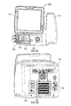
- FIGS. 2A and 2B are front and rear views of an exemplary ventilator according to certain aspects of the present disclosure.
- FIG. 3 is a schematic representation of a ventilator according to certain aspects of the present disclosure.
- FIG. 4 is a schematic depiction of a feedback system according to certain aspects of the present disclosure.
- FIG. 5 illustrates an exemplary schematic arrangement of a control system according to certain aspects of the present disclosure.
- FIG. 6 is a cross sectional view of a flow valve according to certain aspects of the present disclosure.
- gas shall be interpreted to mean both a single material in gaseous form, for example oxygen, and a mixture of two or more gases, for example air or heliox (a mixture of oxygen and helium).
- a gas may include water or other liquids in the form of vapor or suspended droplets.
- a gas may also include solid particulates suspended in the gas.
- pure when used with reference to a gas, means that the gas meets commonly accepted medical standards for purity and content.
- temperature sensor means a device configured to measure temperature and to provide a signal that is related to the measured temperature.
- a temperature sensor may include electronics to provide a drive current or voltage and/or measure a current or voltage.
- the electronics may further include conditioning and conversion circuitry and/or a processor to convert the measured value to a signal that may be in analog or digital form.
- pressure sensor means a device configured to measure a gas pressure and provide a signal that is related to the measured pressure.
- a pressure sensor may include electronics to provide a drive current or voltage and/or measure a current or voltage.
- the electronics may further include conditioning and conversion circuitry and/or a processor to convert the measured value to a signal that may be in analog or digital form.
- the pressure may be provided in absolute terms or “gauge” pressure, i.e., relative to ambient atmospheric pressure.
- An exhalation subsystem of a ventilator comprises an exhalation valve, an exhalation flow sensor, and a heated filter and water trap.
- the exhalation valve is a software-controlled valve that is used to adjust the flow of gas passing through the expiratory port of the ventilator to the outside environment.
- the exhalation valve is controlled by a software control signal and works in conjunction with a ventilator's gas delivery subsystems to maintain user set pressure control levels.
- the exhalation valve operates on the principle of a force balance across a control diaphragm, which is preferably a disposable valve membrane.
- a linear magneto-mechanical actuator controls a force on the diaphragm, which in turn controls the circuit or ventilator line pressure.
- the force generated by the actuator is based on a command from the software closed-loop controller.
- FIG. 1 depicts a patient 10 using an exemplary ventilation system with a ventilator 100 according to certain aspects of the present disclosure.
- the ventilator 100 operates as a gas source for providing gas to a patient (e.g., for respiration).
- the ventilator system includes a supply channel, tube, or “limb” 104 , a return or exhaust channel, tube, or limb 106 , a conditioning module 108 that may, for example, warm or humidify the air passing through the supply limb 104 .
- the supply and exhaust limbs 104 , 106 are both coupled to a patient interface device 102 that, in this example, is a mask that fits over the mouth of the patient 10 .
- the patient interface device 102 may include a nasal mask, an intubation device, or any other breathing interface device as known to those of skill in the art.
- FIGS. 2A and 2B are front and rear views of the ventilator 100 according to certain aspects of the present disclosure.
- the ventilator 100 has a housing 110 with an attached user interface 115 that, in certain embodiments, comprises a display and a touchscreen.
- the front of the housing 110 includes a supply port 155 for a supply limb, such as supply limb 104 in FIG. 1 , and a return port 150 for an exhaust, such as exhaust limb 106 in FIG. 1 .
- the return port 150 may be mounted over an access door 152 that provides access to a filter (not visible in FIG. 2A ) that filters and absorbs moisture from the exhaled breath of the patient 10 .
- FIG. 2B shows a rear view of the ventilator 100 with a gas inlet adapter 120 , an air intake port 140 , and a power interface 130 that may include a power plug connector and a circuit breaker reset switch. There may also be a rear interface panel 165 for connection to external instruments or a network interface cable.
- FIG. 3 illustrates a schematic depiction of the ventilator 100 having a control system 305 , system hardware 310 , user input 315 , output 320 , and feedback 325 .
- the control system 305 includes a ventilation control system 330 that receives user input 315 .
- the control system 305 includes hardware control systems that control respective hardware components of the ventilator 100 .
- the hardware control systems may include a blower control system 335 , a flow cassette control system 340 , and an exhalation valve control system 345 .
- the blower control system 335 controls a respective blower 350
- the flow cassette control system 340 controls a respective flow cassette 355
- the exhalation valve control system 345 controls a respective exhalation valve 360 .
- the system hardware 310 includes sensors 365 that detect information from the system hardware 310 , for example, the blower 350 , the flow cassette 355 , and the exhalation valve 360 .
- the sensors 365 produce one or more feedback signals 325 that are received by the ventilation control system 330 .
- the ventilation control system 330 receives the feedback control signals 325 and the user input 315 and sends information to an output 320 .
- the output 320 can include, for example, monitoring information and alarms.
- FIG. 4 illustrates a schematic depiction of an exhalation control feedback system 400 that determines an amount of gas flow 405 that is permitted to pass through an exhalation valve 410 .
- the illustrated embodiment of the feedback system 400 is based on a target pressure 420 and an actual circuit pressure 425 (or a pressure within a line of the ventilator 100 ).
- a processor 430 receives an input signal relating to the actual circuit pressure 425 and compares the actual circuit pressure 425 to the target pressure 420 . Based on this comparison, the processor 430 sends a command signal 435 to an exhalation valve driver 440 .
- the exhalation valve driver 440 is configured to control a position of the exhalation valve 410 to regulate the gas flow 405 through the exhalation valve 410 .
- the exhalation valve driver 440 sends a control current 445 to the exhalation valve 410 to maintain or adjust the exhalation valve 410 to modify or adjust the pressure within the ventilator line.
- the processor 430 sends a command 435 to the exhalation valve driver 440 to open the exhalation valve 410 to reduce pressure within the ventilator line.
- the exhalation valve driver 440 upon receiving the command 435 to relieve pressure, adjusts the control current 445 to the exhalation valve 410 to increase the opening of the exhalation valve 410 and relieve pressure within the ventilator line.
- the processor 430 receives position feedback 450 of the exhalation valve 410 via the exhalation valve driver 440 , such that the processor 430 is able to determine the degree to which the exhalation valve 410 is open.
- the processor 430 directs the driver 440 to adjust the control current 445 to the exhalation valve 410 to decrease the opening of the exhalation valve 410 such that pressure within the ventilator line is increased. If the actual circuit pressure 425 input to the processor 430 was found to be at an acceptable level or within an acceptable range, the processor 430 directs the driver 440 to maintain the control current 445 to the exhalation valve 410 to maintain the position of the exhalation valve 410 .
- FIG. 5 illustrates an exemplary schematic arrangement of a current control system 500 that illustrates some embodiments of a driver (e.g., the exhalation valve driver 440 of FIG. 4 ) operating to adjust a valve 503 (e.g., the exhalation valve 410 ).
- a driver e.g., the exhalation valve driver 440 of FIG. 4
- a valve 503 e.g., the exhalation valve 410
- a high frequency source 505 generates a signal having a high frequency
- a low frequency source 510 generates a signal having a low frequency.
- the high frequency signal and the low frequency signal are summed together, and the signal is amplified by a current amplifier 515 .
- the current amplifier 515 is a linear current output amplifier.
- the signal is then directed to a coil 520 (e.g., a force coil) that is configured to move at least partly within a fixed magnetic field 525 .
- the fixed magnetic field 525 is produced by a magnetic field generator, e.g., at least one permanent magnet 530 or a separate coil (not shown).
- the natural frequency of the coil 520 is such that the coil 520 responds to the low frequency component of the combined signal by movement within or in relation to the magnetic field, as illustrated by arrows 535 .
- the low frequency component is less than about 90% of the natural frequency of the coil 520 .
- the low frequency component is less than about 80% of the natural frequency of the coil 520 , and in yet further embodiments, the low frequency component is less than about 50% of the natural frequency of the coil 520 .
- the high frequency component of the combined signal preferably has a negligible effect on the position of the coil 520 such that the position of the coil 520 within the magnetic field is controlled substantially by the low frequency component.
- the high frequency component is more than 50% greater than the natural frequency of the coil 520 .
- the high frequency component can be between 50% and about 200% greater than the natural frequency of the coil 520 .
- the high frequency can be more than 200% greater than the natural frequency of the coil 520 .
- a detection coil 540 detects the high frequency component of the signal passing through the coil 520 , and the detection coil 540 sends a signal to a high frequency feedback processor 545 that determines, based on the detection coil 540 signal, a position of the coil 520 within the magnetic field 525 .
- a magnitude of the high frequency signal detected by the detection coil 540 is used to determine the position of the coil 520 within the magnetic field 525 .
- the high frequency feedback processor 545 also determines a velocity of the coil 520 within the magnetic field 525 and the high frequency feedback processor 545 sends a signal to the low frequency source 510 for providing feedback on the position and/or velocity of the coil 520 .
- the high frequency feedback processor 545 includes a position circuit 547 and a velocity circuit 548 .
- the low frequency source 510 also receives input from a sensor (not shown) within a ventilator line relating to how actual pressure 550 within the ventilator line compares to a target pressure 555 of the ventilator line. Based on (i) the input relating to the comparison of actual pressure 550 and the target pressure 555 and (ii) the input from the high frequency feedback processor 545 relating to the position of the coil 520 in relation to the magnetic field 525 , the low frequency source 510 determines whether the low frequency signal should be modified to change the position of the coil 520 in relation to the magnetic field 525 ,
- the low frequency source 510 changes the low frequency signal to move the coil 520 within the magnetic field 525 .
- the coil 520 is preferably coupled, directly (e.g., mechanically) or indirectly (e.g., magnetically), to a portion of the valve 503 that regulates flow through the valve 503 . Accordingly, movement of the coil 520 moves the portion of the valve 503 and changes an amount of gas passing through the valve 503 . As the amount of gas passing through the valve 503 changes, the pressure within the ventilator line changes, and the actual pressure 550 is detected and compared with the target pressure 555 .
- the target pressure 555 may include a minimum threshold pressure.
- the low frequency source 510 may be configured to close the valve 503 , such that substantially no gas from the exhalation line passes through the valve 503 .
- the valve 503 may remain closed until the actual pressure 550 within the exhalation line increases above the threshold pressure, at which time, the low frequency source 510 receives inputs reflecting that the valve 503 should be opened, and the source 510 changes the low frequency signal to move the coil 520 to a position in relation to the magnetic field 525 that corresponds to an opening of the valve 503 .
- the low frequency source 510 may produce a signal that maintains position of the coil 520 , and therefore the valve 503 , to further increase the actual pressure within the exhalation line.
- FIG. 6 is an exemplary cross sectional view of the exhalation valve 410 , which operates under the same or similar principles described above with respect to valve 503 depicted in FIG. 5 .
- the illustrated exhalation valve 410 includes a housing 605 that defines an internal chamber 610 .
- a coil 615 Disposed within the internal chamber 610 is a coil 615 that is positioned and axially movable within or in relation to a fixed magnetic field generator 620 .
- a sensor 625 Positioned about at least a portion of the magnetic field generator 620 .
- the sensor 625 is a detection coil that is configured to detect high frequency signals passing through the coil 615 . The high frequency signals detected by the sensor 625 are used to determine a position of the coil 615 within or in relation to the magnetic field generator 620 .
- a signal is communicated from the sensor 625 regarding a position of the coil 615 , and signals are directed to the coil 615 via a flexible communication cable 630 .
- signals directed to the coil 615 cause the coil 615 to move within the internal chamber 610 in relation to the magnetic field, movement of the coil 615 affects positioning of a convoluted diaphragm 635 and poppet 647 .
- the poppet 647 operates as a variable orifice of the valve 410 . Positioning of the poppet 647 with respect to the seat 645 affects the amount of fluid that passes through a valve having an opening 640 .
- Movement of the coil 615 can change a position of the plunger 625 by being directly coupled to the poppet 647 and moving the poppet 647 toward or away from a seat 645 , which defines the valve orifice as the gap between the poppet 647 and seat 645 .
- movement of the coil 615 can change a position of the poppet 647 by being indirectly coupled to the poppet 647 .
- a portion of the coil 615 and a portion of the poppet 647 may be magnetically opposed or attracted to each other. In such embodiments, movement of the coil 615 thereby opposes or attracts the portion of the poppet 647 .
- this indirect coupling can affect positioning of the poppet 647 in connection with the seat 645 of the valve without contact between the coil 615 and the poppet 647 .
- valves that can be used include, but are not limited to, a flap valve, a rotating disk valve, a duck-billed valve, etc.
- the exhalation valve 410 can also provide increased stability by damping the moving components of the exhalation valve 410 .
- a velocity of the coil 615 can be determined by a processor (e.g., processor 430 or high frequency feedback processor 545 ), which can include a velocity circuit that calculates a change of position with respect to time. The velocity can then be used to determine the desired damping.
- the damped frequency response is greater than or equal to about 26 Hz, and the damping coefficient that yields an under-damped or critically damped valve assembly.
- additional damping such as pneumatic viscous damping can be incorporated into the valve 410 to further tune the valve 410 to the specific application.
- the exhalation valve 410 can include a “fail-safe” open feature in case of loss of electrical power, software control, or loss of all inlet gases.
- the exhalation valve 410 can also be configured to switch to the “fail-safe” open configuration when the ventilator 100 is turned off. On successful completion of power on checks, the ventilator 100 will close the exhalation valve 410 and normal ventilation can commence.
- the exhalation valve 410 and other valves or ports will work in conjunction to (i) relieve pressure from the circuit down to ambient pressure conditions, (ii) allow ambient air to be available to the patient for breathing, and (iii) minimize re-breathing of gases.
- top should be understood as referring to an arbitrary frame of reference, rather than to the ordinary gravitational frame of reference.
- a top surface, a bottom surface, a front surface, and a rear surface may extend upwardly, downwardly, diagonally, or horizontally in a gravitational frame of reference.
- a phrase such as an “aspect” does not imply that such aspect is essential to the subject technology or that such aspect applies to all configurations of the subject technology.
- a disclosure relating to an aspect may apply to all configurations, or one or more configurations.
- a phrase such as an aspect may refer to one or more aspects and vice versa.
- a phrase such as an “embodiment” does not imply that such embodiment is essential to the subject technology or that such embodiment applies to all configurations of the subject technology.
- a disclosure relating to an embodiment may apply to all embodiments, or one or more embodiments.
- a phrase such an embodiment may refer to one or more embodiments and vice versa.
Abstract
Description
Claims (11)
Priority Applications (28)
| Application Number | Priority Date | Filing Date | Title |
|---|---|---|---|
| US13/931,418 US9433743B2 (en) | 2013-06-28 | 2013-06-28 | Ventilator exhalation flow valve |
| BR112015032320A BR112015032320A2 (en) | 2013-06-28 | 2014-06-27 | ventilation system |
| PCT/US2014/044724 WO2014210552A1 (en) | 2013-06-28 | 2014-06-27 | Ventilator flow valve |
| RU2015155886A RU2015155886A (en) | 2013-06-28 | 2014-06-27 | LUNG ARTIFICIAL VENTILATION SYSTEM |
| ES14744689.2T ES2632484T3 (en) | 2013-06-28 | 2014-06-27 | Fan system |
| RU2015155882A RU2015155882A (en) | 2013-06-28 | 2014-06-27 | RESPIRATORY FLOW CONTROL VALVE |
| US14/318,504 US20150007815A1 (en) | 2013-06-28 | 2014-06-27 | Ventilator system |
| MX2015016912A MX349592B (en) | 2013-06-28 | 2014-06-27 | Ventilator flow valve. |
| ES14742096.2T ES2636654T3 (en) | 2013-06-28 | 2014-06-27 | Fan flow valve |
| CN201480037104.8A CN105451797B (en) | 2013-06-28 | 2014-06-27 | ventilator flow valve |
| CA2915686A CA2915686A1 (en) | 2013-06-28 | 2014-06-27 | Ventilator system |
| CN201710565582.1A CN107252514A (en) | 2013-06-28 | 2014-06-27 | Ventilator flow valve |
| EP14744689.2A EP3013400B8 (en) | 2013-06-28 | 2014-06-27 | Ventilator system |
| EP20162775.9A EP3689404A1 (en) | 2013-06-28 | 2014-06-27 | Ventilator system |
| CN201480037090.XA CN105358202B (en) | 2013-06-28 | 2014-06-27 | ventilator system |
| BR112015031635A BR112015031635A2 (en) | 2013-06-28 | 2014-06-27 | fan flow valve |
| CA2914858A CA2914858A1 (en) | 2013-06-28 | 2014-06-27 | Ventilator flow valve |
| EP14742096.2A EP3013398B1 (en) | 2013-06-28 | 2014-06-27 | Ventilator flow valve |
| AU2014302094A AU2014302094A1 (en) | 2013-06-28 | 2014-06-27 | Ventilator flow valve |
| MX2015017335A MX2015017335A (en) | 2013-06-28 | 2014-06-27 | Ventilator system. |
| CN201710584523.9A CN107362424A (en) | 2013-06-28 | 2014-06-27 | Ventilator system |
| AU2014302108A AU2014302108A1 (en) | 2013-06-28 | 2014-06-27 | Ventilator system |
| US14/318,274 US9962514B2 (en) | 2013-06-28 | 2014-06-27 | Ventilator flow valve |
| EP17162581.7A EP3219350B1 (en) | 2013-06-28 | 2014-06-27 | Ventilator system |
| PCT/US2014/044743 WO2014210566A2 (en) | 2013-06-28 | 2014-06-27 | Ventilator system |
| JP2016524266A JP2016523662A (en) | 2013-06-28 | 2014-06-27 | Ventilator flow valve |
| JP2016524271A JP2016526639A (en) | 2013-06-28 | 2014-06-27 | Ventilator system |
| US15/233,853 US9962515B2 (en) | 2013-06-28 | 2016-08-10 | Ventilator exhalation flow valve |
Applications Claiming Priority (1)
| Application Number | Priority Date | Filing Date | Title |
|---|---|---|---|
| US13/931,418 US9433743B2 (en) | 2013-06-28 | 2013-06-28 | Ventilator exhalation flow valve |
Related Parent Applications (1)
| Application Number | Title | Priority Date | Filing Date |
|---|---|---|---|
| US13/931,496 Continuation-In-Part US9795757B2 (en) | 2013-06-28 | 2013-06-28 | Fluid inlet adapter |
Related Child Applications (3)
| Application Number | Title | Priority Date | Filing Date |
|---|---|---|---|
| US13/931,566 Continuation-In-Part US9707369B2 (en) | 2013-06-28 | 2013-06-28 | Modular flow cassette |
| US14/318,274 Continuation-In-Part US9962514B2 (en) | 2013-06-28 | 2014-06-27 | Ventilator flow valve |
| US15/233,853 Division US9962515B2 (en) | 2013-06-28 | 2016-08-10 | Ventilator exhalation flow valve |
Publications (2)
| Publication Number | Publication Date |
|---|---|
| US20150000662A1 US20150000662A1 (en) | 2015-01-01 |
| US9433743B2 true US9433743B2 (en) | 2016-09-06 |
Family
ID=51213033
Family Applications (2)
| Application Number | Title | Priority Date | Filing Date |
|---|---|---|---|
| US13/931,418 Active 2034-06-14 US9433743B2 (en) | 2013-06-28 | 2013-06-28 | Ventilator exhalation flow valve |
| US15/233,853 Expired - Fee Related US9962515B2 (en) | 2013-06-28 | 2016-08-10 | Ventilator exhalation flow valve |
Family Applications After (1)
| Application Number | Title | Priority Date | Filing Date |
|---|---|---|---|
| US15/233,853 Expired - Fee Related US9962515B2 (en) | 2013-06-28 | 2016-08-10 | Ventilator exhalation flow valve |
Country Status (11)
| Country | Link |
|---|---|
| US (2) | US9433743B2 (en) |
| EP (1) | EP3013398B1 (en) |
| JP (1) | JP2016523662A (en) |
| CN (2) | CN107252514A (en) |
| AU (1) | AU2014302094A1 (en) |
| BR (1) | BR112015031635A2 (en) |
| CA (1) | CA2914858A1 (en) |
| ES (1) | ES2636654T3 (en) |
| MX (1) | MX349592B (en) |
| RU (1) | RU2015155882A (en) |
| WO (1) | WO2014210552A1 (en) |
Families Citing this family (7)
| Publication number | Priority date | Publication date | Assignee | Title |
|---|---|---|---|---|
| CA3035508A1 (en) | 2011-07-13 | 2013-01-17 | Fisher & Paykel Healthcare Limited | Impeller and motor assembly |
| DE212013000256U1 (en) | 2012-12-18 | 2015-07-22 | Fisher & Paykel Healthcare Ltd. | Impeller and rotor assembly |
| WO2015200878A1 (en) * | 2014-06-27 | 2015-12-30 | Carefusion 303, Inc. | Ventilator flow valve |
| AU2017345460B2 (en) * | 2016-10-19 | 2022-05-26 | Medtec Medical, Inc. | Electronic flowmeter with regulator |
| CN111033067B (en) | 2017-04-23 | 2022-01-14 | 费雪派克医疗保健有限公司 | Breathing assistance apparatus |
| CN109646774B (en) * | 2018-12-27 | 2021-10-22 | 常州唯精医疗机器人有限公司 | Air flue management manipulator assisting positive pressure ventilation of mask |
| CN117287549A (en) * | 2022-06-20 | 2023-12-26 | 华为技术有限公司 | Electromagnetic valve and equipment |
Citations (89)
| Publication number | Priority date | Publication date | Assignee | Title |
|---|---|---|---|---|
| US2037880A (en) | 1933-11-17 | 1936-04-21 | Hartzell Industries | Fan |
| US2510125A (en) | 1946-07-30 | 1950-06-06 | Lawrence W Meakin | Connector for fluid or electrical lines or both |
| US2634311A (en) | 1950-01-31 | 1953-04-07 | Ralph E Darling | Composite fluid and electrical connector |
| US3140042A (en) | 1961-08-15 | 1964-07-07 | Fujii Noriyoshi | Wheels for centrifugal fans of the forward curved multiblade type |
| US3673541A (en) | 1970-08-06 | 1972-06-27 | Amp Inc | Composite electrical and fluid or air connector |
| US3776215A (en) | 1971-11-01 | 1973-12-04 | Hugh J Mc | Humidifier means |
| US3788765A (en) | 1971-11-18 | 1974-01-29 | Laval Turbine | Low specific speed compressor |
| US4243357A (en) | 1979-08-06 | 1981-01-06 | Cummins Engine Company, Inc. | Turbomachine |
| JPS56597A (en) | 1979-06-14 | 1981-01-07 | Matsushita Electric Ind Co Ltd | Motor blower |
| US4543041A (en) | 1981-08-07 | 1985-09-24 | Holset Engineering Company Limited | Impellor for centrifugal compressor |
| US4562744A (en) | 1984-05-04 | 1986-01-07 | Precision Measurement, Inc. | Method and apparatus for measuring the flowrate of compressible fluids |
| US4571801A (en) | 1983-06-15 | 1986-02-25 | Mks Instruments, Inc. | Method of manufacturing a cartridge unit for establishing controlled laminar-flow conditions |
| US4754651A (en) | 1986-04-18 | 1988-07-05 | Shortridge Instruments, Inc. | Differential pressure apparatus for measuring flow and velocity |
| US4809742A (en) * | 1988-04-18 | 1989-03-07 | Pneumo Abex Corporation | Control valve assembly including valve position sensor |
| US4825904A (en) | 1988-04-18 | 1989-05-02 | Pneumo Abex Corporation | Two position flow control valve assembly with position sensing |
| US4909545A (en) | 1982-12-15 | 1990-03-20 | Larry Hohol | Coupling |
| US4978281A (en) | 1988-08-19 | 1990-12-18 | Conger William W Iv | Vibration dampened blower |
| US5064346A (en) | 1988-06-17 | 1991-11-12 | Matsushita Electric Industrial Co., Ltd. | Impeller of multiblade blower |
| US5127400A (en) * | 1990-03-23 | 1992-07-07 | Bird Products Corp. | Ventilator exhalation valve |
| US5265594A (en) | 1990-10-30 | 1993-11-30 | Siemens Aktiengesellschaft | Apparatus for regulating the flow-through amount of a flowing medium |
| US5277196A (en) | 1992-03-31 | 1994-01-11 | The United States Of America As Represented By The Department Of Health And Human Services | Portable spirometer with improved accuracy |
| US5295397A (en) | 1991-07-15 | 1994-03-22 | The Texas A & M University System | Slotted orifice flowmeter |
| US5331995A (en) | 1992-07-17 | 1994-07-26 | Bear Medical Systems, Inc. | Flow control system for medical ventilator |
| US5339807A (en) * | 1992-09-22 | 1994-08-23 | Puritan-Bennett Corporation | Exhalation valve stabilizing apparatus |
| US5365795A (en) | 1993-05-20 | 1994-11-22 | Brower Jr William B | Improved method for determining flow rates in venturis, orifices and flow nozzles involving total pressure and static pressure measurements |
| US5461932A (en) | 1991-07-15 | 1995-10-31 | Texas A & M University System | Slotted orifice flowmeter |
| US5478206A (en) | 1991-03-23 | 1995-12-26 | Robert Bosch Gmbh | Impeller for a radial fan |
| US5537992A (en) | 1994-05-06 | 1996-07-23 | Siemens Elema Ab | Anesthetic system having electronic safety interlock system |
| US5572992A (en) | 1994-03-04 | 1996-11-12 | Instrumentarium Corp. | Method and apparatus for identifying an anesthetic fluid container and/or for detecting a connection between the container and a conduit supplying a gas to a patient |
| US5604681A (en) | 1994-06-03 | 1997-02-18 | Dover Corporation | Coupler identification systems |
| US5606236A (en) * | 1995-01-17 | 1997-02-25 | Eaton Corporation | Two wire position sense and control of modulating gas valve or other electromechanical actuators |
| EP0829793A1 (en) | 1996-09-06 | 1998-03-18 | Berkin B.V. | Method for momentarily identifying a gas or liquid flow, and device for carrying out the method |
| US5771884A (en) * | 1997-03-14 | 1998-06-30 | Nellcor Puritan Bennett Incorporated | Magnetic exhalation valve with compensation for temperature and patient airway pressure induced changes to the magnetic field |
| US5918596A (en) | 1997-04-22 | 1999-07-06 | Instrumentarium Corp. | Special gas dose delivery apparatus for respiration equipment |
| US5954051A (en) * | 1997-02-06 | 1999-09-21 | Instrumentarium Oy | Ventilator for intensified breathing and valve in patient conduit of apparatus for intensified breathing |
| US6151557A (en) | 1998-01-13 | 2000-11-21 | Rosemount Inc. | Friction flowmeter with improved software |
| WO2001038832A2 (en) | 1999-11-24 | 2001-05-31 | S.C. Ack S.R.L. | System for metering fluids |
| EP1127583A2 (en) | 2000-02-24 | 2001-08-29 | Siemens-Elema AB | Conduit with transmission line |
| US20020085952A1 (en) | 2000-09-27 | 2002-07-04 | Ellingboe Bruce S. | Blood perfusion system |
| US6422092B1 (en) | 1998-09-10 | 2002-07-23 | The Texas A&M University System | Multiple-phase flow meter |
| US20020198668A1 (en) | 2001-04-24 | 2002-12-26 | Lull John M. | System and method for a mass flow controller |
| US6553923B2 (en) | 2000-08-30 | 2003-04-29 | William Stuart Gatley, Jr. | Blower housing with maximized interior spacing |
| US20030106554A1 (en) | 2001-11-30 | 2003-06-12 | De Silva Adrian D. | Gas identification system and volumetric ally correct gas delivery system |
| US6578818B1 (en) | 1998-03-10 | 2003-06-17 | Robert Bosch Gmbh | Valve device |
| US6609431B1 (en) | 2000-09-29 | 2003-08-26 | Xellogy, Inc. | Flow measuring device based on predetermine class of liquid |
| US6622724B1 (en) | 2000-06-19 | 2003-09-23 | Respironics, Inc. | Impeller and a pressure support system and method using such an impeller |
| US20030220605A1 (en) | 2002-05-24 | 2003-11-27 | Bowman Joseph H. | Disposable medical fluid unit having rigid frame |
| US20040074311A1 (en) | 2002-07-19 | 2004-04-22 | Celerity Group, Inc. | Methods and apparatus for pressure compensation in a mass flow controller |
| US20040177703A1 (en) | 2003-03-12 | 2004-09-16 | Schumacher Mark S. | Flow instrument with multisensors |
| US6820620B2 (en) * | 2000-12-22 | 2004-11-23 | Jean-Denis Rochat | Respiratory assistance apparatus |
| US20050004534A1 (en) | 2001-12-26 | 2005-01-06 | Lockwood Jeffery S | Vented vacuum bandage and method |
| US6945123B1 (en) | 2004-06-28 | 2005-09-20 | The General Electric Company | Gas flow sensor having redundant flow sensing capability |
| WO2006024532A1 (en) | 2004-09-03 | 2006-03-09 | Ric Investments, Llc | Gas flow control in a ventilator |
| US20060144163A1 (en) | 2002-11-20 | 2006-07-06 | Harri Friberg | Gas flow measuring device |
| US20060162466A1 (en) | 2002-07-19 | 2006-07-27 | Christopher Wargo | Fluid flow measuring and proportional fluid flow control device |
| US20060236781A1 (en) | 2003-07-03 | 2006-10-26 | Fujikin Incorporated | Differential pressure type flowmeter and differential pressure type flowmeter controller |
| US20070193369A1 (en) | 2006-02-15 | 2007-08-23 | Evans Russell N | Multiphasic overreading correction in a process variable transmitter |
| US20070265877A1 (en) | 2006-05-12 | 2007-11-15 | Rice Caeli B D | Informative accessories |
| US20070277824A1 (en) | 2006-05-31 | 2007-12-06 | Acoba, L.L.C. | Hose Connection System For Narially Sensitive Diagnostic Devices |
| US20080059084A1 (en) | 2006-09-05 | 2008-03-06 | Celerity, Inc. | Multi-gas flow device |
| US20090038615A1 (en) | 2006-02-23 | 2009-02-12 | Meditren Limited | Breathing apparatus |
| US20090093774A1 (en) | 2007-10-04 | 2009-04-09 | Baxter International Inc. | Ambulatory pump with intelligent flow control |
| US20090113996A1 (en) | 2007-10-04 | 2009-05-07 | Baxter International Inc. | System and method for measuring liquid viscosity in a fluid delivery system |
| US20090293634A1 (en) | 2008-05-27 | 2009-12-03 | Joo Tim Ong | Method of measuring multiphase flow |
| US20090326839A1 (en) | 2008-06-27 | 2009-12-31 | Steven Bruce Rogers | Velocity-enhanced flow measurement |
| US20100139660A1 (en) * | 2008-12-10 | 2010-06-10 | Carmeli Adahan | Pump and exhalation valve control for respirator apparatus |
| US20100229967A1 (en) | 2009-03-11 | 2010-09-16 | Horiba Stec, Co., Ltd. | Mass flow controller verifying system, verifying method and verifying program |
| US20100236552A1 (en) | 2005-08-15 | 2010-09-23 | Resmed Limited | Cpap Systems |
| US20100307490A1 (en) | 2007-11-14 | 2010-12-09 | Stefan Broborg | Patient cassette with variable patient circuit volume |
| US20110100364A1 (en) | 2009-11-02 | 2011-05-05 | Joseph Dee Faram | Multiple conduit connector apparatus and method |
| WO2011055254A1 (en) | 2009-11-09 | 2011-05-12 | Koninklijke Philips Electronics N.V. | Flow sensing device with temperature compensation |
| US20110126834A1 (en) * | 2009-12-01 | 2011-06-02 | Nellcor Puritan Bennett Llc | Exhalation Valve Assembly With Integral Flow Sensor |
| EP2402616A1 (en) | 2009-07-13 | 2012-01-04 | Mitsubishi Heavy Industries, Ltd. | Impeller and rotary machine |
| US20120185102A1 (en) | 2011-01-18 | 2012-07-19 | Flow Control Industries, Inc. | Pressure compensated flow rate controller with btu meter |
| US20120204874A1 (en) | 2009-10-28 | 2012-08-16 | Koninklijke Philips Electronics N.V. | Pressure support sustem with inductive tubing |
| US20120229272A1 (en) | 2009-11-11 | 2012-09-13 | Koninklijke Philips Electronics N.V. | Wireless identification of a component of a pressure support system |
| US20120285454A1 (en) | 2009-10-29 | 2012-11-15 | Resmed Ltd. | Patient ventilation device and components thereof |
| US20120318383A1 (en) | 2011-06-17 | 2012-12-20 | Horiba Stec, Co., Ltd. | Flow rate measuring device and flow rate controller |
| WO2013002699A1 (en) | 2011-06-30 | 2013-01-03 | Cejn Ab | Quick coupling for pipes/hoses with locking feature |
| US20130079667A1 (en) | 2011-09-28 | 2013-03-28 | General Electric Company | Flow sensor with mems sensing device and method for using same |
| US8504318B2 (en) | 2008-03-05 | 2013-08-06 | Brooks Instruments, Llc | System, method and computer program for determining fluid flow rate using a pressure sensor and a thermal mass flow sensor |
| US20130220314A1 (en) | 2012-02-29 | 2013-08-29 | General Electric Company | Medical vaporizer with porous vaporization element |
| US20130247905A1 (en) | 2010-12-03 | 2013-09-26 | Intersurgical Ag | Breathing systems |
| US20140054479A1 (en) | 2011-12-30 | 2014-02-27 | Beijing Aeonmed Co., Ltd. | Flow control proportional valve |
| US20140066880A1 (en) | 2011-06-22 | 2014-03-06 | Crisi Medical Systems, Inc. | Selectively Controlling Fluid Flow Through A Fluid Pathway |
| US20140182590A1 (en) * | 2012-12-28 | 2014-07-03 | Newport Medical Instruments, Incorporated | Ventilator pressure oscillation filter |
| US20140251322A1 (en) | 2011-11-01 | 2014-09-11 | Intersurgical Ag | Breathing systems |
| US20150096560A1 (en) | 2012-04-27 | 2015-04-09 | Fisher & Paykel Place, East Limited | Usability features for respiratory humidification system |
| US20150143921A1 (en) | 2012-06-04 | 2015-05-28 | Hans-Jürgen Postberg | Device for measuring differential pressure |
Family Cites Families (5)
| Publication number | Priority date | Publication date | Assignee | Title |
|---|---|---|---|---|
| JP2533741B2 (en) | 1991-07-30 | 1996-09-11 | オーラ システムズ,インコーポレーテッド | Variable gain servo auxiliary device |
| CN101225881A (en) * | 2007-12-19 | 2008-07-23 | 哈尔滨工业大学 | High speed electrohydraulic open and close valve driven directly by ultra-magnetostriction actuator |
| CN102155570B (en) * | 2011-04-22 | 2012-08-29 | 浙江大学 | Pneumatic high-speed switch valve driven by giant magnetostriction |
| US20140326242A1 (en) | 2011-12-01 | 2014-11-06 | Koninklijke Philips N.V. | Sysems and methods for using partial co2 rebreathing integrated in a ventilator and measurements thereof to determine noninvasive cardiac output |
| CN102927292B (en) * | 2012-11-01 | 2013-12-25 | 浙江理工大学 | Solenoid valve and weft yarn tension device |
-
2013
- 2013-06-28 US US13/931,418 patent/US9433743B2/en active Active
-
2014
- 2014-06-27 ES ES14742096.2T patent/ES2636654T3/en active Active
- 2014-06-27 CN CN201710565582.1A patent/CN107252514A/en active Pending
- 2014-06-27 WO PCT/US2014/044724 patent/WO2014210552A1/en active Application Filing
- 2014-06-27 RU RU2015155882A patent/RU2015155882A/en not_active Application Discontinuation
- 2014-06-27 CA CA2914858A patent/CA2914858A1/en not_active Abandoned
- 2014-06-27 JP JP2016524266A patent/JP2016523662A/en active Pending
- 2014-06-27 BR BR112015031635A patent/BR112015031635A2/en not_active Application Discontinuation
- 2014-06-27 MX MX2015016912A patent/MX349592B/en active IP Right Grant
- 2014-06-27 EP EP14742096.2A patent/EP3013398B1/en not_active Not-in-force
- 2014-06-27 CN CN201480037104.8A patent/CN105451797B/en not_active Expired - Fee Related
- 2014-06-27 AU AU2014302094A patent/AU2014302094A1/en not_active Abandoned
-
2016
- 2016-08-10 US US15/233,853 patent/US9962515B2/en not_active Expired - Fee Related
Patent Citations (91)
| Publication number | Priority date | Publication date | Assignee | Title |
|---|---|---|---|---|
| US2037880A (en) | 1933-11-17 | 1936-04-21 | Hartzell Industries | Fan |
| US2510125A (en) | 1946-07-30 | 1950-06-06 | Lawrence W Meakin | Connector for fluid or electrical lines or both |
| US2634311A (en) | 1950-01-31 | 1953-04-07 | Ralph E Darling | Composite fluid and electrical connector |
| US3140042A (en) | 1961-08-15 | 1964-07-07 | Fujii Noriyoshi | Wheels for centrifugal fans of the forward curved multiblade type |
| US3673541A (en) | 1970-08-06 | 1972-06-27 | Amp Inc | Composite electrical and fluid or air connector |
| US3776215A (en) | 1971-11-01 | 1973-12-04 | Hugh J Mc | Humidifier means |
| US3788765A (en) | 1971-11-18 | 1974-01-29 | Laval Turbine | Low specific speed compressor |
| JPS56597A (en) | 1979-06-14 | 1981-01-07 | Matsushita Electric Ind Co Ltd | Motor blower |
| US4243357A (en) | 1979-08-06 | 1981-01-06 | Cummins Engine Company, Inc. | Turbomachine |
| US4543041A (en) | 1981-08-07 | 1985-09-24 | Holset Engineering Company Limited | Impellor for centrifugal compressor |
| US4909545A (en) | 1982-12-15 | 1990-03-20 | Larry Hohol | Coupling |
| US4571801A (en) | 1983-06-15 | 1986-02-25 | Mks Instruments, Inc. | Method of manufacturing a cartridge unit for establishing controlled laminar-flow conditions |
| US4562744A (en) | 1984-05-04 | 1986-01-07 | Precision Measurement, Inc. | Method and apparatus for measuring the flowrate of compressible fluids |
| US4754651A (en) | 1986-04-18 | 1988-07-05 | Shortridge Instruments, Inc. | Differential pressure apparatus for measuring flow and velocity |
| US4809742A (en) * | 1988-04-18 | 1989-03-07 | Pneumo Abex Corporation | Control valve assembly including valve position sensor |
| US4825904A (en) | 1988-04-18 | 1989-05-02 | Pneumo Abex Corporation | Two position flow control valve assembly with position sensing |
| US5064346A (en) | 1988-06-17 | 1991-11-12 | Matsushita Electric Industrial Co., Ltd. | Impeller of multiblade blower |
| US4978281A (en) | 1988-08-19 | 1990-12-18 | Conger William W Iv | Vibration dampened blower |
| US5127400A (en) * | 1990-03-23 | 1992-07-07 | Bird Products Corp. | Ventilator exhalation valve |
| US5265594A (en) | 1990-10-30 | 1993-11-30 | Siemens Aktiengesellschaft | Apparatus for regulating the flow-through amount of a flowing medium |
| US5478206A (en) | 1991-03-23 | 1995-12-26 | Robert Bosch Gmbh | Impeller for a radial fan |
| US5461932A (en) | 1991-07-15 | 1995-10-31 | Texas A & M University System | Slotted orifice flowmeter |
| US5295397A (en) | 1991-07-15 | 1994-03-22 | The Texas A & M University System | Slotted orifice flowmeter |
| US5277196A (en) | 1992-03-31 | 1994-01-11 | The United States Of America As Represented By The Department Of Health And Human Services | Portable spirometer with improved accuracy |
| US5331995A (en) | 1992-07-17 | 1994-07-26 | Bear Medical Systems, Inc. | Flow control system for medical ventilator |
| US5339807A (en) * | 1992-09-22 | 1994-08-23 | Puritan-Bennett Corporation | Exhalation valve stabilizing apparatus |
| US5365795A (en) | 1993-05-20 | 1994-11-22 | Brower Jr William B | Improved method for determining flow rates in venturis, orifices and flow nozzles involving total pressure and static pressure measurements |
| US5572992A (en) | 1994-03-04 | 1996-11-12 | Instrumentarium Corp. | Method and apparatus for identifying an anesthetic fluid container and/or for detecting a connection between the container and a conduit supplying a gas to a patient |
| US5537992A (en) | 1994-05-06 | 1996-07-23 | Siemens Elema Ab | Anesthetic system having electronic safety interlock system |
| US5604681A (en) | 1994-06-03 | 1997-02-18 | Dover Corporation | Coupler identification systems |
| US5606236A (en) * | 1995-01-17 | 1997-02-25 | Eaton Corporation | Two wire position sense and control of modulating gas valve or other electromechanical actuators |
| EP0829793A1 (en) | 1996-09-06 | 1998-03-18 | Berkin B.V. | Method for momentarily identifying a gas or liquid flow, and device for carrying out the method |
| US5954051A (en) * | 1997-02-06 | 1999-09-21 | Instrumentarium Oy | Ventilator for intensified breathing and valve in patient conduit of apparatus for intensified breathing |
| US5771884A (en) * | 1997-03-14 | 1998-06-30 | Nellcor Puritan Bennett Incorporated | Magnetic exhalation valve with compensation for temperature and patient airway pressure induced changes to the magnetic field |
| US5918596A (en) | 1997-04-22 | 1999-07-06 | Instrumentarium Corp. | Special gas dose delivery apparatus for respiration equipment |
| US6151557A (en) | 1998-01-13 | 2000-11-21 | Rosemount Inc. | Friction flowmeter with improved software |
| US6578818B1 (en) | 1998-03-10 | 2003-06-17 | Robert Bosch Gmbh | Valve device |
| US6422092B1 (en) | 1998-09-10 | 2002-07-23 | The Texas A&M University System | Multiple-phase flow meter |
| WO2001038832A2 (en) | 1999-11-24 | 2001-05-31 | S.C. Ack S.R.L. | System for metering fluids |
| EP1127583A2 (en) | 2000-02-24 | 2001-08-29 | Siemens-Elema AB | Conduit with transmission line |
| US6622724B1 (en) | 2000-06-19 | 2003-09-23 | Respironics, Inc. | Impeller and a pressure support system and method using such an impeller |
| US6553923B2 (en) | 2000-08-30 | 2003-04-29 | William Stuart Gatley, Jr. | Blower housing with maximized interior spacing |
| US20020085952A1 (en) | 2000-09-27 | 2002-07-04 | Ellingboe Bruce S. | Blood perfusion system |
| US6609431B1 (en) | 2000-09-29 | 2003-08-26 | Xellogy, Inc. | Flow measuring device based on predetermine class of liquid |
| US6820620B2 (en) * | 2000-12-22 | 2004-11-23 | Jean-Denis Rochat | Respiratory assistance apparatus |
| US20020198668A1 (en) | 2001-04-24 | 2002-12-26 | Lull John M. | System and method for a mass flow controller |
| US20030106554A1 (en) | 2001-11-30 | 2003-06-12 | De Silva Adrian D. | Gas identification system and volumetric ally correct gas delivery system |
| US20050004534A1 (en) | 2001-12-26 | 2005-01-06 | Lockwood Jeffery S | Vented vacuum bandage and method |
| US20030220605A1 (en) | 2002-05-24 | 2003-11-27 | Bowman Joseph H. | Disposable medical fluid unit having rigid frame |
| US20060162466A1 (en) | 2002-07-19 | 2006-07-27 | Christopher Wargo | Fluid flow measuring and proportional fluid flow control device |
| US20040074311A1 (en) | 2002-07-19 | 2004-04-22 | Celerity Group, Inc. | Methods and apparatus for pressure compensation in a mass flow controller |
| US20060144163A1 (en) | 2002-11-20 | 2006-07-06 | Harri Friberg | Gas flow measuring device |
| US20040177703A1 (en) | 2003-03-12 | 2004-09-16 | Schumacher Mark S. | Flow instrument with multisensors |
| US20060236781A1 (en) | 2003-07-03 | 2006-10-26 | Fujikin Incorporated | Differential pressure type flowmeter and differential pressure type flowmeter controller |
| US6945123B1 (en) | 2004-06-28 | 2005-09-20 | The General Electric Company | Gas flow sensor having redundant flow sensing capability |
| US20080092891A1 (en) | 2004-09-03 | 2008-04-24 | Anagram Consultants Ag | Gas Flow Control In A Ventilator |
| WO2006024532A1 (en) | 2004-09-03 | 2006-03-09 | Ric Investments, Llc | Gas flow control in a ventilator |
| US20100236552A1 (en) | 2005-08-15 | 2010-09-23 | Resmed Limited | Cpap Systems |
| US20070193369A1 (en) | 2006-02-15 | 2007-08-23 | Evans Russell N | Multiphasic overreading correction in a process variable transmitter |
| US20090038615A1 (en) | 2006-02-23 | 2009-02-12 | Meditren Limited | Breathing apparatus |
| US20070265877A1 (en) | 2006-05-12 | 2007-11-15 | Rice Caeli B D | Informative accessories |
| US20070277824A1 (en) | 2006-05-31 | 2007-12-06 | Acoba, L.L.C. | Hose Connection System For Narially Sensitive Diagnostic Devices |
| US20080059084A1 (en) | 2006-09-05 | 2008-03-06 | Celerity, Inc. | Multi-gas flow device |
| US20090093774A1 (en) | 2007-10-04 | 2009-04-09 | Baxter International Inc. | Ambulatory pump with intelligent flow control |
| US20090113996A1 (en) | 2007-10-04 | 2009-05-07 | Baxter International Inc. | System and method for measuring liquid viscosity in a fluid delivery system |
| US20100307490A1 (en) | 2007-11-14 | 2010-12-09 | Stefan Broborg | Patient cassette with variable patient circuit volume |
| US8504318B2 (en) | 2008-03-05 | 2013-08-06 | Brooks Instruments, Llc | System, method and computer program for determining fluid flow rate using a pressure sensor and a thermal mass flow sensor |
| US20090293634A1 (en) | 2008-05-27 | 2009-12-03 | Joo Tim Ong | Method of measuring multiphase flow |
| US20090326839A1 (en) | 2008-06-27 | 2009-12-31 | Steven Bruce Rogers | Velocity-enhanced flow measurement |
| US20100139660A1 (en) * | 2008-12-10 | 2010-06-10 | Carmeli Adahan | Pump and exhalation valve control for respirator apparatus |
| US20100229967A1 (en) | 2009-03-11 | 2010-09-16 | Horiba Stec, Co., Ltd. | Mass flow controller verifying system, verifying method and verifying program |
| EP2402616A1 (en) | 2009-07-13 | 2012-01-04 | Mitsubishi Heavy Industries, Ltd. | Impeller and rotary machine |
| US20120204874A1 (en) | 2009-10-28 | 2012-08-16 | Koninklijke Philips Electronics N.V. | Pressure support sustem with inductive tubing |
| US20120285454A1 (en) | 2009-10-29 | 2012-11-15 | Resmed Ltd. | Patient ventilation device and components thereof |
| US20110100364A1 (en) | 2009-11-02 | 2011-05-05 | Joseph Dee Faram | Multiple conduit connector apparatus and method |
| WO2011055254A1 (en) | 2009-11-09 | 2011-05-12 | Koninklijke Philips Electronics N.V. | Flow sensing device with temperature compensation |
| US20120226449A1 (en) | 2009-11-09 | 2012-09-06 | Koninklijke Philips Electronics N.V. | Flow sensing device with temperature compensation |
| US20120229272A1 (en) | 2009-11-11 | 2012-09-13 | Koninklijke Philips Electronics N.V. | Wireless identification of a component of a pressure support system |
| US20110126834A1 (en) * | 2009-12-01 | 2011-06-02 | Nellcor Puritan Bennett Llc | Exhalation Valve Assembly With Integral Flow Sensor |
| US20130247905A1 (en) | 2010-12-03 | 2013-09-26 | Intersurgical Ag | Breathing systems |
| US20120185102A1 (en) | 2011-01-18 | 2012-07-19 | Flow Control Industries, Inc. | Pressure compensated flow rate controller with btu meter |
| US20120318383A1 (en) | 2011-06-17 | 2012-12-20 | Horiba Stec, Co., Ltd. | Flow rate measuring device and flow rate controller |
| US20140066880A1 (en) | 2011-06-22 | 2014-03-06 | Crisi Medical Systems, Inc. | Selectively Controlling Fluid Flow Through A Fluid Pathway |
| WO2013002699A1 (en) | 2011-06-30 | 2013-01-03 | Cejn Ab | Quick coupling for pipes/hoses with locking feature |
| US20130079667A1 (en) | 2011-09-28 | 2013-03-28 | General Electric Company | Flow sensor with mems sensing device and method for using same |
| US20140251322A1 (en) | 2011-11-01 | 2014-09-11 | Intersurgical Ag | Breathing systems |
| US20140054479A1 (en) | 2011-12-30 | 2014-02-27 | Beijing Aeonmed Co., Ltd. | Flow control proportional valve |
| US20130220314A1 (en) | 2012-02-29 | 2013-08-29 | General Electric Company | Medical vaporizer with porous vaporization element |
| US20150096560A1 (en) | 2012-04-27 | 2015-04-09 | Fisher & Paykel Place, East Limited | Usability features for respiratory humidification system |
| US20150143921A1 (en) | 2012-06-04 | 2015-05-28 | Hans-Jürgen Postberg | Device for measuring differential pressure |
| US20140182590A1 (en) * | 2012-12-28 | 2014-07-03 | Newport Medical Instruments, Incorporated | Ventilator pressure oscillation filter |
Non-Patent Citations (11)
| Title |
|---|
| International Search Report and Written Opinion for Application No. PCT/US2015/038155, dated Dec. 17, 2015, 18 pages. |
| International Search Report and Written Opinion for Application No. PCT/US2015/038157, dated Nov. 5, 2015, 12 pages. |
| International Search Report and Written Opinion for International Application No. PCT/US2014/044737, dated May 19, 2015, 18 pages. |
| International Search Report and Written Opinion in PCT Application No. PCT/US2014/044438 dated Oct. 28, 2014, 11 pages. |
| International Search Report and Written Opinion in PCT Application No. PCT/US2014/044441 dated Oct. 31, 2014, 12 pages. |
| International Search Report and Written Opinion in PCT Application No. PCT/US2014/044442 dated Nov. 3, 2014, 10 pages. |
| International Search Report and Written Opinion in PCT Application No. PCT/US2014/044724 dated Oct. 21, 2014, 12 pages. |
| International Search Report for International Application No. PCT/US2014/044743, dated Jan. 22, 2015, 6 pages. |
| Invitation to Pay Additional Fees and Partial Search Report for Application No. PCT/US2015/038155, dated Oct. 7, 2015, 7 pages. |
| Invitation to Pay Additional Fees in International Application No. PCT/US2014/044737 dated Oct. 28, 2014, 7 pages. |
| Invitation to Pay Additional Fees in PCT Application No. PCT/US2014/044743 dated Oct. 21, 2014, 7 pages. |
Also Published As
| Publication number | Publication date |
|---|---|
| CN105451797A (en) | 2016-03-30 |
| MX2015016912A (en) | 2016-04-04 |
| CA2914858A1 (en) | 2014-12-31 |
| WO2014210552A1 (en) | 2014-12-31 |
| CN105451797B (en) | 2017-08-04 |
| BR112015031635A2 (en) | 2017-07-25 |
| ES2636654T3 (en) | 2017-10-06 |
| AU2014302094A1 (en) | 2015-12-24 |
| EP3013398A1 (en) | 2016-05-04 |
| EP3013398B1 (en) | 2017-05-10 |
| US20160346499A1 (en) | 2016-12-01 |
| US9962515B2 (en) | 2018-05-08 |
| RU2015155882A (en) | 2017-06-30 |
| CN107252514A (en) | 2017-10-17 |
| US20150000662A1 (en) | 2015-01-01 |
| JP2016523662A (en) | 2016-08-12 |
| MX349592B (en) | 2017-08-04 |
Similar Documents
| Publication | Publication Date | Title |
|---|---|---|
| US9962514B2 (en) | Ventilator flow valve | |
| US9962515B2 (en) | Ventilator exhalation flow valve | |
| EP3160561B1 (en) | Ventilator flow valve | |
| US4527557A (en) | Medical ventilator system | |
| US20150007815A1 (en) | Ventilator system | |
| US10166360B2 (en) | System and method for controlling flow during exhalation in a respiratory support system | |
| EP3219350B1 (en) | Ventilator system | |
| US10549063B2 (en) | Modular flow cassette | |
| EP3160562A1 (en) | Ventilator system | |
| US20230233792A1 (en) | Ventilation system with improved valving | |
| KR20240055807A (en) | Ventilator systems with improved valves |
Legal Events
| Date | Code | Title | Description |
|---|---|---|---|
| AS | Assignment |
Owner name: CAREFUSION 303, INC., CALIFORNIA Free format text: ASSIGNMENT OF ASSIGNORS INTEREST;ASSIGNORS:WILLIAMS, MALCOLM R.;DESILVA, ADRIAN D.;VU, HUY THANH;REEL/FRAME:031168/0194 Effective date: 20130802 |
|
| STCF | Information on status: patent grant |
Free format text: PATENTED CASE |
|
| AS | Assignment |
Owner name: VYAIRE MEDICAL CAPITAL LLC, CALIFORNIA Free format text: CHANGE OF NAME;ASSIGNOR:KINGSTON RESPIRATORY CAPITAL LLC;REEL/FRAME:040652/0311 Effective date: 20161007 Owner name: KINGSTON RESPIRATORY 102 LLC, NEW JERSEY Free format text: ASSIGNMENT OF ASSIGNORS INTEREST;ASSIGNOR:CAREFUSION 2200, INC.;REEL/FRAME:040372/0903 Effective date: 20160928 Owner name: KINGSTON RESPIRATORY CAPITAL LLC, NEW JERSEY Free format text: ASSIGNMENT OF ASSIGNORS INTEREST;ASSIGNOR:KINGSTON RESPIRATORY 102 LLC;REEL/FRAME:040372/0963 Effective date: 20160929 Owner name: CAREFUSION 2200, INC., CALIFORNIA Free format text: ASSIGNMENT OF ASSIGNORS INTEREST;ASSIGNOR:CAREFUSION 303, INC.;REEL/FRAME:040372/0854 Effective date: 20160928 |
|
| AS | Assignment |
Owner name: VITAL SIGNS, INC., ILLINOIS Free format text: RELEASE BY SECURED PARTY;ASSIGNOR:CITIZENS BANK, N.A.;REEL/FRAME:045779/0035 Effective date: 20180416 Owner name: VYAIRE MEDICAL CONSUMABLES LLC, ILLINOIS Free format text: RELEASE BY SECURED PARTY;ASSIGNOR:CITIZENS BANK, N.A.;REEL/FRAME:045779/0035 Effective date: 20180416 Owner name: CAREFUSION 202, INC., ILLINOIS Free format text: RELEASE BY SECURED PARTY;ASSIGNOR:CITIZENS BANK, N.A.;REEL/FRAME:045779/0035 Effective date: 20180416 Owner name: VYAIRE MEDICAL CAPITAL LLC, ILLINOIS Free format text: RELEASE BY SECURED PARTY;ASSIGNOR:CITIZENS BANK, N.A.;REEL/FRAME:045779/0035 Effective date: 20180416 |
|
| AS | Assignment |
Owner name: WILMINGTON TRUST, NATIONAL ASSOCIATION, AS COLLATERAL AGENT, DELAWARE Free format text: SECOND LIEN SECURITY AGREEMENT;ASSIGNOR:VYAIRE MEDICAL CAPITAL LLC;REEL/FRAME:045969/0642 Effective date: 20180416 Owner name: BANK OF AMERICA, N.A., AS COLLATERAL AGENT, NORTH CAROLINA Free format text: FIRST LIEN SECURITY AGREEMENT;ASSIGNOR:VYAIRE MEDICAL CAPITAL LLC;REEL/FRAME:045968/0895 Effective date: 20180416 Owner name: BANK OF AMERICA, N.A., AS COLLATERAL AGENT, NORTH Free format text: FIRST LIEN SECURITY AGREEMENT;ASSIGNOR:VYAIRE MEDICAL CAPITAL LLC;REEL/FRAME:045968/0895 Effective date: 20180416 Owner name: WILMINGTON TRUST, NATIONAL ASSOCIATION, AS COLLATE Free format text: SECOND LIEN SECURITY AGREEMENT;ASSIGNOR:VYAIRE MEDICAL CAPITAL LLC;REEL/FRAME:045969/0642 Effective date: 20180416 |
|
| AS | Assignment |
Owner name: WILMINGTON TRUST, NATIONAL ASSOCIATION, MINNESOTA Free format text: SECURITY INTEREST;ASSIGNOR:VYAIRE MEDICAL CAPITAL LLC;REEL/FRAME:049130/0206 Effective date: 20190503 |
|
| MAFP | Maintenance fee payment |
Free format text: PAYMENT OF MAINTENANCE FEE, 4TH YEAR, LARGE ENTITY (ORIGINAL EVENT CODE: M1551); ENTITY STATUS OF PATENT OWNER: LARGE ENTITY Year of fee payment: 4 |
|
| MAFP | Maintenance fee payment |
Free format text: PAYMENT OF MAINTENANCE FEE, 8TH YEAR, LARGE ENTITY (ORIGINAL EVENT CODE: M1552); ENTITY STATUS OF PATENT OWNER: LARGE ENTITY Year of fee payment: 8 |