US9433128B2 - System and method of operating an electrical energy storage device or an electrochemical energy generation device, during charge or discharge using microchannels and high thermal conductivity materials - Google Patents

System and method of operating an electrical energy storage device or an electrochemical energy generation device, during charge or discharge using microchannels and high thermal conductivity materials Download PDF

Info

Publication number
US9433128B2
US9433128B2 US12/455,016 US45501609A US9433128B2 US 9433128 B2 US9433128 B2 US 9433128B2 US 45501609 A US45501609 A US 45501609A US 9433128 B2 US9433128 B2 US 9433128B2
Authority
US
United States
Prior art keywords
electrical energy
storage device
energy storage
microchannels
housing
Prior art date
Legal status (The legal status is an assumption and is not a legal conclusion. Google has not performed a legal analysis and makes no representation as to the accuracy of the status listed.)
Expired - Fee Related, expires
Application number
US12/455,016
Other versions
US20100304255A1 (en
Inventor
Alistair K. Chan
Roderick A. Hyde
Jordin T. Kare
Lowell L. Wood, JR.
Current Assignee (The listed assignees may be inaccurate. Google has not performed a legal analysis and makes no representation or warranty as to the accuracy of the list.)
Enterprise Science Fund LLC
Original Assignee
Deep Science LLC
Priority date (The priority date is an assumption and is not a legal conclusion. Google has not performed a legal analysis and makes no representation as to the accuracy of the date listed.)
Filing date
Publication date
Priority claimed from US12/455,023 external-priority patent/US8802266B2/en
Priority to US12/455,015 priority Critical patent/US9093725B2/en
Priority to US12/455,016 priority patent/US9433128B2/en
Priority to US12/455,025 priority patent/US20100304257A1/en
Priority to US12/455,020 priority patent/US8080326B2/en
Priority to US12/455,034 priority patent/US9065159B2/en
Application filed by Deep Science LLC filed Critical Deep Science LLC
Priority claimed from US12/455,031 external-priority patent/US20100304258A1/en
Priority claimed from US12/455,037 external-priority patent/US8715875B2/en
Priority claimed from US12/455,036 external-priority patent/US20100304259A1/en
Priority claimed from US12/455,019 external-priority patent/US8101293B2/en
Assigned to SEARETE LLC reassignment SEARETE LLC ASSIGNMENT OF ASSIGNORS INTEREST (SEE DOCUMENT FOR DETAILS). Assignors: CHAN, ALISTAIR K., WOOD, LOWELL L., JR., KARE, JORDIN T., HYDE, RODERICK A.
Priority to KR1020117031070A priority patent/KR20120060787A/en
Priority to KR1020117031072A priority patent/KR101749298B1/en
Priority to CN2010800330730A priority patent/CN102460806A/en
Priority to CN201080033078.3A priority patent/CN102460807B/en
Priority to EP10780937.8A priority patent/EP2436076B1/en
Priority to PCT/US2010/001564 priority patent/WO2010138197A1/en
Priority to JP2012513055A priority patent/JP5754031B2/en
Priority to EP10780938.6A priority patent/EP2436077A4/en
Priority to JP2012513054A priority patent/JP2012528458A/en
Priority to PCT/US2010/001563 priority patent/WO2010138196A1/en
Publication of US20100304255A1 publication Critical patent/US20100304255A1/en
Assigned to DEEP SCIENCE, LLC reassignment DEEP SCIENCE, LLC ASSIGNMENT OF ASSIGNORS INTEREST (SEE DOCUMENT FOR DETAILS). Assignors: SEARETE LLC
Publication of US9433128B2 publication Critical patent/US9433128B2/en
Application granted granted Critical
Assigned to ENTERPRISE SCIENCE FUND, LLC reassignment ENTERPRISE SCIENCE FUND, LLC ASSIGNMENT OF ASSIGNORS INTEREST (SEE DOCUMENT FOR DETAILS). Assignors: DEEP SCIENCE LLC
Expired - Fee Related legal-status Critical Current
Adjusted expiration legal-status Critical

Links

Images

Classifications

    • HELECTRICITY
    • H01ELECTRIC ELEMENTS
    • H01MPROCESSES OR MEANS, e.g. BATTERIES, FOR THE DIRECT CONVERSION OF CHEMICAL ENERGY INTO ELECTRICAL ENERGY
    • H01M10/00Secondary cells; Manufacture thereof
    • H01M10/60Heating or cooling; Temperature control
    • H01M10/65Means for temperature control structurally associated with the cells
    • H01M10/659Means for temperature control structurally associated with the cells by heat storage or buffering, e.g. heat capacity or liquid-solid phase changes or transition
    • FMECHANICAL ENGINEERING; LIGHTING; HEATING; WEAPONS; BLASTING
    • F28HEAT EXCHANGE IN GENERAL
    • F28DHEAT-EXCHANGE APPARATUS, NOT PROVIDED FOR IN ANOTHER SUBCLASS, IN WHICH THE HEAT-EXCHANGE MEDIA DO NOT COME INTO DIRECT CONTACT
    • F28D15/00Heat-exchange apparatus with the intermediate heat-transfer medium in closed tubes passing into or through the conduit walls ; Heat-exchange apparatus employing intermediate heat-transfer medium or bodies
    • FMECHANICAL ENGINEERING; LIGHTING; HEATING; WEAPONS; BLASTING
    • F28HEAT EXCHANGE IN GENERAL
    • F28FDETAILS OF HEAT-EXCHANGE AND HEAT-TRANSFER APPARATUS, OF GENERAL APPLICATION
    • F28F21/00Constructions of heat-exchange apparatus characterised by the selection of particular materials
    • F28F21/02Constructions of heat-exchange apparatus characterised by the selection of particular materials of carbon, e.g. graphite
    • FMECHANICAL ENGINEERING; LIGHTING; HEATING; WEAPONS; BLASTING
    • F28HEAT EXCHANGE IN GENERAL
    • F28FDETAILS OF HEAT-EXCHANGE AND HEAT-TRANSFER APPARATUS, OF GENERAL APPLICATION
    • F28F3/00Plate-like or laminated elements; Assemblies of plate-like or laminated elements
    • F28F3/02Elements or assemblies thereof with means for increasing heat-transfer area, e.g. with fins, with recesses, with corrugations
    • F28F3/04Elements or assemblies thereof with means for increasing heat-transfer area, e.g. with fins, with recesses, with corrugations the means being integral with the element
    • F28F3/048Elements or assemblies thereof with means for increasing heat-transfer area, e.g. with fins, with recesses, with corrugations the means being integral with the element in the form of ribs integral with the element or local variations in thickness of the element, e.g. grooves, microchannels
    • FMECHANICAL ENGINEERING; LIGHTING; HEATING; WEAPONS; BLASTING
    • F28HEAT EXCHANGE IN GENERAL
    • F28FDETAILS OF HEAT-EXCHANGE AND HEAT-TRANSFER APPARATUS, OF GENERAL APPLICATION
    • F28F3/00Plate-like or laminated elements; Assemblies of plate-like or laminated elements
    • F28F3/12Elements constructed in the shape of a hollow panel, e.g. with channels
    • HELECTRICITY
    • H01ELECTRIC ELEMENTS
    • H01GCAPACITORS; CAPACITORS, RECTIFIERS, DETECTORS, SWITCHING DEVICES OR LIGHT-SENSITIVE DEVICES, OF THE ELECTROLYTIC TYPE
    • H01G11/00Hybrid capacitors, i.e. capacitors having different positive and negative electrodes; Electric double-layer [EDL] capacitors; Processes for the manufacture thereof or of parts thereof
    • H01G11/14Arrangements or processes for adjusting or protecting hybrid or EDL capacitors
    • H01G11/18Arrangements or processes for adjusting or protecting hybrid or EDL capacitors against thermal overloads, e.g. heating, cooling or ventilating
    • HELECTRICITY
    • H01ELECTRIC ELEMENTS
    • H01GCAPACITORS; CAPACITORS, RECTIFIERS, DETECTORS, SWITCHING DEVICES OR LIGHT-SENSITIVE DEVICES, OF THE ELECTROLYTIC TYPE
    • H01G11/00Hybrid capacitors, i.e. capacitors having different positive and negative electrodes; Electric double-layer [EDL] capacitors; Processes for the manufacture thereof or of parts thereof
    • H01G11/78Cases; Housings; Encapsulations; Mountings
    • HELECTRICITY
    • H01ELECTRIC ELEMENTS
    • H01GCAPACITORS; CAPACITORS, RECTIFIERS, DETECTORS, SWITCHING DEVICES OR LIGHT-SENSITIVE DEVICES, OF THE ELECTROLYTIC TYPE
    • H01G2/00Details of capacitors not covered by a single one of groups H01G4/00-H01G11/00
    • H01G2/08Cooling arrangements; Heating arrangements; Ventilating arrangements
    • HELECTRICITY
    • H01ELECTRIC ELEMENTS
    • H01GCAPACITORS; CAPACITORS, RECTIFIERS, DETECTORS, SWITCHING DEVICES OR LIGHT-SENSITIVE DEVICES, OF THE ELECTROLYTIC TYPE
    • H01G9/00Electrolytic capacitors, rectifiers, detectors, switching devices, light-sensitive or temperature-sensitive devices; Processes of their manufacture
    • H01G9/0003Protection against electric or thermal overload; cooling arrangements; means for avoiding the formation of cathode films
    • HELECTRICITY
    • H01ELECTRIC ELEMENTS
    • H01GCAPACITORS; CAPACITORS, RECTIFIERS, DETECTORS, SWITCHING DEVICES OR LIGHT-SENSITIVE DEVICES, OF THE ELECTROLYTIC TYPE
    • H01G9/00Electrolytic capacitors, rectifiers, detectors, switching devices, light-sensitive or temperature-sensitive devices; Processes of their manufacture
    • H01G9/004Details
    • H01G9/08Housing; Encapsulation
    • HELECTRICITY
    • H01ELECTRIC ELEMENTS
    • H01MPROCESSES OR MEANS, e.g. BATTERIES, FOR THE DIRECT CONVERSION OF CHEMICAL ENERGY INTO ELECTRICAL ENERGY
    • H01M10/00Secondary cells; Manufacture thereof
    • H01M10/42Methods or arrangements for servicing or maintenance of secondary cells or secondary half-cells
    • H01M10/425Structural combination with electronic components, e.g. electronic circuits integrated to the outside of the casing
    • HELECTRICITY
    • H01ELECTRIC ELEMENTS
    • H01MPROCESSES OR MEANS, e.g. BATTERIES, FOR THE DIRECT CONVERSION OF CHEMICAL ENERGY INTO ELECTRICAL ENERGY
    • H01M10/00Secondary cells; Manufacture thereof
    • H01M10/42Methods or arrangements for servicing or maintenance of secondary cells or secondary half-cells
    • H01M10/48Accumulators combined with arrangements for measuring, testing or indicating the condition of cells, e.g. the level or density of the electrolyte
    • H01M10/486Accumulators combined with arrangements for measuring, testing or indicating the condition of cells, e.g. the level or density of the electrolyte for measuring temperature
    • HELECTRICITY
    • H01ELECTRIC ELEMENTS
    • H01MPROCESSES OR MEANS, e.g. BATTERIES, FOR THE DIRECT CONVERSION OF CHEMICAL ENERGY INTO ELECTRICAL ENERGY
    • H01M10/00Secondary cells; Manufacture thereof
    • H01M10/60Heating or cooling; Temperature control
    • H01M10/61Types of temperature control
    • H01M10/613Cooling or keeping cold
    • HELECTRICITY
    • H01ELECTRIC ELEMENTS
    • H01MPROCESSES OR MEANS, e.g. BATTERIES, FOR THE DIRECT CONVERSION OF CHEMICAL ENERGY INTO ELECTRICAL ENERGY
    • H01M10/00Secondary cells; Manufacture thereof
    • H01M10/60Heating or cooling; Temperature control
    • H01M10/61Types of temperature control
    • H01M10/615Heating or keeping warm
    • HELECTRICITY
    • H01ELECTRIC ELEMENTS
    • H01MPROCESSES OR MEANS, e.g. BATTERIES, FOR THE DIRECT CONVERSION OF CHEMICAL ENERGY INTO ELECTRICAL ENERGY
    • H01M10/00Secondary cells; Manufacture thereof
    • H01M10/60Heating or cooling; Temperature control
    • H01M10/62Heating or cooling; Temperature control specially adapted for specific applications
    • H01M10/623Portable devices, e.g. mobile telephones, cameras or pacemakers
    • HELECTRICITY
    • H01ELECTRIC ELEMENTS
    • H01MPROCESSES OR MEANS, e.g. BATTERIES, FOR THE DIRECT CONVERSION OF CHEMICAL ENERGY INTO ELECTRICAL ENERGY
    • H01M10/00Secondary cells; Manufacture thereof
    • H01M10/60Heating or cooling; Temperature control
    • H01M10/62Heating or cooling; Temperature control specially adapted for specific applications
    • H01M10/625Vehicles
    • HELECTRICITY
    • H01ELECTRIC ELEMENTS
    • H01MPROCESSES OR MEANS, e.g. BATTERIES, FOR THE DIRECT CONVERSION OF CHEMICAL ENERGY INTO ELECTRICAL ENERGY
    • H01M10/00Secondary cells; Manufacture thereof
    • H01M10/60Heating or cooling; Temperature control
    • H01M10/63Control systems
    • HELECTRICITY
    • H01ELECTRIC ELEMENTS
    • H01MPROCESSES OR MEANS, e.g. BATTERIES, FOR THE DIRECT CONVERSION OF CHEMICAL ENERGY INTO ELECTRICAL ENERGY
    • H01M10/00Secondary cells; Manufacture thereof
    • H01M10/60Heating or cooling; Temperature control
    • H01M10/63Control systems
    • H01M10/633Control systems characterised by algorithms, flow charts, software details or the like
    • HELECTRICITY
    • H01ELECTRIC ELEMENTS
    • H01MPROCESSES OR MEANS, e.g. BATTERIES, FOR THE DIRECT CONVERSION OF CHEMICAL ENERGY INTO ELECTRICAL ENERGY
    • H01M10/00Secondary cells; Manufacture thereof
    • H01M10/60Heating or cooling; Temperature control
    • H01M10/64Heating or cooling; Temperature control characterised by the shape of the cells
    • H01M10/647Prismatic or flat cells, e.g. pouch cells
    • HELECTRICITY
    • H01ELECTRIC ELEMENTS
    • H01MPROCESSES OR MEANS, e.g. BATTERIES, FOR THE DIRECT CONVERSION OF CHEMICAL ENERGY INTO ELECTRICAL ENERGY
    • H01M10/00Secondary cells; Manufacture thereof
    • H01M10/60Heating or cooling; Temperature control
    • H01M10/65Means for temperature control structurally associated with the cells
    • H01M10/654Means for temperature control structurally associated with the cells located inside the innermost case of the cells, e.g. mandrels, electrodes or electrolytes
    • HELECTRICITY
    • H01ELECTRIC ELEMENTS
    • H01MPROCESSES OR MEANS, e.g. BATTERIES, FOR THE DIRECT CONVERSION OF CHEMICAL ENERGY INTO ELECTRICAL ENERGY
    • H01M10/00Secondary cells; Manufacture thereof
    • H01M10/60Heating or cooling; Temperature control
    • H01M10/65Means for temperature control structurally associated with the cells
    • H01M10/655Solid structures for heat exchange or heat conduction
    • H01M10/6551Surfaces specially adapted for heat dissipation or radiation, e.g. fins or coatings
    • HELECTRICITY
    • H01ELECTRIC ELEMENTS
    • H01MPROCESSES OR MEANS, e.g. BATTERIES, FOR THE DIRECT CONVERSION OF CHEMICAL ENERGY INTO ELECTRICAL ENERGY
    • H01M10/00Secondary cells; Manufacture thereof
    • H01M10/60Heating or cooling; Temperature control
    • H01M10/65Means for temperature control structurally associated with the cells
    • H01M10/656Means for temperature control structurally associated with the cells characterised by the type of heat-exchange fluid
    • H01M10/6561Gases
    • H01M10/6562Gases with free flow by convection only
    • HELECTRICITY
    • H01ELECTRIC ELEMENTS
    • H01MPROCESSES OR MEANS, e.g. BATTERIES, FOR THE DIRECT CONVERSION OF CHEMICAL ENERGY INTO ELECTRICAL ENERGY
    • H01M10/00Secondary cells; Manufacture thereof
    • H01M10/60Heating or cooling; Temperature control
    • H01M10/65Means for temperature control structurally associated with the cells
    • H01M10/656Means for temperature control structurally associated with the cells characterised by the type of heat-exchange fluid
    • H01M10/6567Liquids
    • HELECTRICITY
    • H01ELECTRIC ELEMENTS
    • H01MPROCESSES OR MEANS, e.g. BATTERIES, FOR THE DIRECT CONVERSION OF CHEMICAL ENERGY INTO ELECTRICAL ENERGY
    • H01M16/00Structural combinations of different types of electrochemical generators
    • H01M16/003Structural combinations of different types of electrochemical generators of fuel cells with other electrochemical devices, e.g. capacitors, electrolysers
    • H01M16/006Structural combinations of different types of electrochemical generators of fuel cells with other electrochemical devices, e.g. capacitors, electrolysers of fuel cells with rechargeable batteries
    • HELECTRICITY
    • H01ELECTRIC ELEMENTS
    • H01MPROCESSES OR MEANS, e.g. BATTERIES, FOR THE DIRECT CONVERSION OF CHEMICAL ENERGY INTO ELECTRICAL ENERGY
    • H01M4/00Electrodes
    • H01M4/02Electrodes composed of, or comprising, active material
    • HELECTRICITY
    • H01ELECTRIC ELEMENTS
    • H01MPROCESSES OR MEANS, e.g. BATTERIES, FOR THE DIRECT CONVERSION OF CHEMICAL ENERGY INTO ELECTRICAL ENERGY
    • H01M4/00Electrodes
    • H01M4/86Inert electrodes with catalytic activity, e.g. for fuel cells
    • HELECTRICITY
    • H01ELECTRIC ELEMENTS
    • H01MPROCESSES OR MEANS, e.g. BATTERIES, FOR THE DIRECT CONVERSION OF CHEMICAL ENERGY INTO ELECTRICAL ENERGY
    • H01M50/00Constructional details or processes of manufacture of the non-active parts of electrochemical cells other than fuel cells, e.g. hybrid cells
    • H01M50/10Primary casings, jackets or wrappings of a single cell or a single battery
    • HELECTRICITY
    • H01ELECTRIC ELEMENTS
    • H01MPROCESSES OR MEANS, e.g. BATTERIES, FOR THE DIRECT CONVERSION OF CHEMICAL ENERGY INTO ELECTRICAL ENERGY
    • H01M8/00Fuel cells; Manufacture thereof
    • H01M8/02Details
    • H01M8/0202Collectors; Separators, e.g. bipolar separators; Interconnectors
    • H01M8/0258Collectors; Separators, e.g. bipolar separators; Interconnectors characterised by the configuration of channels, e.g. by the flow field of the reactant or coolant
    • HELECTRICITY
    • H01ELECTRIC ELEMENTS
    • H01MPROCESSES OR MEANS, e.g. BATTERIES, FOR THE DIRECT CONVERSION OF CHEMICAL ENERGY INTO ELECTRICAL ENERGY
    • H01M8/00Fuel cells; Manufacture thereof
    • H01M8/02Details
    • H01M8/0202Collectors; Separators, e.g. bipolar separators; Interconnectors
    • H01M8/0267Collectors; Separators, e.g. bipolar separators; Interconnectors having heating or cooling means, e.g. heaters or coolant flow channels
    • HELECTRICITY
    • H01ELECTRIC ELEMENTS
    • H01MPROCESSES OR MEANS, e.g. BATTERIES, FOR THE DIRECT CONVERSION OF CHEMICAL ENERGY INTO ELECTRICAL ENERGY
    • H01M8/00Fuel cells; Manufacture thereof
    • H01M8/04Auxiliary arrangements, e.g. for control of pressure or for circulation of fluids
    • H01M8/04007Auxiliary arrangements, e.g. for control of pressure or for circulation of fluids related to heat exchange
    • H01M8/04029Heat exchange using liquids
    • HELECTRICITY
    • H01ELECTRIC ELEMENTS
    • H01MPROCESSES OR MEANS, e.g. BATTERIES, FOR THE DIRECT CONVERSION OF CHEMICAL ENERGY INTO ELECTRICAL ENERGY
    • H01M8/00Fuel cells; Manufacture thereof
    • H01M8/04Auxiliary arrangements, e.g. for control of pressure or for circulation of fluids
    • H01M8/04007Auxiliary arrangements, e.g. for control of pressure or for circulation of fluids related to heat exchange
    • H01M8/04067Heat exchange or temperature measuring elements, thermal insulation, e.g. heat pipes, heat pumps, fins
    • H01M8/04074Heat exchange unit structures specially adapted for fuel cell
    • HELECTRICITY
    • H01ELECTRIC ELEMENTS
    • H01MPROCESSES OR MEANS, e.g. BATTERIES, FOR THE DIRECT CONVERSION OF CHEMICAL ENERGY INTO ELECTRICAL ENERGY
    • H01M8/00Fuel cells; Manufacture thereof
    • H01M8/04Auxiliary arrangements, e.g. for control of pressure or for circulation of fluids
    • H01M8/04298Processes for controlling fuel cells or fuel cell systems
    • H01M8/04313Processes for controlling fuel cells or fuel cell systems characterised by the detection or assessment of variables; characterised by the detection or assessment of failure or abnormal function
    • H01M8/0432Temperature; Ambient temperature
    • H01M8/04365Temperature; Ambient temperature of other components of a fuel cell or fuel cell stacks
    • HELECTRICITY
    • H01ELECTRIC ELEMENTS
    • H01MPROCESSES OR MEANS, e.g. BATTERIES, FOR THE DIRECT CONVERSION OF CHEMICAL ENERGY INTO ELECTRICAL ENERGY
    • H01M8/00Fuel cells; Manufacture thereof
    • H01M8/04Auxiliary arrangements, e.g. for control of pressure or for circulation of fluids
    • H01M8/04298Processes for controlling fuel cells or fuel cell systems
    • H01M8/04313Processes for controlling fuel cells or fuel cell systems characterised by the detection or assessment of variables; characterised by the detection or assessment of failure or abnormal function
    • H01M8/04537Electric variables
    • H01M8/04544Voltage
    • H01M8/04559Voltage of fuel cell stacks
    • HELECTRICITY
    • H01ELECTRIC ELEMENTS
    • H01MPROCESSES OR MEANS, e.g. BATTERIES, FOR THE DIRECT CONVERSION OF CHEMICAL ENERGY INTO ELECTRICAL ENERGY
    • H01M8/00Fuel cells; Manufacture thereof
    • H01M8/04Auxiliary arrangements, e.g. for control of pressure or for circulation of fluids
    • H01M8/04298Processes for controlling fuel cells or fuel cell systems
    • H01M8/04313Processes for controlling fuel cells or fuel cell systems characterised by the detection or assessment of variables; characterised by the detection or assessment of failure or abnormal function
    • H01M8/04537Electric variables
    • H01M8/04574Current
    • H01M8/04589Current of fuel cell stacks
    • HELECTRICITY
    • H01ELECTRIC ELEMENTS
    • H01MPROCESSES OR MEANS, e.g. BATTERIES, FOR THE DIRECT CONVERSION OF CHEMICAL ENERGY INTO ELECTRICAL ENERGY
    • H01M8/00Fuel cells; Manufacture thereof
    • H01M8/04Auxiliary arrangements, e.g. for control of pressure or for circulation of fluids
    • H01M8/04298Processes for controlling fuel cells or fuel cell systems
    • H01M8/04694Processes for controlling fuel cells or fuel cell systems characterised by variables to be controlled
    • H01M8/04701Temperature
    • H01M8/04731Temperature of other components of a fuel cell or fuel cell stacks
    • HELECTRICITY
    • H01ELECTRIC ELEMENTS
    • H01MPROCESSES OR MEANS, e.g. BATTERIES, FOR THE DIRECT CONVERSION OF CHEMICAL ENERGY INTO ELECTRICAL ENERGY
    • H01M8/00Fuel cells; Manufacture thereof
    • H01M8/24Grouping of fuel cells, e.g. stacking of fuel cells
    • H01M8/2465Details of groupings of fuel cells
    • H01M8/247Arrangements for tightening a stack, for accommodation of a stack in a tank or for assembling different tanks
    • H01M8/2475Enclosures, casings or containers of fuel cell stacks
    • HELECTRICITY
    • H02GENERATION; CONVERSION OR DISTRIBUTION OF ELECTRIC POWER
    • H02JCIRCUIT ARRANGEMENTS OR SYSTEMS FOR SUPPLYING OR DISTRIBUTING ELECTRIC POWER; SYSTEMS FOR STORING ELECTRIC ENERGY
    • H02J7/00Circuit arrangements for charging or depolarising batteries or for supplying loads from batteries
    • H02J7/0029Circuit arrangements for charging or depolarising batteries or for supplying loads from batteries with safety or protection devices or circuits
    • H02J7/00309Overheat or overtemperature protection
    • HELECTRICITY
    • H05ELECTRIC TECHNIQUES NOT OTHERWISE PROVIDED FOR
    • H05KPRINTED CIRCUITS; CASINGS OR CONSTRUCTIONAL DETAILS OF ELECTRIC APPARATUS; MANUFACTURE OF ASSEMBLAGES OF ELECTRICAL COMPONENTS
    • H05K7/00Constructional details common to different types of electric apparatus
    • H05K7/20Modifications to facilitate cooling, ventilating, or heating
    • H05K7/20218Modifications to facilitate cooling, ventilating, or heating using a liquid coolant without phase change in electronic enclosures
    • H05K7/20254Cold plates transferring heat from heat source to coolant
    • FMECHANICAL ENGINEERING; LIGHTING; HEATING; WEAPONS; BLASTING
    • F28HEAT EXCHANGE IN GENERAL
    • F28DHEAT-EXCHANGE APPARATUS, NOT PROVIDED FOR IN ANOTHER SUBCLASS, IN WHICH THE HEAT-EXCHANGE MEDIA DO NOT COME INTO DIRECT CONTACT
    • F28D15/00Heat-exchange apparatus with the intermediate heat-transfer medium in closed tubes passing into or through the conduit walls ; Heat-exchange apparatus employing intermediate heat-transfer medium or bodies
    • F28D15/02Heat-exchange apparatus with the intermediate heat-transfer medium in closed tubes passing into or through the conduit walls ; Heat-exchange apparatus employing intermediate heat-transfer medium or bodies in which the medium condenses and evaporates, e.g. heat pipes
    • F28D2015/0225Microheat pipes
    • FMECHANICAL ENGINEERING; LIGHTING; HEATING; WEAPONS; BLASTING
    • F28HEAT EXCHANGE IN GENERAL
    • F28DHEAT-EXCHANGE APPARATUS, NOT PROVIDED FOR IN ANOTHER SUBCLASS, IN WHICH THE HEAT-EXCHANGE MEDIA DO NOT COME INTO DIRECT CONTACT
    • F28D21/00Heat-exchange apparatus not covered by any of the groups F28D1/00 - F28D20/00
    • F28D2021/0019Other heat exchangers for particular applications; Heat exchange systems not otherwise provided for
    • F28D2021/0028Other heat exchangers for particular applications; Heat exchange systems not otherwise provided for for cooling heat generating elements, e.g. for cooling electronic components or electric devices
    • F28D2021/0029Heat sinks
    • FMECHANICAL ENGINEERING; LIGHTING; HEATING; WEAPONS; BLASTING
    • F28HEAT EXCHANGE IN GENERAL
    • F28FDETAILS OF HEAT-EXCHANGE AND HEAT-TRANSFER APPARATUS, OF GENERAL APPLICATION
    • F28F13/00Arrangements for modifying heat-transfer, e.g. increasing, decreasing
    • F28F2013/005Thermal joints
    • F28F2013/006Heat conductive materials
    • FMECHANICAL ENGINEERING; LIGHTING; HEATING; WEAPONS; BLASTING
    • F28HEAT EXCHANGE IN GENERAL
    • F28FDETAILS OF HEAT-EXCHANGE AND HEAT-TRANSFER APPARATUS, OF GENERAL APPLICATION
    • F28F2260/00Heat exchangers or heat exchange elements having special size, e.g. microstructures
    • F28F2260/02Heat exchangers or heat exchange elements having special size, e.g. microstructures having microchannels
    • HELECTRICITY
    • H01ELECTRIC ELEMENTS
    • H01MPROCESSES OR MEANS, e.g. BATTERIES, FOR THE DIRECT CONVERSION OF CHEMICAL ENERGY INTO ELECTRICAL ENERGY
    • H01M8/00Fuel cells; Manufacture thereof
    • H01M8/04Auxiliary arrangements, e.g. for control of pressure or for circulation of fluids
    • H01M8/04298Processes for controlling fuel cells or fuel cell systems
    • H01M8/04313Processes for controlling fuel cells or fuel cell systems characterised by the detection or assessment of variables; characterised by the detection or assessment of failure or abnormal function
    • H01M8/0432Temperature; Ambient temperature
    • YGENERAL TAGGING OF NEW TECHNOLOGICAL DEVELOPMENTS; GENERAL TAGGING OF CROSS-SECTIONAL TECHNOLOGIES SPANNING OVER SEVERAL SECTIONS OF THE IPC; TECHNICAL SUBJECTS COVERED BY FORMER USPC CROSS-REFERENCE ART COLLECTIONS [XRACs] AND DIGESTS
    • Y02TECHNOLOGIES OR APPLICATIONS FOR MITIGATION OR ADAPTATION AGAINST CLIMATE CHANGE
    • Y02EREDUCTION OF GREENHOUSE GAS [GHG] EMISSIONS, RELATED TO ENERGY GENERATION, TRANSMISSION OR DISTRIBUTION
    • Y02E60/00Enabling technologies; Technologies with a potential or indirect contribution to GHG emissions mitigation
    • Y02E60/10Energy storage using batteries
    • YGENERAL TAGGING OF NEW TECHNOLOGICAL DEVELOPMENTS; GENERAL TAGGING OF CROSS-SECTIONAL TECHNOLOGIES SPANNING OVER SEVERAL SECTIONS OF THE IPC; TECHNICAL SUBJECTS COVERED BY FORMER USPC CROSS-REFERENCE ART COLLECTIONS [XRACs] AND DIGESTS
    • Y02TECHNOLOGIES OR APPLICATIONS FOR MITIGATION OR ADAPTATION AGAINST CLIMATE CHANGE
    • Y02EREDUCTION OF GREENHOUSE GAS [GHG] EMISSIONS, RELATED TO ENERGY GENERATION, TRANSMISSION OR DISTRIBUTION
    • Y02E60/00Enabling technologies; Technologies with a potential or indirect contribution to GHG emissions mitigation
    • Y02E60/13Energy storage using capacitors
    • YGENERAL TAGGING OF NEW TECHNOLOGICAL DEVELOPMENTS; GENERAL TAGGING OF CROSS-SECTIONAL TECHNOLOGIES SPANNING OVER SEVERAL SECTIONS OF THE IPC; TECHNICAL SUBJECTS COVERED BY FORMER USPC CROSS-REFERENCE ART COLLECTIONS [XRACs] AND DIGESTS
    • Y02TECHNOLOGIES OR APPLICATIONS FOR MITIGATION OR ADAPTATION AGAINST CLIMATE CHANGE
    • Y02EREDUCTION OF GREENHOUSE GAS [GHG] EMISSIONS, RELATED TO ENERGY GENERATION, TRANSMISSION OR DISTRIBUTION
    • Y02E60/00Enabling technologies; Technologies with a potential or indirect contribution to GHG emissions mitigation
    • Y02E60/30Hydrogen technology
    • Y02E60/50Fuel cells
    • YGENERAL TAGGING OF NEW TECHNOLOGICAL DEVELOPMENTS; GENERAL TAGGING OF CROSS-SECTIONAL TECHNOLOGIES SPANNING OVER SEVERAL SECTIONS OF THE IPC; TECHNICAL SUBJECTS COVERED BY FORMER USPC CROSS-REFERENCE ART COLLECTIONS [XRACs] AND DIGESTS
    • Y02TECHNOLOGIES OR APPLICATIONS FOR MITIGATION OR ADAPTATION AGAINST CLIMATE CHANGE
    • Y02PCLIMATE CHANGE MITIGATION TECHNOLOGIES IN THE PRODUCTION OR PROCESSING OF GOODS
    • Y02P70/00Climate change mitigation technologies in the production process for final industrial or consumer products
    • Y02P70/50Manufacturing or production processes characterised by the final manufactured product
    • YGENERAL TAGGING OF NEW TECHNOLOGICAL DEVELOPMENTS; GENERAL TAGGING OF CROSS-SECTIONAL TECHNOLOGIES SPANNING OVER SEVERAL SECTIONS OF THE IPC; TECHNICAL SUBJECTS COVERED BY FORMER USPC CROSS-REFERENCE ART COLLECTIONS [XRACs] AND DIGESTS
    • Y02TECHNOLOGIES OR APPLICATIONS FOR MITIGATION OR ADAPTATION AGAINST CLIMATE CHANGE
    • Y02TCLIMATE CHANGE MITIGATION TECHNOLOGIES RELATED TO TRANSPORTATION
    • Y02T10/00Road transport of goods or passengers
    • Y02T10/60Other road transportation technologies with climate change mitigation effect
    • Y02T10/70Energy storage systems for electromobility, e.g. batteries

Definitions

  • microchannel cooling has been conventionally applied to devices such as integrated circuit devices and laser diodes.
  • microchannel and high thermal conductivity material cooling has seen limited application in cooling of electrical energy storage devices or electrochemical energy generation devices.
  • a method of thermal control of an electrical energy storage device or an electrochemical energy generation device includes placing an electrical load to draw current from the electrical energy storage device or the electrochemical energy generation device.
  • the electrical energy storage device or the electrochemical energy generation device includes a housing having an external surface and an internal surface.
  • the method also includes generating electricity by at least one component within the housing. At least one component is configured to generate electrical energy in combination with other components, chemicals, or materials residing within the housing.
  • the method includes thermal control of the electrical energy storage device or the electrochemical energy generation device by transferring heat to a plurality of microchannels coupled to at least one of the internal surface of the housing or the at least one internal components.
  • the at least one microchannel is at least partially formed of or coated with a high thermal conductivity material.
  • the high thermal conductivity material has a high k-value.
  • the high k-value is greater than approximately 410 W/(m*K).
  • the method includes transferring the collected heat through a thermal sink coupled to the microchannels.
  • the thermal sink is configured to transfer heat energy to or from the microchannel and to receive a fluid flowing through the microchannels.
  • a method of providing electricity from an electrical energy storage device or an electrochemical energy generation device includes providing the electrical energy storage device or an electrochemical energy generation device includes a housing and includes internal components within the housing. The method also includes providing a microchannel fluid thermal control system integrated into at least one of the interior of the housing or the internal components. At least one microchannel is at least partially formed of or coated with a high thermal conductivity material, the high thermal conductivity material having a high k-value. The high k-value is greater than approximately 410 W/(m*K). Further, the method includes configuring the electrical energy storage device or the electrochemical energy generation device for a platform for discharging the electrical energy storage device or the electrochemical energy generation device and using the electrical energy from the electrical energy storage device or the electrochemical energy generation device.
  • a method of providing electricity from an electrical energy storage device or an electrochemical energy generation device includes receiving the electrical energy storage device or the electrochemical energy generation device including a housing and including internal components within the housing. The method also includes receiving a microchannel fluid thermal control system integrated into at least one of the interior of the housing or the internal components. At least one microchannel is at least partially formed of or coated with a high thermal conductivity material. The high thermal conductivity material has a high k-value, the high k-value being greater than approximately 410 W/(m*K). Further, the method includes discharging electricity from the electrical energy storage device or the electrochemical energy generation device. The electrical energy storage device or the electrochemical energy generation device is configured for a platform for discharging the electrical energy storage device or the electrochemical energy generation device and using the electrical energy from the power source.
  • a method of charging an electrical energy storage device includes configuring the electrical energy storage device to receive electrical current to charge the electrical energy storage device.
  • the electrical energy storage device includes a housing having an external surface and an internal surface.
  • the method also includes configuring at least one component within the housing. At least one component is configured to generate electrical energy, during a discharge phase, in combination with other components, chemicals, or materials residing within the housing and at least one component configured to receive electrical charge during a charge phase.
  • the method includes providing a plurality of microchannels coupled to at least one of the internal surface of the housing or the at least one internal components to receive heat generated during the charge phase and a fluid within the microchannels. At least one microchannel is at least partially formed of or coated with a high thermal conductivity material.
  • the high thermal conductivity material has a high k-value, the high k-value is greater than approximately 410 W/(m*K). Further, the method includes providing a thermal sink, to transfer heat from the fluid, coupled to the microchannels. The thermal sink is configured to transfer heat energy to or from the fluid flowing through the microchannels.
  • a method of charging an electrical energy storage device includes placing the electrical energy storage device to draw current from a charging source.
  • the electrical energy storage device includes a housing having an external surface and an internal surface.
  • the method also includes generating electricity by at least one component within the housing. At least one component is configured to generate electrical energy in combination with other components, chemicals, or materials residing within the housing.
  • the method includes thermal control the electrical energy storage device by transferring heat to a plurality of microchannels coupled to at least one of the internal surface of the housing or the at least one internal components.
  • the at least one microchannel is at least partially formed of or coated with a high thermal conductivity material.
  • the high thermal conductivity material has a high k-value.
  • the high k-value is greater than approximately 410 W/(m*K). Further still, the method includes transferring heat through a thermal sink coupled to the microchannels.
  • the thermal sink is configured to radiate heat energy from the microchannel and receive a fluid flowing through the microchannels.
  • a method of charging an electrical energy storage device includes receiving the electrical energy storage device or the electrochemical energy generation device including a housing and including internal components within the housing. The method also includes receiving a microchannel fluid thermal control system integrated into at least one of the interior of the housing or the internal components. The at least one microchannel at least partially formed of or coated with a high thermal conductivity material. The high thermal conductivity material has a high k-value. The high k-value is greater than approximately 410 W/(m*K). Further, the method includes receiving current by the electrical energy storage device or the electrochemical energy generation device, from a charging source, the electrical energy storage device or the electrochemical energy generation device.
  • related systems include but are not limited to circuitry and/or programming for effecting the herein-referenced method aspects; the circuitry and/or programming can be virtually any combination of hardware, software, and/or firmware configured to effect the herein-referenced method aspects depending upon the design choices of the system designer. Also various structural elements may be employed depending on design choices of the system designer.
  • FIG. 1 is an exemplary microchannel temperature alteration system associated with an electrical energy storage device or an electrochemical energy generation device
  • FIG. 2 is an exemplary depiction of a cross section and cutaway of a plurality of microchannels
  • FIG. 3 is an exemplary process diagram for altering temperature of an electrical energy storage device or an electrochemical energy generation device
  • FIG. 4 is an exemplary process diagram for altering temperature of an electrical energy storage device or an electrochemical energy generation device
  • FIG. 5 is an exemplary process diagram for altering temperature of an electrical energy storage device or an electrochemical energy generation device while discharging;
  • FIG. 6 is an exemplary process diagram for altering temperature of an electrical energy storage device or an electrochemical energy generation device during discharging
  • FIG. 7 is an exemplary process diagram for altering temperature of an electrical energy storage device during charging
  • FIG. 8 is an exemplary process diagram for altering temperature of an electrical energy storage device during charging
  • FIG. 9 is an exemplary process diagram for altering temperature of an electrical energy storage device during charging
  • FIG. 10 is an exemplary high thermal conductivity material altering temperature of device associated with an electrical energy storage device or an electrochemical energy generation device;
  • FIG. 11 is an exemplary process diagram for altering temperature of an electrical energy storage device or an electrochemical energy generation device using high thermal conductivity materials
  • FIG. 12 is an exemplary process diagram for altering temperature of an electrical energy storage device or an electrochemical energy generation device using high thermal conductivity materials during discharge;
  • FIG. 13 is an exemplary process diagram of an electrical energy storage device or an electrochemical energy generation device using high thermal conductivity materials during discharging;
  • FIG. 14 is an exemplary process diagram for altering temperature of an electrical energy storage device for an electrochemical energy generation device during discharging
  • FIG. 15 is an exemplary process diagram for an electrical energy storage device using high thermal conductivity materials during charging.
  • FIG. 16 is an exemplary process diagram for altering temperature of an electrical energy storage device using high thermal conductivity materials during charging.
  • FIG. 17 is an exemplary block diagram of a microchannel manifold system.
  • microchannels used to cool integrated circuits have been understood since the early 1980s and disclosed in research published by professors Dr. David Tuckerman and Dr. Fabian Pease. Pease published research showing that microchannels etched into silicon may provide densities as high as 1000 W per square centimeter.
  • Such microchannel structures have been shown to be put into practical use by cooling integrated circuits, such as those described in U.S. Pat. Nos. 4,541,040; 7,156,159; 7,185,697; and U.S. Patent Application Publication No. 2006/0231233 all of which are herein incorporated by reference.
  • practical application to thermal control of electrical energy storage devices and electrochemical energy generation devices has not been accomplished or suggested.
  • microchannel structures may particularly be suited for removing heat from such devices especially in the case of ultrahigh power density batteries or other electrical storage devices, for example hyper capacitors, or electrochemical energy generation devices such as, but not limited to fuel cells.
  • Microchannel coolers and passive high thermal conductivity materials such as, but not limited to diamond films, micro heat pipes, microchannel plates, etc., may be used to aid in thermal control of ultra-high performance nano structured batteries, and the like, which will generate high thermal loads and high thermal power densities, particularly during rapid charging, and/or during rapid discharging.
  • Such devices may be exemplified by the electrical energy storage device as described in U.S. Published Patent Application No. 2008/0044725, which is herein incorporated by reference. The reference also describes some of the demands which may be fulfilled by such high power density electrical energy storage devices.
  • Efficiency of microstructure microchannel heat collectors and thermal sinks maybe attributed to the heat generated by the energy storage or electrochemical energy generation devices travelling a relatively small distance from the heat generation point in the electrical energy storage device, or electrochemical energy generation device, where the heat is generated and transferred through the walls of the microchannel. Also, the heat from the walls of the microchannel conducts a very small distance into the fluid before the heat energy is carried away to a thermal sink, such as a radiator, or the like. Because of the structure of the microchannels where the height of the microchannel is typically much greater than the width, it may be incorporated into various portions internally of the electrical energy storage device or the electrochemical energy generation device.
  • the microchannel thermal control structures may be incorporated into the anode, or the cathode of a battery or electrochemical energy generation device. Further, the microchannel structures may be integrated into walls of the housing of an electrical energy storage device or an electrochemical energy generation device. Further, the microchannel structures may be incorporated into other portions internally of the electrical energy storage device or electrochemical energy generation device.
  • microchannel structures neither require nor create turbulent flow.
  • Conventional macrochannels require turbulence to increase cooling efficiency otherwise the fluid flowing in the middle of the channel stays relatively cool. Turbulent flow within the fluid channel mixes the hot fluid next to the wall of the channel with the cooler fluid in the middle of the channel. However, such turbulence and mixing decreases the efficiency of cooling.
  • Microchannels instead, have the advantage that the heat transfer coefficient “h” is inversely proportional to the width of the channel. As “h” decreases efficiency increases. A very narrow channel completely heats a very thin layer of fluid as it travels through the collector.
  • a compact thermal control system for electrical energy storage devices and electrochemical energy generation devices which may be used in applications such as, but not limited to mobile devices, electric vehicles, hybrid electric vehicles, etc. maybe based on micro heat exchangers having microchannel heat collectors or heat collectors at least partially formed of high thermal conductivity materials.
  • microchannel heat collectors may be machined or fabricated in silicon or other metals, or other materials including high thermal conductivity materials and use active pumps systems or passive systems including, but not limited to electro osmotic pumps or other pumps, etc.
  • a system such as this may be a hermetically closed system that may be arranged in a modular fashion in which a portion of microchannels or a portion of a high thermal conductivity material heat collector is disposed within the housing of the electrical energy storage device or the electrochemical energy generation device.
  • Other configurations may be such that the microchannels or other heat collector are incorporated or machined directly into portions of the electrical energy storage device or electrochemical energy generation device.
  • Such microchannel heat exchangers, and such systems as described may be formed as extremely compact and power efficient systems such that the total system offers increased performance characteristics heat pipes, vapor chambers, and other heat transfer devices which are conventionally used for removing heat from similar types of electrical energy storage devices and electrochemical energy generation devices.
  • Electrical energy storage device or electrochemical energy generation device 110 may include, but is not limited to any of a variety of batteries or electrochemical cells such as, but not limited to lithium based batteries, lithium ion batteries, lithium ion nano phosphate batteries, lithium sulfur batteries, lithium ion polymer batteries, sodium sulfur batteries, etc.
  • thermal control technology could be applied to any typical type of electro-chemical cell in existence today or to be developed.
  • capacitor devices including, but not limited to capacitive storage devices, inductive storage devices, electrolytic capacitors, hyper capacitors (as described in U.S. Published Patent Application No. 2004/0071944 and U.S. Pat. No. 7,428,137 both of which are herein incorporated by reference), polyvinylidene fluoride (PVDF) based capacitors carbon nanotube based capacitors, other conductive polymer based capacitors, carbon aerogel based capacitors, etc.
  • energy storage or electrochemical energy generation device 110 may be representative of a fuel cell (as described in U.S. Published Patent Application No. 2009/0068521 which is herein incorporated by reference), or other electrochemical energy generation devices which may be known, or developed.
  • Electrical energy storage device or electrochemical energy generation device 110 includes a housing 112 having a housing wall with an interior wall surface 114 and exterior wall surface 113 . Interior wall surface 114 of housing 112 may be filled with an electrolyte 124 or other material depending on the structure of either the electrical energy storage device or the electrochemical energy generation device 110 .
  • Electrical energy storage device or electrochemical energy generation device 110 may include, a cathode 120 coupled to a positive terminal 127 by a conductor 126 .
  • load 121 may include a number of microchannel structures 132 .
  • Microchannel structures 132 may be integrated into cathode 120 or alternatively may be overlaid or coupled to cathode 120 such that heat emanating from cathode 120 may be collected by the microchannel structures 132 .
  • Such microchannel structures 132 may be formed by any of a variety of methods including etching, micromachining, and the like.
  • Various materials for forming cathode 120 may be used, as is well known in the art depending on the type of electrical energy storage device or electrochemical energy generation device 110 .
  • a fluid connection 136 is coupled to microchannels 132 .
  • Fluid connections 136 are coupled to a thermal sink 138 through a pump 140 .
  • Such a thermal sink 138 may be a radiator or other form of heatsink.
  • a pump 140 may also be coupled to a fluid circuit 136 in order to move fluid through microchannels 132 .
  • a pump is used.
  • the fluid may be moved by osmotic pressure or the like without use of a pump 140 .
  • an anode 122 is electrically coupled to a negative terminal 129 of electrical energy storage device or electrochemical energy generation device 110 by a conductor 128 .
  • anode 122 may also include a microchannel structure 130 integrated into, overlaid, or coupled to anode 122 .
  • Microchannel structure 130 is fluidly coupled, by a fluid connection 134 , to thermal sink 138 in much the same way that fluid connection 136 is coupled to thermal sink 138 .
  • a load or a charge source 121 is electrically coupled to positive terminal 127 and negative terminal 129 of electrical energy storage device or electrochemical energy generation device 110 .
  • Load 121 may be any of a variety of possible devices using energy from electrical energy storage device or electrochemical energy generation device 110 .
  • Charge source 121 may be any type of charging device that is used to charge electrical energy storage device 110 . During charging, or during discharging by use of a load, large amounts of heat may be generated within electrical energy storage device or electrochemical energy generation device 110 . Accordingly, it may be advantageous to use a microchannel thermal control system as described.
  • a controller 160 may be coupled to pump 140 . Controller 160 may be any of a variety of controllers control devices, etc.
  • pump 140 may be coupled to a sensor 162 which detects characteristics of electrical energy storage device or electrochemical energy generation device 110 .
  • Sensor 162 may be located at any of a variety of locations associated with electrical energy storage device or electrochemical energy generation device 110 .
  • controller 160 may be coupled to load or charge source 121 to detect characteristics of the usage of load or charge source 121 .
  • Controller 160 may be used to control pump 140 based on a variety of factors including, but not limited to a current draw, a current discharge, voltage, various states of the device using energy from electrical energy storage device or electrochemical energy generation device 110 , or variable various states of a vehicle using electrical energy storage device or electrochemical energy generation device 110 , or further states of the charge source 121 .
  • the thermal control system may be better enabled to keep up with the cooling demands. It is in a sense a “head start” for the cooling system.
  • the “head start” may be determined by a processor which may be enabled with programming to monitor systems and make determinations as to when energy may be demanded or charging may occur.
  • the “head start” may be done in accordance with a schedule or in accordance with other preset or predetermined times.
  • FIG. 2 a perspective cross-section of an exemplary cathode 120 is depicted.
  • the cross section of FIG. 2 depicts microchannels 132 built into or integrated into cathode 120 .
  • Microchannels 132 are sealed fluid conduits having a top portion 133 shown partially cut-away.
  • Microchannels 132 are not shown in a scaled depiction because microchannels 132 conventionally are of extremely small width, on the order of, but not limited to the width of a human hair.
  • the height of microchannels 132 may be much greater than the width to achieve efficient laminar flow thermal control.
  • the high aspect ratio of the microchannels increases the total surface area of the microchannel structures touching the fluid flow.
  • the width of the microchannels 132 may be on the order of 10 ⁇ m, but is not limited thereto.
  • FIG. 2 depicts a single configuration of microchannels 132 in which the microchannels are arranged side-by-side and fluid may flow through all the microchannels in parallel or may flow in a serial manner back and forth (serpentine) through each of the microchannels to complete a fluid circuit.
  • Many other configurations of microchannels may also be conceived without departing from the scope of the disclosure and of the invention as claimed herein.
  • an alternative configuration of a microchannel thermal control system 1700 includes more than one of substrates 1710 which support microchannels 1720 .
  • Substrates 1710 may be integrated into or otherwise coupled to any of the electrical energy storage device or electrochemical energy generation device components as discussed.
  • Microchannels 1720 may be of a parallel or any other configuration in which fluid may flow from an inlet manifold 1730 to an outlet manifold 1740 . Such flow may proceed through any of the more than one sets of microchannels through microchannel inlets 1750 and through microchannel outlets 1760 .
  • each of the sets of microchannels may include one or more interconnections 1770 and 1780 between the sets of microchannels. Providing such a structure has many advantages including, but not limited to performance characteristics, manufacturing characteristics, and application characteristics, as desired.
  • electrical energy storage device or electrochemical energy generation device 110 is an electrical energy storage device that has a housing 112 .
  • the housing may have an external and internal surface, the internal surface being depicted as surface 114 .
  • Many components reside within the housing including, in some instances, the anode 122 and the cathode 120 . Further, other chemicals or materials may also reside within the housing including an electrolyte 124 , or other materials or chemicals as needed to generate electricity or to store energy.
  • a plurality of microchannels is coupled to at least one of the internal surface 114 of the housing or at least one of the internal components such as, but not limited to cathode 120 and anode 122 .
  • a thermal sink 138 is coupled to the microchannels fluid connection 136 .
  • the thermal sink 138 is configured to transfer heat to or from fluid flowing through microchannels 132 .
  • microchannels may be formed in a portion of a wall of the housing 114 .
  • microchannels may be formed in a portion of any of the components residing within housing 112 .
  • microchannels may be formed in a portion of a catalyst which may be disposed within housing 112 .
  • microchannels may be formed in electrical contacts, a current carrying conductor, a dielectric, etc.
  • microchannels may be formed integrally to any of these components or housings, or may be overlaid or disposed on or coupled to any of these components or housings. It may be advantageous to couple the microchannels to areas or components where the most heat is generated or collects.
  • the fluid flowing through microchannels 132 may include any of a variety of fluids.
  • Such fluids may include air, gas, water, antifreeze, molten salt, molten metal, micro-particles, liquid droplets, solid particles, etc. (see e.g. US 2006/0231233).
  • the fluid may be at least partially circulated by any of a variety of devices including, a pump, a mechanical pump, electromagnetic (MHD) pump, electroosmotic pump, etc.
  • the fluid may be circulated in any of a variety of ways including, by convection, by electroosmosis, etc.
  • the electrical energy storage device may include one or more electrochemical cells, capacitive storage devices, inductive storage devices, electrolytic capacitors, supercapacitors, hypercapacitors, polyvinylidpue fluoride (PVDF) based capacitors, and various batteries, including, but not limited to lithium based batteries, lithium batteries, lithium ion batteries, lithium ion nanophosphate batteries, lithium sulfur batteries, lithium ion polymer batteries, etc.
  • electrochemical cells capacitive storage devices, inductive storage devices, electrolytic capacitors, supercapacitors, hypercapacitors, polyvinylidpue fluoride (PVDF) based capacitors
  • various batteries including, but not limited to lithium based batteries, lithium batteries, lithium ion batteries, lithium ion nanophosphate batteries, lithium sulfur batteries, lithium ion polymer batteries, etc.
  • electrical energy storage device or electrochemical energy generation device 110 is a fuel cell.
  • the fuel cell may include a housing having an external surface and an internal surface 114 . At least one component resides within the housing. At least one component is configured to generate electrical power in combination with at least one other components, chemicals, or materials residing within the housing. In one embodiment, such components may include, but are not limited to cathode 120 and anode 122 .
  • a plurality of microchannels 132 may be coupled to the least one of the internal surface of the housing or the at least one internal components.
  • a thermal sink 138 is coupled to the microchannels. Thermal sink 138 is configured to transfer heat to or from fluid flowing through the microchannels.
  • the microchannels are formed in a portion of a wall of the housing or at least one component residing within the housing. Similar to the electrical energy storage device configuration, many of the same components may reside within the housing and may include microchannels. Further, any other components which may be unique to a fuel cell, compared to the electrical energy storage device depicted in FIG. 1 , may also include microchannels to cool such components.
  • Process 300 includes providing an electrical energy storage device or an electrochemical energy generation device with a housing (process 310 ).
  • Process 300 also includes coupling an electrical energy storage device or electrochemical energy generation device components within the housing (process 320 ).
  • Microchannels are formed in a surface of the electrical energy storage device or the electrochemical energy generation device components (process 330 ).
  • a fluid is then flowed through the microchannels to provide thermal control to the components and to the overall electrical energy storage device or electrochemical energy generation device (process 340 ).
  • Process 400 includes coupling a load to draw current from the electrical energy storage device or the electrochemical energy generation device (process 410 ).
  • the electrical energy storage device or the electrochemical energy generation device has a housing with an external surface and an internal surface.
  • Process 400 also includes generating electricity by the electrical energy storage device or the electrochemical energy generation device using at least one component within the housing. The least one component is configured to generate electrical energy in combination with other components, chemicals, or materials residing within the housing (process 420 ).
  • the electrical energy storage device is then cooled by transferring heat to fluid flowing through the microchannels coupled to at least one of the internal surface of the housing or at least one of the components (process 430 ). Heat is then rejected from the thermal sink that is coupled to the microchannels.
  • the thermal sink is configured to transfer heat energy from the microchannels and is configured to receive a fluid flowing through the microchannels (process 440 ).
  • a process of providing power for an electrical energy storage device or an electrochemical energy generation device includes providing an electrical energy storage device or an electrochemical energy generation device having a housing and including internal components within the housing. The process also includes providing a microchannel fluid thermal control system integrated into at least one of the interior of the housing or the internal components. Further, the process includes configuring the electrical energy storage device or electrochemical energy generation device for a platform for at least partially discharging the electrical energy storage device or the electrochemical energy generation device and using electrical energy from the electrical energy storage device.
  • a process of providing power from an electrical energy storage device or an electrochemical energy generation device includes receiving the electrical energy storage device or the electrochemical energy generation device housing and including internal components within the housing. The process also includes receiving a microchannel fluid thermal control system integrated into at least one of the interior of the housing or the internal components. Further, the process includes discharging power at least partially from the electrical energy storage device or the electrochemical energy generation device.
  • the electrical energy storage device or the electrochemical energy generation device is configured for a platform for discharging the electrical energy storage device or the electrochemical energy generation device and using the electrical energy from the electrical energy storage device.
  • Another exemplary process includes charging an electrical energy storage device.
  • the electrical energy storage device is configured to receive electrical current to charge the electrical energy storage device.
  • the electrical energy storage device includes a housing having an external surface and an internal surface.
  • the process for charging the electrical energy storage device also may include configuring at least one component within the housing. The least one component being configured to generate electrical energy during a discharge phase in combination with other complements, chemicals, or materials residing within the housing. At least one component is configured to receive electrical charge during a charge phase.
  • the exemplary process also includes providing a plurality of microchannels coupled to a least one out of the internal surface of the housing or the least one internal components to receive a heat generated during the charge phase and providing a fluid within the microchannels.
  • a thermal sink is also provided to collect heat from the fluid coupled to the microchannels. The thermal sink is configured to transfer heat energy to or from the fluid flowing through the microchannels and the thermal sink.
  • a method of charging a electrical energy storage device also includes placing the electrical energy storage device to draw current from a charging source.
  • the electrical energy storage device includes a housing having an external surface and an internal surface.
  • the process includes receiving electricity by at least one component within the housing. At least one component is configured to receive electrical energy in combination with other components chemicals, or materials residing within the housing.
  • the process also includes thermal control of the electrical energy storage device by transferring heat to a plurality of microchannels coupled to a least one of the internal surface of the housing or the at least one internal components. Further, the process includes transferring collected heat through the thermal sink coupled to the microchannels.
  • the thermal sink is configured to transfer heat energy to or from the microchannels and receive a fluid through the microchannels in the thermal sink.
  • a method of charging an electrical energy storage device includes receiving the electrical energy storage device including a housing and including internal components within the housing. The process also includes integrating a microchannel fluid thermal control system into at least one of the interior housing or the internal components. Further, the method includes receiving current by the electrical energy storage device, from a charging source.
  • Process 500 includes providing an electrical energy storage device (process 510 ).
  • Process 500 also includes integrating a microchannel fluid thermal control system into the interior of the electrical energy storage device (process 520 ).
  • Process 500 further includes configuring the electrical energy storage device for discharging electricity (process 530 ).
  • process 600 includes receiving an electrical energy storage device or an electrochemical energy generation device (process 610 ).
  • Process 600 also includes receiving a microchannel fluid thermal control system that is integrated into the interior of the electrical energy storage device or the electrochemical energy generation device (process 620 ).
  • process 600 includes discharging power from the electrical energy storage device or the electrochemical energy generation device to a load using the stored or generated electrical energy (process 630 ). Using the microchannel thermal control system heat is then discharged from the electrical energy storage device or electrochemical energy generation device (process 640 ).
  • Process 700 includes configuring an electrical energy storage device to receive electrical charge current (process 710 ).
  • the charge current is used to charge the electrical energy storage device, the electrical energy storage device capable of receiving a high power density current thereby causing heating of the electrical energy storage device and components of the electrical energy storage device.
  • Process 700 also includes configuring interior components of the electrical energy storage device to generate electricity (process 720 ).
  • process 700 includes providing a plurality of microchannels into the interior of a housing of the electrical energy storage device (process 730 ).
  • the interior of the housing may include interior surfaces of the housing as well as components within the housing.
  • process 700 includes providing a radiative structure or a thermal sink that is used to collect heat from the fluids flowing through the microchannels (process 740 ).
  • Process 800 includes placing the electrical energy storage device in a situation to draw current from a charging source (process 810 ).
  • Process 800 also includes receiving electricity by at least one component of the electrical energy storage device (process 820 ). Because heat is generated within the electrical energy storage device during the charging process, process 800 also includes thermal control of the electrical energy storage device by transferring heat to microchannels which are configured within housing of the electrical energy storage device (process 830 ). Heat is then rejected via a radiator or other thermal sink structure from the microchannels by transferring heat from the microchannel to the fluid flowing through the microchannels and to the thermal sink (process 840 ).
  • Process 900 includes receiving an electrical energy storage device in a situation whereby the electrical energy storage device may be charged (process 910 ).
  • Process 900 also includes receiving a microchannel fluid thermal control system is integrated into the electrical energy storage device (process 920 ).
  • a microchannel fluid thermal control system may be one that is applied directly to components within the housing of the electrical energy storage device or may be one that is integrated into the housing of the electrical energy storage device or components within the housing of the electrical energy storage device.
  • Process 900 also includes receiving current by the electrical energy storage device from the charging source (process 930 ).
  • Electrical energy storage device or electrochemical energy generation device 1000 may include a housing 1010 having an outer surface 1012 and an inner surface 1014 . Within housing 1010 may be a plurality of components, chemicals, materials, etc. For example, a cathode 1020 may be coupled to a positive terminal 1027 by a conductive connection 1026 . Cathode 1020 may have a surface 1022 . Surface 1022 may be overlaid with or be integrated into cathode 1020 a high thermal conductivity material 1023 that is in thermal communication with the fluid circuit 1036 . High thermal conductivity material 1023 may have a high k-value.
  • the high k-value may be greater than approximately 410 W/(m*K).
  • Fluid circuit 1036 may be used to circulate fluid to conduct heat away from cathode 1020 via the high thermal conductivity of the material 1023 . In electrical energy storage devices and electrochemical energy generation devices that are charged or discharged rapidly or that manage a high power density, efficient thermal control is needed to maintain desired temperature. The use of high thermal conductivity materials as applied, allows efficient rejection of heat to maintain desired temperatures.
  • Thermal circuit 1036 is coupled to a thermal sink 1038 and optionally through a pump, 1040 . Pump 1040 helps move fluid through circuit 1036 .
  • an anode 1030 may reside within housing 1010 having a high thermal conductivity material 1033 coupled to or integrated into surface 1032 .
  • a fluid circuit 1034 is in thermal communication with material 1033 .
  • Fluid circuit 1034 is coupled to thermal sink 1038 optionally through a pump 1040 .
  • Anode 1030 is electrically coupled to a negative terminal 1029 through conductive connection 1028 .
  • Positive terminal 1027 and negative terminal 1029 may be coupled to a load or charge source 1070 .
  • a controller 1060 may be coupled to any of a variety of mechanisms within system 1000 including, but not limited to, pump 1040 for controlling the rate of fluid flow within circuits 1036 and 1038 , for example.
  • Controller 1060 may be coupled to any of a variety of sensors including, but not limited to a current sensor 1062 which may be in a variety of locations including, but not limited to at terminal 1027 .
  • sensors may also be used including, but not limited to temperature sensors, voltage sensors, flow sensors, chemical concentration sensors, and the like.
  • the use of high thermal conductivity materials to aid the rejection of heat within the interior of an electrical energy storage device or an electrochemical energy generation device may be beneficial to provide adequate thermal control of such devices during rapid charging or rapid discharging, etc.
  • the electrical energy storage device or the electrochemical energy generation device includes high thermal conductivity materials which include but are not limited to diamond and diamond based materials, diamond films, diamond composites (such as diamond-loaded copper or diamond-loaded aluminum), carbon fibers (including graphite fiber composites, as may exist in combination with materials in a matrix such as aluminum, Silicon Carbide (SiC), or various polymers), carbon-carbon materials (such as carbon fibers in a carbon matrix), carbon nanotubes, carbon aerogels and the like.
  • the high thermal conductivity materials may be formed into micro heat pipes, and other structures which will be beneficial to increase thermal conductivity. Such materials are exemplified in the following references: (1) “Applications for ultrahigh thermal conductivity graphite fibers,” T. F.
  • the method includes providing a housing which may have an external surface and an internal surface (process 1110 ).
  • the method also includes coupling at least one component within the housing. At least one component is configured to generate electrical power in combination with other components, chemicals, or materials which may be residing within the housing (process 1120 ).
  • the method includes forming a plurality of thermal control structures of a high thermal conductivity material which is coupled to at least one of the internal surface of the housing or the least one internal components.
  • the high thermal conductive material may have a high k-value, the high k-value being greater than approximately 410 W/(m*K) (process 1130 ).
  • the method includes flowing a fluid adjacent the high thermal conductivity material to remove heat from the high thermal conductivity material (process 1140 ).
  • the thermal sink may be formed at least partially of a high thermal conductivity material as described above.
  • a structure may be used in a method of thermal control of an electrical energy storage device or an electrochemical energy generation device.
  • a method of thermal control may include providing a housing having an external surface and an internal surface.
  • the method may also include coupling at least one component within the housing, at least one component being configured to generate electrical power in combination with other components, chemicals, or materials residing within the housing.
  • the method of thermal control may include forming a plurality of thermal control structures coupled to at least one of the internal surface of the housing or the at least one internal components.
  • the method further includes flowing a fluid adjacent a plurality of thermal control structures and transferring heat to or from a thermal sink.
  • the thermal sink is formed at least partially of a high thermal conductive material having a high k-value.
  • the high k-value may be greater than approximately 410 W/(m*K).
  • Process 1200 may include placing an electrical load to draw current from the electrical energy storage device or the electrochemical energy generation device (process 1210 ).
  • Process 1200 may also include thermal control of the electrical energy storage device or electrochemical energy generation device by transferring heat to thermal control structures which are formed of a high k-value material (process 1220 ). Further, process 1200 includes flowing fluid adjacent the high k-value material to remove heat therefrom (process 1230 ).
  • a method 1300 for providing power from an electrical energy storage device or an electrochemical energy generation device includes providing the electrical energy storage device or the electrochemical energy generation device.
  • the electrical energy storage device or the electrochemical energy generation device includes a housing and includes internal components within the housing (process 1310 ).
  • Process 1300 also includes thermal control of the electrical energy storage device or the electrochemical energy generation device by transferring heat to thermal control structures which are formed of high k-value material (process 1320 ). Further, process 1300 includes flowing fluid adjacent the high k-value material (process 1330 ). Further still, process 1300 includes configuring the electrical energy storage device or the electrochemical energy generation device for a platform for discharging the electrical energy storage device or the electrochemical energy generation device (process 1340 ).
  • a method 1400 of providing power from an electrical energy storage device or an electrochemical energy generation device includes providing the electrical energy storage device or the electrochemical energy generation device with a housing and with internal components within the housing (process 1410 ). The method also includes thermal control of the electrical energy storage device or the electrochemical energy generation device by transferring heat to a plurality of thermal control of structures formed of high k-value material (process 1420 ). Further, the method includes flowing fluid adjacent the high k-value materials (process 1430 ).
  • process 1400 includes configuring the electrical energy storage device or the electrochemical energy generation device for a platform for discharging the electrical energy storage device or the electrochemical energy generation device (process 1440 ) and using the electrical energy from the electrical energy storage device or the electrochemical energy generation device (process 1400 ).
  • a method 1500 of charging an electrical energy storage device may include configuring the electrical energy storage device to receive electrical current to charge the electrical energy storage device (process 1510 ).
  • the electrical energy storage device may include a housing having an external surface and an internal surface.
  • the method may also include configuring at least one component within the housing.
  • the least one component is configured to generate electrical energy, during a discharge phase, in combination with other components chemicals or materials residing within housing and at least one component configured to receive electrical charge during a charge phase (process 1520 ).
  • a plurality of thermal control structures are provided of a high thermal conductivity material coupled to at least one of the internal surface of the housing or the least one internal components (process 1520 ).
  • the high thermal conductivity material may have a high k-value the high k-value is greater than approximately 410 W/(m*K).
  • the thermal conductivity material is configured to receive heat generated during the charge phase (process 1530 ).
  • a thermal sink is provided to transfer heat to or from the fluid coupled to the high thermal conductivity material (process 1540 ).
  • a thermal sink is configured to transfer heat energy to or from the fluid flowing through the high thermal conductivity material and the thermal sink.
  • a method 1600 of charging an electrical energy storage device includes placing the electrical energy storage device in a situation to draw charge current (process 1610 ).
  • Process 1600 also includes thermal control of the electrical energy storage device by transferring heat to a plurality of thermal control structures formed of high thermal conductivity material and flowing fluid thereby (process 1620 ).
  • Process 1600 also includes rejecting heat from the fluid through a radiative structure or a thermal sink (process 1630 ).
  • structures, systems, and processes described above may also be applied to structures, systems, and processes which use microchannel thermal control for thermal control of electrical energy storage devices or electrochemical energy generation devices and base such thermal control on current (or other states of the electrical energy storage device or electrochemical energy generation device, such as (but not limited to voltage, power, temperature, charge state, etc.) that is either delivered to or from the electrical energy storage device or the electrochemical energy generation device.
  • the current may be sensed by a variety of sensors and controlled by a pump that controls the rate of fluid flow using any of a variety of control algorithms and controllers.
  • control algorithms may include but are not limited to classical control, feedback control, nonlinear control, adaptive control, etc.
  • the control algorithms may also include state estimator's, adaptive control algorithms, Kalman filters, models of the electrical energy storage device or the electrochemical energy generation device.
  • the pump may be controlled is any of a variety of ways including increased flow as current draw increase, flow may be increased linearly as current draw increase, flow may be decreased as current draw decreased, flow may be decreased nonlinearly as current draw decreases, flow may be increased linearly as current draw increases, flow may be decreased nonlinearly as current draw decreases, or flow may be increased nonlinearly as current draw increases and flow may be decreased linearly as current draw decreases. Further, other possibilities are equally applicable depending on the design specifications and desired responses.
  • structures, systems, and processes described above may also be applied to structures, systems, and processes which use high thermal conductivity materials and for thermal control of electrical energy storage devices or electrochemical energy generation devices and base such thermal control on a state or states of a mobile device which the electrical energy storage device or electrochemical energy generation device is powering.
  • the current may be sensed by a variety of sensors or by software which determines the state of the mobile device and a pump is controlled that controls the rate of fluid flow using any of a variety of control algorithms and controllers.
  • control algorithms may include but are not limited to classical control, feedback control, nonlinear control, adaptive control, etc.
  • the control algorithms may also include state estimator's, adaptive control algorithms, Kalman filters, models of the electrical energy storage device or the electrochemical energy generation device, etc.
  • the mobile device states on which fluid flow may be based may include any of a variety of states including but not limited to brightness, processing speed, processing demands, processor tasks, display brightness, hard disk state, hard disk speed, hard disk usage, wireless communication state, etc.
  • Such a mobile device may include any of a variety of mobile electronic devices including, but not limited to, a computer, a laptop computer, a mobile phone, a global positioning system (GPS) unit, a power tool, etc. Further, other possibilities are equally applicable depending on the performance characteristics desired.
  • GPS global positioning system
  • the mobile device may be a laptop computer having a battery pack that is cooled by a microchannel thermal control system.
  • the microchannel thermal control system may include a pump or other device that controls the rate of fluid flow through the microchannels and thus the rate of thermal control. Because current demands may cause heating of the battery pack due to increased processing speed, increased processing tasks, increased hard disk speed, increased hard disk usage, etc. As discussed above, the demands for thermal control therefore increase.
  • the control system is configured to detect or determine the state of the mobile device and make adjustments to the rate of thermal control by altering the rate of flow through the microchannel system thermal control based on mobile device states may be applied in the context of microchannel-based thermal control, high thermal conductivity material-based thermal control systems, and further microchannel and high thermal conductivity material thermal control systems.
  • control of fluid flow is based on mobile device states
  • a thermal control system which uses microchannels.
  • the system may be applied to an electrochemical energy generation device or electrical energy storage device that uses thermal and high thermal conduct to the materials in conjunction with a fluid thermal control system.
  • the control system described in which thermal control is based on mobile device states may also be applied to a system which uses a combination of microchannel thermal control and high thermal conductivity to the materials.
  • the fluid thermal control system described above may be applied to electrical energy storage devices and energy to generation devices that are used in vehicle systems.
  • a fluid pump may be coupled to a microchannel thermal control system of the electrical energy storage device or the electrochemical energy generation device.
  • the electrical energy storage device or the electrochemical energy generation device may be configured to provide electrical energy to the drivetrain of the vehicle or in powering other equipment in the vehicle.
  • a processor is configured to determine at least one of the states of the vehicle.
  • a vehicle sensor may be coupled to the processor and may be configured to sense at least one vehicle characteristic.
  • a controller is used with a control algorithm and maybe configured to control the functioning of the pump as a function of at least one vehicle state.
  • the vehicle states may include but are not limited to engine speed, engine torque, engine acceleration, engine temperature, terrain grade, vehicle acceleration, vehicle speed, etc.
  • the concept and control system may be applied to any of a variety of vehicles including, but not limited to, a computer integrated into a vehicle, a truck, a boat, a bus, train, an automobile, etc.
  • a variety of sensors may be used including but not limited to current sensors, voltage sensors, temperature sensors, speed sensors, accelerometers, orientation sensors, attitude sensors, etc.
  • the methods of applying thermal control based on vehicle states may be applied in the context of microchannel-based thermal control, high thermal conductivity material-based thermal control systems, and further microchannel and high thermal conductivity material thermal control systems.
  • an electrical energy storage device or electrochemical energy generation device in another exemplary embodiment, includes a housing having an external surface and an internal surface. Components may reside within the housing. The components are configured to generate electrical energy in combination with at least one of other components, chemicals, or materials residing within the housing.
  • a plurality of microchannels may be fashioned to at least one of the internal surface of the housing or the at least one internal components. The plurality of microchannels may be divided into at least two sets of microchannels although any number of sets may be used. The two sets, for example, may be separated by at least one valve.
  • a controller is configured to provide control signals to the valve. The valve may be configured to control fluid flow in at least two sets of microchannel such that fluid could flow through either set of microchannels or both sets simultaneously.
  • the control signals are based on thermal control demand.
  • the thermal control demand may be of the overall system, or the thermal control demand may be localized.
  • a thermal sink is coupled to the microchannels. The thermal sink is configured to transfer heat energy to or from the microchannel surfaces via the fluid flowing through the microchannel and the sinks.
  • the thermal control demands may be met by controlling the action of opening or closing of the valves such that fluid may selectively flow through various sets of microchannel to provide needed localized thermal control.
  • a signal bearing medium examples include, but are not limited to, the following: a recordable type medium such as a floppy disk, a hard disk drive, a Compact Disc (CD), a Digital Video Disk (DVD), a digital tape, a computer memory, etc.; and a transmission type medium such as a digital and/or an analog communication medium (e.g., a fiber optic cable, a waveguide, a wired communications link, a wireless communication link, etc.).
  • a recordable type medium such as a floppy disk, a hard disk drive, a Compact Disc (CD), a Digital Video Disk (DVD), a digital tape, a computer memory, etc.
  • CD Compact Disc
  • DVD Digital Video Disk
  • electro-mechanical system includes, but is not limited to, electrical circuitry operably coupled with a transducer (e.g., an actuator, a motor, a piezoelectric crystal, etc.), electrical circuitry having at least one discrete electrical circuit, electrical circuitry having at least one integrated circuit, electrical circuitry having at least one application specific integrated circuit, electrical circuitry forming a general purpose computing device configured by a computer program (e.g., a general purpose computer configured by a computer program which at least partially carries out processes and/or devices described herein, or a microprocessor configured by a computer program which at least partially carries out processes and/or devices described herein), electrical circuitry forming a memory device (e.g., forms of random access memory), electrical circuitry forming a communications device (e.g., a modem, communications switch, or optical-electrical equipment), and any non-electrical analog thereto, such as optical or other analogs.
  • a transducer e.g., an actuator, a motor, a piezo
  • electromechanical systems include but are not limited to a variety of consumer electronics systems, as well as other systems such as motorized transport systems, factory automation systems, security systems, and communication/computing systems.
  • electro-mechanical as used herein is not necessarily limited to a system that has both electrical and mechanical actuation except as context may dictate otherwise.
  • electrical circuitry includes, but is not limited to, electrical circuitry having at least one discrete electrical circuit, electrical circuitry having at least one integrated circuit, electrical circuitry having at least one application specific integrated circuit, electrical circuitry forming a general purpose computing device configured by a computer program (e.g., a general purpose computer configured by a computer program which at least partially carries out processes and/or devices described herein, or a microprocessor configured by a computer program which at least partially carries out processes and/or devices described herein), electrical circuitry forming a memory device (e.g., forms of random access memory), and/or electrical circuitry forming a communications device (e.g., a modem, communications switch, or optical-electrical equipment).
  • a computer program e.g., a general purpose computer configured by a computer program which at least partially carries out processes and/or devices described herein, or a microprocessor configured by a computer program which at least partially carries out processes and/or devices described herein
  • electrical circuitry forming a memory device
  • examples of such other devices and/or processes and/or systems might include—as appropriate to context and application—all or part of devices and/or processes and/or systems of (a) an air conveyance (e.g., an airplane, rocket, hovercraft, helicopter, etc.), (b) a ground conveyance (e.g., a car, truck, locomotive, tank, armored personnel carrier, etc.), (c) a building (e.g., a home, warehouse, office, etc.), (d) an appliance (e.g., a refrigerator, a washing machine, a dryer, etc.), (e) a communications system (e.g., a networked system, a telephone system, a Voice over IP system, etc.), (f) a business entity (e.g., an Internet Service Provider (ISP) entity such as Comcast Cable, Quest, Southwestern Bell, etc), or (g) a wired/wireless services entity such as Sprint, Cingular, Nextel,
  • ISP Internet Service Provider
  • any two components so associated can also be viewed as being “operably connected”, or “operably coupled”, to each other to achieve the desired functionality, and any two components capable of being so associated can also be viewed as being “operably couplable”, to each other to achieve the desired functionality.
  • operably couplable include but are not limited to physically mateable and/or physically interacting components and/or wirelessly interactable and/or wirelessly interacting components and/or logically interacting and/or logically interactable components.

Abstract

A method is generally described which includes operating an electrical energy storage device or an electrochemical energy generation device includes placing an electrical load to draw current from the electrical energy storage device or the electrochemical energy generation device. The electrical energy storage device or the electrochemical energy generation device includes a housing having an external surface and an internal surface. The method also includes generating electricity by at least one component within the housing. At least one component is configured to generate electrical energy in combination with other components, chemicals, or materials residing within the housing. Further, the method includes thermal control of the electrical energy storage device or the electrochemical energy generation device by transferring heat to a plurality of microchannels coupled to at least one of the internal surface of the housing or the at least one internal components. The at least one microchannel is at least partially formed of or coated with a high thermal conductivity material. The high thermal conductivity material has a high k-value. The high k-value is greater than approximately 410 W/(m*K). Further still, the method includes transferring the collected heat through a thermal sink coupled to the microchannels. The thermal sink is configured to transfer heat energy to or from the microchannel and to receive a fluid flowing through the microchannels.

Description

CROSS-REFERENCE TO RELATED APPLICATIONS
The present application is related to and claims the benefit of the earliest available effective filing date(s) from the following listed application(s) (the “Related Applications”) (e.g., claims earliest available priority dates for other than provisional patent applications or claims benefits under 35 USC §119(e) for provisional patent applications, for any and all parent, grandparent, great-grandparent, etc. applications of the Related Application(s)).
RELATED APPLICATIONS
For purposes of the USPTO extra-statutory requirements, the present application constitutes a continuation-in-part of U.S. patent application Ser. No. 12/455,034, entitled SYSTEM AND METHOD OF ALTERING TEMPERATURE OF AN ELECTRICAL ENERGY STORAGE DEVICE OR AN ELECTROCHEMICAL ENERGY GENERATION DEVICE USING MICROCHANNELS, naming Alistair K. Chan, Roderick A. Hyde, Jordin T. Kare and Lowell L. Wood, Jr. as inventors, filed contemporaneously herewith, which is currently co-pending, or is an application of which a currently co-pending application is entitled to the benefit of the filing date.
For purposes of the USPTO extra-statutory requirements, the present application constitutes a continuation-in-part of U.S. patent application Ser. No. 12/455,020, entitled METHOD OF OPERATING AN ELECTRICAL ENERGY STORAGE DEVICE USING MICROCHANNELS DURING CHARGE AND DISCHARGE, naming Alistair K. Chan, Roderick A. Hyde, Jordin T. Kare and Lowell L. Wood, Jr. as inventors, filed contemporaneously herewith, which is currently co-pending, or is an application of which a currently co-pending application is entitled to the benefit of the filing date.
For purposes of the USPTO extra-statutory requirements, the present application constitutes a continuation-in-part of U.S. patent application Ser. No. 12/455,031, entitled SYSTEM AND METHOD OF ALTERING TEMPERATURE OF AN ELECTRICAL ENERGY STORAGE DEVICE OR AN ELECTROCHEMICAL ENERGY GENERATION DEVICE USING HIGH THERMAL CONDUCTIVITY MATERIALS, naming Alistair K. Chan, Roderick A. Hyde, Jordin T. Kare and Lowell L. Wood, Jr. as inventors, filed contemporaneously herewith, which is currently co-pending, or is an application of which a currently co-pending application is entitled to the benefit of the filing date.
For purposes of the USPTO extra-statutory requirements, the present application constitutes a continuation-in-part of U.S. patent application Ser. No. 12/455,036, entitled METHOD OF OPERATING AN ELECTRICAL ENERGY STORAGE DEVICE OR AN ELECTROCHEMICAL ENERGY GENERATION DEVICE USING HIGH THERMAL CONDUCTIVITY MATERIALS DURING CHARGE AND DISCHARGE, naming Alistair K. Chan, Roderick A. Hyde, Jordin T. Kare and Lowell L. Wood, Jr. as inventors, filed contemporaneously herewith, which is currently co-pending, or is an application of which a currently co-pending application is entitled to the benefit of the filing date.
For purposes of the USPTO extra-statutory requirements, the present application constitutes a continuation-in-part of U.S. patent application Ser. No. 12/455,015, entitled SYSTEM FOR ALTERING TEMPERATURE OF AN ELECTRICAL ENERGY STORAGE DEVICE OR AN ELECTROCHEMICAL ENERGY GENERATION DEVICE USING MICROCHANNELS BASED ON STATES OF THE DEVICE, naming Alistair K. Chan, Roderick A. Hyde, Jordin T. Kare and Lowell L. Wood, Jr. as inventors, filed contemporaneously herewith, which is currently co-pending, or is an application of which a currently co-pending application is entitled to the benefit of the filing date.
For purposes of the USPTO extra-statutory requirements, the present application constitutes a continuation-in-part of U.S. patent application Ser. No. 12/455,019, entitled SYSTEM FOR ALTERING TEMPERATURE OF AN ELECTRICAL ENERGY STORAGE DEVICE OR AN ELECTROCHEMICAL ENERGY GENERATION DEVICE USING HIGH THERMAL CONDUCTIVITY MATERIALS BASED ON STATES OF THE DEVICE, naming Alistair K. Chan, Roderick A. Hyde, Jordin T. Kare and Lowell L. Wood, Jr. as inventors, filed contemporaneously herewith, which is currently co-pending, or is an application of which a currently co-pending application is entitled to the benefit of the filing date.
For purposes of the USPTO extra-statutory requirements, the present application constitutes a continuation-in-part of U.S. patent application Ser. No. 12/455,023, entitled SYSTEM FOR OPERATING AN ELECTRICAL ENERGY STORAGE DEVICE OR AN ELECTROCHEMICAL ENERGY GENERATION DEVICE USING MICROCHANNELS BASED ON MOBILE DEVICE STATES AND VEHICLE STATES, naming Alistair K. Chan, Roderick A. Hyde, Jordin T. Kare and Lowell L. Wood, Jr. as inventors, filed contemporaneously herewith, which is currently co-pending, or is an application of which a currently co-pending application is entitled to the benefit of the filing date.
For purposes of the USPTO extra-statutory requirements, the present application constitutes a continuation-in-part of U.S. patent application Ser. No. 12/455,037, entitled SYSTEM AND METHOD OF OPERATING AN ELECTRICAL ENERGY STORAGE DEVICE OR AN ELECTROCHEMICAL ENERGY GENERATION DEVICE USING THERMAL CONDUCTIVITY MATERIALS BASED ON MOBILE DEVICE STATES AND VEHICLE STATES, naming Alistair K. Chan, Roderick A. Hyde, Jordin T. Kare and Lowell L. Wood, Jr. as inventors, filed contemporaneously herewith, which is currently co-pending, or is an application of which a currently co-pending application is entitled to the benefit of the filing date.
For purposes of the USPTO extra-statutory requirements, the present application constitutes a continuation-in-part of U.S. patent application Ser. No. 12/455,025, entitled SYSTEM AND METHOD OF OPERATING AN ELECTRICAL ENERGY STORAGE DEVICE OR AN ELECTROCHEMICAL ENERGY GENERATION DEVICE USING MICROCHANNELS AND HIGH THERMAL CONDUCTIVITY MATERIALS, naming Alistair K. Chan, Roderick A. Hyde, Jordin T. Kare and Lowell L. Wood, Jr. as inventors, filed contemporaneously herewith, which is currently co-pending, or is an application of which a currently co-pending application is entitled to the benefit of the filing date.
The United States Patent Office (USPTO) has published a notice to the effect that the USPTO's computer programs require that patent applicants reference both a serial number and indicate whether an application is a continuation or continuation-in-part. Stephen G. Kunin, Benefit of Prior-Filed Application, USPTO Official Gazette Mar. 18, 2003, available at http://www.uspto.gov/web/offices/com/sol/og/2003/week11/patbene.htm. The present Applicant Entity (hereinafter “Applicant”) has provided above a specific reference to the application(s) from which priority is being claimed as recited by statute. Applicant understands that the statute is unambiguous in its specific reference language and does not require either a serial number or any characterization, such as “continuation” or “continuation-in-part,” for claiming priority to U.S. patent applications. Notwithstanding the foregoing, Applicant understands that the USPTO's computer programs have certain data entry requirements, and hence Applicant is designating the present application as a continuation-in-part of its parent applications as set forth above, but expressly points out that such designations are not to be construed in any way as any type of commentary and/or admission as to whether or not the present application contains any new matter in addition to the matter of its parent application(s).
All subject matter of the Related Applications and of any and all parent, grandparent, great-grandparent, etc. applications of the Related Applications is incorporated herein by reference to the extent such subject matter is not inconsistent herewith.
BACKGROUND
The description herein generally relates to the field of microchannel and high thermal conductivity material thermal control systems for electrical energy storage devices or electrochemical energy generation devices. Microchannel cooling has been conventionally applied to devices such as integrated circuit devices and laser diodes. However, microchannel and high thermal conductivity material cooling has seen limited application in cooling of electrical energy storage devices or electrochemical energy generation devices.
Conventionally, there is a need for advantageous structures and methods for thermal control of electrical energy storage devices or electrochemical energy generation devices by the use of microchannels and high thermal conductivity materials and the like in a variety of structures and in a variety of usages.
SUMMARY
In one aspect, a method of thermal control of an electrical energy storage device or an electrochemical energy generation device includes placing an electrical load to draw current from the electrical energy storage device or the electrochemical energy generation device. The electrical energy storage device or the electrochemical energy generation device includes a housing having an external surface and an internal surface. The method also includes generating electricity by at least one component within the housing. At least one component is configured to generate electrical energy in combination with other components, chemicals, or materials residing within the housing. Further, the method includes thermal control of the electrical energy storage device or the electrochemical energy generation device by transferring heat to a plurality of microchannels coupled to at least one of the internal surface of the housing or the at least one internal components. The at least one microchannel is at least partially formed of or coated with a high thermal conductivity material. The high thermal conductivity material has a high k-value. The high k-value is greater than approximately 410 W/(m*K). Further still, the method includes transferring the collected heat through a thermal sink coupled to the microchannels. The thermal sink is configured to transfer heat energy to or from the microchannel and to receive a fluid flowing through the microchannels.
In another aspect, a method of providing electricity from an electrical energy storage device or an electrochemical energy generation device includes providing the electrical energy storage device or an electrochemical energy generation device includes a housing and includes internal components within the housing. The method also includes providing a microchannel fluid thermal control system integrated into at least one of the interior of the housing or the internal components. At least one microchannel is at least partially formed of or coated with a high thermal conductivity material, the high thermal conductivity material having a high k-value. The high k-value is greater than approximately 410 W/(m*K). Further, the method includes configuring the electrical energy storage device or the electrochemical energy generation device for a platform for discharging the electrical energy storage device or the electrochemical energy generation device and using the electrical energy from the electrical energy storage device or the electrochemical energy generation device.
In yet another aspect, a method of providing electricity from an electrical energy storage device or an electrochemical energy generation device includes receiving the electrical energy storage device or the electrochemical energy generation device including a housing and including internal components within the housing. The method also includes receiving a microchannel fluid thermal control system integrated into at least one of the interior of the housing or the internal components. At least one microchannel is at least partially formed of or coated with a high thermal conductivity material. The high thermal conductivity material has a high k-value, the high k-value being greater than approximately 410 W/(m*K). Further, the method includes discharging electricity from the electrical energy storage device or the electrochemical energy generation device. The electrical energy storage device or the electrochemical energy generation device is configured for a platform for discharging the electrical energy storage device or the electrochemical energy generation device and using the electrical energy from the power source.
In yet still another aspect, a method of charging an electrical energy storage device includes configuring the electrical energy storage device to receive electrical current to charge the electrical energy storage device. The electrical energy storage device includes a housing having an external surface and an internal surface. The method also includes configuring at least one component within the housing. At least one component is configured to generate electrical energy, during a discharge phase, in combination with other components, chemicals, or materials residing within the housing and at least one component configured to receive electrical charge during a charge phase. Further, the method includes providing a plurality of microchannels coupled to at least one of the internal surface of the housing or the at least one internal components to receive heat generated during the charge phase and a fluid within the microchannels. At least one microchannel is at least partially formed of or coated with a high thermal conductivity material. The high thermal conductivity material has a high k-value, the high k-value is greater than approximately 410 W/(m*K). Further, the method includes providing a thermal sink, to transfer heat from the fluid, coupled to the microchannels. The thermal sink is configured to transfer heat energy to or from the fluid flowing through the microchannels.
In still yet another aspect, a method of charging an electrical energy storage device includes placing the electrical energy storage device to draw current from a charging source. The electrical energy storage device includes a housing having an external surface and an internal surface. The method also includes generating electricity by at least one component within the housing. At least one component is configured to generate electrical energy in combination with other components, chemicals, or materials residing within the housing. Further, the method includes thermal control the electrical energy storage device by transferring heat to a plurality of microchannels coupled to at least one of the internal surface of the housing or the at least one internal components. The at least one microchannel is at least partially formed of or coated with a high thermal conductivity material. The high thermal conductivity material has a high k-value. The high k-value is greater than approximately 410 W/(m*K). Further still, the method includes transferring heat through a thermal sink coupled to the microchannels. The thermal sink is configured to radiate heat energy from the microchannel and receive a fluid flowing through the microchannels.
In a further aspect, a method of charging an electrical energy storage device includes receiving the electrical energy storage device or the electrochemical energy generation device including a housing and including internal components within the housing. The method also includes receiving a microchannel fluid thermal control system integrated into at least one of the interior of the housing or the internal components. The at least one microchannel at least partially formed of or coated with a high thermal conductivity material. The high thermal conductivity material has a high k-value. The high k-value is greater than approximately 410 W/(m*K). Further, the method includes receiving current by the electrical energy storage device or the electrochemical energy generation device, from a charging source, the electrical energy storage device or the electrochemical energy generation device.
In addition to the foregoing, other method aspects are described in the claims, drawings, and text forming a part of the present disclosure.
In one or more various aspects, related systems include but are not limited to circuitry and/or programming for effecting the herein-referenced method aspects; the circuitry and/or programming can be virtually any combination of hardware, software, and/or firmware configured to effect the herein-referenced method aspects depending upon the design choices of the system designer. Also various structural elements may be employed depending on design choices of the system designer.
In addition to the foregoing, other system aspects are described in the claims, drawings, and text forming a part of the present disclosure.
In addition to the foregoing, various other method and/or system and/or program product aspects are set forth and described in the teachings such as text (e.g., claims and/or detailed description) and/or drawings of the present disclosure.
The foregoing is a summary and thus contains, by necessity, simplifications, generalizations and omissions of detail; consequently, those skilled in the art will appreciate that the summary is illustrative only and is NOT intended to be in any way limiting. Other aspects, features, and advantages of the devices and/or processes and/or other subject matter described herein will become apparent in the teachings set forth herein.
BRIEF DESCRIPTION OF THE FIGURES
The foregoing summary is illustrative only and is not intended to be in any way limiting. In addition to the illustrative aspects, embodiments, and features described above, further aspects, embodiments, and features will become apparent by reference to the drawings and the following detailed description, of which:
FIG. 1 is an exemplary microchannel temperature alteration system associated with an electrical energy storage device or an electrochemical energy generation device;
FIG. 2 is an exemplary depiction of a cross section and cutaway of a plurality of microchannels;
FIG. 3 is an exemplary process diagram for altering temperature of an electrical energy storage device or an electrochemical energy generation device;
FIG. 4 is an exemplary process diagram for altering temperature of an electrical energy storage device or an electrochemical energy generation device;
FIG. 5 is an exemplary process diagram for altering temperature of an electrical energy storage device or an electrochemical energy generation device while discharging;
FIG. 6 is an exemplary process diagram for altering temperature of an electrical energy storage device or an electrochemical energy generation device during discharging;
FIG. 7 is an exemplary process diagram for altering temperature of an electrical energy storage device during charging;
FIG. 8 is an exemplary process diagram for altering temperature of an electrical energy storage device during charging;
FIG. 9 is an exemplary process diagram for altering temperature of an electrical energy storage device during charging;
FIG. 10 is an exemplary high thermal conductivity material altering temperature of device associated with an electrical energy storage device or an electrochemical energy generation device;
FIG. 11 is an exemplary process diagram for altering temperature of an electrical energy storage device or an electrochemical energy generation device using high thermal conductivity materials;
FIG. 12 is an exemplary process diagram for altering temperature of an electrical energy storage device or an electrochemical energy generation device using high thermal conductivity materials during discharge;
FIG. 13 is an exemplary process diagram of an electrical energy storage device or an electrochemical energy generation device using high thermal conductivity materials during discharging;
FIG. 14 is an exemplary process diagram for altering temperature of an electrical energy storage device for an electrochemical energy generation device during discharging;
FIG. 15 is an exemplary process diagram for an electrical energy storage device using high thermal conductivity materials during charging; and
FIG. 16 is an exemplary process diagram for altering temperature of an electrical energy storage device using high thermal conductivity materials during charging.
FIG. 17 is an exemplary block diagram of a microchannel manifold system.
DETAILED DESCRIPTION
In the following detailed description, reference is made to the accompanying drawings, which form a part hereof. In the drawings, similar symbols typically identify similar components, unless context dictates otherwise. The illustrative embodiments described in the detailed description, drawings, and claims are not meant to be limiting. Other embodiments may be utilized, and other changes may be made, without departing from the spirit or scope of the subject matter presented here. Those having skill in the art will recognize that the state of the art has progressed to the point where there is little distinction left between hardware and software implementations of aspects of systems; the use of hardware or software is generally (but not always, in that in certain contexts the choice between hardware and software can become significant) a design choice representing cost vs. efficiency tradeoffs. Those having skill in the art will appreciate that there are various vehicles by which processes and/or systems and/or other technologies described herein can be effected (e.g., hardware, software, and/or firmware), and that the preferred vehicle will vary with the context in which the processes and/or systems and/or other technologies are deployed. For example, if an implementer determines that speed and accuracy are paramount, the implementer may opt for a mainly hardware and/or firmware vehicle; alternatively, if flexibility is paramount, the implementer may opt for a mainly software implementation; or, yet again alternatively, the implementer may opt for some combination of hardware, software, and/or firmware. Hence, there are several possible vehicles by which the processes and/or devices and/or other technologies described herein may be effected, none of which is inherently superior to the other in that any vehicle to be utilized is a choice dependent upon the context in which the vehicle will be deployed and the specific concerns (e.g., speed, flexibility, or predictability) of the implementer, any of which may vary. Those skilled in the art will recognize that optical aspects of implementations will typically employ optically-oriented hardware, software, and or firmware.
Microchannels used to cool integrated circuits have been understood since the early 1980s and disclosed in research published by professors Dr. David Tuckerman and Dr. Fabian Pease. Pease published research showing that microchannels etched into silicon may provide densities as high as 1000 W per square centimeter. Such microchannel structures have been shown to be put into practical use by cooling integrated circuits, such as those described in U.S. Pat. Nos. 4,541,040; 7,156,159; 7,185,697; and U.S. Patent Application Publication No. 2006/0231233 all of which are herein incorporated by reference. However, practical application to thermal control of electrical energy storage devices and electrochemical energy generation devices has not been accomplished or suggested. Such microchannel structures may particularly be suited for removing heat from such devices especially in the case of ultrahigh power density batteries or other electrical storage devices, for example hyper capacitors, or electrochemical energy generation devices such as, but not limited to fuel cells. Microchannel coolers and passive high thermal conductivity materials, such as, but not limited to diamond films, micro heat pipes, microchannel plates, etc., may be used to aid in thermal control of ultra-high performance nano structured batteries, and the like, which will generate high thermal loads and high thermal power densities, particularly during rapid charging, and/or during rapid discharging. Such devices may be exemplified by the electrical energy storage device as described in U.S. Published Patent Application No. 2008/0044725, which is herein incorporated by reference. The reference also describes some of the demands which may be fulfilled by such high power density electrical energy storage devices.
Efficiency of microstructure microchannel heat collectors and thermal sinks, maybe attributed to the heat generated by the energy storage or electrochemical energy generation devices travelling a relatively small distance from the heat generation point in the electrical energy storage device, or electrochemical energy generation device, where the heat is generated and transferred through the walls of the microchannel. Also, the heat from the walls of the microchannel conducts a very small distance into the fluid before the heat energy is carried away to a thermal sink, such as a radiator, or the like. Because of the structure of the microchannels where the height of the microchannel is typically much greater than the width, it may be incorporated into various portions internally of the electrical energy storage device or the electrochemical energy generation device. For example, the microchannel thermal control structures may be incorporated into the anode, or the cathode of a battery or electrochemical energy generation device. Further, the microchannel structures may be integrated into walls of the housing of an electrical energy storage device or an electrochemical energy generation device. Further, the microchannel structures may be incorporated into other portions internally of the electrical energy storage device or electrochemical energy generation device.
One of the advantages of using the microchannel structures is that turbulent flow within the channels is not necessary to increase heat transfer efficiency. Microchannel structures neither require nor create turbulent flow. Conventional macrochannels require turbulence to increase cooling efficiency otherwise the fluid flowing in the middle of the channel stays relatively cool. Turbulent flow within the fluid channel mixes the hot fluid next to the wall of the channel with the cooler fluid in the middle of the channel. However, such turbulence and mixing decreases the efficiency of cooling. Microchannels, instead, have the advantage that the heat transfer coefficient “h” is inversely proportional to the width of the channel. As “h” decreases efficiency increases. A very narrow channel completely heats a very thin layer of fluid as it travels through the collector.
A compact thermal control system for electrical energy storage devices and electrochemical energy generation devices which may be used in applications such as, but not limited to mobile devices, electric vehicles, hybrid electric vehicles, etc. maybe based on micro heat exchangers having microchannel heat collectors or heat collectors at least partially formed of high thermal conductivity materials. Such microchannel heat collectors may be machined or fabricated in silicon or other metals, or other materials including high thermal conductivity materials and use active pumps systems or passive systems including, but not limited to electro osmotic pumps or other pumps, etc. A system such as this may be a hermetically closed system that may be arranged in a modular fashion in which a portion of microchannels or a portion of a high thermal conductivity material heat collector is disposed within the housing of the electrical energy storage device or the electrochemical energy generation device. Other configurations may be such that the microchannels or other heat collector are incorporated or machined directly into portions of the electrical energy storage device or electrochemical energy generation device. Such microchannel heat exchangers, and such systems as described, may be formed as extremely compact and power efficient systems such that the total system offers increased performance characteristics heat pipes, vapor chambers, and other heat transfer devices which are conventionally used for removing heat from similar types of electrical energy storage devices and electrochemical energy generation devices.
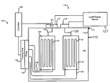
Referring now to FIG. 1, a thermal control system 100 for an electrical energy storage device or an electrochemical energy generation device 110 is depicted. Electrical energy storage device or electrochemical energy generation device 110 may include, but is not limited to any of a variety of batteries or electrochemical cells such as, but not limited to lithium based batteries, lithium ion batteries, lithium ion nano phosphate batteries, lithium sulfur batteries, lithium ion polymer batteries, sodium sulfur batteries, etc. In fact, such thermal control technology could be applied to any typical type of electro-chemical cell in existence today or to be developed. Further, other types of electrical energy storage devices may be used in place of battery 110 such as, capacitor devices including, but not limited to capacitive storage devices, inductive storage devices, electrolytic capacitors, hyper capacitors (as described in U.S. Published Patent Application No. 2004/0071944 and U.S. Pat. No. 7,428,137 both of which are herein incorporated by reference), polyvinylidene fluoride (PVDF) based capacitors carbon nanotube based capacitors, other conductive polymer based capacitors, carbon aerogel based capacitors, etc. Further still, energy storage or electrochemical energy generation device 110 may be representative of a fuel cell (as described in U.S. Published Patent Application No. 2009/0068521 which is herein incorporated by reference), or other electrochemical energy generation devices which may be known, or developed.
Electrical energy storage device or electrochemical energy generation device 110 includes a housing 112 having a housing wall with an interior wall surface 114 and exterior wall surface 113. Interior wall surface 114 of housing 112 may be filled with an electrolyte 124 or other material depending on the structure of either the electrical energy storage device or the electrochemical energy generation device 110. Electrical energy storage device or electrochemical energy generation device 110 may include, a cathode 120 coupled to a positive terminal 127 by a conductor 126. In an exemplary embodiment, load 121 may include a number of microchannel structures 132. Microchannel structures 132 may be integrated into cathode 120 or alternatively may be overlaid or coupled to cathode 120 such that heat emanating from cathode 120 may be collected by the microchannel structures 132. Such microchannel structures 132 may be formed by any of a variety of methods including etching, micromachining, and the like. Various materials for forming cathode 120 may be used, as is well known in the art depending on the type of electrical energy storage device or electrochemical energy generation device 110. A fluid connection 136 is coupled to microchannels 132. Fluid connections 136 are coupled to a thermal sink 138 through a pump 140. Such a thermal sink 138 may be a radiator or other form of heatsink. A pump 140 may also be coupled to a fluid circuit 136 in order to move fluid through microchannels 132. In one embodiment, a pump is used. In alternative embodiments, the fluid may be moved by osmotic pressure or the like without use of a pump 140. Similar to cathode 120, an anode 122 is electrically coupled to a negative terminal 129 of electrical energy storage device or electrochemical energy generation device 110 by a conductor 128. Similar to cathode 120, anode 122 may also include a microchannel structure 130 integrated into, overlaid, or coupled to anode 122. Microchannel structure 130 is fluidly coupled, by a fluid connection 134, to thermal sink 138 in much the same way that fluid connection 136 is coupled to thermal sink 138.
In an exemplary embodiment, a load or a charge source 121 is electrically coupled to positive terminal 127 and negative terminal 129 of electrical energy storage device or electrochemical energy generation device 110. Load 121 may be any of a variety of possible devices using energy from electrical energy storage device or electrochemical energy generation device 110. Charge source 121 may be any type of charging device that is used to charge electrical energy storage device 110. During charging, or during discharging by use of a load, large amounts of heat may be generated within electrical energy storage device or electrochemical energy generation device 110. Accordingly, it may be advantageous to use a microchannel thermal control system as described. In one exemplary embodiment, a controller 160 may be coupled to pump 140. Controller 160 may be any of a variety of controllers control devices, etc. for controlling the speed of pump 140. For example, pump 140 may be coupled to a sensor 162 which detects characteristics of electrical energy storage device or electrochemical energy generation device 110. Sensor 162 may be located at any of a variety of locations associated with electrical energy storage device or electrochemical energy generation device 110. Alternatively, controller 160 may be coupled to load or charge source 121 to detect characteristics of the usage of load or charge source 121. Controller 160 may be used to control pump 140 based on a variety of factors including, but not limited to a current draw, a current discharge, voltage, various states of the device using energy from electrical energy storage device or electrochemical energy generation device 110, or variable various states of a vehicle using electrical energy storage device or electrochemical energy generation device 110, or further states of the charge source 121.
In accordance with an exemplary embodiment, it may be desirable to cool the electrical energy storage device or the electrochemical energy generation device in anticipation of a heat generating event, such as discharge or energy demand or charging. By cooling in advance of the heat generating event, the thermal control system may be better enabled to keep up with the cooling demands. It is in a sense a “head start” for the cooling system. In an exemplary embodiment the “head start” may be determined by a processor which may be enabled with programming to monitor systems and make determinations as to when energy may be demanded or charging may occur. In other exemplary embodiments, the “head start” may be done in accordance with a schedule or in accordance with other preset or predetermined times.
Referring now to FIG. 2, a perspective cross-section of an exemplary cathode 120 is depicted. The cross section of FIG. 2 depicts microchannels 132 built into or integrated into cathode 120. Microchannels 132 are sealed fluid conduits having a top portion 133 shown partially cut-away. Microchannels 132 are not shown in a scaled depiction because microchannels 132 conventionally are of extremely small width, on the order of, but not limited to the width of a human hair. The height of microchannels 132 may be much greater than the width to achieve efficient laminar flow thermal control. The high aspect ratio of the microchannels increases the total surface area of the microchannel structures touching the fluid flow. The width of the microchannels 132 may be on the order of 10 μm, but is not limited thereto. FIG. 2 depicts a single configuration of microchannels 132 in which the microchannels are arranged side-by-side and fluid may flow through all the microchannels in parallel or may flow in a serial manner back and forth (serpentine) through each of the microchannels to complete a fluid circuit. Many other configurations of microchannels may also be conceived without departing from the scope of the disclosure and of the invention as claimed herein.
Referring now to FIG. 17, an alternative configuration of a microchannel thermal control system 1700 includes more than one of substrates 1710 which support microchannels 1720. Substrates 1710 may be integrated into or otherwise coupled to any of the electrical energy storage device or electrochemical energy generation device components as discussed. Microchannels 1720 may be of a parallel or any other configuration in which fluid may flow from an inlet manifold 1730 to an outlet manifold 1740. Such flow may proceed through any of the more than one sets of microchannels through microchannel inlets 1750 and through microchannel outlets 1760. In yet another configuration each of the sets of microchannels may include one or more interconnections 1770 and 1780 between the sets of microchannels. Providing such a structure has many advantages including, but not limited to performance characteristics, manufacturing characteristics, and application characteristics, as desired.
In one exemplary embodiment, electrical energy storage device or electrochemical energy generation device 110 is an electrical energy storage device that has a housing 112. The housing may have an external and internal surface, the internal surface being depicted as surface 114. Many components reside within the housing including, in some instances, the anode 122 and the cathode 120. Further, other chemicals or materials may also reside within the housing including an electrolyte 124, or other materials or chemicals as needed to generate electricity or to store energy. In one exemplary embodiment a plurality of microchannels is coupled to at least one of the internal surface 114 of the housing or at least one of the internal components such as, but not limited to cathode 120 and anode 122. A thermal sink 138 is coupled to the microchannels fluid connection 136. The thermal sink 138 is configured to transfer heat to or from fluid flowing through microchannels 132. In one exemplary embodiment, microchannels may be formed in a portion of a wall of the housing 114. Also, microchannels may be formed in a portion of any of the components residing within housing 112. In another exemplary embodiment, microchannels may be formed in a portion of a catalyst which may be disposed within housing 112. Further still, microchannels may be formed in electrical contacts, a current carrying conductor, a dielectric, etc. Also, microchannels may be formed integrally to any of these components or housings, or may be overlaid or disposed on or coupled to any of these components or housings. It may be advantageous to couple the microchannels to areas or components where the most heat is generated or collects.
In an exemplary embodiment, the fluid flowing through microchannels 132 may include any of a variety of fluids. Such fluids may include air, gas, water, antifreeze, molten salt, molten metal, micro-particles, liquid droplets, solid particles, etc. (see e.g. US 2006/0231233). Also, in an exemplary embodiment, the fluid may be at least partially circulated by any of a variety of devices including, a pump, a mechanical pump, electromagnetic (MHD) pump, electroosmotic pump, etc. The fluid may be circulated in any of a variety of ways including, by convection, by electroosmosis, etc. Further, in accordance with an exemplary embodiment, the electrical energy storage device may include one or more electrochemical cells, capacitive storage devices, inductive storage devices, electrolytic capacitors, supercapacitors, hypercapacitors, polyvinylidpue fluoride (PVDF) based capacitors, and various batteries, including, but not limited to lithium based batteries, lithium batteries, lithium ion batteries, lithium ion nanophosphate batteries, lithium sulfur batteries, lithium ion polymer batteries, etc.
In accordance with another exemplary embodiment, electrical energy storage device or electrochemical energy generation device 110 is a fuel cell. The fuel cell may include a housing having an external surface and an internal surface 114. At least one component resides within the housing. At least one component is configured to generate electrical power in combination with at least one other components, chemicals, or materials residing within the housing. In one embodiment, such components may include, but are not limited to cathode 120 and anode 122. A plurality of microchannels 132 may be coupled to the least one of the internal surface of the housing or the at least one internal components. A thermal sink 138, is coupled to the microchannels. Thermal sink 138 is configured to transfer heat to or from fluid flowing through the microchannels. In one exemplary embodiment, the microchannels are formed in a portion of a wall of the housing or at least one component residing within the housing. Similar to the electrical energy storage device configuration, many of the same components may reside within the housing and may include microchannels. Further, any other components which may be unique to a fuel cell, compared to the electrical energy storage device depicted in FIG. 1, may also include microchannels to cool such components.
Referring now to FIG. 3, a process 300 is depicted for controlling temperature of an electrical energy storage device or electrochemical energy generation device. Process 300 includes providing an electrical energy storage device or an electrochemical energy generation device with a housing (process 310). Process 300 also includes coupling an electrical energy storage device or electrochemical energy generation device components within the housing (process 320). Microchannels are formed in a surface of the electrical energy storage device or the electrochemical energy generation device components (process 330). A fluid is then flowed through the microchannels to provide thermal control to the components and to the overall electrical energy storage device or electrochemical energy generation device (process 340).
Referring now to FIG. 4, a process 400 of using electrical energy storage device or an electrochemical energy generation device is depicted. Process 400 includes coupling a load to draw current from the electrical energy storage device or the electrochemical energy generation device (process 410). The electrical energy storage device or the electrochemical energy generation device has a housing with an external surface and an internal surface. Process 400 also includes generating electricity by the electrical energy storage device or the electrochemical energy generation device using at least one component within the housing. The least one component is configured to generate electrical energy in combination with other components, chemicals, or materials residing within the housing (process 420). The electrical energy storage device is then cooled by transferring heat to fluid flowing through the microchannels coupled to at least one of the internal surface of the housing or at least one of the components (process 430). Heat is then rejected from the thermal sink that is coupled to the microchannels. The thermal sink is configured to transfer heat energy from the microchannels and is configured to receive a fluid flowing through the microchannels (process 440).
In accordance with another exemplary embodiment, a process of providing power for an electrical energy storage device or an electrochemical energy generation device includes providing an electrical energy storage device or an electrochemical energy generation device having a housing and including internal components within the housing. The process also includes providing a microchannel fluid thermal control system integrated into at least one of the interior of the housing or the internal components. Further, the process includes configuring the electrical energy storage device or electrochemical energy generation device for a platform for at least partially discharging the electrical energy storage device or the electrochemical energy generation device and using electrical energy from the electrical energy storage device.
In accordance with yet another exemplary embodiment, a process of providing power from an electrical energy storage device or an electrochemical energy generation device includes receiving the electrical energy storage device or the electrochemical energy generation device housing and including internal components within the housing. The process also includes receiving a microchannel fluid thermal control system integrated into at least one of the interior of the housing or the internal components. Further, the process includes discharging power at least partially from the electrical energy storage device or the electrochemical energy generation device. The electrical energy storage device or the electrochemical energy generation device is configured for a platform for discharging the electrical energy storage device or the electrochemical energy generation device and using the electrical energy from the electrical energy storage device.
Another exemplary process includes charging an electrical energy storage device. The electrical energy storage device is configured to receive electrical current to charge the electrical energy storage device. The electrical energy storage device includes a housing having an external surface and an internal surface. The process for charging the electrical energy storage device also may include configuring at least one component within the housing. The least one component being configured to generate electrical energy during a discharge phase in combination with other complements, chemicals, or materials residing within the housing. At least one component is configured to receive electrical charge during a charge phase. The exemplary process also includes providing a plurality of microchannels coupled to a least one out of the internal surface of the housing or the least one internal components to receive a heat generated during the charge phase and providing a fluid within the microchannels. A thermal sink is also provided to collect heat from the fluid coupled to the microchannels. The thermal sink is configured to transfer heat energy to or from the fluid flowing through the microchannels and the thermal sink.
A method of charging a electrical energy storage device also includes placing the electrical energy storage device to draw current from a charging source. The electrical energy storage device includes a housing having an external surface and an internal surface. The process includes receiving electricity by at least one component within the housing. At least one component is configured to receive electrical energy in combination with other components chemicals, or materials residing within the housing. The process also includes thermal control of the electrical energy storage device by transferring heat to a plurality of microchannels coupled to a least one of the internal surface of the housing or the at least one internal components. Further, the process includes transferring collected heat through the thermal sink coupled to the microchannels. The thermal sink is configured to transfer heat energy to or from the microchannels and receive a fluid through the microchannels in the thermal sink.
Further still, a method of charging an electrical energy storage device is disclosed. The method includes receiving the electrical energy storage device including a housing and including internal components within the housing. The process also includes integrating a microchannel fluid thermal control system into at least one of the interior housing or the internal components. Further, the method includes receiving current by the electrical energy storage device, from a charging source.
Referring now to FIG. 5, a process 500 for thermal control of an electrical energy storage device during discharge is depicted. Process 500 includes providing an electrical energy storage device (process 510). Process 500 also includes integrating a microchannel fluid thermal control system into the interior of the electrical energy storage device (process 520). Process 500 further includes configuring the electrical energy storage device for discharging electricity (process 530).
Referring now to FIG. 6, a process for discharging power from a power from an electrical energy storage device or an electrochemical energy generation device is depicted process 600 includes receiving an electrical energy storage device or an electrochemical energy generation device (process 610). Process 600 also includes receiving a microchannel fluid thermal control system that is integrated into the interior of the electrical energy storage device or the electrochemical energy generation device (process 620). Further, process 600 includes discharging power from the electrical energy storage device or the electrochemical energy generation device to a load using the stored or generated electrical energy (process 630). Using the microchannel thermal control system heat is then discharged from the electrical energy storage device or electrochemical energy generation device (process 640).
Referring now to FIG. 7, a process 700 for thermal control of an electrical energy storage device while charging is depicted. Process 700 includes configuring an electrical energy storage device to receive electrical charge current (process 710). The charge current is used to charge the electrical energy storage device, the electrical energy storage device capable of receiving a high power density current thereby causing heating of the electrical energy storage device and components of the electrical energy storage device. Process 700 also includes configuring interior components of the electrical energy storage device to generate electricity (process 720). Further, process 700 includes providing a plurality of microchannels into the interior of a housing of the electrical energy storage device (process 730). The interior of the housing may include interior surfaces of the housing as well as components within the housing. Further still, process 700 includes providing a radiative structure or a thermal sink that is used to collect heat from the fluids flowing through the microchannels (process 740).
Referring now to FIG. 8, a process 800 is depicted for thermal control of an electrical energy storage device during charging. Process 800 includes placing the electrical energy storage device in a situation to draw current from a charging source (process 810). Process 800 also includes receiving electricity by at least one component of the electrical energy storage device (process 820). Because heat is generated within the electrical energy storage device during the charging process, process 800 also includes thermal control of the electrical energy storage device by transferring heat to microchannels which are configured within housing of the electrical energy storage device (process 830). Heat is then rejected via a radiator or other thermal sink structure from the microchannels by transferring heat from the microchannel to the fluid flowing through the microchannels and to the thermal sink (process 840).
Referring now to FIG. 9, a process 900 is depicted for thermal control of an electrical energy storage device during charging. Process 900 includes receiving an electrical energy storage device in a situation whereby the electrical energy storage device may be charged (process 910). Process 900 also includes receiving a microchannel fluid thermal control system is integrated into the electrical energy storage device (process 920). Such a microchannel fluid thermal control system that may be one that is applied directly to components within the housing of the electrical energy storage device or may be one that is integrated into the housing of the electrical energy storage device or components within the housing of the electrical energy storage device. Process 900 also includes receiving current by the electrical energy storage device from the charging source (process 930).
Referring now to FIG. 10, a system 1000 for thermal control of an electrical energy storage device or an electrochemical energy generation device is depicted. Electrical energy storage device or electrochemical energy generation device 1000 may include a housing 1010 having an outer surface 1012 and an inner surface 1014. Within housing 1010 may be a plurality of components, chemicals, materials, etc. For example, a cathode 1020 may be coupled to a positive terminal 1027 by a conductive connection 1026. Cathode 1020 may have a surface 1022. Surface 1022 may be overlaid with or be integrated into cathode 1020 a high thermal conductivity material 1023 that is in thermal communication with the fluid circuit 1036. High thermal conductivity material 1023 may have a high k-value. The high k-value may be greater than approximately 410 W/(m*K). Fluid circuit 1036 may be used to circulate fluid to conduct heat away from cathode 1020 via the high thermal conductivity of the material 1023. In electrical energy storage devices and electrochemical energy generation devices that are charged or discharged rapidly or that manage a high power density, efficient thermal control is needed to maintain desired temperature. The use of high thermal conductivity materials as applied, allows efficient rejection of heat to maintain desired temperatures. Thermal circuit 1036 is coupled to a thermal sink 1038 and optionally through a pump, 1040. Pump 1040 helps move fluid through circuit 1036. Similarly, an anode 1030 may reside within housing 1010 having a high thermal conductivity material 1033 coupled to or integrated into surface 1032. A fluid circuit 1034 is in thermal communication with material 1033. Fluid circuit 1034 is coupled to thermal sink 1038 optionally through a pump 1040. Anode 1030 is electrically coupled to a negative terminal 1029 through conductive connection 1028. Positive terminal 1027 and negative terminal 1029 may be coupled to a load or charge source 1070. In an exemplary embodiment a controller 1060 may be coupled to any of a variety of mechanisms within system 1000 including, but not limited to, pump 1040 for controlling the rate of fluid flow within circuits 1036 and 1038, for example. Controller 1060 may be coupled to any of a variety of sensors including, but not limited to a current sensor 1062 which may be in a variety of locations including, but not limited to at terminal 1027. Many other types of sensors may also be used including, but not limited to temperature sensors, voltage sensors, flow sensors, chemical concentration sensors, and the like. The use of high thermal conductivity materials to aid the rejection of heat within the interior of an electrical energy storage device or an electrochemical energy generation device may be beneficial to provide adequate thermal control of such devices during rapid charging or rapid discharging, etc.
In various exemplary embodiments, the electrical energy storage device or the electrochemical energy generation device includes high thermal conductivity materials which include but are not limited to diamond and diamond based materials, diamond films, diamond composites (such as diamond-loaded copper or diamond-loaded aluminum), carbon fibers (including graphite fiber composites, as may exist in combination with materials in a matrix such as aluminum, Silicon Carbide (SiC), or various polymers), carbon-carbon materials (such as carbon fibers in a carbon matrix), carbon nanotubes, carbon aerogels and the like. Further, the high thermal conductivity materials may be formed into micro heat pipes, and other structures which will be beneficial to increase thermal conductivity. Such materials are exemplified in the following references: (1) “Applications for ultrahigh thermal conductivity graphite fibers,” T. F. Fleming, W. C. Riley, Proc. SPIE, Vol. 1997, 136 (1993) DOI:10.1117/12.163796, Online Publication Date: 14 Jan. 2005; “Vapor grown carbon fiber reinforced aluminum composites with very high thermal conductivity,” Jyh-Ming Ting, Max L. Lake J. Mater. Res. V. 10 #2 pp. 247-250 DOI: 10.1557/JMR.1995.0247 and (2) “New low-CTE ultrahigh-thermal-conductivity materials for lidar laser diode packaging,” C. Zweben Proc. SPIE, Vol. 5887, 58870D (2005) DOI: 10.1117/12.620175.
Referring now to FIG. 11, a method 1100 of thermal control of an electrical energy storage device or an electrochemical energy generation device is depicted. The method includes providing a housing which may have an external surface and an internal surface (process 1110). The method also includes coupling at least one component within the housing. At least one component is configured to generate electrical power in combination with other components, chemicals, or materials which may be residing within the housing (process 1120). Further, the method includes forming a plurality of thermal control structures of a high thermal conductivity material which is coupled to at least one of the internal surface of the housing or the least one internal components. The high thermal conductive material may have a high k-value, the high k-value being greater than approximately 410 W/(m*K) (process 1130). Further still, the method includes flowing a fluid adjacent the high thermal conductivity material to remove heat from the high thermal conductivity material (process 1140).
In another exemplary embodiment, the thermal sink may be formed at least partially of a high thermal conductivity material as described above. Such a structure may be used in a method of thermal control of an electrical energy storage device or an electrochemical energy generation device. Such a method may include providing a housing having an external surface and an internal surface. The method may also include coupling at least one component within the housing, at least one component being configured to generate electrical power in combination with other components, chemicals, or materials residing within the housing. Further, the method of thermal control may include forming a plurality of thermal control structures coupled to at least one of the internal surface of the housing or the at least one internal components. The method further includes flowing a fluid adjacent a plurality of thermal control structures and transferring heat to or from a thermal sink. The thermal sink is formed at least partially of a high thermal conductive material having a high k-value. The high k-value may be greater than approximately 410 W/(m*K).
Referring now to FIG. 12, a process of thermal control of an electrical energy storage device or an electrochemical energy generation device 1200 is depicted. Process 1200 may include placing an electrical load to draw current from the electrical energy storage device or the electrochemical energy generation device (process 1210). Process 1200 may also include thermal control of the electrical energy storage device or electrochemical energy generation device by transferring heat to thermal control structures which are formed of a high k-value material (process 1220). Further, process 1200 includes flowing fluid adjacent the high k-value material to remove heat therefrom (process 1230).
Referring now to FIG. 13, a method 1300 for providing power from an electrical energy storage device or an electrochemical energy generation device includes providing the electrical energy storage device or the electrochemical energy generation device. The electrical energy storage device or the electrochemical energy generation device includes a housing and includes internal components within the housing (process 1310). Process 1300 also includes thermal control of the electrical energy storage device or the electrochemical energy generation device by transferring heat to thermal control structures which are formed of high k-value material (process 1320). Further, process 1300 includes flowing fluid adjacent the high k-value material (process 1330). Further still, process 1300 includes configuring the electrical energy storage device or the electrochemical energy generation device for a platform for discharging the electrical energy storage device or the electrochemical energy generation device (process 1340).
Referring now to FIG. 14, a method 1400 of providing power from an electrical energy storage device or an electrochemical energy generation device includes providing the electrical energy storage device or the electrochemical energy generation device with a housing and with internal components within the housing (process 1410). The method also includes thermal control of the electrical energy storage device or the electrochemical energy generation device by transferring heat to a plurality of thermal control of structures formed of high k-value material (process 1420). Further, the method includes flowing fluid adjacent the high k-value materials (process 1430). Further still, process 1400 includes configuring the electrical energy storage device or the electrochemical energy generation device for a platform for discharging the electrical energy storage device or the electrochemical energy generation device (process 1440) and using the electrical energy from the electrical energy storage device or the electrochemical energy generation device (process 1400).
Referring now to FIG. 15, a method 1500 of charging an electrical energy storage device may include configuring the electrical energy storage device to receive electrical current to charge the electrical energy storage device (process 1510). The electrical energy storage device may include a housing having an external surface and an internal surface. The method may also include configuring at least one component within the housing. The least one component is configured to generate electrical energy, during a discharge phase, in combination with other components chemicals or materials residing within housing and at least one component configured to receive electrical charge during a charge phase (process 1520). A plurality of thermal control structures are provided of a high thermal conductivity material coupled to at least one of the internal surface of the housing or the least one internal components (process 1520). The high thermal conductivity material may have a high k-value the high k-value is greater than approximately 410 W/(m*K). The thermal conductivity material is configured to receive heat generated during the charge phase (process 1530). A thermal sink is provided to transfer heat to or from the fluid coupled to the high thermal conductivity material (process 1540). A thermal sink is configured to transfer heat energy to or from the fluid flowing through the high thermal conductivity material and the thermal sink.
Referring now to FIG. 16, a method 1600 of charging an electrical energy storage device includes placing the electrical energy storage device in a situation to draw charge current (process 1610). Process 1600 also includes thermal control of the electrical energy storage device by transferring heat to a plurality of thermal control structures formed of high thermal conductivity material and flowing fluid thereby (process 1620). Process 1600 also includes rejecting heat from the fluid through a radiative structure or a thermal sink (process 1630).
In another exemplary embodiment, structures, systems, and processes described above may also be applied to structures, systems, and processes which use microchannel thermal control for thermal control of electrical energy storage devices or electrochemical energy generation devices and base such thermal control on current (or other states of the electrical energy storage device or electrochemical energy generation device, such as (but not limited to voltage, power, temperature, charge state, etc.) that is either delivered to or from the electrical energy storage device or the electrochemical energy generation device. The current may be sensed by a variety of sensors and controlled by a pump that controls the rate of fluid flow using any of a variety of control algorithms and controllers. Such control algorithms may include but are not limited to classical control, feedback control, nonlinear control, adaptive control, etc. The control algorithms may also include state estimator's, adaptive control algorithms, Kalman filters, models of the electrical energy storage device or the electrochemical energy generation device. The pump may be controlled is any of a variety of ways including increased flow as current draw increase, flow may be increased linearly as current draw increase, flow may be decreased as current draw decreased, flow may be decreased nonlinearly as current draw decreases, flow may be increased linearly as current draw increases, flow may be decreased nonlinearly as current draw decreases, or flow may be increased nonlinearly as current draw increases and flow may be decreased linearly as current draw decreases. Further, other possibilities are equally applicable depending on the design specifications and desired responses.
In another exemplary embodiment, structures, systems, and processes described above may also be applied to structures, systems, and processes which use high thermal conductivity materials and for thermal control of electrical energy storage devices or electrochemical energy generation devices and base such thermal control on a state or states of a mobile device which the electrical energy storage device or electrochemical energy generation device is powering. The current may be sensed by a variety of sensors or by software which determines the state of the mobile device and a pump is controlled that controls the rate of fluid flow using any of a variety of control algorithms and controllers. Such control algorithms may include but are not limited to classical control, feedback control, nonlinear control, adaptive control, etc. The control algorithms may also include state estimator's, adaptive control algorithms, Kalman filters, models of the electrical energy storage device or the electrochemical energy generation device, etc.
The mobile device states on which fluid flow may be based may include any of a variety of states including but not limited to brightness, processing speed, processing demands, processor tasks, display brightness, hard disk state, hard disk speed, hard disk usage, wireless communication state, etc. Such a mobile device may include any of a variety of mobile electronic devices including, but not limited to, a computer, a laptop computer, a mobile phone, a global positioning system (GPS) unit, a power tool, etc. Further, other possibilities are equally applicable depending on the performance characteristics desired.
For example, in accordance with an exemplary embodiment, the mobile device may be a laptop computer having a battery pack that is cooled by a microchannel thermal control system. The microchannel thermal control system may include a pump or other device that controls the rate of fluid flow through the microchannels and thus the rate of thermal control. Because current demands may cause heating of the battery pack due to increased processing speed, increased processing tasks, increased hard disk speed, increased hard disk usage, etc. As discussed above, the demands for thermal control therefore increase. The control system is configured to detect or determine the state of the mobile device and make adjustments to the rate of thermal control by altering the rate of flow through the microchannel system thermal control based on mobile device states may be applied in the context of microchannel-based thermal control, high thermal conductivity material-based thermal control systems, and further microchannel and high thermal conductivity material thermal control systems.
The use of such a system in which control of fluid flow is based on mobile device states may be applied to a thermal control system which uses microchannels. Similarly, the system may be applied to an electrochemical energy generation device or electrical energy storage device that uses thermal and high thermal conduct to the materials in conjunction with a fluid thermal control system. Further, the control system described in which thermal control is based on mobile device states may also be applied to a system which uses a combination of microchannel thermal control and high thermal conductivity to the materials.
In another particular exemplary embodiment, the fluid thermal control system described above may be applied to electrical energy storage devices and energy to generation devices that are used in vehicle systems. In such a system a fluid pump may be coupled to a microchannel thermal control system of the electrical energy storage device or the electrochemical energy generation device. The electrical energy storage device or the electrochemical energy generation device may be configured to provide electrical energy to the drivetrain of the vehicle or in powering other equipment in the vehicle. A processor is configured to determine at least one of the states of the vehicle. A vehicle sensor may be coupled to the processor and may be configured to sense at least one vehicle characteristic. A controller is used with a control algorithm and maybe configured to control the functioning of the pump as a function of at least one vehicle state.
In accordance with an exemplary embodiment, the vehicle states may include but are not limited to engine speed, engine torque, engine acceleration, engine temperature, terrain grade, vehicle acceleration, vehicle speed, etc. Also, the concept and control system may be applied to any of a variety of vehicles including, but not limited to, a computer integrated into a vehicle, a truck, a boat, a bus, train, an automobile, etc. In other exemplary embodiments, a variety of sensors may be used including but not limited to current sensors, voltage sensors, temperature sensors, speed sensors, accelerometers, orientation sensors, attitude sensors, etc. The methods of applying thermal control based on vehicle states may be applied in the context of microchannel-based thermal control, high thermal conductivity material-based thermal control systems, and further microchannel and high thermal conductivity material thermal control systems.
In another exemplary embodiment, an electrical energy storage device or electrochemical energy generation device includes a housing having an external surface and an internal surface. Components may reside within the housing. The components are configured to generate electrical energy in combination with at least one of other components, chemicals, or materials residing within the housing. A plurality of microchannels may be fashioned to at least one of the internal surface of the housing or the at least one internal components. The plurality of microchannels may be divided into at least two sets of microchannels although any number of sets may be used. The two sets, for example, may be separated by at least one valve. A controller is configured to provide control signals to the valve. The valve may be configured to control fluid flow in at least two sets of microchannel such that fluid could flow through either set of microchannels or both sets simultaneously. The control signals are based on thermal control demand. For example, the thermal control demand may be of the overall system, or the thermal control demand may be localized. A thermal sink is coupled to the microchannels. The thermal sink is configured to transfer heat energy to or from the microchannel surfaces via the fluid flowing through the microchannel and the sinks. In such an embodiment, the thermal control demands may be met by controlling the action of opening or closing of the valves such that fluid may selectively flow through various sets of microchannel to provide needed localized thermal control.
The foregoing detailed description has set forth various embodiments of the devices and/or processes via the use of block diagrams, flowcharts, and/or examples. Insofar as such block diagrams, flowcharts, and/or examples contain one or more functions and/or operations, it will be understood by those within the art that each function and/or operation within such block diagrams, flowcharts, or examples can be implemented, individually and/or collectively, by a wide range of hardware, software, firmware, or virtually any combination thereof. In one embodiment, several portions of the subject matter described herein may be implemented via Application Specific Integrated Circuits (ASICs), Field Programmable Gate Arrays (FPGAs), digital signal processors (DSPs), or other integrated formats. However, those skilled in the art will recognize that some aspects of the embodiments disclosed herein, in whole or in part, can be equivalently implemented in integrated circuits, as one or more computer programs running on one or more computers (e.g., as one or more programs running on one or more computer systems), as one or more programs running on one or more processors (e.g., as one or more programs running on one or more microprocessors), as firmware, or as virtually any combination thereof, and that designing the circuitry and/or writing the code for the software and or firmware would be well within the skill of one of skill in the art in light of this disclosure. In addition, those skilled in the art will appreciate that the mechanisms of the subject matter described herein are capable of being distributed as a program product in a variety of forms, and that an illustrative embodiment of the subject matter described herein applies regardless of the particular type of signal bearing medium used to actually carry out the distribution. Examples of a signal bearing medium include, but are not limited to, the following: a recordable type medium such as a floppy disk, a hard disk drive, a Compact Disc (CD), a Digital Video Disk (DVD), a digital tape, a computer memory, etc.; and a transmission type medium such as a digital and/or an analog communication medium (e.g., a fiber optic cable, a waveguide, a wired communications link, a wireless communication link, etc.). Further, those skilled in the art will recognize that the mechanical structures disclosed are exemplary structures and many other forms and materials may be employed in constructing such structures.
In a general sense, those skilled in the art will recognize that the various embodiments described herein can be implemented, individually and/or collectively, by various types of electromechanical systems having a wide range of electrical components such as hardware, software, firmware, or virtually any combination thereof; and a wide range of components that may impart mechanical force or motion such as rigid bodies, spring or torsional bodies, hydraulics, and electro-magnetically actuated devices, or virtually any combination thereof. Consequently, as used herein “electro-mechanical system” includes, but is not limited to, electrical circuitry operably coupled with a transducer (e.g., an actuator, a motor, a piezoelectric crystal, etc.), electrical circuitry having at least one discrete electrical circuit, electrical circuitry having at least one integrated circuit, electrical circuitry having at least one application specific integrated circuit, electrical circuitry forming a general purpose computing device configured by a computer program (e.g., a general purpose computer configured by a computer program which at least partially carries out processes and/or devices described herein, or a microprocessor configured by a computer program which at least partially carries out processes and/or devices described herein), electrical circuitry forming a memory device (e.g., forms of random access memory), electrical circuitry forming a communications device (e.g., a modem, communications switch, or optical-electrical equipment), and any non-electrical analog thereto, such as optical or other analogs. Those skilled in the art will also appreciate that examples of electromechanical systems include but are not limited to a variety of consumer electronics systems, as well as other systems such as motorized transport systems, factory automation systems, security systems, and communication/computing systems. Those skilled in the art will recognize that electro-mechanical as used herein is not necessarily limited to a system that has both electrical and mechanical actuation except as context may dictate otherwise.
In a general sense, those skilled in the art will recognize that the various aspects described herein which can be implemented, individually and/or collectively, by a wide range of hardware, software, firmware, or any combination thereof can be viewed as being composed of various types of “electrical circuitry.” Consequently, as used herein “electrical circuitry” includes, but is not limited to, electrical circuitry having at least one discrete electrical circuit, electrical circuitry having at least one integrated circuit, electrical circuitry having at least one application specific integrated circuit, electrical circuitry forming a general purpose computing device configured by a computer program (e.g., a general purpose computer configured by a computer program which at least partially carries out processes and/or devices described herein, or a microprocessor configured by a computer program which at least partially carries out processes and/or devices described herein), electrical circuitry forming a memory device (e.g., forms of random access memory), and/or electrical circuitry forming a communications device (e.g., a modem, communications switch, or optical-electrical equipment). Those having skill in the art will recognize that the subject matter described herein may be implemented in an analog or digital fashion or some combination thereof.
Those skilled in the art will recognize that it is common within the art to implement devices and/or processes and/or systems in the fashion(s) set forth herein, and thereafter use engineering and/or business practices to integrate such implemented devices and/or processes and/or systems into more comprehensive devices and/or processes and/or systems. That is, at least a portion of the devices and/or processes and/or systems described herein can be integrated into other devices and/or processes and/or systems via a reasonable amount of experimentation. Those having skill in the art will recognize that examples of such other devices and/or processes and/or systems might include—as appropriate to context and application—all or part of devices and/or processes and/or systems of (a) an air conveyance (e.g., an airplane, rocket, hovercraft, helicopter, etc.), (b) a ground conveyance (e.g., a car, truck, locomotive, tank, armored personnel carrier, etc.), (c) a building (e.g., a home, warehouse, office, etc.), (d) an appliance (e.g., a refrigerator, a washing machine, a dryer, etc.), (e) a communications system (e.g., a networked system, a telephone system, a Voice over IP system, etc.), (f) a business entity (e.g., an Internet Service Provider (ISP) entity such as Comcast Cable, Quest, Southwestern Bell, etc), or (g) a wired/wireless services entity such as Sprint, Cingular, Nextel, etc.), etc.
One skilled in the art will recognize that the herein described components (e.g., steps), devices, and objects and the discussion accompanying them are used as examples for the sake of conceptual clarity and that various configuration modifications are within the skill of those in the art. Consequently, as used herein, the specific exemplars set forth and the accompanying discussion are intended to be representative of their more general classes. In general, use of any specific exemplar herein is also intended to be representative of its class, and the non-inclusion of such specific components (e.g., steps), devices, and objects herein should not be taken as indicating that limitation is desired.
With respect to the use of substantially any plural and/or singular terms herein, those having skill in the art can translate from the plural to the singular and/or from the singular to the plural as is appropriate to the context and/or application. The various singular/plural permutations are not expressly set forth herein for sake of clarity.
The herein described subject matter sometimes illustrates different components contained within, or connected with, different other components. It is to be understood that such depicted architectures are merely exemplary, and that in fact many other architectures can be implemented which achieve the same functionality. In a conceptual sense, any arrangement of components to achieve the same functionality is effectively “associated” such that the desired functionality is achieved. Hence, any two components herein combined to achieve a particular functionality can be seen as “associated with” each other such that the desired functionality is achieved, irrespective of architectures or intermedial components. Likewise, any two components so associated can also be viewed as being “operably connected”, or “operably coupled”, to each other to achieve the desired functionality, and any two components capable of being so associated can also be viewed as being “operably couplable”, to each other to achieve the desired functionality. Specific examples of operably couplable include but are not limited to physically mateable and/or physically interacting components and/or wirelessly interactable and/or wirelessly interacting components and/or logically interacting and/or logically interactable components.
While particular aspects of the present subject matter described herein have been shown and described, it will be apparent to those skilled in the art that, based upon the teachings herein, changes and modifications may be made without departing from the subject matter described herein and its broader aspects and, therefore, the appended claims are to encompass within their scope all such changes and modifications as are within the true spirit and scope of the subject matter described herein. Furthermore, it is to be understood that the invention is defined by the appended claims. It will be understood by those within the art that, in general, terms used herein, and especially in the appended claims (e.g., bodies of the appended claims) are generally intended as “open” terms (e.g., the term “including” should be interpreted as “including but not limited to,” the term “having” should be interpreted as “having at least,” the term “includes” should be interpreted as “includes but is not limited to,” etc.). It will be further understood by those within the art that if a specific number of an introduced claim recitation is intended, such an intent will be explicitly recited in the claim, and in the absence of such recitation no such intent is present. For example, as an aid to understanding, the following appended claims may contain usage of the introductory phrases “at least one” and “one or more” to introduce claim recitations. However, the use of such phrases should not be construed to imply that the introduction of a claim recitation by the indefinite articles “a” or “an” limits any particular claim containing such introduced claim recitation to inventions containing only one such recitation, even when the same claim includes the introductory phrases “one or more” or “at least one” and indefinite articles such as “a” or “an” (e.g., “a” and/or “an” should typically be interpreted to mean “at least one” or “one or more”); the same holds true for the use of definite articles used to introduce claim recitations. In addition, even if a specific number of an introduced claim recitation is explicitly recited, those skilled in the art will recognize that such recitation should typically be interpreted to mean at least the recited number (e.g., the bare recitation of “two recitations,” without other modifiers, typically means at least two recitations, or two or more recitations). Furthermore, in those instances where a convention analogous to “at least one of A, B, and C, etc.” is used, in general such a construction is intended in the sense one having skill in the art would understand the convention (e.g., “a system having at least one of A, B, and C” would include but not be limited to systems that have A alone, B alone, C alone, A and B together, A and C together, B and C together, and/or A, B, and C together, etc.). In those instances where a convention analogous to “at least one of A, B, or C, etc.” is used, in general such a construction is intended in the sense one having skill in the art would understand the convention (e.g., “a system having at least one of A, B, or C” would include but not be limited to systems that have A alone, B alone, C alone, A and B together, A and C together, B and C together, and/or A, B, and C together, etc.). It will be further understood by those within the art that virtually any disjunctive word and/or phrase presenting two or more alternative terms, whether in the description, claims, or drawings, should be understood to contemplate the possibilities of including one of the terms, either of the terms, or both terms. For example, the phrase “A or B” will be understood to include the possibilities of “A” or “B” or “A and B.”
While various aspects and embodiments have been disclosed herein, other aspects and embodiments will be apparent to those skilled in the art. The various aspects and embodiments disclosed herein are for purposes of illustration and are not intended to be limiting, with the true scope and spirit being indicated by the following claims.

Claims (24)

The invention claimed is:
1. A method of operating an electrical energy storage device or an electrochemical energy generation device, comprising:
charging the electrical energy storage device or the electrochemical energy generation device;
placing an electrical load to draw current from the electrical energy storage device or the electrochemical energy generation device, the electrical energy storage device or the electrochemical energy generation device including a housing having an external surface and an internal surface;
generating electricity by a component within the housing, the component being configured to generate electrical energy in combination with other components, chemicals, or materials residing within the housing;
altering the temperature of the electrical energy storage device or the electrochemical energy generation device by transferring heat to a plurality of microchannels coupled to at least one of the internal surface of the housing or the component, wherein at least one microchannel of the plurality of microchannels is at least partially formed of or coated with a high thermal conductivity material; and
transferring the collected heat through a thermal sink coupled to the plurality of microchannels, the thermal sink being located outside of the housing and the thermal sink being configured to transfer heat energy to or from the plurality of microchannels and receive a fluid flowing through the microchannels;
wherein the plurality of microchannels are formed in a portion of the component, wherein the component is a cathode.
2. The method of claim 1, wherein the plurality of microchannels are at least partially formed in a portion of a wall of the housing.
3. The method of claim 1, wherein the plurality of microchannels are at least partially formed on the internal surface of the housing.
4. The method of claim 1, wherein the plurality of microchannels are at least partially formed on a surface of the component.
5. The method of claim 1, wherein the plurality of microchannels are configured to induce laminar flow of the fluid through at least a portion of the plurality of microchannels.
6. The method of claim 1, wherein the fluid is at least partially circulated by a mechanical pump.
7. The method of claim 1, wherein the fluid is at least partially circulated by an electromagnetic (MHD) pump.
8. The method of claim 1, wherein the fluid is at least partially circulated by an electro osmotic pump.
9. The method of claim 1, wherein the fluid is at least partially circulated by convection.
10. The method of claim 1, wherein the fluid is at least partially circulated by electroosmosis.
11. The method of claim 1, wherein the electrical energy storage device includes one or more electrochemical cells.
12. The method of claim 1, wherein the electrical energy storage device includes one or more capacitive storage device.
13. The method of claim 1, wherein the electrical energy storage device includes one or more inductive storage devices.
14. The method of claim 1, wherein the electrical energy storage device includes one or more electrolytic capacitors.
15. The method of claim 1, wherein the electrical energy storage device includes one or more super capacitors.
16. The method of claim 1, wherein the electrical energy storage device includes one or more hypercapacitors.
17. The method of claim 1, wherein the electrical energy storage device includes a polyvinylidene fluoride (PVDF) based capacitor.
18. The method of claim 1, wherein electrical energy storage device includes at least one of a lithium-based battery, a lithium battery, a lithium-ion nanophosphate battery, a lithium sulfur battery, or a lithium-ion polymer-battery.
19. The method of claim 1, wherein the electrical energy storage device includes a sodium sulfur battery.
20. The method of claim 1, wherein the high thermal conductivity material is disposed adjacent a portion of a wall of a housing of the electrical energy storage device or the electrochemical energy generation device.
21. The method of claim 1, wherein the high thermal conductivity material is disposed adjacent a portion of the component of the electrical energy storage device or the electrochemical energy generation device.
22. The method of claim 1, wherein the high thermal conductivity material is disposed adjacent an internal surface of a housing of the electrical energy storage device or the electrochemical energy generation device.
23. The method of claim 1, wherein the high thermal conductivity material is disposed adjacent a surface of the component of the electrical energy storage device or the electrochemical energy generation device.
24. The method of claim 1, wherein the thermal sink is a radiator.
US12/455,016 2009-05-26 2009-05-26 System and method of operating an electrical energy storage device or an electrochemical energy generation device, during charge or discharge using microchannels and high thermal conductivity materials Expired - Fee Related US9433128B2 (en)

Priority Applications (15)

Application Number Priority Date Filing Date Title
US12/455,015 US9093725B2 (en) 2009-05-26 2009-05-26 System for altering temperature of an electrical energy storage device or an electrochemical energy generation device using microchannels based on states of the device
US12/455,016 US9433128B2 (en) 2009-05-26 2009-05-26 System and method of operating an electrical energy storage device or an electrochemical energy generation device, during charge or discharge using microchannels and high thermal conductivity materials
US12/455,025 US20100304257A1 (en) 2009-05-26 2009-05-26 System and method of operating an electrical energy storage device or an electrochemical energy generation device using microchannels and high thermal conductivity materials
US12/455,020 US8080326B2 (en) 2009-05-26 2009-05-26 Method of operating an electrical energy storage device using microchannels during charge and discharge
US12/455,034 US9065159B2 (en) 2009-05-26 2009-05-26 System and method of altering temperature of an electrical energy storage device or an electrochemical energy generation device using microchannels
KR1020117031070A KR20120060787A (en) 2009-05-26 2010-05-26 System and method of altering temperature of an electrical energy storage device or an electrochemical energy generation device using microchannels
JP2012513055A JP5754031B2 (en) 2009-05-26 2010-05-26 System for changing the temperature of an electrical energy storage device or electrochemical energy generator using a high thermal conductivity material
KR1020117031072A KR101749298B1 (en) 2009-05-26 2010-05-26 System and method of altering temperature of an electrical energy storage device or an electrochemical energy generation device using high thermal conductivity materials
PCT/US2010/001563 WO2010138196A1 (en) 2009-05-26 2010-05-26 System and method of altering temperature of an electrical energy storage device or an electrochemical energy generation device using microchannels
JP2012513054A JP2012528458A (en) 2009-05-26 2010-05-26 System and method for changing the temperature of an electrical energy storage device or electrochemical energy generation device using a microchannel
EP10780938.6A EP2436077A4 (en) 2009-05-26 2010-05-26 System and method of altering temperature of an electrical energy storage device or an electrochemical energy generation device using high thermal conductivity materials
PCT/US2010/001564 WO2010138197A1 (en) 2009-05-26 2010-05-26 System and method of altering temperature of an electrical energy storage device or an electrochemical energy generation device using high thermal conductivity materials
CN2010800330730A CN102460806A (en) 2009-05-26 2010-05-26 System and method of altering temperature of an electrical energy storage device or an electrochemical energy generation device using microchannels
CN201080033078.3A CN102460807B (en) 2009-05-26 2010-05-26 For using high thermal conductivity materials to change the system and method for the temperature of apparatus for storing electrical energy or electrochemical energy generation device
EP10780937.8A EP2436076B1 (en) 2009-05-26 2010-05-26 System and method of altering temperature of an electrical energy storage device or an electrochemical energy generation device using microchannels

Applications Claiming Priority (10)

Application Number Priority Date Filing Date Title
US12/455,016 US9433128B2 (en) 2009-05-26 2009-05-26 System and method of operating an electrical energy storage device or an electrochemical energy generation device, during charge or discharge using microchannels and high thermal conductivity materials
US12/455,023 US8802266B2 (en) 2009-05-26 2009-05-26 System for operating an electrical energy storage device or an electrochemical energy generation device using microchannels based on mobile device states and vehicle states
US12/455,019 US8101293B2 (en) 2009-05-26 2009-05-26 System for altering temperature of an electrical energy storage device or an electrochemical energy generation device using high thermal conductivity materials based on states of the device
US12/455,020 US8080326B2 (en) 2009-05-26 2009-05-26 Method of operating an electrical energy storage device using microchannels during charge and discharge
US12/455,036 US20100304259A1 (en) 2009-05-26 2009-05-26 Method of operating an electrical energy storage device or an electrochemical energy generation device using high thermal conductivity materials during charge and discharge
US12/455,037 US8715875B2 (en) 2009-05-26 2009-05-26 System and method of operating an electrical energy storage device or an electrochemical energy generation device using thermal conductivity materials based on mobile device states and vehicle states
US12/455,015 US9093725B2 (en) 2009-05-26 2009-05-26 System for altering temperature of an electrical energy storage device or an electrochemical energy generation device using microchannels based on states of the device
US12/455,034 US9065159B2 (en) 2009-05-26 2009-05-26 System and method of altering temperature of an electrical energy storage device or an electrochemical energy generation device using microchannels
US12/455,031 US20100304258A1 (en) 2009-05-26 2009-05-26 System and method of altering temperature of an electrical energy storage device or an electrochemical energy generation device using high thermal conductivity materials
US12/455,025 US20100304257A1 (en) 2009-05-26 2009-05-26 System and method of operating an electrical energy storage device or an electrochemical energy generation device using microchannels and high thermal conductivity materials

Related Parent Applications (3)

Application Number Title Priority Date Filing Date
US12/455,025 Continuation-In-Part US20100304257A1 (en) 2009-05-26 2009-05-26 System and method of operating an electrical energy storage device or an electrochemical energy generation device using microchannels and high thermal conductivity materials
US12/455,034 Continuation-In-Part US9065159B2 (en) 2009-05-26 2009-05-26 System and method of altering temperature of an electrical energy storage device or an electrochemical energy generation device using microchannels
US12/455,015 Continuation-In-Part US9093725B2 (en) 2009-05-26 2009-05-26 System for altering temperature of an electrical energy storage device or an electrochemical energy generation device using microchannels based on states of the device

Related Child Applications (2)

Application Number Title Priority Date Filing Date
US12/455,037 Continuation-In-Part US8715875B2 (en) 2009-05-26 2009-05-26 System and method of operating an electrical energy storage device or an electrochemical energy generation device using thermal conductivity materials based on mobile device states and vehicle states
US12/455,019 Continuation-In-Part US8101293B2 (en) 2009-05-26 2009-05-26 System for altering temperature of an electrical energy storage device or an electrochemical energy generation device using high thermal conductivity materials based on states of the device

Publications (2)

Publication Number Publication Date
US20100304255A1 US20100304255A1 (en) 2010-12-02
US9433128B2 true US9433128B2 (en) 2016-08-30

Family

ID=43220620

Family Applications (5)

Application Number Title Priority Date Filing Date
US12/455,020 Expired - Fee Related US8080326B2 (en) 2009-05-26 2009-05-26 Method of operating an electrical energy storage device using microchannels during charge and discharge
US12/455,025 Abandoned US20100304257A1 (en) 2009-05-26 2009-05-26 System and method of operating an electrical energy storage device or an electrochemical energy generation device using microchannels and high thermal conductivity materials
US12/455,016 Expired - Fee Related US9433128B2 (en) 2009-05-26 2009-05-26 System and method of operating an electrical energy storage device or an electrochemical energy generation device, during charge or discharge using microchannels and high thermal conductivity materials
US12/455,034 Expired - Fee Related US9065159B2 (en) 2009-05-26 2009-05-26 System and method of altering temperature of an electrical energy storage device or an electrochemical energy generation device using microchannels
US12/455,015 Expired - Fee Related US9093725B2 (en) 2009-05-26 2009-05-26 System for altering temperature of an electrical energy storage device or an electrochemical energy generation device using microchannels based on states of the device

Family Applications Before (2)

Application Number Title Priority Date Filing Date
US12/455,020 Expired - Fee Related US8080326B2 (en) 2009-05-26 2009-05-26 Method of operating an electrical energy storage device using microchannels during charge and discharge
US12/455,025 Abandoned US20100304257A1 (en) 2009-05-26 2009-05-26 System and method of operating an electrical energy storage device or an electrochemical energy generation device using microchannels and high thermal conductivity materials

Family Applications After (2)

Application Number Title Priority Date Filing Date
US12/455,034 Expired - Fee Related US9065159B2 (en) 2009-05-26 2009-05-26 System and method of altering temperature of an electrical energy storage device or an electrochemical energy generation device using microchannels
US12/455,015 Expired - Fee Related US9093725B2 (en) 2009-05-26 2009-05-26 System for altering temperature of an electrical energy storage device or an electrochemical energy generation device using microchannels based on states of the device

Country Status (6)

Country Link
US (5) US8080326B2 (en)
EP (2) EP2436077A4 (en)
JP (2) JP2012528458A (en)
KR (2) KR101749298B1 (en)
CN (2) CN102460807B (en)
WO (2) WO2010138196A1 (en)

Families Citing this family (51)

* Cited by examiner, † Cited by third party
Publication number Priority date Publication date Assignee Title
US8299761B2 (en) * 2008-12-29 2012-10-30 Interstellar Technologies Corporation Dense energy storage via interacting nanostructures
US20100304259A1 (en) * 2009-05-26 2010-12-02 Searete Llc. A Limited Liability Corporation Of The State Of Delaware Method of operating an electrical energy storage device or an electrochemical energy generation device using high thermal conductivity materials during charge and discharge
CN103813814A (en) 2011-05-05 2014-05-21 艾克西根特技术有限公司 Gel coupling for electrokinetic delivery system
JP2015501170A (en) * 2011-09-30 2015-01-15 エクシジェント テクノロジーズ, エルエルシー Electrokinetic pump wound treatment system and method
US9689624B2 (en) * 2011-11-18 2017-06-27 GM Global Technology Operations LLC Method for mitigating thermal propagation of batteries using heat pipes
US9647249B2 (en) 2012-01-17 2017-05-09 Ford Global Technologies, Llc Cooling system for vehicle batteries
EP2808934B1 (en) * 2012-01-24 2017-04-12 NGK Insulators, Ltd. Power storage apparatus and method of operating power storage apparatus
JP5974721B2 (en) * 2012-08-09 2016-08-23 株式会社豊田自動織機 Battery pack
US9090176B2 (en) 2012-10-01 2015-07-28 Fca Us Llc Method and device for electrochemical cell propagation avoidance in a battery module
JP6286438B2 (en) 2012-10-16 2018-02-28 アンブリ・インコーポレイテッド Electrochemical energy storage device and housing
US11387497B2 (en) 2012-10-18 2022-07-12 Ambri Inc. Electrochemical energy storage devices
US9735450B2 (en) 2012-10-18 2017-08-15 Ambri Inc. Electrochemical energy storage devices
US9520618B2 (en) 2013-02-12 2016-12-13 Ambri Inc. Electrochemical energy storage devices
US9312522B2 (en) 2012-10-18 2016-04-12 Ambri Inc. Electrochemical energy storage devices
US11721841B2 (en) 2012-10-18 2023-08-08 Ambri Inc. Electrochemical energy storage devices
US10541451B2 (en) 2012-10-18 2020-01-21 Ambri Inc. Electrochemical energy storage devices
US11211641B2 (en) 2012-10-18 2021-12-28 Ambri Inc. Electrochemical energy storage devices
US10270139B1 (en) 2013-03-14 2019-04-23 Ambri Inc. Systems and methods for recycling electrochemical energy storage devices
US9502737B2 (en) 2013-05-23 2016-11-22 Ambri Inc. Voltage-enhanced energy storage devices
US9799933B2 (en) * 2013-08-28 2017-10-24 Robert Bosch Gmbh Solid state battery with integrated rate booster
CN105830247B (en) 2013-10-16 2019-04-26 安保瑞公司 Sealing element for high-temperature reactivity material apparatus
WO2015095245A1 (en) * 2013-12-16 2015-06-25 KULR Technology Corporation Carbon fiber heat exchangers
TWI492437B (en) * 2014-04-08 2015-07-11 Go Tech Energy Co Ltd System for uniformly distributing temperature across batteries
FR3022401B1 (en) * 2014-06-12 2019-11-01 Psa Automobiles Sa. METHOD FOR CONTROLLING THE TEMPERATURE OF AN ELECTRIC UNIT OF A MOTOR VEHICLE
TWI509870B (en) * 2014-07-18 2015-11-21 Inst Nuclear Energy Res Atomic Energy Council Method of Charging and Discharging Power by Using Electrolyte Fluid Lines
US9742047B2 (en) 2014-08-11 2017-08-22 Milwaukee Electric Tool Corporation Battery pack with phase change material
AU2014408260B2 (en) * 2014-10-07 2020-12-17 Upstart Power Inc SCOFC-conduction
FR3030121B1 (en) * 2014-12-16 2017-01-20 Commissariat Energie Atomique LITHIUM ACCUMULATOR WITH THERMALLY INSULATED PACKAGING WITH TWO LAYERS AND HEAT TRANSDUCER FOR THERMAL MANAGEMENT
US10181800B1 (en) 2015-03-02 2019-01-15 Ambri Inc. Power conversion systems for energy storage devices
WO2016141354A2 (en) 2015-03-05 2016-09-09 Ambri Inc. Ceramic materials and seals for high temperature reactive material devices
US9893385B1 (en) 2015-04-23 2018-02-13 Ambri Inc. Battery management systems for energy storage devices
US10790523B2 (en) 2015-10-20 2020-09-29 Upstart Power, Inc. CPOX reactor control system and method
CA3040431C (en) * 2015-10-20 2023-02-28 Upstart Power, Inc. Fuel reformer system
CN105682428A (en) * 2016-03-28 2016-06-15 中国电子科技集团公司第二十九研究所 High-power chip heat radiation device manufacturing method
CN115566219A (en) 2016-08-11 2023-01-03 新兴电力公司 Planar solid oxide fuel cell unit, stack unit and system
US11929466B2 (en) 2016-09-07 2024-03-12 Ambri Inc. Electrochemical energy storage devices
AU2017340911B2 (en) * 2016-10-06 2023-06-15 Upstart Power, Inc. SOFC system formed with multiple thermally conductive pathways
US10998590B2 (en) * 2016-11-18 2021-05-04 Romeo Systems, Inc. Systems and methods for battery thermal management utilizing a vapor chamber
DE102017103271A1 (en) * 2017-02-17 2018-08-23 Benteler Automobiltechnik Gmbh Electrical charging arrangement and motor vehicle
CN110731027A (en) 2017-04-07 2020-01-24 安保瑞公司 Molten salt battery with solid metal cathode
GB2565131B (en) * 2017-08-04 2021-07-28 Ge Aviat Systems Ltd Modular power system and method of mitigating failure propagation between a plurality of modules in a modular power system
CN108615961B (en) * 2018-05-11 2020-02-07 西安交通大学 Echelon complementary electricity-heat balance electricity storage charging system and method
US10873116B2 (en) * 2018-05-18 2020-12-22 Lee Fei Chen Charging device having thermoelectric module
CN110608624B (en) * 2018-06-14 2023-03-28 舍弗勒技术股份两合公司 Heat exchange unit and heat exchange system for hybrid vehicle
CN109148927B (en) * 2018-09-04 2021-03-19 重庆大学 Air self-breathing membraneless microfluidic fuel cell with immersed microjets
DE102019101259A1 (en) * 2019-01-18 2020-07-23 Bayerische Motoren Werke Aktiengesellschaft Battery cell with temperature control, high-voltage battery and motor vehicle
DE202019101687U1 (en) * 2019-03-25 2020-06-26 Reinz-Dichtungs-Gmbh Temperature control plate with a microstructured liquid channel, especially for motor vehicles
CN113465178B (en) * 2020-07-23 2022-04-15 中北大学 Communication waste heat utilization heat pipe system
CN113078389B (en) * 2021-03-15 2021-11-16 深圳市朗泰沣电子有限公司 Micro-channel cold plate of power battery and preparation method thereof
CN113206319B (en) * 2021-04-27 2022-03-11 吉林大学 Fuzzy sliding mode optimization method for liquid cooling system of power battery pack of new energy automobile
WO2022255099A1 (en) * 2021-05-31 2022-12-08 日本碍子株式会社 Unit battery and module battery for high-temperature-operation secondary battery

Citations (104)

* Cited by examiner, † Cited by third party
Publication number Priority date Publication date Assignee Title
US3290176A (en) 1966-05-16 1966-12-06 Electric Storage Battery Co Electric storage battery electrolyte circulator device
US3901731A (en) 1971-02-15 1975-08-26 Alsthom Cgee Thin sheet apparatus for supplying and draining liquid
US4233369A (en) 1979-10-29 1980-11-11 United Technologies Corporation Fuel cell cooler assembly and edge seal means therefor
US4245009A (en) 1979-10-29 1981-01-13 United Technologies Corporation Porous coolant tube holder for fuel cell stack
US4403018A (en) 1980-05-31 1983-09-06 Electrochemische Energieconversie, N.V. Apparatus for supplying or draining a fluid to or from the marginal portion of a flat fuel cell electrode and an electrode element and a fuel cell provided with such an apparatus
US4505992A (en) 1983-04-11 1985-03-19 Engelhard Corporation Integral gas seal for fuel cell gas distribution assemblies and method of fabrication
US4541040A (en) 1983-11-21 1985-09-10 Doble Engineering Company Power converting
US4561040A (en) 1984-07-12 1985-12-24 Ibm Corporation Cooling system for VLSI circuit chips
GB2206726A (en) 1987-07-03 1989-01-11 Chloride Silent Power Ltd Batteries employing bus plates
US4804592A (en) 1987-10-16 1989-02-14 The United States Of America As Represented By The United States Department Of Energy Composite electrode for use in electrochemical cells
JPH01186768A (en) 1988-01-19 1989-07-26 Meidensha Corp Electrode structure of electrolyte circulation type secondary battery
US4973530A (en) 1989-12-21 1990-11-27 The United States Of America As Represented By The United States Department Of Energy Fuel cell water transport
US5009967A (en) 1989-10-24 1991-04-23 International Fuel Cells Corporation Fuel cell power plant fuel control
US5077637A (en) 1989-09-25 1991-12-31 The Charles Stark Draper Lab., Inc. Solid state directional thermal cable
US5077103A (en) 1990-06-25 1991-12-31 Rockwell International Corporation Refractory solid-state heat pipes and heat shields
US5230966A (en) 1991-09-26 1993-07-27 Ballard Power Systems Inc. Coolant flow field plate for electrochemical fuel cells
US5366819A (en) 1993-10-06 1994-11-22 Ceramatec, Inc. Thermally integrated reformer for solid oxide fuel cells
US5447805A (en) 1994-03-15 1995-09-05 Electric Fuel (E.F.L.) Ltd. Cell for a metal-air battery
US5549153A (en) 1992-11-13 1996-08-27 Behr Gmbh & Co. Device for cooling drive components and heating a passenger compartment of an electric vehicle
JPH0950821A (en) 1995-08-07 1997-02-18 Nissan Motor Co Ltd Battery module
US5663595A (en) 1994-08-03 1997-09-02 Sumitomo Electric Industries, Ltd. Diamond heat sink comprising synthetic diamond film
CN1184559A (en) 1995-05-17 1998-06-10 H动力公司 Plastic platelet fuel cells employing integrated fluid management
US5858567A (en) 1994-10-12 1999-01-12 H Power Corporation Fuel cells employing integrated fluid management platelet technology
US5880929A (en) 1997-12-01 1999-03-09 Intel Corporation Heat exchanger system for cooling a hinged computing device
US5909356A (en) 1996-09-13 1999-06-01 Tdk Corporation Solid state electric double layer capacitor
WO2001031053A1 (en) 1999-10-22 2001-05-03 Aclara Biosciences, Inc. Microfluidic card thermal control
US6265836B1 (en) 1998-03-13 2001-07-24 Sony Corporation Image distortion compensating apparatus
WO2001091208A2 (en) 2000-05-24 2001-11-29 Litech, L.L.C. Lithium-ion electrochemical cell and battery
US6440610B1 (en) 1999-12-10 2002-08-27 Samsung Sdi Co., Ltd. Negative active material for lithium secondary battery and manufacturing method of same
US6472095B2 (en) 2000-12-29 2002-10-29 Utc Fuel Cells, Llc Hybrid fuel cell reactant flow fields
US6503298B1 (en) 2001-04-30 2003-01-07 Battelle Memorial Institute Apparatus and methods for hydrogen separation/purification utilizing rapidly cycled thermal swing sorption
US20030062149A1 (en) 2001-09-28 2003-04-03 Goodson Kenneth E. Electroosmotic microchannel cooling system
US20030099883A1 (en) 2001-10-10 2003-05-29 Rosibel Ochoa Lithium-ion battery with electrodes including single wall carbon nanotubes
US20030118145A1 (en) 2000-05-12 2003-06-26 Faris Sadeg M Multiple chamber containment system
US20030186107A1 (en) 2002-03-04 2003-10-02 Maston Valerie A. High performance fuel cells
US20030207156A1 (en) 2000-10-13 2003-11-06 Ovshinsky Stanford R. Very low emission hybrid electric vehicle incorporating an integrated propulsion system including a fuel cell and a high power nickel metal hydride battery pack
US6653002B1 (en) 1997-05-09 2003-11-25 Ronald J. Parise Quick charge battery with thermal management
US6689500B2 (en) 2001-03-29 2004-02-10 Power Plug, Inc. Cooling a fuel cell stack
US20040071944A1 (en) 2001-04-12 2004-04-15 Weir Richard Dean Electrical-energy-storage unit (EESU) utilizing ceramic and integrated-circuit technologies for replacement of electrochemical batteries
US6749010B2 (en) 2002-06-28 2004-06-15 Advanced Energy Technology Inc. Composite heat sink with metal base and graphite fins
EP1445144A1 (en) 2002-11-28 2004-08-11 HONDA MOTOR CO., Ltd. Control apparatus for fuel cell vehicle
US20040194944A1 (en) 2002-09-17 2004-10-07 Hendricks Terry Joseph Carbon nanotube heat-exchange systems
US6821666B2 (en) 2001-09-28 2004-11-23 The Regents Of The Univerosity Of California Method of forming a package for mems-based fuel cell
US20040245235A1 (en) 2002-07-12 2004-12-09 Kazuhito Kishi Heating apparatus, auxiliary power supply apparatus, auxiliary power supply system, fixation apparatus, and moving picture formation apparatus
WO2005001959A2 (en) 2003-06-09 2005-01-06 Saint-Gobain Ceramics & Plastics, Inc. Stack supported solid oxide fuel cell
US20050069741A1 (en) 2003-09-26 2005-03-31 Yutaka Enokizu Fuel cell system
US20050079393A1 (en) 2003-10-14 2005-04-14 Hsi-Ming Shu Method and system for controlling constant temperature for fuel cells
US20050088823A1 (en) 2003-10-22 2005-04-28 Kabadi Ashok N. Variable density graphite foam heat sink
US20050092467A1 (en) 2003-10-31 2005-05-05 Hon Hai Precision Industry Co., Ltd. Heat pipe operating fluid, heat pipe, and method for manufacturing the heat pipe
US20050170241A1 (en) 2004-02-04 2005-08-04 Daimlerchrysler Ag Electrochemical energy store
WO2005080901A1 (en) 2004-02-24 2005-09-01 Spec Co., Ltd Micro heat exchanger for fuel cell and manufacturing method thereof
US20050202310A1 (en) 2003-10-03 2005-09-15 Yahnker Christopher R. Thermal management systems for battery packs
US20050221139A1 (en) 2004-03-15 2005-10-06 Hampden-Smith Mark J Modified carbon products, their use in bipolar plates and similar devices and methods relating to same
US20050250002A1 (en) 2004-04-28 2005-11-10 National Research Council Of Canada Composite catalyst layer, electrode and passive mixing flow field for compressionless fuel cells
US6976532B2 (en) 2003-06-26 2005-12-20 The Regents Of The University Of California Anisotropic thermal applications of composites of ceramics and carbon nanotubes
JP2006054456A (en) 2004-08-02 2006-02-23 Asml Holding Nv Method for compact micro channel laminated heat exchange, and its system
US20060088751A1 (en) 2002-03-05 2006-04-27 Manfred Stefener Mobile device for supplying power by means of fuel cells
US20060180300A1 (en) 2003-07-23 2006-08-17 Lenehan Daniel J Pump and fan control concepts in a cooling system
US20060179718A1 (en) 2003-05-16 2006-08-17 Whyatt Greg A Rapid start fuel reforming systems and techniques
US20060194095A1 (en) 2005-02-28 2006-08-31 Gayatri Vyas Method to make conductive hydrophilic fuel cell elements
US20060231233A1 (en) 2005-04-14 2006-10-19 Farid Mohammed M Microchannel heat exchanger with micro-encapsulated phase change material for high flux cooling
US20060234092A1 (en) 2005-04-14 2006-10-19 Thompson Eric L Method to begin coolant circulation to prevent MEA overheating during cold start
US20060246333A1 (en) 2005-04-27 2006-11-02 Schaevitz Samuel B Fuel cell apparatus and methods
US20060263665A1 (en) 2005-05-18 2006-11-23 Lilliputian Systems Inc. Fuel cell apparatus and methods
US7156159B2 (en) 2003-03-17 2007-01-02 Cooligy, Inc. Multi-level microchannel heat exchangers
US20070042667A1 (en) 2002-03-08 2007-02-22 Chien-Min Sung Diamond-like carbon energy conversion devices and methods thereof
US20070068714A1 (en) 2005-09-23 2007-03-29 Afs Trinity Power Corporation Method and apparatus for power electronics and control of plug-in hybrid propulsion with fast energy storage
KR20070048642A (en) 2004-01-28 2007-05-09 이노키, 칸지 Electrical rotary machine and electromagnetic apparatus
US7226675B2 (en) 2000-10-13 2007-06-05 Ovonic Battery Company, Inc. Very low emission hybrid electric vehicle incorporating an integrated propulsion system including a fuel cell and a high power nickel metal hydride battery pack
US20070160901A1 (en) 2001-07-13 2007-07-12 Inventex Corporation Cell structure for electrochemical devices and method of making same
US20070184320A1 (en) 2004-06-24 2007-08-09 Jean-Paul Domen Cooling devices for various applications
US7271567B2 (en) 2004-01-22 2007-09-18 Jadoo Power Systems, Inc. Fuel cell power and management system, and technique for controlling and/or operating same
JP2007266403A (en) 2006-03-29 2007-10-11 Nec Personal Products Co Ltd Cooling device for electronics equipment
US20070236287A1 (en) 2006-03-23 2007-10-11 Infineon Technologies Ag Switching converter with several converter stages
US20070248854A1 (en) 2006-03-30 2007-10-25 Casio Computer Co., Ltd. Power generation module, system, and method for driving the power generation module
WO2007125718A1 (en) 2006-04-27 2007-11-08 Kyocera Corporation Electronic device
US20070259229A1 (en) 2006-05-04 2007-11-08 Chun-Chin Tung Fuel cell activation method and the device thereof
US20070264546A1 (en) 2006-05-15 2007-11-15 Laven Arne Hydrogen-producing fuel cell systems with load-responsive feedstock delivery systems
CN101079502A (en) 2006-05-20 2007-11-28 日产自动车株式会社 Battery structure
US20070284095A1 (en) 2006-02-16 2007-12-13 Jinliang Wang Hybrid heat exchangers
US20070298316A1 (en) 2006-06-22 2007-12-27 Panasonic Ev Energy Co., Ltd. Battery cooling device, air flow control device, and computer readable medium
US20080007893A1 (en) 2005-01-11 2008-01-10 Seiji Takagi Solid Electrolytic Capacitor And Method For Manufacturing Same
US7326480B2 (en) 2000-05-17 2008-02-05 Relion, Inc. Fuel cell power system and method of controlling a fuel cell power system
US20080044725A1 (en) 2006-08-15 2008-02-21 Donald Sadoway High-amperage energy storage device and method
US7335437B2 (en) 2000-11-08 2008-02-26 Daimlerchrysler Ag Fuel cell stack
US20080059814A1 (en) 2006-08-31 2008-03-06 Ati Technologies Inc. Power source dependent program execution
US20080090114A1 (en) 2006-10-11 2008-04-17 Lilliputian Systems, Inc. Systems and methods for processing fuel for fuel cells
WO2008053213A1 (en) 2006-11-01 2008-05-08 Ceres Intellectual Property Company Limited Fuel cell heat exchange systems and methods
JP2008111653A (en) 2006-10-17 2008-05-15 Cooligy Inc Cooler
US7393369B2 (en) 2002-06-11 2008-07-01 Trulite, Inc. Apparatus, system, and method for generating hydrogen
US20080206608A1 (en) 2007-02-26 2008-08-28 Gm Global Technology Operations, Inc. Method for dynamic adaptive relative humidity control in the cathode of a fuel cell stack
US7428137B2 (en) 2004-12-03 2008-09-23 Dowgiallo Jr Edward J High performance capacitor with high dielectric constant material
US20090068521A1 (en) 2006-05-05 2009-03-12 Martin Buchinger Cooling System for a Fuel Cell
US20090130511A1 (en) 2007-11-19 2009-05-21 Microcell Corporation Fuel Cell Module
US7537851B2 (en) 2004-01-30 2009-05-26 Samsung Sdi Co., Ltd. Fuel cell system including separator having cooling water flow channels
US20090253001A1 (en) 2005-12-15 2009-10-08 Nissan Motor Co., Ltd. Fuel Cell System, Fuel Cell Vehicle, and Operating Method for Fuel Cell System
US7611792B2 (en) 1999-08-06 2009-11-03 Design Technology And Innovation Ltd. Humidifying gas induction or supply system
US7645530B2 (en) 2003-06-30 2010-01-12 Paul Scherrer Institute Method and apparatus for humidification of the membrane of a fuel cell
US7648786B2 (en) 2006-07-27 2010-01-19 Trulite, Inc System for generating electricity from a chemical hydride
US7651797B2 (en) 2002-01-14 2010-01-26 The Board Of Trustees Of The University Of Illinois Electrochemical cells comprising laminar flow induced dynamic conducting interfaces, electronic devices comprising such cells, and methods employing same
US20100028749A1 (en) * 2008-07-29 2010-02-04 Gm Global Technology Operations, Inc. Graphene coated ss bipolar plates
US7830117B2 (en) 2005-01-10 2010-11-09 Odyne Systems, Llc Vehicle charging, monitoring and control systems for electric and hybrid electric vehicles
US7901817B2 (en) 2006-02-14 2011-03-08 Ini Power Systems, Inc. System for flexible in situ control of water in fuel cells
US20120164492A1 (en) 2009-04-08 2012-06-28 Li-Tec Battery Gmbh Accumulator with extended durability

Family Cites Families (5)

* Cited by examiner, † Cited by third party
Publication number Priority date Publication date Assignee Title
JP2807999B2 (en) * 1988-09-29 1998-10-08 株式会社フジクラ Lead storage battery
JPH11144771A (en) * 1997-11-11 1999-05-28 Japan Storage Battery Co Ltd Heat radiator of battery
US5973530A (en) * 1998-05-29 1999-10-26 Lucent Technologies Inc. Low power, high voltage-tolerant bus holder circuit in low voltage technology
JP2008523225A (en) * 2004-12-17 2008-07-03 ザ プロクター アンド ギャンブル カンパニー Hydrophobically modified polyols for improved hydrophobic soil cleaning
JP4682775B2 (en) * 2005-09-27 2011-05-11 セイコーエプソン株式会社 Microchannel structure, heat exchange system, and electronic device

Patent Citations (112)

* Cited by examiner, † Cited by third party
Publication number Priority date Publication date Assignee Title
US3290176A (en) 1966-05-16 1966-12-06 Electric Storage Battery Co Electric storage battery electrolyte circulator device
US3901731A (en) 1971-02-15 1975-08-26 Alsthom Cgee Thin sheet apparatus for supplying and draining liquid
US4233369A (en) 1979-10-29 1980-11-11 United Technologies Corporation Fuel cell cooler assembly and edge seal means therefor
US4245009A (en) 1979-10-29 1981-01-13 United Technologies Corporation Porous coolant tube holder for fuel cell stack
US4403018A (en) 1980-05-31 1983-09-06 Electrochemische Energieconversie, N.V. Apparatus for supplying or draining a fluid to or from the marginal portion of a flat fuel cell electrode and an electrode element and a fuel cell provided with such an apparatus
US4505992A (en) 1983-04-11 1985-03-19 Engelhard Corporation Integral gas seal for fuel cell gas distribution assemblies and method of fabrication
US4541040A (en) 1983-11-21 1985-09-10 Doble Engineering Company Power converting
US4561040A (en) 1984-07-12 1985-12-24 Ibm Corporation Cooling system for VLSI circuit chips
GB2206726A (en) 1987-07-03 1989-01-11 Chloride Silent Power Ltd Batteries employing bus plates
US4804592A (en) 1987-10-16 1989-02-14 The United States Of America As Represented By The United States Department Of Energy Composite electrode for use in electrochemical cells
JPH01186768A (en) 1988-01-19 1989-07-26 Meidensha Corp Electrode structure of electrolyte circulation type secondary battery
US5077637A (en) 1989-09-25 1991-12-31 The Charles Stark Draper Lab., Inc. Solid state directional thermal cable
US5009967A (en) 1989-10-24 1991-04-23 International Fuel Cells Corporation Fuel cell power plant fuel control
US4973530A (en) 1989-12-21 1990-11-27 The United States Of America As Represented By The United States Department Of Energy Fuel cell water transport
US5077103A (en) 1990-06-25 1991-12-31 Rockwell International Corporation Refractory solid-state heat pipes and heat shields
US5230966A (en) 1991-09-26 1993-07-27 Ballard Power Systems Inc. Coolant flow field plate for electrochemical fuel cells
US5549153A (en) 1992-11-13 1996-08-27 Behr Gmbh & Co. Device for cooling drive components and heating a passenger compartment of an electric vehicle
US5366819A (en) 1993-10-06 1994-11-22 Ceramatec, Inc. Thermally integrated reformer for solid oxide fuel cells
US5447805A (en) 1994-03-15 1995-09-05 Electric Fuel (E.F.L.) Ltd. Cell for a metal-air battery
US5663595A (en) 1994-08-03 1997-09-02 Sumitomo Electric Industries, Ltd. Diamond heat sink comprising synthetic diamond film
US5858567A (en) 1994-10-12 1999-01-12 H Power Corporation Fuel cells employing integrated fluid management platelet technology
CN1184559A (en) 1995-05-17 1998-06-10 H动力公司 Plastic platelet fuel cells employing integrated fluid management
JPH0950821A (en) 1995-08-07 1997-02-18 Nissan Motor Co Ltd Battery module
US5909356A (en) 1996-09-13 1999-06-01 Tdk Corporation Solid state electric double layer capacitor
US6653002B1 (en) 1997-05-09 2003-11-25 Ronald J. Parise Quick charge battery with thermal management
US5880929A (en) 1997-12-01 1999-03-09 Intel Corporation Heat exchanger system for cooling a hinged computing device
US6265836B1 (en) 1998-03-13 2001-07-24 Sony Corporation Image distortion compensating apparatus
US7611792B2 (en) 1999-08-06 2009-11-03 Design Technology And Innovation Ltd. Humidifying gas induction or supply system
WO2001031053A1 (en) 1999-10-22 2001-05-03 Aclara Biosciences, Inc. Microfluidic card thermal control
US6440610B1 (en) 1999-12-10 2002-08-27 Samsung Sdi Co., Ltd. Negative active material for lithium secondary battery and manufacturing method of same
US20030118145A1 (en) 2000-05-12 2003-06-26 Faris Sadeg M Multiple chamber containment system
US7326480B2 (en) 2000-05-17 2008-02-05 Relion, Inc. Fuel cell power system and method of controlling a fuel cell power system
WO2001091208A2 (en) 2000-05-24 2001-11-29 Litech, L.L.C. Lithium-ion electrochemical cell and battery
US7226675B2 (en) 2000-10-13 2007-06-05 Ovonic Battery Company, Inc. Very low emission hybrid electric vehicle incorporating an integrated propulsion system including a fuel cell and a high power nickel metal hydride battery pack
US20030207156A1 (en) 2000-10-13 2003-11-06 Ovshinsky Stanford R. Very low emission hybrid electric vehicle incorporating an integrated propulsion system including a fuel cell and a high power nickel metal hydride battery pack
US7335437B2 (en) 2000-11-08 2008-02-26 Daimlerchrysler Ag Fuel cell stack
US6472095B2 (en) 2000-12-29 2002-10-29 Utc Fuel Cells, Llc Hybrid fuel cell reactant flow fields
US6689500B2 (en) 2001-03-29 2004-02-10 Power Plug, Inc. Cooling a fuel cell stack
US20040071944A1 (en) 2001-04-12 2004-04-15 Weir Richard Dean Electrical-energy-storage unit (EESU) utilizing ceramic and integrated-circuit technologies for replacement of electrochemical batteries
US6503298B1 (en) 2001-04-30 2003-01-07 Battelle Memorial Institute Apparatus and methods for hydrogen separation/purification utilizing rapidly cycled thermal swing sorption
US20070160901A1 (en) 2001-07-13 2007-07-12 Inventex Corporation Cell structure for electrochemical devices and method of making same
US6942018B2 (en) 2001-09-28 2005-09-13 The Board Of Trustees Of The Leland Stanford Junior University Electroosmotic microchannel cooling system
US7185697B2 (en) 2001-09-28 2007-03-06 Board Of Trustees Of The Leland Stanford Junior University Electroosmotic microchannel cooling system
US6821666B2 (en) 2001-09-28 2004-11-23 The Regents Of The Univerosity Of California Method of forming a package for mems-based fuel cell
US6991024B2 (en) 2001-09-28 2006-01-31 The Board Of Trustees Of The Leland Stanford Junior University Electroosmotic microchannel cooling system
US7131486B2 (en) 2001-09-28 2006-11-07 The Board Of Trustees Of The Leland Stanford Junior Universty Electroosmotic microchannel cooling system
US20030062149A1 (en) 2001-09-28 2003-04-03 Goodson Kenneth E. Electroosmotic microchannel cooling system
US20050205241A1 (en) 2001-09-28 2005-09-22 The Board Of Trustees Of The Leland Stanford Junior University Closed-loop microchannel cooling system
US7334630B2 (en) 2001-09-28 2008-02-26 The Board Of Trustees Of The Leland Stanford Junior University Closed-loop microchannel cooling system
US20030099883A1 (en) 2001-10-10 2003-05-29 Rosibel Ochoa Lithium-ion battery with electrodes including single wall carbon nanotubes
US7651797B2 (en) 2002-01-14 2010-01-26 The Board Of Trustees Of The University Of Illinois Electrochemical cells comprising laminar flow induced dynamic conducting interfaces, electronic devices comprising such cells, and methods employing same
US20030186107A1 (en) 2002-03-04 2003-10-02 Maston Valerie A. High performance fuel cells
US20060088751A1 (en) 2002-03-05 2006-04-27 Manfred Stefener Mobile device for supplying power by means of fuel cells
US20070042667A1 (en) 2002-03-08 2007-02-22 Chien-Min Sung Diamond-like carbon energy conversion devices and methods thereof
US7393369B2 (en) 2002-06-11 2008-07-01 Trulite, Inc. Apparatus, system, and method for generating hydrogen
US6749010B2 (en) 2002-06-28 2004-06-15 Advanced Energy Technology Inc. Composite heat sink with metal base and graphite fins
US20040245235A1 (en) 2002-07-12 2004-12-09 Kazuhito Kishi Heating apparatus, auxiliary power supply apparatus, auxiliary power supply system, fixation apparatus, and moving picture formation apparatus
US7448441B2 (en) 2002-09-17 2008-11-11 Alliance For Sustainable Energy, Llc Carbon nanotube heat-exchange systems
US20040194944A1 (en) 2002-09-17 2004-10-07 Hendricks Terry Joseph Carbon nanotube heat-exchange systems
EP1445144A1 (en) 2002-11-28 2004-08-11 HONDA MOTOR CO., Ltd. Control apparatus for fuel cell vehicle
US7156159B2 (en) 2003-03-17 2007-01-02 Cooligy, Inc. Multi-level microchannel heat exchangers
US20060179718A1 (en) 2003-05-16 2006-08-17 Whyatt Greg A Rapid start fuel reforming systems and techniques
WO2005001959A2 (en) 2003-06-09 2005-01-06 Saint-Gobain Ceramics & Plastics, Inc. Stack supported solid oxide fuel cell
US6976532B2 (en) 2003-06-26 2005-12-20 The Regents Of The University Of California Anisotropic thermal applications of composites of ceramics and carbon nanotubes
US7645530B2 (en) 2003-06-30 2010-01-12 Paul Scherrer Institute Method and apparatus for humidification of the membrane of a fuel cell
US20060180300A1 (en) 2003-07-23 2006-08-17 Lenehan Daniel J Pump and fan control concepts in a cooling system
US20050069741A1 (en) 2003-09-26 2005-03-31 Yutaka Enokizu Fuel cell system
US20050202310A1 (en) 2003-10-03 2005-09-15 Yahnker Christopher R. Thermal management systems for battery packs
US20050079393A1 (en) 2003-10-14 2005-04-14 Hsi-Ming Shu Method and system for controlling constant temperature for fuel cells
US20050088823A1 (en) 2003-10-22 2005-04-28 Kabadi Ashok N. Variable density graphite foam heat sink
US20050092467A1 (en) 2003-10-31 2005-05-05 Hon Hai Precision Industry Co., Ltd. Heat pipe operating fluid, heat pipe, and method for manufacturing the heat pipe
US7271567B2 (en) 2004-01-22 2007-09-18 Jadoo Power Systems, Inc. Fuel cell power and management system, and technique for controlling and/or operating same
KR20070048642A (en) 2004-01-28 2007-05-09 이노키, 칸지 Electrical rotary machine and electromagnetic apparatus
US7537851B2 (en) 2004-01-30 2009-05-26 Samsung Sdi Co., Ltd. Fuel cell system including separator having cooling water flow channels
US20050170241A1 (en) 2004-02-04 2005-08-04 Daimlerchrysler Ag Electrochemical energy store
WO2005080901A1 (en) 2004-02-24 2005-09-01 Spec Co., Ltd Micro heat exchanger for fuel cell and manufacturing method thereof
US20050221139A1 (en) 2004-03-15 2005-10-06 Hampden-Smith Mark J Modified carbon products, their use in bipolar plates and similar devices and methods relating to same
US20050250002A1 (en) 2004-04-28 2005-11-10 National Research Council Of Canada Composite catalyst layer, electrode and passive mixing flow field for compressionless fuel cells
US20070184320A1 (en) 2004-06-24 2007-08-09 Jean-Paul Domen Cooling devices for various applications
JP2006054456A (en) 2004-08-02 2006-02-23 Asml Holding Nv Method for compact micro channel laminated heat exchange, and its system
US7428137B2 (en) 2004-12-03 2008-09-23 Dowgiallo Jr Edward J High performance capacitor with high dielectric constant material
US7830117B2 (en) 2005-01-10 2010-11-09 Odyne Systems, Llc Vehicle charging, monitoring and control systems for electric and hybrid electric vehicles
US20080007893A1 (en) 2005-01-11 2008-01-10 Seiji Takagi Solid Electrolytic Capacitor And Method For Manufacturing Same
US20060194095A1 (en) 2005-02-28 2006-08-31 Gayatri Vyas Method to make conductive hydrophilic fuel cell elements
US20060231233A1 (en) 2005-04-14 2006-10-19 Farid Mohammed M Microchannel heat exchanger with micro-encapsulated phase change material for high flux cooling
US20060234092A1 (en) 2005-04-14 2006-10-19 Thompson Eric L Method to begin coolant circulation to prevent MEA overheating during cold start
US20060246333A1 (en) 2005-04-27 2006-11-02 Schaevitz Samuel B Fuel cell apparatus and methods
US20060263665A1 (en) 2005-05-18 2006-11-23 Lilliputian Systems Inc. Fuel cell apparatus and methods
US20070068714A1 (en) 2005-09-23 2007-03-29 Afs Trinity Power Corporation Method and apparatus for power electronics and control of plug-in hybrid propulsion with fast energy storage
US20090253001A1 (en) 2005-12-15 2009-10-08 Nissan Motor Co., Ltd. Fuel Cell System, Fuel Cell Vehicle, and Operating Method for Fuel Cell System
US7901817B2 (en) 2006-02-14 2011-03-08 Ini Power Systems, Inc. System for flexible in situ control of water in fuel cells
US20070284095A1 (en) 2006-02-16 2007-12-13 Jinliang Wang Hybrid heat exchangers
US20070236287A1 (en) 2006-03-23 2007-10-11 Infineon Technologies Ag Switching converter with several converter stages
JP2007266403A (en) 2006-03-29 2007-10-11 Nec Personal Products Co Ltd Cooling device for electronics equipment
US20070248854A1 (en) 2006-03-30 2007-10-25 Casio Computer Co., Ltd. Power generation module, system, and method for driving the power generation module
WO2007125718A1 (en) 2006-04-27 2007-11-08 Kyocera Corporation Electronic device
US20070259229A1 (en) 2006-05-04 2007-11-08 Chun-Chin Tung Fuel cell activation method and the device thereof
US20090068521A1 (en) 2006-05-05 2009-03-12 Martin Buchinger Cooling System for a Fuel Cell
US20070264546A1 (en) 2006-05-15 2007-11-15 Laven Arne Hydrogen-producing fuel cell systems with load-responsive feedstock delivery systems
CN101079502A (en) 2006-05-20 2007-11-28 日产自动车株式会社 Battery structure
JP2007311264A (en) 2006-05-20 2007-11-29 Nissan Motor Co Ltd Battery structure
US20070298316A1 (en) 2006-06-22 2007-12-27 Panasonic Ev Energy Co., Ltd. Battery cooling device, air flow control device, and computer readable medium
US7648786B2 (en) 2006-07-27 2010-01-19 Trulite, Inc System for generating electricity from a chemical hydride
US20080044725A1 (en) 2006-08-15 2008-02-21 Donald Sadoway High-amperage energy storage device and method
US20080059814A1 (en) 2006-08-31 2008-03-06 Ati Technologies Inc. Power source dependent program execution
US20080090114A1 (en) 2006-10-11 2008-04-17 Lilliputian Systems, Inc. Systems and methods for processing fuel for fuel cells
JP2008111653A (en) 2006-10-17 2008-05-15 Cooligy Inc Cooler
WO2008053213A1 (en) 2006-11-01 2008-05-08 Ceres Intellectual Property Company Limited Fuel cell heat exchange systems and methods
US20080206608A1 (en) 2007-02-26 2008-08-28 Gm Global Technology Operations, Inc. Method for dynamic adaptive relative humidity control in the cathode of a fuel cell stack
US20090130511A1 (en) 2007-11-19 2009-05-21 Microcell Corporation Fuel Cell Module
US20100028749A1 (en) * 2008-07-29 2010-02-04 Gm Global Technology Operations, Inc. Graphene coated ss bipolar plates
US20120164492A1 (en) 2009-04-08 2012-06-28 Li-Tec Battery Gmbh Accumulator with extended durability

Non-Patent Citations (19)

* Cited by examiner, † Cited by third party
Title
"Advanced Microstructure Cooling Loop"; Cooligy; pp. 1-2; printed on Oct. 22, 2008; located at: http://www.cooligy.com/micro-structure-cooling.html.
"Microchannel Cooling: Why Smaller Means Cooler"; Cooligy; pp. 1-2; printed on Oct. 22, 2008; located at: http://www.cooligy.com/microchannels.html.
Chen, X.Y. et al.; "Direct Liquid Cooling of a Stacked Multichip Module"; IEEE-Electronics Packaging Technology Conference; dated 2002; pp. 380-384.
Chinese State Intellectual Property Office, Notification of First Office Action; App. No. 201080033078.3 (based on PCT Patent Application No. PCT/US2005/001564); Feb. 18, 2014; pp. 1-9 (no translation available).
European Patent Office; Extended European Search Report; App. No. 10 78 0937; Jun. 11, 2013 (received by our agent on Jun. 18, 2013); 9 total pages.
European Patent Office; Extended European Search Report; App. No. 10 78 0938; Jun. 11, 2013 (received by our agent on Jun. 18, 2013); 12 total pages.
Hendricks et al.; "Enhancement of Pool Boiling Heat Transfer using Nanostructured Surfaces on Aluminum and Copper"; International Journal of Heat and Mass Transfer; 2010 and printed on Jun. 11, 2010; pp. 1-28; vol. 53; Elsevier B.V.
Jin et al.; "Synthesis of Diamond Thick Film by a Hot-Cathode DC-PCVD Method"; New Carbon Materials; Jun. 2002; 6 pages; vol. 17, No. 2 (translation of abstract only).
Lu et al.; "Research Progress in Carbon-based Functional Materials with High Thermal Conductivity"; Materials Review; Nov. 19, 2005; pp. 69-74; vol. 11(translation of abstract only).
Mehta et al.; "Review and analysis of PEM fuel cell design and manufacturing"; Journal of Power Sources; bearing a date of 2003, accepted Sep. 23, 2002; 20 total pages (pp. 32-53); vol. 114; Elsevier Science B.V.
Pamula, Vamsee et al.; "Cooling of Integrated Circuits Using Droplet-Based Microfluidics"; Great Lakes Symposium on VLSI: Proceedings of the 13th ACM Great Lakes Symposium on VLSI; dated 2003; pp. 84-87.
PCT International Search Report; International App. No. PCT/US2010/001563; bearing a date of Sep. 23, 2010; pp. 1-4.
PCT International Search Report; International App. No. PCT/US2010/001564; bearing a date of Sep. 23, 2010; pp. 1-4.
Sharp et al.; "Liquid Flows in Microchannels"; Dec. 22, 2005; 48 pages; Chapter 10 of The MEMS Handbook, 2nd Edition.
Tuckerman, D.B. et al.; "High-Performance Heat Sinking for VLSI"; IEEE-Electron Device Letters; May 1981; pp. 126-129; vol. EDL-2, No. 5.
Tuckerman, David B. et al.; "Ultrahigh Thermal Conductance Microstructures for Cooling Integrated Circuits"; IEEE-Electronics Laboratories Symposium; dated 1982; pp. 145-149.
Upadhya, Girish; "Cooligy Active Micro-Structure Cooling Offers Key to Advanced Processor Performance and Quieter Systems"; dated Jun. 2, 2006; pp. 1-6; located at: www.cooligy.com.
Upadhya, Girish; "Cooligy Active Micro-Structure Cooling Offers Key to Advanced Processor Performance and Quieter Systems"; located at www.cooligy.com; publication date Jun. 2, 2006, 4 pages.
Wen et al.; "Application of a thermally conductive pyrolytic graphite sheet to thermal management of a PEM fuel cell"; Journal of Power Sources; bearing a date of 2008, available online Dec. 23, 2007; pp. 132-140; vol. 178; Elsevier B.V.

Also Published As

Publication number Publication date
US9065159B2 (en) 2015-06-23
EP2436076A1 (en) 2012-04-04
US20100305762A1 (en) 2010-12-02
US20100304257A1 (en) 2010-12-02
EP2436076B1 (en) 2015-11-25
EP2436077A4 (en) 2013-07-17
JP2012528458A (en) 2012-11-12
JP5754031B2 (en) 2015-07-22
KR101749298B1 (en) 2017-08-17
KR20120060787A (en) 2012-06-12
US8080326B2 (en) 2011-12-20
EP2436077A1 (en) 2012-04-04
CN102460807A (en) 2012-05-16
CN102460806A (en) 2012-05-16
US20100304255A1 (en) 2010-12-02
US9093725B2 (en) 2015-07-28
US20100304256A1 (en) 2010-12-02
KR20120029439A (en) 2012-03-26
EP2436076A4 (en) 2013-07-17
JP2012528459A (en) 2012-11-12
US20100304252A1 (en) 2010-12-02
CN102460807B (en) 2015-08-19
WO2010138197A1 (en) 2010-12-02
WO2010138196A1 (en) 2010-12-02

Similar Documents

Publication Publication Date Title
US9433128B2 (en) System and method of operating an electrical energy storage device or an electrochemical energy generation device, during charge or discharge using microchannels and high thermal conductivity materials
US8101293B2 (en) System for altering temperature of an electrical energy storage device or an electrochemical energy generation device using high thermal conductivity materials based on states of the device
US8715875B2 (en) System and method of operating an electrical energy storage device or an electrochemical energy generation device using thermal conductivity materials based on mobile device states and vehicle states
US8802266B2 (en) System for operating an electrical energy storage device or an electrochemical energy generation device using microchannels based on mobile device states and vehicle states
CN110770931B (en) Flexible cooling plate for battery
US11677100B2 (en) Electrochemical energy storage devices
US20160365612A1 (en) Thermal management of liquid metal batteries
US8861202B2 (en) Integrated thermal and structural management solution for Rechargeable Energy Storage System assembly
US20160211558A1 (en) Battery thermal management systems, apparatuses, and methods
US20100304259A1 (en) Method of operating an electrical energy storage device or an electrochemical energy generation device using high thermal conductivity materials during charge and discharge
KR20120091109A (en) Energy storage unit having extended service life
KR20170096123A (en) Long cycle life prismatic battery cell for high power applications
US20100304258A1 (en) System and method of altering temperature of an electrical energy storage device or an electrochemical energy generation device using high thermal conductivity materials
US10193196B1 (en) Internal battery cell cooling with heat pipe
US20220231352A1 (en) Thermal regulatory modules useful for cooling energy packs
US20200259227A1 (en) Thermal management system for an electrical power source
Ram et al. Critical Review on The Various Process Parameters To Enhance Performance of Ali-Ion Battery
JP2023541743A (en) Batteries, power consumption devices, battery manufacturing methods, and battery manufacturing equipment

Legal Events

Date Code Title Description
AS Assignment

Owner name: SEARETE LLC, WASHINGTON

Free format text: ASSIGNMENT OF ASSIGNORS INTEREST;ASSIGNORS:CHAN, ALISTAIR K.;HYDE, RODERICK A.;KARE, JORDIN T.;AND OTHERS;SIGNING DATES FROM 20090806 TO 20090909;REEL/FRAME:023240/0719

AS Assignment

Owner name: DEEP SCIENCE, LLC, WASHINGTON

Free format text: ASSIGNMENT OF ASSIGNORS INTEREST;ASSIGNOR:SEARETE LLC;REEL/FRAME:037535/0584

Effective date: 20160113

STCF Information on status: patent grant

Free format text: PATENTED CASE

FEPP Fee payment procedure

Free format text: MAINTENANCE FEE REMINDER MAILED (ORIGINAL EVENT CODE: REM.); ENTITY STATUS OF PATENT OWNER: LARGE ENTITY

LAPS Lapse for failure to pay maintenance fees

Free format text: PATENT EXPIRED FOR FAILURE TO PAY MAINTENANCE FEES (ORIGINAL EVENT CODE: EXP.); ENTITY STATUS OF PATENT OWNER: LARGE ENTITY

STCH Information on status: patent discontinuation

Free format text: PATENT EXPIRED DUE TO NONPAYMENT OF MAINTENANCE FEES UNDER 37 CFR 1.362

FP Lapsed due to failure to pay maintenance fee

Effective date: 20200830

AS Assignment

Owner name: ENTERPRISE SCIENCE FUND, LLC, WASHINGTON

Free format text: ASSIGNMENT OF ASSIGNORS INTEREST;ASSIGNOR:DEEP SCIENCE LLC;REEL/FRAME:064933/0223

Effective date: 20230601