US9431759B2 - Feedthrough connector for hermetically sealed electronic devices - Google Patents
Feedthrough connector for hermetically sealed electronic devices Download PDFInfo
- Publication number
- US9431759B2 US9431759B2 US14/518,853 US201414518853A US9431759B2 US 9431759 B2 US9431759 B2 US 9431759B2 US 201414518853 A US201414518853 A US 201414518853A US 9431759 B2 US9431759 B2 US 9431759B2
- Authority
- US
- United States
- Prior art keywords
- spring
- electrical
- housing
- electrical connector
- feedthrough
- Prior art date
- Legal status (The legal status is an assumption and is not a legal conclusion. Google has not performed a legal analysis and makes no representation as to the accuracy of the status listed.)
- Active
Links
- 238000007789 sealing Methods 0.000 claims description 28
- 239000012777 electrically insulating material Substances 0.000 claims description 4
- 239000000463 material Substances 0.000 description 16
- 239000000853 adhesive Substances 0.000 description 10
- 230000001070 adhesive effect Effects 0.000 description 10
- 238000010168 coupling process Methods 0.000 description 9
- 230000013011 mating Effects 0.000 description 9
- 230000008878 coupling Effects 0.000 description 8
- 238000005859 coupling reaction Methods 0.000 description 8
- 229910052734 helium Inorganic materials 0.000 description 8
- 239000001307 helium Substances 0.000 description 8
- SWQJXJOGLNCZEY-UHFFFAOYSA-N helium atom Chemical compound [He] SWQJXJOGLNCZEY-UHFFFAOYSA-N 0.000 description 8
- 230000002093 peripheral effect Effects 0.000 description 7
- 230000008901 benefit Effects 0.000 description 6
- 239000004593 Epoxy Substances 0.000 description 5
- 229910000679 solder Inorganic materials 0.000 description 5
- XEEYBQQBJWHFJM-UHFFFAOYSA-N Iron Chemical compound [Fe] XEEYBQQBJWHFJM-UHFFFAOYSA-N 0.000 description 4
- PXHVJJICTQNCMI-UHFFFAOYSA-N Nickel Chemical compound [Ni] PXHVJJICTQNCMI-UHFFFAOYSA-N 0.000 description 4
- 239000004020 conductor Substances 0.000 description 4
- 229910052751 metal Inorganic materials 0.000 description 4
- 239000002184 metal Substances 0.000 description 4
- 238000000034 method Methods 0.000 description 4
- BASFCYQUMIYNBI-UHFFFAOYSA-N platinum Chemical compound [Pt] BASFCYQUMIYNBI-UHFFFAOYSA-N 0.000 description 4
- 238000005382 thermal cycling Methods 0.000 description 4
- 239000000203 mixture Substances 0.000 description 3
- 230000035699 permeability Effects 0.000 description 3
- 239000004033 plastic Substances 0.000 description 3
- 229920003023 plastic Polymers 0.000 description 3
- 238000005476 soldering Methods 0.000 description 3
- 229910001369 Brass Inorganic materials 0.000 description 2
- 229910000906 Bronze Inorganic materials 0.000 description 2
- OKTJSMMVPCPJKN-UHFFFAOYSA-N Carbon Chemical compound [C] OKTJSMMVPCPJKN-UHFFFAOYSA-N 0.000 description 2
- RYGMFSIKBFXOCR-UHFFFAOYSA-N Copper Chemical compound [Cu] RYGMFSIKBFXOCR-UHFFFAOYSA-N 0.000 description 2
- HCHKCACWOHOZIP-UHFFFAOYSA-N Zinc Chemical compound [Zn] HCHKCACWOHOZIP-UHFFFAOYSA-N 0.000 description 2
- 229910052782 aluminium Inorganic materials 0.000 description 2
- XAGFODPZIPBFFR-UHFFFAOYSA-N aluminium Chemical compound [Al] XAGFODPZIPBFFR-UHFFFAOYSA-N 0.000 description 2
- 230000000712 assembly Effects 0.000 description 2
- 238000000429 assembly Methods 0.000 description 2
- 239000010951 brass Substances 0.000 description 2
- 239000010974 bronze Substances 0.000 description 2
- 239000003795 chemical substances by application Substances 0.000 description 2
- 229920001940 conductive polymer Polymers 0.000 description 2
- 229910052802 copper Inorganic materials 0.000 description 2
- 239000010949 copper Substances 0.000 description 2
- KUNSUQLRTQLHQQ-UHFFFAOYSA-N copper tin Chemical compound [Cu].[Sn] KUNSUQLRTQLHQQ-UHFFFAOYSA-N 0.000 description 2
- PCHJSUWPFVWCPO-UHFFFAOYSA-N gold Chemical compound [Au] PCHJSUWPFVWCPO-UHFFFAOYSA-N 0.000 description 2
- 229910052737 gold Inorganic materials 0.000 description 2
- 239000010931 gold Substances 0.000 description 2
- 229910002804 graphite Inorganic materials 0.000 description 2
- 239000010439 graphite Substances 0.000 description 2
- 238000007373 indentation Methods 0.000 description 2
- 229910052742 iron Inorganic materials 0.000 description 2
- 238000004519 manufacturing process Methods 0.000 description 2
- 230000007246 mechanism Effects 0.000 description 2
- 150000002739 metals Chemical class 0.000 description 2
- 229910052759 nickel Inorganic materials 0.000 description 2
- 239000012811 non-conductive material Substances 0.000 description 2
- 229910052697 platinum Inorganic materials 0.000 description 2
- 230000002787 reinforcement Effects 0.000 description 2
- 230000004044 response Effects 0.000 description 2
- 229910052725 zinc Inorganic materials 0.000 description 2
- 239000011701 zinc Substances 0.000 description 2
- 239000000919 ceramic Substances 0.000 description 1
- 238000004891 communication Methods 0.000 description 1
- 230000000052 comparative effect Effects 0.000 description 1
- 239000002131 composite material Substances 0.000 description 1
- 239000000356 contaminant Substances 0.000 description 1
- 238000013461 design Methods 0.000 description 1
- 229920001971 elastomer Polymers 0.000 description 1
- 238000009713 electroplating Methods 0.000 description 1
- 239000011521 glass Substances 0.000 description 1
- 238000003780 insertion Methods 0.000 description 1
- 230000037431 insertion Effects 0.000 description 1
- 238000002955 isolation Methods 0.000 description 1
- 239000000696 magnetic material Substances 0.000 description 1
- 239000007769 metal material Substances 0.000 description 1
- 229920000642 polymer Polymers 0.000 description 1
- 230000008569 process Effects 0.000 description 1
- 230000001737 promoting effect Effects 0.000 description 1
- 238000009877 rendering Methods 0.000 description 1
- 239000005060 rubber Substances 0.000 description 1
- 239000004065 semiconductor Substances 0.000 description 1
- 239000007787 solid Substances 0.000 description 1
- 230000003319 supportive effect Effects 0.000 description 1
- 238000012546 transfer Methods 0.000 description 1
- 239000011800 void material Substances 0.000 description 1
Images


Classifications
-
- G—PHYSICS
- G11—INFORMATION STORAGE
- G11B—INFORMATION STORAGE BASED ON RELATIVE MOVEMENT BETWEEN RECORD CARRIER AND TRANSDUCER
- G11B33/00—Constructional parts, details or accessories not provided for in the other groups of this subclass
- G11B33/12—Disposition of constructional parts in the apparatus, e.g. of power supply, of modules
- G11B33/121—Disposition of constructional parts in the apparatus, e.g. of power supply, of modules the apparatus comprising a single recording/reproducing device
- G11B33/122—Arrangements for providing electrical connections, e.g. connectors, cables, switches
-
- G—PHYSICS
- G06—COMPUTING; CALCULATING OR COUNTING
- G06F—ELECTRIC DIGITAL DATA PROCESSING
- G06F1/00—Details not covered by groups G06F3/00 - G06F13/00 and G06F21/00
- G06F1/16—Constructional details or arrangements
- G06F1/18—Packaging or power distribution
- G06F1/181—Enclosures
-
- G—PHYSICS
- G11—INFORMATION STORAGE
- G11B—INFORMATION STORAGE BASED ON RELATIVE MOVEMENT BETWEEN RECORD CARRIER AND TRANSDUCER
- G11B25/00—Apparatus characterised by the shape of record carrier employed but not specific to the method of recording or reproducing, e.g. dictating apparatus; Combinations of such apparatus
- G11B25/04—Apparatus characterised by the shape of record carrier employed but not specific to the method of recording or reproducing, e.g. dictating apparatus; Combinations of such apparatus using flat record carriers, e.g. disc, card
- G11B25/043—Apparatus characterised by the shape of record carrier employed but not specific to the method of recording or reproducing, e.g. dictating apparatus; Combinations of such apparatus using flat record carriers, e.g. disc, card using rotating discs
-
- G—PHYSICS
- G11—INFORMATION STORAGE
- G11B—INFORMATION STORAGE BASED ON RELATIVE MOVEMENT BETWEEN RECORD CARRIER AND TRANSDUCER
- G11B33/00—Constructional parts, details or accessories not provided for in the other groups of this subclass
- G11B33/14—Reducing influence of physical parameters, e.g. temperature change, moisture, dust
- G11B33/1446—Reducing contamination, e.g. by dust, debris
-
- H—ELECTRICITY
- H01—ELECTRIC ELEMENTS
- H01R—ELECTRICALLY-CONDUCTIVE CONNECTIONS; STRUCTURAL ASSOCIATIONS OF A PLURALITY OF MUTUALLY-INSULATED ELECTRICAL CONNECTING ELEMENTS; COUPLING DEVICES; CURRENT COLLECTORS
- H01R13/00—Details of coupling devices of the kinds covered by groups H01R12/70 or H01R24/00 - H01R33/00
- H01R13/46—Bases; Cases
- H01R13/52—Dustproof, splashproof, drip-proof, waterproof, or flameproof cases
- H01R13/521—Sealing between contact members and housing, e.g. sealing insert
-
- H—ELECTRICITY
- H01—ELECTRIC ELEMENTS
- H01R—ELECTRICALLY-CONDUCTIVE CONNECTIONS; STRUCTURAL ASSOCIATIONS OF A PLURALITY OF MUTUALLY-INSULATED ELECTRICAL CONNECTING ELEMENTS; COUPLING DEVICES; CURRENT COLLECTORS
- H01R13/00—Details of coupling devices of the kinds covered by groups H01R12/70 or H01R24/00 - H01R33/00
- H01R13/58—Means for relieving strain on wire connection, e.g. cord grip, for avoiding loosening of connections between wires and terminals within a coupling device terminating a cable
-
- H—ELECTRICITY
- H01—ELECTRIC ELEMENTS
- H01R—ELECTRICALLY-CONDUCTIVE CONNECTIONS; STRUCTURAL ASSOCIATIONS OF A PLURALITY OF MUTUALLY-INSULATED ELECTRICAL CONNECTING ELEMENTS; COUPLING DEVICES; CURRENT COLLECTORS
- H01R13/00—Details of coupling devices of the kinds covered by groups H01R12/70 or H01R24/00 - H01R33/00
- H01R13/60—Means for supporting coupling part when not engaged
-
- H—ELECTRICITY
- H05—ELECTRIC TECHNIQUES NOT OTHERWISE PROVIDED FOR
- H05K—PRINTED CIRCUITS; CASINGS OR CONSTRUCTIONAL DETAILS OF ELECTRIC APPARATUS; MANUFACTURE OF ASSEMBLAGES OF ELECTRICAL COMPONENTS
- H05K5/00—Casings, cabinets or drawers for electric apparatus
- H05K5/06—Hermetically-sealed casings
- H05K5/067—Hermetically-sealed casings containing a dielectric fluid
-
- H—ELECTRICITY
- H05—ELECTRIC TECHNIQUES NOT OTHERWISE PROVIDED FOR
- H05K—PRINTED CIRCUITS; CASINGS OR CONSTRUCTIONAL DETAILS OF ELECTRIC APPARATUS; MANUFACTURE OF ASSEMBLAGES OF ELECTRICAL COMPONENTS
- H05K5/00—Casings, cabinets or drawers for electric apparatus
- H05K5/06—Hermetically-sealed casings
- H05K5/069—Other details of the casing, e.g. wall structure, passage for a connector, a cable, a shaft
-
- H—ELECTRICITY
- H01—ELECTRIC ELEMENTS
- H01R—ELECTRICALLY-CONDUCTIVE CONNECTIONS; STRUCTURAL ASSOCIATIONS OF A PLURALITY OF MUTUALLY-INSULATED ELECTRICAL CONNECTING ELEMENTS; COUPLING DEVICES; CURRENT COLLECTORS
- H01R2201/00—Connectors or connections adapted for particular applications
- H01R2201/06—Connectors or connections adapted for particular applications for computer periphery
Definitions
- This disclosure relates generally to electrical connectors for electronic devices, and more particularly to feedthrough electrical connectors for hermetically sealed electronic devices.
- Hard disk drives are commonly used for storing and retrieving digital information using rapidly rotating discs or platters coated with magnetic material. Digital information is transferred between a hard disk drive and a computing device by virtue of an electrical connector forming part of the hard disk drive.
- Conventional electrical connectors include non-feedthrough connectors (e.g., P2 connectors) and feedthrough connectors.
- Feedthrough connectors are defined by a plurality of electrical connections extending from outside the housing of an electronic device, such as a hard disk drive, to within an interior cavity of the electronic device.
- the portion of the electrical connections external to the housing are electrically coupled to a mating electrical connector of a computing device, while the portion of the electrical connections internal to the housing are electrically coupled to various components within the interior cavity.
- feedthrough connectors are often difficult to couple to the housing of an electronic device, especially in circumstances where the interior cavity of the housing is sealed and maintained at a certain condition (e.g., pressure, temperature, air composition, etc.).
- a certain condition e.g., pressure, temperature, air composition, etc.
- certain hard disk drives greatly benefit from a housing that isolates the interior cavity and the contents of the hard disk drive from the atmosphere exterior to the housing.
- feedthrough connectors often experience severe and repeated mechanical stress caused by thermal cycling of the feedthrough connectors.
- different materials often utilized in forming and sealing the feedthrough connector within a feedthrough aperture of a hermetically sealed chamber have different coefficients of thermal expansion.
- Such non-uniformity of thermal expansion between components may impart mechanical stress and strain to the components, especially at the joints between components of the feedthrough connector assembly. Mechanical stress and strain can cause cracks and/or fractures to form in the feedthrough connector assembly, which may jeopardize the integrity of the hermetically sealed environment.
- the subject matter of the present application has been developed in response to the present state of the art, and in particular, in response to the problems and needs associated with hard disk drives and associated electrical connectors that have not yet been fully solved by currently available systems. Accordingly, the subject matter of the present application has been developed to provide a feedthrough electrical connector, and associated apparatus, systems, and methods, that overcomes at least some of the above-discussed shortcomings of the prior art.
- an apparatus that includes a housing that defines an interior cavity.
- the housing also includes a spring aperture.
- the apparatus further includes a spring coupled to the housing over the spring aperture, with the spring having a deflection portion and a feedthrough aperture.
- the apparatus has an electrical connector coupled to the spring and extending through the feedthrough aperture and the spring aperture.
- the electrical connector may have a plurality of electrical traces extending from a location external to the housing to a location within the interior cavity of the housing.
- the electrical connector is exclusively indirectly coupled to the housing via the spring.
- the apparatus further includes at least one support bracket coupled to the housing, with the at least one support bracket being in supporting engagement with the electrical connector.
- the electrical connector may be exclusively indirectly coupled to the housing via the spring and the at least one support bracket.
- the deflection portion of the spring absorbs thermal expansion of the electrical connector.
- the deflection portion extends entirely around the feedthrough aperture.
- the deflection portion may form a rectangular footprint or an ovular footprint, among other shapes, or the deflection portion may include multiple deflection portions.
- the spring may be directly coupled to an external surface of the housing and/or a sidewall of the spring aperture of the housing.
- a seal between the spring and the housing maintains the interior cavity as a hermetically sealed environment.
- the interior cavity may contain a helium-enriched environment and the seal may include one or more of solder, adhesive, and epoxy, with the epoxy having a low helium permeability.
- an apparatus that includes a housing that defines an interior cavity.
- the housing also includes a spring aperture.
- the apparatus further includes a spring coupled to the housing over the spring aperture, with the spring having a deflection portion and a feedthrough aperture.
- the apparatus further includes an electrical connector coupled to the spring and extending through the feedthrough aperture and the spring aperture.
- the electrical connector has a plurality of electrical traces extending from a location external to the housing to a location within the interior cavity of the housing.
- the electrical connector further includes an electrically insulating base that has multiple layers of electrically insulating material with the plurality of electrical traces extending between the multiple layers.
- the electrically insulating base includes an inwardly positioned portion disposed in the interior cavity, an outwardly positioned portion disposed external to the interior cavity, and a sealing portion disposed between the inwardly positioned portion and the outwardly positioned portion, with the sealing portion being sealed to the feedthrough aperture of the spring.
- the electrical connector further includes a first plurality of electrical leads disposed on the outwardly positioned portion of the electrically insulating base and a second plurality of electrical leads disposed on the inwardly positioned portion of the electrically insulating base. Each electrical lead of the first plurality of electrical leads is electrically coupled to a respective electrical lead of the second plurality of electrical leads via the electrical traces.
- the electrical connector is exclusively indirectly coupled to the housing via the spring.
- the apparatus further includes at least one support bracket coupled to the housing, with the at least one support bracket being in supporting engagement with the electrical connector.
- the electrical connector may be exclusively indirectly coupled to the housing via the spring and the at least one support bracket. The deflection portion of the spring may absorb the thermal expansion of the electrical connector.
- a hard disk drive that includes a hermetically sealed housing that substantially isolates a hard drive cavity containing a helium enriched environment from an exterior atmosphere, with the housing having a spring aperture.
- the hard disk drive further includes a spring coupled to the hermetically sealed housing over the spring aperture and the spring has a deflection portion and a feedthrough aperture.
- the hard disk drive may further include an electrical connector coupled to the spring and extending through the feedthrough aperture and the spring aperture.
- the electrical connector has a plurality of electrical traces extending from a location external to the hermetically sealed housing to a location within the interior cavity of the hermetically sealed housing.
- the electrical connector may include an electrically insulating base that has multiple layers of electrically insulating material with the plurality of electrical traces extending between the multiple layers.
- the electrically insulating base includes an inwardly positioned portion disposed in the interior cavity, an outwardly positioned portion disposed external to the interior cavity, and a sealing portion disposed between the inwardly positioned portion and the outwardly positioned portion, with the sealing portion being sealed to the feedthrough aperture of the spring.
- the electrical connection includes a first plurality of electrical leads disposed on the outwardly positioned portion of the electrically insulating base and a second plurality of electrical leads disposed on the inwardly positioned portion of the electrically insulating base, with each electrical lead of the first plurality of electrical leads being electrically coupled to a respective electrical lead of the second plurality of electrical leads via the electrical traces.
- the hard disk drive may further include at least one support bracket coupled to the hermetically sealed housing.
- the at least one support bracket is in supporting engagement with the electrical connector and the electrical connector is exclusively indirectly coupled to the hermetically sealed housing via the spring and the at least one support bracket.
- FIG. 1 is a perspective view of a hard disk drive with a feedthrough electrical connector coupled to a spring, according to one embodiment
- FIG. 2 is a cross-sectional side view of a hard disk with a feedthrough electrical connector coupled to a spring, according to one embodiment
- FIGS. 3A-3C are top partial views of a feedthrough electrical connector extending through a hermetically sealed chamber housing showing various embodiments of spring footprints of springs coupled to the housing;
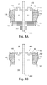
- FIGS. 4A-4F are partial cross-sectional side views of a feedthrough electrical connector extending through a hermetically sealed chamber housing showing various embodiments of deflection portions of springs coupled to the housing;
- FIG. 5A is a perspective view of a feedthrough electrical connector according to one embodiment
- FIG. 5B is a front view of the feedthrough electrical connector of FIG. 5A ;
- FIG. 5C is a top view of the feedthrough electrical connector of FIG. 5A ;
- FIG. 6A is a perspective view of a feedthrough electrical connector according to another embodiment
- FIG. 6B is a side view of the feedthrough electrical connector of FIG. 6A with corresponding electrical contacts according to one embodiment
- FIG. 7 is a magnified cross-sectional perspective view of a feedthrough electrical connector according to one embodiment.
- the hard disk drive 10 includes a housing 100 that defines an interior cavity 110 .
- the interior cavity 110 contains hard disks and other interior components 112 of the hard disk drive 10 .
- the feedthrough electrical connector 200 includes an electrically insulating base 210 with a plurality of electrical leads 220 disposed on at least one peripheral surface of the electrically insulating base 210 and a plurality of corresponding electrical traces (not shown) extending through the electrically insulating base.
- the electrical connector includes a plurality of pins (traces) extending through the electrically insulating base and a skirt positioned about a periphery of the electrically insulating base.
- the feedthrough electrical connector 200 electrically connects the interior components 112 of the hard disk drive with a computing device (not shown), while still maintaining the interior cavity 110 of the hard disk drive relatively isolated from the exterior atmosphere 120 . Additional details relating to the feedthrough electrical connector 200 are included below with reference to FIGS. 2-7 .
- the housing 100 of the hard disk drive 10 houses and protects the various internal components 112 configured to store and retrieve data and information, as well as to control the storage and retrieval of data and information.
- the components 112 within the interior cavity 110 may include magnetic recording media (e.g., disks), read/write heads, actuators (e.g., swings arms), electrical circuitry, and the like.
- the hard disk drive 10 can be in electrical communication with a computing device (not shown) to transfer data for operation of the computing device.
- the housing 100 is configured to hermetically seal the components 112 of the hard disk drive 10 from the exterior environment 120 .
- the housing 100 includes two or more sections coupled together to maintain the sealing nature of the housing.
- the housing 100 maintains the interior cavity 110 of the housing of the hard disk drive 10 at a pressure below atmospheric pressure. Because the components of hard disk drives, according to one embodiment, are sensitive to contaminants and pressure changes, hermetically sealing the internal components 112 of the hard disk drive 10 from the exterior environment 120 promotes the proper operation of the hard disk drive 10 and also extends the life of the hard disk drive 10 .
- the housing 100 may, in certain embodiments, include a connector receptacle 130 .
- the connector receptacle 130 is formed in an exterior surface of the housing 100 about a spring aperture 135 (see FIG. 2 ), which is also formed in the housing 100 .
- the spring aperture 135 in the absence of the spring 150 and the feedthrough electrical connector 200 , is open to the interior cavity 110 of the hard disk drive 10 .
- the connector receptacle 130 may be configured to receive and orient mating electrical connectors that are connectable with the electrical connector 200 . Although shown in FIG.
- the connector receptacle 130 may be sized similar to the electrical connector 200 in order to physically support the spring 150 or the protruding surfaces of the electrical connector 200 . Further, the connector receptacle 130 may be useful for retaining a layer of solder, adhesive, or other weldment agent for securing the spring 150 to the housing 100 . Further details regarding the spring 150 and the electrical connector 200 are included below.
- FIG. 2 is a schematic cross-sectional side view of a hard disk drive 10 with the feedthrough electrical connector 200 and the spring 250 , according to one embodiment.
- the hard disk drive 10 includes a housing 100 that substantially isolates the interior cavity 110 of the hard disk drive 10 from the exterior atmosphere 120 .
- the interior cavity 110 may have a helium enriched atmosphere or the interior cavity 110 may be maintained at a lower pressure than the pressure of the exterior atmosphere 120 .
- Certain hard disk drives 10 are specifically configured to have or maintain certain conditions within the interior cavity 110 to promote the efficient operation of the hard disk drive 10 . Leaks from the housing tend to disrupt the desired conditions within the interior cavity (e.g., cause an increase in pressure or introduction of heavier air), which can harm the efficiency and reliability of the hard disk drive 10 .
- the embodiment of the housing 100 depicted in FIG. 2 does not include a connector receptacle 130 (as depicted in FIG. 1 ).
- the housing 100 holds the components 112 of the hard disk drive, such as magnetic media and read/write arms.
- Also depicted schematically in the interior cavity 110 of the hard disk drive 10 are secondary electrical connections 114 that electrically connect the components 112 of the hard disk drive 10 to the feedthrough electrical connector 200 .
- the secondary electrical connections 114 may be wiring, electrical traces, connectors, controllers, control modules, and the like. Such secondary electrical connections 114 may be configured to connect with the feedthrough electrical connector 200 in a variety of ways, as recognized by those of ordinary skill in the art.
- the spring 250 which may be constructed of a metallic material, a plastic material, a polymeric material, or a composite material, among others, is coupled to the housing 100 and extends over and at least partially across the spring aperture 135 .
- the spring aperture 135 is an aperture formed in the wall of the housing 100 that is wider than the cross-sectional dimensions of the electrical connector 200 .
- the spring 250 may be directly coupled to the housing via any of various coupling techniques, such as techniques using solder, adhesive, or epoxy, among others. Additional details relating to the spring 250 are included below with reference to FIGS. 3A-4F .
- the spring 250 includes a feedthrough aperture 254 through which the electrical connector 200 extends and to which the electrical connector 250 is directly coupled.
- the coupling of the spring 250 to the housing 100 (across the spring aperture 135 ) and the coupling of the electrical connector 200 within the feedthrough aperture 254 creates a hermetic seal that isolates the interior cavity 110 from the exterior atmosphere 120 .
- the electrical connector 200 is indirectly coupled to the housing 100 via the spring 250 . In such an embodiment, direct engagement or contact between the electrical connector 200 and the housing, if any, is not contributing to the hermetic seal.
- the spring 250 includes a deflection portion 253 that helps to absorb thermal expansion of the electrical connector 200 relative to the housing 100 caused by thermal cycling (i.e., operation of the feedthrough connector).
- the deflection portion 253 is a bend, curve, twist, or bow in the spring. As will be described in greater detail below with reference to FIGS. 3A-4F , the deflection portion 253 compresses and expands as the electrical connector 200 thermally expands and compresses, respectively. In other words, the deflection portion 253 dampens and/or dissipates thermal or other expansion of the electrical connector 200 , thus helping to maintain the hermetic seal.
- the feedthrough electrical connector 200 includes an electrically insulating base 210 and a plurality of electrical leads 220 .
- the electrically insulating base 210 may include multiple layers of electrically insulating material with electrical traces extending between adjacent layers. For example, the multiple layers may extend in a direction perpendicular to the cross-sectional area of the feedthrough aperture 254 .
- the electrically insulating base 210 also includes three different portions or sections: an inwardly positioned portion 211 , a sealing portion 212 , and an outwardly positioned portion 213 .
- the electrically insulating base 210 may be a single, integrated structure. In other embodiments, the electrically insulating base 210 may be modular such that each portion 211 , 212 , 213 is a separate material. Further, in one embodiment, the electrically insulating base 210 may be layered ( FIG. 7 ). Additional details regarding the structure and composition of the electrically insulating base 210 are included below with reference to FIGS. 5A and 7 .
- the feedthrough electrical connector 200 has at least a first plurality of electrical leads 220 on the outwardly positioned portion 213 .
- the first plurality of electrical leads 220 may be disposed on at least one peripheral surface of the outwardly positioned portion 213 .
- the arrangement, material, and structure of the leads 220 are described in greater detail below with reference to FIG. 5A-7 .
- the first plurality of electrical leads 220 are electrically connected, via electrical traces/wires not depicted in FIG. 2 , to corresponding contact points on the inwardly positioned portion 211 of the electrically insulated base material 210 for connecting with the components 112 of the hard disk drive 10 .
- the inwardly positioned portion 211 of the electrically insulating base 210 of the feedthrough electrical connector 200 may or may not have similarly situated electrical leads.
- the secondary electrical connections 114 may electrically connect to the electrical connector 200 via leads disposed on the inwardly positioned portion 211 of the electrically insulating base 210 .
- the inwardly positioned portion of the electrically insulating base 210 may resemble a conventional electrical connector that has electrical contact points for interfacing with the integrated wiring 114 and components 112 of the hard disk drive 10 .
- the sealing portion 212 is the portion/region of the feedthrough electrical connector 200 that engages the feedthrough aperture 254 and couples the connector 200 to the spring 250 .
- the sealing portion 212 is electroplated with a soldering metal or other weldment facilitator for coupling the connector 200 to the spring 250 .
- the sealing portion 212 couples to the feedthrough aperture 254 via an adhesive composition. Additional details relating to the sealing portion 212 are included below with reference to FIG. 5A .
- the feedthrough electrical connector 200 has a first plurality of electrical leads 220 disposed on a distal end of the outwardly positioned portion 213 of the electrically insulating base 210 . These leads 220 are configured to be inserted into a corresponding/mated receptacle.
- the outwardly positioned portion 213 of the connector 200 may be a zero-insertion-force type of connector.
- the feedthrough electrical connector 200 may have a first plurality of electrical leads 220 disposed on a distal end of the outwardly positioned portion of the electrically insulating base 210 .
- FIGS. 3A-3C are top partial views of the feedthrough electrical connector 200 extending through the hermetically sealed chamber housing 100 showing various embodiments of spring footprints of springs coupled to the housing 100 .
- the spring extends across the spring aperture 135 in the housing 100 .
- the spring includes a deflection portion that facilitates absorbing thermal expansion of the electrical connector 200 caused by thermal cycling and thermal fluctuations.
- the deflection portion may have the form of an outwardly and/or inwardly oriented bend, bow, trench, or curve.
- FIG. 3A shows a spring 350 that includes a deflection portion 353 that has a rectangular spring footprint 352 .
- the term spring footprint is defined herein as the pattern of the deflection portion across the surface of the spring. In other words, the term spring footprint refers to the relative configuration and orientation of the deflection portion with respect to the feedthrough aperture (or electrical connector).
- the deflection portion 353 extends 360 degrees around the electrical connector 200 in a rectangular pattern.
- FIG. 3B shows a spring 360 with a deflection portion 363 that extends completely around the electrical connector 200 in an ovular (e.g., circular, elliptical, etc.) spring footprint 362 .
- FIG. 1 ovular
- the spring 370 includes a deflection portion 373 that does not extend completely around (i.e., does not completely circumscribe) the electrical connector 200 .
- the deflection portion 373 may extend in straight lines, for example, along two sides of the electrical connector 200 . In one embodiment, the deflection portion 373 extends along the two wider sides of the electrical connector 200 to absorb the out-of-plane thermal expansion of the electrical connector 200 .
- each of the springs 350 , 360 , 370 depicted in FIGS. 3A-3C is rectangular, it is expected that the outer peripheries of the springs may have other shapes, according to the specifics of a given application.
- the outer periphery of a spring may form a square shape or a circular shape.
- FIGS. 4A-4F are partial cross-sectional side views of the electrical connector 200 extending through the hermetically sealed chamber housing 100 showing various embodiments of deflection portions of springs coupled to the housing 100 .
- FIG. 4A shows one embodiment of a spring 450 that is coupled to an outer surface 103 of the housing 100 and has a deflection portion 453 with a rectangular rib profile. The deflection portion 453 protrudes outwardly away from the space 111 of the spring aperture and is able to facilitate absorbing the mechanical/structural stress imparted to the apparatus by the thermal expansion of the electrical connector 200 .
- the spring 450 may be coupled to the housing via soldering, weldment, epoxy, or adhesive, among others, in order to form a hermetic seal.
- a support bracket 160 coupled to the inner surface 101 of the housing.
- the support bracket 160 does not provide a sealing engagement with the electrical connector 200 and thus does not contribute to the hermetic seal of the housing.
- the internal atmosphere of the interior cavity 110 may extend beyond the support bracket 160 and into the space 111 of the spring aperture, as shown in FIGS. 4A-4F .
- the support bracket 160 may be coupled to the housing 100 via fasteners and/or adhesives, among others.
- the support bracket 160 may be optionally included to provide mechanical reinforcement to the feedthrough connection.
- the feedthrough connector and the spring are implemented without a support bracket.
- the support bracket 160 may be used to provide macro reinforcement.
- the support bracket 160 may be in non-sealing (e.g., supportive) engagement with the electrical connector 200 .
- the shape, size, orientation, and configuration of the support bracket 160 may be different than depicted in the figures of the present disclosure.
- the support bracket 160 may also have electrical traces/leads and may be utilized to make electrical connections with other components.
- FIG. 4B depicts a similar embodiment, only the spring 460 includes a deflection portion 463 that has a circular trench profile that indents inwardly.
- FIG. 4C shows a deflection portion 473 with a rectangular, wave-like trough profile.
- the deflection portion 473 of FIG. 4C may be considered a single deflection portion with two troughs facing in opposite directions.
- the deflection portion 473 may consist of two separate, spaced apart deflection portions.
- the spring may have multiple deflection portions spaced apart across the surface of the spring.
- FIG. 4D shows a deflection portion 483 with a circular, wave-like, trough profile.
- FIG. 4E depicts a spring 490 that is directly coupled to the sidewalls 102 of the spring aperture of the housing 100 .
- the spring 490 also includes a lip that extends to engage the inner surface 101 of the housing 100 .
- the spring 490 depicted in FIG. 4E does not have a deflection portion formed in a portion of the spring 490 but instead the entire spring 490 effectively forms a large deflection portion 493 .
- FIG. 4F depicts an embodiment similar to FIG. 4F , but the spring 495 in FIG. 4F also includes an indentation that forms a deflection portion 499 .
- a second support bracket 162 is also depicted in FIG. 4F .
- the second support bracket 162 may provide additional supporting engagement to the electrical connector 200 and/or may include electrical contacts/traces for facilitating electrical connections with other electrical components. It is expected that the spring may be implemented in other manners not explicitly described herein and/or may be implemented by combining various aspects of the several embodiments described herein.
- FIG. 5A is a perspective view of a feedthrough electrical connector 200 according to one embodiment.
- the feedthrough electrical connector 200 has an electrically insulating base 210 that defines the structure and overall shape of the connector 200 .
- the electrically insulating base 210 may be any non-conductive material that is suited for use in an electrical device.
- the electrically insulating base 210 may be glass, ceramic, rubber, plastic, polymer, and the like.
- the electrically insulating base 210 may be constructed in the same manner as printed circuit boards, printed wiring boards, etched wiring boards, printed circuit board assemblies, or circuit card assemblies.
- the electrically insulating base 210 includes electrical traces for conveying electric current and electrical signals between the first plurality of electrical leads 220 and the second plurality of electrical leads 230 .
- the electrically insulating base 210 implemented in the connector 200 may be selected according to the specific material's ability to withstand the conditions present in the interior cavity 110 of the hard disk drive 10 . For example, if a helium enriched atmosphere is maintained in the interior cavity 110 , an electrically insulating base 210 may be selected that has low helium permeability, thus promoting the isolation of the helium enriched interior cavity 110 from the exterior atmosphere 120 .
- the three portions 211 , 212 , 213 of the electrically insulating base 210 are also depicted in FIG. 5A .
- the three portions 211 , 212 , 213 may be a single, integrated structure.
- the electrically insulating base 210 may be modular such that each portion 211 , 212 , 213 is a separate material.
- the portions 211 , 212 , 213 may not be definitively marked and the portions may not be visually or structurally distinguishable from each other. In other words, the present disclosure distinguishes the portions 211 , 212 , 213 generally based on the expected arrangement and use of the feedthrough electrical connector 200 .
- the outwardly positioned portion 213 may be comparatively more rigid and may be constructed of a stronger non-conductive material so as to withstand the conditions of the exterior atmosphere and/or repeated connecting and disconnecting (depending on the specifics of a given application).
- the comparative lengths and relative dimensions of the three portions 211 , 212 , 213 are only illustrative of one embodiment and are not intended to restrict the scope of the disclosure. In other words, one portion may be substantially larger, longer, and/or wider than another portion, depending on the specifics of a given application.
- the number, size, configuration, and arrangement of the depicted electrical leads 220 , 230 are not restrictive of the scope of the present disclosure.
- the width of electrically insulating base 210 is substantially smaller than the length and the height of the electrically insulating base 210 .
- the sealing portion 212 may simply be a medial region where the connector 200 is coupled to the spring. However, in another embodiment the external surfaces of the sealing portion 212 may be electroplated with a soldering material. In another embodiment, the sealing portion 212 may include a prepared surface that is capable of bonding, through the use of an adhesive or epoxy, to the feedthrough aperture. In yet another embodiment, both and adhesive and solder (or other weldment agent) may be implemented to seal the connector 200 within the feedthrough aperture of the spring, thus substantially maintaining the interior cavity 110 isolated from the exterior atmosphere 120 . For example, in one embodiment, electroplating material may be disposed along the length of the sealing portion 212 and an adhesive may be disposed along the width of the sealing portion 212 .
- the sealing portion 212 may not only be the region of the connector 200 that is directly engaged with the feedthrough aperture. In one embodiment, the sealing portion 212 may extend beyond the thickness of the feedthrough aperture of the spring.
- the adhesive and/or the solder may be selected according to its ability to withstand the expected conditions within the interior cavity 110 or the exterior atmosphere 120 (e.g., low helium permeability).
- the electrically insulating base 210 may have a cross-sectional area, at least at the sealing portion, that is less than about 200 square millimeters. In a further embodiment, the cross-sectional area of the electrical connector may be less than about 100 square millimeters. In one embodiment, the electrical connector, at least in the sealing portion, has a cross-section that is co-planar with the cross-sectional area of the feedthrough aperture and that includes a first and second dimension. The first dimension, according to one embodiment, is substantially longer than the second direction. For example, the first dimension may be at least 5 times the length of the second dimension. In another implementation, the first dimension is at least 10 times the length of the second dimension.
- FIG. 5B is a front view of the feedthrough electrical connector 200 of FIG. 5A , according to one embodiment.
- the electrical connector 200 has a first plurality of leads 220 disposed on the outwardly positioned portion 213 and a second plurality of leads 230 disposed on the inwardly positioned portion 211 .
- the first 220 and second plurality of leads 230 are interconnected via traces/wiring extending the length of the electrically insulating base 210 (see FIG. 7 ).
- the first plurality of electrical leads 220 are disposed on at least one peripheral surface of the outwardly positioned portion 213 of the connector 200 .
- the second plurality of electrical leads 230 may be similar in arrangement and configuration to the first plurality of electrical leads 220 (as depicted in FIGS. 4 and 5A-5C ), in another embodiment may have the structure and configuration of a conventional electrical connector (i.e., electrical terminals, electrical contacts, wire couplings, etc.).
- a conventional electrical connector i.e., electrical terminals, electrical contacts, wire couplings, etc.
- the leads 220 , 230 may be constructed from any electrically conductive material that is suited for use in an electrical device.
- the electrical leads 220 , 230 may be constructed of metals such as copper, aluminum, gold, zinc, nickel, brass, bronze, iron, platinum, etc.
- the electrical leads 220 , 230 may be constructed of other conductive materials, such as graphite and conductive polymers.
- the number of leads in the first plurality of electrical leads 220 is not limited to the number depicted in the Figures.
- the feedthrough electrical connector 200 may less than 20 associated electrical leads. However, in another embodiment the feedthrough electrical connector 200 may have more than 20 associated electrical leads (i.e., hundreds or thousands) depending on the specifics of a given application.
- FIG. 5C is a top view of the feedthrough electrical connector 200 of FIG. 5A , according to one embodiment.
- the first plurality of electrical leads 220 may be disposed on opposing lateral peripheral sides 214 of the outwardly positioned portion 213 of the electrically insulating base 210 .
- the electrical leads 220 or at least a portion of the electrical leads 220 , may be exposed on the leading edge 215 of the connector 200 , thus allowing a mating connector to electrically engage the leads 220 on the peripheral sides 214 and/or the leading edge/surface 215 of the feedthrough connector 200 .
- the first plurality of electrical leads 220 may be disposed on all the lateral sides 214 of the feedthrough connector 200 instead of just two opposing sides. In another embodiment, the leads 220 may only be disposed on a single side. Further details and embodiments relating to the shape of the connector 200 and the arrangement of the leads 220 are included below.
- FIG. 6A is a perspective view of a feedthrough electrical connector 200 , according to another embodiment.
- the feedthrough electrical connector 200 may have a tapered design, thus potentially making the insertion of the outwardly positioned portion 213 into a mating receptacle (not shown) easier.
- sealing portion 212 may be tapered so as to reduce the effective footprint (cross-sectional area) of the connector 200 , thus reducing the size of the feedthrough aperture and reducing the likelihood of leakage between the interior cavity 110 and the exterior atmosphere 120 or rendering the sealing process more efficient/effective.
- the cross-sectional area of the electrical connector 200 at least at the sealing portion 212 , is less than about 200 square millimeters. In another embodiment, the cross-sectional areal of the electrical connector 200 is less than about 100 square millimeters.
- FIG. 6B is a side view of the feedthrough electrical connector 200 of FIG. 6A with corresponding mating receptacles 300 , according to one embodiment.
- the mating receptacles 300 have electrical contact pads 302 that, upon inserting the proper portion of the feedthrough electrical connector 200 into the receptacle, the leads 220 , 230 engage the electrical contact pads 302 and an electrical connection is made.
- the mating receptacles 300 may be electrically coupled to other components.
- the mating receptacles 300 and/or the feedthrough electrical connector 200 may have a securing mechanism that fastens the connector in place.
- the securing mechanism may be a latch, a clamp, a tie, a fastener, a bolt, clasp, pin, clip, etc.
- the connector may be held in place merely by the snug fit of the connector 200 within the mating receptacle(s) 300 .
- the connector may have shapes other than those depicted and described in the present disclosure.
- the electrical connector may have a generally racetrack-shaped, ellipse-shaped, or ovular-shaped outer periphery.
- the outer perimeter of the electrical connector 200 or at least the outer perimeter of one of the portions 211 , 212 , 213 of the connector 200 , may have various shapes.
- the outer perimeter of the connector 200 may include two opposing sides extending substantially parallel to each other, with the sides being coupled together by semi-circular ends.
- the outer perimeter (i.e., footprint) of the connector 200 may have a circular shape.
- the connector 200 may be void of relatively sharp corners or edges.
- FIG. 7 is a magnified perspective view of a feedthrough electrical connector 200 , according to one embodiment.
- the electrical connector 200 includes leads 220 disposed on peripheral surfaces of the electrically insulating base 210 .
- multiple leads 220 may be spaced apart in multiple directions across the peripheral surfaces of the electrically insulating base 210 .
- the leads 220 may be spaced apart down the length of the connector 200 .
- the electrically insulating base 210 may include multiple layers 210 a , 210 b , 210 c , 210 d , 210 e , 210 f formed together.
- electrical traces 240 can be electrically connected to the leads 220 and extend the length of the connector 200 to connect with corresponding leads/contact points 230 on the opposite end (e.g., between the inwardly positioned portion 211 to the outwardly positioned portion 213 ).
- the electrical traces 240 may be constructed from any electrically conductive material that is suited for use in an electrical device.
- the electrical traces 240 may be constructed of metals such as copper, aluminum, gold, zinc, nickel, brass, bronze, iron, platinum, etc.
- the electrical traces 240 may be constructed of other conductive materials, such as graphite and conductive polymers.
- the number and configuration of the traces 240 and the layers 210 a , 210 b , 210 c , 210 d , 210 e , 210 f is not limited to the depicted embodiment. Depending on the specifics of a given application, many layers 210 a , 210 b , 210 c , 210 d , 210 e , 210 f may be incorporated to properly route the traces 240 .
- instances in this specification where one element is “coupled” to another element can include direct and indirect coupling.
- Direct coupling can be defined as one element coupled to and in some contact with another element.
- Indirect coupling can be defined as coupling between two elements not in direct contact with each other, but having one or more additional elements between the coupled elements.
- securing one element to another element can include direct securing and indirect securing.
- adjacent does not necessarily denote contact. For example, one element can be adjacent another element without being in contact with that element.
- the phrase “at least one of”, when used with a list of items, means different combinations of one or more of the listed items may be used and only one of the items in the list may be needed.
- the item may be a particular object, thing, or category.
- “at least one of” means any combination of items or number of items may be used from the list, but not all of the items in the list may be required.
- “at least one of item A, item B, and item C” may mean item A; item A and item B; item B; item A, item B, and item C; or item B and item C.
- “at least one of item A, item B, and item C” may mean, for example, without limitation, two of item A, one of item B, and ten of item C; four of item B and seven of item C; or some other suitable combination.
- first,” “second,” etc. are used herein merely as labels, and are not intended to impose ordinal, positional, or hierarchical requirements on the items to which these terms refer. Moreover, reference to, e.g., a “second” item does not require or preclude the existence of, e.g., a “first” or lower-numbered item, and/or, e.g., a “third” or higher-numbered item.
Abstract
Description
Claims (5)
Priority Applications (2)
| Application Number | Priority Date | Filing Date | Title |
|---|---|---|---|
| US14/518,853 US9431759B2 (en) | 2014-10-20 | 2014-10-20 | Feedthrough connector for hermetically sealed electronic devices |
| US15/223,976 US9691434B2 (en) | 2014-10-20 | 2016-07-29 | Feedthrough connector for hermetically sealed electronic devices |
Applications Claiming Priority (1)
| Application Number | Priority Date | Filing Date | Title |
|---|---|---|---|
| US14/518,853 US9431759B2 (en) | 2014-10-20 | 2014-10-20 | Feedthrough connector for hermetically sealed electronic devices |
Related Child Applications (1)
| Application Number | Title | Priority Date | Filing Date |
|---|---|---|---|
| US15/223,976 Continuation US9691434B2 (en) | 2014-10-20 | 2016-07-29 | Feedthrough connector for hermetically sealed electronic devices |
Publications (2)
| Publication Number | Publication Date |
|---|---|
| US20160111814A1 US20160111814A1 (en) | 2016-04-21 |
| US9431759B2 true US9431759B2 (en) | 2016-08-30 |
Family
ID=55749792
Family Applications (2)
| Application Number | Title | Priority Date | Filing Date |
|---|---|---|---|
| US14/518,853 Active US9431759B2 (en) | 2014-10-20 | 2014-10-20 | Feedthrough connector for hermetically sealed electronic devices |
| US15/223,976 Active US9691434B2 (en) | 2014-10-20 | 2016-07-29 | Feedthrough connector for hermetically sealed electronic devices |
Family Applications After (1)
| Application Number | Title | Priority Date | Filing Date |
|---|---|---|---|
| US15/223,976 Active US9691434B2 (en) | 2014-10-20 | 2016-07-29 | Feedthrough connector for hermetically sealed electronic devices |
Country Status (1)
| Country | Link |
|---|---|
| US (2) | US9431759B2 (en) |
Cited By (8)
| Publication number | Priority date | Publication date | Assignee | Title |
|---|---|---|---|---|
| US9704539B2 (en) * | 2015-12-09 | 2017-07-11 | Western Digital Technologies, Inc. | Hermetic sealing of hard disk drive using laminated film seal |
| US9721620B2 (en) | 2015-12-09 | 2017-08-01 | Western Digital Technologies, Inc. | Hermetic sealing of hard disk drive using laminated film seal |
| US9721619B2 (en) | 2015-12-09 | 2017-08-01 | Western Digital Technologies, Inc. | Hermetic sealing of hard disk drive using laminated film seal |
| US10162393B2 (en) * | 2016-01-13 | 2018-12-25 | Seagate Technology Llc | Electrical connector with force balancing |
| US10395694B1 (en) * | 2017-08-09 | 2019-08-27 | Western Digital Technologies, Inc. | Low permeability electrical feed-through |
| US10622756B1 (en) * | 2018-09-24 | 2020-04-14 | Apple Inc. | Gaskets for sealing spring-loaded contacts |
| US11087795B2 (en) * | 2019-03-15 | 2021-08-10 | Kabushiki Kaisha Toshiba | Magnetic disk device |
| US11735843B2 (en) * | 2020-10-07 | 2023-08-22 | Pegatron Corporation | Connector and manufacturing method thereof |
Families Citing this family (20)
| Publication number | Priority date | Publication date | Assignee | Title |
|---|---|---|---|---|
| EP2754265A4 (en) * | 2011-09-07 | 2015-04-29 | Tsx Inc | High availability system, replicator and method |
| US10042730B2 (en) * | 2014-08-19 | 2018-08-07 | Western Digital Technologies, Inc. | Mass storage chassis assembly configured to accommodate predetermined number of storage drive failures |
| US9734874B1 (en) * | 2016-02-02 | 2017-08-15 | Western Digital Technologies, Inc. | Adhesive leak channel structure for hermetic sealing of a hard disk drive |
| US11063382B2 (en) | 2018-05-22 | 2021-07-13 | Flowserve Management Company | Waterproof and explosion-proof circuit board and electronic valve actuator for flow control applications |
| US10917996B1 (en) | 2019-07-19 | 2021-02-09 | Dell Products L.P. | System and method for device level thermal management and electromagnetic interference management |
| US11644425B2 (en) | 2019-07-19 | 2023-05-09 | Dell Products L.P. | System and method for optical state determination |
| US11399450B2 (en) | 2019-07-19 | 2022-07-26 | Dell Products L.P. | System and method for managing electromagnetic interference |
| US10980159B2 (en) | 2019-07-19 | 2021-04-13 | Dell Products L.P. | System and method for managing multiple connections |
| US11129307B2 (en) | 2019-07-19 | 2021-09-21 | Dell Products L.P. | System and method for managing thermal states of devices |
| US11122718B2 (en) | 2019-07-19 | 2021-09-14 | Dell Products L.P. | System and method for device level electromagnetic interference management |
| US11234347B2 (en) * | 2019-07-19 | 2022-01-25 | Dell Products L.P. | System and method for physical management of devices |
| US11143682B2 (en) | 2019-07-19 | 2021-10-12 | Dell Products L.P. | System and method for communicating externally from an electromagnetic interference suppressed volume |
| US11378608B2 (en) | 2019-07-19 | 2022-07-05 | Dell Products L.P. | System and method for device state determination |
| US11132038B2 (en) | 2019-07-19 | 2021-09-28 | Dell Products L.P. | System and method for thermal management of shadowed devices |
| US11147194B2 (en) | 2019-08-21 | 2021-10-12 | Dell Products L.P. | System and method for managing electromagnetic interference |
| US11234350B2 (en) | 2019-08-21 | 2022-01-25 | Dell Products L.P. | System and method for isolated device access |
| DE102019219135A1 (en) * | 2019-12-09 | 2020-10-08 | Zf Friedrichshafen Ag | Plug device for receiving a plug and method for producing a plug device |
| US11308994B2 (en) * | 2020-04-20 | 2022-04-19 | Seagate Technology Llc | Top cover spring designs |
| WO2023121309A1 (en) * | 2021-12-21 | 2023-06-29 | 주식회사 솔루엠 | Charger |
| WO2024024553A1 (en) * | 2022-07-28 | 2024-02-01 | 京セラ株式会社 | Connector, connector module, and storage device |
Citations (48)
| Publication number | Priority date | Publication date | Assignee | Title |
|---|---|---|---|---|
| EP0529345A2 (en) | 1991-08-05 | 1993-03-03 | Molex Incorporated | Card edge connector assembly |
| US5282099A (en) | 1990-08-31 | 1994-01-25 | Kabushiki Kaisha Toshiba | Disk drive apparatus incorporating circuitry into housing |
| US5337202A (en) | 1990-11-09 | 1994-08-09 | Seagate Technology, Inc. | Actuator arm assembly printed circuit cable to external printed circuit board interface apparatus |
| US5454157A (en) | 1992-10-14 | 1995-10-03 | Maxtor Corporation | Method of manufacturing a hermetically sealed disk drive |
| US5541787A (en) * | 1990-11-09 | 1996-07-30 | Seagate Technology, Inc. | Head disc assembly with printed circuit cable connector adapted for automated assembly |
| US5816861A (en) * | 1994-05-17 | 1998-10-06 | Hon Hai Precision Ind. Co., Ltd. | System for use with detachable hard disk drive |
| US5931697A (en) * | 1996-06-18 | 1999-08-03 | Samsung Electronics Co., Ltd. | Device for connecting a hard disk assembly to a printed circuit board |
| US5956213A (en) | 1988-01-25 | 1999-09-21 | Seagate Technology, Inc. | Latch mechanism for disk drive using magnetic field of actuator magnets |
| US5994975A (en) | 1998-04-28 | 1999-11-30 | Trw Inc. | Millimeter wave ceramic-metal feedthroughs |
| US6129579A (en) * | 1998-06-15 | 2000-10-10 | Segate Technology Inc. | Low inductance flex-to-PCB spring connector for a disc drive |
| US6168459B1 (en) * | 1998-06-15 | 2001-01-02 | Seagate Technology Llc | Flex support and seal apparatus for a disc drive |
| US6305975B1 (en) * | 2000-10-12 | 2001-10-23 | Bear Instruments, Inc. | Electrical connector feedthrough to low pressure chamber |
| US6454572B1 (en) * | 2000-02-25 | 2002-09-24 | Seagate Technology Llc | Surface mount connector |
| US20020141107A1 (en) * | 2001-03-29 | 2002-10-03 | Kumaraswamy Kasetty | Drive housing with integrated electrical connectors |
| US20030022533A1 (en) * | 2001-06-16 | 2003-01-30 | Sung-Hyuk Joo | Signal transmission connector in a computer hard disk drive |
| US6594107B2 (en) | 2001-07-23 | 2003-07-15 | Hitachi, Ltd. | Magnetic disc apparatus having wiring on the outer bottom |
| US6678112B1 (en) | 1999-05-18 | 2004-01-13 | Fujitsu Limited | Disk drive device |
| US6970322B2 (en) | 2003-06-18 | 2005-11-29 | Seagate Technology Llc | Bulkhead connector for low leak rate disc drives |
| US20060002067A1 (en) | 2004-02-19 | 2006-01-05 | Gunderson Neal F | Electrical interface for sealed enclosures |
| US6989493B2 (en) | 2004-03-03 | 2006-01-24 | Seagate Technology Llc | Electrical feedthrough assembly for a sealed housing |
| US20060050429A1 (en) * | 2004-02-19 | 2006-03-09 | Gunderson Neal F | Flex spring for sealed connections |
| US7016145B2 (en) | 2003-02-19 | 2006-03-21 | Seagate Technology Llc | Hermetically sealed data storage device |
| US7123440B2 (en) | 2003-09-29 | 2006-10-17 | Hitachi Global Storage Technologies Netherlands B.V. | Hermetically sealed electronics arrangement and approach |
| US20080171465A1 (en) * | 2007-01-17 | 2008-07-17 | Fci Americas Technology, Inc. | Disc drive head stack assembly |
| US20080182431A1 (en) * | 2007-01-29 | 2008-07-31 | Fci Americas Technology, Inc. | Disk drive interposer |
| US20080259503A1 (en) | 2007-04-19 | 2008-10-23 | Akihiko Aoyagi | Magnetic disk drive and soldering method of feed-through |
| US20090034113A1 (en) | 2004-10-21 | 2009-02-05 | Hideyuki Hashi | Disk device and electronic equipment using the same |
| US20090097375A1 (en) | 2007-10-10 | 2009-04-16 | Kouki Uefune | Disk drive device and manufacturing method thereof |
| US20090097163A1 (en) | 2007-10-12 | 2009-04-16 | Hiroyuki Suzuki | Data storage device |
| US20090168233A1 (en) | 2007-12-26 | 2009-07-02 | Takashi Kouno | Manufacturing method of hermetic connection terminal used in a disk drive device having hermetically sealed enclosure and disk drive device |
| US7599147B2 (en) * | 2005-08-05 | 2009-10-06 | Seagate Technology Llc | Electrical feedthrough assembly with elastic ring interface |
| US20100068936A1 (en) * | 2008-09-15 | 2010-03-18 | Pacific Aerospace & Electronics, Inc. | Connector assemblies incorporating ceramic inserts having conductive pathways and interfaces |
| US20100328815A1 (en) * | 2008-02-01 | 2010-12-30 | Hitachi, Ltd. | Magnetic disk device |
| US7872836B2 (en) * | 2007-01-09 | 2011-01-18 | Hitachi Global Storage Technologies Netherlands B.V. | Disk drive device |
| US7876527B2 (en) * | 2006-06-07 | 2011-01-25 | Hitachi Global Storage Technologies, Netherlands, B.V. | Magnetic disk device |
| US8059364B1 (en) | 2004-05-04 | 2011-11-15 | Maxtor Corporation | Hermetically sealed connector interface |
| US8194348B2 (en) | 2010-02-26 | 2012-06-05 | Western Digital Technologies, Inc. | Sealed laminated electrical connector for helium filled disk drive |
| US20120182645A1 (en) | 2011-01-17 | 2012-07-19 | Alphana Technology Co., Ltd. | Rotating machine comprising insulation sheet for insulating coil and base, and method of producing the rotating machine |
| US8279552B2 (en) | 2010-06-22 | 2012-10-02 | Hitachi Global Storage Technologies, Netherlands B.V. | Hermetically sealing a hard disk drive |
| US8373075B2 (en) | 2009-10-29 | 2013-02-12 | Medtronic, Inc. | Implantable co-fired electrical feedthroughs |
| US8487187B2 (en) | 2009-09-09 | 2013-07-16 | Emerson Electric Co. | Solid core glass bead seal with stiffening rib |
| US8749914B2 (en) | 2011-09-08 | 2014-06-10 | HGST Netherlands B.V. | Disk-enclosure base configured to inhibit formation of adherent solder-flux residue |
| US9001458B1 (en) | 2013-12-06 | 2015-04-07 | HGST Netherlands B.V. | Hard disk drive sealed in helium using a secondary container |
| US20150098178A1 (en) | 2013-10-04 | 2015-04-09 | HGST Netherlands B.V. | Hard disk drive with feedthrough connector |
| US20150257293A1 (en) | 2014-03-06 | 2015-09-10 | HGST Netherlands B.V. | Feedthrough connector for hermetically sealed electronic devices |
| US20150359115A1 (en) | 2014-06-05 | 2015-12-10 | HGST Netherlands B.V. | Storage canister with multiple storage device mounting elements |
| US20150355685A1 (en) | 2014-06-05 | 2015-12-10 | HGST Netherlands B.V. | Sealed storage canister |
| US20160111124A1 (en) | 2014-10-15 | 2016-04-21 | HGST Netherlands B.V. | Fluid Dynamic Bearing Groove Configuration |
Family Cites Families (7)
| Publication number | Priority date | Publication date | Assignee | Title |
|---|---|---|---|---|
| US3279552A (en) | 1965-01-25 | 1966-10-18 | Howe Richardson Scale Co | Automatic tare control system for weighing apparatus |
| CA2071662A1 (en) | 1991-06-26 | 1992-12-27 | Jon J. Gulick | Integrated socket-type package for flip-chip semiconductor devices and circuits |
| US5154644A (en) | 1992-01-15 | 1992-10-13 | Molex Incorporated | Edge connector for a printed circuit card |
| KR20070093450A (en) | 2005-02-08 | 2007-09-18 | 나노넥서스, 인코포레이티드 | High density interconnect system for ic packages and interconnect assemblies |
| JP2007088104A (en) | 2005-09-20 | 2007-04-05 | Fuji Xerox Co Ltd | Card edge substrate |
| US7476124B2 (en) | 2006-12-19 | 2009-01-13 | Seagate Technology Llc | Feedthrough connector with plated electrical trace |
| US8476538B2 (en) | 2010-03-08 | 2013-07-02 | Formfactor, Inc. | Wiring substrate with customization layers |
-
2014
- 2014-10-20 US US14/518,853 patent/US9431759B2/en active Active
-
2016
- 2016-07-29 US US15/223,976 patent/US9691434B2/en active Active
Patent Citations (53)
| Publication number | Priority date | Publication date | Assignee | Title |
|---|---|---|---|---|
| US5956213A (en) | 1988-01-25 | 1999-09-21 | Seagate Technology, Inc. | Latch mechanism for disk drive using magnetic field of actuator magnets |
| US5282099A (en) | 1990-08-31 | 1994-01-25 | Kabushiki Kaisha Toshiba | Disk drive apparatus incorporating circuitry into housing |
| US5337202A (en) | 1990-11-09 | 1994-08-09 | Seagate Technology, Inc. | Actuator arm assembly printed circuit cable to external printed circuit board interface apparatus |
| US5541787A (en) * | 1990-11-09 | 1996-07-30 | Seagate Technology, Inc. | Head disc assembly with printed circuit cable connector adapted for automated assembly |
| EP0529345A2 (en) | 1991-08-05 | 1993-03-03 | Molex Incorporated | Card edge connector assembly |
| US5454157A (en) | 1992-10-14 | 1995-10-03 | Maxtor Corporation | Method of manufacturing a hermetically sealed disk drive |
| US5816861A (en) * | 1994-05-17 | 1998-10-06 | Hon Hai Precision Ind. Co., Ltd. | System for use with detachable hard disk drive |
| US5931697A (en) * | 1996-06-18 | 1999-08-03 | Samsung Electronics Co., Ltd. | Device for connecting a hard disk assembly to a printed circuit board |
| US5994975A (en) | 1998-04-28 | 1999-11-30 | Trw Inc. | Millimeter wave ceramic-metal feedthroughs |
| US6129579A (en) * | 1998-06-15 | 2000-10-10 | Segate Technology Inc. | Low inductance flex-to-PCB spring connector for a disc drive |
| US6168459B1 (en) * | 1998-06-15 | 2001-01-02 | Seagate Technology Llc | Flex support and seal apparatus for a disc drive |
| US6678112B1 (en) | 1999-05-18 | 2004-01-13 | Fujitsu Limited | Disk drive device |
| US6454572B1 (en) * | 2000-02-25 | 2002-09-24 | Seagate Technology Llc | Surface mount connector |
| US6305975B1 (en) * | 2000-10-12 | 2001-10-23 | Bear Instruments, Inc. | Electrical connector feedthrough to low pressure chamber |
| US20020141107A1 (en) * | 2001-03-29 | 2002-10-03 | Kumaraswamy Kasetty | Drive housing with integrated electrical connectors |
| US6567235B2 (en) | 2001-03-29 | 2003-05-20 | Maxtor Corporation | Drive housing with integrated electrical connectors |
| US20030022533A1 (en) * | 2001-06-16 | 2003-01-30 | Sung-Hyuk Joo | Signal transmission connector in a computer hard disk drive |
| US6594107B2 (en) | 2001-07-23 | 2003-07-15 | Hitachi, Ltd. | Magnetic disc apparatus having wiring on the outer bottom |
| US7016145B2 (en) | 2003-02-19 | 2006-03-21 | Seagate Technology Llc | Hermetically sealed data storage device |
| US6970322B2 (en) | 2003-06-18 | 2005-11-29 | Seagate Technology Llc | Bulkhead connector for low leak rate disc drives |
| US7123440B2 (en) | 2003-09-29 | 2006-10-17 | Hitachi Global Storage Technologies Netherlands B.V. | Hermetically sealed electronics arrangement and approach |
| US20060002067A1 (en) | 2004-02-19 | 2006-01-05 | Gunderson Neal F | Electrical interface for sealed enclosures |
| US20060050429A1 (en) * | 2004-02-19 | 2006-03-09 | Gunderson Neal F | Flex spring for sealed connections |
| US6989493B2 (en) | 2004-03-03 | 2006-01-24 | Seagate Technology Llc | Electrical feedthrough assembly for a sealed housing |
| US8059364B1 (en) | 2004-05-04 | 2011-11-15 | Maxtor Corporation | Hermetically sealed connector interface |
| US20090034113A1 (en) | 2004-10-21 | 2009-02-05 | Hideyuki Hashi | Disk device and electronic equipment using the same |
| US7599147B2 (en) * | 2005-08-05 | 2009-10-06 | Seagate Technology Llc | Electrical feedthrough assembly with elastic ring interface |
| US7876527B2 (en) * | 2006-06-07 | 2011-01-25 | Hitachi Global Storage Technologies, Netherlands, B.V. | Magnetic disk device |
| US7872836B2 (en) * | 2007-01-09 | 2011-01-18 | Hitachi Global Storage Technologies Netherlands B.V. | Disk drive device |
| US20080171465A1 (en) * | 2007-01-17 | 2008-07-17 | Fci Americas Technology, Inc. | Disc drive head stack assembly |
| US20080182431A1 (en) * | 2007-01-29 | 2008-07-31 | Fci Americas Technology, Inc. | Disk drive interposer |
| US8179631B2 (en) | 2007-04-19 | 2012-05-15 | Hitachi Global Storage Technologies Netherlands B.V. | Magnetic disk drive feed-through solder connection with solder fillet formed inside base and protruding outside base |
| US20080259503A1 (en) | 2007-04-19 | 2008-10-23 | Akihiko Aoyagi | Magnetic disk drive and soldering method of feed-through |
| US20090097375A1 (en) | 2007-10-10 | 2009-04-16 | Kouki Uefune | Disk drive device and manufacturing method thereof |
| US20090097163A1 (en) | 2007-10-12 | 2009-04-16 | Hiroyuki Suzuki | Data storage device |
| US8035923B2 (en) | 2007-10-12 | 2011-10-11 | Hitachi Global Storage Technologies Netherlands B.V. | Data storage device |
| US8098454B2 (en) | 2007-12-26 | 2012-01-17 | Hitachi Global Storage Technologies Netherlands B.V. | Manufacturing method of hermetic connection terminal used in a disk drive device having hermetically sealed enclosure and disk drive device |
| US20090168233A1 (en) | 2007-12-26 | 2009-07-02 | Takashi Kouno | Manufacturing method of hermetic connection terminal used in a disk drive device having hermetically sealed enclosure and disk drive device |
| US20100328815A1 (en) * | 2008-02-01 | 2010-12-30 | Hitachi, Ltd. | Magnetic disk device |
| US20100068936A1 (en) * | 2008-09-15 | 2010-03-18 | Pacific Aerospace & Electronics, Inc. | Connector assemblies incorporating ceramic inserts having conductive pathways and interfaces |
| US8487187B2 (en) | 2009-09-09 | 2013-07-16 | Emerson Electric Co. | Solid core glass bead seal with stiffening rib |
| US8373075B2 (en) | 2009-10-29 | 2013-02-12 | Medtronic, Inc. | Implantable co-fired electrical feedthroughs |
| US8194348B2 (en) | 2010-02-26 | 2012-06-05 | Western Digital Technologies, Inc. | Sealed laminated electrical connector for helium filled disk drive |
| US8279552B2 (en) | 2010-06-22 | 2012-10-02 | Hitachi Global Storage Technologies, Netherlands B.V. | Hermetically sealing a hard disk drive |
| US20120182645A1 (en) | 2011-01-17 | 2012-07-19 | Alphana Technology Co., Ltd. | Rotating machine comprising insulation sheet for insulating coil and base, and method of producing the rotating machine |
| US8749914B2 (en) | 2011-09-08 | 2014-06-10 | HGST Netherlands B.V. | Disk-enclosure base configured to inhibit formation of adherent solder-flux residue |
| US20150098178A1 (en) | 2013-10-04 | 2015-04-09 | HGST Netherlands B.V. | Hard disk drive with feedthrough connector |
| US9001458B1 (en) | 2013-12-06 | 2015-04-07 | HGST Netherlands B.V. | Hard disk drive sealed in helium using a secondary container |
| US20150257293A1 (en) | 2014-03-06 | 2015-09-10 | HGST Netherlands B.V. | Feedthrough connector for hermetically sealed electronic devices |
| US9196303B2 (en) * | 2014-03-06 | 2015-11-24 | HGST Netherlands, B.V. | Feedthrough connector for hermetically sealed electronic devices |
| US20150359115A1 (en) | 2014-06-05 | 2015-12-10 | HGST Netherlands B.V. | Storage canister with multiple storage device mounting elements |
| US20150355685A1 (en) | 2014-06-05 | 2015-12-10 | HGST Netherlands B.V. | Sealed storage canister |
| US20160111124A1 (en) | 2014-10-15 | 2016-04-21 | HGST Netherlands B.V. | Fluid Dynamic Bearing Groove Configuration |
Non-Patent Citations (4)
| Title |
|---|
| European Search Report and search opinion for European Application No. 15157645.1 dated Jul. 7, 2015. |
| Notice of Allowance for U.S. Appl. No. 14/199,133 dated Jul. 10, 2015. |
| Office Action for U.S. Appl. No. 14/199,133 dated Mar. 24, 2015. |
| SGA Technologies, Multi Pin Feedthrough, http://www.sgatech.cauk/glass-to-metal-seals/types-of-seal/multi-pin-feedthrough, Received Jan. 29, 2014, Retrieved Mar. 6, 2014. |
Cited By (10)
| Publication number | Priority date | Publication date | Assignee | Title |
|---|---|---|---|---|
| US9704539B2 (en) * | 2015-12-09 | 2017-07-11 | Western Digital Technologies, Inc. | Hermetic sealing of hard disk drive using laminated film seal |
| US9721620B2 (en) | 2015-12-09 | 2017-08-01 | Western Digital Technologies, Inc. | Hermetic sealing of hard disk drive using laminated film seal |
| US9721619B2 (en) | 2015-12-09 | 2017-08-01 | Western Digital Technologies, Inc. | Hermetic sealing of hard disk drive using laminated film seal |
| US10162393B2 (en) * | 2016-01-13 | 2018-12-25 | Seagate Technology Llc | Electrical connector with force balancing |
| US10395694B1 (en) * | 2017-08-09 | 2019-08-27 | Western Digital Technologies, Inc. | Low permeability electrical feed-through |
| US10515668B2 (en) | 2017-08-09 | 2019-12-24 | Western Digital Technologies, Inc. | Low permeability electrical feed-through |
| US10622756B1 (en) * | 2018-09-24 | 2020-04-14 | Apple Inc. | Gaskets for sealing spring-loaded contacts |
| US10931058B2 (en) | 2018-09-24 | 2021-02-23 | Apple Inc. | Gaskets for sealing spring-loaded contacts |
| US11087795B2 (en) * | 2019-03-15 | 2021-08-10 | Kabushiki Kaisha Toshiba | Magnetic disk device |
| US11735843B2 (en) * | 2020-10-07 | 2023-08-22 | Pegatron Corporation | Connector and manufacturing method thereof |
Also Published As
| Publication number | Publication date |
|---|---|
| US9691434B2 (en) | 2017-06-27 |
| US20160336044A1 (en) | 2016-11-17 |
| US20160111814A1 (en) | 2016-04-21 |
Similar Documents
| Publication | Publication Date | Title |
|---|---|---|
| US9691434B2 (en) | Feedthrough connector for hermetically sealed electronic devices | |
| US9196303B2 (en) | Feedthrough connector for hermetically sealed electronic devices | |
| US9819129B2 (en) | Hard disk drive with feedthrough connector | |
| TWI283452B (en) | Wafer support attachment for a semi-conductor wafer transport container | |
| CN101676994B (en) | Information storage device having disk drive and bridge controller PCB within monolithic conductive nest | |
| JP5098772B2 (en) | Electrical component unit | |
| JPS59501564A (en) | electric circuit unit | |
| CN107632674A (en) | Information-storing device with the damping insertion piece between housing cabin and disc driver | |
| JP2008537333A (en) | Layered structure of integrated circuits on other integrated circuits | |
| US10236617B2 (en) | Socket equipped with linked cap pair | |
| US8465008B2 (en) | Complex wave spring | |
| US4934944A (en) | Chip carrier socket with open aperture | |
| US11139602B2 (en) | Electrical connector and assembly method thereof | |
| KR101385444B1 (en) | Collet for picking up and conveying semi conductor | |
| US20130050961A1 (en) | Device and method for providing water resistance for a flexible printed circuit or flexible wire device | |
| US20060024575A1 (en) | Sealed battery pack | |
| US7887356B1 (en) | Socket connector having protursions for positioning IC package | |
| US20090323294A1 (en) | Memory card and method of manufacturing the same | |
| JP6495791B2 (en) | Semiconductor device | |
| TWI811623B (en) | check socket | |
| CN215707932U (en) | Chip tray | |
| US11749950B2 (en) | Shielding housing structure of electric connector with features for heat ventilation and electromagnetic shielding | |
| WO2024024553A1 (en) | Connector, connector module, and storage device | |
| CN216960668U (en) | Shielding case and circuit board with same | |
| US9320151B2 (en) | Protective sleeve for electrical components |
Legal Events
| Date | Code | Title | Description |
|---|---|---|---|
| AS | Assignment |
Owner name: HGST NETHERLANDS B.V., NETHERLANDS Free format text: ASSIGNMENT OF ASSIGNORS INTEREST;ASSIGNORS:HIRANO, TOSHIKI;VITIKKATE, VIPIN A.;SIGNING DATES FROM 20141015 TO 20141017;REEL/FRAME:033986/0512 |
|
| STCF | Information on status: patent grant |
Free format text: PATENTED CASE |
|
| AS | Assignment |
Owner name: WESTERN DIGITAL TECHNOLOGIES, INC., CALIFORNIA Free format text: ASSIGNMENT OF ASSIGNORS INTEREST;ASSIGNOR:HGST NETHERLANDS B.V.;REEL/FRAME:040829/0516 Effective date: 20160831 |
|
| AS | Assignment |
Owner name: JPMORGAN CHASE BANK, N.A., AS AGENT, ILLINOIS Free format text: SECURITY INTEREST;ASSIGNOR:WESTERN DIGITAL TECHNOLOGIES, INC.;REEL/FRAME:052915/0566 Effective date: 20200113 |
|
| MAFP | Maintenance fee payment |
Free format text: PAYMENT OF MAINTENANCE FEE, 4TH YEAR, LARGE ENTITY (ORIGINAL EVENT CODE: M1551); ENTITY STATUS OF PATENT OWNER: LARGE ENTITY Year of fee payment: 4 |
|
| AS | Assignment |
Owner name: WESTERN DIGITAL TECHNOLOGIES, INC., CALIFORNIA Free format text: RELEASE OF SECURITY INTEREST AT REEL 052915 FRAME 0566;ASSIGNOR:JPMORGAN CHASE BANK, N.A.;REEL/FRAME:059127/0001 Effective date: 20220203 |
|
| AS | Assignment |
Owner name: JPMORGAN CHASE BANK, N.A., ILLINOIS Free format text: PATENT COLLATERAL AGREEMENT - A&R LOAN AGREEMENT;ASSIGNOR:WESTERN DIGITAL TECHNOLOGIES, INC.;REEL/FRAME:064715/0001 Effective date: 20230818 Owner name: JPMORGAN CHASE BANK, N.A., ILLINOIS Free format text: PATENT COLLATERAL AGREEMENT - DDTL LOAN AGREEMENT;ASSIGNOR:WESTERN DIGITAL TECHNOLOGIES, INC.;REEL/FRAME:067045/0156 Effective date: 20230818 |