US9427047B2 - Methods of manufacturing articles of footwear with tensile strand elements - Google Patents
Methods of manufacturing articles of footwear with tensile strand elements Download PDFInfo
- Publication number
- US9427047B2 US9427047B2 US14/552,645 US201414552645A US9427047B2 US 9427047 B2 US9427047 B2 US 9427047B2 US 201414552645 A US201414552645 A US 201414552645A US 9427047 B2 US9427047 B2 US 9427047B2
- Authority
- US
- United States
- Prior art keywords
- strand
- material layer
- area
- thread
- lace
- Prior art date
- Legal status (The legal status is an assumption and is not a legal conclusion. Google has not performed a legal analysis and makes no representation as to the accuracy of the status listed.)
- Active, expires
Links
- 238000000034 method Methods 0.000 title claims description 63
- 238000004519 manufacturing process Methods 0.000 title claims description 47
- 239000000463 material Substances 0.000 claims abstract description 291
- 238000005520 cutting process Methods 0.000 claims description 27
- XLYOFNOQVPJJNP-UHFFFAOYSA-N water Substances O XLYOFNOQVPJJNP-UHFFFAOYSA-N 0.000 claims description 9
- 238000005304 joining Methods 0.000 claims 4
- 239000002243 precursor Substances 0.000 description 59
- 210000002683 foot Anatomy 0.000 description 57
- 230000008569 process Effects 0.000 description 32
- 239000002861 polymer material Substances 0.000 description 21
- 239000004753 textile Substances 0.000 description 20
- 210000000474 heel Anatomy 0.000 description 19
- 229920000642 polymer Polymers 0.000 description 19
- 229920001169 thermoplastic Polymers 0.000 description 19
- 230000033001 locomotion Effects 0.000 description 15
- 239000011800 void material Substances 0.000 description 11
- 230000008901 benefit Effects 0.000 description 9
- 239000006260 foam Substances 0.000 description 8
- 210000000452 mid-foot Anatomy 0.000 description 8
- 239000000835 fiber Substances 0.000 description 6
- 238000003698 laser cutting Methods 0.000 description 6
- 210000004744 fore-foot Anatomy 0.000 description 5
- 210000003423 ankle Anatomy 0.000 description 4
- 239000012530 fluid Substances 0.000 description 4
- 239000006250 one-dimensional material Substances 0.000 description 4
- 239000004677 Nylon Substances 0.000 description 3
- 239000000853 adhesive Substances 0.000 description 3
- 230000001070 adhesive effect Effects 0.000 description 3
- 230000000386 athletic effect Effects 0.000 description 3
- 230000000694 effects Effects 0.000 description 3
- 229920001778 nylon Polymers 0.000 description 3
- 239000013589 supplement Substances 0.000 description 3
- 210000003371 toe Anatomy 0.000 description 3
- 239000004760 aramid Substances 0.000 description 2
- 229920003235 aromatic polyamide Polymers 0.000 description 2
- 229920001971 elastomer Polymers 0.000 description 2
- 230000001747 exhibiting effect Effects 0.000 description 2
- 239000006261 foam material Substances 0.000 description 2
- 230000008570 general process Effects 0.000 description 2
- 239000010985 leather Substances 0.000 description 2
- 239000002649 leather substitute Substances 0.000 description 2
- 230000009192 sprinting Effects 0.000 description 2
- OKTJSMMVPCPJKN-UHFFFAOYSA-N Carbon Chemical compound [C] OKTJSMMVPCPJKN-UHFFFAOYSA-N 0.000 description 1
- RYGMFSIKBFXOCR-UHFFFAOYSA-N Copper Chemical compound [Cu] RYGMFSIKBFXOCR-UHFFFAOYSA-N 0.000 description 1
- 229920000742 Cotton Polymers 0.000 description 1
- LFQSCWFLJHTTHZ-UHFFFAOYSA-N Ethanol Chemical compound CCO LFQSCWFLJHTTHZ-UHFFFAOYSA-N 0.000 description 1
- 229920000106 Liquid crystal polymer Polymers 0.000 description 1
- 239000004977 Liquid-crystal polymers (LCPs) Substances 0.000 description 1
- 229920000297 Rayon Polymers 0.000 description 1
- 229910000831 Steel Inorganic materials 0.000 description 1
- 239000004699 Ultra-high molecular weight polyethylene Substances 0.000 description 1
- XAGFODPZIPBFFR-UHFFFAOYSA-N aluminium Chemical compound [Al] XAGFODPZIPBFFR-UHFFFAOYSA-N 0.000 description 1
- 229910052782 aluminium Inorganic materials 0.000 description 1
- 229920006231 aramid fiber Polymers 0.000 description 1
- 230000004888 barrier function Effects 0.000 description 1
- 210000000459 calcaneus Anatomy 0.000 description 1
- 229910052799 carbon Inorganic materials 0.000 description 1
- 238000000576 coating method Methods 0.000 description 1
- 239000002131 composite material Substances 0.000 description 1
- 239000010949 copper Substances 0.000 description 1
- 229910052802 copper Inorganic materials 0.000 description 1
- 230000001351 cycling effect Effects 0.000 description 1
- BFMKFCLXZSUVPI-UHFFFAOYSA-N ethyl but-3-enoate Chemical compound CCOC(=O)CC=C BFMKFCLXZSUVPI-UHFFFAOYSA-N 0.000 description 1
- 239000004744 fabric Substances 0.000 description 1
- 239000011521 glass Substances 0.000 description 1
- 230000009477 glass transition Effects 0.000 description 1
- 238000010438 heat treatment Methods 0.000 description 1
- 230000009191 jumping Effects 0.000 description 1
- 239000010410 layer Substances 0.000 description 1
- 238000002844 melting Methods 0.000 description 1
- 230000008018 melting Effects 0.000 description 1
- 210000001872 metatarsal bone Anatomy 0.000 description 1
- 238000012986 modification Methods 0.000 description 1
- 230000004048 modification Effects 0.000 description 1
- 239000004745 nonwoven fabric Substances 0.000 description 1
- 230000035699 permeability Effects 0.000 description 1
- 229920000728 polyester Polymers 0.000 description 1
- 229920002635 polyurethane Polymers 0.000 description 1
- 239000004814 polyurethane Substances 0.000 description 1
- 239000002964 rayon Substances 0.000 description 1
- 230000003014 reinforcing effect Effects 0.000 description 1
- 239000007787 solid Substances 0.000 description 1
- 238000009987 spinning Methods 0.000 description 1
- 230000000087 stabilizing effect Effects 0.000 description 1
- 239000010959 steel Substances 0.000 description 1
- 239000000126 substance Substances 0.000 description 1
- 229920001187 thermosetting polymer Polymers 0.000 description 1
- 229920000785 ultra high molecular weight polyethylene Polymers 0.000 description 1
Images


Classifications
-
- A—HUMAN NECESSITIES
- A43—FOOTWEAR
- A43D—MACHINES, TOOLS, EQUIPMENT OR METHODS FOR MANUFACTURING OR REPAIRING FOOTWEAR
- A43D86/00—Machines for assembling soles or heels onto uppers, not provided for in groups A43D25/00 - A43D83/00, e.g. by welding
-
- A—HUMAN NECESSITIES
- A43—FOOTWEAR
- A43B—CHARACTERISTIC FEATURES OF FOOTWEAR; PARTS OF FOOTWEAR
- A43B23/00—Uppers; Boot legs; Stiffeners; Other single parts of footwear
- A43B23/02—Uppers; Boot legs
-
- A—HUMAN NECESSITIES
- A43—FOOTWEAR
- A43B—CHARACTERISTIC FEATURES OF FOOTWEAR; PARTS OF FOOTWEAR
- A43B23/00—Uppers; Boot legs; Stiffeners; Other single parts of footwear
- A43B23/02—Uppers; Boot legs
- A43B23/0205—Uppers; Boot legs characterised by the material
- A43B23/0235—Different layers of different material
-
- A—HUMAN NECESSITIES
- A43—FOOTWEAR
- A43B—CHARACTERISTIC FEATURES OF FOOTWEAR; PARTS OF FOOTWEAR
- A43B23/00—Uppers; Boot legs; Stiffeners; Other single parts of footwear
- A43B23/02—Uppers; Boot legs
- A43B23/0245—Uppers; Boot legs characterised by the constructive form
-
- A—HUMAN NECESSITIES
- A43—FOOTWEAR
- A43B—CHARACTERISTIC FEATURES OF FOOTWEAR; PARTS OF FOOTWEAR
- A43B23/00—Uppers; Boot legs; Stiffeners; Other single parts of footwear
- A43B23/02—Uppers; Boot legs
- A43B23/0245—Uppers; Boot legs characterised by the constructive form
- A43B23/025—Uppers; Boot legs characterised by the constructive form assembled by stitching
-
- A—HUMAN NECESSITIES
- A43—FOOTWEAR
- A43B—CHARACTERISTIC FEATURES OF FOOTWEAR; PARTS OF FOOTWEAR
- A43B23/00—Uppers; Boot legs; Stiffeners; Other single parts of footwear
- A43B23/02—Uppers; Boot legs
- A43B23/0245—Uppers; Boot legs characterised by the constructive form
- A43B23/0265—Uppers; Boot legs characterised by the constructive form having different properties in different directions
- A43B23/0275—Uppers; Boot legs characterised by the constructive form having different properties in different directions with a part of the upper particularly rigid, e.g. resisting articulation or torsion
-
- A—HUMAN NECESSITIES
- A43—FOOTWEAR
- A43C—FASTENINGS OR ATTACHMENTS OF FOOTWEAR; LACES IN GENERAL
- A43C1/00—Shoe lacing fastenings
- A43C1/04—Shoe lacing fastenings with rings or loops
-
- D—TEXTILES; PAPER
- D05—SEWING; EMBROIDERING; TUFTING
- D05B—SEWING
- D05B53/00—Thread- or cord-laying mechanisms; Thread fingers
-
- A—HUMAN NECESSITIES
- A43—FOOTWEAR
- A43C—FASTENINGS OR ATTACHMENTS OF FOOTWEAR; LACES IN GENERAL
- A43C1/00—Shoe lacing fastenings
Definitions
- An article of footwear may have an upper and a sole structure secured together.
- the upper includes at least two material layers and a plurality of strand segments.
- the material layers are located adjacent to each other and in an overlapping configuration, and the material layers are located in (a) a lace region that includes a plurality of lace-receiving elements and (b) a lower region proximal to an area where the sole structure is secured to the upper.
- the strand segments extend from the lace region to the lower region.
- the strand segments are located and secured between the material layers in the lace region and the lower region.
- the strand segments form both an exterior surface of the upper and an opposite interior surface of the upper in an area between the lace region and the lower region.
- the material layers define an opening between the lace region and the lower region, and the strand segments extend across the opening.
- Various example methods for manufacturing a tensile strand element of the upper are also disclosed.
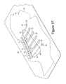
- FIGS. 6A and 6B are exploded perspective views of the portions of the tensile strand element, as defined in FIG. 4
- the following discussion and accompanying figures disclose various articles of footwear having uppers that include tensile strand elements.
- the articles of footwear are disclosed, for purposes of example, as having configurations of running shoes, sprinting shoes, and basketball shoes.
- Concepts associated with the articles of footwear, including the uppers may also be applied to a variety of other athletic footwear types, including baseball shoes, cross-training shoes, cycling shoes, football shoes, tennis shoes, golf shoes, soccer shoes, walking shoes, hiking boots, ski and snowboard boots, and ice and roller skates, for example.
- the concepts may also be applied to footwear types that are generally considered to be non-athletic, including dress shoes, loafers, sandals, and work boots.
- the concepts disclosed herein apply, therefore, to a wide variety of footwear types.
- a durable and wear-resistant material layer may be secured to exterior material layer 41 to form the exterior surface of upper 30 .
- Trademarks, aesthetic elements, or other indicia may also be secured to exterior material layer 41 .
- a polymer foam layer may be secured to interior material layer 42 to enhance the comfort of footwear 10
- a textile layer may be secured to the polymer foam layer to form a portion of the interior surface of upper 30 , enhance comfort, and wick moisture (e.g., from perspiration) away from the foot.
- Strand 45 also resists stretch in upper 30 due to flexing of footwear 10 in the area between forefoot region 11 and midfoot region 12 to ensure that the heel area of the foot remains properly positioned in upper 30 and relative to sole structure 20 . Accordingly, strands 43 and 45 cooperatively (a) resist stretch in upper 30 due to cutting motions to ensure that the foot remains properly positioned relative to footwear 10 and (b) resist stretch in upper 30 due to braking motions, as well as jumping and running motions that flex or otherwise bend footwear 10 .
- FIG. 10D depicts a configuration of tensile strand element 40 that may be utilized in the configuration of footwear 10 depicted in FIG. 9E .
- tensile strand element 40 includes strands 43 and 45 .
- both of strands 43 and 45 may be located and secured between material layers 41 and 42 .
- FIGS. 11 and 12 an enlarged and more detailed area of tensile strand element 40 is depicted.
- strand 45 is located between interior material layer 42 and a backing material layer 46 .
- the general process discussed relative to FIGS. 14C and 14D is performed multiple times, as depicted in FIG. 14E , to repeatedly (a) extend strand 43 across opening 44 , (b) stitch strand 43 to interior material layer 42 in locations that generally corresponds with each of regions 36 and 37 , and (c) form loops from strand 43 in lace region 36 . Additionally, the cording machine repeatedly extends thread 63 across opening 44 .
- the cording machine then extends strand 43 across opening 44 once again and around one of lower pegs 72 , as depicted in FIG. 16F .
- the general process discussed relative to FIGS. 16E and 16F is now performed multiple times, as depicted in FIG. 16G , to (a) repeatedly extend segments of strand 43 across opening 44 and between regions 36 and 37 , (b) alternately extend strand 43 around one of lace pegs 71 and lower pegs 72 , and (c) form loops from strand 43 in lace region 36 and around lace apertures 34 .
- a portion of strand 43 may be stitched to interior material layer 42 .
- strand 43 is depicted as being stitched to interior material layer 42 around one of lower pegs 72 .
- a substantially completed tensile strand element 40 may be removed from excess portions of precursor elements 61 and 65 , as depicted in FIG. 16K , with die cutting, laser cutting, or manual cutting, for example.
- the assembled elements forming tensile strand element 40 are then incorporated into footwear 10 such that (a) lace apertures 34 and the loops formed by strand 43 are located in lace region 36 and (b) areas across opening 44 are located in lower region 37 . Lace 33 is also threaded through the various lace apertures 34 .
Abstract
An upper for an article of footwear may have material layers and a plurality of strand segments. The material layers are located adjacent to each other and in an overlapping configuration, and the material layers are located in a lace region and a lower region of the upper. The strand segments extend from the lace region to the lower region. The strand segments may be located and secured between the material layers in the lace region and the lower region. The strand segments may form both an exterior surface of the upper and an opposite interior surface of the upper in an area between the lace region and the lower region. The material layers may define an opening between the lace region and the lower region, and the strand segments extend across the opening.
Description
This application is a division of U.S. patent application Ser. No. 13/404,483, filed on Feb. 24, 2012 and entitled “Methods Of Manufacturing Articles Of Footwear With Tensile Strand Elements”, the disclosure of which application is entirely incorporated herein by reference.
Articles of footwear generally include two primary elements: an upper and a sole structure. The upper is often formed from a plurality of material elements (e.g., textiles, polymer sheet layers, polymer foam layers, leather, synthetic leather) that are stitched or adhesively bonded together to form a void within the footwear for comfortably and securely receiving a foot. More particularly, the upper forms a structure that extends over instep and toe areas of the foot, along medial and lateral sides of the foot, and around a heel area of the foot. The upper may also incorporate a lacing system to adjust fit of the footwear, as well as permitting entry and removal of the foot from the void within the upper. In addition, the upper may include a tongue that extends under the lacing system to enhance adjustability and comfort of the footwear, and the upper may incorporate a heel counter for stabilizing the heel area of the foot.
The sole structure is secured to a lower portion of the upper and positioned between the foot and the ground. In athletic footwear, for example, the sole structure often includes a midsole and an outsole. The midsole may be formed from a polymer foam material that attenuates ground reaction forces (i.e., provides cushioning) during walking, running, and other ambulatory activities. The midsole may also include fluid-filled chambers, plates, moderators, or other elements that further attenuate forces, enhance stability, or influence the motions of the foot, for example. In some configurations, the midsole may be primarily formed from a fluid-filled chamber. The outsole forms a ground-contacting element of the footwear and is usually fashioned from a durable and wear-resistant rubber material that includes texturing to impart traction. The sole structure may also include a sockliner positioned within the void of the upper and proximal a lower surface of the foot to enhance footwear comfort.
An article of footwear may have an upper and a sole structure secured together. The upper includes at least two material layers and a plurality of strand segments. The material layers are located adjacent to each other and in an overlapping configuration, and the material layers are located in (a) a lace region that includes a plurality of lace-receiving elements and (b) a lower region proximal to an area where the sole structure is secured to the upper. The strand segments extend from the lace region to the lower region. In some configurations, the strand segments are located and secured between the material layers in the lace region and the lower region. In some configurations, the strand segments form both an exterior surface of the upper and an opposite interior surface of the upper in an area between the lace region and the lower region. In some configurations, the material layers define an opening between the lace region and the lower region, and the strand segments extend across the opening. Various example methods for manufacturing a tensile strand element of the upper are also disclosed.
In another configuration, an upper for an article of footwear includes a plurality of material elements and strand segments. The material elements are joined together to define a lace region and a lower region. The material elements include a base material layer located in at least the lace region The base material layer has a first surface and an opposite second surface, and the base material layer defines an aperture of a lace-receiving element that extends from the first surface to the second surface in the lace region. The lower region is spaced from the lace region and located proximal to an area where the sole structure is secured to the upper. The strand segments extend from the lace region to the lower region and include a first strand segment and a second strand segment. The first strand segment is located adjacent to the first surface of the base material layer and extends at least partially around the aperture. The second strand segment is located adjacent to the second surface of the base material layer and extends at least partially around the aperture.
A method of manufacturing an article of footwear includes locating a strand adjacent to a surface of a base material layer, with the strand extending from a first area of the base material layer to a second area of the base material layer. The strand is secured to the base material layer. The strand and the base material layer are incorporated into a footwear upper, with the first area being located in a lace region of the upper and the second area being located in a lower region of the upper. The lower region is spaced from the lace region and located proximal to an area for securing a sole structure to the upper.
The advantages and features of novelty characterizing aspects of the invention are pointed out with particularity in the appended claims. To gain an improved understanding of the advantages and features of novelty, however, reference may be made to the following descriptive matter and accompanying figures that describe and illustrate various configurations and concepts related to the invention.
The foregoing Summary and the following Detailed Description will be better understood when read in conjunction with the accompanying figures.
The following discussion and accompanying figures disclose various articles of footwear having uppers that include tensile strand elements. The articles of footwear are disclosed, for purposes of example, as having configurations of running shoes, sprinting shoes, and basketball shoes. Concepts associated with the articles of footwear, including the uppers, may also be applied to a variety of other athletic footwear types, including baseball shoes, cross-training shoes, cycling shoes, football shoes, tennis shoes, golf shoes, soccer shoes, walking shoes, hiking boots, ski and snowboard boots, and ice and roller skates, for example. The concepts may also be applied to footwear types that are generally considered to be non-athletic, including dress shoes, loafers, sandals, and work boots. The concepts disclosed herein apply, therefore, to a wide variety of footwear types.
General Footwear Structure
An article of footwear 10 is depicted in FIGS. 1 and 2 as including a sole structure 20 and an upper 30. Sole structure 20 is secured to a lower area of upper 30 and extends between upper 30 and the ground. Upper 30 provides a comfortable and secure covering for a foot of a wearer. As such, the foot may be located within upper 30, which effectively secures the foot within footwear 10, and sole structure 20 extends under the foot to attenuate forces, enhance stability, or influence the motions of the foot, for example. Additional details of footwear 10 are depicted in the cross-sectional views of FIGS. 3A-3C .
For purposes of reference in the following discussion, footwear 10 may be divided into three general regions: a forefoot region 11, a midfoot region 12, and a heel region 13. Forefoot region 11 generally includes portions of footwear 10 corresponding with the toes and the joints connecting the metatarsals with the phalanges. Midfoot region 12 generally includes portions of footwear 10 corresponding with an arch area of the foot. Heel region 13 generally corresponds with rear portions of the foot, including the calcaneus bone. Footwear 10 also includes a lateral side 14 and a medial side 15, which extend through each of regions 11-13 and correspond with opposite sides of footwear 10. More particularly, lateral side 14 corresponds with an outside area of the foot (i.e. the surface that faces away from the other foot), and medial side 15 corresponds with an inside area of the foot (i.e., the surface that faces toward the other foot). Regions 11-13 and sides 14-15 are not intended to demarcate precise areas of footwear 10. Rather, regions 11-13 and sides 14-15 are intended to represent general areas of footwear 10 to aid in the following discussion. In addition to footwear 10, regions 11-13 and sides 14-15 may also be applied to sole structure 20, upper 30, and individual elements thereof.
For purposes of reference in the following discussion, upper 30 also includes a lace region 36 and a lower region 37, as shown for example in FIG. 2 . Lace region 36 is proximal to and includes an area where lace apertures 34 or other lace-receiving elements are located. In general, lace region 36 may correspond with a throat area of footwear 10, which includes one or more of lace 33, lace apertures 34, and tongue 35. Lower region 37 is proximal to and includes an area where sole structure 20 is secured to upper 30. Regions 36 and 37 are not intended to demarcate precise areas of footwear 30. Rather, regions 36 and 37 are intended to represent general areas to aid in the following discussion.
Tensile Strand Element
Although a variety of material elements or other components may be incorporated into upper 30, areas of one or both of lateral side 14 and medial side 15 incorporate a tensile strand element 40 that includes an exterior material layer 41, an interior material layer 42, and a strand 43. An example of one tensile strand element 40 is depicted in FIG. 4 and has a configuration suitable for extending through each of regions 11-13 on lateral side 14. A similar or identical tensile strand element may also extend through medial side 15. In further configurations, a single tensile strand element 40 may extend through each of sides 14 and 15, or tensile strand element 40 may only extend through a relatively small area of lateral side 14. Accordingly, the shape and size of tensile strand 40, as well as the area of upper 30 in which tensile strand element 40 is located, may vary considerably. Additional details of tensile strand element 40 are depicted in FIGS. 5A-7C .
Material layers 41 and 42 are located adjacent to each other and are generally coextensive with or otherwise overlap each other. Although material layers 41 and 42 are often stitched, bonded, adhered, or otherwise secured to each other, material layers 41 and 42 may also be unsecured. With reference to FIGS. 3A and 3B , for example, exterior material layer 41 is located outward from interior material layer 42. In this position, exterior material layer 41 forms a portion of an exterior surface of upper 30, and interior material layer 42 forms a portion of an interior surface of upper 30, thereby defining a portion of void 31. In other configurations, additional material layers or elements may be secured to one or both of material layers 41 and 42. For example, a durable and wear-resistant material layer may be secured to exterior material layer 41 to form the exterior surface of upper 30. Trademarks, aesthetic elements, or other indicia may also be secured to exterior material layer 41. As another example, which is discussed in greater detail below, a polymer foam layer may be secured to interior material layer 42 to enhance the comfort of footwear 10, and a textile layer may be secured to the polymer foam layer to form a portion of the interior surface of upper 30, enhance comfort, and wick moisture (e.g., from perspiration) away from the foot.
During activities that involve walking, running, or other ambulatory movements (e.g., cutting, braking), a foot within void 31 may tend to stretch upper 30. That is, many of the material elements forming upper 30 (e.g., material layers 41 and 42) may stretch when placed in tension by movements of the foot. Although strand 43 or individual segments of strand 43 may also stretch, strand 43 generally stretches to a lesser degree than the other material elements forming upper 30. The various segments of strand 43 may be located, therefore, to form structural components in upper 30 that (a) resist stretching in specific directions or locations, (b) limit excess movement of the foot relative to sole structure 20 and upper 30, (c) ensure that the foot remains properly positioned relative to sole structure 20 and upper 30, and (d) reinforce locations where forces are concentrated.
In addition to extending between regions 36 and 37, the segments of strand 43 also extend at least partially around each of lace apertures 34. As such, a segment of strand 43 extends (a) upward from lower region 37 to lace region 36, (b) around one of lace apertures 33, and (c) downward from lace region 36 to lower region 37 in a repeating pattern. In this manner, strand 43 effectively extends around each of lace apertures 34. Moreover, segments of strand 43 form loops around portions of lace 33, as generally depicted in FIGS. 1 and 2 , as well as the cross-sections of FIGS. 3A-3C . Moreover, the configuration of material layers 41 and 42 and strand 43 in the area of one of lace apertures 34 is depicted in FIGS. 5A and 6A . When lace 33 is tightened, tension in lace 33 effectively places strand 43 in tension, which has the advantage of tightening upper 30 around the foot and further (a) limiting excess movement of the foot relative to sole structure 20 and upper 30 and (b) ensuring that the foot remains properly positioned relative to sole structure 20 and upper 30.
Each of material layers 41 and 42 may be formed from any generally two-dimensional material. As utilized with respect to the present invention, the term “two-dimensional material” or variants thereof is intended to encompass generally flat materials exhibiting a length and a width that are substantially greater than a thickness. Accordingly, suitable materials for material layers 41 and 42 include various textiles, polymer sheets, or combinations of textiles and polymer sheets, for example. Material layers 41 and 42 may also be leather, synthetic leather, or polymer foam layers. Textiles are generally manufactured from fibers, filaments, or yarns that are, for example, either (a) produced directly from webs of fibers by bonding, fusing, or interlocking to construct non-woven fabrics and felts or (b) formed through a mechanical manipulation of yarn to produce a woven or knitted fabric. The textiles may incorporate fibers that are arranged to impart one-directional stretch or multi-directional stretch, and the textiles may include coatings that form a breathable and water-resistant barrier, for example. The polymer sheets may be extruded, rolled, or otherwise formed from a polymer material to exhibit a generally flat aspect. Two-dimensional materials may also encompass laminated or otherwise layered materials that include two or more layers of textiles, polymer sheets, or combinations of textiles and polymer sheets. In addition to textiles and polymer sheets, other two-dimensional materials may be utilized for material layers 41 and 42. Although two-dimensional materials may have smooth or generally untextured surfaces, some two-dimensional materials will exhibit textures or other surface characteristics, such as dimpling, protrusions, ribs, or various patterns, for example. Despite the presence of surface characteristics, two-dimensional materials remain generally flat and exhibit a length and a width that are substantially greater than a thickness. In some configurations, mesh materials or perforated materials may be utilized for either or both of material layers 43 and 44 to impart greater breathability or air permeability.
As examples, interior material layer 42 may be formed from a textile material and exterior material layer 41 may be formed from a polymer sheet that is bonded to the textile material, or each of material layers 41 and 42 may be formed from polymer sheets that are bonded to each other. In circumstances where interior material layer 42 is formed from a textile material, exterior material layer 41 may incorporate thermoplastic polymer materials that bond with the textile material of interior material layer 42. That is, by heating exterior material layer 42, the thermoplastic polymer material of exterior material layer 42 may bond with the textile material of interior material layer 41, as well as strand 43. As an alternative, a thermoplastic polymer material may infiltrate or be bonded with the textile material of interior material layer 42 in order to bond with exterior material layer 41 and strand 43. That is, interior material layer 42 may be a combination of a textile material and a thermoplastic polymer material. An advantage of this configuration is that the thermoplastic polymer material may rigidify or otherwise stabilize the textile material of interior material layer 42 during the manufacturing process of tensile strand element 40, including portions of the manufacturing process involving laying and securing strand 43 upon interior material layer 42. Another advantage of this configuration is that another material layer may be bonded to interior material layer 42 opposite exterior material layer 41 using the thermoplastic polymer material in some configurations. This general concept is disclosed in U.S. patent application Ser. No. 12/180,235, which was filed in the U.S. Patent and Trademark Office on 25 Jul. 2008 and entitled Composite Element With A Polymer Connecting Layer, such prior application being entirely incorporated herein by reference.
As an example, strand 43 may be formed from a bonded nylon 6.6 with a breaking or tensile strength of 3.1 kilograms and a weight of 45 tex, or strands 43 may be formed from a bonded nylon 6.6 with a breaking or tensile strength of 6.2 kilograms and a tex of 45. As a further example, strand 43 may have an outer sheath 51 that extends around an inner core 52, as depicted in FIG. 8 . Sheath 51 and core 52 extend along a length of strand 43, thereby extending from lace region 36 to lower region 37. Also, each of sheath 51 and core 52 may be formed from a plurality of intertwined (e.g., braided, woven) threads. In another configuration, sheath 51 may be formed from intertwined threads, and core 52 may be bundled threads with or without twist. Advantages of forming strand 43 to include sheath 51 and core 52 are that (a) sheath 51 imparts protection to core 52 and (b) each may have advantageous properties that are combined.
Based upon the above discussion, footwear 10 is generally formed from upper 20 and sole structure 30, which are secured together. Upper 20 may be formed from a plurality of material elements, such as material layers 41 and 42, and includes both lace region 36 and lower region 37. Whereas lace region 36 includes a plurality of lace-receiving elements, such as lace apertures 34, lower region 37 is proximal to an area where sole structure 20 is secured to upper 30. A plurality of segments of strand 43 extend from lace region 36 to lower region 37. The segments of strand 43 are secured to upper 30 in lace region 36 and lower region 37, and the segments of strand 43 are unsecured for a distance of at least four centimeters in an area between lace region 36 and lower region 37. In some configurations, segments of strand 43 form both the exterior surface of upper 30 and the opposite interior surface of upper 30 in the area between lace region 36 and lower region 37. Additionally, in some configurations, the material layers forming upper 30 define opening 44 between lace region 36 and lower region 37, with the segments of strand 43 extending across opening 44.
Further Configurations
The various features discussed above provide example configurations for footwear 10 and tensile strand element 40. In further configurations, however, numerous features of footwear 10 and tensile strand element 40 may vary to impart a variety of properties or aesthetics to footwear 10. Although various examples of further configurations are discussed below, a variety of other configurations may also fall within the scope of the present discussion. Moreover, although the configurations are discussed and depicted separately, aspects of some configurations may be utilized in combination with aspects of other configurations.
A further configuration of footwear 10 is depicted in FIG. 9A , wherein opening 44 extends from ankle opening 32 in heel region 13 to an area between lace region 36 and lower region 37 in midfoot region 12. Forward areas of opening 44 may also extend into forefoot region 11. Whereas opening 44 is discussed above as being located in an inner area of tensile strand element 40 and is spaced inward from edges of material layers 41 and 42, this configuration of opening 44 extends to the edges of material layers 41 and 42. Advantages of this configuration include (a) removing additional mass from footwear 10, (b) facilitating greater breathability in footwear 10, and (c) imparting a different aesthetic to footwear 10. A similar configuration is depicted in FIG. 9B , wherein another strand 43 extends from a upper area to a lower area of heel region 13 and effectively supports the portion of upper 20 that contacts the heel of the wearer.
Another configuration of footwear 10 is depicted in FIG. 9C as including a bootie element 38. As discussed above, the various segments of strand 43 form both the exterior surface and the interior surface of upper 20 in the area between lace region 36 and lower region 37, specifically in opening 44. As such, strand 43 may contact the foot or a sock worn over the foot. Bootie element 38, however, is locatable within void 31 and provides a covering for the foot and effectively extends between strand 43 and the foot. The various segments of strand 43 may, therefore, lay against bootie element 38. Although bootie element 38 may be a knitted element with the configuration of a sock, bootie element 38 may incorporate various elements that (a) impart structure or stability to footwear 10, (b) enhance comfort, (c) assist sole structure 20 in attenuating ground reaction forces, or (d) improve water resistance, for example.
Referring to FIG. 9D , footwear 10 is depicted as having a configuration of a sprinting shoe, which is generally used during sprint-related track and field events. Although sprint shoes may exhibit various configurations, sole structure 20 includes a plurality of spikes 24 that impart traction. With respect to upper 30, opening 44 extends from ankle opening 32 in heel region 13 to an area between lace region 36 and lower region 37 in midfoot region 12. While segments of strand 43 located in forward areas of midfoot region 12 extend in a generally vertical direction, other segments of strand 43 angle rearwardly. As such, the various segments of strand 43 may extend in various directions. Moreover, segments of strand 43 extend in a generally horizontal direction in heel region 13 and join with an upper area of upper 30 in heel region 13. When lace 33 is tensioned and tied, portions of upper 30 in heel region 13 may be tightened to further enhance the fit of footwear 10 and ensure that footwear 10 remains properly positioned on the foot during the sprint-related track and field events.
Another configuration of footwear 10 is depicted in FIG. 9E as having a configuration of a basketball shoe. In each of the configurations discussed above, only strand 43 extended around each of lace apertures 34. In this configuration, however, segments of strand 43 and segments of a strand 45 extend around each of lace apertures 34 and across opening 44. Whereas segments of strand 43 are oriented in a generally vertical direction between regions 36 and 37, segments of strand 45 are oriented in a rearwardly-angled direction between regions 36 and 37. This general configuration is disclosed in U.S. patent application Ser. No. 12/847,836, which was filed in the U.S. Patent and Trademark Office on 30 Jul. 2010 and entitled Footwear Incorporating Angled Tensile Strand Elements, such prior application being entirely incorporated herein by reference. Given this orientation, many segments of strand 43 are located in midfoot region 12, but some segments of strand 45 are partially located in midfoot region 12 and extend into heel region 13.
In the configuration of FIG. 9E , segments of strand 43 have a generally vertical orientation between regions 36 and 37. When performing a cutting motion (i.e., side-to-side movement of the wearer), strand 43 resists sideways movement of the foot to ensure that the foot remains properly positioned relative to footwear 10. That is, strand 43 resists stretch in upper 30 that may otherwise allow the foot to roll off of sole structure 20. Segments of strand 45 are oriented in a rearwardly-angled direction in the area between regions 36 and 37. When performing a braking motion (i.e., slowing the forward momentum of the wearer), strand 45 resists stretch in upper 30 that may allow the foot to slide forward or separate from sole structure 20. Strand 45 also resists stretch in upper 30 due to flexing of footwear 10 in the area between forefoot region 11 and midfoot region 12 to ensure that the heel area of the foot remains properly positioned in upper 30 and relative to sole structure 20. Accordingly, strands 43 and 45 cooperatively (a) resist stretch in upper 30 due to cutting motions to ensure that the foot remains properly positioned relative to footwear 10 and (b) resist stretch in upper 30 due to braking motions, as well as jumping and running motions that flex or otherwise bend footwear 10.
Continuing with the discussion of FIG. 9E , segments of strand 43 are oriented in a generally vertical direction, whereas segments of strand 45 are oriented in a rearwardly-angled direction. Although segments of strand 43 may have a vertical orientation, the angle of the segments of strand 43 may also have a substantially vertical orientation between zero and twenty degrees from vertical. As utilized herein, the term “substantially vertical orientation” and similar variants thereof is defined as an orientation wherein segments of strand 43. Although the orientation of the segments of strand 45 may vary, the angle of the segments of strand 45 may be from between twenty to more than seventy degrees from vertical. Additional details relating to the configuration of tensile strand element 40 in FIG. 9E will be discussed below.
Aspects relating to tensile strand element 40 may also vary from the general configuration discussed above. Referring to FIG. 10A , for example, segments of strand 43 that extend around lace apertures 34 have a squared or otherwise angled aspect, rather than rounded. In the example of tensile strand element 40 in FIG. 4 , material layers 41 and 42 are generally coextensive with each other. As such, the edges of exterior material layer 41 are aligned with the edges of interior material layer 42. Referring to FIG. 10B , however, exterior material layer 41 has a lesser area than interior material layer 42. As such, the edges of exterior material layer 41 are spaced inward from edges of interior material layer 42, with both of material layers 41 and 42 forming opening 44. Moreover, exterior material layer 41 covers portions of strand 43 in both of regions 36 and 37, but exposes portions of strand 43 that extend around lace apertures 34.
Another configuration of tensile strand element 40 is depicted in FIG. 10C . In addition to including material layers 41 and 42 and strand 43, this configuration includes two separate material layers 41′ and 42′ that are spaced from material layers 41 and 42. Moreover, separate portions of strand 43 and located between and secured to each of material layers 41 and 42 and material layers 41′ and 42′. When incorporated into footwear 10, material layers 41 and 42 may be located in lace region 36, with segments of strand 43 being located and secured between material layers 41 and 42 in lace region 36. Additionally, material layers 41′ and 42′ may be located in lower region 37, with segments of strand 43 being located and secured between material layers 41′ and 42′ in lower region 37. In the prior configurations discussed above, each of material layers 41 and 42 extend from lace region 36 to lower region 37. In this configuration, however, separate material elements or layers (e.g., material layers 41′ and 42′) may be located in lower region 37 to secure strand 43. Accordingly, strand 43 may be located between or secured to numerous material elements located in various areas of upper 30.
Referring to FIG. 13A , a portion of tensile strand element 40 is depicted as including two additional material layers 53 and 54. Material layer 53 is secured and located adjacent to interior material layer 42, and material layer 54 is secured and located adjacent to material layer 53. As an example, material layer 53 may be formed from a polymer foam material, and material layer 54 may be formed from a textile material. As noted above, a polymer foam layer (i.e., material layer 53) may be secured to interior material layer 42 to enhance the comfort of footwear 10, and a textile layer (i.e., material layer 54) may be secured to the polymer foam layer to form a portion of the interior surface of upper 30, enhance comfort, and wick moisture (e.g., from perspiration) away from the foot.
Although material layers 41 and 42 may be formed from a single material, each of material layers 41 and 42 may also be formed from multiple materials. Referring to FIG. 13B , for example, exterior material layer 41 is depicted as being formed from an outer stratum 55 and an inner stratum 56 that are formed from different materials. As an example, outer stratum 55 may be formed from a thermoset polymer material and inner stratum 56 may be formed from a thermoplastic polymer material. As another example, outer stratum 55 may be formed from a thermoplastic polymer material and inner stratum 56 may be formed from a different thermoplastic polymer material with a lower glass transition or melting temperature. In either example, inner stratum 56 is located adjacent to the a surface of interior material layer 42 and the thermoplastic polymer material may be utilized to secure material layers 41 and 42 to each other. Moreover, an advantage of forming outer stratum 55 from the materials noted above is that outer stratum 55 may remain solid during the bonding of material layers 41 and 42 to each other, thereby ensuring that a texture or smooth (e.g., glossy) aspect of outer stratum 55 remains intact during bonding. It should also be noted that forming exterior material layer 41 to include strata 55 and 56 may also be utilized with other configurations of tensile strand element 40, including the configuration of FIG. 10D , for example.
Manufacturing Processes
In the discussion below, four example manufacturing processes are presented. In general, three of the example manufacturing processes may be utilized to form tensile strand element 40 with the general configuration depicted in FIGS. 4-7C . Moreover, substantially similar manufacturing processes may be utilized to form the configurations of tensile strand element 40 that are depicted in FIGS. 9A-9D and 10A-10C . One of the example manufacturing processes may also be utilized to form the configuration of tensile strand element 40 depicted in FIGS. 9E and 10D-12 .
Each of the example manufacturing processes utilize precursor elements (i.e., precursor elements 61 and 65) that become one of material layers 41 or 42 at later stages of the processes. One of the processes additionally utilizes a precursor element (i.e., a precursor element 73) that becomes backing material layer 46 at a later stage of the process. Although terminology may vary, either exterior material layer 41 or the precursor element forming exterior material element 41 may be referred to as a “cover material layer” given that exterior material layer 41 may be considered to cover interior material layer 42 and strand 43 during the manufacturing processes or when incorporated into footwear 10. Similarly, either interior material layer 42 or the precursor element forming interior material element 42 may be referred to as a “base material layer” given that interior material layer 42 may be considered to form a base to which other elements (e.g., exterior material layer 41 and strand 43) are secured during the manufacturing processes or when incorporated into footwear 10. Additionally, either backing material layer 46 or the precursor element forming backing material element 46 may be referred to as a “backing material layer” given that backing material layer 46 may be considered to form a support or lining element during the manufacturing processes or when incorporated into footwear 10.
First Example Manufacturing Process
A first example manufacturing process will now be discussed. Referring to FIG. 14A , a precursor element 61 that becomes interior material layer 42 is depicted. For purposes of reference during the following discussion, a dashed outline of interior material layer 42, which is also an outline of tensile strand element 40, is depicted upon precursor element 61. Although other registration systems may be utilized, a pair of registration holes 62 are formed through precursor element 61 to ensure that interior material layer 42 remains properly positioned during subsequent operations.
Although the order of steps may vary in this manufacturing process, as well as other manufacturing processes, FIG. 14B depicts a portion of opening 44 (i.e., the portion of opening 44 defined by interior material layer 42) as being formed through interior material layer 42. In addition to die cutting, opening 44 may be formed through laser cutting or manual cutting (i.e., manually forming opening 44 with scissors or a blade), for example.
Once opening 44 is formed, a first portion of strand 43 may be stitched to interior material layer 42 with a thread 63, as depicted in FIG. 14C . Although other methods may be utilized, a cording machine may be employed to simultaneously locate strand 43 on interior material element 42 and secure strand 43 to interior material element 42 by extending thread 63 through strand 43. That is, the cording machine may include elements that (a) lay strand 43 according to a predetermined pattern upon interior material element 42 and (b) stitch strand 43 to interior material element 42 in predetermined locations. In other processes, separate machines or manual procedures may lay strand 43 and stitch strand 43 to interior material element 42.
At this stage of the process, strand 43 is stitched to interior material element 42 with thread 63 at a location that generally corresponds with lower region 37. Continuing with the manufacturing process, the cording machine extends strand 43 across opening 44 and stitches strand 43 to interior material element 42 on an opposite side of opening 44, as depicted in FIG. 14D . More particularly, strand 43 is stitched to interior material element 42 with thread 63 at a location that generally corresponds with lace region 36, and strand 43 is laid in a manner that forms a loop. Although not shown as being formed at this stage of the process, the loop formed by strand 43 is positioned to correspond with the position of one of lace apertures 34. In extending strand 43 across opening 44, the cording machine may also extend thread 63 across opening 44.
The general process discussed relative to FIGS. 14C and 14D is performed multiple times, as depicted in FIG. 14E , to repeatedly (a) extend strand 43 across opening 44, (b) stitch strand 43 to interior material layer 42 in locations that generally corresponds with each of regions 36 and 37, and (c) form loops from strand 43 in lace region 36. Additionally, the cording machine repeatedly extends thread 63 across opening 44.
Although strand 43 is intended to extend over opening 44, thread 63 may remain limited to the areas where strand 43 is secured to interior material element 42. Aesthetic considerations may make it undesirable to have thread 63 extend across opening 44. Moreover, thread 63 may snag or otherwise catch upon other objects and break. As such, a cutting device 64 may be utilized to cut thread 63, as depicted in FIG. 14F , thereby removing thread 63 from areas corresponding with opening 44, as depicted in FIG. 14G .
Although cutting device 64 may be scissors, a variety of other methods may be utilized to cut thread 63, including a cutting device that is incorporated into the cording machine. In some manufacturing processes, thread 63 may also be cut during the process of repeatedly extending strand 43 across opening 44. That is, strand 43 may be stitched to interior material layer 42 with thread 63 in one location, and thread 63 may be cut prior to stitching strand 43 to interior material layer 42 in a subsequent location.
Once thread 63 is removed from opening 44, a precursor element 65 that becomes exterior material layer 41 may be positioned adjacent to precursor element 61, as depicted in FIG. 14H . In positioning precursor elements 61 and 65, strand 43 is generally located between the portions of precursor elements 61 and 65 that form material layers 41 and 42 at a later stage of the process. Die cutting or other operations may also be utilized to define another portion of opening 44 (i.e., the portion of opening 44 defined by exterior material layer 41) through precursor element 65. Additionally, precursor element 65 may include registration holes 66 to assist with aligning the portions of opening 44 formed by each of material layers 41 and 42.
A substantially completed tensile strand element 40 may be removed from excess portions of precursor elements 61 and 65, as depicted in FIG. 14J , with die cutting, laser cutting, or manual cutting, for example. If not formed during a previous operation, lace apertures 34 may be formed within the loops formed by strand 43 and through material layers 41 and 42. The assembled elements forming tensile strand element 40 are then incorporated into footwear 10 such that (a) lace apertures 34 and the loops formed by strand 43 are located in lace region 36 and (b) areas across opening 44 are located in lower region 37. Lace 33 is also threaded through the various lace apertures 34.
Second Example Manufacturing Process
Although the first example manufacturing process discussed above provides a suitable process for forming for tensile strand element 40, a second example manufacturing process will now be discussed. Referring to FIG. 15A , the general configuration from FIG. 14E is depicted. As such, the various steps discussed relative to FIGS. 14A-14E may be performed to repeatedly (a) extend strand 43 across opening 44, (b) stitch strand 43 to interior material layer 42 in locations that generally corresponds with each of regions 36 and 37, and (c) form loops from strand 43 in lace region 36. In contrast with FIG. 14E , however, strand 43 is stitched to interior material layer 42 with a soluble thread 67. As such, the cording machine repeatedly extends soluble thread 67 across opening 44 during initial portions of the process.
Continuing with the manufacturing process, the cording machine or another stitching machine stitches a portion of strand 43 to interior material layer 42 with thread 63, as depicted in FIG. 15B . Although various types of stitches may be utilized, thread 63 is shown as forming a zigzag stitch that repeatedly crosses over strand 43. Moreover, as depicted in FIG. 15C , the cording machine or another stitching machine continues stitching thread 63 to various portions of strand 43 located in areas corresponding with regions 36 and 37.
At this stage of the process, strand 43 is effectively secured to interior material layer 42 by both thread 63 and soluble thread 67. Additionally, soluble thread 67 extends across opening 44 in various locations, which may be undesirable for aesthetic considerations and ability to snag and break. Whereas thread 63 is insoluble in water, soluble thread 67 may be soluble in water. In order to remove soluble thread 67, precursor element 61, strand 43, and both of threads 63 and 67 may be located within a water bath 68, as depicted in FIG. 15D . After soluble thread 67 dissolves, the combination of precursor element 61, strand 43, and thread 63 may be removed from water bath 68, as depicted in FIG. 15E . Although soluble thread 67 may be soluble in water, other types of soluble threads may be utilized, such as thread that is soluble in alcohol or other chemical solutions.
In the first example manufacturing process, cutting device 64 removed portions of thread 63 extending across opening 44. When the cutting operations are performed by the cording machine, the cutting operations may consume time that could otherwise be utilized to lay strand 43 or perform other aspects of the process. That is, the time necessary (a) to lay strand 43 upon interior material layer 42, (b) stitch strand 43 to interior material layer 42, and (c) cut excess portions of thread 63 is greater than the time necessary to only (a) to lay strand 43 upon interior material layer 42 and (b) stitch strand 43 to interior material layer 42. As such, when cutting operations are performed by the cording machine, fewer total tensile strand elements 40 may be produced by that cording machine in a given amount of time. Moreover, manual cutting operations may require additional personnel. Accordingly, the use of soluble thread 67 may permit the cording machine to produce a greater number of elements or otherwise enhance manufacturing efficiency.
Once soluble thread 67 is removed, the various steps discussed in relation to FIGS. 14H-14J may be performed. More particularly, precursor element 65, which becomes exterior material layer 41, may be positioned adjacent to precursor element 61, as depicted in FIG. 15F . Precursor elements 61 and 65 are then bonded together, as depicted in FIG. 15G . A substantially completed tensile strand element 40 may then be removed from excess portions of precursor elements 61 and 65, as depicted in FIG. 15H , with die cutting, laser cutting, or manual cutting, for example. If not formed during a previous operation, lace apertures 34 may be formed within the loops formed by strand 43 and through material layers 41 and 42. The assembled elements forming tensile strand element 40 are then incorporated into footwear 10 such that (a) lace apertures 34 and the loops formed by strand 43 are located in lace region 36 and (b) areas across opening 44 are located in lower region 37. Lace 33 is also threaded through the various lace apertures 34.
Third Example Manufacturing Process
In addition to the manufacturing processes discussed above, a third example manufacturing process may be utilized to produce tensile strand element 40. Referring to FIG. 16A , a precursor element 61 that becomes interior material layer 42 is depicted. For purposes of reference during the following discussion, a dashed outline of interior material layer 42, which is also an outline of tensile strand element 40, is depicted upon precursor element 61. Portions of lace apertures 34 and opening 44 defined by interior material layer 42 are formed through precursor element 61, as depicted in FIG. 16B . Moreover, various apertures 69 are formed in an area corresponding with lower region 37. In addition to die cutting, lace apertures 34, opening 44, and apertures 69 may be formed through laser cutting or manual cutting, for example.
At this stage of the process, precursor element 61 is placed upon a jig or other assembly apparatus that includes various lace pegs 71 and lower pegs 72, as depicted in FIG. 16C . More particularly, lace pegs 71 are positioned to protrude through lace apertures 34 and are located in an area corresponding with lace region 36, and lower pegs 72 are positioned to protrude through apertures 69 and are located in an area corresponding with lower region 37. In general, therefore, pegs 71 and 71 are located in different areas of interior material layer 42 and are spaced from each other across opening 44. Although pegs 71 and 72 are depicted as having a cylindrical shape, pegs 71 and 72 may be other structures that perform in the manner discussed below.
Once pegs 71 and 72 are positioned to extend through lace apertures 34 and apertures 69, a first portion of strand 43 may be stitched to interior material layer 42 with thread 63, as depicted in FIG. 16D . Although the specific position where strand 43 is first secured may vary, strand 43 is depicted as being stitched to interior material layer 42 around one of lower pegs 72. In addition to other methods, a cording machine may be employed to simultaneously locate strand 43 on interior material element 42 and secure strand 43 to interior material element 42 by extending thread 63 through strand 43. That is, the cording machine may include elements that (a) lay strand 43 according to a predetermined pattern upon interior material element 42 and (b) stitch strand 43 to interior material element 42 in predetermined locations. In other processes, separate machines may lay strand 43 and stitch strand 43 to interior material element 42.
At this stage of the process, strand 43 is stitched to interior material element 42 with thread 63 at a location that generally corresponds with lower region 37. Continuing with the manufacturing process, the cording machine extends strand 43 across opening 44 and to a location that generally corresponds with lace region 36. Additionally, strand 43 passes around (or at least partially around) one of lace pegs 71, as depicted in FIG. 16E , thereby forming a loop from strand 43 in lace region 36 and around one of lace apertures 34. Although strand 43 may be stitched to interior material layer 42, lace peg 71 is generally sufficient to retain the position of strand 43. Moreover, refraining from stitching strand 43 to interior material layer 42 may enhance the speed and efficiency of the manufacturing process.
The cording machine then extends strand 43 across opening 44 once again and around one of lower pegs 72, as depicted in FIG. 16F . The general process discussed relative to FIGS. 16E and 16F is now performed multiple times, as depicted in FIG. 16G , to (a) repeatedly extend segments of strand 43 across opening 44 and between regions 36 and 37, (b) alternately extend strand 43 around one of lace pegs 71 and lower pegs 72, and (c) form loops from strand 43 in lace region 36 and around lace apertures 34. In addition, a portion of strand 43 may be stitched to interior material layer 42. Although the specific position where strand 43 is now secured may vary, strand 43 is depicted as being stitched to interior material layer 42 around one of lower pegs 72.
With strand 43 still extending around pegs 71 and 72, the cording machine or another stitching machine stitches portions of strand 43 to interior material layer 42 with thread 63 or another thread, as depicted in FIG. 16H . Although various types of stitches may be utilized, thread 63 is shown as forming a zigzag stitch that repeatedly crosses over strand 43 in each of regions 36 and 37.
Given that strand 43 is effectively secured to interior material layer 42 with thread 63, pegs 71 and 72 are withdrawn from lace apertures 34 and apertures 69. Additionally, precursor element 65, which becomes exterior material layer 41, may be positioned adjacent to precursor element 61, as depicted in FIG. 16I . In positioning precursor elements 61 and 65, strand 43 is generally located between the portions of precursor elements 61 and 65 that form material layers 41 and 42 at a later stage of the process. Die cutting or other operations may also be utilized to form other portions of lace apertures 34 and opening 44 defined by exterior material layer 41 through precursor element 61,
A substantially completed tensile strand element 40 may be removed from excess portions of precursor elements 61 and 65, as depicted in FIG. 16K , with die cutting, laser cutting, or manual cutting, for example. The assembled elements forming tensile strand element 40 are then incorporated into footwear 10 such that (a) lace apertures 34 and the loops formed by strand 43 are located in lace region 36 and (b) areas across opening 44 are located in lower region 37. Lace 33 is also threaded through the various lace apertures 34.
As an additional matter, FIG. 17 depicts an alternative manner in which the third example manufacturing process may be performed. Whereas lace pegs 71 extended through lace apertures 34 in the example discussed above, two lace pegs 71 extend through interior material layer 42 in areas that are adjacent to each of lace apertures 34. This structure for lace pegs 71 may, for example, be utilized to form the general configuration of tensile strand element 40 depicted in FIG. 10A .
Fourth Example Manufacturing Process
Each of the example manufacturing processes discussed above may be utilized to form the configurations of tensile strand element 40 in FIGS. 9A-9D and 10A-10C . A fourth example manufacturing process that may be utilized to form the configuration of tensile strand element 40 depicted in FIGS. 9E and 10D-12 will now be discussed.
With reference to FIG. 18A , a precursor element 61 that becomes interior material layer 42 is depicted. For purposes of reference during the following discussion, a dashed outline of interior material layer 42, which is also an outline of tensile strand element 40, is depicted upon precursor element 61. Portions of lace apertures 34 and opening 44 defined by interior material layer 42 area also formed through precursor element 61. Although other registration systems may be utilized, a pair of registration holes 62 are formed through precursor element 61 to ensure that interior material layer 42 remains properly positioned during subsequent operations.
As this stage of the process, each of strands 43 and 45 (a) repeatedly extend across opening 44 and between locations that generally corresponds with each of regions 36 and 37, (b) are stitched or otherwise secured to opposite surfaces of interior material layer 42, and (c) form loops that extend around the portions of lace apertures 34 defined by interior material layer 42. A precursor element 73 that becomes backing material layer 46 may be positioned adjacent to precursor element 61, as depicted in FIG. 18E , such that strand 45 is located between precursor elements 61 and 73. Similarly, precursor element 65, which becomes exterior material layer 41, may be positioned adjacent to precursor element 61 such that strand 43 is located between precursor elements 61 and 65. Die cutting or other operations may also be utilized to define further portions of opening 44 (i.e., the portions of opening 44 defined by material layers 41 and 46) through precursor elements 65 and 73. Additionally, precursor elements 65 and 73 may include registration holes 66 to assist with aligning the portions of opening 44 formed by each of material layers 41 and 46.
A substantially completed tensile strand element 40 may be removed from excess portions of precursor elements 61, 65, and 73, as depicted in FIG. 18G , with die cutting, laser cutting, or manual cutting, for example. The assembled elements forming tensile strand element 40 are then incorporated into footwear 10 such that (a) lace apertures 34 and the loops formed by strands 43 and 45 are located in lace region 36 and (b) areas across opening 44 are located in lower region 37. Lace 33 is also threaded through the various lace apertures 34.
The invention is disclosed above and in the accompanying figures with reference to a variety of configurations. The purpose served by the disclosure, however, is to provide an example of the various features and concepts related to the invention, not to limit the scope of the invention. One skilled in the relevant art will recognize that numerous variations and modifications may be made to the configurations described above without departing from the scope of the present invention, as defined by the appended claims.
Claims (19)
1. A method of manufacturing an article of footwear having an upper and a sole structure, the method comprising:
locating a strand adjacent to a surface of a material layer;
tacking a portion of the strand to the material layer with a first thread;
stitching another portion of the strand to the material layer with a second thread; and
dissolving at least a portion of the first thread.
2. The method recited in claim 1 , further including a step of selecting the first thread to be water-soluble, and the step of dissolving includes utilizing water.
3. The method recited in claim 1 , further including a step of incorporating the strand, the material layer, and the second thread into the upper, the material layer being positioned in at least a lace region of the upper, and the strand extending from the lace region to a lower region of the upper, the lower region being spaced from the lace region and located proximal to an area where the sole structure is secured to the upper.
4. The method recited in claim 3 , further including a step of defining an opening in the material layer between the lace region and the lower region, and the step of locating includes extending the strand across the opening.
5. The method recited in claim 1 , further including a step of securing a cover material layer to the material layer, the strand being located between the material layer and the cover material layer.
6. The method recited in claim 5 , wherein the step of dissolving is performed prior to the step of securing.
7. The method recited in claim 1 , wherein the step of tacking includes extending the first thread through the strand and the material layer.
8. A method of manufacturing an article of footwear having an upper and a sole structure, the method comprising:
locating a strand adjacent to a surface of a base material layer, the strand extending from a first area of the base material layer to a second area of the base material layer, the first area being spaced from the second area by an opening, and the strand extending across the opening;
tacking the strand to the base material layer with a first thread having a water-soluble configuration, the first thread securing the strand to the base material layer in the first area and the second area, and the first thread extending along the strand across the opening;
stitching the strand to the base material layer with a second thread having a non-water-soluble configuration;
dissolving the first thread with water; and
joining the base material layer to additional upper elements, the first area being located in a portion of the additional upper elements that form a lace region of the upper, and the second area being located in a portion of the additional upper elements that form a lower region of the upper, the lower region being spaced from the lace region by the opening and located proximal to an area for securing the sole structure to the upper.
9. The method recited in claim 8 , wherein the steps of locating and tacking are performed simultaneously.
10. The method recited in claim 8 , wherein the step of tacking includes extending the first thread through the strand in the first area and the second area.
11. The method recited in claim 8 , wherein the step of joining includes securing a cover material layer of the additional upper elements to the surface of the base material layer, the strand being located between the base material layer and the cover material layer.
12. The method recited in claim 8 , wherein the step of locating includes forming a loop of the strand in the first area, and further including a step of defining an aperture through the base material layer and within the loop.
13. The method recited in claim 8 , wherein (a) the step of locating includes forming a loop of the strand in the first area, (b) the step of tacking includes joining the loop to the first area, (c) the step of dissolving includes dissolving a portion of the first thread that joins the loop to the first area; and (d) the step of joining includes locating the loop to form a portion of an exterior surface of the upper.
14. The method recited in claim 8 , wherein the step of stitching includes forming a zigzag stitch pattern with the second thread along at least a portion of a length of the strand.
15. A method of manufacturing an article of footwear having an upper and a sole structure, the method comprising:
locating a strand adjacent to a surface of a base material layer, the strand extending from a first area of the base material layer to a second area of the base material layer, the first area being spaced from the second area by an opening, and the strand extending across the opening;
stitching the strand to the base material layer with a thread, the thread securing the strand to the base material layer in the first area and the second area, and a portion of the thread extending across the opening;
cutting the thread to remove the portion of the thread extending across the opening; and
incorporating the strand, the base material layer, and the thread into the upper, the first area being located in a lace region of the upper, and the second area being located in a lower region of the upper, the lower region being spaced from the lace region by the opening and located proximal to an area for securing the sole structure to the upper.
16. The method recited in claim 15 , wherein the steps of locating and stitching are performed simultaneously.
17. The method recited in claim 15 , wherein the step of stitching includes extending the thread through the strand in the first area and the second area.
18. The method recited in claim 15 , wherein the step of incorporating includes securing a cover material layer to the surface of the base material layer, the strand being located between the base material layer and the cover material layer.
19. The method recited in claim 15 , wherein the step of locating includes forming a loop of the strand in the first area, and further including a step of defining an aperture through the base material layer and within the loop.
Priority Applications (1)
| Application Number | Priority Date | Filing Date | Title |
|---|---|---|---|
| US14/552,645 US9427047B2 (en) | 2012-02-24 | 2014-11-25 | Methods of manufacturing articles of footwear with tensile strand elements |
Applications Claiming Priority (2)
| Application Number | Priority Date | Filing Date | Title |
|---|---|---|---|
| US13/404,483 US8925129B2 (en) | 2012-02-24 | 2012-02-24 | Methods of manufacturing articles of footwear with tensile strand elements |
| US14/552,645 US9427047B2 (en) | 2012-02-24 | 2014-11-25 | Methods of manufacturing articles of footwear with tensile strand elements |
Related Parent Applications (1)
| Application Number | Title | Priority Date | Filing Date |
|---|---|---|---|
| US13/404,483 Division US8925129B2 (en) | 2012-02-24 | 2012-02-24 | Methods of manufacturing articles of footwear with tensile strand elements |
Publications (2)
| Publication Number | Publication Date |
|---|---|
| US20150143640A1 US20150143640A1 (en) | 2015-05-28 |
| US9427047B2 true US9427047B2 (en) | 2016-08-30 |
Family
ID=48048174
Family Applications (2)
| Application Number | Title | Priority Date | Filing Date |
|---|---|---|---|
| US13/404,483 Active 2033-01-18 US8925129B2 (en) | 2012-02-24 | 2012-02-24 | Methods of manufacturing articles of footwear with tensile strand elements |
| US14/552,645 Active 2032-08-11 US9427047B2 (en) | 2012-02-24 | 2014-11-25 | Methods of manufacturing articles of footwear with tensile strand elements |
Family Applications Before (1)
| Application Number | Title | Priority Date | Filing Date |
|---|---|---|---|
| US13/404,483 Active 2033-01-18 US8925129B2 (en) | 2012-02-24 | 2012-02-24 | Methods of manufacturing articles of footwear with tensile strand elements |
Country Status (4)
| Country | Link |
|---|---|
| US (2) | US8925129B2 (en) |
| EP (3) | EP2865288B1 (en) |
| CN (3) | CN106213676B (en) |
| WO (1) | WO2013126475A1 (en) |
Cited By (2)
| Publication number | Priority date | Publication date | Assignee | Title |
|---|---|---|---|---|
| US10874172B2 (en) | 2018-04-04 | 2020-12-29 | Adidas Ag | Articles of footwear with uppers comprising a wound component and methods of making the same |
| US11602196B2 (en) * | 2020-07-13 | 2023-03-14 | Adidas Ag | Articles of footwear comprising a wound component and methods of making the same |
Families Citing this family (48)
| Publication number | Priority date | Publication date | Assignee | Title |
|---|---|---|---|---|
| US8490299B2 (en) * | 2008-12-18 | 2013-07-23 | Nike, Inc. | Article of footwear having an upper incorporating a knitted component |
| US8925129B2 (en) | 2012-02-24 | 2015-01-06 | Nike, Inc. | Methods of manufacturing articles of footwear with tensile strand elements |
| US9498023B2 (en) | 2012-11-20 | 2016-11-22 | Nike, Inc. | Footwear upper incorporating a knitted component with sock and tongue portions |
| US20140373389A1 (en) * | 2013-06-25 | 2014-12-25 | Nike, Inc. | Braided Upper With Overlays For Article Of Footwear |
| WO2014209596A1 (en) | 2013-06-25 | 2014-12-31 | Nike Innovate C.V. | Article of footwear with braided upper |
| US10863794B2 (en) * | 2013-06-25 | 2020-12-15 | Nike, Inc. | Article of footwear having multiple braided structures |
| US10092058B2 (en) * | 2013-09-05 | 2018-10-09 | Nike, Inc. | Method of forming an article of footwear incorporating a knitted upper with tensile strand |
| US8701232B1 (en) | 2013-09-05 | 2014-04-22 | Nike, Inc. | Method of forming an article of footwear incorporating a trimmed knitted upper |
| US9456656B2 (en) | 2013-09-18 | 2016-10-04 | Nike, Inc. | Midsole component and outer sole members with auxetic structure |
| US9402439B2 (en) | 2013-09-18 | 2016-08-02 | Nike, Inc. | Auxetic structures and footwear with soles having auxetic structures |
| US9554620B2 (en) | 2013-09-18 | 2017-01-31 | Nike, Inc. | Auxetic soles with corresponding inner or outer liners |
| US9538811B2 (en) | 2013-09-18 | 2017-01-10 | Nike, Inc. | Sole structure with holes arranged in auxetic configuration |
| US9549590B2 (en) | 2013-09-18 | 2017-01-24 | Nike, Inc. | Auxetic structures and footwear with soles having auxetic structures |
| US9554622B2 (en) | 2013-09-18 | 2017-01-31 | Nike, Inc. | Multi-component sole structure having an auxetic configuration |
| US9554624B2 (en) | 2013-09-18 | 2017-01-31 | Nike, Inc. | Footwear soles with auxetic material |
| CN106028861B (en) | 2014-03-25 | 2018-09-11 | 安德阿默有限公司 | Shoes including fabric component |
| US9872537B2 (en) | 2014-04-08 | 2018-01-23 | Nike, Inc. | Components for articles of footwear including lightweight, selectively supported textile components |
| US9861162B2 (en) | 2014-04-08 | 2018-01-09 | Nike, Inc. | Components for articles of footwear including lightweight, selectively supported textile components |
| US9510637B2 (en) | 2014-06-16 | 2016-12-06 | Nike, Inc. | Article incorporating a knitted component with zonal stretch limiter |
| US9474326B2 (en) | 2014-07-11 | 2016-10-25 | Nike, Inc. | Footwear having auxetic structures with controlled properties |
| US10064448B2 (en) * | 2014-08-27 | 2018-09-04 | Nike, Inc. | Auxetic sole with upper cabling |
| US9854869B2 (en) | 2014-10-01 | 2018-01-02 | Nike, Inc. | Article of footwear with one or more auxetic bladders |
| US10674791B2 (en) | 2014-12-10 | 2020-06-09 | Nike, Inc. | Braided article with internal midsole structure |
| US9668544B2 (en) | 2014-12-10 | 2017-06-06 | Nike, Inc. | Last system for articles with braided components |
| US9687045B2 (en) * | 2015-02-27 | 2017-06-27 | Reebok International Limited | Article of footwear having an upper with inflation system |
| EP3267820B1 (en) * | 2015-03-10 | 2021-01-20 | Nike Innovate C.V. | Sole structure with holes arranged in auxetic configuration |
| US20160345675A1 (en) | 2015-05-26 | 2016-12-01 | Nike, Inc. | Hybrid Braided Article |
| US10555581B2 (en) | 2015-05-26 | 2020-02-11 | Nike, Inc. | Braided upper with multiple materials |
| TWI637702B (en) | 2015-05-29 | 2018-10-11 | 耐克創新有限合夥公司 | Footwear manufacturing with an origin |
| US11103028B2 (en) | 2015-08-07 | 2021-08-31 | Nike, Inc. | Multi-layered braided article and method of making |
| US9668542B2 (en) | 2015-08-14 | 2017-06-06 | Nike, Inc. | Sole structure including sipes |
| US9635903B2 (en) | 2015-08-14 | 2017-05-02 | Nike, Inc. | Sole structure having auxetic structures and sipes |
| US10070688B2 (en) | 2015-08-14 | 2018-09-11 | Nike, Inc. | Sole structures with regionally applied auxetic openings and siping |
| CN110177478B (en) | 2016-01-19 | 2022-06-17 | 耐克创新有限合伙公司 | Footwear with felt transition between materials |
| EP3405057B1 (en) | 2016-01-19 | 2021-01-06 | Nike Innovate C.V. | Three-dimensional printing of a multilayer upper |
| WO2017127441A1 (en) | 2016-01-19 | 2017-07-27 | Lyke Christopher J | Footwear with embroidery transition between materials |
| WO2018051289A2 (en) * | 2016-09-16 | 2018-03-22 | Texas Children's Hospital | Novel liposomal gadolinium (gd) contrast agent "nmrx" for t1-mri |
| US10448706B2 (en) | 2016-10-18 | 2019-10-22 | Nike, Inc. | Systems and methods for manufacturing footwear with felting |
| US10194714B2 (en) * | 2017-03-07 | 2019-02-05 | Adidas Ag | Article of footwear with upper having stitched polymer thread pattern and methods of making the same |
| US10694817B2 (en) * | 2017-03-07 | 2020-06-30 | Adidas Ag | Article of footwear with upper having stitched polymer thread pattern and methods of making the same |
| US11202483B2 (en) | 2017-05-31 | 2021-12-21 | Nike, Inc. | Braided articles and methods for their manufacture |
| US10806210B2 (en) | 2017-05-31 | 2020-10-20 | Nike, Inc. | Braided articles and methods for their manufacture |
| US11051573B2 (en) | 2017-05-31 | 2021-07-06 | Nike, Inc. | Braided articles and methods for their manufacture |
| US10499707B2 (en) | 2017-10-18 | 2019-12-10 | Reebok International Limited | Articles of footwear having a leno woven upper with a bladder component |
| US10619280B2 (en) | 2018-07-03 | 2020-04-14 | Under Armour, Inc. | Method of making article with ribbon structure and embroidered edges |
| US10736380B2 (en) * | 2018-07-03 | 2020-08-11 | Under Armour, Inc. | Article with ribbon structure and embroidered edges |
| US10993497B2 (en) * | 2018-11-15 | 2021-05-04 | Under Armour, Inc. | Article with ribbon loops for string lasting |
| DE102020133016B3 (en) * | 2020-12-10 | 2022-04-21 | Deutsche Institute Für Textil- Und Faserforschung Denkendorf | Method and device for attaching a functional element to a carrier |
Citations (94)
| Publication number | Priority date | Publication date | Assignee | Title |
|---|---|---|---|---|
| US889614A (en) * | 1908-03-09 | 1908-06-02 | Petra Johnsen | Art needlework. |
| US2034091A (en) | 1931-12-26 | 1936-03-17 | Cambridge Rubber Co | Footwear and method of making |
| US2048294A (en) | 1932-12-03 | 1936-07-21 | Us Rubber Co | Footwear |
| US2205356A (en) | 1938-12-12 | 1940-06-18 | Gruensfelder | Shoe of elastic material |
| US2311996A (en) | 1940-11-28 | 1943-02-23 | Thomas Taylor & Sons Inc | Footwear |
| US2819696A (en) * | 1955-04-27 | 1958-01-14 | Cluett Peabody & Co Inc | Shrinkless seam and method of making same |
| FR1462349A (en) | 1965-10-18 | 1966-12-16 | Stretch textile band, covered with strips of leather, or any other material, used in the manufacture of footwear, leather goods, clothing, furnishings and any novelty article, and its manufacturing process | |
| US3439434A (en) | 1967-03-22 | 1969-04-22 | Superga Spa | Ski shoe |
| US3485706A (en) | 1968-01-18 | 1969-12-23 | Du Pont | Textile-like patterned nonwoven fabrics and their production |
| FR2046671A5 (en) | 1970-05-22 | 1971-03-05 | Andre Chaussures Sa | Elaborate shoe-upper polyurethane mould- - ings |
| US3672078A (en) | 1970-06-23 | 1972-06-27 | Tatsuo Fukuoka | Footwear |
| US3823493A (en) | 1969-06-11 | 1974-07-16 | Freudenberg C | Foam polyurethane boot with lining |
| FR2457651A1 (en) | 1979-05-22 | 1980-12-26 | Frapima Sarl | Shoe for sensitive feet - has upper of skin and stretch fabric |
| EP0082824A2 (en) | 1981-12-21 | 1983-06-29 | Natalino Francalanci | Shoe with an elastified upper |
| US4627369A (en) | 1983-06-27 | 1986-12-09 | Conrad Industries, Inc. | System for improving embroidered articles |
| US4634616A (en) | 1986-01-30 | 1987-01-06 | Musante Louis P | Stencil art overlays |
| US4642819A (en) | 1985-01-10 | 1987-02-17 | Kimberly-Clark Corporation | Disposable garments with multiple strand elasticized openings |
| US4756098A (en) | 1987-01-21 | 1988-07-12 | Gencorp Inc. | Athletic shoe |
| US4858339A (en) | 1987-01-10 | 1989-08-22 | Nippon Rubber Co., Ltd. | Composite rubber sheet material and sports shoe employing the same |
| US4873725A (en) | 1988-04-21 | 1989-10-17 | Mitchell Tonia L | Infant care apron |
| US5035319A (en) | 1990-06-07 | 1991-07-30 | Kunisch Hans P | Jewelry storage case |
| US5149388A (en) | 1988-10-21 | 1992-09-22 | Ted Stahl | Pre-sewn letter and method |
| US5156022A (en) | 1991-06-25 | 1992-10-20 | Bruce Altman | Embroidered lace bracelets |
| US5271130A (en) | 1991-11-18 | 1993-12-21 | K-Swiss Inc. | Lacing system for shoes |
| US5314433A (en) | 1990-04-25 | 1994-05-24 | Mitek Surgical Products, Inc. | Suture throw holder and rundown system |
| US5345638A (en) | 1991-06-17 | 1994-09-13 | Tretorn Ab | Process for producing a shoe-shaped part from a web of material and resulting shoe-shaped part |
| US5359790A (en) | 1992-08-27 | 1994-11-01 | Gamer Corporation | Shoe having individualized display areas |
| US5367795A (en) | 1992-08-27 | 1994-11-29 | Gamer Corporation | Shoe having individualized display areas |
| US5380480A (en) | 1993-08-04 | 1995-01-10 | E. I. Du Pont De Nemours And Company | Process of making a consolidated part |
| US5399410A (en) | 1992-07-28 | 1995-03-21 | Urase; Ichiro | Sheet for embroidered picture |
| US5645935A (en) | 1994-12-07 | 1997-07-08 | Hoechst Trevira Gmbh & Co. Kg | Two-component loop yarns comprising aramid filaments, manufacture thereof and use thereof |
| EP0818289A2 (en) | 1996-07-13 | 1998-01-14 | Institut für Polymerforschung Dresden e.V. | Multilayered fibrous preform having at least part of the reinforcement extending along the Z axis and process for its manufacture |
| WO1998043506A1 (en) | 1997-03-28 | 1998-10-08 | Fila U.S.A., Inc. | Engineered textile |
| US5832540A (en) | 1997-02-21 | 1998-11-10 | Knight; Joel T. | Pocket assembly for use on clothes |
| USD405587S (en) | 1996-05-28 | 1999-02-16 | Chicago Protective Apparel, Inc. | Eyelet embroidered/mesh protective sleeve |
| US5930918A (en) | 1997-11-18 | 1999-08-03 | Converse Inc. | Shoe with dual cushioning component |
| US5990378A (en) | 1995-05-25 | 1999-11-23 | Bridport Gundry (Uk) Limited | Textile surgical implants |
| US6003247A (en) | 1997-05-23 | 1999-12-21 | Steffe; Daniel D. | Anti-static boot having a conductive upper |
| US6004891A (en) | 1996-07-09 | 1999-12-21 | La Chemise Lacoste (S.A.) | Composite fabric, in particular for hand luggage or clothes |
| US6009637A (en) | 1998-03-02 | 2000-01-04 | Pavone; Luigi Alessio | Helium footwear sole |
| US6029376A (en) | 1998-12-23 | 2000-02-29 | Nike, Inc. | Article of footwear |
| US6038702A (en) | 1998-08-25 | 2000-03-21 | Knerr; Charles R. | Decorative patch |
| US6128835A (en) | 1999-01-28 | 2000-10-10 | Mark Thatcher | Self adjusting frame for footwear |
| US6151804A (en) | 1996-01-15 | 2000-11-28 | Puma Ag Rudolf Dassler Sport | Athletic shoe, especially soccer shoe |
| US6164228A (en) | 1999-08-24 | 2000-12-26 | Lin; Chien-Lu | Process and configuration of protruding embroidery |
| US6170175B1 (en) | 1998-12-08 | 2001-01-09 | Douglas Funk | Footwear with internal reinforcement structure |
| US6213634B1 (en) | 2000-01-10 | 2001-04-10 | Ronald L. Harrington | Combined watch and wristband |
| US20010051484A1 (en) | 2000-06-09 | 2001-12-13 | Takashi Ishida | Laminated structural body having unidirectionally arranged strands sandwiched between two web layers, and method of and apparatus for efficiently manufacturing such laminated structural body |
| DE20215559U1 (en) | 2002-04-29 | 2003-01-02 | Raichle Boots Ag Frauenfeld | Shoe in particular, sports shoe, comprises tightening bands/cables which are fastened only at their ends respectively at the sole and at the lacing strip, and are otherwise free to move relative to the upper |
| WO2003013301A1 (en) | 2001-08-03 | 2003-02-20 | Bencom S.R.L. | An improved footwear structure |
| US6615427B1 (en) | 2002-10-28 | 2003-09-09 | Ellis R. Hailey | Vented bed sheet |
| US20030178738A1 (en) | 2002-03-09 | 2003-09-25 | Martin Staub | Method for producing a fiber composite structural component |
| US6665958B2 (en) | 2001-09-17 | 2003-12-23 | Nike, Inc. | Protective cage for footwear bladder |
| US6718895B1 (en) | 2001-08-30 | 2004-04-13 | Terrence M. Fortuna | Method for producing a raised applique on a substrate and articles made therefrom |
| US20040074589A1 (en) | 2000-12-08 | 2004-04-22 | Andreas Gessler | Method for producing multilayer tailored fiber placement (tfp) preforms using meltable fixing fibers |
| US20040118018A1 (en) | 2002-12-18 | 2004-06-24 | Bhupesh Dua | Footwear incorporating a textile with fusible filaments and fibers |
| US20040142631A1 (en) | 2003-01-21 | 2004-07-22 | Regina Miracle International Limited | Breast cup for a bra with visual enhancement |
| US20040181972A1 (en) | 2003-03-19 | 2004-09-23 | Julius Csorba | Mechanism of tying of shoes circumferentially embracing the foot within the shoe |
| WO2004089609A1 (en) | 2003-04-08 | 2004-10-21 | Soo-Ho Beak | Method of manufacturing uppers of leather and mold for hot press |
| US20040261295A1 (en) | 2003-06-30 | 2004-12-30 | Nike, Inc. | Article and method for laser-etching stratified materials |
| US20050028403A1 (en) | 2003-08-04 | 2005-02-10 | Nike, Inc. | Footwear sole structure incorporating a cushioning component |
| US6860214B1 (en) | 2003-09-22 | 2005-03-01 | Tai Kuang Wang | Raised embroidery process |
| US20050115284A1 (en) | 2002-12-18 | 2005-06-02 | Nike, Inc. | Footwear with knit upper and method of manufacturing the footwear |
| US20050132609A1 (en) | 2003-12-23 | 2005-06-23 | Nike, Inc. | Fluid-filled baldder with a reinforcing structure |
| US20050268497A1 (en) | 2004-06-03 | 2005-12-08 | Alfaro Charlie N | Article of footwear with exterior ribs |
| US20060048413A1 (en) | 2004-09-03 | 2006-03-09 | Nike, Inc. | Article of footwear having an upper with a structured intermediate layer |
| US20060137221A1 (en) | 2003-12-23 | 2006-06-29 | Nike, Inc. | Article of footwear having a fluid-filled bladder with a reinforcing structure |
| US7086180B2 (en) | 2003-12-23 | 2006-08-08 | Nike, Inc. | Article of footwear having a fluid-filled bladder with a reinforcing structure |
| US7086179B2 (en) | 2003-12-23 | 2006-08-08 | Nike, Inc. | Article of footwear having a fluid-filled bladder with a reinforcing structure |
| US7100310B2 (en) | 2003-12-23 | 2006-09-05 | Nike, Inc. | Article of footwear having a fluid-filled bladder with a reinforcing structure |
| US20070199210A1 (en) | 2006-02-24 | 2007-08-30 | The Timberland Company | Compression molded footwear and methods of manufacture |
| US7293371B2 (en) | 2004-09-22 | 2007-11-13 | Nike, Inc. | Woven shoe with integral lace loops |
| US20070271821A1 (en) | 2006-05-25 | 2007-11-29 | Nike, Inc. | Article of footwear having an upper with thread structural elements |
| WO2007139567A1 (en) | 2006-05-25 | 2007-12-06 | Nike Inc. | Article of footwear having an upper with thread structural elements |
| US7331301B2 (en) * | 2001-10-20 | 2008-02-19 | Pro-Fit International Limited | Controlling garment size |
| US7337560B2 (en) | 2002-07-02 | 2008-03-04 | Reebok International Ltd. | Shoe having an inflatable bladder |
| US7367449B2 (en) | 2003-01-21 | 2008-05-06 | Kaminski Scott T | Case with two sides and interlocking latch |
| US20080110049A1 (en) | 2006-11-10 | 2008-05-15 | Nike, Inc. | Article of footwear having a flat knit upper construction or other upper construction |
| US20100018075A1 (en) | 2008-07-25 | 2010-01-28 | Nike, Inc. | Composite Element With A Polymer Connecting Layer |
| US20100037483A1 (en) | 2006-05-25 | 2010-02-18 | Nike, Inc. | Article Of Footwear Incorporating A Tensile Element |
| US20100043253A1 (en) | 2006-05-25 | 2010-02-25 | Nike, Inc. | Article Of Footwear Having An Upper Incorporating A Tensile Strand With A Cover Layer |
| US20100154256A1 (en) | 2008-12-18 | 2010-06-24 | Nike, Inc. | Article Of Footwear Having An Upper Incorporating A Knitted Component |
| US20100175276A1 (en) | 2006-05-25 | 2010-07-15 | Nike, Inc. | Material Elements Incorporating Tensile Strands |
| US20100251564A1 (en) | 2009-04-07 | 2010-10-07 | Nike, Inc. | Footwear Incorporating Crossed Tensile Strand Elements |
| US20100251491A1 (en) | 2009-04-07 | 2010-10-07 | Nike, Inc. | Method For Molding Tensile Strand Elements |
| US7849518B2 (en) | 2007-08-10 | 2010-12-14 | Hurley International, Llc | Water shorts incorporating a stretch textile |
| US7894518B2 (en) | 2005-11-15 | 2011-02-22 | Novatek Microelectronic Corp. | Motion estimation circuit and motion estimation processing element |
| US20110041359A1 (en) | 2009-08-24 | 2011-02-24 | Nike, Inc. | Article Of Footwear Incorporating Tensile Strands And Securing Strands |
| US8056173B2 (en) * | 2008-07-28 | 2011-11-15 | Nike, Inc. | Soluble thread in the manufacture of footwear |
| US20120023778A1 (en) | 2010-07-30 | 2012-02-02 | Nike, Inc. | Footwear Incorporating Angled Tensile Strand Elements |
| US20120023786A1 (en) | 2010-07-30 | 2012-02-02 | Nike, Inc. | Article Of Footwear Incorporating Floating Tensile Strands |
| US20130019500A1 (en) * | 2011-07-18 | 2013-01-24 | Nike, Inc. | Article Of Footwear Having An Upper With Cord Elements |
| US20130219750A1 (en) * | 2012-02-24 | 2013-08-29 | Nike, Inc. | Articles Of Footwear With Tensile Strand Elements |
| CN104244758A (en) | 2012-02-24 | 2014-12-24 | 耐克创新有限合伙公司 | Methods of manufacturing articles of footwear with tensile strand elements |
Family Cites Families (1)
| Publication number | Priority date | Publication date | Assignee | Title |
|---|---|---|---|---|
| US7774956B2 (en) * | 2006-11-10 | 2010-08-17 | Nike, Inc. | Article of footwear having a flat knit upper construction or other upper construction |
-
2012
- 2012-02-24 US US13/404,483 patent/US8925129B2/en active Active
-
2013
- 2013-02-21 CN CN201610576208.7A patent/CN106213676B/en active Active
- 2013-02-21 EP EP14004327.4A patent/EP2865288B1/en active Active
- 2013-02-21 WO PCT/US2013/026973 patent/WO2013126475A1/en active Application Filing
- 2013-02-21 EP EP14004326.6A patent/EP2875746B1/en active Active
- 2013-02-21 EP EP13714370.7A patent/EP2816923B1/en active Active
- 2013-02-21 CN CN201610575568.5A patent/CN106073024B/en active Active
- 2013-02-21 CN CN201380021694.0A patent/CN104244758B/en active Active
-
2014
- 2014-11-25 US US14/552,645 patent/US9427047B2/en active Active
Patent Citations (107)
| Publication number | Priority date | Publication date | Assignee | Title |
|---|---|---|---|---|
| US889614A (en) * | 1908-03-09 | 1908-06-02 | Petra Johnsen | Art needlework. |
| US2034091A (en) | 1931-12-26 | 1936-03-17 | Cambridge Rubber Co | Footwear and method of making |
| US2048294A (en) | 1932-12-03 | 1936-07-21 | Us Rubber Co | Footwear |
| US2205356A (en) | 1938-12-12 | 1940-06-18 | Gruensfelder | Shoe of elastic material |
| US2311996A (en) | 1940-11-28 | 1943-02-23 | Thomas Taylor & Sons Inc | Footwear |
| US2819696A (en) * | 1955-04-27 | 1958-01-14 | Cluett Peabody & Co Inc | Shrinkless seam and method of making same |
| FR1462349A (en) | 1965-10-18 | 1966-12-16 | Stretch textile band, covered with strips of leather, or any other material, used in the manufacture of footwear, leather goods, clothing, furnishings and any novelty article, and its manufacturing process | |
| US3439434A (en) | 1967-03-22 | 1969-04-22 | Superga Spa | Ski shoe |
| US3485706A (en) | 1968-01-18 | 1969-12-23 | Du Pont | Textile-like patterned nonwoven fabrics and their production |
| US3823493A (en) | 1969-06-11 | 1974-07-16 | Freudenberg C | Foam polyurethane boot with lining |
| FR2046671A5 (en) | 1970-05-22 | 1971-03-05 | Andre Chaussures Sa | Elaborate shoe-upper polyurethane mould- - ings |
| US3672078A (en) | 1970-06-23 | 1972-06-27 | Tatsuo Fukuoka | Footwear |
| FR2457651A1 (en) | 1979-05-22 | 1980-12-26 | Frapima Sarl | Shoe for sensitive feet - has upper of skin and stretch fabric |
| EP0082824A2 (en) | 1981-12-21 | 1983-06-29 | Natalino Francalanci | Shoe with an elastified upper |
| US4627369A (en) | 1983-06-27 | 1986-12-09 | Conrad Industries, Inc. | System for improving embroidered articles |
| US4642819A (en) | 1985-01-10 | 1987-02-17 | Kimberly-Clark Corporation | Disposable garments with multiple strand elasticized openings |
| US4634616A (en) | 1986-01-30 | 1987-01-06 | Musante Louis P | Stencil art overlays |
| US4858339A (en) | 1987-01-10 | 1989-08-22 | Nippon Rubber Co., Ltd. | Composite rubber sheet material and sports shoe employing the same |
| US4756098A (en) | 1987-01-21 | 1988-07-12 | Gencorp Inc. | Athletic shoe |
| US4873725A (en) | 1988-04-21 | 1989-10-17 | Mitchell Tonia L | Infant care apron |
| US5149388A (en) | 1988-10-21 | 1992-09-22 | Ted Stahl | Pre-sewn letter and method |
| US5314433A (en) | 1990-04-25 | 1994-05-24 | Mitek Surgical Products, Inc. | Suture throw holder and rundown system |
| US5035319A (en) | 1990-06-07 | 1991-07-30 | Kunisch Hans P | Jewelry storage case |
| US5345638A (en) | 1991-06-17 | 1994-09-13 | Tretorn Ab | Process for producing a shoe-shaped part from a web of material and resulting shoe-shaped part |
| US5156022A (en) | 1991-06-25 | 1992-10-20 | Bruce Altman | Embroidered lace bracelets |
| US5285658A (en) | 1991-06-25 | 1994-02-15 | Bruce Altman | Embroidered lace bracelets |
| US5271130A (en) | 1991-11-18 | 1993-12-21 | K-Swiss Inc. | Lacing system for shoes |
| US5399410A (en) | 1992-07-28 | 1995-03-21 | Urase; Ichiro | Sheet for embroidered picture |
| US5359790A (en) | 1992-08-27 | 1994-11-01 | Gamer Corporation | Shoe having individualized display areas |
| US5367795A (en) | 1992-08-27 | 1994-11-29 | Gamer Corporation | Shoe having individualized display areas |
| US5380480A (en) | 1993-08-04 | 1995-01-10 | E. I. Du Pont De Nemours And Company | Process of making a consolidated part |
| US5645935A (en) | 1994-12-07 | 1997-07-08 | Hoechst Trevira Gmbh & Co. Kg | Two-component loop yarns comprising aramid filaments, manufacture thereof and use thereof |
| US5990378A (en) | 1995-05-25 | 1999-11-23 | Bridport Gundry (Uk) Limited | Textile surgical implants |
| US6151804A (en) | 1996-01-15 | 2000-11-28 | Puma Ag Rudolf Dassler Sport | Athletic shoe, especially soccer shoe |
| USD405587S (en) | 1996-05-28 | 1999-02-16 | Chicago Protective Apparel, Inc. | Eyelet embroidered/mesh protective sleeve |
| US6004891A (en) | 1996-07-09 | 1999-12-21 | La Chemise Lacoste (S.A.) | Composite fabric, in particular for hand luggage or clothes |
| EP0818289A2 (en) | 1996-07-13 | 1998-01-14 | Institut für Polymerforschung Dresden e.V. | Multilayered fibrous preform having at least part of the reinforcement extending along the Z axis and process for its manufacture |
| US5832540A (en) | 1997-02-21 | 1998-11-10 | Knight; Joel T. | Pocket assembly for use on clothes |
| WO1998043506A1 (en) | 1997-03-28 | 1998-10-08 | Fila U.S.A., Inc. | Engineered textile |
| US6003247A (en) | 1997-05-23 | 1999-12-21 | Steffe; Daniel D. | Anti-static boot having a conductive upper |
| US5930918A (en) | 1997-11-18 | 1999-08-03 | Converse Inc. | Shoe with dual cushioning component |
| US6009637A (en) | 1998-03-02 | 2000-01-04 | Pavone; Luigi Alessio | Helium footwear sole |
| US6038702A (en) | 1998-08-25 | 2000-03-21 | Knerr; Charles R. | Decorative patch |
| US6170175B1 (en) | 1998-12-08 | 2001-01-09 | Douglas Funk | Footwear with internal reinforcement structure |
| US6029376A (en) | 1998-12-23 | 2000-02-29 | Nike, Inc. | Article of footwear |
| US6128835A (en) | 1999-01-28 | 2000-10-10 | Mark Thatcher | Self adjusting frame for footwear |
| US6164228A (en) | 1999-08-24 | 2000-12-26 | Lin; Chien-Lu | Process and configuration of protruding embroidery |
| US6213634B1 (en) | 2000-01-10 | 2001-04-10 | Ronald L. Harrington | Combined watch and wristband |
| US20010051484A1 (en) | 2000-06-09 | 2001-12-13 | Takashi Ishida | Laminated structural body having unidirectionally arranged strands sandwiched between two web layers, and method of and apparatus for efficiently manufacturing such laminated structural body |
| US20040074589A1 (en) | 2000-12-08 | 2004-04-22 | Andreas Gessler | Method for producing multilayer tailored fiber placement (tfp) preforms using meltable fixing fibers |
| WO2003013301A1 (en) | 2001-08-03 | 2003-02-20 | Bencom S.R.L. | An improved footwear structure |
| US6718895B1 (en) | 2001-08-30 | 2004-04-13 | Terrence M. Fortuna | Method for producing a raised applique on a substrate and articles made therefrom |
| US6665958B2 (en) | 2001-09-17 | 2003-12-23 | Nike, Inc. | Protective cage for footwear bladder |
| US7331301B2 (en) * | 2001-10-20 | 2008-02-19 | Pro-Fit International Limited | Controlling garment size |
| US20030178738A1 (en) | 2002-03-09 | 2003-09-25 | Martin Staub | Method for producing a fiber composite structural component |
| DE20215559U1 (en) | 2002-04-29 | 2003-01-02 | Raichle Boots Ag Frauenfeld | Shoe in particular, sports shoe, comprises tightening bands/cables which are fastened only at their ends respectively at the sole and at the lacing strip, and are otherwise free to move relative to the upper |
| US7337560B2 (en) | 2002-07-02 | 2008-03-04 | Reebok International Ltd. | Shoe having an inflatable bladder |
| US6615427B1 (en) | 2002-10-28 | 2003-09-09 | Ellis R. Hailey | Vented bed sheet |
| US6910288B2 (en) | 2002-12-18 | 2005-06-28 | Nike, Inc. | Footwear incorporating a textile with fusible filaments and fibers |
| US20040118018A1 (en) | 2002-12-18 | 2004-06-24 | Bhupesh Dua | Footwear incorporating a textile with fusible filaments and fibers |
| US20050115284A1 (en) | 2002-12-18 | 2005-06-02 | Nike, Inc. | Footwear with knit upper and method of manufacturing the footwear |
| US20040142631A1 (en) | 2003-01-21 | 2004-07-22 | Regina Miracle International Limited | Breast cup for a bra with visual enhancement |
| US7367449B2 (en) | 2003-01-21 | 2008-05-06 | Kaminski Scott T | Case with two sides and interlocking latch |
| US20040181972A1 (en) | 2003-03-19 | 2004-09-23 | Julius Csorba | Mechanism of tying of shoes circumferentially embracing the foot within the shoe |
| WO2004089609A1 (en) | 2003-04-08 | 2004-10-21 | Soo-Ho Beak | Method of manufacturing uppers of leather and mold for hot press |
| US20040261295A1 (en) | 2003-06-30 | 2004-12-30 | Nike, Inc. | Article and method for laser-etching stratified materials |
| US20050028403A1 (en) | 2003-08-04 | 2005-02-10 | Nike, Inc. | Footwear sole structure incorporating a cushioning component |
| US6860214B1 (en) | 2003-09-22 | 2005-03-01 | Tai Kuang Wang | Raised embroidery process |
| US20050132609A1 (en) | 2003-12-23 | 2005-06-23 | Nike, Inc. | Fluid-filled baldder with a reinforcing structure |
| US20060137221A1 (en) | 2003-12-23 | 2006-06-29 | Nike, Inc. | Article of footwear having a fluid-filled bladder with a reinforcing structure |
| US7086180B2 (en) | 2003-12-23 | 2006-08-08 | Nike, Inc. | Article of footwear having a fluid-filled bladder with a reinforcing structure |
| US7086179B2 (en) | 2003-12-23 | 2006-08-08 | Nike, Inc. | Article of footwear having a fluid-filled bladder with a reinforcing structure |
| US7100310B2 (en) | 2003-12-23 | 2006-09-05 | Nike, Inc. | Article of footwear having a fluid-filled bladder with a reinforcing structure |
| US7665230B2 (en) | 2003-12-23 | 2010-02-23 | Nike, Inc. | Article of footwear having a fluid-filled bladder with a reinforcing structure |
| US7676956B2 (en) | 2003-12-23 | 2010-03-16 | Nike, Inc. | Article of footwear having a fluid-filled bladder with a reinforcing structure |
| US20050268497A1 (en) | 2004-06-03 | 2005-12-08 | Alfaro Charlie N | Article of footwear with exterior ribs |
| US20060048413A1 (en) | 2004-09-03 | 2006-03-09 | Nike, Inc. | Article of footwear having an upper with a structured intermediate layer |
| US7293371B2 (en) | 2004-09-22 | 2007-11-13 | Nike, Inc. | Woven shoe with integral lace loops |
| US7894518B2 (en) | 2005-11-15 | 2011-02-22 | Novatek Microelectronic Corp. | Motion estimation circuit and motion estimation processing element |
| US20070199210A1 (en) | 2006-02-24 | 2007-08-30 | The Timberland Company | Compression molded footwear and methods of manufacture |
| US7574818B2 (en) | 2006-05-25 | 2009-08-18 | Nike, Inc. | Article of footwear having an upper with thread structural elements |
| US7870682B2 (en) | 2006-05-25 | 2011-01-18 | Nike, Inc. | Article of footwear having an upper with thread structural elements |
| CN101125044A (en) | 2006-05-25 | 2008-02-20 | 耐克国际有限公司 | Article of footwear having an upper with thread structural elements |
| US20070271821A1 (en) | 2006-05-25 | 2007-11-29 | Nike, Inc. | Article of footwear having an upper with thread structural elements |
| US20100037483A1 (en) | 2006-05-25 | 2010-02-18 | Nike, Inc. | Article Of Footwear Incorporating A Tensile Element |
| WO2007139567A1 (en) | 2006-05-25 | 2007-12-06 | Nike Inc. | Article of footwear having an upper with thread structural elements |
| US20100043253A1 (en) | 2006-05-25 | 2010-02-25 | Nike, Inc. | Article Of Footwear Having An Upper Incorporating A Tensile Strand With A Cover Layer |
| WO2007140055A2 (en) | 2006-05-25 | 2007-12-06 | Nike, Inc. | Article of footwear having an upper with thread structural elements |
| US7870681B2 (en) | 2006-05-25 | 2011-01-18 | Nike, Inc. | Article of footwear having an upper with thread structural elements |
| US20100175276A1 (en) | 2006-05-25 | 2010-07-15 | Nike, Inc. | Material Elements Incorporating Tensile Strands |
| US20080110049A1 (en) | 2006-11-10 | 2008-05-15 | Nike, Inc. | Article of footwear having a flat knit upper construction or other upper construction |
| US7849518B2 (en) | 2007-08-10 | 2010-12-14 | Hurley International, Llc | Water shorts incorporating a stretch textile |
| US8122616B2 (en) | 2008-07-25 | 2012-02-28 | Nike, Inc. | Composite element with a polymer connecting layer |
| US20100018075A1 (en) | 2008-07-25 | 2010-01-28 | Nike, Inc. | Composite Element With A Polymer Connecting Layer |
| US8056173B2 (en) * | 2008-07-28 | 2011-11-15 | Nike, Inc. | Soluble thread in the manufacture of footwear |
| US20100154256A1 (en) | 2008-12-18 | 2010-06-24 | Nike, Inc. | Article Of Footwear Having An Upper Incorporating A Knitted Component |
| US20100251491A1 (en) | 2009-04-07 | 2010-10-07 | Nike, Inc. | Method For Molding Tensile Strand Elements |
| US20100251564A1 (en) | 2009-04-07 | 2010-10-07 | Nike, Inc. | Footwear Incorporating Crossed Tensile Strand Elements |
| US20110041359A1 (en) | 2009-08-24 | 2011-02-24 | Nike, Inc. | Article Of Footwear Incorporating Tensile Strands And Securing Strands |
| US20120023778A1 (en) | 2010-07-30 | 2012-02-02 | Nike, Inc. | Footwear Incorporating Angled Tensile Strand Elements |
| US20120023786A1 (en) | 2010-07-30 | 2012-02-02 | Nike, Inc. | Article Of Footwear Incorporating Floating Tensile Strands |
| US20130019500A1 (en) * | 2011-07-18 | 2013-01-24 | Nike, Inc. | Article Of Footwear Having An Upper With Cord Elements |
| US20130219750A1 (en) * | 2012-02-24 | 2013-08-29 | Nike, Inc. | Articles Of Footwear With Tensile Strand Elements |
| US8819963B2 (en) | 2012-02-24 | 2014-09-02 | Nike, Inc. | Articles of footwear with tensile strand elements |
| CN104244758A (en) | 2012-02-24 | 2014-12-24 | 耐克创新有限合伙公司 | Methods of manufacturing articles of footwear with tensile strand elements |
| EP2816923A1 (en) | 2012-02-24 | 2014-12-31 | NIKE Innovate C.V. | Methods of manufacturing articles of footwear with tensile strand elements |
| US8925129B2 (en) | 2012-02-24 | 2015-01-06 | Nike, Inc. | Methods of manufacturing articles of footwear with tensile strand elements |
Non-Patent Citations (6)
| Title |
|---|
| Extended European Search Report dated Apr. 1, 2015 in European Patent Application No. 14004327.4. |
| Extended European Search Report dated Apr. 7, 2015 in European Patent Application No. 14004326.6. |
| First Office Action issued by the SIPO for Application No. 2013800216940, on Dec. 29, 2015, 10 pages. |
| International Preliminary Report on Patentability (including Written Opinion of the ISA) mailed Aug. 26, 2014 in International Application No. PCT/US2013/026973. |
| International Search Report for Application No. PCT/US2013/026973, mailed on Jun. 5, 2013, 5 pages. |
| Response to the First Office Action issued by the SIPO for Application No. 2013800216940, filed on May 13, 2016, 22 pages. |
Cited By (3)
| Publication number | Priority date | Publication date | Assignee | Title |
|---|---|---|---|---|
| US10874172B2 (en) | 2018-04-04 | 2020-12-29 | Adidas Ag | Articles of footwear with uppers comprising a wound component and methods of making the same |
| US11889895B2 (en) | 2018-04-04 | 2024-02-06 | Adidas Ag | Articles of footwear with uppers comprising a wound component and methods of making the same |
| US11602196B2 (en) * | 2020-07-13 | 2023-03-14 | Adidas Ag | Articles of footwear comprising a wound component and methods of making the same |
Also Published As
| Publication number | Publication date |
|---|---|
| EP2875746B1 (en) | 2017-06-14 |
| EP2865288A1 (en) | 2015-04-29 |
| CN104244758B (en) | 2016-09-14 |
| CN106213676A (en) | 2016-12-14 |
| EP2875746A1 (en) | 2015-05-27 |
| EP2865288B1 (en) | 2016-12-14 |
| CN106073024A (en) | 2016-11-09 |
| US8925129B2 (en) | 2015-01-06 |
| WO2013126475A1 (en) | 2013-08-29 |
| CN106213676B (en) | 2018-05-01 |
| CN106073024B (en) | 2018-08-03 |
| EP2816923B1 (en) | 2017-10-18 |
| CN104244758A (en) | 2014-12-24 |
| US20130219636A1 (en) | 2013-08-29 |
| EP2816923A1 (en) | 2014-12-31 |
| US20150143640A1 (en) | 2015-05-28 |
Similar Documents
| Publication | Publication Date | Title |
|---|---|---|
| US9872538B2 (en) | Articles of footwear with tensile strand elements | |
| US9427047B2 (en) | Methods of manufacturing articles of footwear with tensile strand elements | |
| US9451808B2 (en) | Articles of footwear with tensile strand elements | |
| US10912349B2 (en) | Footwear having an upper with forefoot tensile strand elements | |
| US9138029B2 (en) | Article of footwear having an upper incorporating a tensile strand with a cover layer |
Legal Events
| Date | Code | Title | Description |
|---|---|---|---|
| STCF | Information on status: patent grant |
Free format text: PATENTED CASE |
|
| MAFP | Maintenance fee payment |
Free format text: PAYMENT OF MAINTENANCE FEE, 4TH YEAR, LARGE ENTITY (ORIGINAL EVENT CODE: M1551); ENTITY STATUS OF PATENT OWNER: LARGE ENTITY Year of fee payment: 4 |
|
| MAFP | Maintenance fee payment |
Free format text: PAYMENT OF MAINTENANCE FEE, 8TH YEAR, LARGE ENTITY (ORIGINAL EVENT CODE: M1552); ENTITY STATUS OF PATENT OWNER: LARGE ENTITY Year of fee payment: 8 |