US9422657B2 - Washing machine - Google Patents
Washing machine Download PDFInfo
- Publication number
- US9422657B2 US9422657B2 US13/259,016 US201013259016A US9422657B2 US 9422657 B2 US9422657 B2 US 9422657B2 US 201013259016 A US201013259016 A US 201013259016A US 9422657 B2 US9422657 B2 US 9422657B2
- Authority
- US
- United States
- Prior art keywords
- tub
- washing machine
- drum
- cabinet
- bearing housing
- Prior art date
- Legal status (The legal status is an assumption and is not a legal conclusion. Google has not performed a legal analysis and makes no representation as to the accuracy of the status listed.)
- Active, expires
Links
- 238000005406 washing Methods 0.000 title claims abstract description 99
- 239000000725 suspension Substances 0.000 claims abstract description 54
- 230000008878 coupling Effects 0.000 claims abstract description 44
- 238000010168 coupling process Methods 0.000 claims abstract description 44
- 238000005859 coupling reaction Methods 0.000 claims abstract description 44
- XLYOFNOQVPJJNP-UHFFFAOYSA-N water Substances O XLYOFNOQVPJJNP-UHFFFAOYSA-N 0.000 claims abstract description 38
- 230000003139 buffering effect Effects 0.000 claims abstract description 6
- 230000003014 reinforcing effect Effects 0.000 claims description 6
- 238000001035 drying Methods 0.000 description 7
- 239000000463 material Substances 0.000 description 7
- 230000003449 preventive effect Effects 0.000 description 7
- 239000003599 detergent Substances 0.000 description 6
- 238000013016 damping Methods 0.000 description 4
- 230000005484 gravity Effects 0.000 description 4
- 230000002452 interceptive effect Effects 0.000 description 4
- 230000033001 locomotion Effects 0.000 description 4
- 230000000694 effects Effects 0.000 description 3
- 238000009434 installation Methods 0.000 description 3
- 230000004048 modification Effects 0.000 description 3
- 238000012986 modification Methods 0.000 description 3
- 241000239290 Araneae Species 0.000 description 2
- 230000008859 change Effects 0.000 description 2
- 238000005260 corrosion Methods 0.000 description 2
- 230000007797 corrosion Effects 0.000 description 2
- 235000012489 doughnuts Nutrition 0.000 description 2
- 239000012530 fluid Substances 0.000 description 2
- 239000004033 plastic Substances 0.000 description 2
- 238000007789 sealing Methods 0.000 description 2
- 238000009987 spinning Methods 0.000 description 2
- 230000009471 action Effects 0.000 description 1
- 239000000853 adhesive Substances 0.000 description 1
- 230000001070 adhesive effect Effects 0.000 description 1
- 238000005452 bending Methods 0.000 description 1
- 239000000356 contaminant Substances 0.000 description 1
- 238000011109 contamination Methods 0.000 description 1
- 230000008021 deposition Effects 0.000 description 1
- 238000011161 development Methods 0.000 description 1
- 230000018109 developmental process Effects 0.000 description 1
- 230000005489 elastic deformation Effects 0.000 description 1
- 239000011521 glass Substances 0.000 description 1
- 238000002347 injection Methods 0.000 description 1
- 239000007924 injection Substances 0.000 description 1
- 238000012423 maintenance Methods 0.000 description 1
- 239000002184 metal Substances 0.000 description 1
- 238000011160 research Methods 0.000 description 1
- 239000013049 sediment Substances 0.000 description 1
- 239000000243 solution Substances 0.000 description 1
- 238000003466 welding Methods 0.000 description 1
Images


Classifications
-
- D—TEXTILES; PAPER
- D06—TREATMENT OF TEXTILES OR THE LIKE; LAUNDERING; FLEXIBLE MATERIALS NOT OTHERWISE PROVIDED FOR
- D06F—LAUNDERING, DRYING, IRONING, PRESSING OR FOLDING TEXTILE ARTICLES
- D06F37/00—Details specific to washing machines covered by groups D06F21/00 - D06F25/00
- D06F37/26—Casings; Tubs
- D06F37/267—Tubs specially adapted for mounting thereto components or devices not provided for in preceding subgroups
- D06F37/268—Tubs specially adapted for mounting thereto components or devices not provided for in preceding subgroups for suspension devices
-
- D—TEXTILES; PAPER
- D06—TREATMENT OF TEXTILES OR THE LIKE; LAUNDERING; FLEXIBLE MATERIALS NOT OTHERWISE PROVIDED FOR
- D06F—LAUNDERING, DRYING, IRONING, PRESSING OR FOLDING TEXTILE ARTICLES
- D06F23/00—Washing machines with receptacles, e.g. perforated, having a rotary movement, e.g. oscillatory movement, the receptacle serving both for washing and for centrifugally separating water from the laundry
- D06F23/06—Washing machines with receptacles, e.g. perforated, having a rotary movement, e.g. oscillatory movement, the receptacle serving both for washing and for centrifugally separating water from the laundry and rotating or oscillating about an inclined axis
-
- D—TEXTILES; PAPER
- D06—TREATMENT OF TEXTILES OR THE LIKE; LAUNDERING; FLEXIBLE MATERIALS NOT OTHERWISE PROVIDED FOR
- D06F—LAUNDERING, DRYING, IRONING, PRESSING OR FOLDING TEXTILE ARTICLES
- D06F25/00—Washing machines with receptacles, e.g. perforated, having a rotary movement, e.g. oscillatory movement, the receptacle serving both for washing and for centrifugally separating water from the laundry and having further drying means, e.g. using hot air
-
- D—TEXTILES; PAPER
- D06—TREATMENT OF TEXTILES OR THE LIKE; LAUNDERING; FLEXIBLE MATERIALS NOT OTHERWISE PROVIDED FOR
- D06F—LAUNDERING, DRYING, IRONING, PRESSING OR FOLDING TEXTILE ARTICLES
- D06F37/00—Details specific to washing machines covered by groups D06F21/00 - D06F25/00
- D06F37/02—Rotary receptacles, e.g. drums
- D06F37/04—Rotary receptacles, e.g. drums adapted for rotation or oscillation about a horizontal or inclined axis
-
- D—TEXTILES; PAPER
- D06—TREATMENT OF TEXTILES OR THE LIKE; LAUNDERING; FLEXIBLE MATERIALS NOT OTHERWISE PROVIDED FOR
- D06F—LAUNDERING, DRYING, IRONING, PRESSING OR FOLDING TEXTILE ARTICLES
- D06F37/00—Details specific to washing machines covered by groups D06F21/00 - D06F25/00
- D06F37/20—Mountings, e.g. resilient mountings, for the rotary receptacle, motor, tub or casing; Preventing or damping vibrations
- D06F37/206—Mounting of motor
-
- D—TEXTILES; PAPER
- D06—TREATMENT OF TEXTILES OR THE LIKE; LAUNDERING; FLEXIBLE MATERIALS NOT OTHERWISE PROVIDED FOR
- D06F—LAUNDERING, DRYING, IRONING, PRESSING OR FOLDING TEXTILE ARTICLES
- D06F37/00—Details specific to washing machines covered by groups D06F21/00 - D06F25/00
- D06F37/20—Mountings, e.g. resilient mountings, for the rotary receptacle, motor, tub or casing; Preventing or damping vibrations
- D06F37/22—Mountings, e.g. resilient mountings, for the rotary receptacle, motor, tub or casing; Preventing or damping vibrations in machines with a receptacle rotating or oscillating about a horizontal axis
-
- D—TEXTILES; PAPER
- D06—TREATMENT OF TEXTILES OR THE LIKE; LAUNDERING; FLEXIBLE MATERIALS NOT OTHERWISE PROVIDED FOR
- D06F—LAUNDERING, DRYING, IRONING, PRESSING OR FOLDING TEXTILE ARTICLES
- D06F37/00—Details specific to washing machines covered by groups D06F21/00 - D06F25/00
- D06F37/26—Casings; Tubs
- D06F37/261—Tubs made by a specially selected manufacturing process or characterised by their assembly from elements
- D06F37/262—Tubs made by a specially selected manufacturing process or characterised by their assembly from elements made of plastic material, e.g. by injection moulding
-
- D—TEXTILES; PAPER
- D06—TREATMENT OF TEXTILES OR THE LIKE; LAUNDERING; FLEXIBLE MATERIALS NOT OTHERWISE PROVIDED FOR
- D06F—LAUNDERING, DRYING, IRONING, PRESSING OR FOLDING TEXTILE ARTICLES
- D06F37/00—Details specific to washing machines covered by groups D06F21/00 - D06F25/00
- D06F37/26—Casings; Tubs
- D06F37/261—Tubs made by a specially selected manufacturing process or characterised by their assembly from elements
- D06F37/263—Tubs made by a specially selected manufacturing process or characterised by their assembly from elements assembled from at least two elements connected to each other; Connecting or sealing means therefor
-
- D—TEXTILES; PAPER
- D06—TREATMENT OF TEXTILES OR THE LIKE; LAUNDERING; FLEXIBLE MATERIALS NOT OTHERWISE PROVIDED FOR
- D06F—LAUNDERING, DRYING, IRONING, PRESSING OR FOLDING TEXTILE ARTICLES
- D06F37/00—Details specific to washing machines covered by groups D06F21/00 - D06F25/00
- D06F37/26—Casings; Tubs
- D06F37/267—Tubs specially adapted for mounting thereto components or devices not provided for in preceding subgroups
- D06F37/269—Tubs specially adapted for mounting thereto components or devices not provided for in preceding subgroups for the bearing of the rotary receptacle
-
- D—TEXTILES; PAPER
- D06—TREATMENT OF TEXTILES OR THE LIKE; LAUNDERING; FLEXIBLE MATERIALS NOT OTHERWISE PROVIDED FOR
- D06F—LAUNDERING, DRYING, IRONING, PRESSING OR FOLDING TEXTILE ARTICLES
- D06F39/00—Details of washing machines not specific to a single type of machines covered by groups D06F9/00 - D06F27/00
- D06F39/12—Casings; Tubs
-
- Y—GENERAL TAGGING OF NEW TECHNOLOGICAL DEVELOPMENTS; GENERAL TAGGING OF CROSS-SECTIONAL TECHNOLOGIES SPANNING OVER SEVERAL SECTIONS OF THE IPC; TECHNICAL SUBJECTS COVERED BY FORMER USPC CROSS-REFERENCE ART COLLECTIONS [XRACs] AND DIGESTS
- Y02—TECHNOLOGIES OR APPLICATIONS FOR MITIGATION OR ADAPTATION AGAINST CLIMATE CHANGE
- Y02B—CLIMATE CHANGE MITIGATION TECHNOLOGIES RELATED TO BUILDINGS, e.g. HOUSING, HOUSE APPLIANCES OR RELATED END-USER APPLICATIONS
- Y02B40/00—Technologies aiming at improving the efficiency of home appliances, e.g. induction cooking or efficient technologies for refrigerators, freezers or dish washers
Definitions
- the present invention relates to washing machines, and more particularly, to a washing machine in which a tub thereof is improved for increasing a capacity of the washing machine.
- the washing machine removes various kinds of contaminants from clothes and beddings by using a softening action of detergent, friction of water flow and impacts applied to laundry caused by rotation of a pulsator or a drum.
- Current full automatic washing machine carries out a series of courses of washing, rinsing, spinning, and so on automatically without intermittent handling of a user.
- the drum type washing machine is provided with a body cabinet which forms an exterior of the drum type washing machine, a tub in the body cabinet supported by dampers and springs for holding washing water, and a cylindrical drum in the tub for placing the laundry therein, wherein the drum has driving power applied thereto by a driving unit for washing the laundry placed therein.
- the drum type washing machine inevitably causes vibration due to rotation force of the drum, eccentricity of the laundry, and the like at the time the drum rotates for washing or spinning the laundry introduced to the drum, and the vibration caused by the rotation of the drum is transmitted to an outside of the drum type washing machine through the tub and the cabinet.
- springs and dampers are provided between the tub and the cabinet for buffering and damping the vibration of the tub, without fail.
- the drum type washing machine is mostly installed, not independently, but in conformity with an existing installation environment (for an example, a sink environment or a built-in environment). Therefore, it is required that a size of the drum type washing machine is limited to the installation environment.
- an object of the present invention is to provide a washing machine having a new structure completely different from the related art washing machine. Along with this, another object of the present invention is to provide a washing machine in which a structure of the tub is improved.
- a washing machine includes a cabinet rear which forms a rear side of the washing machine, a tub for holding washing water, a drum rotatably provided to the tub, a driving unit having a rotation shaft connected to the drum, a bearing housing for rotatably supporting the rotation shaft, and a motor for rotating the rotation shaft, and a suspension assembly for supportably buffering vibration of the drum, wherein the washing machine further includes a coupling portion which is a projection from an outside circumferential surface of a rear side of the tub for fastening the tub to the cabinet rear.
- the coupling portion is a projection from opposite sides of an upper side of the tub in an outside circumferential surface direction of the tub.
- the coupling portion further includes a coupling boss which is an extension toward a length direction of the tub from the coupling portion.
- the coupling boss is extended beyond the driving unit in a rear direction of the tub.
- the coupling boss includes a plurality of reinforcing ribs for reinforcing strength of the coupling boss with respect to the coupling portion.
- the tub is tilted by a predetermined angle such that a front side of the tub faces upward, and the coupling boss is an extension parallel to the tub.
- the cabinet rear includes a securing portion which is a projection toward the coupling boss to a position to match with the coupling boss.
- the securing portion has an end portion with a slope as much as a tilting angle of the coupling boss.
- the cabinet panel has a service panel provided at a center portion and the securing portion is on an outside of the service panel.
- the suspension assembly is connected to the bearing housing.
- the washing machine further includes a rear gasket for sealing such that the washing water does not leak from a space between the tub and the driving unit and enabling the driving unit to move relative to the tub.
- the tub is supported rigidly more than the drum being supported by the suspension assembly.
- the washing machine can have the tub fixedly mounted thereto, or supported by a flexible supporting structure, like a suspension assembly. Or the washing machine can be supported to an extent intermediate between the supporting and the suspension and the fixed mounting.
- the tub can be supported fixedly to an extent similar to the suspension assembly to be described later, or rigidly more than supporting with the suspension.
- the tub can be supported by the suspension, or by ones, such as rubber bushings, for providing a certain extent of flexibility to the tub even though the supporting is not flexible more than the suspension.
- At least a portion of the tub can be formed as one unit with the cabinet.
- the tub can be supported connected with screws, rivets, or rubber bushings, or supported secured with welding, adhesive sealing, or the like.
- those connections may have rigidity greater than the suspension assembly with respect to up/down directions which are major vibration directions of the drum.
- the tub can have a shape enlarged within a space the tub is mounted therein as far as possible. That is, the tub can be enlarged close to a wall or a frame (for an example, left or right side plate of the cabinet) that limits a left/right direction size of the space at least in left/right directions (a direction perpendicular to an axis direction of a rotation shaft in a horizontal direction).
- the tub can be fabricated as one unit with the left or right side wall of the cabinet.
- the tub can be formed closer to the wall or the frame than the drum in the left/right directions.
- the tub can be formed to be spaced from the wall or the frame less than 1.5 time of a space to the drum.
- the drum also can be enlarged in the left/right directions.
- left/right direction vibration of the drum can be taken into account. The smaller the left/right direction vibration of the drum, a diameter of the drum can become the greater.
- the suspension assembly which attenuates the vibration of the drum can be made to have left/right direction rigidity greater than other direction rigidity.
- the suspension assembly can be made to have rigidity with respect to a left/right direction deformation the greatest compared to rigidity in other directions.
- the suspension assembly can be directly connected to the bearing housing which supports the rotation shaft connected to the drum, without passed through the tub. That is, the bearing housing can include a supporting portion for supporting the rotation shaft and an extension extended therefrom, and the suspension assembly can be fastened to the supporting portion or the extension of the bearing housing.
- the suspension assembly can include a bracket extended in an axis direction of the rotation shaft. And, the bracket can be extended forward toward the door.
- the suspension assembly can include at least two suspensions spaced in an axis direction of the rotation shaft.
- the suspension assembly can include a plurality of suspensions which are mounted under the rotation shaft for standably supporting an object of supporting (for an example, the drum). Or, the suspension assembly can include a plurality of suspensions which are mounted over the rotation shaft for suspendably supporting an object of supporting. Those cases are of types in which the suspensions are provided only under or over the rotation shaft for supporting.
- a center of gravity of an oscillating body including the drum, the rotation shaft, the bearing housing, and the motor can be positioned on a side of the motor with reference to at least a length direction geometric center of the drum.
- One of the suspensions can be positioned in front or rear of the center of gravity. Moreover, the suspensions can be mounted in front and rear of the center of gravity, respectively.
- the tub can have a rear opening.
- a driving unit including the rotation shaft, the bearing housing, and the motor can be connected to the tub through a flexible member.
- the flexible member can be made to seal such that water does not leak through the rear opening of the tub, and to enable the driving unit to move relative to the tub.
- the flexible member can be fabricated such that the flexible member can seal leakage of the washing water through an opening in a rear side of the tub and the driving unit can make movement relative to the tub.
- the flexible member may be of any material as far as the material can function as a seal and is flexible.
- the flexible member may be formed of a gasket material like the front gasket. In this case, for convenience s sake, the flexible member may be called as a rear gasket with reference to the front gasket.
- the rear gasket can be connected to the driving unit in a state the rear gasket is limited not to rotate at least in a rotation direction of the rotation shaft.
- the rear gasket can be connected to the rotation shaft directly, or to the extension of the
- a portion of the driving unit positioned in front of a connection portion to the rear gasket so as to be vulnerable to exposure to the washing water in the tub can be made to be prevented from corrosion by the washing water.
- the portion may be coated, or a front surface thereof may be covered with an additional component (for an example, a tub back to be described late) of plastic.
- Parts of the driving unit formed of metal can be prevented from corrosion by preventing the parts from direct exposure to the water.
- the cabinet may not be included to the washing machine.
- a space the washing machine is to be installed therein may be provided, not by the cabinet, but by a wall structure. That is, the washing machine can be fabricated in a shape with does not include the cabinet which forms an exterior, independently.
- the front frame can be required for a front exterior.
- the washing machine of the present invention has following advantageous effects.
- the modification of a shape of the tub taking movement of the drum into account permits to prevent the drum from interfering with the tub.
- FIG. 1 illustrates an exploded perspective view of a washing machine in accordance with a preferred embodiment of the present invention.
- FIGS. 2 and 3 illustrate perspective views of tub fronts of a washing machine in accordance with a preferred embodiment of the present invention, respectively.
- FIG. 4 illustrates a rear perspective view of a tub rear of a washing machine in accordance with a preferred embodiment of the present invention.
- FIG. 5 illustrates a suspension of a washing machine in accordance with a preferred embodiment of the present invention.
- FIG. 6 illustrates a side view of an assembly of a tub and a suspension assembly of a washing machine in accordance with a preferred embodiment of the present invention.
- FIG. 7 illustrates a partial section of a rear side of a tub rear of a washing machine in accordance with a preferred embodiment of the present invention.
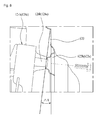
- FIG. 8 illustrates a partial section showing a coupling state of a tub rear and a cabinet rear of a washing machine in accordance with a preferred embodiment of the present invention.
- names of elements are defined taking functions thereof into account. Therefore, it is required to understand that the names do not limit the elements technically. Moreover, the names of the elements may be called differently in this field of art.
- FIG. 1 illustrates an exploded perspective view of a washing machine in accordance with a preferred embodiment of the present invention.
- the washing machine has a tub 10 fixedly secured to a cabinet.
- the tub includes a tub front 100 which forms a front portion thereof and a tub rear 120 which forms a rear portion thereof.
- the tub front 100 and the tub rear 120 are fastened together with screws for forming a space for placing a drum therein.
- the tub also includes a tub back 130 which forms a rear surface thereof.
- the tub back 130 is connected to the tub rear 120 with a rear gasket 250 .
- the rear gasket 250 is formed of a flexible material for preventing vibration from transmitting to the tub rear 120 from the tub back 130 .
- the cabinet 60 forms an exterior of the washing machine.
- the cabinet 60 has a cabinet front (not shown), a cabinet rear 620 , a cabinet left 640 , a cabinet right 640 , a cabinet right 630 , a cabinet top (not shown), and a cabinet base 600 .
- the tub rear 120 has a rear surface 128 .
- the rear surface 128 of the tub rear 120 , the tub back 130 , and the rear gasket 250 form a rear wall surface of the tub 10 .
- the rear gasket 250 is sealably connected to the tub back 130 and the tub rear 120 respectively for preventing the washing water from leaking from the tub 10 .
- the tub back 130 vibrates together with the drum 30 when the drum 30 rotates. In order to prevent the tub back 130 from interfering with the tub rear 120 at the time the tub back 130 vibrates, the tub back 130 is spaced from the tub rear 120 , adequately. Since the rear gasket 250 is formed of a flexible material, the rear gasket 250 allows the tub back 130 to make relative motion without interference with the tub rear 120 .
- the rear gasket 250 may have a corrugated portion 252 (See FIG. 4 ) which can be extended adequately for allowing the relative motion of the tub back 130 .
- a foreign matter getting in preventive member 200 is connected to a front of the tub front 100 for preventing foreign matters from entering between the tub 10 and the drum 30 .
- the foreign matter getting in preventive member 200 is formed of a flexible material, and fixedly mounted to the tub front 100 .
- the foreign matter getting in preventive member 200 may be formed of a material the same with the rear gasket 250 .
- the drum 30 includes a drum front 300 , a drum center 320 , and a drum back 340 .
- the drum front 300 has a laundry opening for introducing the laundry to the drum 30 .
- Ball balancers 310 and 330 are mounted to a front portion and a rear portion of the drum 30 , respectively.
- the drum back 340 is connected to a spider 350 , and the spider 350 is connected to a rotation shaft 351 .
- the drum 30 rotates in the tub by rotation force transmitted thereto through the rotation shaft 351 .
- the rotation shaft 351 is passed through the tub back 130 and connected to the motor in a direct manner. More specifically, a rotor (not shown) of the motor and the rotation shaft 351 are connected, directly. There is a bearing housing 400 coupled to the rear surface 128 of the tub back 130 . The bearing housing 400 rotatably supports the rotation shaft 351 between the motor and the tub back 130 .
- a stator is fixedly mounted to the bearing housing 400 .
- the rotor is positioned around the stator. As described before, the rotor is directly connected to the rotation shaft 351 .
- the motor being an outer rotor type motor, is connected to the rotation shaft 351 , directly.
- the bearing housing 400 is supported on a cabinet base 600 through a suspension assembly 40 (See FIG. 5 ).
- the suspension assembly 40 includes three spring cylinder dampers 500 , 510 and 520 and two cylinder dampers 530 and 540 for supporting in front/rear directions in a tilted positions.
- the suspension assembly 40 is connected to the cabinet base 600 , not fixedly perfectly, but to allow a certain extent of elastic deformation to allow the drum 30 to move in front/rear and left/right directions.
- the suspension assembly 40 is elastically supported to allow a certain extent of rotation of the suspension assembly 40 in front/rear and left/right directions with respect to a supporting point at which the suspension assembly 40 is connected to the base 600 .
- the vertical suspensions may be mounted to the base 600 with rubber bushings disposed therebetween, respectively.
- the vertical suspensions elastically buffer vibration of the drum, and the tilted suspensions dampens the vibration of the drum 30 . That is, it can be configured that, of a vibration system having springs and damping means, ones mounted in vertical positions serve as springs and ones mounted in a tilted positions serve as damping means.
- the tub 10 is fixedly mounted to the cabinet except the tub back 130 , and the vibration of the drum 30 is buffered and supported by the suspension assembly 40 . It can be said that supporting structures for the tub 10 and the drum 30 are separated from each other actually, such that the tub 10 does not vibrate even if the drum 30 vibrates.
- FIGS. 2 and 3 disclose the tub front 100 .
- the tub front 100 has a donut shaped vertical front surface at a front side of a cylindrical surface which is a portion of a sidewall of the tub 10 .
- the front surface has a laundry opening 100 a for introduction of the laundry.
- a rear side of the cylindrical surface is opened the same as an opening of the cylinder of the tub front 100 , and has a plurality of fastening holes 110 .
- the fastening holes 110 are fastened to fastening holes 127 (See FIG. 4 ) in the tub rear 120 matched thereto, respectively.
- a rim portion 101 is extended forward from an inside circumferential surface of a front surface 112 of the tub front 100 .
- the rim portion 101 has a width which becomes the smaller as the rim portion 101 goes from an upper side to a lower side the more. There may not be the rim portion 101 formed on a lower side of an inner edge of the front surface 112 , actually.
- the rim portion 101 has a water supply inlet 104 , a hot air inlet 103 to be used for drying, a circulating water inlet 106 for inlet of washing water circulated by a circulating pump, and a steam inlet 105 for introduction of steam.
- a water supply structure such as the water supply hose for supplying washing water
- a structure for drying such as drying duct
- a structure for supplying steam a structure for supplying the circulating water, and so on can be held in position, securely.
- the hot air inlet 103 is an upward rectangular shaped extension from the rim portion 101 , substantially.
- the hot air inlet 103 is required for a washing and drying machine, and may not be required for a washing machine which has no drying function.
- the water supply inlet 104 , the hot air inlet 103 and so on are formed in the front portion of the tub front 100 , supply of the washing water, the hot air and so on are made at the front side of the tub 10 .
- the water supply inlet 104 and so on can be positioned in front of a front end of the drum 30 which is housed in the tub 10 . Accordingly, the washing water, the hot air and so on can be introduced to the drum 30 directly through the laundry opening provided for laundry in/out. Since fluids which are supplied for treating the laundry, such as the washing water, the hot air and so on, can be introduced to the drum 30 directly, effective treatment of the laundry is possible.
- the water supply inlets 104 and so on are positioned above a center point of the drum.
- the washing water and so on are supplied to the drum 30 from an upper side of the front of the drum. If, different from this, if it is required to supply the washing water and so on to the drum 30 from a lower side of the front of the drum, the rim portion 101 of the tub front 100 may be formed at the lower side of the front surface 112 , accordingly. If it is required to supply the washing water and so on to the drum, not from the upper or lower side, but from a left or right side of the drum, the rim portion 101 can be formed in the vicinity of a center portion of an inside edge of the front surface 112 , accordingly. That is, a shape of the rim portion 101 can vary with a direction of supply of the fluids.
- the coupling portion 102 is a forward extension from a front end of the rim portion 101 to form a small cylindrical surface, substantially.
- the small cylindrical surface has a rib 102 a formed on an outside circumferential surface of the small cylindrical surface.
- the foreign matter getting in preventive member 200 is coupled to the coupling portion 102 as the coupling portion 102 is placed in the foreign matter getting in preventive member 200 . Accordingly, the foreign matter getting in preventive member 200 has a groove (not shown) for placing the small cylindrical surface having the rib 102 a formed therein.
- the tub front 100 is fixedly connected to the cabinet front (not shown).
- fastening bosses 107 a , 107 b , 107 c and 107 d are formed on the front surface of the tub front 100 around the rim portion 101 , substantially.
- FIG. 3 illustrates a perspective view of the tub front 100 seen from a back side thereof.
- the steam inlet 105 can be connected to a steam hose.
- the steam inlet 105 has a steam guide 105 a for guiding the steam introduced thereto to an inside of the drum.
- the circulating water inlet 106 has a circulating water guide 106 a for guiding the circulating water introduced to the circulating water inlet 106 to the inside of the drum.
- the steam inlet 105 , the circulating water inlet 106 , the steam guide 105 a and the circulating water guide 106 a are formed as one unit with the tub front 100 .
- the tub front 100 of plastic is injection molded together with the steam inlet 105 and so on as portions of the tub front 100 .
- the tub front 100 is coupled to the tub rear 120 to form a space for housing the drum 30 .
- the tub front 100 and the tub rear 120 are fastened with screws.
- the tub front 100 has a plurality of screw fastening holes 110 formed along a circumference of a rear portion thereof.
- FIG. 4 illustrates the tub front 100 , the tub rear 120 , the tub back 130 , and the rear gasket 250 assembled together.
- the tub rear 120 is cylindrical to surround the drum 30 , and has an opened front opened as it is, and a donut shaped rear surface 128 .
- the front is sealably coupled to the tub front 100 .
- the rear surface of the tub rear 120 has a diameter adequately greater than the outside diameter of the tub back 130 , so that a gap is formed enough to prevent the tub back 130 from interfering with the rear surface of the tub rear 120 even if the tub back 130 vibrates.
- the rear gasket 250 seals between the rear surface of the tub rear 120 and the tub back 130 .
- the rear gasket 250 has a corrugated portion 252 having an adequate flexibility for not interfering with the vibration of the tub back 130 .
- the tub rear 120 has a hot air outlet 121 on one side for the washing and drying machine. It is natural that the hot air outlet 121 is not required if the washing machine is not the washing and drying machine, but a washing machine only for washing.
- FIG. 5 illustrates a perspective view showing a suspension assembly 40 mounted on the base 600 .
- FIG. 6 illustrates a side view of an assembly of the tub 100 and 120 , the bearing housing 400 , and the suspension assembly 40 .
- the bearing housing 400 includes a bearing supporting portion 401 for supporting the bearings. On a front side of the bearing housing 400 , there is a tub back fastening portion 407 formed thereon. On a rear side of the bearing housing 400 , there is a stator fastening portion 402 formed thereon.
- the suspension assembly 40 includes the bearing housing 400 , a first tilted bracket 431 and a second tilted bracket 430 , and a first suspension bracket 450 and a second suspension bracket 440 .
- first extension 406 a and a second extension 406 b which are extensions from the bearing housing 400 in a radial direction to left and right sides thereof.
- the first extension 406 a and the second extension 406 b have a first tilted bracket 431 and a second tilted bracket 430 connected thereto, respectively.
- the first tilted bracket 431 and the second tilted bracket 430 have the first suspension bracket 450 and the second bracket 440 connected thereto, respectively.
- first extension 406 a , the first tilted bracket 431 , the first suspension bracket 450 and the second extension 440 , the second tilted bracket 430 , the second suspension bracket 440 are symmetry.
- the first, and second tilted brackets 431 and 430 serves to balance a center of gravity of the drum when laundry is introduced to the drum, and as mass in a vibration system in which the drum 30 vibrates.
- the suspension assembly 40 may include a first spring cylinder damper 520 , a second spring cylinder damper 510 , a third spring cylinder damper 500 which are arranged in a vertical direction for vertical direction buffering, and a first cylinder damper 540 and a second cylinder damper 530 arranged in a tilted position for front/rear direction buffering.
- first spring cylinder damper 520 the second spring cylinder damper 510 and the third spring cylinder damper 500
- one may be arranged on a rear side and two may be arranged on left/right sides on a front side of a center of the base 600 .
- the first cylinder damper 540 and the second cylinder damper 530 may be arranged in a front/rear direction on left/right sides with reference to the center in a tilted position.
- first cylinder damper 540 is connected between the first suspension bracket 450 and the base 600 .
- the second spring cylinder damper 510 is connected between the second suspension bracket 440 and the base 600 .
- the third spring cylinder damper 500 is connected between the bearing housing 400 and the base 600 .
- the first cylinder damper 540 is arranged between the first suspension bracket 450 and a rear side of the base in a tilted position
- the second cylinder damper 530 is arranged between the second suspension bracket 440 and the rear side of the base in a tilted position.
- the third spring cylinder damper 500 is arranged at a center of a rear side, and the first cylinder damper 540 and the second spring cylinder damper 510 are arranged on left/right sides of a front side.
- the first cylinder damper 540 and the second spring cylinder damper 510 are positioned on opposite sides of the third spring cylinder damper 500 . That is, the spring dampers 500 , 510 and 520 are arranged symmetry with the cylinder dampers 530 and 540 in left/right directions.
- the tub 10 (specifically, the tub rear 120 ) of the washing machine of the present invention is supported rigidly more than the drum 30 .
- the tub 10 can be supported on the cabinet base 600 by an additional supporter (not shown) and fixedly secured to the cabinet front (not shown) and the cabinet rear 620 , additionally.
- FIG. 7 illustrates a partial section of a rear side of a tub rear of a washing machine in accordance with a preferred embodiment of the present invention
- FIG. 8 illustrates a partial section showing a coupling state of a tub rear and a cabinet rear of a washing machine in accordance with a preferred embodiment of the present invention.
- tub rear 120 and the cabinet rear 620 have fastening structures at predetermined portions thereof respectively for fastening the tub rear 120 to the cabinet rear 620 .
- the tub rear 120 has coupling portions 124 a and 124 b on a rear side projected outward from a body of the tub rear 120 for coupling to the cabinet rear 620 , respectively. That is, the coupling portions 124 a and 124 b are formed on an outer side of an outside circumferential surface of the tub rear 120 . It is preferable that one pair of the coupling portions are provided on left/right sides of an upper side of the tub rear.
- the coupling portions 124 a and 124 b have coupling bosses 126 a and 126 b projected parallel to the tub rear 120 , respectively.
- the tub 10 is secured, not in a horizontal position, but in a tilted position such that a front side of the tub 10 is higher than the rear side of the tub 10 .
- the coupling bosses 126 a and 126 b respectively projected from the coupling portions 124 a and 124 b are projected beyond a rear side of the bearing housing 400 positioned on a rear side of the tub 10 by predetermined distances T, respectively.
- the coupling bosses 126 a and 126 b are projected beyond a rear side of the bearing housing 400 by predetermined distances T thus because the tub 10 is secured more rigidly than the drum 30 and the bearing housing 400 vibrates in association with the vibration of the drum 30 . That is, a space is formed between the cabinet rear 620 having the coupling bosses 126 a and 126 b coupled thereto and the bearing housing 400 for securing a space for the bearing housing 400 to vibrate therein.
- a motor may be mounted in rear of the bearing housing 400 . Therefore, it is preferable that the coupling bosses 126 a and 126 b are formed extended more than the motor, respectively.
- the cabinet rear 620 forms a rear side of the washing machine.
- the cabinet rear 620 has a service panel (not shown) at a center fastened so as to be able to open/close for maintenance of the washing machine separate from the cabinet rear 620 .
- the cabinet rear 620 has securing portions 622 a and 622 b on an upper side spaced from the service panel for fastening to the coupling bosses 126 a and 126 b on the tub rear 120 , respectively.
- the securing portions 622 a and 622 b are projections toward an inside of the cabinet rear 620 , i.e., toward the coupling bosses 126 a and 126 b on the tub rear 120 , respectively. And, the securing portions 622 a and 622 b have end portions sloped by predetermined angles DA as much as the tilting angles of the coupling bosses 126 a and 126 b on the tub rear 120 , respectively. In this instance, it is preferable that the predetermined angles of the end portions of the securing portions 622 a and 622 b are the same with the tilting angles of the tub 10 . Eventually, the tub rear 120 positioned tilted by the predetermined angle and the cabinet rear 620 and the cabinet rear 620 mounted in a vertical position can be fastened together, closely.
Abstract
Description
Claims (6)
Applications Claiming Priority (7)
| Application Number | Priority Date | Filing Date | Title |
|---|---|---|---|
| KR20090047192 | 2009-05-28 | ||
| KR10-2009-0047192 | 2009-05-28 | ||
| KR10-2009-0079909 | 2009-08-27 | ||
| KR20090079909 | 2009-08-27 | ||
| KR10-2010-0046463 | 2010-05-18 | ||
| KR1020100046463A KR101644885B1 (en) | 2009-05-28 | 2010-05-18 | washing machine |
| PCT/KR2010/003409 WO2010137912A2 (en) | 2009-05-28 | 2010-05-28 | Washing machine |
Publications (2)
| Publication Number | Publication Date |
|---|---|
| US20120024020A1 US20120024020A1 (en) | 2012-02-02 |
| US9422657B2 true US9422657B2 (en) | 2016-08-23 |
Family
ID=43505908
Family Applications (3)
| Application Number | Title | Priority Date | Filing Date |
|---|---|---|---|
| US13/259,709 Abandoned US20120031150A1 (en) | 2009-05-28 | 2010-05-27 | Laundry machine |
| US13/259,754 Active 2033-05-13 US9284677B2 (en) | 2009-05-28 | 2010-05-27 | Laundry machine |
| US13/259,016 Active 2032-11-25 US9422657B2 (en) | 2009-05-28 | 2010-05-28 | Washing machine |
Family Applications Before (2)
| Application Number | Title | Priority Date | Filing Date |
|---|---|---|---|
| US13/259,709 Abandoned US20120031150A1 (en) | 2009-05-28 | 2010-05-27 | Laundry machine |
| US13/259,754 Active 2033-05-13 US9284677B2 (en) | 2009-05-28 | 2010-05-27 | Laundry machine |
Country Status (6)
| Country | Link |
|---|---|
| US (3) | US20120031150A1 (en) |
| EP (3) | EP2435611B1 (en) |
| KR (5) | KR20100129161A (en) |
| CN (3) | CN102428224B (en) |
| ES (1) | ES2505494T3 (en) |
| WO (3) | WO2010137895A1 (en) |
Cited By (1)
| Publication number | Priority date | Publication date | Assignee | Title |
|---|---|---|---|---|
| US11859334B2 (en) | 2020-12-09 | 2024-01-02 | Samsung Electronics Co., Ltd. | Washing machine |
Families Citing this family (19)
| Publication number | Priority date | Publication date | Assignee | Title |
|---|---|---|---|---|
| EP1809805B1 (en) * | 2004-11-10 | 2014-10-22 | LG Electronics Inc. | Dryer |
| KR20100080415A (en) | 2008-12-30 | 2010-07-08 | 엘지전자 주식회사 | Laundry machine |
| KR20100129161A (en) | 2009-05-28 | 2010-12-08 | 엘지전자 주식회사 | Laundry machine |
| KR101692727B1 (en) | 2009-05-28 | 2017-01-04 | 엘지전자 주식회사 | Laundry machine |
| US9828715B2 (en) | 2009-05-28 | 2017-11-28 | Lg Electronics Inc. | Laundry maching having a drying function |
| KR101663610B1 (en) | 2009-05-28 | 2016-10-07 | 엘지전자 주식회사 | Laundry Machine |
| KR101689604B1 (en) * | 2009-05-28 | 2017-01-09 | 엘지전자 주식회사 | Laundry machine |
| KR101871271B1 (en) | 2011-12-09 | 2018-06-27 | 엘지전자 주식회사 | Washing machine |
| CN104514121B (en) * | 2013-09-27 | 2017-12-05 | 博西华电器(江苏)有限公司 | Roller washing machine with transit bolt |
| KR101645425B1 (en) * | 2014-07-15 | 2016-08-04 | 동부대우전자 주식회사 | The washing machine and manufacturing method thereof |
| KR101588137B1 (en) * | 2014-10-24 | 2016-01-22 | 엘지전자 주식회사 | Drain pump assembly and dryer for clothes having the same |
| DE202015101403U1 (en) | 2015-03-19 | 2015-03-26 | Antonio Chiriatti | Machine for washing clothes or drying clothes |
| KR102436709B1 (en) * | 2015-09-30 | 2022-08-26 | 엘지전자 주식회사 | Washing machine |
| TR201512512A2 (en) * | 2015-10-08 | 2017-04-21 | Arcelik As | A WASHING WASHER - DRYER PREVENTING THE BOILER TO BODY |
| US10053808B2 (en) * | 2015-12-01 | 2018-08-21 | Whirlpool Corporation | Laundry treating appliance |
| KR102572272B1 (en) | 2016-08-25 | 2023-08-29 | 엘지전자 주식회사 | A Laundry Apparatus |
| US10941511B2 (en) | 2016-08-25 | 2021-03-09 | Lg Electronics Inc. | Clothes treatment apparatus and control method therefor |
| KR20180074484A (en) * | 2016-12-23 | 2018-07-03 | 삼성전자주식회사 | Washing machine |
| EP3936654A1 (en) * | 2020-07-10 | 2022-01-12 | Electrolux Appliances Aktiebolag | Washing machine comprising a supporting element for a water heater |
Citations (167)
| Publication number | Priority date | Publication date | Assignee | Title |
|---|---|---|---|---|
| US1593678A (en) | 1924-11-13 | 1926-07-27 | Clewell E Statler | Carpet and rug cleaning machine |
| US2856699A (en) | 1956-08-06 | 1958-10-21 | Gen Motors Corp | Clothes drier with condenser |
| GB913801A (en) | 1961-07-26 | 1962-12-28 | Mc Graw Edison Co | Laundry machine |
| US3275152A (en) | 1960-01-19 | 1966-09-27 | Hoover Co | Suspension system for centrifugal extractors |
| US3387310A (en) | 1966-09-22 | 1968-06-11 | Donald E. Marshall | Washing apparatus and method |
| GB1181797A (en) | 1958-12-12 | 1970-02-18 | Gen Motors France | Clothes Washer Machines |
| US3509742A (en) | 1966-10-05 | 1970-05-05 | Fritz Bauer | Supporting structure for a washing machine |
| DE2503576A1 (en) | 1974-09-21 | 1976-08-05 | Licentia Gmbh | LAUNDRY MACHINE |
| US4033047A (en) | 1974-08-07 | 1977-07-05 | Tokyo Shibaura Electric Co., Ltd. | Clothes dryer |
| JPS52131661A (en) | 1976-04-27 | 1977-11-04 | Mitsubishi Electric Corp | Automatic washing machine |
| US4204339A (en) | 1978-02-17 | 1980-05-27 | August Lepper, Maschinen-U. Apparatebau GmbH | Tumbler washing and drying machine |
| GB2091123A (en) | 1980-12-09 | 1982-07-28 | Bauknecht Gmbh G | Filter for clothes dryer |
| EP0152745A2 (en) | 1984-02-13 | 1985-08-28 | INDUSTRIE ZANUSSI S.p.A. | Plastic tub for a laundry washing machine |
| DE3438575A1 (en) | 1984-10-20 | 1986-04-30 | Herbert Kannegiesser Gmbh + Co, 4973 Vlotho | Appliance for the drying of laundry |
| US4891892A (en) | 1983-12-15 | 1990-01-09 | Narang Rajendra K | Clothes dryer and laundry system |
| US4899462A (en) | 1988-10-14 | 1990-02-13 | Speed Queen Company | Lint burning clothes dryer |
| EP0443361A1 (en) | 1990-02-20 | 1991-08-28 | INDUSTRIE ZANUSSI S.p.A. | Fluff filter monitoring device for laundry driers |
| DE4104450A1 (en) | 1991-02-14 | 1992-08-20 | Manfred Stoll | Washing textiles in automatic washing machine - by using twin drum principle and recycling container to store solns. |
| US5231805A (en) | 1991-07-01 | 1993-08-03 | Sander James P | Surface cleaning and asbestos removal machine |
| US5259218A (en) | 1991-09-19 | 1993-11-09 | Ellis Corporation | Force minimizing suspension system for rotary washer/extractors |
| DE4413069A1 (en) | 1993-04-26 | 1994-10-27 | Electrolux Ab | Device on a washing machine for damping the vibration noise |
| GB2279968A (en) | 1993-06-17 | 1995-01-18 | Hoover Ltd | Suspension unit with damped second spring |
| EP0648885A1 (en) | 1993-10-15 | 1995-04-19 | Esswein S.A. | Device for cleaning the filter of a machine's drying system |
| JPH07124382A (en) | 1993-10-29 | 1995-05-16 | Toshiba Corp | Washing machine |
| JPH07275591A (en) | 1994-04-07 | 1995-10-24 | Hitachi Ltd | Clothes drying machine |
| US5582040A (en) | 1995-08-09 | 1996-12-10 | Khan; Aman U. | Water balancing apparatus for horizontal axis and vertical axis laundry appliances |
| RU2085641C1 (en) | 1994-12-07 | 1997-07-27 | Александр Иванович Смирнов | Washing-squeezing machine |
| DE29716968U1 (en) | 1996-09-24 | 1997-11-06 | Electrolux Zanussi Elettrodome | Washing machine or similar with a drum rotatable about a horizontal axis |
| US5711170A (en) | 1994-08-19 | 1998-01-27 | Maytag Corporation | Integrated tub and cabinet structure |
| US5735006A (en) | 1996-06-05 | 1998-04-07 | Maytag Corporation | Washing machine pulley and fluid ring |
| CN1179489A (en) | 1996-08-21 | 1998-04-22 | 博施-西门子家用器具有限公司 | Washer with plastic rinsing container |
| JPH10211393A (en) | 1997-01-30 | 1998-08-11 | Matsushita Electric Ind Co Ltd | Drum washing machine |
| CN1208787A (en) | 1997-08-16 | 1999-02-24 | 三星电子株式会社 | Filter for washing machine |
| DE19856973A1 (en) | 1997-12-11 | 1999-06-24 | Lg Electronics Inc | Washing machine drum |
| KR20000056255A (en) | 1999-02-18 | 2000-09-15 | 윤종용 | wash aligning apparatus and operating method for drum washing machine |
| EP1079014A1 (en) | 1999-03-15 | 2001-02-28 | Kabushiki Kaisha Toshiba | Drum type washing machine |
| US6256823B1 (en) | 1999-06-29 | 2001-07-10 | The Chardon Rubber Company | Bellows for front loading washing machines |
| WO2001096647A1 (en) | 2000-05-24 | 2001-12-20 | Electrolux Nyborg A/S | Tumbler drier with a filter device |
| RU2182197C2 (en) | 1997-04-24 | 2002-05-10 | Мирамонди С.Р.Л. | Improved drum unit for washing and drying machines and method for manufacture thereof |
| KR20020056323A (en) | 2000-12-29 | 2002-07-10 | 구자홍 | Connecting device between tub and door gasket for washing machine |
| KR20020091795A (en) | 2001-05-30 | 2002-12-06 | 산요 덴키 가부시키가이샤 | Drum-type washing machine |
| EP1270791A2 (en) | 2001-06-21 | 2003-01-02 | Lg Electronics Inc. | Balance weight in drum type washing machine and manufacturing method thereof |
| JP2003245489A (en) | 2002-02-26 | 2003-09-02 | Toshiba Corp | Washing and drying machine |
| KR20030092185A (en) | 2002-05-27 | 2003-12-06 | 엘지전자 주식회사 | The heater mounting of a drum washer |
| JP2004000806A (en) | 2003-09-29 | 2004-01-08 | Sanyo Electric Co Ltd | Drum type washing machine |
| JP3502039B2 (en) | 2000-03-11 | 2004-03-02 | エルジー電子株式会社 | Washing machine with balancer |
| KR20040046973A (en) | 2002-11-28 | 2004-06-05 | 엘지전자 주식회사 | A water level sensing apparatus of washer |
| US20040107742A1 (en) | 2002-11-29 | 2004-06-10 | Jae Kyum Kim | Gasket and washing machine using the same |
| EP1433890A2 (en) | 2002-12-27 | 2004-06-30 | Lg Electronics Inc. | Drum type washing machine |
| CN1508349A (en) | 2002-12-17 | 2004-06-30 | 乐金电子(天津)电器有限公司 | Inclined drum washing machine |
| US20040148978A1 (en) | 2002-09-26 | 2004-08-05 | Kim Kwang Soo | Drum-type washing machine |
| EP1445368A2 (en) | 2003-02-04 | 2004-08-11 | Merloni Elettrodomestici S.p.A. | Laundry washing machine, in particular a front loading washing machine, with a washing agents dispenser |
| US20040163426A1 (en) | 2002-11-29 | 2004-08-26 | Kim Jong Seok | Tilted drum type washing machine |
| CN1540085A (en) | 2003-04-25 | 2004-10-27 | Lg������ʽ���� | Washing water cycling device for washing machine and its control method |
| US20040221474A1 (en) | 2003-05-05 | 2004-11-11 | Dennis Slutsky | Combination washer/dryer having common heat source |
| US20040226321A1 (en) | 2003-05-15 | 2004-11-18 | Gwan-Ryong Park | Variable damping type damper and washing machine having the same |
| DE10342254B3 (en) | 2003-09-11 | 2004-11-18 | Miele & Cie. Kg | Washing machine has seal between shaft pin supporting laundry drum and opening in base of washing liquid container with integral part of washing liquid container base shielding seal from contact with washing liquid |
| CN1548627A (en) | 2003-05-12 | 2004-11-24 | 乐金电子(天津)电器有限公司 | Heater support structure for tumble washer |
| US20040261469A1 (en) | 2003-05-13 | 2004-12-30 | Park Seung Chul | Damper for washing machine |
| KR20050006330A (en) | 2003-07-08 | 2005-01-17 | 엘지전자 주식회사 | Structure of Tub in drum-type washing machine |
| WO2005017249A1 (en) | 2003-08-15 | 2005-02-24 | Arcelik Anonim Sirketi | A washer/dryer with a drum having one or more filters |
| KR20050022659A (en) | 2003-08-29 | 2005-03-08 | 엘지전자 주식회사 | Apparatus for mounting Dryer for washig machine |
| EP1529869A2 (en) | 2003-11-07 | 2005-05-11 | Matsushita Electric Industrial Co., Ltd. | Drum type washing machine |
| US20050120715A1 (en) | 1997-12-23 | 2005-06-09 | Christion School Of Technology Charitable Foundation Trust | Heat energy recapture and recycle and its new applications |
| US20050183472A1 (en) | 2004-02-25 | 2005-08-25 | Choi Kang M. | Damper assembly and washing machine using the same |
| US6941680B1 (en) | 2003-07-03 | 2005-09-13 | Robert Zielewicz | Cost-efficient clothes dryer |
| KR20050108609A (en) | 2004-05-12 | 2005-11-17 | 주식회사 대우일렉트로닉스 | Suspension for washing machine |
| US20050262879A1 (en) | 2004-06-01 | 2005-12-01 | Lg Electronics Inc. | Washing machine |
| EP1605088A2 (en) | 2004-06-09 | 2005-12-14 | Lg Electronics Inc. | Drum type washing machine and drum therefor |
| US20060010935A1 (en) | 2004-07-13 | 2006-01-19 | Lg Electronics Inc. | Damper and washing machine having the damper |
| CN1724742A (en) | 2004-07-20 | 2006-01-25 | Lg电子株式会社 | Drum type washing machine and bearing housing structure thereof |
| CN1730776A (en) | 2004-08-06 | 2006-02-08 | 乐金电子(天津)电器有限公司 | Gasket of drum washing machine |
| CN1730777A (en) | 2004-08-06 | 2006-02-08 | 乐金电子(天津)电器有限公司 | Gasket of drum washing machine |
| CN1730778A (en) | 2004-08-06 | 2006-02-08 | 乐金电子(天津)电器有限公司 | Gasket of drum washing machine with drying function |
| JP2006061613A (en) | 2004-08-30 | 2006-03-09 | Toshiba Corp | Drum type washing machine |
| US20060053838A1 (en) | 2004-09-13 | 2006-03-16 | Matsushita Electric Industrial Co., Ltd. | Drum type washing machine |
| US7020985B2 (en) | 2004-03-26 | 2006-04-04 | Whirlpool Corporation | Multiple outlet air path for a clothes dryer |
| US7020986B1 (en) | 2004-11-11 | 2006-04-04 | Matsushita Electric Industrial Co., Ltd. | Drum type washing and drying machine |
| US20060075791A1 (en) | 2004-10-07 | 2006-04-13 | Lg Electronics Inc. | Washing machine |
| KR20060046969A (en) | 2004-11-12 | 2006-05-18 | 주식회사 대우일렉트로닉스 | A door gasket for drum washing machine |
| US20060101865A1 (en) | 2004-11-04 | 2006-05-18 | Lg Electronics Inc. | Washing machine |
| US20060169006A1 (en) | 2005-02-03 | 2006-08-03 | Lg Electronics Inc. | Drum type washing machine |
| EP1688524A1 (en) | 2005-02-03 | 2006-08-09 | Lg Electronics Inc. | Washing-drying/drying machine with a condensing device |
| EP1688525A1 (en) | 2005-02-05 | 2006-08-09 | Samsung Electronics Co, Ltd | Drum washing machine with balance weight |
| US20060174663A1 (en) | 2005-02-10 | 2006-08-10 | Electrolux Home Products Corporation N.V. | Front flange of a household-type clothes washing machine |
| KR20060095816A (en) | 2005-02-28 | 2006-09-04 | 엘지전자 주식회사 | Coupling structure for transit bolt of drum-washer tub |
| CN1844543A (en) | 2005-04-06 | 2006-10-11 | 三星电子株式会社 | Drum washing machine |
| EP1722025A1 (en) | 2005-05-11 | 2006-11-15 | LG Electronics Inc. | Washing machine |
| KR100651853B1 (en) | 2005-09-30 | 2006-12-01 | 엘지전자 주식회사 | Bearing housing assembly of an insert-molding type and cabinet-tub unified drum-washer having the same |
| EP1746195A2 (en) | 2003-03-31 | 2007-01-24 | Lg Electronics Inc. | Steam jet drum washing machine |
| CN1906351A (en) | 2004-04-20 | 2007-01-31 | Lg电子株式会社 | Drum washing machine |
| DE102006012035B3 (en) | 2006-03-14 | 2007-03-01 | Miele & Cie. Kg | Wash container for a horizontal axis front-loading washing machine has plate heater for the wash fluid sealed beneath the container with support and clamps |
| US20070051142A1 (en) | 2005-09-08 | 2007-03-08 | Lg Electronics Inc. | Drum type washing machine |
| KR20070059431A (en) | 2005-12-06 | 2007-06-12 | 엘지전자 주식회사 | Back cover mounting structure for wash machine |
| KR100730919B1 (en) | 2004-12-03 | 2007-06-22 | 주식회사 대우일렉트로닉스 | Tub fixing device for drum type washing machine |
| RU2303092C1 (en) | 2005-11-07 | 2007-07-20 | ГОУ ВПО "Южно-Российский государственный университет экономики и сервиса" (ЮРГУЭС) | Washing machine |
| RU2303668C2 (en) | 2004-08-26 | 2007-07-27 | Мацусита Электрик Индастриал Ко., Лтд. | Washing machine |
| KR20070078602A (en) | 2006-01-27 | 2007-08-01 | 엘지전자 주식회사 | Tub for washing machine and manufacturing method for the same |
| WO2007105843A1 (en) | 2006-03-16 | 2007-09-20 | Lg Electronics Inc. | Top-loading drum type washing machine |
| CN101046046A (en) | 2006-03-29 | 2007-10-03 | Lg电子株式会社 | Drum type washing machine |
| EP1840257A1 (en) | 2006-03-29 | 2007-10-03 | LG Electronics Ltd. | Drum type washing machine |
| KR20070101732A (en) | 2006-04-12 | 2007-10-17 | 엘지전자 주식회사 | Drum washer |
| KR20070101688A (en) | 2006-04-12 | 2007-10-17 | 엘지전자 주식회사 | Washing machine |
| JP2007282962A (en) | 2006-04-19 | 2007-11-01 | Hitachi Appliances Inc | Drum type washing machine or drum type washing/drying machine |
| EP1857583A1 (en) | 2006-05-19 | 2007-11-21 | Whirlpool Corporation | Dynamic load detection for a clothes washer |
| US20070289339A1 (en) | 2006-06-09 | 2007-12-20 | Lim Hee T | Mechanical apparatus for washing/drying |
| KR20080002475A (en) | 2006-06-30 | 2008-01-04 | 주식회사 대우일렉트로닉스 | Tremor preventing device of washing machine |
| WO2008003592A1 (en) | 2006-07-06 | 2008-01-10 | BSH Bosch und Siemens Hausgeräte GmbH | Front loading washing machine |
| JP2008006045A (en) | 2006-06-29 | 2008-01-17 | Matsushita Electric Ind Co Ltd | Washing/drying machine |
| WO2008007888A2 (en) | 2006-07-10 | 2008-01-17 | Lg Electronics Inc. | Laundry machine and controlling method thereof |
| EP1881099A1 (en) | 2005-05-13 | 2008-01-23 | Sharp Kabushiki Kaisha | Drum type washing machine |
| KR20080018747A (en) | 2006-08-25 | 2008-02-28 | 엘지전자 주식회사 | Washing machine |
| US20080099052A1 (en) | 2006-11-01 | 2008-05-01 | Samsung Electronics Co., Ltd. | Washing machine and washing control method of the same |
| US7398662B2 (en) | 2002-11-29 | 2008-07-15 | Lg Electronics Inc. | Gasket and washing machine using the same |
| KR20080072187A (en) | 2007-02-01 | 2008-08-06 | 엘지전자 주식회사 | Laundry treatment machine |
| WO2008103007A2 (en) | 2007-02-23 | 2008-08-28 | Lg Electronics Inc. | Drum type washing machine |
| EP1975298A1 (en) | 2007-03-27 | 2008-10-01 | Samsung Electronics Co., Ltd. | Washer |
| KR20080095565A (en) | 2007-04-25 | 2008-10-29 | 엘지전자 주식회사 | Washer |
| JP2008259665A (en) | 2007-04-12 | 2008-10-30 | Sharp Corp | Drum type washing/drying machine |
| US20080276656A1 (en) | 2005-07-28 | 2008-11-13 | Sharp Kabushiki Kaisha | Drum Type Drying and Washing Machine |
| US7458171B1 (en) | 2007-01-29 | 2008-12-02 | Lentz Luke E | Dehumidifier clothes dryer apparatus |
| JP2009028400A (en) | 2007-07-30 | 2009-02-12 | Panasonic Corp | Washing machine |
| US20090056389A1 (en) | 2007-08-31 | 2009-03-05 | Whirlpool Corporation | Fabric Treatment Appliance with Steam Generator Having a Variable Thermal Output |
| CN101381946A (en) | 2007-09-09 | 2009-03-11 | 唐红元 | Magnetic suspension drum-type washing machine |
| EP2039819A1 (en) | 2007-09-21 | 2009-03-25 | CANDY S.p.A. | Washer-drier machine |
| JP2009061217A (en) | 2007-09-10 | 2009-03-26 | Toshiba Corp | Clothes drying machine |
| JP2009060990A (en) | 2007-09-05 | 2009-03-26 | Panasonic Corp | Washing machine |
| WO2009040302A1 (en) | 2007-09-20 | 2009-04-02 | BSH Bosch und Siemens Hausgeräte GmbH | Plastic suds tub for a washing machine or a washer/dryer |
| WO2009050095A1 (en) | 2007-10-18 | 2009-04-23 | BSH Bosch und Siemens Hausgeräte GmbH | Washing machine having a gasket |
| EP2053157A1 (en) | 2007-10-18 | 2009-04-29 | Electrolux Home Products Corporation N.V. | Dry-washing machine employing a wash fluid and equipped with a combination filter assembly |
| EP2075364A1 (en) | 2007-12-27 | 2009-07-01 | Daewoo Electronics Corporation | Washing machine |
| EP2078777A1 (en) | 2008-01-14 | 2009-07-15 | Electrolux Home Products Corporation N.V. | Laundry machine with an improved bellows |
| CN100513673C (en) | 2004-05-12 | 2009-07-15 | 株式会社大宇电子 | Washing machine with a drying device |
| US20090178442A1 (en) | 2005-11-18 | 2009-07-16 | Shinichiro Kawabata | Washing and drying machine |
| US20090178445A1 (en) | 2008-01-15 | 2009-07-16 | Miele & Cie. Kg | Front-loading drum-type washing machine having a laundry deflector |
| FR2931489A1 (en) | 2008-05-20 | 2009-11-27 | Fagorbrandt Sas | Linen fluff removing method for front load clothes drying machine, involves scraping fluff on fluff filter using scraping unit when fan is operated in inversed rotation direction during drying cycle of clothes |
| WO2009148251A2 (en) | 2008-06-03 | 2009-12-10 | (주)엘지전자 | Clothes dryer |
| CN101343826B (en) | 2008-01-23 | 2010-08-11 | 松下家电研究开发(杭州)有限公司 | Washing machine with drying device |
| US20100306928A1 (en) | 2009-06-03 | 2010-12-09 | Green Solution, Inc. | Method and Apparatus for Using Steam in a Commercial Laundry Machine as an Environmentally-Friendly Replacement of Conventional Dry Cleaning or Wet Cleaning Processes |
| CN101173482B (en) | 2006-10-31 | 2011-05-25 | 海尔集团公司 | Scraps filtering device of heat pump washing machine drier |
| US20110173834A1 (en) | 2008-07-14 | 2011-07-21 | Electrolux Home Products Corporation, N.V. | Laundry Drying Machine with Vibrating Fluff Filter |
| US8028439B2 (en) | 2007-09-28 | 2011-10-04 | Mabe Canada Inc. | Clothes dryer bearing gasket support |
| EP2390401A2 (en) | 2008-12-31 | 2011-11-30 | LG Electronics Inc. | Laundry machine |
| US20120000087A1 (en) | 2008-12-30 | 2012-01-05 | Electrolux Home Products Corporation N.V. | Household Appliance for Drying Garments |
| EP2435624A2 (en) | 2009-05-28 | 2012-04-04 | LG Electronics Inc. | Laundry machine |
| US20120090189A1 (en) | 2009-05-28 | 2012-04-19 | Kwon Ig Geun | Laundry machine having a drying function |
| US8201345B2 (en) | 2008-07-02 | 2012-06-19 | Whirlpool Corporation | Method for operating a cleanout cycle in a dispensing dryer |
| US8256137B2 (en) | 2007-07-13 | 2012-09-04 | Electrolux Home Products Corporation N.V. | Determining clog steam generator tank filter laundry drier, and apparatus |
| US20130091726A1 (en) | 2011-10-13 | 2013-04-18 | Youngsuk Kim | Clothes treatment apparatus and method for controlling a clothes treatment apparatus |
| US8438750B2 (en) | 2008-09-11 | 2013-05-14 | Bsh Bosch Und Siemens Hausgeraete Gmbh | Dryer having a lint filter and a cleaning device |
| US20130139402A1 (en) | 2010-08-19 | 2013-06-06 | Sangwook Hong | Laundry machine having a drying function, and method for controlling same |
| US8490294B2 (en) | 2006-02-17 | 2013-07-23 | Bsh Bosch Und Siemens Hausgeraete Gmbh | Cleaning device for a component of a household washer-dryer |
| US20130205840A1 (en) | 2010-10-19 | 2013-08-15 | Sangwook Hong | Washing machine having drying function |
| US20130219734A1 (en) | 2012-02-29 | 2013-08-29 | Youngsuk Kim | Laundry treating machine |
| US20130255099A1 (en) | 2012-04-02 | 2013-10-03 | Electrolux Home Products Corporation N.V. | Dryer with Air Recirculation/Heat Exchange Subassembly |
| US20130263630A1 (en) | 2012-04-06 | 2013-10-10 | Youngjin DOH | Laundry treating machine |
| US20130291395A1 (en) | 2012-05-03 | 2013-11-07 | Youngjin DOH | Laundry treating machine and control method thereof |
| US20130318813A1 (en) | 2011-04-05 | 2013-12-05 | Sangwook Hong | Laundry machine and method for cleaning lint filter of laundry machine |
| US8607473B2 (en) | 2008-06-03 | 2013-12-17 | Lg Electronics Inc. | Dryer door and dryer comprising the same |
| US8615895B2 (en) | 2010-05-13 | 2013-12-31 | Samsung Electronics Co., Ltd. | Clothes dryer |
| US8627581B2 (en) | 2007-08-23 | 2014-01-14 | Michael E. Brown | Heat delivery system for a fabric care appliance |
| US8627580B2 (en) | 2009-09-29 | 2014-01-14 | Lg Electronics Inc. | Dryer |
| US8661707B2 (en) | 2003-05-23 | 2014-03-04 | Bsh Bosch Und Siemens Hausgeraete Gmbh | Laundry drier |
| US8667705B2 (en) | 2010-10-12 | 2014-03-11 | Samsung Electronics Co., Ltd. | Clothes dryer and lint cleaning device thereof |
| US20140208609A1 (en) | 2013-01-25 | 2014-07-31 | Injae Han | Laundry treatment apparatus |
| US8863401B2 (en) | 2009-04-21 | 2014-10-21 | Bsh Bosch Und Siemens Hausgeraete Gmbh | Household laundry dryer condensate filtering apparatus and method |
| US8984767B2 (en) | 2009-03-13 | 2015-03-24 | BSH Hausgeräte GmbH | Laundry drying unit having a lint screen arranged within a process air circuit and a method for operating said laundry drying unit |
Family Cites Families (1)
| Publication number | Priority date | Publication date | Assignee | Title |
|---|---|---|---|---|
| JP2004344373A (en) * | 2003-05-22 | 2004-12-09 | Matsushita Electric Ind Co Ltd | Drum type washing and drying machine |
-
2010
- 2010-05-18 KR KR1020100046459A patent/KR20100129161A/en not_active Application Discontinuation
- 2010-05-18 KR KR1020100046461A patent/KR101644884B1/en active IP Right Grant
- 2010-05-18 KR KR1020100046463A patent/KR101644885B1/en active IP Right Grant
- 2010-05-18 KR KR1020100046458A patent/KR101689600B1/en active IP Right Grant
- 2010-05-20 KR KR1020100047412A patent/KR101714438B1/en active IP Right Grant
- 2010-05-27 EP EP10780806.5A patent/EP2435611B1/en active Active
- 2010-05-27 US US13/259,709 patent/US20120031150A1/en not_active Abandoned
- 2010-05-27 CN CN201080022490.5A patent/CN102428224B/en active Active
- 2010-05-27 WO PCT/KR2010/003379 patent/WO2010137895A1/en active Application Filing
- 2010-05-27 US US13/259,754 patent/US9284677B2/en active Active
- 2010-05-27 WO PCT/KR2010/003378 patent/WO2010137894A2/en active Application Filing
- 2010-05-27 CN CN2010800212594A patent/CN102421951A/en active Pending
- 2010-05-27 EP EP10780805.7A patent/EP2435624B1/en active Active
- 2010-05-28 CN CN201080017293.4A patent/CN102395724B/en active Active
- 2010-05-28 EP EP10780823.0A patent/EP2435617B1/en active Active
- 2010-05-28 ES ES10780823.0T patent/ES2505494T3/en active Active
- 2010-05-28 WO PCT/KR2010/003409 patent/WO2010137912A2/en active Application Filing
- 2010-05-28 US US13/259,016 patent/US9422657B2/en active Active
Patent Citations (199)
| Publication number | Priority date | Publication date | Assignee | Title |
|---|---|---|---|---|
| US1593678A (en) | 1924-11-13 | 1926-07-27 | Clewell E Statler | Carpet and rug cleaning machine |
| US2856699A (en) | 1956-08-06 | 1958-10-21 | Gen Motors Corp | Clothes drier with condenser |
| GB1181797A (en) | 1958-12-12 | 1970-02-18 | Gen Motors France | Clothes Washer Machines |
| US3275152A (en) | 1960-01-19 | 1966-09-27 | Hoover Co | Suspension system for centrifugal extractors |
| GB913801A (en) | 1961-07-26 | 1962-12-28 | Mc Graw Edison Co | Laundry machine |
| US3387310A (en) | 1966-09-22 | 1968-06-11 | Donald E. Marshall | Washing apparatus and method |
| US3509742A (en) | 1966-10-05 | 1970-05-05 | Fritz Bauer | Supporting structure for a washing machine |
| US4033047A (en) | 1974-08-07 | 1977-07-05 | Tokyo Shibaura Electric Co., Ltd. | Clothes dryer |
| DE2503576A1 (en) | 1974-09-21 | 1976-08-05 | Licentia Gmbh | LAUNDRY MACHINE |
| JPS52131661A (en) | 1976-04-27 | 1977-11-04 | Mitsubishi Electric Corp | Automatic washing machine |
| US4204339A (en) | 1978-02-17 | 1980-05-27 | August Lepper, Maschinen-U. Apparatebau GmbH | Tumbler washing and drying machine |
| GB2091123A (en) | 1980-12-09 | 1982-07-28 | Bauknecht Gmbh G | Filter for clothes dryer |
| US4891892A (en) | 1983-12-15 | 1990-01-09 | Narang Rajendra K | Clothes dryer and laundry system |
| EP0152745A2 (en) | 1984-02-13 | 1985-08-28 | INDUSTRIE ZANUSSI S.p.A. | Plastic tub for a laundry washing machine |
| DE3438575A1 (en) | 1984-10-20 | 1986-04-30 | Herbert Kannegiesser Gmbh + Co, 4973 Vlotho | Appliance for the drying of laundry |
| US4899462A (en) | 1988-10-14 | 1990-02-13 | Speed Queen Company | Lint burning clothes dryer |
| EP0443361A1 (en) | 1990-02-20 | 1991-08-28 | INDUSTRIE ZANUSSI S.p.A. | Fluff filter monitoring device for laundry driers |
| DE4104450A1 (en) | 1991-02-14 | 1992-08-20 | Manfred Stoll | Washing textiles in automatic washing machine - by using twin drum principle and recycling container to store solns. |
| US5231805A (en) | 1991-07-01 | 1993-08-03 | Sander James P | Surface cleaning and asbestos removal machine |
| US5259218A (en) | 1991-09-19 | 1993-11-09 | Ellis Corporation | Force minimizing suspension system for rotary washer/extractors |
| DE4413069A1 (en) | 1993-04-26 | 1994-10-27 | Electrolux Ab | Device on a washing machine for damping the vibration noise |
| GB2279968A (en) | 1993-06-17 | 1995-01-18 | Hoover Ltd | Suspension unit with damped second spring |
| EP0648885A1 (en) | 1993-10-15 | 1995-04-19 | Esswein S.A. | Device for cleaning the filter of a machine's drying system |
| JPH07124382A (en) | 1993-10-29 | 1995-05-16 | Toshiba Corp | Washing machine |
| JPH07275591A (en) | 1994-04-07 | 1995-10-24 | Hitachi Ltd | Clothes drying machine |
| US5711170A (en) | 1994-08-19 | 1998-01-27 | Maytag Corporation | Integrated tub and cabinet structure |
| RU2085641C1 (en) | 1994-12-07 | 1997-07-27 | Александр Иванович Смирнов | Washing-squeezing machine |
| US5582040A (en) | 1995-08-09 | 1996-12-10 | Khan; Aman U. | Water balancing apparatus for horizontal axis and vertical axis laundry appliances |
| US5735006A (en) | 1996-06-05 | 1998-04-07 | Maytag Corporation | Washing machine pulley and fluid ring |
| CN1179489A (en) | 1996-08-21 | 1998-04-22 | 博施-西门子家用器具有限公司 | Washer with plastic rinsing container |
| DE29716968U1 (en) | 1996-09-24 | 1997-11-06 | Electrolux Zanussi Elettrodome | Washing machine or similar with a drum rotatable about a horizontal axis |
| JPH10211393A (en) | 1997-01-30 | 1998-08-11 | Matsushita Electric Ind Co Ltd | Drum washing machine |
| RU2182197C2 (en) | 1997-04-24 | 2002-05-10 | Мирамонди С.Р.Л. | Improved drum unit for washing and drying machines and method for manufacture thereof |
| CN1208787A (en) | 1997-08-16 | 1999-02-24 | 三星电子株式会社 | Filter for washing machine |
| DE19856973A1 (en) | 1997-12-11 | 1999-06-24 | Lg Electronics Inc | Washing machine drum |
| US20050120715A1 (en) | 1997-12-23 | 2005-06-09 | Christion School Of Technology Charitable Foundation Trust | Heat energy recapture and recycle and its new applications |
| KR20000056255A (en) | 1999-02-18 | 2000-09-15 | 윤종용 | wash aligning apparatus and operating method for drum washing machine |
| KR20010071245A (en) | 1999-03-15 | 2001-07-28 | 니시무로 타이죠 | Drum type washing machine |
| EP1079014A1 (en) | 1999-03-15 | 2001-02-28 | Kabushiki Kaisha Toshiba | Drum type washing machine |
| US6557383B1 (en) | 1999-03-15 | 2003-05-06 | Kabushiki Kaisha Toshiba | Drum type washing machine |
| US6256823B1 (en) | 1999-06-29 | 2001-07-10 | The Chardon Rubber Company | Bellows for front loading washing machines |
| JP3502039B2 (en) | 2000-03-11 | 2004-03-02 | エルジー電子株式会社 | Washing machine with balancer |
| WO2001096647A1 (en) | 2000-05-24 | 2001-12-20 | Electrolux Nyborg A/S | Tumbler drier with a filter device |
| KR20020056323A (en) | 2000-12-29 | 2002-07-10 | 구자홍 | Connecting device between tub and door gasket for washing machine |
| KR20020091795A (en) | 2001-05-30 | 2002-12-06 | 산요 덴키 가부시키가이샤 | Drum-type washing machine |
| EP1270791A2 (en) | 2001-06-21 | 2003-01-02 | Lg Electronics Inc. | Balance weight in drum type washing machine and manufacturing method thereof |
| JP2003245489A (en) | 2002-02-26 | 2003-09-02 | Toshiba Corp | Washing and drying machine |
| KR20030092185A (en) | 2002-05-27 | 2003-12-06 | 엘지전자 주식회사 | The heater mounting of a drum washer |
| US7251963B2 (en) | 2002-09-26 | 2007-08-07 | Lg Electronics Inc | Drum-type washing machine |
| US20040148978A1 (en) | 2002-09-26 | 2004-08-05 | Kim Kwang Soo | Drum-type washing machine |
| KR20040046973A (en) | 2002-11-28 | 2004-06-05 | 엘지전자 주식회사 | A water level sensing apparatus of washer |
| US20040107742A1 (en) | 2002-11-29 | 2004-06-10 | Jae Kyum Kim | Gasket and washing machine using the same |
| US7398662B2 (en) | 2002-11-29 | 2008-07-15 | Lg Electronics Inc. | Gasket and washing machine using the same |
| US20040163426A1 (en) | 2002-11-29 | 2004-08-26 | Kim Jong Seok | Tilted drum type washing machine |
| CN1508349A (en) | 2002-12-17 | 2004-06-30 | 乐金电子(天津)电器有限公司 | Inclined drum washing machine |
| CN1511996A (en) | 2002-12-27 | 2004-07-14 | Lg������ʽ���� | Drum type washing machine |
| EP1710340A2 (en) | 2002-12-27 | 2006-10-11 | Lg Electronics Inc. | Drum type washing machine |
| US20040123631A1 (en) | 2002-12-27 | 2004-07-01 | Jae-Won Chang | Drum type washing machine |
| EP1433890A2 (en) | 2002-12-27 | 2004-06-30 | Lg Electronics Inc. | Drum type washing machine |
| EP1445368A2 (en) | 2003-02-04 | 2004-08-11 | Merloni Elettrodomestici S.p.A. | Laundry washing machine, in particular a front loading washing machine, with a washing agents dispenser |
| EP1746195A2 (en) | 2003-03-31 | 2007-01-24 | Lg Electronics Inc. | Steam jet drum washing machine |
| CN1540085A (en) | 2003-04-25 | 2004-10-27 | Lg������ʽ���� | Washing water cycling device for washing machine and its control method |
| US20040221474A1 (en) | 2003-05-05 | 2004-11-11 | Dennis Slutsky | Combination washer/dryer having common heat source |
| US7168274B2 (en) | 2003-05-05 | 2007-01-30 | American Dryer Corporation | Combination washer/dryer having common heat source |
| CN1548627A (en) | 2003-05-12 | 2004-11-24 | 乐金电子(天津)电器有限公司 | Heater support structure for tumble washer |
| US20040261469A1 (en) | 2003-05-13 | 2004-12-30 | Park Seung Chul | Damper for washing machine |
| US20040226321A1 (en) | 2003-05-15 | 2004-11-18 | Gwan-Ryong Park | Variable damping type damper and washing machine having the same |
| US8661707B2 (en) | 2003-05-23 | 2014-03-04 | Bsh Bosch Und Siemens Hausgeraete Gmbh | Laundry drier |
| US6941680B1 (en) | 2003-07-03 | 2005-09-13 | Robert Zielewicz | Cost-efficient clothes dryer |
| KR20050006330A (en) | 2003-07-08 | 2005-01-17 | 엘지전자 주식회사 | Structure of Tub in drum-type washing machine |
| WO2005017249A1 (en) | 2003-08-15 | 2005-02-24 | Arcelik Anonim Sirketi | A washer/dryer with a drum having one or more filters |
| KR20050022659A (en) | 2003-08-29 | 2005-03-08 | 엘지전자 주식회사 | Apparatus for mounting Dryer for washig machine |
| DE10342254B3 (en) | 2003-09-11 | 2004-11-18 | Miele & Cie. Kg | Washing machine has seal between shaft pin supporting laundry drum and opening in base of washing liquid container with integral part of washing liquid container base shielding seal from contact with washing liquid |
| JP2004000806A (en) | 2003-09-29 | 2004-01-08 | Sanyo Electric Co Ltd | Drum type washing machine |
| EP1529869A2 (en) | 2003-11-07 | 2005-05-11 | Matsushita Electric Industrial Co., Ltd. | Drum type washing machine |
| US20050183472A1 (en) | 2004-02-25 | 2005-08-25 | Choi Kang M. | Damper assembly and washing machine using the same |
| US7020985B2 (en) | 2004-03-26 | 2006-04-04 | Whirlpool Corporation | Multiple outlet air path for a clothes dryer |
| CN1906351A (en) | 2004-04-20 | 2007-01-31 | Lg电子株式会社 | Drum washing machine |
| KR20050108609A (en) | 2004-05-12 | 2005-11-17 | 주식회사 대우일렉트로닉스 | Suspension for washing machine |
| CN100513673C (en) | 2004-05-12 | 2009-07-15 | 株式会社大宇电子 | Washing machine with a drying device |
| US20050262879A1 (en) | 2004-06-01 | 2005-12-01 | Lg Electronics Inc. | Washing machine |
| CN1707010A (en) | 2004-06-09 | 2005-12-14 | Lg电子株式会社 | Drum type washing machine and drum therefor |
| US20050274159A1 (en) | 2004-06-09 | 2005-12-15 | Lg Electronics Inc. | Drum type washing machine and drum therefor |
| EP1605088A2 (en) | 2004-06-09 | 2005-12-14 | Lg Electronics Inc. | Drum type washing machine and drum therefor |
| US20060010935A1 (en) | 2004-07-13 | 2006-01-19 | Lg Electronics Inc. | Damper and washing machine having the damper |
| EP1746192A2 (en) | 2004-07-20 | 2007-01-24 | Lg Electronics Inc. | Drum type washing machine and bearing housing structure thereof |
| US20060016228A1 (en) | 2004-07-20 | 2006-01-26 | Lg Electronics Inc. | Drum type washing machine and bearing housing structure thereof |
| US20080307833A1 (en) | 2004-07-20 | 2008-12-18 | Lg Electronics Inc. | Drum-type washing machine and bearing housing structure thereof |
| CN1724742A (en) | 2004-07-20 | 2006-01-25 | Lg电子株式会社 | Drum type washing machine and bearing housing structure thereof |
| EP1619286A2 (en) | 2004-07-20 | 2006-01-25 | Lg Electronics Inc. | Drum type washing machine and bearing housing structure thereof |
| KR20060009075A (en) | 2004-07-20 | 2006-01-27 | 엘지전자 주식회사 | Drum washing machine |
| CN1730778A (en) | 2004-08-06 | 2006-02-08 | 乐金电子(天津)电器有限公司 | Gasket of drum washing machine with drying function |
| CN1730776A (en) | 2004-08-06 | 2006-02-08 | 乐金电子(天津)电器有限公司 | Gasket of drum washing machine |
| CN1730777A (en) | 2004-08-06 | 2006-02-08 | 乐金电子(天津)电器有限公司 | Gasket of drum washing machine |
| RU2303668C2 (en) | 2004-08-26 | 2007-07-27 | Мацусита Электрик Индастриал Ко., Лтд. | Washing machine |
| JP2006061613A (en) | 2004-08-30 | 2006-03-09 | Toshiba Corp | Drum type washing machine |
| US20060053838A1 (en) | 2004-09-13 | 2006-03-16 | Matsushita Electric Industrial Co., Ltd. | Drum type washing machine |
| US20060075791A1 (en) | 2004-10-07 | 2006-04-13 | Lg Electronics Inc. | Washing machine |
| US20060101865A1 (en) | 2004-11-04 | 2006-05-18 | Lg Electronics Inc. | Washing machine |
| US7020986B1 (en) | 2004-11-11 | 2006-04-04 | Matsushita Electric Industrial Co., Ltd. | Drum type washing and drying machine |
| KR20060046969A (en) | 2004-11-12 | 2006-05-18 | 주식회사 대우일렉트로닉스 | A door gasket for drum washing machine |
| KR100730919B1 (en) | 2004-12-03 | 2007-06-22 | 주식회사 대우일렉트로닉스 | Tub fixing device for drum type washing machine |
| US20060169006A1 (en) | 2005-02-03 | 2006-08-03 | Lg Electronics Inc. | Drum type washing machine |
| EP1688524A1 (en) | 2005-02-03 | 2006-08-09 | Lg Electronics Inc. | Washing-drying/drying machine with a condensing device |
| CN1814895A (en) | 2005-02-03 | 2006-08-09 | Lg电子株式会社 | Washing-drying/drying machine |
| EP1688531A1 (en) | 2005-02-03 | 2006-08-09 | Lg Electronics Inc. | Drum type washing and drying machine |
| EP1688525A1 (en) | 2005-02-05 | 2006-08-09 | Samsung Electronics Co, Ltd | Drum washing machine with balance weight |
| US20060174665A1 (en) | 2005-02-05 | 2006-08-10 | Samsung Electronics Co., Ltd. | Drum washing machine |
| EP1690969A1 (en) | 2005-02-10 | 2006-08-16 | Electrolux Home Products Corporation N.V. | Improvement in the front flange of a household-type clothes washing machine |
| US20060174663A1 (en) | 2005-02-10 | 2006-08-10 | Electrolux Home Products Corporation N.V. | Front flange of a household-type clothes washing machine |
| KR20060095816A (en) | 2005-02-28 | 2006-09-04 | 엘지전자 주식회사 | Coupling structure for transit bolt of drum-washer tub |
| CN1844543A (en) | 2005-04-06 | 2006-10-11 | 三星电子株式会社 | Drum washing machine |
| EP1722025A1 (en) | 2005-05-11 | 2006-11-15 | LG Electronics Inc. | Washing machine |
| KR20060117528A (en) | 2005-05-11 | 2006-11-17 | 엘지전자 주식회사 | Washing machine |
| EP1881099A1 (en) | 2005-05-13 | 2008-01-23 | Sharp Kabushiki Kaisha | Drum type washing machine |
| US20080276656A1 (en) | 2005-07-28 | 2008-11-13 | Sharp Kabushiki Kaisha | Drum Type Drying and Washing Machine |
| US20070051142A1 (en) | 2005-09-08 | 2007-03-08 | Lg Electronics Inc. | Drum type washing machine |
| US20070074543A1 (en) | 2005-09-30 | 2007-04-05 | Lg Electronics Inc. | Bearing housing assembly of drum-type washing machine and drum-type washing machine with the same |
| KR100651853B1 (en) | 2005-09-30 | 2006-12-01 | 엘지전자 주식회사 | Bearing housing assembly of an insert-molding type and cabinet-tub unified drum-washer having the same |
| CN1940166A (en) | 2005-09-30 | 2007-04-04 | Lg电子株式会社 | Bearing housing assembly of drum-type washing machine and drum-type washing machine with the same |
| EP1770199A2 (en) | 2005-09-30 | 2007-04-04 | LG Electronics Inc. | Bearing housing assembly of drum-type washing machine and drum-type washing machine with the same |
| RU2303092C1 (en) | 2005-11-07 | 2007-07-20 | ГОУ ВПО "Южно-Российский государственный университет экономики и сервиса" (ЮРГУЭС) | Washing machine |
| US20090178442A1 (en) | 2005-11-18 | 2009-07-16 | Shinichiro Kawabata | Washing and drying machine |
| KR20070059431A (en) | 2005-12-06 | 2007-06-12 | 엘지전자 주식회사 | Back cover mounting structure for wash machine |
| KR20070078602A (en) | 2006-01-27 | 2007-08-01 | 엘지전자 주식회사 | Tub for washing machine and manufacturing method for the same |
| US8490294B2 (en) | 2006-02-17 | 2013-07-23 | Bsh Bosch Und Siemens Hausgeraete Gmbh | Cleaning device for a component of a household washer-dryer |
| DE102006012035B3 (en) | 2006-03-14 | 2007-03-01 | Miele & Cie. Kg | Wash container for a horizontal axis front-loading washing machine has plate heater for the wash fluid sealed beneath the container with support and clamps |
| WO2007105843A1 (en) | 2006-03-16 | 2007-09-20 | Lg Electronics Inc. | Top-loading drum type washing machine |
| US20070227200A1 (en) | 2006-03-29 | 2007-10-04 | Lg Electronics Inc. | Drum type washing machine |
| EP1840257A1 (en) | 2006-03-29 | 2007-10-03 | LG Electronics Ltd. | Drum type washing machine |
| CN101046046A (en) | 2006-03-29 | 2007-10-03 | Lg电子株式会社 | Drum type washing machine |
| KR20070101688A (en) | 2006-04-12 | 2007-10-17 | 엘지전자 주식회사 | Washing machine |
| KR20070101732A (en) | 2006-04-12 | 2007-10-17 | 엘지전자 주식회사 | Drum washer |
| KR100808192B1 (en) | 2006-04-12 | 2008-02-29 | 엘지전자 주식회사 | Drum washer |
| JP2007282962A (en) | 2006-04-19 | 2007-11-01 | Hitachi Appliances Inc | Drum type washing machine or drum type washing/drying machine |
| EP1857583A1 (en) | 2006-05-19 | 2007-11-21 | Whirlpool Corporation | Dynamic load detection for a clothes washer |
| US20070289339A1 (en) | 2006-06-09 | 2007-12-20 | Lim Hee T | Mechanical apparatus for washing/drying |
| JP2008006045A (en) | 2006-06-29 | 2008-01-17 | Matsushita Electric Ind Co Ltd | Washing/drying machine |
| KR20080002475A (en) | 2006-06-30 | 2008-01-04 | 주식회사 대우일렉트로닉스 | Tremor preventing device of washing machine |
| DE102006031352A1 (en) | 2006-07-06 | 2008-01-10 | BSH Bosch und Siemens Hausgeräte GmbH | Front-loading washing machine |
| WO2008003592A1 (en) | 2006-07-06 | 2008-01-10 | BSH Bosch und Siemens Hausgeräte GmbH | Front loading washing machine |
| WO2008007888A2 (en) | 2006-07-10 | 2008-01-17 | Lg Electronics Inc. | Laundry machine and controlling method thereof |
| KR20080018747A (en) | 2006-08-25 | 2008-02-28 | 엘지전자 주식회사 | Washing machine |
| CN101173482B (en) | 2006-10-31 | 2011-05-25 | 海尔集团公司 | Scraps filtering device of heat pump washing machine drier |
| US20080099052A1 (en) | 2006-11-01 | 2008-05-01 | Samsung Electronics Co., Ltd. | Washing machine and washing control method of the same |
| US7458171B1 (en) | 2007-01-29 | 2008-12-02 | Lentz Luke E | Dehumidifier clothes dryer apparatus |
| KR20080072187A (en) | 2007-02-01 | 2008-08-06 | 엘지전자 주식회사 | Laundry treatment machine |
| WO2008103007A2 (en) | 2007-02-23 | 2008-08-28 | Lg Electronics Inc. | Drum type washing machine |
| EP1975298A1 (en) | 2007-03-27 | 2008-10-01 | Samsung Electronics Co., Ltd. | Washer |
| JP2008259665A (en) | 2007-04-12 | 2008-10-30 | Sharp Corp | Drum type washing/drying machine |
| US20080264114A1 (en) | 2007-04-25 | 2008-10-30 | Lg Electronics Inc. | Drum type washing machine |
| KR20080095565A (en) | 2007-04-25 | 2008-10-29 | 엘지전자 주식회사 | Washer |
| US8256137B2 (en) | 2007-07-13 | 2012-09-04 | Electrolux Home Products Corporation N.V. | Determining clog steam generator tank filter laundry drier, and apparatus |
| JP2009028400A (en) | 2007-07-30 | 2009-02-12 | Panasonic Corp | Washing machine |
| US8627581B2 (en) | 2007-08-23 | 2014-01-14 | Michael E. Brown | Heat delivery system for a fabric care appliance |
| US20090056389A1 (en) | 2007-08-31 | 2009-03-05 | Whirlpool Corporation | Fabric Treatment Appliance with Steam Generator Having a Variable Thermal Output |
| JP2009060990A (en) | 2007-09-05 | 2009-03-26 | Panasonic Corp | Washing machine |
| CN101381946A (en) | 2007-09-09 | 2009-03-11 | 唐红元 | Magnetic suspension drum-type washing machine |
| JP2009061217A (en) | 2007-09-10 | 2009-03-26 | Toshiba Corp | Clothes drying machine |
| WO2009040302A1 (en) | 2007-09-20 | 2009-04-02 | BSH Bosch und Siemens Hausgeräte GmbH | Plastic suds tub for a washing machine or a washer/dryer |
| EP2039819A1 (en) | 2007-09-21 | 2009-03-25 | CANDY S.p.A. | Washer-drier machine |
| US8028439B2 (en) | 2007-09-28 | 2011-10-04 | Mabe Canada Inc. | Clothes dryer bearing gasket support |
| EP2053157A1 (en) | 2007-10-18 | 2009-04-29 | Electrolux Home Products Corporation N.V. | Dry-washing machine employing a wash fluid and equipped with a combination filter assembly |
| WO2009050095A1 (en) | 2007-10-18 | 2009-04-23 | BSH Bosch und Siemens Hausgeräte GmbH | Washing machine having a gasket |
| EP2075364A1 (en) | 2007-12-27 | 2009-07-01 | Daewoo Electronics Corporation | Washing machine |
| EP2078777A1 (en) | 2008-01-14 | 2009-07-15 | Electrolux Home Products Corporation N.V. | Laundry machine with an improved bellows |
| US20090178445A1 (en) | 2008-01-15 | 2009-07-16 | Miele & Cie. Kg | Front-loading drum-type washing machine having a laundry deflector |
| CN101343826B (en) | 2008-01-23 | 2010-08-11 | 松下家电研究开发(杭州)有限公司 | Washing machine with drying device |
| FR2931489A1 (en) | 2008-05-20 | 2009-11-27 | Fagorbrandt Sas | Linen fluff removing method for front load clothes drying machine, involves scraping fluff on fluff filter using scraping unit when fan is operated in inversed rotation direction during drying cycle of clothes |
| WO2009148251A2 (en) | 2008-06-03 | 2009-12-10 | (주)엘지전자 | Clothes dryer |
| US8607473B2 (en) | 2008-06-03 | 2013-12-17 | Lg Electronics Inc. | Dryer door and dryer comprising the same |
| US8468711B2 (en) | 2008-06-03 | 2013-06-25 | Lg Electronics Inc. | Clothes dryer |
| US8201345B2 (en) | 2008-07-02 | 2012-06-19 | Whirlpool Corporation | Method for operating a cleanout cycle in a dispensing dryer |
| US20110173834A1 (en) | 2008-07-14 | 2011-07-21 | Electrolux Home Products Corporation, N.V. | Laundry Drying Machine with Vibrating Fluff Filter |
| US8438750B2 (en) | 2008-09-11 | 2013-05-14 | Bsh Bosch Und Siemens Hausgeraete Gmbh | Dryer having a lint filter and a cleaning device |
| US20120000087A1 (en) | 2008-12-30 | 2012-01-05 | Electrolux Home Products Corporation N.V. | Household Appliance for Drying Garments |
| EP2390401A2 (en) | 2008-12-31 | 2011-11-30 | LG Electronics Inc. | Laundry machine |
| US8984767B2 (en) | 2009-03-13 | 2015-03-24 | BSH Hausgeräte GmbH | Laundry drying unit having a lint screen arranged within a process air circuit and a method for operating said laundry drying unit |
| US8863401B2 (en) | 2009-04-21 | 2014-10-21 | Bsh Bosch Und Siemens Hausgeraete Gmbh | Household laundry dryer condensate filtering apparatus and method |
| US20120090189A1 (en) | 2009-05-28 | 2012-04-19 | Kwon Ig Geun | Laundry machine having a drying function |
| US8800165B2 (en) | 2009-05-28 | 2014-08-12 | Lg Electronics Inc. | Laundry machine having a drying function |
| US20140150277A1 (en) | 2009-05-28 | 2014-06-05 | Ig Geun KWON | Laundry machine having a drying function |
| US20140150279A1 (en) | 2009-05-28 | 2014-06-05 | Ig Geun KWON | Laundry machine having a drying function |
| EP2435624A2 (en) | 2009-05-28 | 2012-04-04 | LG Electronics Inc. | Laundry machine |
| US20100306928A1 (en) | 2009-06-03 | 2010-12-09 | Green Solution, Inc. | Method and Apparatus for Using Steam in a Commercial Laundry Machine as an Environmentally-Friendly Replacement of Conventional Dry Cleaning or Wet Cleaning Processes |
| US8627580B2 (en) | 2009-09-29 | 2014-01-14 | Lg Electronics Inc. | Dryer |
| US8615895B2 (en) | 2010-05-13 | 2013-12-31 | Samsung Electronics Co., Ltd. | Clothes dryer |
| US20130139402A1 (en) | 2010-08-19 | 2013-06-06 | Sangwook Hong | Laundry machine having a drying function, and method for controlling same |
| US8667705B2 (en) | 2010-10-12 | 2014-03-11 | Samsung Electronics Co., Ltd. | Clothes dryer and lint cleaning device thereof |
| US20130205840A1 (en) | 2010-10-19 | 2013-08-15 | Sangwook Hong | Washing machine having drying function |
| US20130318813A1 (en) | 2011-04-05 | 2013-12-05 | Sangwook Hong | Laundry machine and method for cleaning lint filter of laundry machine |
| US20130091726A1 (en) | 2011-10-13 | 2013-04-18 | Youngsuk Kim | Clothes treatment apparatus and method for controlling a clothes treatment apparatus |
| US8997377B2 (en) | 2011-10-13 | 2015-04-07 | Lg Electronics Inc. | Clothes treatment apparatus and method for controlling a clothes treatment apparatus |
| US20130219734A1 (en) | 2012-02-29 | 2013-08-29 | Youngsuk Kim | Laundry treating machine |
| US9027256B2 (en) | 2012-02-29 | 2015-05-12 | Lg Electronics Inc. | Laundry lint filter cleaning machine |
| US20130255099A1 (en) | 2012-04-02 | 2013-10-03 | Electrolux Home Products Corporation N.V. | Dryer with Air Recirculation/Heat Exchange Subassembly |
| US20130263630A1 (en) | 2012-04-06 | 2013-10-10 | Youngjin DOH | Laundry treating machine |
| US20130291395A1 (en) | 2012-05-03 | 2013-11-07 | Youngjin DOH | Laundry treating machine and control method thereof |
| US20140208609A1 (en) | 2013-01-25 | 2014-07-31 | Injae Han | Laundry treatment apparatus |
Non-Patent Citations (77)
| Title |
|---|
| ABT-MAH2400WH.pdf, web page posted on www.abt.com on Mar. 2009; https://web.archive.org/web/20090301015816/http://www.abt.com/-product/17027/Maytag-MAH2400AWW.html; retrieved by Examiner on Mar. 19, 2015. |
| Amazon-MAH2400AWW.pdf, web page posted on www.amazon.com on Mar. 2015; http:/www.amazon.com/Maytag-MAH2400AWWCompact-Front-Load-Capacity/dp/8000UVYEOM/ref=cm-cd-ql-qh-dp-t; retrieved by Examiner on Mar. 19, 2015. |
| Chinese Office Action dated Dec. 25, 2012 issued in Application No. 200980155851.0 (with English translation). |
| Chinese Office Action dated Dec. 28, 2012 issued in Application No. 200980155608.9 (with English translation). |
| Chinese Office Action dated Jun. 4, 2013 issued in Application No. 201080021259.4 (with English translation). |
| Chinese Office Action dated Jun. 4, 2013 issued in Application No. 201080022490.5 (with English translation). |
| Chinese Office Action dated Mar. 28, 2013 issued in Application No. 201080021257.5 (with English translation). |
| Chinese Office Action dated Mar. 5, 2013 issued in Application No. 201080017293.4 (with English translation). |
| Chinese Office Action issued in Application No. 201410148311.2 dated Sep. 2, 2015. |
| Chinese Office Action issued in Application No. 201410148938.8 dated Aug. 21, 2015. |
| Chinese Office Action issued in Application No. 201410148940.5 dated Aug. 25, 2015. |
| Chinese Office Action issued in Application No. 201410149092.X dated Aug. 21, 2015. |
| European Notice of Allowance dated Feb. 28, 2014 issued in Application No. 10 78 0823.0. |
| European Office Action dated Feb. 5, 2014 issued in Application No. 10 780 817.2. |
| European Office Action dated Jan. 2, 2014 issued in Application No. 10 780 822.2. |
| European Office Action issued in Application No. 13 198 681.2 dated Oct. 8, 2015. |
| European Search Report dated Feb. 25, 2014 issued in Application No. 10 78 0803.2. |
| European Search Report dated Feb. 25, 2014 issued in Application No. 10 78 0805.7. |
| European Search Report dated Feb. 26, 2014 issued in Application No. 10 78 0804.0. |
| European Search Report dated Feb. 26, 2014 issued in Application No. 10 78 0806.5. |
| European Search Report dated Jul. 31, 2012 issued in Application No. 09 83 6377. |
| European Search Report dated Mar. 19, 2014 issued in Application No. 13 19 8677.0. |
| European Search Report dated Oct. 19, 2012 issued in Application No. 10 78 0817. |
| European Search Report dated Oct. 22, 2012 issued in Application No. 10 78 0819. |
| European Search Report dated Oct. 24, 2012 issued in Application No. 10 78 0823. |
| European Search Report dated Oct. 26, 2012 issued in Application No. 10 78 0820. |
| Final Office Action issued in co-pending U.S. Appl. No. 13/142,620 dated Nov. 16, 2015. |
| International Search Report and Written Opinion dated Jan. 21, 2011 issued in Application No. PCT/KR2010/003406. |
| International Search Report and Written Opinion dated Jan. 31, 2011 issued in Application No. PCT/KR2010/003408. |
| International Search Report and Written Opinion dated Jul. 19, 2011 issued in Application No. PCT/KR2009/007963. |
| International Search Report and Written Opinion dated Nov. 24, 2010 issued in Application No. PCT/K112010/003376. |
| International Search Report and Written Opinion dated Nov. 24, 2010 issued in Application No. PCT/KR2010/003377. |
| International Search Report and Written Opinion dated Nov. 24, 2010 issued in Application No. PCT/KR2010/003378. |
| International Search Report and Written Opinion dated Nov. 29, 2010 issued in Application No. PCT/KR2010/003404. |
| International Search Report and Written Opinion dated Nov. 29, 2010 issued in Application No. PCT/KR2010/003405. |
| International Search Report and Written Opinion dated Nov. 29, 2010 issued in Application No. PCT/KR2010/003409. |
| International Search Report and Written Opinion dated Nov. 29, 2010 issued in Application No. PCT/KR2010/003410. |
| International Search Report and Written Opinion dated Oct. 27, 2010 issued in Application No. PCT/KR2010/003379. |
| International Search Report and Written Opinion dated Oct. 27, 2010 issued in Application No. PCT/KR2010/003400. |
| International Search Report and Written Opinion dated Sep. 14, 2010 issued in Application No. PCT/KR2009/007869. |
| International Search Report and Written Opinion dated Sep. 21, 2011 issued in Application No. PCT/KR2009/007960. |
| International Search Report dated Nov. 29, 2010 issued in Application No. PCT/KR2010/003409. |
| Maytag-MAH2400AWW.pdf, web page posted on www.maytag.com on May 2005; https://web.archive.org/web/20050502164236/http://www.maytag.com/mths/products/product.jsp?model=MAH2400AWWW; retrieved by Examiner on Mar. 19, 2015. |
| Russian Decision to Grant a Patent dated Aug. 29, 2014 issued in Application No. 2011146320/12 (with English translation). |
| Russian Decision to Grant a Patent dated Aug. 29, 2014 issued in Application No. 2011147482/12 (with English translation). |
| Russian Decision to Grant a Patent dated May 15, 2014 issued in Application No. 2011147481 (with English translation). |
| Russian Office Action dated Jan. 22, 2014 issued in Application No. 2011132074 (with English translation.). |
| Russian Office Action dated Jan. 30, 2014 issued in Application No. 2011147481 (with English translation). |
| U.S. Final Office Action issued in co-pending U.S. Appl. No. 13/320,697 dated Feb. 23, 2016. |
| U.S. Notice of Allowance issued in U.S. Appl. No. 14/173,892 dated Jul. 27, 2015. |
| U.S. Notice of Allowance issued in U.S. Appl. No. 14/173,908 dated Jul. 28, 2015. |
| U.S. Notice of Allowance issued in U.S. Appl. No. 14/173,948 dated Jul. 27, 2015. |
| U.S. Office Action issued in U.S. Appl. No. 13/142,620 dated Aug. 3, 2015. |
| U.S. Office Action issued in U.S. Appl. No. 13/143,032 dated Jun. 29, 2015. |
| U.S. Office Action issued in U.S. Appl. No. 13/318,655 dated Jun. 30, 2015. |
| U.S. Office Action issued in U.S. Appl. No. 14/173,928 dated Jul. 30, 2015. |
| United States Final Office Action dated Apr. 9, 2015 issued in U.S. Appl. No. 13/320,697. |
| United States Final Office Action dated Jan. 21, 2015 issued in U.S. Appl. No. 13/142,620. |
| United States Final Office Action dated Jan. 9, 2015 issued in U.S. Appl. No. 13/318,655. |
| United States Final Office Action dated Mar. 16, 2015 issued in U.S. Appl. No. 13/143,032. |
| United States Final Office Action dated May 18, 2015 issued in U.S. Appl. No. 13/319,167. |
| United States Office Action dated Apr. 11, 2014 issued in U.S. Appl. No. 13/320,697. |
| United States Office Action dated Aug. 4, 2014 issued in U.S. Appl. No. 13/318,655. |
| United States Office Action dated Dec. 29, 2014 issued in U.S. Appl. No. 13/266,895. |
| United States Office Action dated Feb. 5, 2015 issued in U.S. Appl. No. 13/319,167. |
| United States Office Action dated Jun. 12, 2014 issued in U.S. Appl. No. 13/318,655. |
| United States Office Action dated Jun. 17, 2014 issued in U.S. Appl. No. 13/258,965. |
| United States Office Action dated Jun. 5, 2015 issued in U.S. Appl. No. 13/142,986. |
| United States Office Action dated Mar. 26, 2015 issued in U.S. Appl. No. 13/318,549. |
| United States Office Action dated May 6, 2015 issued in U.S. Appl. No. 13/259,754. |
| United States Office Action dated Nov. 14, 2013 issued in U.S. Appl. No. 13/266,838. |
| United States Office Action dated Nov. 18, 2014 issued in U.S Appl. No. 13/143,032. |
| United States Office Action dated Nov. 6, 2014 issued in U.S Appl. No. 13/142,986. |
| United States Office Action dated Oct. 2, 2014 issued in U.S. Appl. No. 13/259,832. |
| United States Office Action dated Sep. 1, 2015 issued in U.S. Appl. No. 13/320,697. |
| United States Office Action dated Sep. 3, 2014 issued in U.S. Appl. No. 13/142,620. |
| United States Office Action dated Sep. 9, 2014 issued in U.S. Appl. No. 13/259,709. |
Cited By (1)
| Publication number | Priority date | Publication date | Assignee | Title |
|---|---|---|---|---|
| US11859334B2 (en) | 2020-12-09 | 2024-01-02 | Samsung Electronics Co., Ltd. | Washing machine |
Also Published As
Similar Documents
| Publication | Publication Date | Title |
|---|---|---|
| US9422657B2 (en) | Washing machine | |
| US8997533B2 (en) | Laundry machine | |
| CA2752742C (en) | Washing machine | |
| EP2435612B1 (en) | Laundry machine | |
| US9038424B2 (en) | Laundry machine | |
| US9404209B2 (en) | Laundry machine | |
| EP2435615B1 (en) | Laundry machine | |
| US20120006067A1 (en) | Laundry machine | |
| US8782871B2 (en) | Manufacturing method of laundry machine | |
| US20120031151A1 (en) | Washing machine | |
| US9003839B2 (en) | Laundry machine | |
| EP2435610B1 (en) | Laundry machine | |
| KR102229974B1 (en) | Laundry Machine |
Legal Events
| Date | Code | Title | Description |
|---|---|---|---|
| AS | Assignment |
Owner name: LG ELECTRONICS INC., KOREA, REPUBLIC OF Free format text: ASSIGNMENT OF ASSIGNORS INTEREST;ASSIGNORS:KWON, IG GUEN;KIM, SOO BONG;REEL/FRAME:026951/0219 Effective date: 20110907 |
|
| FEPP | Fee payment procedure |
Free format text: PAYOR NUMBER ASSIGNED (ORIGINAL EVENT CODE: ASPN); ENTITY STATUS OF PATENT OWNER: LARGE ENTITY |
|
| STCF | Information on status: patent grant |
Free format text: PATENTED CASE |
|
| MAFP | Maintenance fee payment |
Free format text: PAYMENT OF MAINTENANCE FEE, 4TH YEAR, LARGE ENTITY (ORIGINAL EVENT CODE: M1551); ENTITY STATUS OF PATENT OWNER: LARGE ENTITY Year of fee payment: 4 |
|
| MAFP | Maintenance fee payment |
Free format text: PAYMENT OF MAINTENANCE FEE, 8TH YEAR, LARGE ENTITY (ORIGINAL EVENT CODE: M1552); ENTITY STATUS OF PATENT OWNER: LARGE ENTITY Year of fee payment: 8 |