US9415962B2 - Printing apparatus, control method therefor, and storage medium - Google Patents
Printing apparatus, control method therefor, and storage medium Download PDFInfo
- Publication number
- US9415962B2 US9415962B2 US14/480,619 US201414480619A US9415962B2 US 9415962 B2 US9415962 B2 US 9415962B2 US 201414480619 A US201414480619 A US 201414480619A US 9415962 B2 US9415962 B2 US 9415962B2
- Authority
- US
- United States
- Prior art keywords
- envelope
- size
- guides
- flap
- image
- Prior art date
- Legal status (The legal status is an assumption and is not a legal conclusion. Google has not performed a legal analysis and makes no representation as to the accuracy of the status listed.)
- Active
Links
- 238000000034 method Methods 0.000 title claims description 40
- 238000001514 detection method Methods 0.000 claims abstract description 8
- 238000004364 calculation method Methods 0.000 claims description 4
- 238000004590 computer program Methods 0.000 claims 1
- 238000012545 processing Methods 0.000 description 36
- 230000015654 memory Effects 0.000 description 27
- 230000008569 process Effects 0.000 description 25
- 238000012546 transfer Methods 0.000 description 12
- 230000006870 function Effects 0.000 description 8
- 238000003825 pressing Methods 0.000 description 8
- 239000011521 glass Substances 0.000 description 5
- 230000002159 abnormal effect Effects 0.000 description 4
- 230000002093 peripheral effect Effects 0.000 description 4
- 239000003086 colorant Substances 0.000 description 3
- 238000004891 communication Methods 0.000 description 2
- 238000010586 diagram Methods 0.000 description 2
- 241000721047 Danaus plexippus Species 0.000 description 1
- 230000008901 benefit Effects 0.000 description 1
- 238000004140 cleaning Methods 0.000 description 1
- 230000005684 electric field Effects 0.000 description 1
- 239000004973 liquid crystal related substance Substances 0.000 description 1
- 238000012986 modification Methods 0.000 description 1
- 230000004048 modification Effects 0.000 description 1
- 230000004044 response Effects 0.000 description 1
- 238000000926 separation method Methods 0.000 description 1
Images


Classifications
-
- B—PERFORMING OPERATIONS; TRANSPORTING
- B65—CONVEYING; PACKING; STORING; HANDLING THIN OR FILAMENTARY MATERIAL
- B65H—HANDLING THIN OR FILAMENTARY MATERIAL, e.g. SHEETS, WEBS, CABLES
- B65H7/00—Controlling article feeding, separating, pile-advancing, or associated apparatus, to take account of incorrect feeding, absence of articles, or presence of faulty articles
- B65H7/20—Controlling associated apparatus
-
- B—PERFORMING OPERATIONS; TRANSPORTING
- B65—CONVEYING; PACKING; STORING; HANDLING THIN OR FILAMENTARY MATERIAL
- B65H—HANDLING THIN OR FILAMENTARY MATERIAL, e.g. SHEETS, WEBS, CABLES
- B65H1/00—Supports or magazines for piles from which articles are to be separated
- B65H1/04—Supports or magazines for piles from which articles are to be separated adapted to support articles substantially horizontally, e.g. for separation from top of pile
-
- B—PERFORMING OPERATIONS; TRANSPORTING
- B65—CONVEYING; PACKING; STORING; HANDLING THIN OR FILAMENTARY MATERIAL
- B65H—HANDLING THIN OR FILAMENTARY MATERIAL, e.g. SHEETS, WEBS, CABLES
- B65H3/00—Separating articles from piles
- B65H3/44—Simultaneously, alternately, or selectively separating articles from two or more piles
-
- B—PERFORMING OPERATIONS; TRANSPORTING
- B65—CONVEYING; PACKING; STORING; HANDLING THIN OR FILAMENTARY MATERIAL
- B65H—HANDLING THIN OR FILAMENTARY MATERIAL, e.g. SHEETS, WEBS, CABLES
- B65H7/00—Controlling article feeding, separating, pile-advancing, or associated apparatus, to take account of incorrect feeding, absence of articles, or presence of faulty articles
- B65H7/02—Controlling article feeding, separating, pile-advancing, or associated apparatus, to take account of incorrect feeding, absence of articles, or presence of faulty articles by feelers or detectors
-
- B—PERFORMING OPERATIONS; TRANSPORTING
- B65—CONVEYING; PACKING; STORING; HANDLING THIN OR FILAMENTARY MATERIAL
- B65H—HANDLING THIN OR FILAMENTARY MATERIAL, e.g. SHEETS, WEBS, CABLES
- B65H9/00—Registering, e.g. orientating, articles; Devices therefor
-
- G—PHYSICS
- G03—PHOTOGRAPHY; CINEMATOGRAPHY; ANALOGOUS TECHNIQUES USING WAVES OTHER THAN OPTICAL WAVES; ELECTROGRAPHY; HOLOGRAPHY
- G03G—ELECTROGRAPHY; ELECTROPHOTOGRAPHY; MAGNETOGRAPHY
- G03G15/00—Apparatus for electrographic processes using a charge pattern
- G03G15/65—Apparatus which relate to the handling of copy material
- G03G15/6588—Apparatus which relate to the handling of copy material characterised by the copy material, e.g. postcards, large copies, multi-layered materials, coloured sheet material
- G03G15/6594—Apparatus which relate to the handling of copy material characterised by the copy material, e.g. postcards, large copies, multi-layered materials, coloured sheet material characterised by the format or the thickness, e.g. endless forms
-
- B—PERFORMING OPERATIONS; TRANSPORTING
- B65—CONVEYING; PACKING; STORING; HANDLING THIN OR FILAMENTARY MATERIAL
- B65H—HANDLING THIN OR FILAMENTARY MATERIAL, e.g. SHEETS, WEBS, CABLES
- B65H2220/00—Function indicators
- B65H2220/01—Function indicators indicating an entity as a function of which control, adjustment or change is performed, i.e. input
-
- B—PERFORMING OPERATIONS; TRANSPORTING
- B65—CONVEYING; PACKING; STORING; HANDLING THIN OR FILAMENTARY MATERIAL
- B65H—HANDLING THIN OR FILAMENTARY MATERIAL, e.g. SHEETS, WEBS, CABLES
- B65H2220/00—Function indicators
- B65H2220/02—Function indicators indicating an entity which is controlled, adjusted or changed by a control process, i.e. output
-
- B—PERFORMING OPERATIONS; TRANSPORTING
- B65—CONVEYING; PACKING; STORING; HANDLING THIN OR FILAMENTARY MATERIAL
- B65H—HANDLING THIN OR FILAMENTARY MATERIAL, e.g. SHEETS, WEBS, CABLES
- B65H2220/00—Function indicators
- B65H2220/03—Function indicators indicating an entity which is measured, estimated, evaluated, calculated or determined but which does not constitute an entity which is adjusted or changed by the control process per se
-
- B—PERFORMING OPERATIONS; TRANSPORTING
- B65—CONVEYING; PACKING; STORING; HANDLING THIN OR FILAMENTARY MATERIAL
- B65H—HANDLING THIN OR FILAMENTARY MATERIAL, e.g. SHEETS, WEBS, CABLES
- B65H2220/00—Function indicators
- B65H2220/11—Function indicators indicating that the input or output entities exclusively relate to machine elements
-
- B—PERFORMING OPERATIONS; TRANSPORTING
- B65—CONVEYING; PACKING; STORING; HANDLING THIN OR FILAMENTARY MATERIAL
- B65H—HANDLING THIN OR FILAMENTARY MATERIAL, e.g. SHEETS, WEBS, CABLES
- B65H2403/00—Power transmission; Driving means
- B65H2403/40—Toothed gearings
- B65H2403/41—Rack-and-pinion, cogwheel in cog railway
- B65H2403/411—Double rack cooperating with one pinion, e.g. for performing symmetrical displacement relative to pinion
-
- B—PERFORMING OPERATIONS; TRANSPORTING
- B65—CONVEYING; PACKING; STORING; HANDLING THIN OR FILAMENTARY MATERIAL
- B65H—HANDLING THIN OR FILAMENTARY MATERIAL, e.g. SHEETS, WEBS, CABLES
- B65H2407/00—Means not provided for in groups B65H2220/00 – B65H2406/00 specially adapted for particular purposes
- B65H2407/20—Means not provided for in groups B65H2220/00 – B65H2406/00 specially adapted for particular purposes for manual intervention of operator
- B65H2407/21—Manual feeding
-
- B—PERFORMING OPERATIONS; TRANSPORTING
- B65—CONVEYING; PACKING; STORING; HANDLING THIN OR FILAMENTARY MATERIAL
- B65H—HANDLING THIN OR FILAMENTARY MATERIAL, e.g. SHEETS, WEBS, CABLES
- B65H2511/00—Dimensions; Position; Numbers; Identification; Occurrences
- B65H2511/10—Size; Dimensions
-
- B—PERFORMING OPERATIONS; TRANSPORTING
- B65—CONVEYING; PACKING; STORING; HANDLING THIN OR FILAMENTARY MATERIAL
- B65H—HANDLING THIN OR FILAMENTARY MATERIAL, e.g. SHEETS, WEBS, CABLES
- B65H2511/00—Dimensions; Position; Numbers; Identification; Occurrences
- B65H2511/20—Location in space
- B65H2511/22—Distance
-
- B—PERFORMING OPERATIONS; TRANSPORTING
- B65—CONVEYING; PACKING; STORING; HANDLING THIN OR FILAMENTARY MATERIAL
- B65H—HANDLING THIN OR FILAMENTARY MATERIAL, e.g. SHEETS, WEBS, CABLES
- B65H2511/00—Dimensions; Position; Numbers; Identification; Occurrences
- B65H2511/40—Identification
- B65H2511/414—Identification of mode of operation
-
- B—PERFORMING OPERATIONS; TRANSPORTING
- B65—CONVEYING; PACKING; STORING; HANDLING THIN OR FILAMENTARY MATERIAL
- B65H—HANDLING THIN OR FILAMENTARY MATERIAL, e.g. SHEETS, WEBS, CABLES
- B65H2511/00—Dimensions; Position; Numbers; Identification; Occurrences
- B65H2511/40—Identification
- B65H2511/416—Identification of material
-
- B—PERFORMING OPERATIONS; TRANSPORTING
- B65—CONVEYING; PACKING; STORING; HANDLING THIN OR FILAMENTARY MATERIAL
- B65H—HANDLING THIN OR FILAMENTARY MATERIAL, e.g. SHEETS, WEBS, CABLES
- B65H2551/00—Means for control to be used by operator; User interfaces
- B65H2551/10—Command input means
- B65H2551/18—Graphical interactive displays; Mouses; Touchscreens
-
- B—PERFORMING OPERATIONS; TRANSPORTING
- B65—CONVEYING; PACKING; STORING; HANDLING THIN OR FILAMENTARY MATERIAL
- B65H—HANDLING THIN OR FILAMENTARY MATERIAL, e.g. SHEETS, WEBS, CABLES
- B65H2553/00—Sensing or detecting means
- B65H2553/20—Sensing or detecting means using electric elements
- B65H2553/21—Variable resistances, e.g. rheostats, potentiometers or strain gauges
-
- B—PERFORMING OPERATIONS; TRANSPORTING
- B65—CONVEYING; PACKING; STORING; HANDLING THIN OR FILAMENTARY MATERIAL
- B65H—HANDLING THIN OR FILAMENTARY MATERIAL, e.g. SHEETS, WEBS, CABLES
- B65H2553/00—Sensing or detecting means
- B65H2553/60—Details of intermediate means between the sensing means and the element to be sensed
- B65H2553/61—Mechanical means, e.g. contact arms
-
- B—PERFORMING OPERATIONS; TRANSPORTING
- B65—CONVEYING; PACKING; STORING; HANDLING THIN OR FILAMENTARY MATERIAL
- B65H—HANDLING THIN OR FILAMENTARY MATERIAL, e.g. SHEETS, WEBS, CABLES
- B65H2557/00—Means for control not provided for in groups B65H2551/00 - B65H2555/00
- B65H2557/20—Calculating means; Controlling methods
- B65H2557/23—Recording or storing data
-
- B—PERFORMING OPERATIONS; TRANSPORTING
- B65—CONVEYING; PACKING; STORING; HANDLING THIN OR FILAMENTARY MATERIAL
- B65H—HANDLING THIN OR FILAMENTARY MATERIAL, e.g. SHEETS, WEBS, CABLES
- B65H2701/00—Handled material; Storage means
- B65H2701/10—Handled articles or webs
- B65H2701/19—Specific article or web
- B65H2701/1916—Envelopes and articles of mail
-
- B—PERFORMING OPERATIONS; TRANSPORTING
- B65—CONVEYING; PACKING; STORING; HANDLING THIN OR FILAMENTARY MATERIAL
- B65H—HANDLING THIN OR FILAMENTARY MATERIAL, e.g. SHEETS, WEBS, CABLES
- B65H2801/00—Application field
- B65H2801/03—Image reproduction devices
- B65H2801/06—Office-type machines, e.g. photocopiers
-
- G—PHYSICS
- G03—PHOTOGRAPHY; CINEMATOGRAPHY; ANALOGOUS TECHNIQUES USING WAVES OTHER THAN OPTICAL WAVES; ELECTROGRAPHY; HOLOGRAPHY
- G03G—ELECTROGRAPHY; ELECTROPHOTOGRAPHY; MAGNETOGRAPHY
- G03G2215/00—Apparatus for electrophotographic processes
- G03G2215/00362—Apparatus for electrophotographic processes relating to the copy medium handling
- G03G2215/00443—Copy medium
- G03G2215/00514—Envelopes
Definitions
- the present invention relates to a printing apparatus capable of printing an image on paper such as an envelope, a control method therefor, and a storage medium.
- An image forming apparatus includes one or more paper containing units (sheet holding unit).
- the image forming apparatus feeds sheets contained in the paper containing unit one by one, and forms (prints) an image on the fed sheet.
- the size of paper contained in each paper containing unit can be set. For example, standard-sizes such as A4 and B4, and an arbitrary size such as 210 mm ⁇ 290 mm can be set.
- an envelope size can also be set. Paper with a projection such as the projecting piece, that is, margin (to be referred to as a flap hereinafter) of an envelope or the index portion of index paper is set so that the flap serves as the trailing end in the sub-scanning direction. With this setting, a paper area up to the flap is handled as a standard-size, and printing is performed. Also, there is known a technique of setting an envelope so that its flap is positioned in the sub-scanning direction, recognizing a flap position by a sensor when the envelope is conveyed, and suppressing image misregistration (see Japanese Patent Laid-Open No. 9-109492).
- Paper longer in the sub-scanning direction than in the main-scanning direction takes a long printing time when the long edge is made parallel to the conveyance direction and printing is performed (short-edge feed).
- the time necessary to print can be shortened by setting an envelope so that its flap comes to the end in the main-scanning direction, making the short edge of the envelope parallel to the conveyance direction, and printing (long-edge feed).
- an image needs to be shifted by the flap width and printed.
- the flap width differs between envelope manufacturers, the user needs to enter a flap width, putting a burden on him.
- the present invention solves the conventional problems.
- the present invention provides a technique of identifying a flap size necessary to appropriately print an image on an envelope while suppressing the burden on the user.
- a printing apparatus comprising: a sheet holding unit configured to hold an envelope; a detection unit configured to detect an opening width between guides for guiding an envelope held by the sheet holding unit; an identifying unit configured to identify a flap size of the envelope based on the opening width detected by the detection unit and a size set for the envelope held by the sheet holding unit; and a printing unit configured to print an image on the envelope by shifting image data based on the flap size identified by the identifying unit.
- a method for controlling a printing apparatus including a sheet holding unit configured to hold an envelope, comprising: detecting an opening width between guides for guiding an envelope held by the sheet holding unit; identifying a flap size of the envelope based on the opening width detected in the detecting an opening width, and a size set for the envelope held by the sheet holding unit; and printing an image on the envelope by shifting image data based on the flap size identified in the identifying a flap size.
- a flap size necessary to appropriately print an image on an envelope can be identified while suppressing the burden on the user.
- FIG. 1 is a view showing the arrangement of a multi-function peripheral (MFP) serving as an example of an image forming apparatus according to an embodiment
- FIG. 2 is a block diagram showing the hardware arrangement of a controller according to the embodiment
- FIG. 3 is a schematic view showing the MFP according to the embodiment.
- FIG. 4 is a plan view showing the operation unit of the MFP according to the embodiment.
- FIGS. 5A to 5D are views showing a manual feed tray when viewed from above;
- FIGS. 6A and 6B are views each showing an operation screen according to the embodiment.
- FIGS. 7A and 7B are views each showing an operation screen according to the embodiment.
- FIGS. 8A and 8B are views each exemplifying a UI screen displayed on the display unit of the operation unit of the MFP according to the embodiment
- FIG. 9 is a view for explaining the structure of a scanner
- FIG. 10 is a view for explaining the arrangement of a printer unit
- FIG. 11 is a view exemplifying a UI screen for selecting a paper feed cassette subjected to auto paper selection
- FIG. 12 is a view for explaining the data structure of a print job in the embodiment.
- FIG. 13 is a table exemplifying attributes according to the embodiment.
- FIG. 14 is a flowchart showing an operation of automatically switching a cassette source in the MFP according to the embodiment when sheets run out during printing by a print job for which a paper size is designated;
- FIGS. 15A and 15B are views for explaining an envelope size setting method according to the embodiment.
- FIG. 16 is a view exemplifying a flap size setting screen
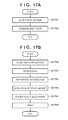
- FIGS. 17A and 17B are flowcharts for explaining a printing sequence of PDL data on an envelope by a print job according to the embodiment
- FIG. 18 is a flowchart for explaining offset amount acquisition processing in step S 1713 of FIG. 17B ;
- FIG. 19 is a flowchart for explaining processing in step S 1805 of FIG. 18 ;
- FIGS. 20A to 20C are views for explaining an envelope of end-opening envelope (long format) 3 , and examples of printing an image on the envelope;
- FIG. 21 is a view showing an image of image data rasterized in a memory when end-opening envelope (long format) 3 is set as the image size;
- FIG. 22 is a view exemplifying a UI screen displayed on the display unit of the operation unit when a flap size is abnormal.
- FIG. 1 is a view showing the arrangement of a multi-function peripheral (MFP) serving as an example of a printing apparatus according to an embodiment of the present invention.
- MFP multi-function peripheral
- SFP single-function peripheral
- a controller 101 controls the MFP, and has a hardware arrangement shown in FIG. 2 .
- a scanner 102 is controlled by the controller 101 , and scans a document to create image data of the document image.
- a printer engine 103 is a printer engine complying with the electrophotographic method in the embodiment. The printer engine 103 prints an image on a printing medium (sheet such as paper or envelope) under the control of the controller 101 .
- a finisher 104 is connectable to the printer engine 103 , and can perform, for example, staple processing collectively for a plurality of printing media (for example, sheets) output from the printer engine 103 .
- the controller 101 also controls the finisher 104 .
- a network (Ethernet) interface 105 provides two-way communication with the controller 101 via itself, and can connect the MFP to a PC 107 serving as an external apparatus via a network.
- An operation unit 106 provides a user interface, includes a display unit and keyboard, displays information from the controller 101 , and notifies the controller 101 of an instruction from the user.
- FIG. 2 is a block diagram showing the hardware arrangement of the controller 101 according to the embodiment.
- a CPU 201 is connected to a memory 202 , a display unit 203 and keyboard 204 of the operation unit 106 , a ROM 210 , and a storage medium (DISK) 211 via a bus 209 .
- Various programs and data are stored in the DISK 211 such as a hard disk or Floppy® disk, and if necessary, sequentially read out to the memory 202 and executed by the CPU 201 .
- the DISK 211 may be one detachable from the MFP or one incorporated in the MFP. Further, programs may be downloaded from another PC, MFP, or the like via the network and stored in the DISK 211 .
- the memory 202 may have both the functions of volatile and nonvolatile memories. Alternatively, the memory 202 may have the function of a volatile memory, and the DISK 211 may have the function of a nonvolatile memory. The memory 202 may be a removable memory medium.
- the CPU 201 writes display data in a display memory (not shown) to present a display on the display unit 203 .
- the CPU 201 receives data from the keyboard 204 or the display unit 203 serving as a touch panel, thereby accepting input of an instruction from the user.
- the input information is transferred to one of the memory 202 , DISK 211 , and CPU 201 , accumulated, and used for various processes.
- the network interface 105 is connected to the bus 209 , and the CPU 201 performs communication via the interface by loading or writing data via the network interface 105 .
- the printer engine 103 , finisher 104 , and scanner 102 are connected to the bus 209 .
- the CPU 201 reads and writes data from and in the printer engine 103 , finisher 104 , and scanner 102 to execute operations such as printing and scanning, and acquire information representing various statuses.
- Image data can be saved in the DISK 211 or memory 202 of the controller 101 from the scanner 102 or network interface 105 . Also, image data can be accumulated in advance in a removable memory and loaded by attaching the memory to the controller 101 . Image data accumulated in the DISK 211 can be moved or copied to the memory 202 .
- Various additional images can be composited with image data in the memory 202 in accordance with contents designated from the operation unit 106 .
- the printer engine 103 , finisher 104 , and scanner 102 may exist not in the MFP but as single peripheral devices on the network, and may be controlled by the controller 101 of the MFP.
- FIG. 3 is a schematic view showing the MFP according to the embodiment. Note that the same reference numerals as those in FIG. 1 denote the same parts.
- the scanner 102 serving as an image input device irradiates an image on a sheet serving as a document with light, and scans a CCD line sensor to convert the document image into electrical image data.
- the scanner 102 determines the color and size of the document from the electrically converted image data.
- a printer unit 302 serving as an image output device converts image data into an image on a sheet, prints the image on a sheet, and discharges the sheet. The print operation starts and stops in accordance with instructions from the CPU 201 of the controller 101 .
- Reference numerals 304 to 308 denote paper feed sources.
- the paper feed source 304 is a manual feed tray, and the paper feed sources 305 to 308 are paper feed cassettes (paper containing units or sheet holding units), in each of which a plurality of sheets (including envelopes) can be set. Note that the MFP can print, based on print data, an image on an envelope held in the manual feed tray 304 or the paper feed cassette.
- FIG. 4 is a plan view showing the operation unit 106 of the MFP according to the embodiment.
- the display unit 203 is formed from a touch panel sheet adhering to a liquid crystal display, and displays an operation screen and soft keys. When the user presses a displayed key, the display unit 203 notifies the CPU 201 of the position information.
- a start key 402 is used to designate the start of a document image reading operation.
- An LED 403 in two, green and red colors is arranged at the center of the start key 402 , and the colors represent whether the start key 402 is available.
- a stop key 404 is used to stop an operation in progress.
- a ten-key pad 405 is formed from numeric and character buttons, and used to set a copy count and designate screen switching of the display unit 203 and the like.
- a user mode key 406 is pressed to make settings of the MFP.
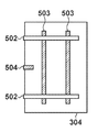
- FIGS. 5A to 5C are views showing the manual feed tray 304 when viewed from above.
- the manual feed tray 304 includes guides 502 which are freely movable on rails 503 .
- the positions of the guides 502 can be adjusted in accordance with the size of paper to be set.
- FIG. 5B shows guide positions when A4-size paper is set in the portrait direction. This represents a conveyance direction in long-edge feed described above.
- FIG. 5C shows guide positions when A4-size paper is set in the landscape direction. This represents a conveyance direction in short-edge feed described above.
- a sensor 504 detects that paper is placed on the manual feed tray 304 . When paper is placed on the sensor 504 , the controller 101 can detect, based on an output from the sensor 504 , that paper is set on the manual feed tray 304 .
- FIG. 5D shows the arrangement of the manual feed tray 304 when viewed from below.
- Members 508 are fixed to the guides 502 via the rails 503 .
- Members 509 are fixed to the members 508 and move in synchronism with movement of the guides 502 and members 508 .
- a rotation member 510 forms a rack and pinion structure with the members 509 , and rotates along with movement of the members 509 .
- the rotation member 510 includes a rotation angle sensor which can measure rotation of the rotation member 510 . By measuring the rotation amount of the rotation member 510 , the opening width between the guides 502 can be measured.
- FIGS. 6A to 8B are views each exemplifying a UI screen displayed on the display unit 203 of the operation unit 106 of the MFP according to the embodiment.
- a method of setting the size and type of paper in a paper feed cassette from a user mode screen in FIG. 6A will be explained with reference to FIGS. 6A to 8B .
- a user mode screen in FIG. 6A appears.
- the user can set a paper size on this operation screen.
- a paper setting button 602 in a button group 601 a screen shown in FIG. 6B for setting the size and type of paper to be set in the paper feed cassette appears.
- the screen in FIG. 6B provides a cassette selection button group 604 .
- the user can select an arbitrary paper feed cassette.
- a screen shown in FIG. 7A appears.
- the screen in FIG. 7A provides a standard-size setting button group 608 .
- the user can set an arbitrary standard-size for the paper feed cassette selected in FIG. 6B .
- the user presses a user setting button 609 to set paper of an arbitrary size.
- a screen shown in FIG. 7B appears.
- the screen in FIG. 8A provides an envelope size setting button group 620 .
- the user can set the standard-size of an envelope.
- a button corresponding to “end-opening envelope (long format) 3 ” is selected as a default.
- the default changes depending on the destination (“destination” is information indicating a country or region where a device is installed, and is saved in either the memory 202 or DISK 211 of the controller 101 ).
- the default is “end-opening envelope (long format) 3 ” for Japan and “Com10” for overseas.
- the screen in FIG. 8A returns to one in FIG. 7A without any setting.
- an envelope size is set, and the screen in FIG. 8A returns to one in FIG. 7A .
- FIG. 8B When the user sets a standard-size or user-set size as the envelope size and then presses a “Next” button 612 in FIG. 7A , a screen in FIG. 8B appears.
- This screen provides a paper type setting button group 624 .
- the user can set a paper type.
- the user presses a cancel button 625 to cancel settings on the screen.
- the screen in FIG. 8B returns to one in FIG. 7A without any setting.
- the user presses an OK button 626 to decide a paper type.
- the OK button 626 a paper type is set, and the screen in FIG. 8B returns to one in FIG. 6B .
- Table 1 below exemplifies information set for each paper feed cassette according to the embodiment. After the end of paper setting processing, data for one of cassette 1 to cassette 4 in Table 1 is updated. The data can be saved in either the memory 202 or DISK 211 of the controller 101 .
- the user can set a paper type by pressing a button in the paper type setting button group 624 , or return the screen in FIG. 8B to one in FIG. 7A by pressing the cancel button 625 .
- the paper registration screen disappears, and the size and paper type in “Manual Feed” of Table 1 are updated from “unset” to an actually set size and type.
- the sensor 504 detects this, and the printer engine 103 notifies the controller 101 that sheets have run out. Upon receiving this notification, the controller 101 updates each item in “Manual Feed” of Table 1 to “unset”.
- FIG. 9 is a view for explaining the structure of the scanner 102 .
- Information on a document 703 is read while the document 703 is moved relative to an exposure unit 713 of a document reading device 719 .
- the document 703 is set on a document tray 702 .
- a document feed roller 704 is paired with a separation pad 705 , and conveys the documents 703 one by one.
- the conveyed document 703 is sent into the scanner by intermediate rollers 706 , conveyed by a large roller 708 and first driven roller 709 , and further conveyed by the large roller 708 and a second driven roller 710 .
- the document 703 conveyed by the large roller 708 and second driven roller 710 passes between a sheet-fed document glass 712 and a document guide plate 717 , and conveyed by the large roller 708 and a third driven roller 711 via a jump table 718 .
- the document 703 conveyed by the large roller 708 and third driven roller 711 is discharged by a pair of document discharge rollers 707 . Note that the document 703 is conveyed between the sheet-fed document glass 712 and the document guide plate 717 to contact the sheet-fed document glass 712 by the document guide plate 717 .
- the exposure unit 713 exposes a surface of the document 703 that contacts the sheet-fed document glass 712 .
- the light reflected by the document 703 travels to a mirror unit 714 .
- the traveling reflected light is condensed through a lens 715 , and converted into an electrical signal by a CCD sensor 716 .
- the electrical signal is transferred to the controller 101 .
- FIG. 10 is a view for explaining the arrangement of the printer unit 302 .
- FIG. 10 exemplifies a full-color printing apparatus.
- a primary charger 811 charges a photosensitive drum 801 to a potential of a specific polarity, and an exposure unit (not shown) exposes a position indicated by an arrow 812 in accordance with an instruction from the controller 101 .
- an electrostatic latent image corresponding to the first color component is formed.
- the electrostatic latent image is developed using one of four developing units of a developing device 802 .
- An intermediate transfer belt 803 is driven to be conveyed in a direction indicated by an arrow.
- the image of the first color component formed on the photosensitive drum 801 passes through a contact portion between the photosensitive drum 801 and the intermediate transfer belt 803 , it is transferred onto the intermediate transfer belt 803 by an electric field formed by a primary transfer roller 810 .
- a cleaning device 804 cleans the surface of the photosensitive drum 801 after the end of transfer onto the intermediate transfer belt 803 .
- This processing is sequentially repeated to transfer images of four colors onto the intermediate transfer belt 803 and superimpose them on each other, thereby forming a color image.
- transfer processing is performed only once.
- the image transferred onto the intermediate transfer belt 803 is printed onto paper fed from a paper feed cassette 805 by a secondary transfer roller 809 .
- a fixing unit 806 heats the paper and fixes the image printed on it.
- the paper after fixing passes through conveyance rollers, is discharged outside the apparatus from a discharge port 807 , and stacked on a discharge tray 813 .
- paper is circulated through a reverse path 808 and print processing is repeated.
- FIG. 11 is a view exemplifying a UI screen for selecting a paper feed cassette subjected to auto paper selection.
- Auto paper selection is processing of automatically selecting a paper feed source serving as the source of paper to be used in printing from a plurality of paper feed sources by the CPU 201 in accordance with the document size and user settings.
- the user mode screen in FIG. 6A appears.
- the screen shown in FIG. 11 appears.
- This screen displays equipped paper feed cassettes and the size of paper set in each paper feed cassette.
- a selection button group 902 the user can designate whether or not to set the paper feed cassette as a cassette to be selected automatically.
- a cassette source for which “ON” is pressed becomes a cassette subjected to auto paper selection.
- a cassette for which “OFF” is pressed becomes a cassette not subjected to auto paper selection.
- OK button 903 setting ends, and the screen in FIG. 11 returns to one in FIG. 6A .
- Table 2 below exemplifies data representing auto paper selection of paper feed cassettes and a manual feed tray according to the embodiment.
- data for one of cassette 1 to cassette 4 and the manual feed tray in Table 2 is updated in correspondence with the setting.
- the data can be saved in either the memory 202 or DISK 211 of the controller 101 .
- This data is used when automatically selecting a cassette. In the example of Table 2, it is set to use all cassettes 1 to 4 in auto paper switching and not to use only the manual feed tray in auto paper switching.
- FIG. 12 is a view for explaining the data structure of a print job in the embodiment. This data is generated by an application in the device upon receiving an instruction to execute a print job.
- the entity of the job is represented by successively arranging a plurality of sets each of an attribute ID 1101 , attribute value size 1102 , and attribute value 1103 .
- a job When a job contains data, it holds a value representing data as an attribute ID, the size of a file name as an attribute value size, and the file name of a file holding document data as an attribute value, as represented by 1107 , 1108 , and 1109 .
- Each attribute value contains a data format (for example, PDL used), copy count, cassette source, paper size used in printing, and designation of finishing processing.
- FIG. 13 is a table exemplifying attributes according to the embodiment.
- An attribute ID 1301 represents the identification number (ID) of an attribute.
- a type ID 1302 represents the type (size) of an ID, which is set in advance such that “1” is an undefined length and “2” is 1 byte.
- a value 1303 represents a possible value and has a meaning as represented by a meaning 1304 .
- the attributes shown in FIG. 13 are merely examples, and there are various other attributes.
- a job is formed by setting these values in the attribute ID, attribute size, and attribute value of a job shown in FIG. 12 .
- FIG. 14 is a flowchart showing an operation of automatically switching a cassette source in the MFP according to the embodiment when sheets run out during printing by a print job for which a paper size is designated. Note that a program for executing this processing is stored in the ROM 210 or DISK 211 , loaded in the memory 202 in execution, and executed under the control of the CPU 201 .
- the CPU 201 acquires a paper size requested of processing from an attribute designated by the job in step S 1401 .
- the process advances to step S 1402 , and the CPU 201 searches for a cassette whose state is set to ON in Table 2.
- the process then advances to step S 1403 , and the CPU 201 compares the paper size acquired in step S 1401 with the paper sizes of respective cassettes whose states are ON in step S 1402 , and determines whether there is a cassette matching the paper size. For example, when the paper size acquired in step S 1401 is B4, it is detected that B4-size sheets are set in cassette 4 out of target cassettes 1 to 4 (see Table 1). If all cassette auto ON/OFF settings are “OFF” in Table 2 or a cassette containing B4-size sheets does not exist in Table 1, there is no matching cassette.
- step S 1404 the CPU 201 determines whether there is a matching cassette. If there is a matching cassette, the process advances to step S 1405 , and the CPU 201 restarts the job by using the cassette source matching the size. If the CPU 201 determines in step S 1404 that there is no matching cassette, the process advances to step S 1406 , and the CPU 201 notifies the user that there is no usable size, and keeps interrupting the job.
- FIGS. 15A, 15B, and 16 An envelope size setting method according to the embodiment will be explained with reference to FIGS. 15A, 15B, and 16 .
- the operation unit 106 displays the screen in FIG. 7A .
- a screen in FIG. 15A appears.
- the screen provides an envelope size setting button group 1402 .
- the user can set an envelope size.
- end-opening envelope (long format) 3 is selected as a default.
- the screen changes to a setting screen shown in FIG. 15B for longitudinal feed in which an envelope is printed with its short edge set parallel to the main-scanning direction.
- FIGS. 15A and 15B the screen changes to a lateral feed setting screen shown in FIG. 15A .
- the screens in FIGS. 15A and 15B include the envelope size setting button group 1402 and an envelope size setting button group 1407 , respectively.
- the user can set an envelope size.
- the user presses a cancel button 1404 or 1409 to cancel settings on the screen.
- the cancel button 1404 or 1409 the setting screen returns to the screen in FIG. 7A without any setting on the setting screen.
- This screen includes a numeric value input area 1413 for setting a flap size.
- a numeric key group 1412 By using a numeric key group 1412 , the user can enter a flap size setting value to the numeric value input area 1413 .
- a flap size which has been set for the selected envelope size is acquired from a memory having the data structure shown in Table 3, and displayed. Hence, a flap size which has been set previously in association with the envelope size is displayed.
- the cancel button 1414 returns to one in FIG. 15B .
- An auto button 1416 is arranged on the flap size setting screen of FIG. 16 .
- “auto” is displayed in the numeric value input area 1413 , and the auto button 1416 is highlighted. This means that a flap size is acquired automatically.
- the highlight of the auto button 1416 is canceled, and an entered numeric value is displayed in the numeric value input area 1413 .
- Table 3 shows a data structure used in processing according to the embodiment. After the end of envelope setting processing, data of either the flap size or auto flag in Table 3 is updated. The data can be saved in either the memory 202 or DISK 211 of the controller 101 . Assume that “reference size” in Table 3 is set in advance in association with an envelope size.
- FIGS. 17A and 17B are flowcharts for explaining a printing sequence of PDL data on an envelope by a print job according to the embodiment.
- FIG. 17A shows processing by the PC 107
- FIG. 17B shows processing by the MFP according to the embodiment.
- the processing shown in the flowchart of FIG. 17A is implemented by reading out a program stored in the ROM (not shown) of the PC 107 and executing it by the CPU (not shown) of the PC 107 .
- the processing shown in the flowchart of FIG. 17B is implemented by reading out a program stored in the ROM 210 and executing it by the CPU 201 .
- step S 1701 of FIG. 17A the PC 107 accepts the print settings of a PDL image output job from the user.
- the print setting contents include the copy count, paper size (envelope size in printing on an envelope), single-sided/double-sided, page output order, sort output, and stapling/no-stapling.
- the process advances to step S 1702 , and the PC 107 accepts a print instruction from the user, and converts code data to be printed into so-called PDL data (print data) by using driver software installed in the PC 107 .
- the PC 107 transfers the PDL data to the controller 101 via the network interface 105 together with the print setting parameters set in step S 1701 .
- step S 1710 the CPU 201 detects that, for example, an envelope of end-opening envelope (long format) 3 in FIG. 20A is set on the manual feed tray 304 .
- the user selects the “longitudinal feed” 1403 in FIG. 15A , and sets “end-opening envelope (long format) 3 ” as the envelope size in FIG. 15B .
- the items of “Manual Feed” in Table 1 are updated as shown on the upper side of Table 4.
- step S 1711 the CPU 201 receives the PDL data transferred from the PC 107 via the network interface 105 .
- the process advances to step S 1712 , and the CPU 201 rasterizes the PDL data into image data based on the print setting parameters. Rasterization into image data is executed in the memory 202 .
- FIG. 21 is a view showing an image of image data rasterized in the memory when end-opening envelope (long format) 3 is set as the image size.
- End-opening envelope (long format) 3 is defined by a size of 120 mm ⁇ 235 mm. Image data of a size corresponding to this size is rasterized in the memory 202 .
- step S 1713 the CPU 201 acquires an offset amount based on the paper size (envelope size) designated by the PDL job.
- the offset amount acquisition processing will be described in detail with reference to the flowchart of FIG. 18 .
- step S 1714 the CPU 201 selects a paper feed source matching the acquired paper size. Since the designated paper size is end-opening envelope (long format) 3 , the CPU 201 selects a paper feed source (manual feed tray in this case) in which an envelope of end-opening envelope (long format) 3 is set, and acquires a paper feed direction set for the paper feed source.
- step S 1715 the CPU 201 controls the printer engine 103 to perform printing control based on image data.
- the image is printed by shifting the image data output position by the offset amount in the sub-scanning direction. Accordingly, a printing result as shown in FIG. 20B can be acquired. If the image data output position is not shifted by the offset amount, the printing result becomes one as shown in FIG. 20C in which the positions of the address and postal code shift from correct positions. This is because, if an image rasterized in the memory 202 is printed on an envelope with its upper end aligned with the upper end of the envelope, similar to printing an image on paper other than an envelope, the image is not printed at a correct position owing to the presence of the flap of the envelope.
- FIG. 18 is a flowchart for explaining offset amount acquisition processing in step S 1713 of FIG. 17B .
- This processing is implemented by reading out a program stored in the ROM 210 and executing it by the CPU 201 .
- step S 1801 the CPU 201 acquires a paper size designated by the PDL job from attributes.
- the process advances to step S 1802 , and the CPU 201 determines whether the acquired paper size coincides an envelope size managed in Table 3. If no coincident size exists in Table 3 in step S 1802 , the process advances to step S 1803 , the CPU 201 determines that no offset amount is set, and the process returns to the processing in FIG. 17B . If a coincident size exists in Table 3 in step S 1802 , the process advances to step S 1804 , and the CPU 201 determines whether it is set to automatically acquire a flap size, that is, the auto flag is “Yes”.
- step S 1805 the CPU 201 calculates a flap size based on the reference size in Table 3 and the opening width between the guides 502 ( FIG. 5D ).
- FIG. 19 is a flowchart for explaining processing in step S 1805 of FIG. 18 .
- step S 1901 by looking up Table 3, the CPU 201 acquires a reference size corresponding to the paper size (envelope size) acquired in step S 1801 .
- a reference size corresponding to the paper size (envelope size) acquired in step S 1801 .
- the envelope size is end-opening envelope (long format) 3
- “235 mm” is acquired as the reference size.
- the process advances to step S 1902 , and the CPU 201 acquires the opening width between the guides 502 . More specifically, the opening width between the guides 502 is acquired from the output value of the rotation angle sensor of the rotation member 510 . At this time, the opening width between the guides 502 can be acquired by looking up, for example, a table describing the relationship between the output value of the rotation angle sensor and the opening width between the guides 502 .
- step S 1903 the CPU 201 calculates a flap size. More specifically, the CPU 201 sets, as the flap size, a difference calculated by subtracting the reference size acquired in step S 1901 from the opening width between the guides 502 that has been acquired in step S 1902 .
- step S 1904 the CPU 201 determines whether the flap size calculated in step S 1903 is a value within a normal range.
- the opening width acquired in step S 1902 may not indicate a normal value.
- the CPU 201 determines that the flap size is not a normal value. If the CPU 201 determines that the flap size is a normal value, it advances the process to step S 1905 ; if NO, to step S 1906 .
- step S 1905 the CPU 201 updates the data shown in Table 3 by using the flap size calculated in step S 1903 .
- the flap size calculated in step S 1903 is 30 mm
- the items of end-opening envelope (long format) 3 in Table 3 are updated as shown in Table 5.
- step S 1906 the CPU 201 discards the flap size calculated in step S 1903 .
- step S 1906 the CPU 201 sets the flap size in Table 3 to be 0 mm, in order to ensure consistency with steps S 1807 to S 1811 of FIG. 18 (to be described later).
- the CPU 201 ends the flap size calculation processing in step S 1805 , and advances the process to step S 1806 of FIG. 18 . In this manner, the CPU 201 identifies the flap size of the envelope (set on the manual feed tray 304 ).
- step S 1806 the CPU 201 acquires a flap size.
- the flap size acquired here is a flap size manually entered by the user via the screen of FIG. 16 , or a flap size calculated by the CPU 201 in step S 1805 .
- the flap size serves as an offset amount candidate.
- the flap size is 0 mm and the offset amount candidate becomes 0 mm.
- the CPU 201 may determine that this flap size is abnormal, and interrupt the job. This processing is implemented by performing processes in steps S 1809 to S 1811 . If the job is not interrupted, the CPU 201 performs processing in step S 1808 .
- step S 1807 the CPU 201 determines whether the flap size is equal to or smaller than the threshold. If the flap size is equal to or smaller than the threshold, the process advances to step S 1809 , and the CPU 201 interrupts the job and displays a screen shown in FIG. 22 on the display unit 203 of the operation unit 106 .
- FIG. 22 is a view exemplifying a UI screen displayed on the display unit 203 of the operation unit 106 when a flap size is abnormal.
- step S 1809 the CPU 201 displays the screen shown in FIG. 22 on the display unit 203 , notifies the user that the flap size is abnormal, and prompts him to select whether to continue the job or set again the flap size. If the user wants to continue the processing, the current flap size is displayed in a flap size display area 2202 , and the user enters a normal value by using a ten-key pad 2201 . When the user presses an OK button 2204 after entering the flap size, the CPU 201 sets the entered value as the flap size, and updates (sets again) the flap size in Table 3 (step S 1811 ). If the user wants to stop the job, he presses a stop button 2203 , and the CPU 201 ends the job (“NO” in step S 1810 ).
- step S 1807 determines in step S 1807 that the flap size is larger than the threshold
- the process advances to step S 1808 , and the CPU 201 sets the flap size acquired in step S 1806 as the offset amount.
- step S 1802 determines in step S 1802 that no coincident size exists, the process advances to step S 1803 , and the CPU 201 sets the offset amount to be 0 mm, continues the processing, and returns to the processing in FIG. 17B .
- a flap size corresponding to a standard envelope size can be automatically acquired. Even if, for example, a job for image data of a size not containing a flap size is input as a PDL job from a PC or the like, an image can be printed at an appropriate position on an envelope in consideration of the flap.
- a flap size is automatically calculated in printing.
- a flap size may be calculated when paper is set. More specifically, when the user presses the auto button 1416 in FIG. 16 , the calculation processing in FIG. 19 may be executed. In this case, the processes in steps S 1804 and S 1805 of FIG. 18 become unnecessary.
- the flap size in Table 3 has already been set, and the processing can proceed similarly to a case in which a flap size is set manually.
- aspects of the present invention can also be realized by a computer of a system or apparatus (or devices such as a CPU or MPU) that reads out and executes a program recorded on a memory device to perform the functions of the above-described embodiment(s), and by a method, the steps of which are performed by a computer of a system or apparatus by, for example, reading out and executing a program recorded on a memory device to perform the functions of the above-described embodiment(s).
- the program is provided to the computer for example via a network or from a recording medium of various types serving as the memory device (for example, computer-readable medium).
Abstract
A printing apparatus according to one aspect of this invention includes a sheet holding unit configured to hold an envelope, and a detection unit configured to detect an opening width between guides for guiding an envelope held by the sheet holding unit. The printing apparatus further includes an identifying unit configured to identify a flap size of the envelope based on the opening width detected by the detection unit and a size set for the envelope held by the sheet holding unit, and a printing unit configured to print an image on the envelope by shifting image data based on the flap size identified by the identifying unit.
Description
This application is a continuation of U.S. application Ser. No. 13/755,960, filed Jan. 31, 2013, the contents of which are incorporated herein by reference.
1. Field of the Invention
The present invention relates to a printing apparatus capable of printing an image on paper such as an envelope, a control method therefor, and a storage medium.
2. Description of the Related Art
An image forming apparatus (printing apparatus) includes one or more paper containing units (sheet holding unit). The image forming apparatus feeds sheets contained in the paper containing unit one by one, and forms (prints) an image on the fed sheet. The size of paper contained in each paper containing unit can be set. For example, standard-sizes such as A4 and B4, and an arbitrary size such as 210 mm×290 mm can be set.
As a special standard-size, an envelope size can also be set. Paper with a projection such as the projecting piece, that is, margin (to be referred to as a flap hereinafter) of an envelope or the index portion of index paper is set so that the flap serves as the trailing end in the sub-scanning direction. With this setting, a paper area up to the flap is handled as a standard-size, and printing is performed. Also, there is known a technique of setting an envelope so that its flap is positioned in the sub-scanning direction, recognizing a flap position by a sensor when the envelope is conveyed, and suppressing image misregistration (see Japanese Patent Laid-Open No. 9-109492).
Paper longer in the sub-scanning direction than in the main-scanning direction, like an envelope, takes a long printing time when the long edge is made parallel to the conveyance direction and printing is performed (short-edge feed). The time necessary to print can be shortened by setting an envelope so that its flap comes to the end in the main-scanning direction, making the short edge of the envelope parallel to the conveyance direction, and printing (long-edge feed). In this case, an image needs to be shifted by the flap width and printed. However, since the flap width differs between envelope manufacturers, the user needs to enter a flap width, putting a burden on him.
The present invention solves the conventional problems.
The present invention provides a technique of identifying a flap size necessary to appropriately print an image on an envelope while suppressing the burden on the user.
According to one aspect of the present invention, there is provided a printing apparatus comprising: a sheet holding unit configured to hold an envelope; a detection unit configured to detect an opening width between guides for guiding an envelope held by the sheet holding unit; an identifying unit configured to identify a flap size of the envelope based on the opening width detected by the detection unit and a size set for the envelope held by the sheet holding unit; and a printing unit configured to print an image on the envelope by shifting image data based on the flap size identified by the identifying unit.
According to another aspect of the present invention, there is provided a method for controlling a printing apparatus including a sheet holding unit configured to hold an envelope, comprising: detecting an opening width between guides for guiding an envelope held by the sheet holding unit; identifying a flap size of the envelope based on the opening width detected in the detecting an opening width, and a size set for the envelope held by the sheet holding unit; and printing an image on the envelope by shifting image data based on the flap size identified in the identifying a flap size.
According to the present invention, a flap size necessary to appropriately print an image on an envelope can be identified while suppressing the burden on the user.
Further features of the present invention will become apparent from the following description of exemplary embodiments (with reference to the attached drawings).
Hereinafter, embodiments of the present invention will be described in detail with reference to the accompanying drawings. It should be noted that the following embodiments are not intended to limit the scope of the appended claims, and that not all the combinations of features described in the embodiments are necessarily essential to the solving means of the present invention.
Referring to FIG. 1 , a controller 101 controls the MFP, and has a hardware arrangement shown in FIG. 2 . A scanner 102 is controlled by the controller 101, and scans a document to create image data of the document image. A printer engine 103 is a printer engine complying with the electrophotographic method in the embodiment. The printer engine 103 prints an image on a printing medium (sheet such as paper or envelope) under the control of the controller 101. A finisher 104 is connectable to the printer engine 103, and can perform, for example, staple processing collectively for a plurality of printing media (for example, sheets) output from the printer engine 103. The controller 101 also controls the finisher 104. A network (Ethernet) interface 105 provides two-way communication with the controller 101 via itself, and can connect the MFP to a PC 107 serving as an external apparatus via a network. An operation unit 106 provides a user interface, includes a display unit and keyboard, displays information from the controller 101, and notifies the controller 101 of an instruction from the user.
In the controller 101, a CPU 201 is connected to a memory 202, a display unit 203 and keyboard 204 of the operation unit 106, a ROM 210, and a storage medium (DISK) 211 via a bus 209. Various programs and data are stored in the DISK 211 such as a hard disk or Floppy® disk, and if necessary, sequentially read out to the memory 202 and executed by the CPU 201. The DISK 211 may be one detachable from the MFP or one incorporated in the MFP. Further, programs may be downloaded from another PC, MFP, or the like via the network and stored in the DISK 211.
The memory 202 may have both the functions of volatile and nonvolatile memories. Alternatively, the memory 202 may have the function of a volatile memory, and the DISK 211 may have the function of a nonvolatile memory. The memory 202 may be a removable memory medium.
The CPU 201 writes display data in a display memory (not shown) to present a display on the display unit 203. The CPU 201 receives data from the keyboard 204 or the display unit 203 serving as a touch panel, thereby accepting input of an instruction from the user. The input information is transferred to one of the memory 202, DISK 211, and CPU 201, accumulated, and used for various processes. The network interface 105 is connected to the bus 209, and the CPU 201 performs communication via the interface by loading or writing data via the network interface 105.
Further, the printer engine 103, finisher 104, and scanner 102 are connected to the bus 209. The CPU 201 reads and writes data from and in the printer engine 103, finisher 104, and scanner 102 to execute operations such as printing and scanning, and acquire information representing various statuses. Image data can be saved in the DISK 211 or memory 202 of the controller 101 from the scanner 102 or network interface 105. Also, image data can be accumulated in advance in a removable memory and loaded by attaching the memory to the controller 101. Image data accumulated in the DISK 211 can be moved or copied to the memory 202. Various additional images (for example, a page number) can be composited with image data in the memory 202 in accordance with contents designated from the operation unit 106. Note that the printer engine 103, finisher 104, and scanner 102 may exist not in the MFP but as single peripheral devices on the network, and may be controlled by the controller 101 of the MFP.
The scanner 102 serving as an image input device irradiates an image on a sheet serving as a document with light, and scans a CCD line sensor to convert the document image into electrical image data. The scanner 102 determines the color and size of the document from the electrically converted image data. A printer unit 302 (printer engine 103) serving as an image output device converts image data into an image on a sheet, prints the image on a sheet, and discharges the sheet. The print operation starts and stops in accordance with instructions from the CPU 201 of the controller 101. Reference numerals 304 to 308 denote paper feed sources. The paper feed source 304 is a manual feed tray, and the paper feed sources 305 to 308 are paper feed cassettes (paper containing units or sheet holding units), in each of which a plurality of sheets (including envelopes) can be set. Note that the MFP can print, based on print data, an image on an envelope held in the manual feed tray 304 or the paper feed cassette.
The display unit 203 is formed from a touch panel sheet adhering to a liquid crystal display, and displays an operation screen and soft keys. When the user presses a displayed key, the display unit 203 notifies the CPU 201 of the position information.
Next, the keyboard 204 will be explained. A start key 402 is used to designate the start of a document image reading operation. An LED 403 in two, green and red colors is arranged at the center of the start key 402, and the colors represent whether the start key 402 is available. A stop key 404 is used to stop an operation in progress. A ten-key pad 405 is formed from numeric and character buttons, and used to set a copy count and designate screen switching of the display unit 203 and the like. A user mode key 406 is pressed to make settings of the MFP.
In FIG. 5A , the manual feed tray 304 includes guides 502 which are freely movable on rails 503. The positions of the guides 502 can be adjusted in accordance with the size of paper to be set. FIG. 5B shows guide positions when A4-size paper is set in the portrait direction. This represents a conveyance direction in long-edge feed described above. FIG. 5C shows guide positions when A4-size paper is set in the landscape direction. This represents a conveyance direction in short-edge feed described above. A sensor 504 detects that paper is placed on the manual feed tray 304. When paper is placed on the sensor 504, the controller 101 can detect, based on an output from the sensor 504, that paper is set on the manual feed tray 304.
When the user presses the user mode key 406 (FIG. 4 ) of the operation unit 106, a user mode screen in FIG. 6A appears. The user can set a paper size on this operation screen. When the user presses a paper setting button 602 in a button group 601, a screen shown in FIG. 6B for setting the size and type of paper to be set in the paper feed cassette appears.
The screen in FIG. 6B provides a cassette selection button group 604. By pressing a button in the button group 604, the user can select an arbitrary paper feed cassette. When the user selects a paper feed cassette from the button group 604 and presses a set button 605, a screen shown in FIG. 7A appears.
The screen in FIG. 7A provides a standard-size setting button group 608. By pressing a button in the button group 608, the user can set an arbitrary standard-size for the paper feed cassette selected in FIG. 6B . The user presses a user setting button 609 to set paper of an arbitrary size. When the user presses the user setting button 609, a screen shown in FIG. 7B appears.
The user presses an X button 614 in FIG. 7B to set a width (dimension in the lateral direction). With a numeric button group 616, the user sets the width value. The user presses a Y button 615 to set a length (dimension in the longitudinal direction). With the numeric button group 616, the user sets the length value. The user presses a cancel button 617 to cancel settings on the screen. When the user presses the cancel button 617, the screen in FIG. 7B returns to one in FIG. 7A without any setting. The user presses an OK button 618 to end input of dimensions in the longitudinal and lateral directions, and set these values. When the user presses the OK button 618, the screen in FIG. 7B returns to one in FIG. 7A .
The user presses an envelope button 610 in FIG. 7A to set an envelope size. When the user presses the envelope button 610, a screen in FIG. 8A appears. The screen in FIG. 8A provides an envelope size setting button group 620. By pressing a button in the button group 620, the user can set the standard-size of an envelope. A button corresponding to “end-opening envelope (long format) 3” is selected as a default. The default changes depending on the destination (“destination” is information indicating a country or region where a device is installed, and is saved in either the memory 202 or DISK 211 of the controller 101). The default is “end-opening envelope (long format) 3” for Japan and “Com10” for overseas. The user presses a cancel button 621 to cancel settings on the screen. When the user presses the cancel button 621, the screen in FIG. 8A returns to one in FIG. 7A without any setting. The user presses an OK button 622 to decide an envelope size. When the user presses the OK button 622, an envelope size is set, and the screen in FIG. 8A returns to one in FIG. 7A .
When the user sets a standard-size or user-set size as the envelope size and then presses a “Next” button 612 in FIG. 7A , a screen in FIG. 8B appears. This screen provides a paper type setting button group 624. By pressing a button in the button group 624, the user can set a paper type. The user presses a cancel button 625 to cancel settings on the screen. When the user presses the cancel button 625, the screen in FIG. 8B returns to one in FIG. 7A without any setting. The user presses an OK button 626 to decide a paper type. When the user presses the OK button 626, a paper type is set, and the screen in FIG. 8B returns to one in FIG. 6B . Further, when the user wants to set another paper feed source, he selects a paper feed cassette again from the cassette selection button group 604, and repeats setting processing. If no setting is made, the user presses a close button 606, and then the screen returns to one in FIG. 6A .
Table 1 below exemplifies information set for each paper feed cassette according to the embodiment. After the end of paper setting processing, data for one of cassette 1 to cassette 4 in Table 1 is updated. The data can be saved in either the memory 202 or DISK 211 of the controller 101.
| TABLE 1 | ||||
| Cassette | ||||
| Source | Paper Size | X Size | Y Size | |
| Cassette | ||||
| 1 | A4 | — | — | |
| Cassette | ||||
| 2 | End-opening | — | — | Thick paper |
| envelope | ||||
| (long format) 3 | ||||
| |
User setting | 200 mm | 297 mm | |
| Cassette | ||||
| 4 | B4 | — | — | Plain paper |
| Manual Feed | Unset | — | — | Unset |
Next, a method of setting the size and type of paper when paper is set on the manual feed tray 304 will be explained. When the user sets paper on the manual feed tray 304 and sets a state as shown in FIG. 5B or 5C , the sensor 504 detects this and the printer engine 103 notifies the controller 101 that paper has been set. Upon receiving this notification, the controller 101 displays the screen shown in FIG. 7A on the display unit 203 of the operation unit 106. In this case, a Back button 611 is hidden. As described above, when the user sets a standard-size or user-set size as the envelope size on this screen and then presses the “Next” button 612, the screen in FIG. 8B appears. As described above, this screen provides the paper type setting button group 624. The user can set a paper type by pressing a button in the paper type setting button group 624, or return the screen in FIG. 8B to one in FIG. 7A by pressing the cancel button 625. When the user presses the OK button 626 after the end of setting, the paper registration screen disappears, and the size and paper type in “Manual Feed” of Table 1 are updated from “unset” to an actually set size and type. When the manual feed tray 304 runs out of sheets, the sensor 504 detects this, and the printer engine 103 notifies the controller 101 that sheets have run out. Upon receiving this notification, the controller 101 updates each item in “Manual Feed” of Table 1 to “unset”.
Information on a document 703 is read while the document 703 is moved relative to an exposure unit 713 of a document reading device 719. The document 703 is set on a document tray 702. A document feed roller 704 is paired with a separation pad 705, and conveys the documents 703 one by one. The conveyed document 703 is sent into the scanner by intermediate rollers 706, conveyed by a large roller 708 and first driven roller 709, and further conveyed by the large roller 708 and a second driven roller 710. The document 703 conveyed by the large roller 708 and second driven roller 710 passes between a sheet-fed document glass 712 and a document guide plate 717, and conveyed by the large roller 708 and a third driven roller 711 via a jump table 718. The document 703 conveyed by the large roller 708 and third driven roller 711 is discharged by a pair of document discharge rollers 707. Note that the document 703 is conveyed between the sheet-fed document glass 712 and the document guide plate 717 to contact the sheet-fed document glass 712 by the document guide plate 717.
When the document 703 passes on the sheet-fed document glass 712, the exposure unit 713 exposes a surface of the document 703 that contacts the sheet-fed document glass 712. The light reflected by the document 703 travels to a mirror unit 714. The traveling reflected light is condensed through a lens 715, and converted into an electrical signal by a CCD sensor 716. The electrical signal is transferred to the controller 101.
When the user presses the user mode key 406 of the operation unit 106, the user mode screen in FIG. 6A appears. When the user presses a button 627 corresponding to a cassette auto ON/OFF setting in the button group 601, the screen shown in FIG. 11 appears. This screen displays equipped paper feed cassettes and the size of paper set in each paper feed cassette. With a selection button group 902, the user can designate whether or not to set the paper feed cassette as a cassette to be selected automatically. A cassette source for which “ON” is pressed becomes a cassette subjected to auto paper selection. A cassette for which “OFF” is pressed becomes a cassette not subjected to auto paper selection. When the user presses an OK button 903, setting ends, and the screen in FIG. 11 returns to one in FIG. 6A .
Table 2 below exemplifies data representing auto paper selection of paper feed cassettes and a manual feed tray according to the embodiment.
After the end of cassette auto ON/OFF setting processing, data for one of cassette 1 to cassette 4 and the manual feed tray in Table 2 is updated in correspondence with the setting. The data can be saved in either the memory 202 or DISK 211 of the controller 101. This data is used when automatically selecting a cassette. In the example of Table 2, it is set to use all cassettes 1 to 4 in auto paper switching and not to use only the manual feed tray in auto paper switching.
| TABLE 2 | |||
| | State | ||
| Cassette | |||
| 1 | ON | ||
| |
ON | ||
| |
ON | ||
| |
ON | ||
| Manual Feed | OFF | ||
The entity of the job is represented by successively arranging a plurality of sets each of an attribute ID 1101, attribute value size 1102, and attribute value 1103. When a job contains data, it holds a value representing data as an attribute ID, the size of a file name as an attribute value size, and the file name of a file holding document data as an attribute value, as represented by 1107, 1108, and 1109. Each attribute value contains a data format (for example, PDL used), copy count, cassette source, paper size used in printing, and designation of finishing processing.
An attribute ID 1301 represents the identification number (ID) of an attribute. A type ID 1302 represents the type (size) of an ID, which is set in advance such that “1” is an undefined length and “2” is 1 byte. A value 1303 represents a possible value and has a meaning as represented by a meaning 1304. The attributes shown in FIG. 13 are merely examples, and there are various other attributes. A job is formed by setting these values in the attribute ID, attribute size, and attribute value of a job shown in FIG. 12 .
When auto cassette switching processing starts after a job is interrupted due to the absence of sheets, the CPU 201 acquires a paper size requested of processing from an attribute designated by the job in step S1401. The process advances to step S1402, and the CPU 201 searches for a cassette whose state is set to ON in Table 2. The process then advances to step S1403, and the CPU 201 compares the paper size acquired in step S1401 with the paper sizes of respective cassettes whose states are ON in step S1402, and determines whether there is a cassette matching the paper size. For example, when the paper size acquired in step S1401 is B4, it is detected that B4-size sheets are set in cassette 4 out of target cassettes 1 to 4 (see Table 1). If all cassette auto ON/OFF settings are “OFF” in Table 2 or a cassette containing B4-size sheets does not exist in Table 1, there is no matching cassette.
In step S1404, the CPU 201 determines whether there is a matching cassette. If there is a matching cassette, the process advances to step S1405, and the CPU 201 restarts the job by using the cassette source matching the size. If the CPU 201 determines in step S1404 that there is no matching cassette, the process advances to step S1406, and the CPU 201 notifies the user that there is no usable size, and keeps interrupting the job.
An envelope size setting method according to the embodiment will be explained with reference to FIGS. 15A, 15B, and 16 .
When paper is set on the manual feed tray 304, the operation unit 106 displays the screen in FIG. 7A . If the user presses the envelope button 610 on this screen, a screen in FIG. 15A appears. The screen provides an envelope size setting button group 1402. By pressing a button in the button group 1402, the user can set an envelope size. With the button, end-opening envelope (long format) 3 is selected as a default. When the user presses a “longitudinal feed” button 1403 in the screen, the screen changes to a setting screen shown in FIG. 15B for longitudinal feed in which an envelope is printed with its short edge set parallel to the main-scanning direction. Similarly, when the user presses a “lateral feed” button 1408 in the screen of FIG. 15B , the screen changes to a lateral feed setting screen shown in FIG. 15A . The screens in FIGS. 15A and 15B include the envelope size setting button group 1402 and an envelope size setting button group 1407, respectively. By pressing a button in these button groups, the user can set an envelope size. The user presses a cancel button 1404 or 1409 to cancel settings on the screen. When the user presses the cancel button 1404 or 1409, the setting screen returns to the screen in FIG. 7A without any setting on the setting screen.
When the user presses an OK button 1405 in the envelope lateral feed screen of FIG. 15A , setting of an envelope paper size is executed and the screen disappears. The envelope longitudinal feed screen in FIG. 15B displays not the OK button but a “Next” button 1410. When the user presses the “Next” button 1410, the screen changes to a flap size setting screen in FIG. 16 .
This screen includes a numeric value input area 1413 for setting a flap size. By using a numeric key group 1412, the user can enter a flap size setting value to the numeric value input area 1413. As a value in the numeric value input area 1413 in the flap size setting screen, a flap size which has been set for the selected envelope size is acquired from a memory having the data structure shown in Table 3, and displayed. Hence, a flap size which has been set previously in association with the envelope size is displayed. The user presses a cancel button 1414 to cancel settings on the screen. When the user presses the cancel button 1414, the screen in FIG. 16 returns to one in FIG. 15B .
An auto button 1416 is arranged on the flap size setting screen of FIG. 16 . When the user presses the auto button 1416, “auto” is displayed in the numeric value input area 1413, and the auto button 1416 is highlighted. This means that a flap size is acquired automatically. When the user presses the numeric key group 1412 while the auto button 1416 is highlighted, the highlight of the auto button 1416 is canceled, and an entered numeric value is displayed in the numeric value input area 1413.
Table 3 below shows a data structure used in processing according to the embodiment. After the end of envelope setting processing, data of either the flap size or auto flag in Table 3 is updated. The data can be saved in either the memory 202 or DISK 211 of the controller 101. Assume that “reference size” in Table 3 is set in advance in association with an envelope size.
| TABLE 3 | |||||
| Reference | Auto | Flap | |||
| Envelope Size | Size | Flag | Size | ||
| 1: COM10 | 104.8 mm | 0.0 mm | |||
| 2: Monarch | 98.4 mm | 0.0 mm | |||
| 3: ISO-C5 | 229 mm | 0.0 mm | |||
| 4: End-opening Envelope | 235 mm | 0.0 mm | |||
| (Long Format) 3 | |||||
| 5: Side- |
120 mm | 0.0 mm | |||
| 6: End-opening Envelope | 332 mm | 0.0 mm | |||
| (Square Format) 2 | |||||
First, in step S1701 of FIG. 17A , the PC 107 accepts the print settings of a PDL image output job from the user. The print setting contents include the copy count, paper size (envelope size in printing on an envelope), single-sided/double-sided, page output order, sort output, and stapling/no-stapling. Then, the process advances to step S1702, and the PC 107 accepts a print instruction from the user, and converts code data to be printed into so-called PDL data (print data) by using driver software installed in the PC 107. The PC 107 transfers the PDL data to the controller 101 via the network interface 105 together with the print setting parameters set in step S1701.
Next, processing by the MFP will be explained with reference to FIG. 17B .
In step S1710, the CPU 201 detects that, for example, an envelope of end-opening envelope (long format) 3 in FIG. 20A is set on the manual feed tray 304. The user selects the “longitudinal feed” 1403 in FIG. 15A , and sets “end-opening envelope (long format) 3” as the envelope size in FIG. 15B . In response to this, the items of “Manual Feed” in Table 1 are updated as shown on the upper side of Table 4.
When it is set to automatically acquire a flap size in flap size setting, the items of “end-opening envelope (long format) 3” in Table 3 are updated as shown on the lower side of Table 4. A comparison between Table 3 and Table 4 reveals that “auto flag” representing to automatically set the flap size of “end-opening envelope (long format) 3” is updated to “Yes” in Table 4.
| TABLE 4 | ||||
| Cassette | Paper | |||
| Source | Paper Size | X Size | Y Size | Type |
| Manual Feed | End-opening | — | — | Envelope |
| envelope (long | ||||
| format) 3 | ||||
| Reference | Auto | Flap | |||
| Envelope Size | Size | Flag | Size | ||
| 4: End-opening Envelope | 235 mm | Yes | 0.0 mm | ||
| (Long Format) 3 | |||||
In step S1711, the CPU 201 receives the PDL data transferred from the PC 107 via the network interface 105. The process advances to step S1712, and the CPU 201 rasterizes the PDL data into image data based on the print setting parameters. Rasterization into image data is executed in the memory 202.
End-opening envelope (long format) 3 is defined by a size of 120 mm×235 mm. Image data of a size corresponding to this size is rasterized in the memory 202.
After that, the process advances to step S1713, and the CPU 201 acquires an offset amount based on the paper size (envelope size) designated by the PDL job. The offset amount acquisition processing will be described in detail with reference to the flowchart of FIG. 18 .
The process advances to step S1714, and the CPU 201 selects a paper feed source matching the acquired paper size. Since the designated paper size is end-opening envelope (long format) 3, the CPU 201 selects a paper feed source (manual feed tray in this case) in which an envelope of end-opening envelope (long format) 3 is set, and acquires a paper feed direction set for the paper feed source.
The process advances to step S1715, and the CPU 201 controls the printer engine 103 to perform printing control based on image data. At this time, the image is printed by shifting the image data output position by the offset amount in the sub-scanning direction. Accordingly, a printing result as shown in FIG. 20B can be acquired. If the image data output position is not shifted by the offset amount, the printing result becomes one as shown in FIG. 20C in which the positions of the address and postal code shift from correct positions. This is because, if an image rasterized in the memory 202 is printed on an envelope with its upper end aligned with the upper end of the envelope, similar to printing an image on paper other than an envelope, the image is not printed at a correct position owing to the presence of the flap of the envelope.
First, in step S1801, the CPU 201 acquires a paper size designated by the PDL job from attributes. The process advances to step S1802, and the CPU 201 determines whether the acquired paper size coincides an envelope size managed in Table 3. If no coincident size exists in Table 3 in step S1802, the process advances to step S1803, the CPU 201 determines that no offset amount is set, and the process returns to the processing in FIG. 17B . If a coincident size exists in Table 3 in step S1802, the process advances to step S1804, and the CPU 201 determines whether it is set to automatically acquire a flap size, that is, the auto flag is “Yes”. If the auto flag is set to be “Yes”, the process advances to step S1805; if it is set to be “No”, to step S1806. In step S1805, the CPU 201 calculates a flap size based on the reference size in Table 3 and the opening width between the guides 502 (FIG. 5D ).
In step S1901, by looking up Table 3, the CPU 201 acquires a reference size corresponding to the paper size (envelope size) acquired in step S1801. For example, when the envelope size is end-opening envelope (long format) 3, “235 mm” is acquired as the reference size. The process advances to step S1902, and the CPU 201 acquires the opening width between the guides 502. More specifically, the opening width between the guides 502 is acquired from the output value of the rotation angle sensor of the rotation member 510. At this time, the opening width between the guides 502 can be acquired by looking up, for example, a table describing the relationship between the output value of the rotation angle sensor and the opening width between the guides 502. The process advances to step S1903, and the CPU 201 calculates a flap size. More specifically, the CPU 201 sets, as the flap size, a difference calculated by subtracting the reference size acquired in step S1901 from the opening width between the guides 502 that has been acquired in step S1902.
Then, the process advances to step S1904, and the CPU 201 determines whether the flap size calculated in step S1903 is a value within a normal range. When paper (envelope) is not appropriately set on the manual feed tray 304 or the guides 502 are excessively opened with respect to the paper width, the opening width acquired in step S1902 may not indicate a normal value. In consideration of this, when the flap size calculated in step S1903 is smaller than a predetermined lower limit value or larger than a predetermined upper limit value, the CPU 201 determines that the flap size is not a normal value. If the CPU 201 determines that the flap size is a normal value, it advances the process to step S1905; if NO, to step S1906. In step S1905, the CPU 201 updates the data shown in Table 3 by using the flap size calculated in step S1903. For example, when the flap size calculated in step S1903 is 30 mm, the items of end-opening envelope (long format) 3 in Table 3 are updated as shown in Table 5. In step S1906, the CPU 201 discards the flap size calculated in step S1903. Also, in step S1906, the CPU 201 sets the flap size in Table 3 to be 0 mm, in order to ensure consistency with steps S1807 to S1811 of FIG. 18 (to be described later). After the end of processing in step S1905 or S1906, the CPU 201 ends the flap size calculation processing in step S1805, and advances the process to step S1806 of FIG. 18 . In this manner, the CPU 201 identifies the flap size of the envelope (set on the manual feed tray 304).
| TABLE 5 | |||||
| Reference | Auto | Flap | |||
| Envelope Size | Size | Flag | Size | ||
| 4: End-opening Envelope | 235 mm | Yes | 30.0 mm | ||
| (Long Format) 3 | |||||
In step S1806, the CPU 201 acquires a flap size. The flap size acquired here is a flap size manually entered by the user via the screen of FIG. 16 , or a flap size calculated by the CPU 201 in step S1805. The flap size serves as an offset amount candidate. When no flap size is set, the flap size is 0 mm and the offset amount candidate becomes 0 mm. At this time, if the flap size is equal to or lower than a given threshold (for example, equal to or lower than 0 mm), the CPU 201 may determine that this flap size is abnormal, and interrupt the job. This processing is implemented by performing processes in steps S1809 to S1811. If the job is not interrupted, the CPU 201 performs processing in step S1808.
In step S1807, the CPU 201 determines whether the flap size is equal to or smaller than the threshold. If the flap size is equal to or smaller than the threshold, the process advances to step S1809, and the CPU 201 interrupts the job and displays a screen shown in FIG. 22 on the display unit 203 of the operation unit 106.
In step S1809, the CPU 201 displays the screen shown in FIG. 22 on the display unit 203, notifies the user that the flap size is abnormal, and prompts him to select whether to continue the job or set again the flap size. If the user wants to continue the processing, the current flap size is displayed in a flap size display area 2202, and the user enters a normal value by using a ten-key pad 2201. When the user presses an OK button 2204 after entering the flap size, the CPU 201 sets the entered value as the flap size, and updates (sets again) the flap size in Table 3 (step S1811). If the user wants to stop the job, he presses a stop button 2203, and the CPU 201 ends the job (“NO” in step S1810).
If the CPU 201 determines in step S1807 that the flap size is larger than the threshold, the process advances to step S1808, and the CPU 201 sets the flap size acquired in step S1806 as the offset amount.
If the CPU 201 determines in step S1802 that no coincident size exists, the process advances to step S1803, and the CPU 201 sets the offset amount to be 0 mm, continues the processing, and returns to the processing in FIG. 17B .
As described above, by detecting the opening width between the guides 502, a flap size corresponding to a standard envelope size can be automatically acquired. Even if, for example, a job for image data of a size not containing a flap size is input as a PDL job from a PC or the like, an image can be printed at an appropriate position on an envelope in consideration of the flap.
In the above-described embodiment, a flap size is automatically calculated in printing. However, a flap size may be calculated when paper is set. More specifically, when the user presses the auto button 1416 in FIG. 16 , the calculation processing in FIG. 19 may be executed. In this case, the processes in steps S1804 and S1805 of FIG. 18 become unnecessary. At the start of the processing in FIG. 17B , the flap size in Table 3 has already been set, and the processing can proceed similarly to a case in which a flap size is set manually.
Aspects of the present invention can also be realized by a computer of a system or apparatus (or devices such as a CPU or MPU) that reads out and executes a program recorded on a memory device to perform the functions of the above-described embodiment(s), and by a method, the steps of which are performed by a computer of a system or apparatus by, for example, reading out and executing a program recorded on a memory device to perform the functions of the above-described embodiment(s). For this purpose, the program is provided to the computer for example via a network or from a recording medium of various types serving as the memory device (for example, computer-readable medium).
While the present invention has been described with reference to exemplary embodiments, it is to be understood that the invention is not limited to the disclosed exemplary embodiments. The scope of the following claims is to be accorded the broadest interpretation so as to encompass all such modifications and equivalent structures and functions.
This application claims the benefit of Japanese Patent Application No. 2012-036762, filed Feb. 22, 2012, which is hereby incorporated by reference herein in its entirety.
Claims (10)
1. A printing apparatus comprising:
a holding unit configured to hold an envelope having a flap;
guides configured to guide the envelope held by the holding unit, wherein the guides are movable to a position at which the guides are aligned with edges of the envelope held by the holding unit, the edges being parallel to a conveyance direction of the envelope;
a detection unit configured to detect a position of the guides;
an accepting unit configured to accept, from a user, a reference size of the envelope, the reference size being a size of the envelope from which the flap is excluded; and
a printing unit configured to print an image on the envelope by shifting a position of the image based on the position of the guides detected by the detection unit and the reference size accepted by the accepting unit.
2. The printing apparatus according to claim 1 , wherein the detection unit is configured to detect an opening width between the guides.
3. The printing apparatus according to claim 1 , wherein the printing unit is configured to shift the image in a main-scanning direction.
4. printing apparatus according to claim 1 , wherein the holding unit is a manual feed tray.
5. The printing apparatus according to claim 1 , wherein the holding unit is a paper feed cassette.
6. The printing apparatus according to claim 1 , wherein the reference size accepted by the accepting unit is selected from among standard-sizes.
7. The printing apparatus according to claim 1 , wherein the printing unit is configured to print the image by shifting the position of the image in a case where the envelope is placed such that the flap contacts one of the guides.
8. The printing apparatus according to claim 1 ,
further comprising a calculation unit configured to calculate an offset amount based on the position of the guides detected by the detection unit and the reference size accepted by the accepting unit,
wherein the printing unit is configured to print the image by shifting the position of the image by the offset amount calculated by the calculation unit.
9. A method for controlling a printing apparatus including a holding unit configured to hold an envelope having a flap and guides configured to guide the envelope held by the holding unit, wherein the guides are movable to a position at which the guides are aligned with edges of the envelope held by the holding unit, the edges being parallel to a conveyance direction of the envelope, the method comprising:
detecting a position of the guides;
accepting, from a user, a reference size of the envelope, the reference size being a size of the envelope from which the flap is excluded; and
printing an image on the envelope by shifting a position of the image based on the detected position of the guides and the accepted reference size.
10. A non-transitory computer-readable storage medium storing a computer program for causing a computer to execute a method for controlling the printing apparatus including a holding unit configured to hold an envelope having a flap and guides configured to guide the envelope held by the holding unit, wherein the guides are movable to a position at which the guides are aligned with edges of the envelope held by the holding unit, the edges being parallel to a conveyance direction of the envelope, the method comprising:
detecting a position of the guides;
accepting, from a user, setting a reference size of the envelope, the reference size being a size of the envelope from which the flap is excluded; and
printing an image on the envelope by shifting a position of the image based on the detected position of the guides and the accepted reference size.
Priority Applications (1)
| Application Number | Priority Date | Filing Date | Title |
|---|---|---|---|
| US14/480,619 US9415962B2 (en) | 2012-02-22 | 2014-09-08 | Printing apparatus, control method therefor, and storage medium |
Applications Claiming Priority (4)
| Application Number | Priority Date | Filing Date | Title |
|---|---|---|---|
| JP2012-036762 | 2012-02-22 | ||
| JP2012036762A JP5875406B2 (en) | 2012-02-22 | 2012-02-22 | Printing apparatus, control method therefor, and program |
| US13/755,960 US8840101B2 (en) | 2012-02-22 | 2013-01-31 | Printing apparatus, control method therefor, and storage medium |
| US14/480,619 US9415962B2 (en) | 2012-02-22 | 2014-09-08 | Printing apparatus, control method therefor, and storage medium |
Related Parent Applications (1)
| Application Number | Title | Priority Date | Filing Date |
|---|---|---|---|
| US13/755,960 Continuation US8840101B2 (en) | 2012-02-22 | 2013-01-31 | Printing apparatus, control method therefor, and storage medium |
Publications (2)
| Publication Number | Publication Date |
|---|---|
| US20150005930A1 US20150005930A1 (en) | 2015-01-01 |
| US9415962B2 true US9415962B2 (en) | 2016-08-16 |
Family
ID=48981688
Family Applications (2)
| Application Number | Title | Priority Date | Filing Date |
|---|---|---|---|
| US13/755,960 Expired - Fee Related US8840101B2 (en) | 2012-02-22 | 2013-01-31 | Printing apparatus, control method therefor, and storage medium |
| US14/480,619 Active US9415962B2 (en) | 2012-02-22 | 2014-09-08 | Printing apparatus, control method therefor, and storage medium |
Family Applications Before (1)
| Application Number | Title | Priority Date | Filing Date |
|---|---|---|---|
| US13/755,960 Expired - Fee Related US8840101B2 (en) | 2012-02-22 | 2013-01-31 | Printing apparatus, control method therefor, and storage medium |
Country Status (3)
| Country | Link |
|---|---|
| US (2) | US8840101B2 (en) |
| JP (1) | JP5875406B2 (en) |
| CN (1) | CN103287123B (en) |
Cited By (1)
| Publication number | Priority date | Publication date | Assignee | Title |
|---|---|---|---|---|
| US9969591B2 (en) | 2014-06-25 | 2018-05-15 | Canon Kabushiki Kaisha | Printing apparatus, method of controlling the same, and storage medium |
Families Citing this family (9)
| Publication number | Priority date | Publication date | Assignee | Title |
|---|---|---|---|---|
| JP6041482B2 (en) * | 2011-12-01 | 2016-12-07 | キヤノン株式会社 | Printing apparatus, control method therefor, and program |
| JP5875404B2 (en) * | 2012-02-21 | 2016-03-02 | キヤノン株式会社 | Printing apparatus, control method therefor, and program |
| TW201445431A (en) * | 2013-05-22 | 2014-12-01 | Avision Inc | Method for printing object data and printing apparatus using such method |
| JP6669381B2 (en) * | 2015-09-04 | 2020-03-18 | キヤノン株式会社 | Image forming apparatus, image forming method, and sheet feeder |
| TWI698773B (en) * | 2016-04-29 | 2020-07-11 | 姚秉洋 | Method for displaying an on-screen keyboard, computer program product thereof, and non-transitory computer-readable medium thereof |
| JP2018083290A (en) * | 2016-11-21 | 2018-05-31 | セイコーエプソン株式会社 | Printer and control method |
| JP7195794B2 (en) * | 2018-07-12 | 2022-12-26 | キヤノン株式会社 | IMAGE PROCESSING DEVICE, CONTROL METHOD FOR IMAGE PROCESSING DEVICE, AND PROGRAM |
| JP7224849B2 (en) * | 2018-10-24 | 2023-02-20 | キヤノン株式会社 | image forming device |
| JP7384099B2 (en) * | 2020-03-30 | 2023-11-21 | ブラザー工業株式会社 | Conveyance control system, conveyance control program, conveyance control device, and conveyance control method |
Citations (51)
| Publication number | Priority date | Publication date | Assignee | Title |
|---|---|---|---|---|
| US3951264A (en) * | 1974-10-29 | 1976-04-20 | Dynastor, Inc. | Flexible disc cartridge |
| US4656602A (en) | 1984-10-24 | 1987-04-07 | International Business Machines Corporation | Method of control placement of image of document to be printed on paper in an interactive text processing system |
| JPH039492A (en) | 1989-06-06 | 1991-01-17 | Omron Corp | Article identification system |
| US5000592A (en) | 1988-10-28 | 1991-03-19 | International Business Machines Corporation | Envelope addressing format feature for electronic typewriters |
| US5154405A (en) | 1991-08-01 | 1992-10-13 | Pitney Bowes Inc. | Stopping device for envelope turner |
| US5297376A (en) | 1991-07-05 | 1994-03-29 | Ricoh Company, Ltd. | Finisher for an image forming apparatus |
| JPH06337560A (en) | 1993-05-27 | 1994-12-06 | Canon Inc | Copying device |
| US5819666A (en) | 1996-02-08 | 1998-10-13 | Prinserter Corporation | Mailing system controlled by the computer software |
| US6042099A (en) | 1996-10-30 | 2000-03-28 | Canon Kabushiki Kaisha | Sheet feeding apparatus |
| US20010024295A1 (en) | 1998-09-29 | 2001-09-27 | Tatsuto Tachibana | Image forming apparatus for image formation on sheet |
| US20020023057A1 (en) | 1999-06-01 | 2002-02-21 | Goodwin Johnathan David | Web-enabled value bearing item printing |
| US20020110397A1 (en) | 2000-12-29 | 2002-08-15 | Keith Bussell | On-line system for printing postal indicia on custom sized envelopes |
| US20030061322A1 (en) | 1997-02-03 | 2003-03-27 | Toshiaki Igarashi | Network data base control device and method thereof |
| US20030202808A1 (en) | 2002-04-24 | 2003-10-30 | Kohji Katamoto | Image processing system and method for recording image |
| JP2004138816A (en) | 2002-10-17 | 2004-05-13 | Ricoh Co Ltd | Cleaning device and image forming apparatus |
| US20040124242A1 (en) | 2002-12-30 | 2004-07-01 | Pitney Bowes Incorporated | Method for improving the readability of composite images |
| US6825941B1 (en) | 1998-09-21 | 2004-11-30 | Microsoft Corporation | Modular and extensible printer device driver and text based method for characterizing printer devices for use therewith |
| CN1637643A (en) | 2004-01-06 | 2005-07-13 | 村田机械株式会社 | Printing device with manual paper feeding |
| US6982808B1 (en) | 1999-08-30 | 2006-01-03 | Stamps.Com | Virtualized printing of indicia, logos and graphics |
| JP2006091291A (en) | 2004-09-22 | 2006-04-06 | Fuji Xerox Co Ltd | Image forming apparatus |
| US20060151938A1 (en) | 2005-01-12 | 2006-07-13 | Pitney Bowes Limited, | Sheet material feeder |
| US7079781B2 (en) | 2003-10-14 | 2006-07-18 | Konica Minolta Business Technologies, Inc. | Image forming apparatus and image forming method |
| JP2007069390A (en) | 2005-09-05 | 2007-03-22 | Murata Mach Ltd | Image recorder |
| US7268897B1 (en) | 1999-06-28 | 2007-09-11 | Canon Kabushiki Kaisha | Print control apparatus and method |
| CN201151240Y (en) | 2007-12-26 | 2008-11-19 | 杭州日新邮电设备有限公司 | Improved ink jet printer for envelope |
| CN101334715A (en) | 2007-06-29 | 2008-12-31 | 佳能株式会社 | Printing control apparatus and printing control method |
| US20100067050A1 (en) | 2008-09-16 | 2010-03-18 | Konica Minolta Business Technologies, Inc. | Job execution system, image processing apparatus, job execution method and recording medium |
| US20100165407A1 (en) | 2008-10-21 | 2010-07-01 | Trish Witkowski | Method and system for print automation |
| US20100225933A1 (en) | 2009-03-06 | 2010-09-09 | Zhenning Xiao | Paper size support for a print system |
| CN101830122A (en) | 2010-02-19 | 2010-09-15 | 浙江工业大学 | Accurate overprinting method for printing envelope postal codes |
| CN101885266A (en) | 2009-05-15 | 2010-11-17 | 佳能株式会社 | The control method of PRN device and PRN device |
| US20100295235A1 (en) | 2009-05-25 | 2010-11-25 | Canon Kabushiki Kaisha | Image forming apparatus and method of controlling the same |
| US20100309273A1 (en) | 2008-01-30 | 2010-12-09 | Aldo Salvestro | Imaging patterns of features with skewed edges |
| US20100314276A1 (en) | 2008-05-12 | 2010-12-16 | Richard Wilen | Multi-Purpose Forms |
| US20110025037A1 (en) | 2006-02-28 | 2011-02-03 | Richard Wilen | Multi-Component Forms |
| JP2011101973A (en) | 2009-11-10 | 2011-05-26 | Seiko Epson Corp | Printer, method of forming bonding surface, and printer controller |
| US20110135325A1 (en) | 2009-12-03 | 2011-06-09 | Konica Minolta Business Technologies, Inc. | Image forming system |
| US20110184889A1 (en) | 2010-01-27 | 2011-07-28 | Ricoh Company, Limited | Image forming system |
| US20110277418A1 (en) | 2010-05-11 | 2011-11-17 | Ricoh Company, Ltd. | Recording media sheet processing system, image forming system including same, and insertion method used therein |
| US20110291348A1 (en) | 2009-09-10 | 2011-12-01 | Kaiping James C | Document feeder with pivoting delivery table, particularly for digital printers |
| US20120183308A1 (en) * | 2011-01-17 | 2012-07-19 | Yuichi Omori | Image forming apparatus and image forming method |
| US20120202672A1 (en) | 2011-02-04 | 2012-08-09 | Riso Kagaku Corporation | Envelope warpage correcting device |
| US20120229822A1 (en) | 2011-03-09 | 2012-09-13 | Riso Kagaku Corporation | Image forming apparatus |
| US20120250045A1 (en) | 2011-03-28 | 2012-10-04 | Sharp Kabushiki Kaisha | Print system |
| US8305608B2 (en) | 2007-03-13 | 2012-11-06 | Canon Kabushiki Kaisha | Information processing apparatus, information processing method, and computer program for inputting insertion data to a data area of document data and sending output data processible by each of printing apparatuses |
| CN103129173A (en) | 2011-12-01 | 2013-06-05 | 佳能株式会社 | Printing apparatus, and control method thereof |
| US20130140767A1 (en) | 2011-12-01 | 2013-06-06 | Canon Kabushiki Kaisha | Printing apparatus, control method thereof, and storage medium storing program |
| US8469201B2 (en) | 2010-03-15 | 2013-06-25 | Ricoh Company, Limited | Image forming system |
| US20130168915A1 (en) | 2011-12-28 | 2013-07-04 | Canon Kabushiki Kaisha | Printing apparatus, control method thereof, and storage medium storing program |
| US20130215437A1 (en) | 2012-02-21 | 2013-08-22 | Canon Kabushiki Kaisha | Printing apparatus, control method therefor and storage medium |
| US20150036172A1 (en) | 2013-08-05 | 2015-02-05 | Canon Kabushiki Kaisha | Printing apparatus, information processing apparatus, printing apparatus control method, and storage medium |
Family Cites Families (4)
| Publication number | Priority date | Publication date | Assignee | Title |
|---|---|---|---|---|
| JPH09109492A (en) | 1995-10-18 | 1997-04-28 | Oki Data:Kk | Device for detecting start position |
| JP2010070321A (en) * | 2008-09-18 | 2010-04-02 | Fuji Xerox Co Ltd | Image forming device, image forming system and image forming program |
| JP2010212872A (en) * | 2009-03-09 | 2010-09-24 | Brother Ind Ltd | Printer |
| JP5747452B2 (en) * | 2010-06-25 | 2015-07-15 | 株式会社リコー | Image forming system |
-
2012
- 2012-02-22 JP JP2012036762A patent/JP5875406B2/en active Active
-
2013
- 2013-01-31 US US13/755,960 patent/US8840101B2/en not_active Expired - Fee Related
- 2013-02-22 CN CN201310056311.5A patent/CN103287123B/en active Active
-
2014
- 2014-09-08 US US14/480,619 patent/US9415962B2/en active Active
Patent Citations (65)
| Publication number | Priority date | Publication date | Assignee | Title |
|---|---|---|---|---|
| US3951264A (en) * | 1974-10-29 | 1976-04-20 | Dynastor, Inc. | Flexible disc cartridge |
| US4656602A (en) | 1984-10-24 | 1987-04-07 | International Business Machines Corporation | Method of control placement of image of document to be printed on paper in an interactive text processing system |
| US5000592A (en) | 1988-10-28 | 1991-03-19 | International Business Machines Corporation | Envelope addressing format feature for electronic typewriters |
| JPH039492A (en) | 1989-06-06 | 1991-01-17 | Omron Corp | Article identification system |
| US5297376A (en) | 1991-07-05 | 1994-03-29 | Ricoh Company, Ltd. | Finisher for an image forming apparatus |
| US5154405A (en) | 1991-08-01 | 1992-10-13 | Pitney Bowes Inc. | Stopping device for envelope turner |
| JPH06337560A (en) | 1993-05-27 | 1994-12-06 | Canon Inc | Copying device |
| US5819666A (en) | 1996-02-08 | 1998-10-13 | Prinserter Corporation | Mailing system controlled by the computer software |
| US6042099A (en) | 1996-10-30 | 2000-03-28 | Canon Kabushiki Kaisha | Sheet feeding apparatus |
| US20030061322A1 (en) | 1997-02-03 | 2003-03-27 | Toshiaki Igarashi | Network data base control device and method thereof |
| US6825941B1 (en) | 1998-09-21 | 2004-11-30 | Microsoft Corporation | Modular and extensible printer device driver and text based method for characterizing printer devices for use therewith |
| US20010024295A1 (en) | 1998-09-29 | 2001-09-27 | Tatsuto Tachibana | Image forming apparatus for image formation on sheet |
| US20020023057A1 (en) | 1999-06-01 | 2002-02-21 | Goodwin Johnathan David | Web-enabled value bearing item printing |
| US7268897B1 (en) | 1999-06-28 | 2007-09-11 | Canon Kabushiki Kaisha | Print control apparatus and method |
| US6982808B1 (en) | 1999-08-30 | 2006-01-03 | Stamps.Com | Virtualized printing of indicia, logos and graphics |
| US20020110397A1 (en) | 2000-12-29 | 2002-08-15 | Keith Bussell | On-line system for printing postal indicia on custom sized envelopes |
| US20030202808A1 (en) | 2002-04-24 | 2003-10-30 | Kohji Katamoto | Image processing system and method for recording image |
| CN1453652A (en) | 2002-04-24 | 2003-11-05 | 夏普公司 | Image processing system and image recording method |
| US6895195B2 (en) | 2002-04-24 | 2005-05-17 | Sharp Kabushiki Kaisha | Image processing system and method for recording image according to feature/type of the recording member |
| JP2004138816A (en) | 2002-10-17 | 2004-05-13 | Ricoh Co Ltd | Cleaning device and image forming apparatus |
| US20040131405A1 (en) | 2002-10-17 | 2004-07-08 | Hiroshi Mizusawa | Cleaning apparatus with conductive member |
| US7139503B2 (en) | 2002-10-17 | 2006-11-21 | Ricoh Company, Ltd | Cleaning apparatus with conductive member |
| US20040124242A1 (en) | 2002-12-30 | 2004-07-01 | Pitney Bowes Incorporated | Method for improving the readability of composite images |
| US7079781B2 (en) | 2003-10-14 | 2006-07-18 | Konica Minolta Business Technologies, Inc. | Image forming apparatus and image forming method |
| US20050189694A1 (en) | 2004-01-06 | 2005-09-01 | Murata Kikai Kabushiki Kaisha | Printing device with manual paper feeding function |
| CN1637643A (en) | 2004-01-06 | 2005-07-13 | 村田机械株式会社 | Printing device with manual paper feeding |
| US7284753B2 (en) | 2004-01-06 | 2007-10-23 | Murata Kikai Kabushiki Kaisha | Printing device with manual paper feeding function |
| JP2006091291A (en) | 2004-09-22 | 2006-04-06 | Fuji Xerox Co Ltd | Image forming apparatus |
| US20060151938A1 (en) | 2005-01-12 | 2006-07-13 | Pitney Bowes Limited, | Sheet material feeder |
| JP2007069390A (en) | 2005-09-05 | 2007-03-22 | Murata Mach Ltd | Image recorder |
| US20110025037A1 (en) | 2006-02-28 | 2011-02-03 | Richard Wilen | Multi-Component Forms |
| US8305608B2 (en) | 2007-03-13 | 2012-11-06 | Canon Kabushiki Kaisha | Information processing apparatus, information processing method, and computer program for inputting insertion data to a data area of document data and sending output data processible by each of printing apparatuses |
| US20090002752A1 (en) | 2007-06-29 | 2009-01-01 | Canon Kabushiki Kaisha | Printing control apparatus and printing control method |
| US8264720B2 (en) | 2007-06-29 | 2012-09-11 | Canon Kabushiki Kaisha | Printing control apparatus and printing control method that can prompt a user to set additional information which is effective later as a part of a print log |
| CN101334715A (en) | 2007-06-29 | 2008-12-31 | 佳能株式会社 | Printing control apparatus and printing control method |
| CN201151240Y (en) | 2007-12-26 | 2008-11-19 | 杭州日新邮电设备有限公司 | Improved ink jet printer for envelope |
| CN101970240A (en) | 2008-01-30 | 2011-02-09 | 加拿大柯达图形通信公司 | Imaging patterns of features with skewed edges |
| US8330783B2 (en) | 2008-01-30 | 2012-12-11 | Kodak Graphic Communications Canada Company | Imaging patterns of features with skewed edges |
| US20100309273A1 (en) | 2008-01-30 | 2010-12-09 | Aldo Salvestro | Imaging patterns of features with skewed edges |
| US20100314276A1 (en) | 2008-05-12 | 2010-12-16 | Richard Wilen | Multi-Purpose Forms |
| US20100067050A1 (en) | 2008-09-16 | 2010-03-18 | Konica Minolta Business Technologies, Inc. | Job execution system, image processing apparatus, job execution method and recording medium |
| US20100165407A1 (en) | 2008-10-21 | 2010-07-01 | Trish Witkowski | Method and system for print automation |
| US20100225933A1 (en) | 2009-03-06 | 2010-09-09 | Zhenning Xiao | Paper size support for a print system |
| US20100289841A1 (en) | 2009-05-15 | 2010-11-18 | Canon Kabushiki Kaisha | Printing apparatus and control method of printing apparatus |
| US8529056B2 (en) | 2009-05-15 | 2013-09-10 | Canon Kabushiki Kaisha | Printing apparatus and control method of printing apparatus |
| CN101885266A (en) | 2009-05-15 | 2010-11-17 | 佳能株式会社 | The control method of PRN device and PRN device |
| US20100295235A1 (en) | 2009-05-25 | 2010-11-25 | Canon Kabushiki Kaisha | Image forming apparatus and method of controlling the same |
| US20110291348A1 (en) | 2009-09-10 | 2011-12-01 | Kaiping James C | Document feeder with pivoting delivery table, particularly for digital printers |
| JP2011101973A (en) | 2009-11-10 | 2011-05-26 | Seiko Epson Corp | Printer, method of forming bonding surface, and printer controller |
| US20110135325A1 (en) | 2009-12-03 | 2011-06-09 | Konica Minolta Business Technologies, Inc. | Image forming system |
| US20110184889A1 (en) | 2010-01-27 | 2011-07-28 | Ricoh Company, Limited | Image forming system |
| CN101830122A (en) | 2010-02-19 | 2010-09-15 | 浙江工业大学 | Accurate overprinting method for printing envelope postal codes |
| US8469201B2 (en) | 2010-03-15 | 2013-06-25 | Ricoh Company, Limited | Image forming system |
| US20110277418A1 (en) | 2010-05-11 | 2011-11-17 | Ricoh Company, Ltd. | Recording media sheet processing system, image forming system including same, and insertion method used therein |
| US20120183308A1 (en) * | 2011-01-17 | 2012-07-19 | Yuichi Omori | Image forming apparatus and image forming method |
| US20120202672A1 (en) | 2011-02-04 | 2012-08-09 | Riso Kagaku Corporation | Envelope warpage correcting device |
| US20120229822A1 (en) | 2011-03-09 | 2012-09-13 | Riso Kagaku Corporation | Image forming apparatus |
| US20120250045A1 (en) | 2011-03-28 | 2012-10-04 | Sharp Kabushiki Kaisha | Print system |
| CN103129173A (en) | 2011-12-01 | 2013-06-05 | 佳能株式会社 | Printing apparatus, and control method thereof |
| US20130140767A1 (en) | 2011-12-01 | 2013-06-06 | Canon Kabushiki Kaisha | Printing apparatus, control method thereof, and storage medium storing program |
| US20130140754A1 (en) | 2011-12-01 | 2013-06-06 | Canon Kabushiki Kaisha | Printing apparatus, control method thereof and storage medium storing program |
| US8777207B2 (en) | 2011-12-01 | 2014-07-15 | Canon Kabushiki Kaisha | Printing apparatus, control method thereof and storage medium storing program |
| US20130168915A1 (en) | 2011-12-28 | 2013-07-04 | Canon Kabushiki Kaisha | Printing apparatus, control method thereof, and storage medium storing program |
| US20130215437A1 (en) | 2012-02-21 | 2013-08-22 | Canon Kabushiki Kaisha | Printing apparatus, control method therefor and storage medium |
| US20150036172A1 (en) | 2013-08-05 | 2015-02-05 | Canon Kabushiki Kaisha | Printing apparatus, information processing apparatus, printing apparatus control method, and storage medium |
Non-Patent Citations (2)
| Title |
|---|
| Chinese Office Action dated Dec. 1, 2014 issued in corresponding Chinese Patent Application No. 201310055500.0. |
| Chinese Office Action dated Dec. 10, 2014 issued in corresponding Chinese Patent Application No. 201310056311.5. |
Cited By (2)
| Publication number | Priority date | Publication date | Assignee | Title |
|---|---|---|---|---|
| US9969591B2 (en) | 2014-06-25 | 2018-05-15 | Canon Kabushiki Kaisha | Printing apparatus, method of controlling the same, and storage medium |
| US10703599B2 (en) | 2014-06-25 | 2020-07-07 | Canon Kabushiki Kaisha | Printing apparatus that prompts a user to attach an attachment in accordance with the type or orientation of an envelope to be used in printing, and related method of controlling the printing apparatus and storage medium |
Also Published As
| Publication number | Publication date |
|---|---|
| JP2013169769A (en) | 2013-09-02 |
| CN103287123A (en) | 2013-09-11 |
| US20150005930A1 (en) | 2015-01-01 |
| US20130214481A1 (en) | 2013-08-22 |
| US8840101B2 (en) | 2014-09-23 |
| JP5875406B2 (en) | 2016-03-02 |
| CN103287123B (en) | 2015-04-22 |
Similar Documents
| Publication | Publication Date | Title |
|---|---|---|
| US10154172B2 (en) | Printing apparatus, control method thereof, and storage medium storing a program that set a size and an orientation of an envelope based on a user instruction | |
| US9415962B2 (en) | Printing apparatus, control method therefor, and storage medium | |
| US8876101B2 (en) | Printing apparatus, control method thereof, and storage medium storing program | |
| US9227805B2 (en) | Printing apparatus, control method thereof and storage medium storing program | |
| EP2816415B1 (en) | Printing apparatus, method of controlling the same, program and storage medium | |
| US20120200886A1 (en) | Image forming system | |
| US9067749B2 (en) | Image forming apparatus capable of reducing time and effort for user in setting size of irregular-size sheet, control method therefor, and storage medium | |
| US9275313B2 (en) | Printing apparatus capable of specifying and storing user defined envelope flap sizes | |
| US20130032991A1 (en) | Sheet stacking apparatus | |
| JP2023085124A (en) | Image reading device | |
| JP6039842B2 (en) | Printing apparatus, control method therefor, and program | |
| JP6027751B2 (en) | Image forming apparatus, control method therefor, and program | |
| JP2017076915A (en) | Image reading device, image forming apparatus, document size detection program, and document size detection method | |
| JP2012002913A (en) | Image forming device and image forming method |
Legal Events
| Date | Code | Title | Description |
|---|---|---|---|
| STCF | Information on status: patent grant |
Free format text: PATENTED CASE |
|
| MAFP | Maintenance fee payment |
Free format text: PAYMENT OF MAINTENANCE FEE, 4TH YEAR, LARGE ENTITY (ORIGINAL EVENT CODE: M1551); ENTITY STATUS OF PATENT OWNER: LARGE ENTITY Year of fee payment: 4 |
|
| MAFP | Maintenance fee payment |
Free format text: PAYMENT OF MAINTENANCE FEE, 8TH YEAR, LARGE ENTITY (ORIGINAL EVENT CODE: M1552); ENTITY STATUS OF PATENT OWNER: LARGE ENTITY Year of fee payment: 8 |