US9411335B2 - Method and apparatus to plan motion path of robot - Google Patents

Method and apparatus to plan motion path of robot Download PDF

Info

Publication number
US9411335B2
US9411335B2 US12/805,270 US80527010A US9411335B2 US 9411335 B2 US9411335 B2 US 9411335B2 US 80527010 A US80527010 A US 80527010A US 9411335 B2 US9411335 B2 US 9411335B2
Authority
US
United States
Prior art keywords
point
goal
waypoint
tree
processors
Prior art date
Legal status (The legal status is an assumption and is not a legal conclusion. Google has not performed a legal analysis and makes no representation as to the accuracy of the status listed.)
Active, expires
Application number
US12/805,270
Other versions
US20110035087A1 (en
Inventor
Myung Hee Kim
Kyung Shik Roh
San Lim
Bok Man Lim
Guo Chunxu
Current Assignee (The listed assignees may be inaccurate. Google has not performed a legal analysis and makes no representation or warranty as to the accuracy of the list.)
Samsung Electronics Co Ltd
Original Assignee
Samsung Electronics Co Ltd
Priority date (The priority date is an assumption and is not a legal conclusion. Google has not performed a legal analysis and makes no representation as to the accuracy of the date listed.)
Filing date
Publication date
Application filed by Samsung Electronics Co Ltd filed Critical Samsung Electronics Co Ltd
Assigned to SAMSUNG ELECTRONICS CO., LTD. reassignment SAMSUNG ELECTRONICS CO., LTD. ASSIGNMENT OF ASSIGNORS INTEREST (SEE DOCUMENT FOR DETAILS). Assignors: Guochunxu, KIM, MYUNG HEE, LIM, BOK MAN, LIM, SAN, ROH, KYUNG SHIK
Publication of US20110035087A1 publication Critical patent/US20110035087A1/en
Application granted granted Critical
Publication of US9411335B2 publication Critical patent/US9411335B2/en
Active legal-status Critical Current
Adjusted expiration legal-status Critical

Links

Images

Classifications

    • BPERFORMING OPERATIONS; TRANSPORTING
    • B25HAND TOOLS; PORTABLE POWER-DRIVEN TOOLS; MANIPULATORS
    • B25JMANIPULATORS; CHAMBERS PROVIDED WITH MANIPULATION DEVICES
    • B25J13/00Controls for manipulators
    • B25J13/08Controls for manipulators by means of sensing devices, e.g. viewing or touching devices
    • GPHYSICS
    • G05CONTROLLING; REGULATING
    • G05DSYSTEMS FOR CONTROLLING OR REGULATING NON-ELECTRIC VARIABLES
    • G05D1/00Control of position, course or altitude of land, water, air, or space vehicles, e.g. automatic pilot
    • G05D1/02Control of position or course in two dimensions
    • G05D1/021Control of position or course in two dimensions specially adapted to land vehicles
    • G05D1/0212Control of position or course in two dimensions specially adapted to land vehicles with means for defining a desired trajectory
    • G05D1/0217Control of position or course in two dimensions specially adapted to land vehicles with means for defining a desired trajectory in accordance with energy consumption, time reduction or distance reduction criteria
    • BPERFORMING OPERATIONS; TRANSPORTING
    • B25HAND TOOLS; PORTABLE POWER-DRIVEN TOOLS; MANIPULATORS
    • B25JMANIPULATORS; CHAMBERS PROVIDED WITH MANIPULATION DEVICES
    • B25J11/00Manipulators not otherwise provided for
    • BPERFORMING OPERATIONS; TRANSPORTING
    • B25HAND TOOLS; PORTABLE POWER-DRIVEN TOOLS; MANIPULATORS
    • B25JMANIPULATORS; CHAMBERS PROVIDED WITH MANIPULATION DEVICES
    • B25J9/00Programme-controlled manipulators
    • B25J9/10Programme-controlled manipulators characterised by positioning means for manipulator elements
    • BPERFORMING OPERATIONS; TRANSPORTING
    • B25HAND TOOLS; PORTABLE POWER-DRIVEN TOOLS; MANIPULATORS
    • B25JMANIPULATORS; CHAMBERS PROVIDED WITH MANIPULATION DEVICES
    • B25J9/00Programme-controlled manipulators
    • B25J9/16Programme controls
    • B25J9/1656Programme controls characterised by programming, planning systems for manipulators
    • B25J9/1664Programme controls characterised by programming, planning systems for manipulators characterised by motion, path, trajectory planning
    • B25J9/1666Avoiding collision or forbidden zones
    • GPHYSICS
    • G05CONTROLLING; REGULATING
    • G05DSYSTEMS FOR CONTROLLING OR REGULATING NON-ELECTRIC VARIABLES
    • G05D1/00Control of position, course or altitude of land, water, air, or space vehicles, e.g. automatic pilot
    • G05D1/02Control of position or course in two dimensions
    • G05D1/021Control of position or course in two dimensions specially adapted to land vehicles
    • G05D1/0268Control of position or course in two dimensions specially adapted to land vehicles using internal positioning means
    • G05D1/0274Control of position or course in two dimensions specially adapted to land vehicles using internal positioning means using mapping information stored in a memory device
    • GPHYSICS
    • G05CONTROLLING; REGULATING
    • G05BCONTROL OR REGULATING SYSTEMS IN GENERAL; FUNCTIONAL ELEMENTS OF SUCH SYSTEMS; MONITORING OR TESTING ARRANGEMENTS FOR SUCH SYSTEMS OR ELEMENTS
    • G05B2219/00Program-control systems
    • G05B2219/30Nc systems
    • G05B2219/40Robotics, robotics mapping to robotics vision
    • G05B2219/40264Human like, type robot arm
    • GPHYSICS
    • G05CONTROLLING; REGULATING
    • G05BCONTROL OR REGULATING SYSTEMS IN GENERAL; FUNCTIONAL ELEMENTS OF SUCH SYSTEMS; MONITORING OR TESTING ARRANGEMENTS FOR SUCH SYSTEMS OR ELEMENTS
    • G05B2219/00Program-control systems
    • G05B2219/30Nc systems
    • G05B2219/40Robotics, robotics mapping to robotics vision
    • G05B2219/40476Collision, planning for collision free path
    • GPHYSICS
    • G05CONTROLLING; REGULATING
    • G05DSYSTEMS FOR CONTROLLING OR REGULATING NON-ELECTRIC VARIABLES
    • G05D2201/00Application
    • G05D2201/02Control of position of land vehicles
    • G05D2201/0216Vehicle for transporting goods in a warehouse, factory or similar
    • GPHYSICS
    • G05CONTROLLING; REGULATING
    • G05DSYSTEMS FOR CONTROLLING OR REGULATING NON-ELECTRIC VARIABLES
    • G05D2201/00Application
    • G05D2201/02Control of position of land vehicles
    • G05D2201/0217Anthropomorphic or bipedal robot

Definitions

  • Embodiments relate to a method and apparatus to plan a motion path of a robot, which is not obstructed by an obstacle in a working environment.
  • a mechanical device which performs motions similar to human motion using an electrical or magnetic mechanism is called a robot.
  • robots included manipulators used for automated or unmanned tasks of manufacturing plants or industrial robots such as transportation robots, and performed dangerous tasks, simply repeated tasks or tasks using large force in place of a human.
  • manipulators used for automated or unmanned tasks of manufacturing plants or industrial robots such as transportation robots, and performed dangerous tasks, simply repeated tasks or tasks using large force in place of a human.
  • Recently, research into a humanoid robot which has joints similar to those of a human, coexists with a human in a working and living space of the human and provides various services has been actively conducted.
  • Such a humanoid robot performs tasks using a manipulator which may move similarly to the arm or hand motion of a human by an electrical or mechanical mechanism.
  • a manipulator which may move similarly to the arm or hand motion of a human by an electrical or mechanical mechanism.
  • several links are connected to each other.
  • a connection portion between the links is called a joint.
  • the motion characteristics of the manipulator are determined according to a geometrical relationship. Mathematical representation of such a geometrical relationship is called kinematics.
  • the manipulator moves an end effector of a robot with such kinematic characteristics in a direction (goal point) to perform a task.
  • a motion path from an initial position (start point) before the manipulator performs a task to a final position (goal point) where the task may be performed that is, an object may be grasped.
  • the path in which the manipulator may move from the start point to the goal point without colliding with an obstacle within a working area is automatically generated by an algorithm.
  • the method of generating the path is divided into a process of searching for a free space which does not cause collision with an obstacle and a process of planning the motion path of the manipulator in the free space.
  • RRT Rapidly-exploring Random Tree
  • the RRT algorithm is a method of repeating a process of selecting a closest node from an initial start point using a randomly sampled configuration in a Configuration Space (C-Space), in which the manipulator performs a task, so as to expand a tree, and searching for a motion path to a goal point.
  • a node having a smallest goal score is selected from the tree using a goal function composed of a function of a distance from the goal point to an end-effector and a directional vector so as to expand the tree.
  • a method of planning a path of a robot including: forming a configuration space to generate a motion path of a manipulator using a processor; if there is an obstacle between a start point and a goal point of the configuration space, recognizing the obstacle as an intermediate point and selecting a waypoint having a smallest goal score from a plurality of waypoints located at the periphery of the intermediate point using the processor; dividing a section from the start point to the goal point into a plurality of sections based on the selected waypoint using the processor; determining whether a solution of inverse kinematics of the selected waypoint is present using the processor; simultaneously expanding trees with respect to sections each having a waypoint with a solution of inverse kinematics, and expanding a tree after the expansion of the trees is finished in the sections each having the waypoint with the solution of inverse kinematics, with respect to a section having a waypoint without a solution of inverse kinematic
  • the start point may be a node where a configuration at an initial position before the manipulator performs a task is formed in the configuration space.
  • the goal point may be a node where a configuration at a goal position where the manipulator performs a task is formed in the configuration space.
  • the intermediate point may be an obstacle located within a predetermined angle from a straight line connected between the start point and the goal point.
  • the selecting of the waypoint may include selecting certain points separated from the intermediate point by predetermined distances, respectively connecting the certain points to the start point and the goal point, and selecting a certain point, in which the obstacle is not present, as the waypoint.
  • an apparatus to plan a motion path of a robot including: a recognizer using a processor to recognize a start point and a goal point respectively corresponding to an initial configuration and a goal configuration of a manipulator, and an obstacle located between the start point and the goal point; and a path planning generator using the processor to recognize the obstacle as an intermediate point when there is an obstacle between a start point and a goal point of a configuration space, to select a waypoint having a smallest goal score from a plurality of waypoints located at the periphery of the intermediate point, to divide a section from the start point to the goal point into a plurality of sections based on the selected waypoint, to simultaneously expand trees with respect to sections each having a waypoint with a solution of inverse kinematics and to expand a tree after the expansion of the trees is finished in the sections each having the waypoint with the solution of inverse kinematics, with respect to a section having a waypoint without a solution
  • the path planning generator may select certain points separated from the intermediate point by predetermined distances, respectively connect the certain points to the start point and the goal point, and select a certain point, in which the obstacle is not present, as the waypoint.
  • the path planning generator may randomly sample a certain point in the configuration space, searches for a node having a smallest goal score, connect the certain sampled point with the node, expand a tree such that the node reaches the target point through the waypoint, and generate a search graph.
  • a suitable waypoint is selected using a goal score, a section from a start point to a goal point through the waypoint is divided into a plurality of sections based on the waypoint with a solution of inverse kinematics, and trees are simultaneously expanded in the sections using a Best First Search & Rapidly Random Tree (BF-RRT) algorithm so as to generate a path.
  • BF-RRT Best First Search & Rapidly Random Tree
  • the number of samples discarded may be decreased and the expansion of the tree may be more rapidly performed.
  • the intermediate configuration is substituted for the certain point with a predetermined probability.
  • convergence may be more rapidly performed and a solution may be more rapidly obtained.
  • FIG. 1 is an appearance view showing an example of a robot according to an embodiment
  • FIG. 2 is a view showing the structure of the main joints of the robot shown in FIG. 1 ;
  • FIGS. 3( a ) and 3( b ) are views schematically showing the configuration of a kinematic redundant actuation manipulator of a robot according to an embodiment
  • FIG. 4 is a control block diagram of an apparatus to plan a motion path of a manipulator in a robot according to an embodiment
  • FIG. 5 is a view showing a model of a process of grasping an object by a robot according to an embodiment
  • FIGS. 6 to 16 are views showing a method of generating a path using a Best First Search & Rapidly Random Tree (BF-RRT) in an embodiment
  • FIGS. 17 to 20 are views showing various local minima situations which may occur in a method of generating a path using a BF-RRT method in an embodiment
  • FIG. 21 is a view showing a local minima situation which occurs while a tree is expanded using the BF-RRT method in an embodiment
  • FIG. 22 is a view explaining a method of escaping from local minima when local minima occur in FIG. 21 ;
  • FIG. 23 is a view showing a Configuration Space (C-Space) according to an embodiment
  • FIG. 24 is a view showing a process of recognizing an intermediate point in FIG. 23 ;
  • FIGS. 25 and 26 are views showing a process of selecting a waypoint based on the intermediate point recognized in FIG. 24 ;
  • FIGS. 27 to 39 are views showing a process of planning a path of a robot according to an embodiment
  • FIGS. 40 and 41 are views showing a simulation operation of a path plan according to an embodiment in a working space.
  • FIG. 42 is a flowchart illustrating a method of planning a path of a robot according to an embodiment.
  • FIG. 1 is an appearance view showing an example of a robot according to an embodiment.
  • the robot 100 is a bipedal robot which walks erect using two legs 110 R and 110 L similar to a human, and includes a trunk 120 , two arms 130 R and 130 L and a head 140 mounted on an upper side of the trunk 120 , and feet 111 R and 111 L and hands 131 R and 131 L respectively mounted on the front ends of the two legs 110 R and 110 L and the arms 130 R and 130 L.
  • R and L denote right and left, respectively.
  • FIG. 2 is a view showing the structure of the main joints of the robot shown in FIG. 1 .
  • the two arms 130 R and 130 L respectively include shoulder joints 132 R and 132 L, elbow joints 133 R and 133 L and wrist joints 134 R and 134 L such that the portions corresponding to the shoulders, the elbows and the wrists of the robot 100 rotate.
  • the shoulder joints 132 R and 132 L are located on both ends of the upper side of the trunk 120 .
  • the shoulder joints 132 R and 132 L of the arms 130 R and 130 L may move in an x-axis (roll axis), a y-axis (pitch axis) and a z-axis (yaw axis), the elbow joints 133 R and 133 L may move in the y-axis (pitch axis), and the wrist joints 134 R and 134 L may move in the x axis (roll axis), the y-axis (pitch axis) and the z-axis (yaw axis).
  • the two arms 130 R and 130 L respectively include upper links 135 R and 135 L to connect the shoulder joints 132 R and 132 L and the elbow joints 133 R and 133 L and lower links 136 R and 136 L to connect the elbow joints 133 R and 133 L and the wrist joints 134 R and 134 L so as to move with a predetermined degree of freedom according to the movable angle ranges of the joints 132 R and 132 L, 133 R and 133 L, and 134 R and 134 L.
  • the trunk 120 connected to the two legs 110 R and 110 L includes a waist joint 121 so as to rotate the waist portion of the robot 100
  • the head 140 connected to the trunk 120 includes a neck joint 141 so as to rotate a neck portion of the robot 100 .
  • the two arms 130 R and 130 L configure a manipulator 130 to perform a motional task
  • the two hands 131 R and 131 provided on the front end of the manipulator 130 configure an end effector 131 to grasp a goal (object).
  • FIG. 3 is a view schematically showing the configuration of a kinematic redundant actuation manipulator of a robot according to an embodiment.
  • the manipulator 130 is manufactured so as to move similar to the arm or hand motion of a human by an electrical or mechanical mechanism.
  • several links in detail, an upper link or a lower link
  • several joints in detail, shoulder joints, elbow joints or wrist joints.
  • the motional characteristics of the manipulator 130 are determined according to a geometrical relationship between the links and the joints. Mathematical representation of such a geometrical relationship is kinematics.
  • the manipulator moves the end effector 131 with such kinematic characteristics in a direction to perform a task.
  • the manipulator 130 according to the embodiment moves the end effector 131 to a goal point to grasp an object using links, the positions and directions of which are adjusted.
  • the shape of the manipulator 130 which moves to the goal point in order to grasp the same object may be variously changed as shown in FIG. 3( a ) or 3 ( b ).
  • FIG. 4 is a control block diagram of an apparatus to plan a motion path of a manipulator in a robot according to an embodiment, which includes a user interface unit 200 , a path planning generator 210 , a recognizer 220 , a robot controller 230 , and a driving unit 240 .
  • the user interface unit 200 allows a user to input a task command (e.g., a grasping command to grasp an object placed on a table) of the robot and, more particularly, the manipulator 130 by manipulating a switch or via voice, for example, but is not limited to these examples and may be any type of input device.
  • a task command e.g., a grasping command to grasp an object placed on a table
  • the manipulator 130 by manipulating a switch or via voice, for example, but is not limited to these examples and may be any type of input device.
  • the path planning generator 210 generates and sends a path plan to control the movement of the manipulator 130 according to the task command input via the user interface unit 200 to the robot controller 230 .
  • a method of generating a path plan by the path plan generator 210 includes a space forming operation, a graph searching operation and a path generating operation.
  • C-Space Configuration Space
  • configuration refers to a set of variables to represent the position and the direction of the moving manipulator 130 , and all spaces occupied by configurations are called the C-Space.
  • a connected network representing a searchable path to generate an optimal path is generated.
  • Configurations are randomly extracted based on the C-Space formed by a cell decomposition method, such as a tree with respect to the moving manipulator 130 , nodes are generated by a method of excluding a configuration colliding with an obstacle space, and a search tree to connect the generated nodes is generated, thereby searching for a search graph to generate a path.
  • an obstacle space is avoided so as not to cause collision in the connected network of the given search space, and an optimal path connected between a start point and a goal point is generated.
  • the recognizer 220 recognizes information which is given in order to perform a task command, that is, a configuration (start point) at an initial position of the manipulator 130 before performing the task command, a configuration (goal point) at a goal point of the manipulator 130 where the task command may be performed, and obstacles between the start point and the goal point, in the C-Space, and sends the information to the path planning generator 210 .
  • This recognized information is used to plan the motion path of the manipulator 130 by the path planning generator 210 .
  • the robot controller 230 controls the driving unit 240 according to the path plan received from the path planning generator 210 , drives the manipulator 130 , and controls the movement of the manipulator 130 .
  • RRT Rapidly Random Tree
  • a tree expansion method of the RRT is largely divided into a Single-RRT, a Bi-Directional RRT (BI-RRT), and a Best First Search & RRT (BF-RRT).
  • the Single-RRT is used to travel from an initial configuration to a goal configuration.
  • One configuration is randomly selected in the C-Space with the initial configuration, the goal configuration and the constraints, a node closest to the randomly selected configuration is selected, a virtual line is drawn, a sample in the virtual line is included in a tree if the sample satisfies the constraints, and the tree is continuously expanded until the sample becomes equal to the goal configuration.
  • the tree is expanded not only in the start configuration but also in the goal configuration (while swapping the tree). If the tree is connected while the tree is expanded, the graph search algorithm is performed so as to obtain a path.
  • Both the Single-RRT and the BI-RRT are characterized in that the goal configuration is set. However, in the case of a robot with a redundant degree of freedom, there may be various configurations reaching the goal point (see FIG. 3 ).
  • a configuration reaching the goal point is a configuration in which collision with an obstacle occurs midway, a path reaching the goal configuration may not be generated.
  • the BF-RRT refers to a method of satisfying the goal score of the goal point instead of the configuration of the goal point.
  • inverse kinematics is not initially solved and a sample is expanded so as to reach a final position in the case of a redundant manipulator.
  • the redundant manipulator refers to a robot arm having a higher degree of freedom than that necessary to perform a task in a working space.
  • a goal function which is satisfied when a robot grasps a goal object includes a distance ⁇ G ⁇ H ⁇ between a goal point G and the end effector of the robot and a directional vector
  • Goal Function ⁇ G ⁇ H ⁇ + ⁇ *
  • the BF-RRT performs the following operations.
  • Operation 0 A C-Space with a goal point S, a goal point G, constraints, and a goal function is formed.
  • the start point S, the goal point G and the constraints to avoid collision with an obstacle K are recognized.
  • the goal function which is the function of the distance from the goal point G to the end effector, and the directional vector are recognized.
  • the C-Space is formed from the start point S, the goal point G, the constraints and the goal function (see FIG. 6 ).
  • Operation 1 A certain point is randomly sampled and selected in the C-Space.
  • Operation 2 A node having a smallest goal score is selected in the tree.
  • the node having the smallest goal score in the tree is the start point S.
  • Operation 3 The selected node and the certain point are connected. At this time, a new sample is stored only when the goal function is less than a previous goal function.
  • a certain point Q is sampled (see FIG. 7 ).
  • a virtual line (dotted line) is connected between the sampled point Q and a node Q-new having a smallest goal score, and a new sample separated from the sampled point by a predetermined distance is then generated (see FIG. 8 ).
  • Constraints joint limit, collision avoidance, etc.
  • a goal score of the new sample are checked and the sample is added if the constraints and the goal score condition are satisfied (see FIGS. 9 and 10 ).
  • Such a method is repeatedly performed until a new sample is constantly expanded, such that a tree T 1 is expanded into a tree T 2 .
  • FIGS. 11 to 14 show operations to repeatedly perform Operations 1, 2 and 3 so as to add new samples to the tree.
  • Operation 4 If the expanded node satisfies the goal score condition, it is determined that a final node satisfies the goal function so as to generate a path by graph searching (see FIGS. 15 and 16 ).
  • the BF-RRT is advantageous in that a solution may be obtained even when the solution of the inverse kinematics is not present or the solution of the inverse kinematics is present in a path including an obstacle.
  • a point having a smallest goal score is selected so as to expand the tree, local minima may occur if the goal function is not adequately set.
  • FIGS. 17 to 20 are views showing various local minima which occur while a tree is expanded.
  • the Single-RRT method is partially applied.
  • the solution may be obtained when the solution of the inverse kinematics is not obtained, when local minima occur or when the directional vector of the goal function is not accurate.
  • Operation 4 It is determined whether local minima occur.
  • Operation 5 If it is determined that local minima occur, the existing tree is expanded in a certain direction.
  • Operation 6 A closest node is selected and is connected to the tree.
  • a certain point Q is randomly selected, is connected to a closest node Q-front by a dotted virtual line, a new sample separated by a predetermined distance is generated, constraints (joint limit, collision avoidance, etc.) and the goal score of the new sample are checked, and the sample is added to the tree if the new sample satisfies the constraint and the goal score condition. This process is continuously performed until escaping from local minima (see FIG. 22 ).
  • a final node is recognized as a goal point and a path is formed by graph search.
  • the BF-RRT which may obtain a solution without the solution of inverse kinematics requires an accurate goal function. Otherwise, local minima occur and thus the solution may not be obtained.
  • the tree is expanded in a certain direction or the goal function is changed so as to expand the tree when local minima occur.
  • a method of recognizing an intermediate waypoint passing an intermediate obstacle is suggested.
  • a preprocessing time to select the intermediate waypoint is long.
  • a probability of a wrong intermediate waypoint being selected is increased.
  • a probability of local minima occurring is high.
  • overall path planning performance may be changed depending on which waypoint is selected from various waypoints.
  • a suitable waypoint needs to be selected using the goal function.
  • various trees are simultaneously expanded using the configuration of the waypoint so as to efficiently reduce the time consumed to perform the existing preprocessing, and a certain randomly sampled point is used for the expansion of the various trees so as to implement a rapid path plan.
  • a start point, a goal point and an obstacle are first recognized, and an intermediate point is recognized using the obstacle.
  • a configuration immediately before the intermediate point and a configuration immediately after the intermediate point are considered with respect to various waypoints of the intermediate point, and waypoints are selected using a goal function.
  • the solutions of the inverse kinematics of the waypoints are obtained.
  • Waypoints, each having a solution of the inverse kinematics are stored as start points of respective nodes, and a section having a start node and a subsequent neighboring node is stored.
  • a certain point is selected in a C-Space (Operation 1), nodes having a smallest goal score of a first intermediate point are selected in a tree (Operation 2), and the selected nodes and the certain point are connected (Operation 3). At this time, a new sample is added to the tree for each section only when the goal score is less than the existing goal score. It is determined whether local minima occur (Operation 4), the tree is expanded from the existing tree in a certain direction (Operation 5), and it is determined whether the goal score of the current tree is less than that of one of the intermediate points (Operation 6).
  • the section is stored and a next goal point is then selected (Operation 7). Then, it is determined whether a node, an initial configuration of which is not determined, is reached (Operation 8) and, if the tree is expanded to the node, the initial configuration of which is not determined, the initial configuration is recognized as the final configuration of the tree and the tree is expanded to a next node (Operation 9). It is determined whether the tree is expanded with respect to all sections (Operation 10) and, if all sections are searched, the method is finished (Operation 11). Although only the BF-RRT algorithm is described in Operations 1 to 11, the BI-RRT may be performed when both ends of one section are known for each section.
  • the C-Space is a dynamic space in which the manipulator 130 performs a task
  • S denotes a start point in which the configuration of an initial position before the manipulator 130 performs the task is formed by one node in the C-Space
  • G denotes a goal point in which the configuration of a goal position where the manipulator 130 can perform the task, that is, an object can be grasped, is formed by one node in the C-Space
  • K denotes a C-Space of an obstacle between the start point S and the goal point G.
  • an obstacle which is located within a predetermined angle ⁇ from a straight line connected between the start point S and the goal point G of the C-Space is recognized as an intermediate point K (it is to be noted that any point on the obstacle may be recognized as the “intermediate point” K).
  • certain points K- 1 and K- 2 separated from the recognized intermediate point K by predetermined distances are selected, the selected points K- 1 and K- 2 and the start point S are connected, and the selected points K- 1 and K- 2 and the goal point G are connected.
  • the selected points K- 1 and K- 2 may be directly connected to the start point S and the goal point G without passing the intermediate point K, they are selected as waypoints.
  • the points, selected as the waypoints are intermediate nodes located at points where both the start point S and the target point G are viewed.
  • the selected points K- 1 and K- 2 that are separated from the intermediate point K by predetermined distances may be separated from a center point of the obstacle or may be separated by predetermined distances from any of a number of points in various positions on the obstacle, where the points are recognized as an intermediate point K.
  • certain points K- 3 and K- 4 separated from the recognized intermediate point K by predetermined distances are selected, the selected points K- 3 and K- 4 and the start point S are connected, and the selected points K- 3 and K- 4 and the goal point G are connected.
  • the selected points K- 3 and K- 4 are not selected as waypoints, since the intermediate point K is located on the straight line connected between the start point S and the goal point G such that the start point S and the goal point G are not directly connected. That is, at the point K- 3 , the goal point G is viewed and the start point S is not viewed. At the point K- 4 , the start point S is viewed and the goal point G is not viewed. Therefore, the points K- 3 and K- 4 are not selected as the waypoints.
  • a goal waypoint passing a closest waypoint is finally selected in a configuration which is randomly sampled at the start point S. If the number of sampled configurations is plural, the goal waypoint is finally selected based on a goal score condition of a BF-RRT algorithm. As shown in FIG. 27 , a waypoint K- 1 having a small goal score is selected from two waypoints K- 1 and K- 2 as the final waypoint. If the final waypoint is selected, a section from the start point S to the goal point G may be divided into a first section S 1 from the start point to the waypoint K- 1 and a second section S 2 from the waypoint K- 1 to the goal point G.
  • the obstacle which is located within the predetermined angle ⁇ from the straight line connected between the start point S and the goal point G is recognized as the intermediate point K
  • the certain points K- 1 and K- 2 separated from the recognized intermediate point K by the predetermined distances are selected
  • the certain points K- 1 and K- 2 where the start point S and the goal point G are viewed are selected as waypoints 1 and 2 .
  • a waypoint having a smaller goal score is selected from the waypoints 1 and 2 (K- 1 and K- 2 ) as the final waypoint.
  • the solution of the inverse kinematics of the selected waypoint is obtained. If the solution of the inverse kinematics of the waypoint is present, as shown in FIG. 28 , a certain point Q is selected and trees begin to be simultaneously expanded from the start point and the waypoint K- 1 . At this time, the trees are expanded in a manner of adding samples satisfying constraints and the goal score condition on a line connected between the start point S and the certain point Q and a line connected between the waypoint K- 1 and the certain point Q to the trees of the respective sections using the BF-RRT algorithm.
  • the solution of the inverse kinematics of the waypoint or the goal point is present, the solution of the inverse kinematics is selected as a certain point according to a predetermined probability distribution.
  • the start point rapidly converges upon the waypoint and the waypoint rapidly converges upon the goal point.
  • a certain new point Q′ is selected.
  • the obstacle K is placed between the tree of the first section S 1 and the certain new point Q′.
  • the goal score is small.
  • the tree is no longer expanded in the first section S 1 .
  • the tree is continuously expanded in the first section S 1 .
  • the solution of the inverse kinematics of the goal point is present, the tree is expanded in the first section S 1 by inserting the goal point as the solution using a predetermined probability.
  • FIG. 31 shows the case where the expansion of the tree is finished in the second section S 2 and the tree is continuously expanded in the first section S 1 .
  • FIGS. 32 and 33 after the expansion of the tree is finished in the first section S 1 and the second section S 2 , a final solution is searched for through graph search.
  • FIG. 32 shows the case where the expansion of the tree is finished in the first section S 1 and the second section S 2 such that all the trees are completed.
  • FIG. 33 shows the case where an overall path is formed through graph search.
  • FIG. 34 shows a process of selecting waypoints if a plurality of obstacles is present between a start point and a goal point in a C-Space according to an embodiment of the present invention.
  • obstacles which are located within a predetermined angle ⁇ from a straight line connected between the start point S and the goal point G are recognized as intermediate points 1 , 2 and 3 (K 1 , K 2 and K 3 ), and certain points K 1 - 1 and K 1 - 2 , K 2 - 1 and K 2 - 2 and K 3 - 1 separated from the recognized intermediate points 1 , 2 and 3 (K 1 , K 2 and K 3 ) by predetermined distances are selected.
  • intermediate points 1 , 2 and 3 representing obstacles K 1 , K 2 and K 3 are merely representative and the waypoints which are separated from intermediate points 1 , 2 and 3 representing the obstacles by predetermined distances may be separated from any of a plurality of points on the obstacle in the C-Space.
  • the intermediate points 1 , 2 and 3 may be center points of the obstacles in the C-Space or may be points located at any position within the representations of the obstacles.
  • a point where the start point S and the points K 2 - 1 and K 2 - 2 selected at the intermediate point 2 (K 2 ) are viewed is selected as the waypoint of the points K 1 - 1 and K 1 - 2 selected at the intermediate point 1 (K 1 ), a point where the points K 1 - 1 and K 1 - 2 selected at the intermediate point 1 (K 1 ) and the point K 3 - 1 selected at the intermediate point 3 (K 3 ) are viewed is selected as the waypoint of the points K 2 - 1 and K 2 - 2 selected at the intermediate point 2 (K 2 ), and a point where the points K 2 - 1 and K 2 - 2 selected at the intermediate point 2 (K 2 ) and the target point G are viewed is selected as the waypoint of the point K 3 - 1 selected at the intermediate point 3 (K 3 ).
  • the goal score condition is applied to the waypoints of the intermediate points K 1 , K 2 and K 3 so as to search for a waypoint having a smallest goal score.
  • a section from the start point S to the goal point G may be divided into a first section S 1 from the start point to a first waypoint K 1 - 1 , a second section S 2 from the first waypoint K 1 - 1 to a second waypoint K 2 - 1 , a third section S 3 from the second waypoint K 2 - 1 to a third waypoint K 3 - 1 , and a fourth section S 4 from the third waypoint K 3 - 1 to the goal point G.
  • the trees are simultaneously expanded in the first section S 1 , the second section S 2 and the fourth section S 4 .
  • the tree is expanded after the expansion of the tree in the second section S 2 is finished.
  • FIGS. 36 to 39 show the state in which the path is completed by expanding the tree in the third section S 3 after the expansion of the trees in the first section S 1 , the second section S 2 and the fourth section S 4 is finished.
  • the trees are simultaneously expanded in the first section S 1 , the second section S 2 and the fourth section S 4 .
  • the trees are simultaneously expanded only in the first section S 1 and the second section S 2 .
  • the tree is expanded in the fourth section S 4 .
  • the tree is expanded in the third section S 3 .
  • the tree is expanded in a state in which the last node of the second section S 2 is selected as an initial configuration.
  • a final tree is formed using a graph search algorithm so as to complete the generation of the path.
  • the manipulator 130 may not grasp the ball in a manner of passing the upper end of the cylinder K. However, if the above-described method is used, the manipulator 130 may pass the upper end of the cylinder K so as to grasp the ball. Therefore, a time consumed to grasp the ball may be shortened.
  • FIG. 42 is a flowchart illustrating a method of planning a motion path of a robot according to an embodiment.
  • the method of planning the path of the manipulator 130 of the robot includes recognizing information given when the manipulator 130 performs the task command, that is, the configuration (start point S) at the initial position of the manipulator 130 before performing the task command, the configuration (goal point G) at the goal position of the manipulator 130 where the task command may be performed, and the obstacle between the start point S and the goal point G in the C-Space ( 300 ); setting the goal function which is the function according to the distance and direction difference between the start point S and the goal point G ( 301 ); recognizing the obstacle within the predetermined angle ⁇ from the straight line connected between the start point S and the goal point G as the intermediate point K ( 302 ); selecting the plurality of waypoints K- 1 and K- 2 separated from the intermediate point K by the predetermined distances and selecting the point having the smallest goal score from the waypoints of the intermediate point as the final waypoint K- 1 or K- 2 ( 303 ); obtaining the solution of inverse kinematics of the selected final
  • One or more of units/hardware described in the application may also be configured to act as one or more software modules in order to perform the operations of the above-described embodiments and may cause a general purpose computer or processor or a particular machine to perform any of the operations discussed above.
  • the computer-readable medium may be a computer-readable storage medium, which is any data storage device that can store data which can be thereafter read by a computer system or computer code processing apparatus. Examples of the computer-readable storage medium include read-only memory (ROM), random-access memory (RAM), CD-ROMs, magnetic tapes, floppy disks, and optical data storage devices.
  • ROM read-only memory
  • RAM random-access memory
  • CD-ROMs compact disc-read only memory
  • magnetic tapes magnetic tapes
  • floppy disks floppy disks
  • optical data storage devices optical data storage devices.
  • the computer-readable medium can also be distributed over network-coupled computer systems so that the computer-readable code is stored and executed in a distributed fashion.

Abstract

A suitable waypoint is selected using a goal score, a section from a start point to a goal point through the waypoint is divided into a plurality of sections based on the waypoint with a solution of inverse kinematics, and trees are simultaneously expanded in the sections using a Best First Search & Rapidly Random Tree (BF-RRT) algorithm so as to generate a path. By this configuration, a probability of local minima occurring is decreased compared with the case where the waypoint is randomly selected. In addition, since the trees are simultaneously expanded in the sections each having the waypoint with a solution of inverse kinematics, the solution may be rapidly obtained. A time consumed to search for an optimal motion path may be shortened and path plan performance may be improved.

Description

CROSS-REFERENCE TO RELATED APPLICATIONS
This application claims the benefit of Korean Patent Application No. 2009-0073257, filed on Aug. 10, 2009 in the Korean Intellectual Property Office, the disclosure of which is incorporated herein by reference.
BACKGROUND
1. Field
Embodiments relate to a method and apparatus to plan a motion path of a robot, which is not obstructed by an obstacle in a working environment.
2. Description of the Related Art
In general, a mechanical device which performs motions similar to human motion using an electrical or magnetic mechanism is called a robot. Early robots included manipulators used for automated or unmanned tasks of manufacturing plants or industrial robots such as transportation robots, and performed dangerous tasks, simply repeated tasks or tasks using large force in place of a human. Recently, research into a humanoid robot which has joints similar to those of a human, coexists with a human in a working and living space of the human and provides various services has been actively conducted.
Such a humanoid robot performs tasks using a manipulator which may move similarly to the arm or hand motion of a human by an electrical or mechanical mechanism. In most manipulators which are currently being used, several links are connected to each other. A connection portion between the links is called a joint. The motion characteristics of the manipulator are determined according to a geometrical relationship. Mathematical representation of such a geometrical relationship is called kinematics. In general, the manipulator moves an end effector of a robot with such kinematic characteristics in a direction (goal point) to perform a task.
In order to allow the manipulator to perform a given task (e.g., grasp an object), it is important to generate a motion path from an initial position (start point) before the manipulator performs a task to a final position (goal point) where the task may be performed, that is, an object may be grasped. The path in which the manipulator may move from the start point to the goal point without colliding with an obstacle within a working area is automatically generated by an algorithm. The method of generating the path is divided into a process of searching for a free space which does not cause collision with an obstacle and a process of planning the motion path of the manipulator in the free space.
Hereinafter, in a sampling-based path planning algorithm which plans an optimal path to connect given start and goal points while satisfying constraints, such as obstacle avoidance, a method of using a Rapidly-exploring Random Tree (RRT) algorithm in a situation with a high degree of freedom or complicated constraints will be described.
The RRT algorithm is a method of repeating a process of selecting a closest node from an initial start point using a randomly sampled configuration in a Configuration Space (C-Space), in which the manipulator performs a task, so as to expand a tree, and searching for a motion path to a goal point. A node having a smallest goal score is selected from the tree using a goal function composed of a function of a distance from the goal point to an end-effector and a directional vector so as to expand the tree.
However, in the RRT algorithm of the related art, if a goal function is not accurately determined when the closest node is selected so as to expand the tree reaching the goal point, local minima occur and thus a solution may not be obtained. In addition, it takes considerable time to expand the tree. Even when escaping from local minima, the tree may be expanded in a wrong direction until local minima are recognized. Therefore, a speed to search for the solution may be decreased and thus a time consumed to search for a path may be increased.
SUMMARY
Therefore, it is an aspect of at least one embodiment to provide a method and apparatus to plan a motion path of a robot, which shortens a time consumed to expand a tree, minimizes the expansion of the tree in a wrong direction, and improves the performance of a path plan.
Additional aspects of the at least one embodiment will be set forth in part in the description which follows and, in part, will be obvious from the description, or may be learned by practice of the invention.
The foregoing and/or other aspects are achieved by providing a method of planning a path of a robot, the method including: forming a configuration space to generate a motion path of a manipulator using a processor; if there is an obstacle between a start point and a goal point of the configuration space, recognizing the obstacle as an intermediate point and selecting a waypoint having a smallest goal score from a plurality of waypoints located at the periphery of the intermediate point using the processor; dividing a section from the start point to the goal point into a plurality of sections based on the selected waypoint using the processor; determining whether a solution of inverse kinematics of the selected waypoint is present using the processor; simultaneously expanding trees with respect to sections each having a waypoint with a solution of inverse kinematics, and expanding a tree after the expansion of the trees is finished in the sections each having the waypoint with the solution of inverse kinematics, with respect to a section having a waypoint without a solution of inverse kinematics, so as to generate a search graph using the processor; and connecting the start point and the goal point using the search graph so as to generate an optimal path to avoid the obstacle using the processor.
The start point may be a node where a configuration at an initial position before the manipulator performs a task is formed in the configuration space.
The goal point may be a node where a configuration at a goal position where the manipulator performs a task is formed in the configuration space.
The intermediate point may be an obstacle located within a predetermined angle from a straight line connected between the start point and the goal point.
The selecting of the waypoint may include selecting certain points separated from the intermediate point by predetermined distances, respectively connecting the certain points to the start point and the goal point, and selecting a certain point, in which the obstacle is not present, as the waypoint.
The foregoing and/or other aspects are achieved by providing an apparatus to plan a motion path of a robot, the apparatus including: a recognizer using a processor to recognize a start point and a goal point respectively corresponding to an initial configuration and a goal configuration of a manipulator, and an obstacle located between the start point and the goal point; and a path planning generator using the processor to recognize the obstacle as an intermediate point when there is an obstacle between a start point and a goal point of a configuration space, to select a waypoint having a smallest goal score from a plurality of waypoints located at the periphery of the intermediate point, to divide a section from the start point to the goal point into a plurality of sections based on the selected waypoint, to simultaneously expand trees with respect to sections each having a waypoint with a solution of inverse kinematics and to expand a tree after the expansion of the trees is finished in the sections each having the waypoint with the solution of inverse kinematics, with respect to a section having a waypoint without a solution of inverse kinematics, to generate a search graph, and to connect the start point and the goal point using the search graph to generate an optimal path to avoid the obstacle.
The path planning generator may select certain points separated from the intermediate point by predetermined distances, respectively connect the certain points to the start point and the goal point, and select a certain point, in which the obstacle is not present, as the waypoint.
The path planning generator may randomly sample a certain point in the configuration space, searches for a node having a smallest goal score, connect the certain sampled point with the node, expand a tree such that the node reaches the target point through the waypoint, and generate a search graph.
A suitable waypoint is selected using a goal score, a section from a start point to a goal point through the waypoint is divided into a plurality of sections based on the waypoint with a solution of inverse kinematics, and trees are simultaneously expanded in the sections using a Best First Search & Rapidly Random Tree (BF-RRT) algorithm so as to generate a path. By this configuration, a probability of local minima occurring is decreased compared with the case where the waypoint is randomly selected. In addition, since the trees are simultaneously expanded in the sections each having the waypoint with a solution of inverse kinematics, the solution may be rapidly obtained. A time consumed to search for an optimal motion path may be shortened and path plan performance may be improved.
Since a certain point is simultaneously used for the expansion of the trees when the trees are simultaneously expanded in the sections, the number of samples discarded may be decreased and the expansion of the tree may be more rapidly performed.
If an intermediate configuration is present, the intermediate configuration is substituted for the certain point with a predetermined probability. Thus, convergence may be more rapidly performed and a solution may be more rapidly obtained.
BRIEF DESCRIPTION OF THE DRAWINGS
These and/or other aspects will become apparent and more readily appreciated from the following description of the embodiments, taken in conjunction with the accompanying drawings of which:
FIG. 1 is an appearance view showing an example of a robot according to an embodiment;
FIG. 2 is a view showing the structure of the main joints of the robot shown in FIG. 1;
FIGS. 3(a) and 3(b) are views schematically showing the configuration of a kinematic redundant actuation manipulator of a robot according to an embodiment;
FIG. 4 is a control block diagram of an apparatus to plan a motion path of a manipulator in a robot according to an embodiment;
FIG. 5 is a view showing a model of a process of grasping an object by a robot according to an embodiment;
FIGS. 6 to 16 are views showing a method of generating a path using a Best First Search & Rapidly Random Tree (BF-RRT) in an embodiment;
FIGS. 17 to 20 are views showing various local minima situations which may occur in a method of generating a path using a BF-RRT method in an embodiment;
FIG. 21 is a view showing a local minima situation which occurs while a tree is expanded using the BF-RRT method in an embodiment;
FIG. 22 is a view explaining a method of escaping from local minima when local minima occur in FIG. 21;
FIG. 23 is a view showing a Configuration Space (C-Space) according to an embodiment;
FIG. 24 is a view showing a process of recognizing an intermediate point in FIG. 23;
FIGS. 25 and 26 are views showing a process of selecting a waypoint based on the intermediate point recognized in FIG. 24;
FIGS. 27 to 39 are views showing a process of planning a path of a robot according to an embodiment;
FIGS. 40 and 41 are views showing a simulation operation of a path plan according to an embodiment in a working space; and
FIG. 42 is a flowchart illustrating a method of planning a path of a robot according to an embodiment.
DETAILED DESCRIPTION
Reference will now be made in detail to the at least one embodiment, examples of which are illustrated in the accompanying drawings, wherein like reference numerals refer to like elements throughout.
FIG. 1 is an appearance view showing an example of a robot according to an embodiment.
In FIG. 1, the robot 100 according to the embodiment is a bipedal robot which walks erect using two legs 110R and 110L similar to a human, and includes a trunk 120, two arms 130R and 130L and a head 140 mounted on an upper side of the trunk 120, and feet 111R and 111L and hands 131R and 131L respectively mounted on the front ends of the two legs 110R and 110L and the arms 130R and 130L. In reference numerals, R and L denote right and left, respectively.
FIG. 2 is a view showing the structure of the main joints of the robot shown in FIG. 1.
In FIG. 2, the two arms 130R and 130L respectively include shoulder joints 132R and 132L, elbow joints 133R and 133L and wrist joints 134R and 134L such that the portions corresponding to the shoulders, the elbows and the wrists of the robot 100 rotate. The shoulder joints 132R and 132L are located on both ends of the upper side of the trunk 120.
The shoulder joints 132R and 132L of the arms 130R and 130L may move in an x-axis (roll axis), a y-axis (pitch axis) and a z-axis (yaw axis), the elbow joints 133R and 133L may move in the y-axis (pitch axis), and the wrist joints 134R and 134L may move in the x axis (roll axis), the y-axis (pitch axis) and the z-axis (yaw axis).
The two arms 130R and 130L respectively include upper links 135R and 135L to connect the shoulder joints 132R and 132L and the elbow joints 133R and 133L and lower links 136R and 136L to connect the elbow joints 133R and 133L and the wrist joints 134R and 134L so as to move with a predetermined degree of freedom according to the movable angle ranges of the joints 132R and 132L, 133R and 133L, and 134R and 134L.
The trunk 120 connected to the two legs 110R and 110L includes a waist joint 121 so as to rotate the waist portion of the robot 100, and the head 140 connected to the trunk 120 includes a neck joint 141 so as to rotate a neck portion of the robot 100.
In the embodiment, the two arms 130R and 130L configure a manipulator 130 to perform a motional task, and the two hands 131R and 131 provided on the front end of the manipulator 130 configure an end effector 131 to grasp a goal (object). These are schematically shown in FIG. 3.
FIG. 3 is a view schematically showing the configuration of a kinematic redundant actuation manipulator of a robot according to an embodiment.
In FIG. 3, the manipulator 130 is manufactured so as to move similar to the arm or hand motion of a human by an electrical or mechanical mechanism. In most manipulators 130 which are currently being used, several links (in detail, an upper link or a lower link) are connected to each other by several joints (in detail, shoulder joints, elbow joints or wrist joints). The motional characteristics of the manipulator 130 are determined according to a geometrical relationship between the links and the joints. Mathematical representation of such a geometrical relationship is kinematics. In general, the manipulator moves the end effector 131 with such kinematic characteristics in a direction to perform a task. The manipulator 130 according to the embodiment moves the end effector 131 to a goal point to grasp an object using links, the positions and directions of which are adjusted.
As shown in FIG. 3, the shape of the manipulator 130 which moves to the goal point in order to grasp the same object may be variously changed as shown in FIG. 3(a) or 3(b).
FIG. 4 is a control block diagram of an apparatus to plan a motion path of a manipulator in a robot according to an embodiment, which includes a user interface unit 200, a path planning generator 210, a recognizer 220, a robot controller 230, and a driving unit 240.
The user interface unit 200 allows a user to input a task command (e.g., a grasping command to grasp an object placed on a table) of the robot and, more particularly, the manipulator 130 by manipulating a switch or via voice, for example, but is not limited to these examples and may be any type of input device.
The path planning generator 210 generates and sends a path plan to control the movement of the manipulator 130 according to the task command input via the user interface unit 200 to the robot controller 230. A method of generating a path plan by the path plan generator 210 includes a space forming operation, a graph searching operation and a path generating operation.
In the space forming operation, a Configuration Space (C-Space) to generate a collision avoidance path is detected. The term “configuration” refers to a set of variables to represent the position and the direction of the moving manipulator 130, and all spaces occupied by configurations are called the C-Space.
In the graph searching operation, a connected network representing a searchable path to generate an optimal path is generated. Configurations are randomly extracted based on the C-Space formed by a cell decomposition method, such as a tree with respect to the moving manipulator 130, nodes are generated by a method of excluding a configuration colliding with an obstacle space, and a search tree to connect the generated nodes is generated, thereby searching for a search graph to generate a path.
In the path generation operation, an obstacle space is avoided so as not to cause collision in the connected network of the given search space, and an optimal path connected between a start point and a goal point is generated.
The recognizer 220 recognizes information which is given in order to perform a task command, that is, a configuration (start point) at an initial position of the manipulator 130 before performing the task command, a configuration (goal point) at a goal point of the manipulator 130 where the task command may be performed, and obstacles between the start point and the goal point, in the C-Space, and sends the information to the path planning generator 210. This recognized information is used to plan the motion path of the manipulator 130 by the path planning generator 210.
The robot controller 230 controls the driving unit 240 according to the path plan received from the path planning generator 210, drives the manipulator 130, and controls the movement of the manipulator 130.
Hereinafter, the robot having the above-described structure, the method of planning the motion path thereof, and the effects thereof will be described.
As an example of a method of planning a motion path while satisfying constraints, such as obstacle collision avoidance, there is a sampling-based motion planning method.
As an example of such a method, there is a Rapidly Random Tree (RRT) searching method.
A tree expansion method of the RRT is largely divided into a Single-RRT, a Bi-Directional RRT (BI-RRT), and a Best First Search & RRT (BF-RRT). The Single-RRT is used to travel from an initial configuration to a goal configuration. One configuration is randomly selected in the C-Space with the initial configuration, the goal configuration and the constraints, a node closest to the randomly selected configuration is selected, a virtual line is drawn, a sample in the virtual line is included in a tree if the sample satisfies the constraints, and the tree is continuously expanded until the sample becomes equal to the goal configuration.
In the Single-RRT, since a certain point is selected and the tree is expanded in order to reach the goal configuration, a relatively large number of nodes is generated and thus a path search speed is decreased. In order to prevent the path search speed from being decreased, in the BI-RRT, the tree is expanded not only in the start configuration but also in the goal configuration (while swapping the tree). If the tree is connected while the tree is expanded, the graph search algorithm is performed so as to obtain a path.
Both the Single-RRT and the BI-RRT are characterized in that the goal configuration is set. However, in the case of a robot with a redundant degree of freedom, there may be various configurations reaching the goal point (see FIG. 3).
In addition, if a configuration reaching the goal point is a configuration in which collision with an obstacle occurs midway, a path reaching the goal configuration may not be generated.
The BF-RRT refers to a method of satisfying the goal score of the goal point instead of the configuration of the goal point. In this method, inverse kinematics is not initially solved and a sample is expanded so as to reach a final position in the case of a redundant manipulator. The redundant manipulator refers to a robot arm having a higher degree of freedom than that necessary to perform a task in a working space.
As shown in FIG. 5, a goal function which is satisfied when a robot grasps a goal object includes a distance ∥G−H∥ between a goal point G and the end effector of the robot and a directional vector |(G−H)*xH−1|.
Goal Function=∥G−H∥+α*|(G−H)*x H−1|  Equation 1
where, ∥G−H∥ denotes the distance from the end effector to the goal point, |(G−H)*xH−1| denotes the directional vector, and α denotes a constant.
The BF-RRT performs the following operations.
Operation 0: A C-Space with a goal point S, a goal point G, constraints, and a goal function is formed. The start point S, the goal point G and the constraints to avoid collision with an obstacle K are recognized. In addition, the goal function, which is the function of the distance from the goal point G to the end effector, and the directional vector are recognized. In addition, the C-Space is formed from the start point S, the goal point G, the constraints and the goal function (see FIG. 6).
Operation 1: A certain point is randomly sampled and selected in the C-Space.
Operation 2: A node having a smallest goal score is selected in the tree. In an initial state, the node having the smallest goal score in the tree is the start point S.
Operation 3: The selected node and the certain point are connected. At this time, a new sample is stored only when the goal function is less than a previous goal function.
As shown in FIGS. 7 and 8, a certain point Q is sampled (see FIG. 7). A virtual line (dotted line) is connected between the sampled point Q and a node Q-new having a smallest goal score, and a new sample separated from the sampled point by a predetermined distance is then generated (see FIG. 8). Constraints (joint limit, collision avoidance, etc.) and a goal score of the new sample are checked and the sample is added if the constraints and the goal score condition are satisfied (see FIGS. 9 and 10). Such a method is repeatedly performed until a new sample is constantly expanded, such that a tree T1 is expanded into a tree T2.
FIGS. 11 to 14 show operations to repeatedly perform Operations 1, 2 and 3 so as to add new samples to the tree.
Operation 4: If the expanded node satisfies the goal score condition, it is determined that a final node satisfies the goal function so as to generate a path by graph searching (see FIGS. 15 and 16).
The BF-RRT is advantageous in that a solution may be obtained even when the solution of the inverse kinematics is not present or the solution of the inverse kinematics is present in a path including an obstacle. However, since a point having a smallest goal score is selected so as to expand the tree, local minima may occur if the goal function is not adequately set.
FIGS. 17 to 20 are views showing various local minima which occur while a tree is expanded.
If it is determined that local minima occur while Operations 1 to 3 of the BF-RRT are performed, the Single-RRT method is partially applied. By applying this method, the solution may be obtained when the solution of the inverse kinematics is not obtained, when local minima occur or when the directional vector of the goal function is not accurate.
In more detail, if local minima occur while Operations 1 to 3 of the existing BF-RRT are repeatedly performed,
Operation 4: It is determined whether local minima occur.
Operation 5: If it is determined that local minima occur, the existing tree is expanded in a certain direction.
Operation 6: A closest node is selected and is connected to the tree.
If local minima occur while the tree is expanded (see FIG. 21), a certain point Q is randomly selected, is connected to a closest node Q-front by a dotted virtual line, a new sample separated by a predetermined distance is generated, constraints (joint limit, collision avoidance, etc.) and the goal score of the new sample are checked, and the sample is added to the tree if the new sample satisfies the constraint and the goal score condition. This process is continuously performed until escaping from local minima (see FIG. 22).
Then, if the goal score of the expanded node of the tree satisfies a goal point condition, a final node is recognized as a goal point and a path is formed by graph search.
The BF-RRT which may obtain a solution without the solution of inverse kinematics requires an accurate goal function. Otherwise, local minima occur and thus the solution may not be obtained. In order to obtain the solution without the accurate goal function, the tree is expanded in a certain direction or the goal function is changed so as to expand the tree when local minima occur.
However, even in this method, since the tree is expanded in a wrong direction before escaping from local minima, a speed to obtain the solution is not sufficiently high.
In order to solve such a problem, a method of recognizing an intermediate waypoint passing an intermediate obstacle is suggested. However, in this method, a preprocessing time to select the intermediate waypoint is long. In addition, as the number of obstacles is increased, a probability of a wrong intermediate waypoint being selected is increased. Thus, a probability of local minima occurring is high. In addition, overall path planning performance may be changed depending on which waypoint is selected from various waypoints.
Accordingly, in order to improve overall path planning performance, a suitable waypoint needs to be selected using the goal function. In addition, various trees are simultaneously expanded using the configuration of the waypoint so as to efficiently reduce the time consumed to perform the existing preprocessing, and a certain randomly sampled point is used for the expansion of the various trees so as to implement a rapid path plan.
In the embodiment, a start point, a goal point and an obstacle are first recognized, and an intermediate point is recognized using the obstacle. A configuration immediately before the intermediate point and a configuration immediately after the intermediate point are considered with respect to various waypoints of the intermediate point, and waypoints are selected using a goal function. In addition, the solutions of the inverse kinematics of the waypoints are obtained. At this time, if the number of waypoints is plural, the solutions of the inverse kinematics are obtained with respect to the waypoints. Waypoints, each having a solution of the inverse kinematics, are stored as start points of respective nodes, and a section having a start node and a subsequent neighboring node is stored.
In detail, a certain point is selected in a C-Space (Operation 1), nodes having a smallest goal score of a first intermediate point are selected in a tree (Operation 2), and the selected nodes and the certain point are connected (Operation 3). At this time, a new sample is added to the tree for each section only when the goal score is less than the existing goal score. It is determined whether local minima occur (Operation 4), the tree is expanded from the existing tree in a certain direction (Operation 5), and it is determined whether the goal score of the current tree is less than that of one of the intermediate points (Operation 6). If the goal score of the current tree is less than that of one of the intermediate points, the section is stored and a next goal point is then selected (Operation 7). Then, it is determined whether a node, an initial configuration of which is not determined, is reached (Operation 8) and, if the tree is expanded to the node, the initial configuration of which is not determined, the initial configuration is recognized as the final configuration of the tree and the tree is expanded to a next node (Operation 9). It is determined whether the tree is expanded with respect to all sections (Operation 10) and, if all sections are searched, the method is finished (Operation 11). Although only the BF-RRT algorithm is described in Operations 1 to 11, the BI-RRT may be performed when both ends of one section are known for each section.
Hereinafter, a detailed operation will be described in detail.
As shown in FIG. 23, the C-Space is a dynamic space in which the manipulator 130 performs a task, S denotes a start point in which the configuration of an initial position before the manipulator 130 performs the task is formed by one node in the C-Space, G denotes a goal point in which the configuration of a goal position where the manipulator 130 can perform the task, that is, an object can be grasped, is formed by one node in the C-Space, and K denotes a C-Space of an obstacle between the start point S and the goal point G.
As shown in FIG. 24, an obstacle which is located within a predetermined angle α from a straight line connected between the start point S and the goal point G of the C-Space is recognized as an intermediate point K (it is to be noted that any point on the obstacle may be recognized as the “intermediate point” K).
As shown in FIG. 25, certain points K-1 and K-2 separated from the recognized intermediate point K by predetermined distances are selected, the selected points K-1 and K-2 and the start point S are connected, and the selected points K-1 and K-2 and the goal point G are connected. In FIG. 25, since the selected points K-1 and K-2 may be directly connected to the start point S and the goal point G without passing the intermediate point K, they are selected as waypoints. The points, selected as the waypoints, are intermediate nodes located at points where both the start point S and the target point G are viewed. The selected points K-1 and K-2 that are separated from the intermediate point K by predetermined distances may be separated from a center point of the obstacle or may be separated by predetermined distances from any of a number of points in various positions on the obstacle, where the points are recognized as an intermediate point K.
As shown in FIG. 26, certain points K-3 and K-4 separated from the recognized intermediate point K by predetermined distances are selected, the selected points K-3 and K-4 and the start point S are connected, and the selected points K-3 and K-4 and the goal point G are connected. In FIG. 26, the selected points K-3 and K-4 are not selected as waypoints, since the intermediate point K is located on the straight line connected between the start point S and the goal point G such that the start point S and the goal point G are not directly connected. That is, at the point K-3, the goal point G is viewed and the start point S is not viewed. At the point K-4, the start point S is viewed and the goal point G is not viewed. Therefore, the points K-3 and K-4 are not selected as the waypoints.
If the waypoints are selected, a goal waypoint passing a closest waypoint is finally selected in a configuration which is randomly sampled at the start point S. If the number of sampled configurations is plural, the goal waypoint is finally selected based on a goal score condition of a BF-RRT algorithm. As shown in FIG. 27, a waypoint K-1 having a small goal score is selected from two waypoints K-1 and K-2 as the final waypoint. If the final waypoint is selected, a section from the start point S to the goal point G may be divided into a first section S1 from the start point to the waypoint K-1 and a second section S2 from the waypoint K-1 to the goal point G.
In summary, the obstacle which is located within the predetermined angle α from the straight line connected between the start point S and the goal point G is recognized as the intermediate point K, the certain points K-1 and K-2 separated from the recognized intermediate point K by the predetermined distances are selected, and the certain points K-1 and K-2 where the start point S and the goal point G are viewed are selected as waypoints 1 and 2. A waypoint having a smaller goal score is selected from the waypoints 1 and 2 (K-1 and K-2) as the final waypoint.
After the final waypoint is selected, the solution of the inverse kinematics of the selected waypoint is obtained. If the solution of the inverse kinematics of the waypoint is present, as shown in FIG. 28, a certain point Q is selected and trees begin to be simultaneously expanded from the start point and the waypoint K-1. At this time, the trees are expanded in a manner of adding samples satisfying constraints and the goal score condition on a line connected between the start point S and the certain point Q and a line connected between the waypoint K-1 and the certain point Q to the trees of the respective sections using the BF-RRT algorithm. Similar to the existing Single-RRT or BI-RRT, if the solution of the inverse kinematics of the waypoint or the goal point is present, the solution of the inverse kinematics is selected as a certain point according to a predetermined probability distribution. Thus, the start point rapidly converges upon the waypoint and the waypoint rapidly converges upon the goal point.
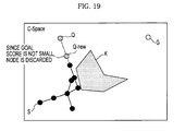
As shown in FIG. 29, a certain new point Q′ is selected. When the trees are expanded from the start point S and the waypoint K-1 to the certain point Q, the obstacle K is placed between the tree of the first section S1 and the certain new point Q′. Thus, the goal score is small. The tree is no longer expanded in the first section S1.
As shown in FIG. 30, even when the expansion of the tree in the second section S2 is finished, the tree is continuously expanded in the first section S1. At this time, if the solution of the inverse kinematics of the goal point is present, the tree is expanded in the first section S1 by inserting the goal point as the solution using a predetermined probability.
As shown in FIG. 31, even when the expansion of the tree in the second section S2 is finished, the tree is continuously expanded in the first section S1. FIG. 31 shows the case where the expansion of the tree is finished in the second section S2 and the tree is continuously expanded in the first section S1.
As shown in FIGS. 32 and 33, after the expansion of the tree is finished in the first section S1 and the second section S2, a final solution is searched for through graph search. FIG. 32 shows the case where the expansion of the tree is finished in the first section S1 and the second section S2 such that all the trees are completed. FIG. 33 shows the case where an overall path is formed through graph search.
FIG. 34 shows a process of selecting waypoints if a plurality of obstacles is present between a start point and a goal point in a C-Space according to an embodiment of the present invention. As shown in FIG. 34, obstacles which are located within a predetermined angle α from a straight line connected between the start point S and the goal point G are recognized as intermediate points 1, 2 and 3 (K1, K2 and K3), and certain points K1-1 and K1-2, K2-1 and K2-2 and K3-1 separated from the recognized intermediate points 1, 2 and 3 (K1, K2 and K3) by predetermined distances are selected. It is to be noted that intermediate points 1, 2 and 3 representing obstacles K1, K2 and K3 are merely representative and the waypoints which are separated from intermediate points 1, 2 and 3 representing the obstacles by predetermined distances may be separated from any of a plurality of points on the obstacle in the C-Space. Thus, the intermediate points 1, 2 and 3 may be center points of the obstacles in the C-Space or may be points located at any position within the representations of the obstacles. A point where the start point S and the points K2-1 and K2-2 selected at the intermediate point 2 (K2) are viewed is selected as the waypoint of the points K1-1 and K1-2 selected at the intermediate point 1 (K1), a point where the points K1-1 and K1-2 selected at the intermediate point 1 (K1) and the point K3-1 selected at the intermediate point 3 (K3) are viewed is selected as the waypoint of the points K2-1 and K2-2 selected at the intermediate point 2 (K2), and a point where the points K2-1 and K2-2 selected at the intermediate point 2 (K2) and the target point G are viewed is selected as the waypoint of the point K3-1 selected at the intermediate point 3 (K3).
As shown in FIG. 35, the goal score condition is applied to the waypoints of the intermediate points K1, K2 and K3 so as to search for a waypoint having a smallest goal score. At this time, a section from the start point S to the goal point G may be divided into a first section S1 from the start point to a first waypoint K1-1, a second section S2 from the first waypoint K1-1 to a second waypoint K2-1, a third section S3 from the second waypoint K2-1 to a third waypoint K3-1, and a fourth section S4 from the third waypoint K3-1 to the goal point G. At this time, if it is assumed that the solution of inverse kinematics is present in the start point S, the second waypoint K2-1 and the third waypoint K3-1 of the first section S1, the second section S2 and the fourth section S4 denoted by a solid line and the solution of inverse kinematics is not present in the second waypoint K2-1 of the third section S3 denoted by a dotted line, the trees are simultaneously expanded in the first section S1, the second section S2 and the fourth section S4. In the third section, the tree is expanded after the expansion of the tree in the second section S2 is finished.
FIGS. 36 to 39 show the state in which the path is completed by expanding the tree in the third section S3 after the expansion of the trees in the first section S1, the second section S2 and the fourth section S4 is finished.
As shown in FIG. 36, the trees are simultaneously expanded in the first section S1, the second section S2 and the fourth section S4. At this time, if a certain point Q is used, since the goal score is decreased only in the first section S1 and the second section S2, the trees are simultaneously expanded only in the first section S1 and the second section S2.
As shown in FIG. 37, after the simultaneous expansion of the trees in the first section S1 and the second section S2 is finished, the tree is expanded in the fourth section S4.
As shown in FIG. 38, after the expansion of the tree in the fourth section S4 is finished, the tree is expanded in the third section S3. At this time, the tree is expanded in a state in which the last node of the second section S2 is selected as an initial configuration.
As shown in FIG. 39, if the solutions of all the sections are searched for, a final tree is formed using a graph search algorithm so as to complete the generation of the path.
As shown in FIGS. 40 and 41, if the above-described method is not used as shown in FIG. 40 when the manipulator 130 grasps a ball C while avoiding a cylinder K corresponding to an obstacle, the manipulator 130 may not grasp the ball in a manner of passing the upper end of the cylinder K. However, if the above-described method is used, the manipulator 130 may pass the upper end of the cylinder K so as to grasp the ball. Therefore, a time consumed to grasp the ball may be shortened.
FIG. 42 is a flowchart illustrating a method of planning a motion path of a robot according to an embodiment.
Referring to FIG. 42, the method of planning the path of the manipulator 130 of the robot includes recognizing information given when the manipulator 130 performs the task command, that is, the configuration (start point S) at the initial position of the manipulator 130 before performing the task command, the configuration (goal point G) at the goal position of the manipulator 130 where the task command may be performed, and the obstacle between the start point S and the goal point G in the C-Space (300); setting the goal function which is the function according to the distance and direction difference between the start point S and the goal point G (301); recognizing the obstacle within the predetermined angle α from the straight line connected between the start point S and the goal point G as the intermediate point K (302); selecting the plurality of waypoints K-1 and K-2 separated from the intermediate point K by the predetermined distances and selecting the point having the smallest goal score from the waypoints of the intermediate point as the final waypoint K-1 or K-2 (303); obtaining the solution of inverse kinematics of the selected final waypoint (304); dividing the section from the start point S to the goal point G into a plurality of sections using the selected final waypoint of the intermediate point and setting the start points of the divided sections depending on whether or not the solution of inverse kinematics is present (305); selecting a certain point in the C-Space (306); selecting nodes each having a smallest goal score in the sections (307); connecting the selected nodes to the certain point by a virtual line (308); simultaneously expanding the trees in the sections having the solution of inverse kinematics using the BF-RRT algorithm (309); determining whether the goal point is reached (310); determining whether there is a section in which the expansion of the tree is not finished (311); expanding the tree in the section in which the expansion of the tree is not finished (312); and generating a final tree so as to generate a path (313).
One or more of units/hardware described in the application may also be configured to act as one or more software modules in order to perform the operations of the above-described embodiments and may cause a general purpose computer or processor or a particular machine to perform any of the operations discussed above.
Aspects of the present at least one embodiment can also be embodied as computer-readable codes on a computer-readable medium. Also, codes and code segments to accomplish the present at least one embodiment can be easily construed by programmers skilled in the art to which the present invention pertains. The computer-readable medium may be a computer-readable storage medium, which is any data storage device that can store data which can be thereafter read by a computer system or computer code processing apparatus. Examples of the computer-readable storage medium include read-only memory (ROM), random-access memory (RAM), CD-ROMs, magnetic tapes, floppy disks, and optical data storage devices. The computer-readable medium can also be distributed over network-coupled computer systems so that the computer-readable code is stored and executed in a distributed fashion.
Although a few embodiments have been shown and described, it would be appreciated by those skilled in the art that changes may be made in these embodiments without departing from the principles and spirit of the invention, the scope of which is defined in the claims and their equivalents.

Claims (4)

What is claimed is:
1. A method of planning a path of a robot, the robot including an user interface, a memory, one or more processors, a manipulator, and a driving unit, the method comprising:
receiving a task command through the user interface;
forming, by the one or more processors configured to execute computer-readable instructions stored in the memory, a configuration space to generate a motion path of the manipulator;
recognizing, by the one or more processors, one or more obstacles between a start point and a goal point of the configuration space;
identifying, by the one or more processors, each of the one or more obstacles as intermediate points, and for each intermediate point, selecting, by the one or more processors, a waypoint having a smallest goal score from a plurality of waypoints located at predetermined distances from the respective intermediate point;
dividing, by the one or more processors, a section from the start point to the goal point into a plurality of sections based on the selected one or more waypoints;
determining, by the one or more processors, whether a solution of inverse kinematics of the selected one or more waypoints is present;
simultaneously expanding, by the one or more processors, trees with respect to sections each having a selected waypoint with a solution of inverse kinematics, toward a randomly selected sample point;
expanding, by the one or more processors, a tree, after the simultaneous expansion of the trees is finished in the sections each having the waypoint with the solution of inverse kinematics, with respect to a section having a waypoint without a solution of inverse kinematics, to generate a search graph; and
connecting, by the one or more processors, the start point and the goal point using the search graph to generate an optimal path to avoid the one or more obstacles,
controlling, by the one or more processors, the driving unit to drive the manipulator to move along the generated optimal path
wherein the generating the search graph includes randomly sampling at least one point in the configuration space, searching for a node having a smallest goal score, connecting the at least one sampled point with the node having the smallest goal score, expanding a tree such that the node reaches the goal point through the at least one waypoint, and generating the search graph,
wherein the selecting a waypoint includes recognizing, using the one or more processors, one of the one or more obstacles located within a predetermined angle from a straight line connected between the start point and the goal point of the configuration space as at least one intermediate point, selecting certain points separated from the intermediate point by predetermined distances, respectively connecting the certain points to the start point and the goal point, and selecting one of the certain points, in which the one of the one or more obstacles is not present, as the waypoint, and
wherein the node having the smallest goal score is selected from the tree using a goal function composed of a function of a distance from the goal point to an end-effector and a directional vector so as to expand the tree.
2. The method according to claim 1, wherein the start point is a node where a configuration at an initial position before the manipulator performs a task is formed in the configuration space.
3. The method according to claim 2, wherein the goal point is a node where a configuration at a goal position where the manipulator performs a task is formed in the configuration space.
4. An apparatus to plan a motion path of a robot, the apparatus comprising:
an user interface unit configured to for an user to input a task command;
a driving unit;
a manipulator;
a memory configured to store computer-readable instructions; and
one or more processors, in response to the task command and by executing computer-readable instructions, configured to,
recognize a start point and a goal point respectively corresponding to an initial configuration and a goal configuration of a manipulator,
recognize one or more obstacles located between the start point and the goal point,
form a configuration space,
identify the one or more obstacles located within a predetermined angle from a straight line connected between the start point and the goal point of the configuration space as intermediate points,
for each of the intermediate points,
select a waypoint having a smallest goal score from a plurality of waypoints located at predetermined distances from a corresponding one of the intermediate points,
divide a section from the start point to the goal point into a plurality of sections based on the selected waypoint,
simultaneously expand trees with respect to sections each having a waypoint with a solution of inverse kinematics toward a randomly selected sample point, and
expand a tree after the simultaneous expansion of the trees is finished in the sections each having the waypoint with the solution of inverse kinematics, with respect to a section having a waypoint without a solution of inverse kinematics, to generate a search graph, and to connect the start point and the goal point using the search graph to generate an optimal path to avoid the one or more obstacles, and
control the driving unit to drive the manipulator to move along the optimal path,
wherein the one or more processors are further configured to,
randomly sample at least one point in the configuration space, search for a node having a smallest goal score,
connect the at least one sampled point with the node having the smallest goal score,
expand a tree such that the node reaches the goal point through the at least one waypoint, and
generate a search graph,
wherein the one or more processors are further configured to, for one of the intermediate points,
select certain points separated from the one of the intermediate points by predetermined distances,
respectively connect the certain points to the start point and the goal point, and
select one of the certain points, in which the one or more obstacles are not present, as one of the at least one waypoint, and
wherein the one or more processors are further configured to select the node having the smallest goal score from the tree using a goal function composed of a function of a distance from the goal point to an end-effector and a directional vector so as to expand the tree.
US12/805,270 2009-08-10 2010-07-21 Method and apparatus to plan motion path of robot Active 2032-02-02 US9411335B2 (en)

Applications Claiming Priority (2)

Application Number Priority Date Filing Date Title
KR1020090073257A KR101667029B1 (en) 2009-08-10 2009-08-10 Method and apparatus of path planing for a robot
KR10-2009-73257 2009-08-10

Publications (2)

Publication Number Publication Date
US20110035087A1 US20110035087A1 (en) 2011-02-10
US9411335B2 true US9411335B2 (en) 2016-08-09

Family

ID=43535442

Family Applications (1)

Application Number Title Priority Date Filing Date
US12/805,270 Active 2032-02-02 US9411335B2 (en) 2009-08-10 2010-07-21 Method and apparatus to plan motion path of robot

Country Status (2)

Country Link
US (1) US9411335B2 (en)
KR (1) KR101667029B1 (en)

Cited By (8)

* Cited by examiner, † Cited by third party
Publication number Priority date Publication date Assignee Title
US20200118446A1 (en) * 2018-10-12 2020-04-16 Aurora Flight Sciences Corporation Trajectory Planner for a Vehicle
US10678264B2 (en) * 2018-10-10 2020-06-09 Midea Group Co., Ltd. Method and system for providing remote robotic control
US10803314B2 (en) 2018-10-10 2020-10-13 Midea Group Co., Ltd. Method and system for providing remote robotic control
US10816994B2 (en) 2018-10-10 2020-10-27 Midea Group Co., Ltd. Method and system for providing remote robotic control
CN112223291A (en) * 2020-10-21 2021-01-15 哈工大机器人(合肥)国际创新研究院 Mechanical arm obstacle avoidance method and device based on three-dimensional task space constraint
US11407109B2 (en) 2020-04-16 2022-08-09 Boston Dynamics, Inc. Global arm path planning with roadmaps and precomputed domains
WO2022173468A1 (en) * 2021-02-10 2022-08-18 Intrinsic Innovation Llc Extensible underconstrained robotic motion planning
US11707843B2 (en) 2020-04-03 2023-07-25 Fanuc Corporation Initial reference generation for robot optimization motion planning

Families Citing this family (103)

* Cited by examiner, † Cited by third party
Publication number Priority date Publication date Assignee Title
KR101667030B1 (en) * 2009-08-10 2016-10-17 삼성전자 주식회사 Path planning apparatus of robot and method thereof
US8781629B2 (en) * 2010-09-22 2014-07-15 Toyota Motor Engineering & Manufacturing North America, Inc. Human-robot interface apparatuses and methods of controlling robots
KR101732902B1 (en) 2010-12-27 2017-05-24 삼성전자주식회사 Path planning apparatus of robot and method thereof
US20120306443A1 (en) * 2011-06-03 2012-12-06 GM Global Technology Operations LLC Automated charging for vehicle energy storage systems
CN102289553B (en) * 2011-09-26 2013-11-06 北京理工大学 Method and device for solving disassembly path of product parts
JP5724919B2 (en) * 2012-03-22 2015-05-27 トヨタ自動車株式会社 Orbit generation device, moving body, orbit generation method and program
JP2013246553A (en) * 2012-05-24 2013-12-09 Toyota Motor Corp Track planning device, track planning method and track planning program
DE102013207895A1 (en) * 2013-04-30 2014-10-30 Kuka Laboratories Gmbh Driverless transport vehicle, system with a computer and a driverless transport vehicle, method for operating a driverless transport vehicle
KR102165437B1 (en) * 2014-05-02 2020-10-14 한화디펜스 주식회사 Path planning apparatus of mobile robot
US9620022B2 (en) 2014-06-10 2017-04-11 Sikorsky Aircraft Corporation Aircraft motion planning method
CN104020769B (en) * 2014-06-13 2017-02-08 哈尔滨工程大学 Robot overall path planning method based on charge system search
US9375853B1 (en) * 2014-12-03 2016-06-28 Google Inc. Methods and systems to provide feedback based on a motion per path metric indicative of an effect of motion associated with components of a robotic device
US20170341235A1 (en) * 2016-05-27 2017-11-30 General Electric Company Control System And Method For Robotic Motion Planning And Control
US10884406B2 (en) 2015-08-03 2021-01-05 X-Control System Co., Ltd. Method and device for controlling movement of external device
KR101748632B1 (en) 2015-10-29 2017-06-20 한국과학기술연구원 Robot control system and method for planning driving path of robot
US20170165835A1 (en) * 2015-12-09 2017-06-15 Qualcomm Incorporated Rapidly-exploring randomizing feedback-based motion planning
CN107305382A (en) * 2016-04-21 2017-10-31 上海慧流云计算科技有限公司 A kind of self-navigation robot and automatic navigation method
US10353400B2 (en) * 2016-05-23 2019-07-16 Asustek Computer Inc. Navigation system and navigation method
US10054447B2 (en) 2016-08-17 2018-08-21 Sharp Laboratories Of America, Inc. Lazier graph-based path planning for autonomous navigation
CN106774314A (en) * 2016-12-11 2017-05-31 北京联合大学 A kind of home-services robot paths planning method based on run trace
CN106584461B (en) * 2016-12-21 2019-02-15 西安科技大学 The inverse kinematics personification arm configuration optimization method of seven degrees of freedom copy man mechanical arm under multi-constraint condition
CN106871897B (en) * 2016-12-30 2020-04-24 中国船舶重工集团公司第七0七研究所 Route making method for automatically associating waypoint library
WO2018143003A1 (en) * 2017-01-31 2018-08-09 株式会社安川電機 Robot path-generating device and robot system
CN106990777A (en) * 2017-03-10 2017-07-28 江苏物联网研究发展中心 Robot local paths planning method
CN106695802A (en) * 2017-03-19 2017-05-24 北京工业大学 Improved RRT<*> obstacle avoidance motion planning method based on multi-degree-of-freedom mechanical arm
CN107085437A (en) * 2017-03-20 2017-08-22 浙江工业大学 A kind of unmanned aerial vehicle flight path planing method based on EB RRT
CN108692724A (en) * 2017-04-10 2018-10-23 中兴通讯股份有限公司 A kind of indoor navigation method and device
CN107677285B (en) * 2017-04-11 2019-05-28 平安科技(深圳)有限公司 The path planning system and method for robot
CN106969770B (en) * 2017-05-31 2021-04-06 深圳中智卫安机器人技术有限公司 Robot and navigation method and computer readable storage medium thereof
WO2019014274A1 (en) 2017-07-10 2019-01-17 Hypertherm, Inc. Computer-implemented methods and systems for generating material processing robotic tool paths
CN109807880B (en) * 2017-11-22 2021-02-02 海安苏博机器人科技有限公司 Inverse solution method and device of mechanical arm and robot
CN108237534B (en) * 2018-01-04 2020-04-03 清华大学深圳研究生院 Space obstacle avoidance trajectory planning method for continuous mechanical arm
CN108544490B (en) * 2018-01-05 2021-02-23 广东雷洋智能科技股份有限公司 Obstacle avoidance method for unmanned intelligent robot road
CN108195383A (en) * 2018-03-13 2018-06-22 济南大学 A kind of unmanned scraper paths planning method in underground based on improvement RRT algorithms
CN108717302B (en) * 2018-05-14 2021-06-25 平安科技(深圳)有限公司 Method and device for robot to follow person, storage medium and robot
CN108762270B (en) * 2018-06-01 2021-04-27 上海理工大学 Improved path planning algorithm for variable probability bidirectional fast search random tree
KR102090590B1 (en) * 2018-06-08 2020-04-23 엘지전자 주식회사 Robot of moving waypoints based on obstace avoidance and method of moving
CN108818530B (en) * 2018-06-12 2020-05-15 西安交通大学 Mechanical arm grabbing scattered stacking piston motion planning method based on improved RRT algorithm
CN108972549B (en) * 2018-07-03 2021-02-19 华南理工大学 Industrial mechanical arm real-time obstacle avoidance planning and grabbing system based on Kinect depth camera
CN109059903A (en) * 2018-08-21 2018-12-21 北京云迹科技有限公司 Paths planning method and distributed robot
CN110377019B (en) * 2018-09-05 2022-08-12 北京京东乾石科技有限公司 Route generation method and device
GB2577915B (en) * 2018-10-10 2021-06-16 Dyson Technology Ltd Path planning
EP3639983A1 (en) * 2018-10-18 2020-04-22 Technische Universität München Anti-collision safety measures for a reconfigurable modular robot
CN109542117B (en) * 2018-10-19 2023-08-11 哈尔滨工业大学(威海) Underwater vehicle rolling planning algorithm based on improved RRT
CN109116858B (en) * 2018-11-07 2021-09-07 诺亚机器人科技(上海)有限公司 Obstacle-detouring path planning method and system on designated path
CN109781126A (en) * 2018-12-30 2019-05-21 芜湖哈特机器人产业技术研究院有限公司 A kind of global static path planning method based on vector method
CN109855622B (en) * 2019-01-07 2021-06-11 上海岚豹智能科技有限公司 Path searching method and device for mobile robot
CN109737967A (en) * 2019-02-28 2019-05-10 中国科学院深圳先进技术研究院 Unmanned plane paths planning method, device, storage medium and computer equipment
KR102190102B1 (en) * 2019-03-08 2020-12-11 (주)아이로텍 Collision avoidance simulation system: A method of displaying a guidance tool for robot routing to avoid collision
KR102215618B1 (en) * 2019-03-12 2021-02-15 엘지전자 주식회사 Carts moving parallel to the installation and method of movement
KR102170752B1 (en) * 2019-03-13 2020-10-27 (주)아이로텍 Obstacle avoidance pathe generation simulation system
CN109877836B (en) * 2019-03-13 2021-06-08 浙江大华技术股份有限公司 Path planning method and device, mechanical arm controller and readable storage medium
CN111857112B (en) * 2019-04-12 2023-11-14 广州汽车集团股份有限公司 Automobile local path planning method and electronic equipment
KR102049962B1 (en) * 2019-04-17 2019-11-28 주식회사 트위니 Sampling based optimal tree planning method and recording medium storing program for executing the same, and computer program stored in recording medium for executing the same
CN110118559B (en) * 2019-04-30 2021-05-25 厦门大学 Navigation robot dynamic obstacle avoidance method and device based on variable probability strategy
CN110340890A (en) * 2019-06-27 2019-10-18 北京控制工程研究所 A kind of space manipulator overall situation is without touching Trajectory Planning System
CN110370274A (en) * 2019-07-03 2019-10-25 浙江大学 A kind of mechanical arm dynamic obstacle avoidance control method based on Fast marching tree
CN111338334A (en) * 2019-10-25 2020-06-26 常州信息职业技术学院 Assembly path planning method based on multi-factor cost guidance in virtual assembly simulation
CN110823240B (en) * 2019-11-19 2021-05-11 齐鲁工业大学 Following robot path planning method and system with course constraint
CN110906947B (en) * 2019-12-04 2022-05-17 山东省科学院自动化研究所 Slime RRT navigation method and system based on two-dimensional static path planning
CN111060103B (en) * 2019-12-11 2021-12-10 安徽工程大学 Path planning method for local dynamic optimization and obstacle avoidance
CN111413962B (en) * 2020-01-15 2022-11-11 杭州电子科技大学 Search and rescue robot target search method based on path passing probability
CN111240334B (en) * 2020-01-18 2023-06-23 山东交通学院 Automatic collision avoidance route planning method and model for ship navigation
CN111256722B (en) * 2020-02-28 2023-08-01 广东博智林机器人有限公司 Path planning method, device, equipment and storage medium
KR102296694B1 (en) * 2020-03-10 2021-08-31 엘지전자 주식회사 Moving robot
CN111650941B (en) * 2020-06-10 2023-05-02 湖南爱米家智能科技有限公司 RRT-Connect-based improved medical mobile robot path planning method
CN113858188A (en) * 2020-06-30 2021-12-31 罗伯特·博世有限公司 Industrial robot gripping method and apparatus, computer storage medium, and industrial robot
US11737627B2 (en) * 2020-10-03 2023-08-29 Viabot Inc. Methods for setting and programming zoning for use by autonomous modular robots
CN112515554B (en) * 2020-10-14 2022-05-03 深圳市银星智能科技股份有限公司 Robot walking path searching method and electronic equipment
CN112306067B (en) * 2020-11-13 2022-11-18 湖北工业大学 Global path planning method and system
CN112380655A (en) * 2020-11-20 2021-02-19 华南理工大学 Robot inverse kinematics solving method based on RS-CMSA algorithm
CN112462785B (en) * 2020-12-04 2022-06-03 厦门大学 Mobile robot path planning method and device and storage medium
CN112923944A (en) * 2021-01-29 2021-06-08 的卢技术有限公司 Automatic driving path planning method and system and computer readable storage medium
CN112987740B (en) * 2021-03-01 2023-08-18 北方工业大学 Mobile robot path planning control method
CN113050627A (en) * 2021-03-02 2021-06-29 北京旷视机器人技术有限公司 Path planning method and device, mobile robot and computer storage medium
CN113009916A (en) * 2021-03-08 2021-06-22 珠海市一微半导体有限公司 Path planning method, chip and robot based on global map exploration
US11945117B2 (en) 2021-03-10 2024-04-02 Samsung Electronics Co., Ltd. Anticipating user and object poses through task-based extrapolation for robot-human collision avoidance
CN113064426B (en) * 2021-03-17 2022-03-15 安徽工程大学 Intelligent vehicle path planning method for improving bidirectional fast search random tree algorithm
US11833691B2 (en) * 2021-03-30 2023-12-05 Samsung Electronics Co., Ltd. Hybrid robotic motion planning system using machine learning and parametric trajectories
CN112947489B (en) * 2021-04-08 2022-11-22 华东理工大学 Method and device for planning collision-free path of welding robot in complex environment
CN113103236B (en) * 2021-04-22 2022-06-10 山东大学 Rapid and gradual optimal mechanical arm obstacle avoidance path planning method
CN113110497A (en) * 2021-05-08 2021-07-13 珠海市一微半导体有限公司 Navigation path-based edge obstacle-detouring path selection method, chip and robot
CN113352319B (en) * 2021-05-08 2022-10-21 上海工程技术大学 Redundant mechanical arm obstacle avoidance trajectory planning method based on improved fast expansion random tree
CN113253729B (en) * 2021-05-18 2023-07-25 中国工商银行股份有限公司 Path planning method, device and storage medium of cross-zone inspection robot
US20220388171A1 (en) * 2021-06-03 2022-12-08 Intrinsic Innovation Llc Robotic workspace introspection via force feedback
CN113219998B (en) * 2021-06-15 2022-07-05 合肥工业大学 Improved bidirectional-RRT-based vehicle path planning method
CN113934206B (en) * 2021-07-22 2024-01-16 浙江科技学院 Mobile robot path planning method, mobile robot path planning device, computer equipment and storage medium
CN113485241B (en) * 2021-07-28 2022-11-01 华南理工大学 Off-line scanning path planning method for welding robot based on line-structured light sensor
JP2023060736A (en) * 2021-10-18 2023-04-28 株式会社東芝 Route planning device, route planning method, and route planning program
CN113885509B (en) * 2021-10-21 2024-02-06 广东电网有限责任公司广州供电局 Emergency power supply vehicle path planning method, device, equipment and storage medium
CN113792109B (en) * 2021-11-18 2022-02-11 上海景吾智能科技有限公司 Path planning method, path planning system, robot, and storage medium
CN114161416B (en) * 2021-12-06 2023-04-28 贵州大学 Robot path planning method based on potential function
CN114485703B (en) * 2021-12-31 2024-01-30 杭州电子科技大学 Path planning method based on myxobacteria and random search tree
CN114489052A (en) * 2021-12-31 2022-05-13 杭州电子科技大学 Path planning method for improving RRT algorithm reconnection strategy
CN114700937B (en) * 2022-01-13 2024-02-13 深圳市越疆科技有限公司 Mechanical arm, motion path planning method thereof, control system, medium and robot
CN114510056A (en) * 2022-02-21 2022-05-17 上海机器人产业技术研究院有限公司 Stable moving global path planning method for indoor mobile robot
CN114323028B (en) * 2022-03-16 2022-06-07 中南大学 Path planning method, system, device and medium for self-adaptive map
CN114378834B (en) * 2022-03-23 2022-06-17 季华实验室 Mechanical arm obstacle avoidance path planning method and device, electronic equipment and storage medium
CN114764250A (en) * 2022-04-27 2022-07-19 福州大学 Non-uniform sampling motion planning method based on expansion guidance
CN114952839B (en) * 2022-05-27 2024-02-06 西南交通大学 Cloud edge cooperation-based two-stage robot motion decision system
CN115206157A (en) * 2022-08-05 2022-10-18 白杨时代(北京)科技有限公司 Unmanned underwater vehicle path finding training method and device and unmanned underwater vehicle
CN116382309A (en) * 2023-06-06 2023-07-04 康复大学(筹) Robot path planning algorithm based on cylindrical heuristic sampling
CN117124335B (en) * 2023-10-25 2024-01-05 山东工商学院 Improved RRT path planning method based on path marking backtracking strategy

Citations (18)

* Cited by examiner, † Cited by third party
Publication number Priority date Publication date Assignee Title
US4772831A (en) * 1986-11-20 1988-09-20 Unimation, Inc. Multiaxis robot control having improved continuous path operation
US5835684A (en) * 1994-11-09 1998-11-10 Amada Company, Ltd. Method for planning/controlling robot motion
US5999881A (en) * 1997-05-05 1999-12-07 General Electric Company Automated path planning
US6166746A (en) * 1994-07-21 2000-12-26 Matsushita Electric Industrial Co., Ltd. Three-dimensional image processing apparatus for jointed objects
US6728581B1 (en) * 1988-03-09 2004-04-27 North American Philips Corporation Differential budding: method and apparatus for path planning with moving obstacles and goals
US20060190136A1 (en) * 2005-02-24 2006-08-24 Paragon Technical Services, Inc. Method and system for controlling a manipulator
US20060241813A1 (en) * 2005-04-22 2006-10-26 Applied Materials, Inc. Optimized cluster tool transfer process and collision avoidance design
JP2008105132A (en) 2006-10-25 2008-05-08 Toyota Motor Corp Method and apparatus for producing path of arm in joint space
US20080306628A1 (en) * 2007-06-08 2008-12-11 Honda Motor Co., Ltd. Multi-Modal Push Planner for Humanoid Robots
US7512485B2 (en) * 2005-03-29 2009-03-31 International Business Machines Corporation Method for routing multiple paths through polygonal obstacles
US20100114338A1 (en) * 2008-10-31 2010-05-06 Gm Global Technology Operations, Inc. Multi-goal path planning of welding robots with automatic sequencing
US20100121148A1 (en) * 2008-11-11 2010-05-13 Intuitive Surgical, Inc. Method and system for steerable medical device path definition and following during insertion and retraction
US20100168950A1 (en) * 2009-01-01 2010-07-01 Masakuni Nagano Path Planning Device, Path Planning Method, and Computer Program
US7844398B2 (en) * 2008-07-09 2010-11-30 Panasonic Corporation Path risk evaluating apparatus
US20110035050A1 (en) * 2009-08-10 2011-02-10 Samsung Electronics Co., Ltd. Method and apparatus to plan motion path of robot
US8311731B2 (en) * 2007-03-23 2012-11-13 Honda Research Institute Europe Gmbh Robots with collision avoidance functionality
US8483874B2 (en) * 2009-11-02 2013-07-09 Samsung Electronics Co., Ltd. Path planning apparatus of robot and method and computer-readable medium thereof
US8972057B1 (en) * 2013-01-09 2015-03-03 The Boeing Company Systems and methods for generating a robotic path plan in a confined configuration space

Patent Citations (20)

* Cited by examiner, † Cited by third party
Publication number Priority date Publication date Assignee Title
US4772831A (en) * 1986-11-20 1988-09-20 Unimation, Inc. Multiaxis robot control having improved continuous path operation
US6728581B1 (en) * 1988-03-09 2004-04-27 North American Philips Corporation Differential budding: method and apparatus for path planning with moving obstacles and goals
US6166746A (en) * 1994-07-21 2000-12-26 Matsushita Electric Industrial Co., Ltd. Three-dimensional image processing apparatus for jointed objects
US5835684A (en) * 1994-11-09 1998-11-10 Amada Company, Ltd. Method for planning/controlling robot motion
US6493607B1 (en) * 1994-11-09 2002-12-10 Amada America, Inc. Method for planning/controlling robot motion
US5999881A (en) * 1997-05-05 1999-12-07 General Electric Company Automated path planning
US20060190136A1 (en) * 2005-02-24 2006-08-24 Paragon Technical Services, Inc. Method and system for controlling a manipulator
US7512485B2 (en) * 2005-03-29 2009-03-31 International Business Machines Corporation Method for routing multiple paths through polygonal obstacles
US20060241813A1 (en) * 2005-04-22 2006-10-26 Applied Materials, Inc. Optimized cluster tool transfer process and collision avoidance design
JP2008105132A (en) 2006-10-25 2008-05-08 Toyota Motor Corp Method and apparatus for producing path of arm in joint space
US8311731B2 (en) * 2007-03-23 2012-11-13 Honda Research Institute Europe Gmbh Robots with collision avoidance functionality
US20080306628A1 (en) * 2007-06-08 2008-12-11 Honda Motor Co., Ltd. Multi-Modal Push Planner for Humanoid Robots
US7844398B2 (en) * 2008-07-09 2010-11-30 Panasonic Corporation Path risk evaluating apparatus
US20100114338A1 (en) * 2008-10-31 2010-05-06 Gm Global Technology Operations, Inc. Multi-goal path planning of welding robots with automatic sequencing
US20100121148A1 (en) * 2008-11-11 2010-05-13 Intuitive Surgical, Inc. Method and system for steerable medical device path definition and following during insertion and retraction
US20100168950A1 (en) * 2009-01-01 2010-07-01 Masakuni Nagano Path Planning Device, Path Planning Method, and Computer Program
US8185265B2 (en) * 2009-01-01 2012-05-22 Sony Corporation Path planning device, path planning method, and computer program
US20110035050A1 (en) * 2009-08-10 2011-02-10 Samsung Electronics Co., Ltd. Method and apparatus to plan motion path of robot
US8483874B2 (en) * 2009-11-02 2013-07-09 Samsung Electronics Co., Ltd. Path planning apparatus of robot and method and computer-readable medium thereof
US8972057B1 (en) * 2013-01-09 2015-03-03 The Boeing Company Systems and methods for generating a robotic path plan in a confined configuration space

Non-Patent Citations (3)

* Cited by examiner, † Cited by third party
Title
http://ieeexplore.ieee.org/stamp/stamp.jsp?tp=&arnumber=1641979. *
Korean Office Action dated Dec. 18, 2015 for corresponding KR Application No. 10-2009-0073257.
Kuffner, Jr. et al. "RRT-Connect: An Efficient Approach to Single-Query Path Planning," Proc. 2000 IEEE Int'l Conf. on Robotics and Automation (ICRA 2000). 2000.

Cited By (13)

* Cited by examiner, † Cited by third party
Publication number Priority date Publication date Assignee Title
US10678264B2 (en) * 2018-10-10 2020-06-09 Midea Group Co., Ltd. Method and system for providing remote robotic control
US10803314B2 (en) 2018-10-10 2020-10-13 Midea Group Co., Ltd. Method and system for providing remote robotic control
US10816994B2 (en) 2018-10-10 2020-10-27 Midea Group Co., Ltd. Method and system for providing remote robotic control
US11557210B2 (en) 2018-10-12 2023-01-17 The Boeing Company Trajectory planner for a vehicle
US10878706B2 (en) * 2018-10-12 2020-12-29 Aurora Flight Sciences Corporation Trajectory planner for a vehicle
US20200118446A1 (en) * 2018-10-12 2020-04-16 Aurora Flight Sciences Corporation Trajectory Planner for a Vehicle
US11707843B2 (en) 2020-04-03 2023-07-25 Fanuc Corporation Initial reference generation for robot optimization motion planning
US11407109B2 (en) 2020-04-16 2022-08-09 Boston Dynamics, Inc. Global arm path planning with roadmaps and precomputed domains
US11654559B2 (en) 2020-04-16 2023-05-23 Boston Dynamics, Inc. Global arm path planning with roadmaps and precomputed domains
CN112223291B (en) * 2020-10-21 2022-02-11 哈工大机器人(合肥)国际创新研究院 Mechanical arm obstacle avoidance method and device based on three-dimensional task space constraint
CN112223291A (en) * 2020-10-21 2021-01-15 哈工大机器人(合肥)国际创新研究院 Mechanical arm obstacle avoidance method and device based on three-dimensional task space constraint
US11518024B2 (en) 2021-02-10 2022-12-06 Intrinsic Innovation Llc Extensible underconstrained robotic motion planning
WO2022173468A1 (en) * 2021-02-10 2022-08-18 Intrinsic Innovation Llc Extensible underconstrained robotic motion planning

Also Published As

Publication number Publication date
KR20110015833A (en) 2011-02-17
US20110035087A1 (en) 2011-02-10
KR101667029B1 (en) 2016-10-17

Similar Documents

Publication Publication Date Title
US9411335B2 (en) Method and apparatus to plan motion path of robot
US8825209B2 (en) Method and apparatus to plan motion path of robot
US9044862B2 (en) Path planning apparatus and method for robot
US8483874B2 (en) Path planning apparatus of robot and method and computer-readable medium thereof
CN110228069B (en) Online obstacle avoidance motion planning method for mechanical arm
US8818555B2 (en) Path planning apparatus of robot and method and computer-readable medium thereof
Stavridis et al. Bimanual assembly of two parts with relative motion generation and task related optimization
KR101732902B1 (en) Path planning apparatus of robot and method thereof
Shkolnik et al. Path planning in 1000+ dimensions using a task-space Voronoi bias
Zacharias et al. Making planned paths look more human-like in humanoid robot manipulation planning
US8666548B2 (en) Path planning apparatus of robot and method thereof
US9043030B2 (en) Manipulator and path generation method thereof
US20100023164A1 (en) Route creation method and route creation device
Luo et al. Collision-free path-planning for six-DOF serial harvesting robot based on energy optimal and artificial potential field
Al-Sharo et al. Generalized Procedure for Determining the Collision-Free Trajectory for a Robotic Arm
JP4304495B2 (en) Route planning method
Marino et al. On the problem of moving objects with autonomous robots: A unifying high-level planning approach
Koo et al. Development of a wire harness assembly motion planner for redundant multiple manipulators
Vahrenkamp et al. Adaptive motion planning for humanoid robots
Tang et al. Coordinated motion planning of dual-arm space robot with deep reinforcement learning
Rasheed et al. Path planning of a mobile cable-driven parallel robot in a constrained environment
Zahid et al. Investigation of branch accessibility with a robotic pruner for pruning apple trees
Qian et al. Path planning approach for redundant manipulator based on Jacobian pseudoinverse-RRT algorithm
Kawabe et al. A flexible collision-free trajectory planning for multiple robot arms by combining Q-learning and RRT
Li et al. An Efficient Approach for Solving Robotic Task Sequencing Problems Considering Spatial Constraint

Legal Events

Date Code Title Description
AS Assignment

Owner name: SAMSUNG ELECTRONICS CO., LTD., KOREA, REPUBLIC OF

Free format text: ASSIGNMENT OF ASSIGNORS INTEREST;ASSIGNORS:KIM, MYUNG HEE;ROH, KYUNG SHIK;LIM, SAN;AND OTHERS;REEL/FRAME:024770/0649

Effective date: 20100721

STCF Information on status: patent grant

Free format text: PATENTED CASE

FEPP Fee payment procedure

Free format text: PAYOR NUMBER ASSIGNED (ORIGINAL EVENT CODE: ASPN); ENTITY STATUS OF PATENT OWNER: LARGE ENTITY

MAFP Maintenance fee payment

Free format text: PAYMENT OF MAINTENANCE FEE, 4TH YEAR, LARGE ENTITY (ORIGINAL EVENT CODE: M1551); ENTITY STATUS OF PATENT OWNER: LARGE ENTITY

Year of fee payment: 4

MAFP Maintenance fee payment

Free format text: PAYMENT OF MAINTENANCE FEE, 8TH YEAR, LARGE ENTITY (ORIGINAL EVENT CODE: M1552); ENTITY STATUS OF PATENT OWNER: LARGE ENTITY

Year of fee payment: 8