US9408286B1 - Short pulse neutron generator - Google Patents
Short pulse neutron generator Download PDFInfo
- Publication number
- US9408286B1 US9408286B1 US14/016,609 US201314016609A US9408286B1 US 9408286 B1 US9408286 B1 US 9408286B1 US 201314016609 A US201314016609 A US 201314016609A US 9408286 B1 US9408286 B1 US 9408286B1
- Authority
- US
- United States
- Prior art keywords
- conductive plate
- electrode
- face
- cavity
- ions
- Prior art date
- Legal status (The legal status is an assumption and is not a legal conclusion. Google has not performed a legal analysis and makes no representation as to the accuracy of the status listed.)
- Active, expires
Links
- 150000002500 ions Chemical class 0.000 claims abstract description 109
- 239000003989 dielectric material Substances 0.000 claims abstract description 11
- 229910052805 deuterium Inorganic materials 0.000 claims description 20
- YZCKVEUIGOORGS-OUBTZVSYSA-N Deuterium Chemical compound [2H] YZCKVEUIGOORGS-OUBTZVSYSA-N 0.000 claims description 19
- 229910052722 tritium Inorganic materials 0.000 claims description 16
- YZCKVEUIGOORGS-NJFSPNSNSA-N Tritium Chemical compound [3H] YZCKVEUIGOORGS-NJFSPNSNSA-N 0.000 claims description 15
- 238000000034 method Methods 0.000 description 19
- 238000005516 engineering process Methods 0.000 description 5
- 230000000977 initiatory effect Effects 0.000 description 4
- 238000010586 diagram Methods 0.000 description 3
- 238000012986 modification Methods 0.000 description 3
- 230000004048 modification Effects 0.000 description 3
- RTAQQCXQSZGOHL-UHFFFAOYSA-N Titanium Chemical compound [Ti] RTAQQCXQSZGOHL-UHFFFAOYSA-N 0.000 description 2
- 230000004075 alteration Effects 0.000 description 2
- 239000000463 material Substances 0.000 description 2
- 229910052751 metal Inorganic materials 0.000 description 2
- 239000002184 metal Substances 0.000 description 2
- 229910052706 scandium Inorganic materials 0.000 description 2
- SIXSYDAISGFNSX-UHFFFAOYSA-N scandium atom Chemical compound [Sc] SIXSYDAISGFNSX-UHFFFAOYSA-N 0.000 description 2
- 239000007787 solid Substances 0.000 description 2
- 239000010936 titanium Substances 0.000 description 2
- 229910052719 titanium Inorganic materials 0.000 description 2
- RYGMFSIKBFXOCR-UHFFFAOYSA-N Copper Chemical compound [Cu] RYGMFSIKBFXOCR-UHFFFAOYSA-N 0.000 description 1
- 229910052691 Erbium Inorganic materials 0.000 description 1
- 241000321453 Paranthias colonus Species 0.000 description 1
- XUIMIQQOPSSXEZ-UHFFFAOYSA-N Silicon Chemical compound [Si] XUIMIQQOPSSXEZ-UHFFFAOYSA-N 0.000 description 1
- 229910000831 Steel Inorganic materials 0.000 description 1
- 239000004020 conductor Substances 0.000 description 1
- 229910052802 copper Inorganic materials 0.000 description 1
- 239000010949 copper Substances 0.000 description 1
- 238000001514 detection method Methods 0.000 description 1
- -1 deuterium ions Chemical class 0.000 description 1
- 238000007599 discharging Methods 0.000 description 1
- UYAHIZSMUZPPFV-UHFFFAOYSA-N erbium Chemical compound [Er] UYAHIZSMUZPPFV-UHFFFAOYSA-N 0.000 description 1
- 230000004927 fusion Effects 0.000 description 1
- 239000011521 glass Substances 0.000 description 1
- 230000009931 harmful effect Effects 0.000 description 1
- 238000003384 imaging method Methods 0.000 description 1
- 230000003116 impacting effect Effects 0.000 description 1
- 238000004519 manufacturing process Methods 0.000 description 1
- 239000011159 matrix material Substances 0.000 description 1
- 238000012544 monitoring process Methods 0.000 description 1
- 239000003129 oil well Substances 0.000 description 1
- 229910052573 porcelain Inorganic materials 0.000 description 1
- 238000002601 radiography Methods 0.000 description 1
- 229910052710 silicon Inorganic materials 0.000 description 1
- 239000010703 silicon Substances 0.000 description 1
- 239000010959 steel Substances 0.000 description 1
- 239000010409 thin film Substances 0.000 description 1
- 238000011282 treatment Methods 0.000 description 1
Images


Classifications
-
- H—ELECTRICITY
- H05—ELECTRIC TECHNIQUES NOT OTHERWISE PROVIDED FOR
- H05H—PLASMA TECHNIQUE; PRODUCTION OF ACCELERATED ELECTRICALLY-CHARGED PARTICLES OR OF NEUTRONS; PRODUCTION OR ACCELERATION OF NEUTRAL MOLECULAR OR ATOMIC BEAMS
- H05H3/00—Production or acceleration of neutral particle beams, e.g. molecular or atomic beams
- H05H3/06—Generating neutron beams
-
- H—ELECTRICITY
- H05—ELECTRIC TECHNIQUES NOT OTHERWISE PROVIDED FOR
- H05H—PLASMA TECHNIQUE; PRODUCTION OF ACCELERATED ELECTRICALLY-CHARGED PARTICLES OR OF NEUTRONS; PRODUCTION OR ACCELERATION OF NEUTRAL MOLECULAR OR ATOMIC BEAMS
- H05H1/00—Generating plasma; Handling plasma
- H05H1/02—Arrangements for confining plasma by electric or magnetic fields; Arrangements for heating plasma
- H05H1/10—Arrangements for confining plasma by electric or magnetic fields; Arrangements for heating plasma using externally-applied magnetic fields only, e.g. Q-machines, Yin-Yang, base-ball
- H05H1/12—Arrangements for confining plasma by electric or magnetic fields; Arrangements for heating plasma using externally-applied magnetic fields only, e.g. Q-machines, Yin-Yang, base-ball wherein the containment vessel forms a closed or nearly closed loop
-
- H—ELECTRICITY
- H05—ELECTRIC TECHNIQUES NOT OTHERWISE PROVIDED FOR
- H05H—PLASMA TECHNIQUE; PRODUCTION OF ACCELERATED ELECTRICALLY-CHARGED PARTICLES OR OF NEUTRONS; PRODUCTION OR ACCELERATION OF NEUTRAL MOLECULAR OR ATOMIC BEAMS
- H05H5/00—Direct voltage accelerators; Accelerators using single pulses
- H05H5/02—Details
- H05H5/03—Accelerating tubes
-
- H—ELECTRICITY
- H05—ELECTRIC TECHNIQUES NOT OTHERWISE PROVIDED FOR
- H05H—PLASMA TECHNIQUE; PRODUCTION OF ACCELERATED ELECTRICALLY-CHARGED PARTICLES OR OF NEUTRONS; PRODUCTION OR ACCELERATION OF NEUTRAL MOLECULAR OR ATOMIC BEAMS
- H05H5/00—Direct voltage accelerators; Accelerators using single pulses
- H05H5/04—Direct voltage accelerators; Accelerators using single pulses energised by electrostatic generators
- H05H5/047—Pulsed generators
Definitions
- Neutron generators are commonly used in a diverse set of applications, including oil well logging, material detection, imaging, treatment/monitoring of medical conditions, etc.
- Conventional high fluence, non-active neutron generator technology is mostly based upon vacuum accelerator or radio frequency (RF) techniques.
- RF radio frequency
- a relatively high voltage is used to accelerate deuterium (D) ions.
- the accelerated ions impact a metal target loaded with tritium (T) gas, causing a deuterium-tritium (DT) fusion reaction that produces neutrons.
- T tritium
- DT deuterium-tritium
- short pulse neutron generators have been introduced that generate a pulse of approximately 10 12 neutrons over a length of time on the order of 25 to 50 nanoseconds.
- Conventional designs for short pulse neutron generators include the use of plasma focus devices (PFD), which may take a relatively long time to recharge (e.g., twenty minutes to an hour).
- PFD plasma focus devices
- a short pulse neutron generator can comprise a Blumlein configuration.
- the Blumlein configuration includes a first conductive plate that is coupled to a first voltage source that can output a relatively high voltage (e.g., 50 kV-50 MV).
- the first conductive plate may also be referred to as a discharge plate.
- the Blumlein configuration additionally includes a second conductive plate that is at least partially coplanar with the first conductive plate.
- the second conductive plate can be referred to as an initiation plate.
- At least one of a resistor or an inductor can be coupled to the first conductive plate and the second conductive plate, wherein the at least one of the resistor or inductor has a relatively high impedance (e.g., 10 M ⁇ ).
- the resistor or inductor can be of a value such that re-charging of the second plate (e.g., by way of the first plate) can be accomplished in a fraction of a second, such that repetition rates between approximately one hertz one kilo-hertz are possible.
- the first conductive plate and the second conductive plate are positioned relative to one another such that a first gap is formed therebetween.
- the Blumlein configuration further includes a third conductive plate that is electrically grounded.
- the third conductive plate can be arranged in parallel with the first conductive plate and the second conductive plate, and can be separated from at least the first conductive plate by a dielectric material.
- a switch can be operable to electrically connect the second conductive plate with the third conductive plate (and thus to ground), and disconnect the second conductive plate from the third conductive plate.
- a vacuum chamber is positioned in the first gap between the first conductive plate and the second conductive plate.
- the vacuum chamber includes a first electrode that has a target surface loaded with deuterium or tritium, wherein the first electrode is electrically coupled to the first conductive plate.
- the vacuum chamber also includes a second electrode that is electrically coupled to the second conductive plate, wherein the second electrode comprises a face that opposes the target surface of the first electrode, the face and the target surface separated by a second gap (e.g., an accelerating gap).
- the face of the second electrode forms a cavity, such that the face of the second electrode is between the target surface and the cavity.
- the face may comprise a plurality of apertures extending therethrough.
- An ion generator (ion source) can be positioned relative to the cavity such that the cavity is populated by ions generated by the ion generator.
- a second voltage source is coupled to the ion generator, which can cause the ion generator to output, for instance, deuterium ions.
- the first voltage source outputs a relatively high voltage, thereby charging the first conductive plate and the second conductive plate (e.g., the first conductive plate and the second conductive plate have substantially equivalent voltages).
- the relatively high voltage applied to the first conductive plate can effectively cause a short circuit to form between the first conductive plate and the second conductive plate, such that both conductive plates become equivalently charged.
- the ion generator is caused to populate the cavity in the vacuum chamber with a plurality of ions. Because the first conductive plate and the second conductive plate (and thus the first electrode and the second electrode) have an equivalent voltage, the ions generated by the ion source remain relatively stationary in the cavity (e.g., such ions are attracted to neither the first electrode nor the second electrode). The first voltage source may then cease to provide the relatively high voltage.
- the switch that couples the second conductive plate with the third conductive plate can thereafter be closed, resulting in a relatively rapid voltage drop at the second electrode, while the voltage at the first electrode remains relatively high.
- the first conductive plate retains the relatively high voltage, attracting ions in the cavity formed by the face of the second electrode (e.g., designed to let some ions escape) to the target surface of the first electrode. Ions that escape the cavity impact the target surface of the first electrode, producing a relatively short pulse of neutrons.
- the first conductive plate then discharges by way of the ions accelerated over the accelerating gap.
- the switch can be opened, and the first voltage source can be configured to output the relatively high voltage, again charging both the first and the second conductive plates (and thus the first electrode and the second electrode), and the ion source can be configured to populate the cavity in the vacuum chamber with more ions.
- the exemplary short pulse neutron generator configured in the manner above can generate several short neutron pulses in a second, compared to the several minutes or hours required by conventional short pulse neutron generators.
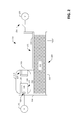
- FIG. 1 is a cross-sectional view of an exemplary short pulse neutron generator.
- FIG. 2 is a cross-sectional view of another exemplary short pulse neutron generator.
- FIG. 3 is an isometric view of an exemplary short pulse neutron generator.
- FIG. 4 is another isometric view of an exemplary short pulse neutron generator.
- FIG. 5 is an isometric view of an exemplary vacuum chamber included in an exemplary short pulse neutron generator.
- FIG. 6 is a flow diagram that illustrates an exemplary methodology for forming a short pulse neutron generator.
- FIG. 7 is flow diagram that illustrates an exemplary methodology for operating a short pulse neutron generator.
- the term “or” is intended to mean an inclusive “or” rather than an exclusive “or.” That is, unless specified otherwise, or clear from the context, the phrase “X employs A or B” is intended to mean any of the natural inclusive permutations. That is, the phrase “X employs A or B” is satisfied by any of the following instances: X employs A; X employs B; or X employs both A and B.
- the articles “a” and “an” as used in this application and the appended claims should generally be construed to mean “one or more” unless specified otherwise or clear from the context to be directed to a singular form.
- An exemplary short pulse neutron generator described herein can output a neutron pulse having a pulse length of between one nanosecond and 100 nanoseconds. Furthermore, an exemplary short pulse neutron generator described herein can generate neutron pulses relatively rapidly, such as with a frequency of between 1 Hz and 2440 Hz (or higher). The exemplary short pulse neutron generators described herein have a variety of applications, including radiography and material identification. As a length (in time) of the pulse of neutrons generated by the exemplary short pulse neutron generator is relatively short, harmful effects associated with conventional neutron generators may be avoided.
- the neutron generator 100 comprises a Blumlein structure.
- the Blumlein structure includes a first conductive plate 102 and a second conductive plate 104 . At least a portion of the first conductive plate 102 and the second conductive plate 104 can be coplanar with one another, with optional orthogonal extensions therefrom.
- the first conductive plate 104 and the second conductive plate 102 are positioned such that a gap 106 separates the first conductive plate 102 from the second conductive plate 104 .
- At least one of a resistor or inductor 108 with relatively high impedance can be placed between the first conductive plate 102 and the second conductive plate 104 .
- Recharge rate of the second conductive plate 104 can be based upon the value of the impedance of the at least one of the resistor or inductor 108 .
- the Blumlein structure further includes a third conductive plate 110 that is electrically grounded.
- the third conductive plate 110 may be positioned in parallel with the first conductive plate 102 and the second conductive plate 104 , wherein a dielectric material 112 separates the first conductive plate 102 from the third conductive plate 110 , and further optionally separates the second conductive plate 104 from the third conductive plate 110 .
- the Blumlein structure can further comprise a switch 114 that is configured to connect and disconnect the second conductive plate 104 to and from the third conductive plate 110 .
- the switch 114 can be a spark gap.
- the first conductive plate 102 , the second conductive plate 104 , and the third conductive plate 110 can be composed of any suitable conductive material, including copper, steel, titanium, or the like.
- the dielectric material 112 may also be any suitable dielectric material, including porcelain, glass, a plastic, etc.
- the neutron generator 100 additionally includes a vacuum chamber 116 positioned in the gap 106 between the first conductive plate 102 and the second conductive plate 104 .
- a first electrode 118 is included in the vacuum chamber 116 and extends from the first conductive plate 102 .
- the first electrode 118 includes a target surface 120 that can be loaded with tritium and/or deuterium.
- a second electrode 122 is also included in the vacuum chamber 116 and extends from the second conductive plate 104 .
- the second electrode 122 comprises a face 124 , wherein the face forms a cavity 126 , the face 124 positioned between the cavity 126 and the target surface 120 .
- the face 124 of the second electrode 122 opposes the target surface 120 of the first electrode, the face 124 of the second electrode 122 separated from the target surface 120 of the first electrode 118 by an accelerating gap.
- the accelerating gap can be between 0.1 centimeter and 2 centimeters.
- the face 124 can comprise a plurality of apertures extending therethrough.
- An ion generator 128 can be positioned to emit ions into the cavity 126 . Accordingly, as shown, the ion generator 128 can be positioned in the cavity 126 . In another exemplary embodiment, the ion generator 128 can be external to the vacuum chamber 116 , but can be configured to emit ions into the cavity 126 .
- a first voltage source 130 which is configured to output a relatively high voltage (e.g., between 50 kV and 50 MV), is electrically connected to the first conductive plate 102 .
- a second voltage source 132 is electrically connected to the ion generator 128 and is configured to drive the ion generator 128 , thereby causing the ion generator 128 to generate ions.
- the switch 114 is opened, disconnecting the first voltage source 130 , the first conductive plate 102 , the at least one of the resistor or the inductor 108 , and the second conductive plate 104 from the third conductive plate 110 (and thus from ground).
- the first voltage source 130 outputs a relatively high voltage, creating a short circuit between the first conductive plate 102 and the second conductive plate 104 , resulting in the first conductive plate 102 and the second conductive plate 104 retaining an electrical charge (e.g., having an equivalent voltage).
- the second voltage source 132 is then configured to drive the ion generator 128 , causing the ion generator 128 to populate the cavity 126 with ions.
- the ions in the cavity 126 are not attracted to either of the first electrode 118 or the second electrode 122 .
- Population of the cavity 126 with ions while voltage of the first electrode 118 and the second electrode 122 are approximately equivalent can be referred to as “pre-filling” the cavity 126 .
- the first voltage source 130 ceases to output the relatively high voltage, and the switch 114 is closed. Responsive to the switch closing, voltage of the second conductive plate 104 (and thus the second electrode 122 ) rapidly drops, while the voltage of the first conductive plate 102 (and thus the first electrode 118 ) remains relatively high.
- the ions in the cavity 126 are thus attracted to the first electrode 118 , and ions proximate to the face 124 exit the cavity 126 by way of the apertures and are accelerated over the accelerating gap towards the target surface 120 of the first electrode 118 .
- Such ions impact the tritium or deuterium in the target surface 120 , forming neutrons that are isotropically emitted from the vacuum chamber 116 .
- the first conductive plate 102 discharges via the ions accelerated in the gap between the first electrode 118 and the second electrode 122 , wherein the current of accelerated ions can be several milli-amperes (mA) to thousands of amperes (kA), as determined by a production strength of the ion generator 128 , size of the cavity 126 , and ultimately a number of neutrons desired by an operator of the neutron generator 100 .
- the discharge time duration is controlled by the dimensions of the first conductive plate 102 , the second conductive plate 104 , and the third conductive plate 110 in an axis perpendicular to the first electrode 118 and the second electrode 122 (e.g., along the x-axis).
- the current magnitude is controlled by the dimensions of the first conductive plate 102 , the second conductive plate 104 , and the third conductive plate 110 in an axis parallel to the first electrode 118 and the second electrode 122 (e.g., along the z-axis).
- the switch 114 can be opened and the first voltage source 130 can be configured to output the relatively high voltage, thereby charging the first conductive plate 102 and the second conductive plate 104 .
- This process can repeat relatively rapidly, such as on the order of 60 Hz, 120 Hz, 240 Hz, or 2400 Hz.
- the switch 114 may be a spark gap.
- the switch 114 can be or include a Silicon-controlled rectifier (SCR), a high-power MOS-FET-based solid state switching arrangement, etc.
- SCR Silicon-controlled rectifier
- MOS-FET-based solid state switching arrangement etc.
- another voltage source can drive, or trigger, the spark gap or solid state-based switch, causing a short to occur between the second conductive plate 104 and the third conductive plate 110 , for example, when the spark gap is fired.
- dimensions of portions of the neutron generator 100 can be selected based upon desired duration of a neutron pulse, a number of neutrons desirably generated by the neutron generator 100 , etc. For instance, as length of the first conductive plate 102 and/or the second conductive plate 104 increases, a duration of a voltage pulse at the first electrode 118 increases. Further, distance between the target surface 120 and the face 124 can be selected based upon a desired discharge rate of the first conductive plate 102 . Moreover, a number of ion generators, position of ion generators, size of the cavity 126 , size of the target surface 120 , etc. can be selected based upon a volume of neutrons desirably generated.
- the target surface 120 of the first electrode 118 and the face 124 of the second electrode 122 are shown as being planar in nature, it is to be understood that the target surface 120 and/or the face 124 may have a three-dimensional curved profile, such as a three-dimensional elliptical surface, a surface with a Rogowsky profile, or a surface with a Chen profile.
- the face 124 has been described as comprising apertures extending therethrough, it is to be understood that the face 124 can be designed with a curved profile or “L” shape in such a manner that ions can escape the cavity 126 .
- the cavity 126 may be only partially enclosed.
- the first voltage source 130 can be an AC voltage source that continuously provides voltage to the first conductive plate 102 .
- the second voltage source 132 is timed relative to the first voltage source to populate the cavity 126 when the first conductive plate 102 is nearing completion of discharge and beginning to re-charge.
- the switch 114 is timed with a frequency that corresponds to the frequency of the first voltage source 130 .
- the target surface 120 can form a second cavity 134 , and a second ion generator (not shown) can be positioned to populate the second cavity 134 with ions.
- the face 124 of the second electrode can be loaded with deuterium and/or tritium, and the relative polarities of the first electrode 118 and second electrode 122 can alternate. Accordingly, ions are accelerated in both directions in the accelerating gap, depending upon the relative polarities of the first electrode 118 and the second electrode 122 .
- the discharge chamber 116 can optionally include polarized rods that are positioned relative to the ion generator 128 and the face 124 of the second electrode 122 to prevent secondary electron emissions.
- polarized rods can extend along the length of the cavity 126 (e.g., along the x-axis), directing the ions towards the face 124 and the apertures therethrough.
- the ion source 128 can be any suitable ion source.
- the ion source 128 can be a relatively high current surface discharge ion source that is capable of de-sorbing loaded deuterium and ionizing such deuterium at approximately the same time.
- the ion source can comprise a thin film of titanium, scandium, or other suitable metal that includes deuterium loaded thereon.
- the ion source 128 may comprise two opposing electrodes, an array of series electrodes, or an array of parallel electrodes.
- An exemplary ion source can be composed of two opposing electrodes made of tritium, erbium, or scandium, loaded with deuterium, such that deuterium gas is released as the temperature rises, which occurs as current flows. That is, ions are formed by the electron flow from the opposite electrode.
- the exemplary neutron generator 200 comprises a first conductive plate 202 and a second conductive plate 204 .
- the first conductive plate 202 includes a first portion 206 that extends laterally in a first plane and a second portion 208 that extends orthogonally from the first portion 206 at an end of the first portion 206 .
- the second conductive plate 204 comprises a first portion 210 that extends laterally in parallel with the first portion 206 of the first conductive plate 202 and beyond the second portion 208 of the first conductive plate 202 .
- the second conductive plate 204 also includes a second portion 214 that extends orthogonally from the first portion 210 of the second conductive plate 204 at an end thereof, and in parallel with the second portion 208 of the first conductive plate 202 .
- a gap 216 is formed between the second portion 208 of the first conductive plate 202 and the second portion 214 of the second conductive plate 204 .
- the vacuum chamber 116 can be positioned in the gap 216 and can comprise the first electrode 118 having the target surface 120 , the second electrode 122 having the face 124 that forms the cavity 126 , and the ion source 128 , as described above.
- a switch 220 such as a spark gap, electrically connects and disconnects the first voltage source 130 to and from the first conductive plate 202 .
- a dielectric material 222 is positioned in a gap between the first portion 206 of the first conductive plate 202 and the first portion 210 of the second conductive plate 204 .
- the switch 220 can be opened, such that both the first conductive plate 202 and the second conductive plate 204 are uncharged.
- the second voltage source 132 drives the ion generator 128 , causing the ion generator 128 to populate the cavity 126 with ions.
- the switch 220 is closed, causing the first conductive plate 202 to be charged for a relatively short amount of time. Ions in the pre-filled cavity 126 can escape, for example, through apertures of the face 124 and impact tritium or deuterium loaded into the target surface 120 of the second electrode 118 .
- the switch 220 may then be opened, causing the first conductive plate 202 to discharge by way of the ions accelerated from the second electrode 118 to the first electrode 122 in the accelerating gap.
- the target surface 120 and the face 124 of the second electrode 122 can have a three-dimensional curved profile.
- the target surface 120 and the surface of the face 124 may have a three-dimensional elliptical shape.
- the ion source 128 can be positioned in the cavity formed by the elliptical shape of the face 124 of the first electrode 122 .
- the switch 114 is shown as being a spark gap, that, when fired, creates a short circuit between the second conductive plate 104 and the third conductive plate 110 .
- FIG. 4 illustrates another isometric view of the exemplary neutron generator 100 .
- the ion source 128 is shown as comprising a plurality of ion generators, which are arranged in matrix form to populate the cavity 126 formed by the curved surface of the face 124 of the second electrode 122 with ions.
- the face 124 includes a plurality of apertures 502 extending therethrough, such that ions proximate to the face 124 in the cavity 126 can escape the cavity 126 and be accelerated across the accelerating gap, thereby impacting the target surface 120 of the first electrode 118 .
- the ions impact the deuterium or tritium on the target surface 120 , neutrons are generated and escape isotropically from the vacuum chamber 116 .
- FIGS. 6-7 illustrate exemplary methodologies relating to short pulse neutron generation. While the methodologies are shown and described as being a series of acts that are performed in a sequence, it is to be understood and appreciated that the methodologies are not limited by the order of the sequence. For example, some acts can occur in a different order than what is described herein. In addition, an act can occur concurrently with another act. Further, in some instances, not all acts may be required to implement a methodology described herein.
- the methodology 600 starts at 602 , and at 604 a first conductive plate, a second conductive plate, a third conductive plate, a dielectric material, a switch, and at least one of a resistor and/or inductor are positioned relative to one another to form a Blumlein structure.
- the first conductive plate can be positioned relative to the second conductive plate such that the first conductive plate and the second conductive plate are coplanar and separated by a gap.
- the third conductive plate can be positioned in parallel with the first conductive plate and the second conductive plate, such that the third conductive plate is separated by a gap from the first conductive plate, and is further separated by a gap from the second conductive plate.
- the dielectric material can fill at least the gap between the first conductive plate and the third conductive plate.
- forming the Blumlein structure can include positioning the at least one of the resistor or the inductor, such that the at least one of the resistor or the inductor is coupled to the first conductive plate and the second conductive plate.
- an ion generator is positioned in the gap between the first conductive plate and the second conductive plate in the Blumlein structure.
- the methodology 600 completes at 608 .
- the methodology 700 starts at 702 , and at 704 an initiation conductive plate and a discharge conductive plate are charged through utilization of a relatively high voltage source (e.g., 50 kV, 1 MV, 50 MV, etc.).
- a relatively high voltage source e.g., 50 kV, 1 MV, 50 MV, etc.
- an ion generator is caused to populate (pre-fill) a cavity with ions, the cavity positioned in a vacuum chamber, the vacuum chamber positioned in a gap of a Blumlein structure.
- the initiation conductive plate is electrically connected to ground, leaving the discharge conductive plate with an electric charge that attracts ions in the cavity.
- Such ions can be attracted to a target surface loaded with deuterium or tritium, thereby producing neutrons.
- the initiation conductive plate is disconnected from ground.
- the methodology 700 then returns to 704 , where the methodology 700 can repeat indefinitely.
Abstract
Description
Claims (20)
Priority Applications (2)
| Application Number | Priority Date | Filing Date | Title |
|---|---|---|---|
| US14/016,609 US9408286B1 (en) | 2013-09-03 | 2013-09-03 | Short pulse neutron generator |
| US15/190,035 US10278276B2 (en) | 2013-09-03 | 2016-06-22 | Short pulse neutron generator |
Applications Claiming Priority (1)
| Application Number | Priority Date | Filing Date | Title |
|---|---|---|---|
| US14/016,609 US9408286B1 (en) | 2013-09-03 | 2013-09-03 | Short pulse neutron generator |
Related Child Applications (1)
| Application Number | Title | Priority Date | Filing Date |
|---|---|---|---|
| US15/190,035 Continuation US10278276B2 (en) | 2013-09-03 | 2016-06-22 | Short pulse neutron generator |
Publications (1)
| Publication Number | Publication Date |
|---|---|
| US9408286B1 true US9408286B1 (en) | 2016-08-02 |
Family
ID=56507350
Family Applications (2)
| Application Number | Title | Priority Date | Filing Date |
|---|---|---|---|
| US14/016,609 Active 2034-01-08 US9408286B1 (en) | 2013-09-03 | 2013-09-03 | Short pulse neutron generator |
| US15/190,035 Active 2034-07-28 US10278276B2 (en) | 2013-09-03 | 2016-06-22 | Short pulse neutron generator |
Family Applications After (1)
| Application Number | Title | Priority Date | Filing Date |
|---|---|---|---|
| US15/190,035 Active 2034-07-28 US10278276B2 (en) | 2013-09-03 | 2016-06-22 | Short pulse neutron generator |
Country Status (1)
| Country | Link |
|---|---|
| US (2) | US9408286B1 (en) |
Cited By (1)
| Publication number | Priority date | Publication date | Assignee | Title |
|---|---|---|---|---|
| US11534626B2 (en) * | 2021-03-31 | 2022-12-27 | Varian Medical Systems Particle Therapy Gmbh & Co. Kg | Asymmetric dual-mode ionization systems and methods |
Citations (9)
| Publication number | Priority date | Publication date | Assignee | Title |
|---|---|---|---|---|
| US4223279A (en) | 1977-07-18 | 1980-09-16 | Mathematical Sciences Northwest, Inc. | Pulsed electric discharge laser utilizing water dielectric blumlein transmission line |
| US4298804A (en) * | 1978-10-13 | 1981-11-03 | U.S. Philips Corporation | Neutron generator having a target |
| US20050220244A1 (en) | 2001-03-16 | 2005-10-06 | The Regents Of The University Of California | Cylindrical neutron generator |
| US20100032580A1 (en) * | 2006-10-24 | 2010-02-11 | Lawrence Livermore National Security, Llc | Compact Accelerator For Medical Therapy |
| US20120146553A1 (en) | 2010-12-08 | 2012-06-14 | Vladimir Andreevich Joshkin | Blumlein Assembly with Solid State Switch |
| US20120213319A1 (en) | 2009-08-14 | 2012-08-23 | The Regents Of The University Of California | Fast Pulsed Neutron Generator |
| US20130048847A1 (en) | 2011-08-26 | 2013-02-28 | Baker Hughes Incorporated | Targetless Pulsed Neutron Generator Using Beam-Beam Interaction |
| US20130170592A1 (en) * | 2011-12-28 | 2013-07-04 | Zilu Zhou | Device and method for ion generation |
| US20130180780A1 (en) | 2011-12-22 | 2013-07-18 | Schlumberger Technology Corporation | Pulsed Neutron Generator Tube Design Which Extends The Lifetime Of A Cathode |
-
2013
- 2013-09-03 US US14/016,609 patent/US9408286B1/en active Active
-
2016
- 2016-06-22 US US15/190,035 patent/US10278276B2/en active Active
Patent Citations (9)
| Publication number | Priority date | Publication date | Assignee | Title |
|---|---|---|---|---|
| US4223279A (en) | 1977-07-18 | 1980-09-16 | Mathematical Sciences Northwest, Inc. | Pulsed electric discharge laser utilizing water dielectric blumlein transmission line |
| US4298804A (en) * | 1978-10-13 | 1981-11-03 | U.S. Philips Corporation | Neutron generator having a target |
| US20050220244A1 (en) | 2001-03-16 | 2005-10-06 | The Regents Of The University Of California | Cylindrical neutron generator |
| US20100032580A1 (en) * | 2006-10-24 | 2010-02-11 | Lawrence Livermore National Security, Llc | Compact Accelerator For Medical Therapy |
| US20120213319A1 (en) | 2009-08-14 | 2012-08-23 | The Regents Of The University Of California | Fast Pulsed Neutron Generator |
| US20120146553A1 (en) | 2010-12-08 | 2012-06-14 | Vladimir Andreevich Joshkin | Blumlein Assembly with Solid State Switch |
| US20130048847A1 (en) | 2011-08-26 | 2013-02-28 | Baker Hughes Incorporated | Targetless Pulsed Neutron Generator Using Beam-Beam Interaction |
| US20130180780A1 (en) | 2011-12-22 | 2013-07-18 | Schlumberger Technology Corporation | Pulsed Neutron Generator Tube Design Which Extends The Lifetime Of A Cathode |
| US20130170592A1 (en) * | 2011-12-28 | 2013-07-04 | Zilu Zhou | Device and method for ion generation |
Non-Patent Citations (1)
| Title |
|---|
| Rebersek, et al., "Blumlein Configuration for High-Repetition-Rate Pulse Generation of Variable Duration and Polarity Using Synchronized Switch Control", IEEE Transactions on Biomedical Engineering, vol. 56, No. 11, Nov. 2009, pp. 2642-2648. |
Cited By (3)
| Publication number | Priority date | Publication date | Assignee | Title |
|---|---|---|---|---|
| US11534626B2 (en) * | 2021-03-31 | 2022-12-27 | Varian Medical Systems Particle Therapy Gmbh & Co. Kg | Asymmetric dual-mode ionization systems and methods |
| US20230125731A1 (en) * | 2021-03-31 | 2023-04-27 | Varian Medical Systems Particle Therapy Gmbh & Co. Kg | Asymmetric dual-mode ionization systems and methods |
| US11944845B2 (en) * | 2021-03-31 | 2024-04-02 | Varian Medical Systems Particle Therapy Gmbh & Co. Kg | Asymmetric dual-mode ionization systems and methods |
Also Published As
| Publication number | Publication date |
|---|---|
| US20160302297A1 (en) | 2016-10-13 |
| US10278276B2 (en) | 2019-04-30 |
Similar Documents
| Publication | Publication Date | Title |
|---|---|---|
| EP2158796B1 (en) | Beam transport system and method for linear accelerators | |
| Savage et al. | Status of the Z pulsed power driver | |
| KR20080059395A (en) | Sequentially pulsed traveling wave accelerator | |
| Rose et al. | Plasma evolution and dynamics in high-power vacuum-transmission-line post-hole convolutes | |
| Sack et al. | Triggered Marx generators for the industrial-scale electroporation of sugar beets | |
| Rej et al. | Microsecond pulse width, intense, light‐ion beam accelerator | |
| US10278276B2 (en) | Short pulse neutron generator | |
| Kandaurov et al. | Submillisecond electron beam for plasma heating in multi-mirror trap GOL-3 | |
| Kovalchuk et al. | Electron-beam accelerator for pumping of a Xe2 lamp | |
| RU187270U1 (en) | PULSE NEUTRON GENERATOR | |
| Bochkov et al. | Development of high-power gas discharge and electronic vacuum devices for pulsed electrophysic. Current status and prospects | |
| Pal | Particle-in-cell simulation study of PCE-gun for different hollow cathode aperture sizes | |
| Elizondo-Decanini | Short pulse neutron generator | |
| CN1972553A (en) | An ion trap based on superconducting radio frequency accelerating electron | |
| Mazarakis et al. | Linear transformer driver (LTD) development at Sandia National Laboratory | |
| Chen | Compact, repetitive Marx generator and HPM generation with the vircator | |
| RU2448387C2 (en) | Method to produce high-charge ion beam | |
| Su et al. | Experiment and applications of SOS-based pulsed power. | |
| Wang | A Tesla-Blumlein PFL-bipolar pulsed power generator | |
| Xu et al. | Dark current study of a standing wave disk-loaded waveguide structure at 17 GHz | |
| Leckbee et al. | Load line evaluation of a 1-MV linear transformer driver (LTD) | |
| Bukharov et al. | Investigation program on plasma current open switches on" EMIR" project | |
| Hsu et al. | A high‐power electron beam source based on the superemissive cathode | |
| Liu et al. | Injection and induction acceleration of Ar3+ in the KEK digital accelerator | |
| Lamba et al. | Design and development of a high current pseudospark switch for pulse power applications |
Legal Events
| Date | Code | Title | Description |
|---|---|---|---|
| AS | Assignment |
Owner name: U.S. DEPARTMENT OF ENERGY, DISTRICT OF COLUMBIA Free format text: CONFIRMATORY LICENSE;ASSIGNOR:SANDIA CORPORATION;REEL/FRAME:031246/0855 Effective date: 20130905 |
|
| AS | Assignment |
Owner name: SANDIA CORPORATION, NEW MEXICO Free format text: ASSIGNMENT OF ASSIGNORS INTEREST;ASSIGNOR:ELIZONDO-DECANINI, JUAN M.;REEL/FRAME:031272/0608 Effective date: 20130903 |
|
| AS | Assignment |
Owner name: U.S. DEPARTMENT OF ENERGY, DISTRICT OF COLUMBIA Free format text: CONFIRMATORY LICENSE;ASSIGNOR:SANDIA CORPORATION;REEL/FRAME:031796/0195 Effective date: 20130905 |
|
| STCF | Information on status: patent grant |
Free format text: PATENTED CASE |
|
| AS | Assignment |
Owner name: NATIONAL TECHNOLOGY & ENGINEERING SOLUTIONS OF SAN Free format text: CHANGE OF NAME;ASSIGNOR:SANDIA CORPORATION;REEL/FRAME:047052/0192 Effective date: 20170501 |
|
| MAFP | Maintenance fee payment |
Free format text: PAYMENT OF MAINTENANCE FEE, 4TH YEAR, LARGE ENTITY (ORIGINAL EVENT CODE: M1551); ENTITY STATUS OF PATENT OWNER: LARGE ENTITY Year of fee payment: 4 |
|
| MAFP | Maintenance fee payment |
Free format text: PAYMENT OF MAINTENANCE FEE, 8TH YEAR, LARGE ENTITY (ORIGINAL EVENT CODE: M1552); ENTITY STATUS OF PATENT OWNER: LARGE ENTITY Year of fee payment: 8 |