US9405626B1 - At risk data caching (ARDC) - Google Patents
At risk data caching (ARDC) Download PDFInfo
- Publication number
- US9405626B1 US9405626B1 US14/137,575 US201314137575A US9405626B1 US 9405626 B1 US9405626 B1 US 9405626B1 US 201314137575 A US201314137575 A US 201314137575A US 9405626 B1 US9405626 B1 US 9405626B1
- Authority
- US
- United States
- Prior art keywords
- data
- parity
- stripe
- data portion
- cache memory
- Prior art date
- Legal status (The legal status is an assumption and is not a legal conclusion. Google has not performed a legal analysis and makes no representation as to the accuracy of the status listed.)
- Active, expires
Links
- 230000015654 memory Effects 0.000 claims abstract description 52
- 238000000034 method Methods 0.000 claims abstract description 45
- 238000004590 computer program Methods 0.000 claims abstract description 18
- 230000008569 process Effects 0.000 description 33
- 238000010586 diagram Methods 0.000 description 10
- 230000006870 function Effects 0.000 description 10
- 230000003287 optical effect Effects 0.000 description 6
- 238000004891 communication Methods 0.000 description 3
- 230000005055 memory storage Effects 0.000 description 3
- 238000012986 modification Methods 0.000 description 3
- 230000004048 modification Effects 0.000 description 3
- 230000001413 cellular effect Effects 0.000 description 2
- 230000003247 decreasing effect Effects 0.000 description 2
- 239000000463 material Substances 0.000 description 2
- 239000013307 optical fiber Substances 0.000 description 2
- 238000003491 array Methods 0.000 description 1
- 230000005540 biological transmission Effects 0.000 description 1
- 230000008859 change Effects 0.000 description 1
- 239000000835 fiber Substances 0.000 description 1
- 230000007257 malfunction Effects 0.000 description 1
- 238000004519 manufacturing process Methods 0.000 description 1
- 230000000644 propagated effect Effects 0.000 description 1
- 230000008929 regeneration Effects 0.000 description 1
- 238000011069 regeneration method Methods 0.000 description 1
- 239000004065 semiconductor Substances 0.000 description 1
Images


Classifications
-
- G—PHYSICS
- G06—COMPUTING; CALCULATING OR COUNTING
- G06F—ELECTRIC DIGITAL DATA PROCESSING
- G06F11/00—Error detection; Error correction; Monitoring
- G06F11/07—Responding to the occurrence of a fault, e.g. fault tolerance
- G06F11/08—Error detection or correction by redundancy in data representation, e.g. by using checking codes
- G06F11/10—Adding special bits or symbols to the coded information, e.g. parity check, casting out 9's or 11's
- G06F11/1076—Parity data used in redundant arrays of independent storages, e.g. in RAID systems
- G06F11/1088—Reconstruction on already foreseen single or plurality of spare disks
-
- G—PHYSICS
- G06—COMPUTING; CALCULATING OR COUNTING
- G06F—ELECTRIC DIGITAL DATA PROCESSING
- G06F11/00—Error detection; Error correction; Monitoring
- G06F11/07—Responding to the occurrence of a fault, e.g. fault tolerance
- G06F11/08—Error detection or correction by redundancy in data representation, e.g. by using checking codes
- G06F11/10—Adding special bits or symbols to the coded information, e.g. parity check, casting out 9's or 11's
- G06F11/1076—Parity data used in redundant arrays of independent storages, e.g. in RAID systems
- G06F11/1084—Degraded mode, e.g. caused by single or multiple storage removals or disk failures
Definitions
- This disclosure relates to storage systems and, more particularly, to systems and methods for safeguarding data.
- a computer-implemented method includes sensing the occurrence of an degraded condition within a data stripe of a RAID array.
- the data strip includes one or more valid data portions, one invalid data portion, and a parity portion.
- a request to write updated content to a target data portion within the data stripe is received, wherein the target data portion is one of the valid data portions.
- the valid data portions and the parity portion are read from the data stripe.
- the invalid data portion is reconstructed using the valid data portions and the parity portion, thus generating a reconstructed data portion.
- the reconstructed data portion is stored within a mirrored cache memory system.
- the parity portion is updated to define the updated content, thus defining an updated parity portion.
- the updated parity portion is written to the data stripe and the updated content is written to the target data portion within the data stripe.
- the data stripe may be restored using: the updated content to be written to the target data portion; the reconstructed data portion stored within the mirrored cache memory system; and the one or more valid data portions that are not the target data portion.
- the mirrored cache memory system may be mirrored between a plurality of storage processors.
- Reconstructing the invalid data portion may include performing an XOR operation on the combination of the valid data portions and the parity portion.
- Updating the parity portion to define the updated content may include processing the parity portion to extract old content currently in the target data portion and add updated content to the target data portion.
- the degraded condition may be the result of one or more of: a drive failure and a media error.
- the RAID array may be one of a RAID 3 array, RAID 5 array and a RAID 6 array.
- a computer program product resides on a computer readable medium and has a plurality of instructions stored on it. When executed by a processor, the instructions cause the processor to perform operations including sensing the occurrence of an degraded condition within a data stripe of a RAID array.
- the data strip includes one or more valid data portions, one invalid data portion, and a parity portion.
- a request to write updated content to a target data portion within the data stripe is received, wherein the target data portion is one of the valid data portions.
- the valid data portions and the parity portion are read from the data stripe.
- the invalid data portion is reconstructed using the valid data portions and the parity portion, thus generating a reconstructed data portion.
- the reconstructed data portion is stored within a mirrored cache memory system.
- the parity portion is updated to define the updated content, thus defining an updated parity portion.
- the updated parity portion is written to the data stripe and the updated content is written to the target data portion within the data stripe.
- the data stripe may be restored using: the updated content to be written to the target data portion; the reconstructed data portion stored within the mirrored cache memory system; and the one or more valid data portions that are not the target data portion.
- the mirrored cache memory system may be mirrored between a plurality of storage processors.
- Reconstructing the invalid data portion may include performing an XOR operation on the combination of the valid data portions and the parity portion.
- Updating the parity portion to define the updated content may include processing the parity portion to extract old content currently in the target data portion and add updated content to the target data portion.
- the degraded condition may be the result of one or more of: a drive failure and a media error.
- the RAID array may be one of a RAID 3 array, RAID 5 array and a RAID 6 array.
- a computing system including a processor and memory is configured to perform operations including sensing the occurrence of an degraded condition within a data stripe of a RAID array.
- the data strip includes one or more valid data portions, one invalid data portion, and a parity portion.
- a request to write updated content to a target data portion within the data stripe is received, wherein the target data portion is one of the valid data portions.
- the valid data portions and the parity portion are read from the data stripe.
- the invalid data portion is reconstructed using the valid data portions and the parity portion, thus generating a reconstructed data portion.
- the reconstructed data portion is stored within a mirrored cache memory system.
- the parity portion is updated to define the updated content, thus defining an updated parity portion.
- the updated parity portion is written to the data stripe and the updated content is written to the target data portion within the data stripe.
- the data stripe may be restored using: the updated content to be written to the target data portion; the reconstructed data portion stored within the mirrored cache memory system; and the one or more valid data portions that are not the target data portion.
- the mirrored cache memory system may be mirrored between a plurality of storage processors.
- Reconstructing the invalid data portion may include performing an XOR operation on the combination of the valid data portions and the parity portion.
- Updating the parity portion to define the updated content may include processing the parity portion to extract old content currently in the target data portion and add updated content to the target data portion.
- the degraded condition may be the result of one or more of: a drive failure and a media error.
- the RAID array may be one of a RAID 3 array, RAID 5 array and a RAID 6 array.
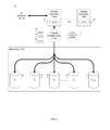
- FIG. 1 is a diagrammatic view of a storage system and a storage management process coupled to a distributed computing network;
- FIG. 2 is a diagrammatic view of the storage system of FIG. 1 ;
- FIG. 3 is a diagrammatic view of the data array of FIG. 2 ;
- FIG. 4 is a flow chart of one implementation of the storage management process of FIG. 1 .
- storage management process 10 may reside on and may be executed by storage system 12 , which may be connected to network 14 (e.g., the Internet or a local area network).
- network 14 e.g., the Internet or a local area network.
- Examples of storage system 12 may include, but are not limited to: a Network Attached Storage (NAS) system, a Storage Area Network (SAN), a personal computer with a memory system, a server computer with a memory system, and a cloud-based device with a memory system.
- NAS Network Attached Storage
- SAN Storage Area Network
- a SAN may include one or more of a personal computer, a server computer, a series of server computers, a mini computer, a mainframe computer, a RAID device and a NAS system.
- the various components of storage system 12 may execute one or more operating systems, examples of which may include but are not limited to: Microsoft Windows 2003 ServerTM; Redhat LinuxTM, Unix, or a custom operating system, for example.
- Storage device 16 may include but is not limited to: a hard disk drive; a tape drive; an optical drive; a RAID device; a random access memory (RAM); a read-only memory (ROM); and all forms of flash memory storage devices.
- Network 14 may be connected to one or more secondary networks (e.g., network 18 ), examples of which may include but are not limited to: a local area network; a wide area network; or an intranet, for example.
- secondary networks e.g., network 18
- networks may include but are not limited to: a local area network; a wide area network; or an intranet, for example.
- IO requests may be sent from client applications 22 , 24 , 26 , 28 to storage system 12 .
- Examples of IO request 20 may include but are not limited to data write requests (i.e. a request that content be written to storage system 12 ) and data read requests (i.e. a request that content be read from storage system 12 ).
- the instruction sets and subroutines of client applications 22 , 24 , 26 , 28 which may be stored on storage devices 30 , 32 , 34 , 36 (respectively) coupled to client electronic devices 38 , 40 , 42 , 44 (respectively), may be executed by one or more processors (not shown) and one or more memory architectures (not shown) incorporated into client electronic devices 38 , 40 , 42 , 44 (respectively).
- Storage devices 30 , 32 , 34 , 36 may include but are not limited to: hard disk drives; tape drives; optical drives; RAID devices; random access memories (RAM); read-only memories (ROM), and all forms of flash memory storage devices.
- client electronic devices 38 , 40 , 42 , 44 may include, but are not limited to, personal computer 38 , laptop computer 40 , personal digital assistant 42 , notebook computer 44 , a server (not shown), a data-enabled, cellular telephone (not shown), and a dedicated network device (not shown).
- Users 46 , 48 , 50 , 52 may access storage system 12 directly through network 14 or through secondary network 18 . Further, storage system 12 may be connected to network 14 through secondary network 18 , as illustrated with link line 54 .
- the various client electronic devices may be directly or indirectly coupled to network 14 (or network 18 ).
- personal computer 38 is shown directly coupled to network 14 via a hardwired network connection.
- notebook computer 44 is shown directly coupled to network 18 via a hardwired network connection.
- Laptop computer 40 is shown wirelessly coupled to network 14 via wireless communication channel 56 established between laptop computer 40 and wireless access point (i.e., WAP) 58 , which is shown directly coupled to network 14 .
- WAP 58 may be, for example, an IEEE 802.11a, 802.11b, 802.11g, 802.11n, Wi-Fi, and/or Bluetooth device that is capable of establishing wireless communication channel 56 between laptop computer 40 and WAP 58 .
- Personal digital assistant 42 is shown wirelessly coupled to network 14 via wireless communication channel 60 established between personal digital assistant 42 and cellular network/bridge 62 , which is shown directly coupled to network 14 .
- Client electronic devices 38 , 40 , 42 , 44 may each execute an operating system, examples of which may include but are not limited to Microsoft WindowsTM, Apple MacintoshTM, Redhat LinuxTM, or a custom operating system.
- storage system 12 will be described as being a network-based storage system that includes a plurality of electro-mechanical backend storage devices.
- this is for illustrative purposes only and is not intended to be a limitation of this disclosure, as other configurations are possible and are considered to be within the scope of this disclosure.
- storage system 12 may include storage processor 100 and a plurality of storage targets T 1-n (e.g. storage targets 102 , 104 , 106 , 108 ).
- Storage targets 102 , 104 , 106 , 108 may be configured to provide various levels of performance and/or high availability.
- one or more of storage targets 102 , 104 , 106 , 108 may be configured as a RAID 0 array, in which data is striped across storage targets. By striping data across a plurality of storage targets, improved performance may be realized. However, RAID 0 arrays do not provide a level of high availability.
- one or more of storage targets 102 , 104 , 106 , 108 may be configured as a RAID 1 array, in which data is mirrored between storage targets. By mirroring data between storage targets, a level of high availability is achieved as multiple copies of the data are stored within storage system 12 .
- storage targets 102 , 104 , 106 , 108 are discussed above as being configured in a RAID 0 or RAID 1 array, this is for illustrative purposes only and is not intended to be a limitation of this disclosure, as other configurations are possible.
- storage targets 102 , 104 , 106 , 108 may be configured as a RAID 3, RAID 4, RAID 5 or RAID 6 array.
- storage system 12 is shown to include four storage targets (e.g. storage targets 102 , 104 , 106 , 108 ), this is for illustrative purposes only and is not intended to be a limitation of this disclosure. Specifically, the actual number of storage targets may be increased or decreased depending upon e.g. the level of redundancy/performance/capacity required.
- Storage system 12 may also include one or more coded targets 110 .
- a coded target may be used to store coded data that may allow for the regeneration of data lost/corrupted on one or more of storage targets 102 , 104 , 106 , 108 .
- An example of such a coded target may include but is not limited to a hard disk drive that is used to store parity data within a RAID array.
- storage system 12 is shown to include one coded target (e.g., coded target 110 ), this is for illustrative purposes only and is not intended to be a limitation of this disclosure. Specifically, the actual number of coded targets may be increased or decreased depending upon e.g. the level of redundancy/performance/capacity required.
- Examples of storage targets 102 , 104 , 106 , 108 and coded target 110 may include one or more electro-mechanical hard disk drives and/or solid-state/Flash devices, wherein a combination of storage targets 102 , 104 , 106 , 108 and coded target 110 and processing/control systems (not shown) may form data array 112 .
- storage system 12 may be a RAID device in which storage processor 100 is a RAID controller card and storage targets 102 , 104 , 106 , 108 and/or coded target 110 are individual “hot-swappable” hard disk drives.
- An example of such a RAID device may include but is not limited to an NAS device.
- storage system 12 may be configured as a SAN, in which storage processor 100 may be e.g., a server computer and each of storage targets 102 , 104 , 106 , 108 and/or coded target 110 may be a RAID device and/or computer-based hard disk drives.
- one or more of storage targets 102 , 104 , 106 , 108 and/or coded target 110 may be a SAN.
- storage system 12 is configured as a SAN
- the various components of storage system 12 may be coupled using network infrastructure 114 , examples of which may include but are not limited to an Ethernet (e.g., Layer 2 or Layer 3 ) network, a fiber channel network, an InfiniBand network, or any other circuit switched/packet switched network.
- network infrastructure 114 examples of which may include but are not limited to an Ethernet (e.g., Layer 2 or Layer 3 ) network, a fiber channel network, an InfiniBand network, or any other circuit switched/packet switched network.
- Storage system 12 may execute all or a portion of storage management process 10 .
- the instruction sets and subroutines of storage management process 10 which may be stored on a storage device (e.g., storage device 16 ) coupled to storage processor 100 , may be executed by one or more processors (not shown) and one or more memory architectures (not shown) included within storage processor 100 .
- Storage device 16 may include but is not limited to: a hard disk drive; a tape drive; an optical drive; a RAID device; a random access memory (RAM); a read-only memory (ROM); and all forms of flash memory storage devices.
- IO requests may be generated. For example, these IO requests may be sent from client applications 22 , 24 , 26 , 28 to storage system 12 . Additionally/alternatively and when storage processor 100 is configured as an application server, these IO requests may be internally generated within storage processor 100 . Examples of IO request 20 may include but are not limited to data write request 116 (i.e. a request that content 118 be written to storage system 12 ) and data read request 120 (i.e. a request that content 118 be read from storage system 12 ).
- content 118 to be written to storage system 12 may be processed by storage processor 100 . Additionally/alternatively and when storage processor 100 is configured as an application server, content 118 to be written to storage system 12 may be internally generated by storage processor 100 .
- the instruction sets and subroutines of storage management process 10 may be stored on storage device 16 included within storage system 12 , may be executed by one or more processors (not shown) and one or more memory architectures (not shown) included within storage system 12 . Accordingly, in addition to being executed on storage processor 100 , some or all of the instruction sets and subroutines of storage management process 10 may be executed by one or more processors (not shown) and one or more memory architectures (not shown) included within data array 112 .
- data e.g., content 118
- this data may be written in data stripes that span across storage targets included within data array 112 .
- data stripe 200 may be written so that (in this example) it spans the five targets, namely storage targets 102 , 104 , 106 , 108 and coded target 110 .
- data array 112 is configured in a RAID 3, RAID 5 or RAID 6 format.
- storage management process 10 may be utilized with other RAID configured as well.
- coded target 110 will be discussed as being the target that contains the parity data for data array 112 , other configurations are possible and are considered to be within the scope of this disclosure.
- parity data may be distributed across multiple targets, wherein no one specific target exclusively functions as the coded target.
- the parity data for a first data stripe may be stored on target 110 ; the parity data for a second data stripe may be stored on target 108 ; the parity data for a third data stripe may be stored on target 106 ; the parity data for a fourth data stripe may be stored on target 104 ; and the parity data for a fifth data stripe may be stored on target 102 .
- Data stripe 200 may include a plurality of portions (e.g., portions 202 , 204 , 206 , 208 , 210 ), wherein one portion is written to each of the storage targets.
- An example of such portions may include data blocks.
- portions 202 , 204 , 206 , 208 are data portions and portion 210 is a parity portion.
- parity portion 210 storage management process 10 may perform an XOR operation on the combination of data portions 202 , 204 , 206 , 208 (e.g., parity portion 210 may be equal to data portion 202 ⁇ data portion 204 ⁇ data portion 206 ⁇ data portion 208 ).
- the parity portion may be utilized to restore the lost/corrupted/invalid data portion.
- storage management process 10 divides this data into the above-described data portions, from which the above-described parity portion is calculated, and these data portions and parity portion are written to data array 112 as data stripes.
- Storage management process 10 may also calculate a checksum for each of data portions 202 , 204 , 206 , 208 and parity portion 210 .
- checksums e.g., checksums 212 , 214 , 216 , 218 , 220
- storage management process 10 may first compare these checksums (e.g., checksums 212 , 214 , 216 , 218 , 220 ) to their related portion (e.g., data portions 202 , 204 , 206 , 208 and parity portion 210 respectively) to confirm that the data included within these portions is indeed valid.
- checksums e.g., checksums 212 , 214 , 216 , 218 , 220
- their related portion e.g., data portions 202 , 204 , 206 , 208 and parity portion 210 respectively
- the invalid data portion may be recoverable via the XOR operation described above.
- problems may occur when more portions are invalid than are recoverable.
- a RAID 3 configuration or a RAID 5 configuration if two portions are invalid due to e.g., target failures and/or checksum mismatches, an “uncorrectable condition” has occurred, as the above-described XOR operation cannot recover more than one invalid portion.
- data stripe 200 is deemed to be operating in a “degraded condition”.
- a single invalid data portion may be recoverable via the XOR operation described above (which utilizes parity portion 210 ). Accordingly, when data stripe 200 is operating in such a “degraded condition”, if the invalid data portion (e.g., data portion 208 ) is to be recoverable, the validity of parity portion 210 must be maintained.
- data stripe 200 may have a coherency problem.
- data portion 208 is invalid and data stripe 200 is operating in a “degraded condition”
- parity portion 210 will need to be updated to reflect the change in the content of data portion 202 and then data portion 202 (with its updated content) and the updated version of parity portion 210 will be written to data stripe 200 .
- storage management process 10 may be configured to take various precautionary measures to prevent data stripe 200 from entering into an “uncorrectable condition” due to a coherency error.
- data stripe 200 is currently operating in a “degraded condition”, wherein data portion 208 is invalid (due to the failure of target 108 ) but data portions 202 , 204 , 206 and parity portion 210 are all valid.
- Storage management process 10 may receive 302 a request to write updated content (e.g., content 118 ) to a target data portion (e.g., data portion 202 ) within data stripe 200 (which, as discussed above, is currently valid). Upon receiving this request, storage management process 10 may read 304 the valid data portions (e.g., data portions 202 , 204 , 206 ) and parity portion 210 from data stripe 200 .
- Storage management process 10 may reconstruct 306 the invalid data portion (e.g., data portion 208 ) using the valid data portions (e.g., data portions 202 , 204 , 206 ) and parity portion 210 , thus generating reconstructed data portion 208 ′.
- storage management process 10 may perform 308 an XOR operation on the combination of the valid data portions (e.g., data portions 202 , 204 , 206 ) and parity portion 210 .
- reconstructed data portion 208 ′ is equal to data portion 202 ⁇ data portion 204 ⁇ data portion 206 ⁇ parity portion 210 .
- Storage management process 10 may store 310 reconstructed data portion 208 ′ within a mirrored cache memory system (e.g., mirrored cache system 122 , FIG. 2 ) included within/accessible by storage processor 100 .
- storage processor 100 may be configured in an active/active relationship with other storage processors (e.g., storage processor 124 ), wherein each of storage processors 100 , 124 has a local cache system (e.g., cache systems 126 , 128 respectively) wherein cache entries that are written to either of these local cache systems are mirrored to the other local cache system.
- a mirrored cache memory system e.g., mirrored cache system 122 , FIG. 2
- storage processor 100 may be configured in an active/active relationship with other storage processors (e.g., storage processor 124 ), wherein each of storage processors 100 , 124 has a local cache system (e.g., cache systems 126 , 128 respectively) wherein cache entries that are written to either of these local cache systems are mirrored to the
- storage management process 10 stores 310 reconstructed data portion 208 ′ within mirrored cache memory system 122
- a copy of reconstructed data portion 208 ′ is stored locally within cache systems 126 resident on storage processor 100 and a copy of reconstructed data portion 208 ′ is stored remotely within cache system 128 resident on storage processor 124 . Accordingly, if storage processors 100 , 124 are configured to be powered by different electrical circuits/supplies, the likelihood of reconstructed data portion 208 ′ being lost due to a power failure is greatly reduced.
- Storage management process 10 may also update 312 the parity portion (e.g., parity portion 210 ) to define the updated content (e.g., content 118 to be written to data portion 202 ), thus defining an updated parity portion (e.g., updated parity portion 210 ′) having updated checksum 220 ′.
- storage management process 10 may process 314 parity portion 210 to extract the old content that is currently in the target data portion (e.g., data portion 202 ) and add the updated content (e.g., content 118 ) to the target data portion (e.g., data portion 202 ).
- Storage management process 10 may perform this update 312 using an XOR operation as follows: a) read in the old data, b) XOR the old data into parity, c) XOR the new data into parity, and d) write out the new parity and new data.
- the data position to be written is failed, the data may be reconstructed by reading all positions. This reconstructed (old) data may then be XOR'd into parity to remove the (old) data from parity.
- storage management process 10 may write 316 updated parity portion 210 ′ to data stripe 200 and the updated content (e.g., content 118 ) to the target data portion (e.g., data portion 202 ) within data stripe 200 .
- storage management process 10 may perform the above-described operations in parallel, so that updated parity portion 210 ′ is written 316 to data stripe 200 at the same time that the updated content (e.g., content 118 ) is written 316 to the target data portion (e.g., data portion 202 ) within data stripe 200 .
- storage management process 10 may restore 318 data stripe 200 using: the updated content (e.g., content 118 ) to be written to the target data portion (e.g., data portion 202 ) that currently resides in mirrored cache memory system 122 ; reconstructed data portion 208 ′ that currently resides in mirrored cache memory system 122 ; and the one or more valid data portions that are not the target data portion (namely data portions 206 , 208 ) that currently reside on data stripe 200 .
- the updated content e.g., content 118
- the present disclosure may be embodied as a method, a system, or a computer program product. Accordingly, the present disclosure may take the form of an entirely hardware embodiment, an entirely software embodiment (including firmware, resident software, micro-code, etc.) or an embodiment combining software and hardware aspects that may all generally be referred to herein as a “circuit,” “module” or “system.” Furthermore, the present disclosure may take the form of a computer program product on a computer-usable storage medium having computer-usable program code embodied in the medium.
- the computer-usable or computer-readable medium may be, for example but not limited to, an electronic, magnetic, optical, electromagnetic, infrared, or semiconductor system, apparatus, device, or propagation medium. More specific examples (a non-exhaustive list) of the computer-readable medium may include the following: an electrical connection having one or more wires, a portable computer diskette, a hard disk, a random access memory (RAM), a read-only memory (ROM), an erasable programmable read-only memory (EPROM or Flash memory), an optical fiber, a portable compact disc read-only memory (CD-ROM), an optical storage device, a transmission media such as those supporting the Internet or an intranet, or a magnetic storage device.
- the computer-usable or computer-readable medium may also be paper or another suitable medium upon which the program is printed, as the program can be electronically captured, via, for instance, optical scanning of the paper or other medium, then compiled, interpreted, or otherwise processed in a suitable manner, if necessary, and then stored in a computer memory.
- a computer-usable or computer-readable medium may be any medium that can contain, store, communicate, propagate, or transport the program for use by or in connection with the instruction execution system, apparatus, or device.
- the computer-usable medium may include a propagated data signal with the computer-usable program code embodied therewith, either in baseband or as part of a carrier wave.
- the computer usable program code may be transmitted using any appropriate medium, including but not limited to the Internet, wireline, optical fiber cable, RF, etc.
- Computer program code for carrying out operations of the present disclosure may be written in an object oriented programming language such as Java, Smalltalk, C++ or the like. However, the computer program code for carrying out operations of the present disclosure may also be written in conventional procedural programming languages, such as the “C” programming language or similar programming languages.
- the program code may execute entirely on the user's computer, partly on the user's computer, as a stand-alone software package, partly on the user's computer and partly on a remote computer or entirely on the remote computer or server. In the latter scenario, the remote computer may be connected to the user's computer through a local area network/a wide area network/the Internet (e.g., network 14 ).
- These computer program instructions may also be stored in a computer-readable memory that may direct a computer or other programmable data processing apparatus to function in a particular manner, such that the instructions stored in the computer-readable memory produce an article of manufacture including instruction means which implement the function/act specified in the flowchart and/or block diagram block or blocks.
- the computer program instructions may also be loaded onto a computer or other programmable data processing apparatus to cause a series of operational steps to be performed on the computer or other programmable apparatus to produce a computer implemented process such that the instructions which execute on the computer or other programmable apparatus provide steps for implementing the functions/acts specified in the flowchart and/or block diagram block or blocks.
- each block in the flowchart or block diagrams may represent a module, segment, or portion of code, which comprises one or more executable instructions for implementing the specified logical function(s).
- the functions noted in the block may occur out of the order noted in the figures. For example, two blocks shown in succession may, in fact, be executed substantially concurrently, or the blocks may sometimes be executed in the reverse order, depending upon the functionality involved.
Abstract
Description
Claims (17)
Priority Applications (1)
| Application Number | Priority Date | Filing Date | Title |
|---|---|---|---|
| US14/137,575 US9405626B1 (en) | 2013-12-20 | 2013-12-20 | At risk data caching (ARDC) |
Applications Claiming Priority (1)
| Application Number | Priority Date | Filing Date | Title |
|---|---|---|---|
| US14/137,575 US9405626B1 (en) | 2013-12-20 | 2013-12-20 | At risk data caching (ARDC) |
Publications (1)
| Publication Number | Publication Date |
|---|---|
| US9405626B1 true US9405626B1 (en) | 2016-08-02 |
Family
ID=56507258
Family Applications (1)
| Application Number | Title | Priority Date | Filing Date |
|---|---|---|---|
| US14/137,575 Active 2034-05-30 US9405626B1 (en) | 2013-12-20 | 2013-12-20 | At risk data caching (ARDC) |
Country Status (1)
| Country | Link |
|---|---|
| US (1) | US9405626B1 (en) |
Cited By (2)
| Publication number | Priority date | Publication date | Assignee | Title |
|---|---|---|---|---|
| CN109814805A (en) * | 2018-12-25 | 2019-05-28 | 华为技术有限公司 | The method and slitting server that slitting recombinates in storage system |
| WO2019184758A1 (en) * | 2018-03-27 | 2019-10-03 | 杭州海康威视数字技术股份有限公司 | Data processing |
Citations (14)
| Publication number | Priority date | Publication date | Assignee | Title |
|---|---|---|---|---|
| US5572660A (en) * | 1993-10-27 | 1996-11-05 | Dell Usa, L.P. | System and method for selective write-back caching within a disk array subsystem |
| US6542960B1 (en) * | 1999-12-16 | 2003-04-01 | Adaptec, Inc. | System and method for parity caching based on stripe locking in raid data storage |
| US20030131291A1 (en) * | 2002-01-07 | 2003-07-10 | Morrison John M. | Data integrity device providing heightened error protection in a data processing system |
| US6792391B1 (en) * | 2002-11-15 | 2004-09-14 | Adeptec, Inc. | Method and system for three disk fault tolerance in a disk array |
| US20040255223A1 (en) * | 2003-06-13 | 2004-12-16 | Dell Products L.P. | Method for storage array error correction |
| US20070180296A1 (en) * | 2005-10-07 | 2007-08-02 | Byrne Richard J | Back-annotation in storage-device array |
| US20080040416A1 (en) * | 2004-11-19 | 2008-02-14 | International Business Machines Corporation | Raid environment incorporating hardware-based finite field multiplier for on-the-fly xor |
| US7549080B1 (en) * | 2002-08-27 | 2009-06-16 | At&T Corp | Asymmetric data mirroring |
| US20090172464A1 (en) * | 2007-12-30 | 2009-07-02 | Agere Systems Inc. | Method and apparatus for repairing uncorrectable drive errors in an integrated network attached storage device |
| US20090271657A1 (en) * | 2008-04-28 | 2009-10-29 | Mccombs Craig C | Drive health monitoring with provisions for drive probation state and drive copy rebuild |
| US20100122115A1 (en) * | 2008-11-11 | 2010-05-13 | Dan Olster | Storage Device Realignment |
| US20130067273A1 (en) * | 2011-09-12 | 2013-03-14 | International Business Machines Corporation | Optimizing and Enhancing Performance for Parity Based Storage |
| US8959390B2 (en) * | 2012-11-12 | 2015-02-17 | Facebook, Inc. | Directory-level RAID |
| US20150095696A1 (en) * | 2013-09-27 | 2015-04-02 | Datadirect Networks, Inc. | Second-level raid cache splicing |
-
2013
- 2013-12-20 US US14/137,575 patent/US9405626B1/en active Active
Patent Citations (14)
| Publication number | Priority date | Publication date | Assignee | Title |
|---|---|---|---|---|
| US5572660A (en) * | 1993-10-27 | 1996-11-05 | Dell Usa, L.P. | System and method for selective write-back caching within a disk array subsystem |
| US6542960B1 (en) * | 1999-12-16 | 2003-04-01 | Adaptec, Inc. | System and method for parity caching based on stripe locking in raid data storage |
| US20030131291A1 (en) * | 2002-01-07 | 2003-07-10 | Morrison John M. | Data integrity device providing heightened error protection in a data processing system |
| US7549080B1 (en) * | 2002-08-27 | 2009-06-16 | At&T Corp | Asymmetric data mirroring |
| US6792391B1 (en) * | 2002-11-15 | 2004-09-14 | Adeptec, Inc. | Method and system for three disk fault tolerance in a disk array |
| US20040255223A1 (en) * | 2003-06-13 | 2004-12-16 | Dell Products L.P. | Method for storage array error correction |
| US20080040416A1 (en) * | 2004-11-19 | 2008-02-14 | International Business Machines Corporation | Raid environment incorporating hardware-based finite field multiplier for on-the-fly xor |
| US20070180296A1 (en) * | 2005-10-07 | 2007-08-02 | Byrne Richard J | Back-annotation in storage-device array |
| US20090172464A1 (en) * | 2007-12-30 | 2009-07-02 | Agere Systems Inc. | Method and apparatus for repairing uncorrectable drive errors in an integrated network attached storage device |
| US20090271657A1 (en) * | 2008-04-28 | 2009-10-29 | Mccombs Craig C | Drive health monitoring with provisions for drive probation state and drive copy rebuild |
| US20100122115A1 (en) * | 2008-11-11 | 2010-05-13 | Dan Olster | Storage Device Realignment |
| US20130067273A1 (en) * | 2011-09-12 | 2013-03-14 | International Business Machines Corporation | Optimizing and Enhancing Performance for Parity Based Storage |
| US8959390B2 (en) * | 2012-11-12 | 2015-02-17 | Facebook, Inc. | Directory-level RAID |
| US20150095696A1 (en) * | 2013-09-27 | 2015-04-02 | Datadirect Networks, Inc. | Second-level raid cache splicing |
Cited By (5)
| Publication number | Priority date | Publication date | Assignee | Title |
|---|---|---|---|---|
| WO2019184758A1 (en) * | 2018-03-27 | 2019-10-03 | 杭州海康威视数字技术股份有限公司 | Data processing |
| US11841762B2 (en) | 2018-03-27 | 2023-12-12 | Hangzhou Hikvision Digital Technology Co., Ltd. | Data processing |
| CN109814805A (en) * | 2018-12-25 | 2019-05-28 | 华为技术有限公司 | The method and slitting server that slitting recombinates in storage system |
| CN109814805B (en) * | 2018-12-25 | 2020-08-25 | 华为技术有限公司 | Stripe reorganization method in storage system and stripe server |
| US11899533B2 (en) | 2018-12-25 | 2024-02-13 | Huawei Cloud Computing Technologies Co., Ltd. | Stripe reassembling method in storage system and stripe server |
Similar Documents
| Publication | Publication Date | Title |
|---|---|---|
| US9990256B1 (en) | Storage management system and method | |
| US9135119B1 (en) | System and method for data management | |
| US10324843B1 (en) | System and method for cache management | |
| US9372743B1 (en) | System and method for storage management | |
| US10055146B1 (en) | Virtual machine rollback | |
| US8386841B1 (en) | Systems and methods for improving redundant storage fault tolerance | |
| US11347575B2 (en) | Service advisory system and method | |
| US9507671B2 (en) | Write cache protection in a purpose built backup appliance | |
| US9288042B1 (en) | Securely and redundantly storing encryption credentials system and method | |
| US9009444B1 (en) | System and method for LUN control management | |
| US11347395B2 (en) | Cache management system and method | |
| US9268640B1 (en) | Limiting data loss on parity RAID groups | |
| US11301330B2 (en) | System and method for restoring metadata pages | |
| US9405626B1 (en) | At risk data caching (ARDC) | |
| US10901843B2 (en) | Managing data storage | |
| US11132258B2 (en) | In-place RAID conversion system and method | |
| US10152424B1 (en) | Write reduction system and method | |
| US11734128B2 (en) | System and method for providing direct host-based access to backup data | |
| US9207881B1 (en) | System and method for object management | |
| US10528529B1 (en) | Multi-core journal system and method | |
| US10055270B1 (en) | Event cost quantification system and method | |
| US10860668B1 (en) | Querying system and method | |
| US9047229B1 (en) | System and method for protecting content | |
| US10306005B1 (en) | Data retrieval system and method | |
| US9870287B1 (en) | Volume duplication |
Legal Events
| Date | Code | Title | Description |
|---|---|---|---|
| AS | Assignment |
Owner name: EMC CORPORATION, MASSACHUSETTS Free format text: ASSIGNMENT OF ASSIGNORS INTEREST;ASSIGNORS:FOLEY, ROBERT P.;CUMMINS, DANIEL E.;PUHOV, PETER;AND OTHERS;REEL/FRAME:031834/0524 Effective date: 20131218 |
|
| STCF | Information on status: patent grant |
Free format text: PATENTED CASE |
|
| AS | Assignment |
Owner name: CREDIT SUISSE AG, CAYMAN ISLANDS BRANCH, AS COLLATERAL AGENT, NORTH CAROLINA Free format text: SECURITY AGREEMENT;ASSIGNORS:ASAP SOFTWARE EXPRESS, INC.;AVENTAIL LLC;CREDANT TECHNOLOGIES, INC.;AND OTHERS;REEL/FRAME:040134/0001 Effective date: 20160907 Owner name: THE BANK OF NEW YORK MELLON TRUST COMPANY, N.A., AS NOTES COLLATERAL AGENT, TEXAS Free format text: SECURITY AGREEMENT;ASSIGNORS:ASAP SOFTWARE EXPRESS, INC.;AVENTAIL LLC;CREDANT TECHNOLOGIES, INC.;AND OTHERS;REEL/FRAME:040136/0001 Effective date: 20160907 Owner name: CREDIT SUISSE AG, CAYMAN ISLANDS BRANCH, AS COLLAT Free format text: SECURITY AGREEMENT;ASSIGNORS:ASAP SOFTWARE EXPRESS, INC.;AVENTAIL LLC;CREDANT TECHNOLOGIES, INC.;AND OTHERS;REEL/FRAME:040134/0001 Effective date: 20160907 Owner name: THE BANK OF NEW YORK MELLON TRUST COMPANY, N.A., A Free format text: SECURITY AGREEMENT;ASSIGNORS:ASAP SOFTWARE EXPRESS, INC.;AVENTAIL LLC;CREDANT TECHNOLOGIES, INC.;AND OTHERS;REEL/FRAME:040136/0001 Effective date: 20160907 |
|
| AS | Assignment |
Owner name: EMC IP HOLDING COMPANY LLC, MASSACHUSETTS Free format text: ASSIGNMENT OF ASSIGNORS INTEREST;ASSIGNOR:EMC CORPORATION;REEL/FRAME:040203/0001 Effective date: 20160906 |
|
| AS | Assignment |
Owner name: THE BANK OF NEW YORK MELLON TRUST COMPANY, N.A., T Free format text: SECURITY AGREEMENT;ASSIGNORS:CREDANT TECHNOLOGIES, INC.;DELL INTERNATIONAL L.L.C.;DELL MARKETING L.P.;AND OTHERS;REEL/FRAME:049452/0223 Effective date: 20190320 Owner name: THE BANK OF NEW YORK MELLON TRUST COMPANY, N.A., TEXAS Free format text: SECURITY AGREEMENT;ASSIGNORS:CREDANT TECHNOLOGIES, INC.;DELL INTERNATIONAL L.L.C.;DELL MARKETING L.P.;AND OTHERS;REEL/FRAME:049452/0223 Effective date: 20190320 |
|
| MAFP | Maintenance fee payment |
Free format text: PAYMENT OF MAINTENANCE FEE, 4TH YEAR, LARGE ENTITY (ORIGINAL EVENT CODE: M1551); ENTITY STATUS OF PATENT OWNER: LARGE ENTITY Year of fee payment: 4 |
|
| AS | Assignment |
Owner name: THE BANK OF NEW YORK MELLON TRUST COMPANY, N.A., TEXAS Free format text: SECURITY AGREEMENT;ASSIGNORS:CREDANT TECHNOLOGIES INC.;DELL INTERNATIONAL L.L.C.;DELL MARKETING L.P.;AND OTHERS;REEL/FRAME:053546/0001 Effective date: 20200409 |
|
| AS | Assignment |
Owner name: WYSE TECHNOLOGY L.L.C., CALIFORNIA Free format text: RELEASE BY SECURED PARTY;ASSIGNOR:CREDIT SUISSE AG, CAYMAN ISLANDS BRANCH;REEL/FRAME:058216/0001 Effective date: 20211101 Owner name: SCALEIO LLC, MASSACHUSETTS Free format text: RELEASE BY SECURED PARTY;ASSIGNOR:CREDIT SUISSE AG, CAYMAN ISLANDS BRANCH;REEL/FRAME:058216/0001 Effective date: 20211101 Owner name: MOZY, INC., WASHINGTON Free format text: RELEASE BY SECURED PARTY;ASSIGNOR:CREDIT SUISSE AG, CAYMAN ISLANDS BRANCH;REEL/FRAME:058216/0001 Effective date: 20211101 Owner name: MAGINATICS LLC, CALIFORNIA Free format text: RELEASE BY SECURED PARTY;ASSIGNOR:CREDIT SUISSE AG, CAYMAN ISLANDS BRANCH;REEL/FRAME:058216/0001 Effective date: 20211101 Owner name: FORCE10 NETWORKS, INC., CALIFORNIA Free format text: RELEASE BY SECURED PARTY;ASSIGNOR:CREDIT SUISSE AG, CAYMAN ISLANDS BRANCH;REEL/FRAME:058216/0001 Effective date: 20211101 Owner name: EMC IP HOLDING COMPANY LLC, TEXAS Free format text: RELEASE BY SECURED PARTY;ASSIGNOR:CREDIT SUISSE AG, CAYMAN ISLANDS BRANCH;REEL/FRAME:058216/0001 Effective date: 20211101 Owner name: EMC CORPORATION, MASSACHUSETTS Free format text: RELEASE BY SECURED PARTY;ASSIGNOR:CREDIT SUISSE AG, CAYMAN ISLANDS BRANCH;REEL/FRAME:058216/0001 Effective date: 20211101 Owner name: DELL SYSTEMS CORPORATION, TEXAS Free format text: RELEASE BY SECURED PARTY;ASSIGNOR:CREDIT SUISSE AG, CAYMAN ISLANDS BRANCH;REEL/FRAME:058216/0001 Effective date: 20211101 Owner name: DELL SOFTWARE INC., CALIFORNIA Free format text: RELEASE BY SECURED PARTY;ASSIGNOR:CREDIT SUISSE AG, CAYMAN ISLANDS BRANCH;REEL/FRAME:058216/0001 Effective date: 20211101 Owner name: DELL PRODUCTS L.P., TEXAS Free format text: RELEASE BY SECURED PARTY;ASSIGNOR:CREDIT SUISSE AG, CAYMAN ISLANDS BRANCH;REEL/FRAME:058216/0001 Effective date: 20211101 Owner name: DELL MARKETING L.P., TEXAS Free format text: RELEASE BY SECURED PARTY;ASSIGNOR:CREDIT SUISSE AG, CAYMAN ISLANDS BRANCH;REEL/FRAME:058216/0001 Effective date: 20211101 Owner name: DELL INTERNATIONAL, L.L.C., TEXAS Free format text: RELEASE BY SECURED PARTY;ASSIGNOR:CREDIT SUISSE AG, CAYMAN ISLANDS BRANCH;REEL/FRAME:058216/0001 Effective date: 20211101 Owner name: DELL USA L.P., TEXAS Free format text: RELEASE BY SECURED PARTY;ASSIGNOR:CREDIT SUISSE AG, CAYMAN ISLANDS BRANCH;REEL/FRAME:058216/0001 Effective date: 20211101 Owner name: CREDANT TECHNOLOGIES, INC., TEXAS Free format text: RELEASE BY SECURED PARTY;ASSIGNOR:CREDIT SUISSE AG, CAYMAN ISLANDS BRANCH;REEL/FRAME:058216/0001 Effective date: 20211101 Owner name: AVENTAIL LLC, CALIFORNIA Free format text: RELEASE BY SECURED PARTY;ASSIGNOR:CREDIT SUISSE AG, CAYMAN ISLANDS BRANCH;REEL/FRAME:058216/0001 Effective date: 20211101 Owner name: ASAP SOFTWARE EXPRESS, INC., ILLINOIS Free format text: RELEASE BY SECURED PARTY;ASSIGNOR:CREDIT SUISSE AG, CAYMAN ISLANDS BRANCH;REEL/FRAME:058216/0001 Effective date: 20211101 |
|
| AS | Assignment |
Owner name: SCALEIO LLC, MASSACHUSETTS Free format text: RELEASE OF SECURITY INTEREST IN PATENTS PREVIOUSLY RECORDED AT REEL/FRAME (040136/0001);ASSIGNOR:THE BANK OF NEW YORK MELLON TRUST COMPANY, N.A., AS NOTES COLLATERAL AGENT;REEL/FRAME:061324/0001 Effective date: 20220329 Owner name: EMC IP HOLDING COMPANY LLC (ON BEHALF OF ITSELF AND AS SUCCESSOR-IN-INTEREST TO MOZY, INC.), TEXAS Free format text: RELEASE OF SECURITY INTEREST IN PATENTS PREVIOUSLY RECORDED AT REEL/FRAME (040136/0001);ASSIGNOR:THE BANK OF NEW YORK MELLON TRUST COMPANY, N.A., AS NOTES COLLATERAL AGENT;REEL/FRAME:061324/0001 Effective date: 20220329 Owner name: EMC CORPORATION (ON BEHALF OF ITSELF AND AS SUCCESSOR-IN-INTEREST TO MAGINATICS LLC), MASSACHUSETTS Free format text: RELEASE OF SECURITY INTEREST IN PATENTS PREVIOUSLY RECORDED AT REEL/FRAME (040136/0001);ASSIGNOR:THE BANK OF NEW YORK MELLON TRUST COMPANY, N.A., AS NOTES COLLATERAL AGENT;REEL/FRAME:061324/0001 Effective date: 20220329 Owner name: DELL MARKETING CORPORATION (SUCCESSOR-IN-INTEREST TO FORCE10 NETWORKS, INC. AND WYSE TECHNOLOGY L.L.C.), TEXAS Free format text: RELEASE OF SECURITY INTEREST IN PATENTS PREVIOUSLY RECORDED AT REEL/FRAME (040136/0001);ASSIGNOR:THE BANK OF NEW YORK MELLON TRUST COMPANY, N.A., AS NOTES COLLATERAL AGENT;REEL/FRAME:061324/0001 Effective date: 20220329 Owner name: DELL PRODUCTS L.P., TEXAS Free format text: RELEASE OF SECURITY INTEREST IN PATENTS PREVIOUSLY RECORDED AT REEL/FRAME (040136/0001);ASSIGNOR:THE BANK OF NEW YORK MELLON TRUST COMPANY, N.A., AS NOTES COLLATERAL AGENT;REEL/FRAME:061324/0001 Effective date: 20220329 Owner name: DELL INTERNATIONAL L.L.C., TEXAS Free format text: RELEASE OF SECURITY INTEREST IN PATENTS PREVIOUSLY RECORDED AT REEL/FRAME (040136/0001);ASSIGNOR:THE BANK OF NEW YORK MELLON TRUST COMPANY, N.A., AS NOTES COLLATERAL AGENT;REEL/FRAME:061324/0001 Effective date: 20220329 Owner name: DELL USA L.P., TEXAS Free format text: RELEASE OF SECURITY INTEREST IN PATENTS PREVIOUSLY RECORDED AT REEL/FRAME (040136/0001);ASSIGNOR:THE BANK OF NEW YORK MELLON TRUST COMPANY, N.A., AS NOTES COLLATERAL AGENT;REEL/FRAME:061324/0001 Effective date: 20220329 Owner name: DELL MARKETING L.P. (ON BEHALF OF ITSELF AND AS SUCCESSOR-IN-INTEREST TO CREDANT TECHNOLOGIES, INC.), TEXAS Free format text: RELEASE OF SECURITY INTEREST IN PATENTS PREVIOUSLY RECORDED AT REEL/FRAME (040136/0001);ASSIGNOR:THE BANK OF NEW YORK MELLON TRUST COMPANY, N.A., AS NOTES COLLATERAL AGENT;REEL/FRAME:061324/0001 Effective date: 20220329 Owner name: DELL MARKETING CORPORATION (SUCCESSOR-IN-INTEREST TO ASAP SOFTWARE EXPRESS, INC.), TEXAS Free format text: RELEASE OF SECURITY INTEREST IN PATENTS PREVIOUSLY RECORDED AT REEL/FRAME (040136/0001);ASSIGNOR:THE BANK OF NEW YORK MELLON TRUST COMPANY, N.A., AS NOTES COLLATERAL AGENT;REEL/FRAME:061324/0001 Effective date: 20220329 |
|
| AS | Assignment |
Owner name: SCALEIO LLC, MASSACHUSETTS Free format text: RELEASE OF SECURITY INTEREST IN PATENTS PREVIOUSLY RECORDED AT REEL/FRAME (045455/0001);ASSIGNOR:THE BANK OF NEW YORK MELLON TRUST COMPANY, N.A., AS NOTES COLLATERAL AGENT;REEL/FRAME:061753/0001 Effective date: 20220329 Owner name: EMC IP HOLDING COMPANY LLC (ON BEHALF OF ITSELF AND AS SUCCESSOR-IN-INTEREST TO MOZY, INC.), TEXAS Free format text: RELEASE OF SECURITY INTEREST IN PATENTS PREVIOUSLY RECORDED AT REEL/FRAME (045455/0001);ASSIGNOR:THE BANK OF NEW YORK MELLON TRUST COMPANY, N.A., AS NOTES COLLATERAL AGENT;REEL/FRAME:061753/0001 Effective date: 20220329 Owner name: EMC CORPORATION (ON BEHALF OF ITSELF AND AS SUCCESSOR-IN-INTEREST TO MAGINATICS LLC), MASSACHUSETTS Free format text: RELEASE OF SECURITY INTEREST IN PATENTS PREVIOUSLY RECORDED AT REEL/FRAME (045455/0001);ASSIGNOR:THE BANK OF NEW YORK MELLON TRUST COMPANY, N.A., AS NOTES COLLATERAL AGENT;REEL/FRAME:061753/0001 Effective date: 20220329 Owner name: DELL MARKETING CORPORATION (SUCCESSOR-IN-INTEREST TO FORCE10 NETWORKS, INC. AND WYSE TECHNOLOGY L.L.C.), TEXAS Free format text: RELEASE OF SECURITY INTEREST IN PATENTS PREVIOUSLY RECORDED AT REEL/FRAME (045455/0001);ASSIGNOR:THE BANK OF NEW YORK MELLON TRUST COMPANY, N.A., AS NOTES COLLATERAL AGENT;REEL/FRAME:061753/0001 Effective date: 20220329 Owner name: DELL PRODUCTS L.P., TEXAS Free format text: RELEASE OF SECURITY INTEREST IN PATENTS PREVIOUSLY RECORDED AT REEL/FRAME (045455/0001);ASSIGNOR:THE BANK OF NEW YORK MELLON TRUST COMPANY, N.A., AS NOTES COLLATERAL AGENT;REEL/FRAME:061753/0001 Effective date: 20220329 Owner name: DELL INTERNATIONAL L.L.C., TEXAS Free format text: RELEASE OF SECURITY INTEREST IN PATENTS PREVIOUSLY RECORDED AT REEL/FRAME (045455/0001);ASSIGNOR:THE BANK OF NEW YORK MELLON TRUST COMPANY, N.A., AS NOTES COLLATERAL AGENT;REEL/FRAME:061753/0001 Effective date: 20220329 Owner name: DELL USA L.P., TEXAS Free format text: RELEASE OF SECURITY INTEREST IN PATENTS PREVIOUSLY RECORDED AT REEL/FRAME (045455/0001);ASSIGNOR:THE BANK OF NEW YORK MELLON TRUST COMPANY, N.A., AS NOTES COLLATERAL AGENT;REEL/FRAME:061753/0001 Effective date: 20220329 Owner name: DELL MARKETING L.P. (ON BEHALF OF ITSELF AND AS SUCCESSOR-IN-INTEREST TO CREDANT TECHNOLOGIES, INC.), TEXAS Free format text: RELEASE OF SECURITY INTEREST IN PATENTS PREVIOUSLY RECORDED AT REEL/FRAME (045455/0001);ASSIGNOR:THE BANK OF NEW YORK MELLON TRUST COMPANY, N.A., AS NOTES COLLATERAL AGENT;REEL/FRAME:061753/0001 Effective date: 20220329 Owner name: DELL MARKETING CORPORATION (SUCCESSOR-IN-INTEREST TO ASAP SOFTWARE EXPRESS, INC.), TEXAS Free format text: RELEASE OF SECURITY INTEREST IN PATENTS PREVIOUSLY RECORDED AT REEL/FRAME (045455/0001);ASSIGNOR:THE BANK OF NEW YORK MELLON TRUST COMPANY, N.A., AS NOTES COLLATERAL AGENT;REEL/FRAME:061753/0001 Effective date: 20220329 |
|
| MAFP | Maintenance fee payment |
Free format text: PAYMENT OF MAINTENANCE FEE, 8TH YEAR, LARGE ENTITY (ORIGINAL EVENT CODE: M1552); ENTITY STATUS OF PATENT OWNER: LARGE ENTITY Year of fee payment: 8 |