US9404302B2 - Systems and methods for unlocking/locking and opening/closing windows - Google Patents
Systems and methods for unlocking/locking and opening/closing windows Download PDFInfo
- Publication number
- US9404302B2 US9404302B2 US13/540,878 US201213540878A US9404302B2 US 9404302 B2 US9404302 B2 US 9404302B2 US 201213540878 A US201213540878 A US 201213540878A US 9404302 B2 US9404302 B2 US 9404302B2
- Authority
- US
- United States
- Prior art keywords
- lever
- vent
- swing arm
- locking mechanism
- sash
- Prior art date
- Legal status (The legal status is an assumption and is not a legal conclusion. Google has not performed a legal analysis and makes no representation as to the accuracy of the status listed.)
- Expired - Fee Related, expires
Links
Images


Classifications
-
- E—FIXED CONSTRUCTIONS
- E05—LOCKS; KEYS; WINDOW OR DOOR FITTINGS; SAFES
- E05F—DEVICES FOR MOVING WINGS INTO OPEN OR CLOSED POSITION; CHECKS FOR WINGS; WING FITTINGS NOT OTHERWISE PROVIDED FOR, CONCERNED WITH THE FUNCTIONING OF THE WING
- E05F11/00—Man-operated mechanisms for operating wings, including those which also operate the fastening
- E05F11/02—Man-operated mechanisms for operating wings, including those which also operate the fastening for wings in general, e.g. fanlights
-
- Y—GENERAL TAGGING OF NEW TECHNOLOGICAL DEVELOPMENTS; GENERAL TAGGING OF CROSS-SECTIONAL TECHNOLOGIES SPANNING OVER SEVERAL SECTIONS OF THE IPC; TECHNICAL SUBJECTS COVERED BY FORMER USPC CROSS-REFERENCE ART COLLECTIONS [XRACs] AND DIGESTS
- Y10—TECHNICAL SUBJECTS COVERED BY FORMER USPC
- Y10T—TECHNICAL SUBJECTS COVERED BY FORMER US CLASSIFICATION
- Y10T74/00—Machine element or mechanism
- Y10T74/20—Control lever and linkage systems
- Y10T74/20576—Elements
- Y10T74/20582—Levers
- Y10T74/20606—Swing posts
Definitions
- Certain embodiments of the invention relate to systems and methods for unlocking/locking and opening/closing windows without excessive force and twisting. More specifically, certain embodiments provide a double-acting lever mechanism configured to unlock/lock an operable vent sash by pivoting substantially ninety degrees about a locking mechanism interface and configured to open/close the operable vent sash by pivoting an additional substantially ninety degrees about the locking mechanism interface. The force required to pivot the lever mechanism for any operation does not exceed five (5) pounds (lbs.).
- ADA Americans with Disabilities Act
- Section 309.4 of the ADA accessibility guidelines related to window and door hardware set forth that “[o]perable parts shall be operable with one hand and shall not require tight grasping, pinching, or twisting of the wrist.
- the force required to activate operable parts shall be 5 pounds (22.2 N) maximum.”
- the Department of Justice Standards for Accessible Design (4.27.4) and the International Building Code (ANSI 309.4) set forth similar guidelines.
- Architects prefer larger vents for exterior window designs to meet fresh air ventilation requirements. Using a larger quantity of smaller vents is typically more expensive than using a fewer quantity of larger vents. Additionally, current energy codes and specifications require low thermal insulating values for windows. Insulated glass has a better insulating value than metal, so the more metal used in a window system, the lower the insulating value. Because the exterior seal of a vent is subject to lower insulating values by nature and is a weak thermal point in the window system, a larger vent size helps to offset the overall insulating value due to the greater percentage of glass. A larger vent helps in the insulating performance but a larger vent takes more force to open.
- an insulated glass unit weighs approximately seven (7) lbs. per square foot and can weigh as much as eight and one half (8.5) lbs. per square foot for laminated glass.
- a vent can weigh around nine (9) lbs. per square foot.
- a four (4) foot by five (5) foot vent may weigh approximately one hundred and eighty-nine (189) lbs. or more, which may be difficult to open using not more than five (5) lbs. of operational force as required by applicable ADA and other guidelines.
- vents In addition to generally being more difficult to open and close, larger vents are also typically more difficult to lock and unlock. Vents, like other window systems, are manufactured and installed to meet strict air and water performance specifications. As such, to compress a sash to a vent frame of the window system, a great deal of compressive force can be needed to make the system air and water tight.
- the compression of the sash to the vent frame is commonly achieved by the locking of the sash using the vent handle, which moves one or more transmission bars inside a euro-grove (or vent track) around the perimeter of the sash when the vent handle is rotated in one direction.
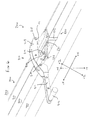
- FIG. 1 is a diagram that illustrates an exemplary awning vent 100 with an exemplary locking mechanism as is known in the art.
- the exemplary locking mechanism of the exemplary awning vent 100 may comprise, as an example, a handle 101 , handle connectors 102 , main transmission bars 103 , transmission device connectors 104 , 105 , 110 , corner transmission device housings 106 , keepers 107 , locking points 108 , side transmission bars 109 , and friction hinges 111 .
- the handle 101 can attach to an inner portion of the sash. Certain components on an underside of the handle 101 may extend through the sash to an outer portion of the sash.
- the handle connectors 102 may couple to the underside of the handle 101 at the outer portion of the sash and slidably fit in a euro-grove (not shown) that extends around an outer perimeter of the sash.
- Transmission bars 103 can attach to the handle connectors 102 at one end and corner transmission device connectors 104 at the other end, and may slidably fit in the euro-grove.
- the corner transmission device connectors 104 may slidably fit into corner transmission device housings 106 . An outward, horizontal force on corner transmission device connectors 104 may cause the corner transmission device connectors 104 to extend into the corner transmission device housings 106 , which in turn may cause the corner transmission device connectors 105 to extend vertically in the exemplary awning vent illustrated in FIG. 1 .
- side transmission bars 109 may attach to the corner transmission device connectors 105 at one end and transmission device connectors 110 at the other end, and may slidably fit in the euro-grove.
- Friction hinges 111 can attach to the sash and vent frame on both sides of the exemplary awning vent 100 and may be operable to guide and support the sash when venting as well as limit the opening range of the sash.
- Locking points 108 may be attached to, or integrated with, one or more transmission bars 103 , 109 , or other components of the vent locking mechanism such as the transmission device connectors 104 , 105 , and 110 , and may engage (or mate) with keepers 107 , positioned at corresponding points on the vent frame, when moved by the handle 101 to the locking position.
- the engaging of the locking points 108 with the keepers 107 results in compression of the sash to the vent frame to make a tight seal.
- the larger the vent 100 the more locking points 108 and keepers 107 are needed to achieve an adequate seal. Further, the more locking points 108 and keepers 107 , the more force is needed to lock and unlock the vent.
- FIG. 1 is a diagram that illustrates an exemplary awning vent with an exemplary locking mechanism as is known in the art.
- FIG. 2 is a diagram that illustrates a perspective view of an exemplary double-acting lever mechanism in a locked/closed position and comprising an exemplary lever and an exemplary swing arm base in accordance with an embodiment of the present invention.
- FIG. 3 is a diagram that illustrates a perspective view of an exemplary double-acting lever mechanism in an unlocked/closed position and comprising an exemplary lever and an exemplary swing arm base in accordance with an embodiment of the present invention.
- FIG. 4 is a diagram that illustrates a perspective view of an exemplary double-acting lever mechanism in an unlocked/open position and comprising an exemplary lever and an exemplary swing arm base in accordance with an embodiment of the present invention.
- FIG. 5 is a diagram that illustrates a perspective view of an exemplary double-acting lever mechanism in a locked/closed position and comprising an exemplary lever and an exemplary stationary base in accordance with an embodiment of the present invention.
- FIG. 6 is a diagram that illustrates a perspective view of an exemplary double-acting lever mechanism in an unlocked/closed position and comprising an exemplary lever and an exemplary stationary base in accordance with an embodiment of the present invention.
- FIG. 7 is a diagram that illustrates a perspective view of an exemplary double-acting lever mechanism in an unlocked/open position and comprising an exemplary lever and an exemplary stationary base in accordance with an embodiment of the present invention.
- FIG. 8 is a flow diagram that illustrates exemplary steps for unlocking, opening, closing and locking a vent sash in accordance with an embodiment of the present invention.
- Certain embodiments of the invention may be found in systems and methods for unlocking/locking and opening/closing windows without excessive force and twisting. More specifically, certain embodiments provide a double-acting lever mechanism 200 configured to unlock/lock an operable vent sash by pivoting substantially ninety degrees about a locking mechanism interface 101 and configured to open/close the operable vent sash by pivoting an additional substantially ninety degrees about the locking mechanism interface 101 .
- the force required to pivot the lever mechanism 200 for any operation does not exceed five (5) pounds (lbs.).
- the lever mechanism system 200 may comprise a base 220 , 230 configured to fixably attach to at least one of a vent stop 330 and a window frame 400 .
- the lever mechanism system 200 may comprise a lever 210 rotatably or slidably attached to the base 220 , 230 .
- the lever 210 may be configured to pivotably attach to a locking mechanism interface 101 of the vent sash 310 .
- the lever 210 may be configured to pivot substantially ninety degrees in a first direction to an unlocked position.
- the lever 210 may be configured to pivot substantially ninety degrees in a second direction to an open position.
- the lever 210 may be configured to pivot substantially ninety degrees in a third direction to a closed position.
- the lever 210 may be configured to pivot substantially ninety degrees in a fourth direction to a locked position.
- Certain embodiments provide a method 800 for unlocking, opening, closing and locking a vent sash 310 .
- the method may comprise pivoting 810 a lever 210 substantially ninety degrees in a first direction to an unlocked position.
- the method 800 may comprise pivoting 820 the lever 210 substantially ninety degrees in a second direction to an open position.
- the method 800 may comprise pivoting 830 the lever 210 substantially ninety degrees in a third direction to a closed position.
- the method 800 may comprise pivoting 840 the lever 210 substantially ninety degrees in a fourth direction to a locked position.
- FIG. 2 is a diagram that illustrates a perspective view of an exemplary double-acting lever mechanism 200 in a locked/closed position, and comprising an exemplary lever 210 and an exemplary swing arm base 220 in accordance with an embodiment of the present invention.
- FIG. 3 is a diagram that illustrates a perspective view of an exemplary double-acting lever mechanism 200 in an unlocked/closed position, and comprising an exemplary lever 210 and an exemplary swing arm base 220 .
- FIG. 4 is a diagram that illustrates a perspective view of an exemplary double-acting lever mechanism 200 in an unlocked/open position, and comprising an exemplary lever 210 and an exemplary swing arm base 220 .
- an exemplary double-acting lever mechanism 200 comprising an exemplary lever 210 and an exemplary swing arm base 220 . Also illustrated in FIGS. 2-4 are a window frame 400 and a vent 300 .
- the vent can comprise a sash 310 , glass 320 and vent stop 330 , for example.
- the exemplary double-acting lever mechanism 200 is illustrated in three-dimensions comprising an X axis, a Y axis and a Z axis.
- the ⁇ X direction refers to the left direction, for example.
- the +X direction refers to the right direction, for example.
- the ⁇ Y direction refers to the down direction, for example.
- the +Y direction refers to the up direction, for example.
- the ⁇ Z direction refers to the direction away from the glass 320 , for example.
- the +Z direction refers to the direction toward the glass 320 , for example.
- the swing arm base 220 may comprise a main swing arm pivot 221 , a swing arm housing 222 , a detent pin 223 , a secondary swing arm pivot 224 and a secondary swing arm pivot support 225 .
- the main swing arm pivot 221 may be a pin, screw or any suitable pivotable attachment mechanism.
- the main swing arm pivot 221 attaches and extends through the swing arm housing 222 and attaches to one or more of the vent stop 330 of the vent 300 , and the window frame 400 .
- the main swing arm pivot 221 supports the swing arm housing 222 when pivoting substantially ninety (90) degrees (i.e., 85-95 degrees) in the +X/ ⁇ Z and ⁇ X/+Z directions, for example, between locked (as illustrated in FIG.
- the main swing arm pivot 211 supports a fulcrum 216 when the lever 210 pivots substantially ninety (90) degrees (i.e., 85-95 degrees) in the +Y/+Z and ⁇ Y/ ⁇ Z directions, for example, between unlocked/closed (as illustrated in FIG. 3 ) and open (as illustrated in FIG. 4 ) positions as discussed in more detail below.
- the swing arm housing 222 couples to the main swing arm pivot 221 and the secondary swing arm pivot 224 .
- the secondary swing arm pivot 224 may be a pin, screw or any suitable pivotable attachment mechanism.
- the swing arm housing 222 may fit partially and rotatably within the secondary swing arm pivot support 225 , which also attaches to the secondary swing arm pivot 224 , at a secondary swing arm pivot 224 end of the swing arm housing 222 .
- the swing arm housing 222 comprises grooves 226 on top and bottom portions of the swing arm housing 222 such that a detent pin 223 can extend through the swing arm housing 222 and be movable within grooves 226 .
- material such as rubber or plastic may wrap around a bottom end of the detent pin 223 that extends through the bottom groove of the swing arm housing 222 , such that a support leg 228 is formed to contact the window frame 400 when in the unlocked positions (as illustrated in FIGS. 3-4 ) such that the swing arm base 220 is stabilized on the window frame 400 by the support leg 228 .
- a support stop (not shown) may be fixably attached to the window frame 400 for engaging or wedging under the swing arm base 220 when the swing arm base is in the unlocked positions (as illustrated in FIGS. 3-4 ).
- the swing arm housing 222 houses a spring 227 and the portions of the detent pin 223 , main swing arm pivot 221 and secondary swing arm pivot 224 that extend through swing arm housing 222 .
- the spring 227 attaches to the secondary swing arm pivot 224 and the detent pin 223 within the housing, biasing the detent pin 223 towards a secondary swing arm pivot end of grooves 226 .
- the spring arm base 220 attaches to lever 210 at a fulcrum connection 217 as discussed in more detail below.
- the swing arm base 220 pivots about the main swing arm pivot 221 .
- the secondary swing arm pivot support 225 pivots about the secondary swing arm pivot 224 .
- the swing arm pivot support 225 contacts and biases the detent pin 223 towards a main swing arm pivot end of grooves 226 , which locks and stabilizes the lever mechanism 200 in the unlocked position (as illustrated in FIGS. 3-4 ).
- the biasing of the detent pin 223 towards the main swing arm pivot end of grooves 226 by the secondary swing arm pivot support 225 causes the support leg 228 portion of the detent pin 223 to contact the window frame 400 , which provides further locking and stabilization of the lever mechanism 200 in the unlocked position (as illustrated in FIGS. 3-4 ).
- the swing arm base 220 pivots about the main swing arm pivot 221 .
- the secondary swing arm pivot support 225 pivots about the secondary swing arm pivot 224 .
- the swing arm pivot support 225 pivots away from the detent pin 223 , allowing the detent pin 223 to bias towards the secondary swing arm pivot end of grooves 226 , which releases the locking and stabilization of the lever mechanism 200 such that it may pivot to the locked position (as illustrated in FIG. 2 ).
- FIG. 5 is a diagram that illustrates a perspective view of an exemplary double-acting lever mechanism 200 in a locked/closed position and comprising an exemplary lever 210 and an exemplary stationary base 230 in accordance with an embodiment of the present invention.
- FIG. 6 is a diagram that illustrates a perspective view of an exemplary double-acting lever mechanism 200 in an unlocked/closed position and comprising an exemplary lever 210 and an exemplary stationary base 230 .
- FIG. 7 is a diagram that illustrates a perspective view of an exemplary double-acting lever mechanism 200 in an unlocked/open position and comprising an exemplary lever 210 and an exemplary stationary base 230 .
- an exemplary double-acting lever mechanism 200 comprising an exemplary lever 210 and an exemplary stationary base 230 . Also illustrated in FIGS. 5-7 are a window frame 400 and a vent 300 .
- the vent can comprise a sash 310 , glass 320 and vent stop 330 , for example.
- the exemplary double-acting lever mechanism 200 is illustrated in three-dimensions comprising an X axis, a Y axis and a Z axis.
- the ⁇ X direction refers to the left direction, for example.
- the +X direction refers to the right direction, for example.
- the ⁇ Y direction refers to the down direction, for example.
- the +Y direction refers to the up direction, for example.
- the ⁇ Z direction refers to the direction away from the glass 320 , for example.
- the +Z direction refers to the direction toward the glass 320 , for example.
- the stationary base 230 comprises a stationary track 231 and one or more stationary supports 232 .
- the stationary track 231 may be substantially a semi-circle (e.g., approximately 180 degrees) or between approximately 90-200 degrees (e.g., a half of a semi-circle) and can at least partially wrap around a vent handle 101 or any suitable interface to a vent locking mechanism.
- the stationary track 231 may extend over, but not fixably attach to, sash 310 , at least on one side of vent handle 101 , such that lever 210 may be substantially parallel to glass 320 and substantially above sash 310 when in a locked position (as illustrated in FIG. 5 ).
- the stationary support(s) 232 attach to the stationary track 231 and one or more of the vent stop 330 and window frame 400 .
- the stationary support(s) 232 supports the stationary track 231 in a fixed position about the vent handle 101 .
- the stationary base 230 slidably attaches to lever 210 at a fulcrum connection 217 , which allows the lever 210 to slide substantially ninety (90) degrees in the +X/ ⁇ Z and ⁇ X/+Z directions, for example, between locked (as illustrated in FIG. 5 ) and unlocked (as illustrated in FIG. 6 ) positions, as discussed in more detail below.
- Double-acting refers to the two separate and distinct actions (e.g., locking/unlocking and opening/closing) provided by the lever mechanism 200 by pivoting in two separate and distinct ninety (90) degree (i.e., 85-95 degrees) directions (e.g., +X/ ⁇ Z to unlock and +Y/+Z to open or ⁇ Y/ ⁇ Z to close and ⁇ X/+Z to lock).
- 90 degree i.e. 85-95 degrees
- FIGS. 2 and 5 illustrate a lever arm 211 of the lever mechanism 200 extending in the ⁇ X direction
- the lever mechanism 200 could similarly be configured to extend in the +X direction.
- FIGS. 2-3 and 5-6 illustrate unlocking as pivoting in the +X/ ⁇ Z direction and locking as pivoting in the ⁇ X/+Z direction
- unlocking may be provided by pivoting in the ⁇ X/ ⁇ Z direction and locking can be provided by pivoting in the +X/+Z, for example.
- FIGS. 3-4 and 6-7 illustrate the lever mechanism 200 pivoting in the +Y/+Z direction to open the sash 310 and pivoting in the ⁇ Y/ ⁇ Z direction to close the sash 310
- the lever mechanism may be configured to pivot in the +X/+Z direction to open the sash 310 and pivot in the ⁇ X/ ⁇ Z direction to close the sash 310 , or vice versa, among other things, by reconfiguring/rotating components of the lever 210 by approximately ninety (90) degrees, for example.
- the lever 210 may comprise a lever arm 211 , a lever handle 212 , a push arm 213 , a lever arm pivot 214 , a pivotable sash attachment 215 , a fulcrum 216 and a fulcrum connection 217 .
- the fulcrum connection 217 rotatably couples the lever 210 to the swing arm base 220 at swing arm housing 222 using a pin, screw or any suitable rotatable attachment mechanism.
- the fulcrum connection 217 slidably attaches the lever 210 to the stationary base 230 at stationary track 231 using any suitable slidable attachment mechanism.
- the fulcrum connection 217 pivots with swing arm base 220 or slides with stationary base 230 between unlocked and locked positions (as illustrated in FIGS. 2-3 and 5-6 ).
- a first end of a push arm 213 of the lever 210 attaches to a vent handle 101 , or any suitable interface to a vent locking mechanism, at pivotable sash attachment 215 , which may be a pin, screw or any suitable pivotable attachment mechanism.
- the pivotable sash attachment 215 may be detachably coupled to the vent locking mechanism interface 101 using a quick release pin or any suitable releasable, pivotable attachment mechanism.
- a second end of the push arm 213 couples to a lever arm 211 at lever arm pivot 214 , which may be a pin, screw or any suitable pivotable attachment mechanism.
- the lever arm 211 attaches at one end to the fulcrum 216 , which may be a pin, screw, or any suitable rotatable connection, at fulcrum connection 217 .
- a lever handle 212 which may be any suitable mechanism to grasp and pivot the lever 210 , may be attached to or integrated with lever arm 211 .
- the lever arm 211 may be telescopic and/or otherwise collapsible, foldable, or the like.
- the lever handle 212 may be collapsible, foldable or the like.
- the lever 210 pivots at the pivotable sash attachment 215 , and pivots with swing arm base 220 or slides with stationary base 230 at fulcrum connection 217 .
- FIG. 8 is a flow diagram that illustrates exemplary steps for unlocking, opening, closing and locking a vent sash 310 in accordance with an embodiment of the present invention.
- a flow diagram 800 which illustrates exemplary steps for unlocking, opening, closing and locking a vent sash 310 .
- a lever 210 is pivoted substantially ninety (90) degrees in a first direction to an unlocked position.
- the lever 210 is pivoted substantially ninety (90) degrees in a second direction to an open position.
- the lever 210 is pivoted substantially ninety (90) degrees in a third direction to a closed position.
- the lever 210 is pivoted substantially ninety (90) degrees in a fourth direction to a locked position.
- a lever 210 is pivoted substantially ninety (90) degrees in a first direction to an unlocked position.
- the first direction may be the +X/ ⁇ Z direction, although other directions are contemplated as discussed above.
- the lever 210 may be pivoted using the lever handle 213 .
- Certain embodiments provide that the lever 210 pivots at the pivotable sash attachment 215 , and pivots with swing arm base 220 or slides with stationary base 230 at fulcrum connection 217 .
- the lever 210 may initially be positioned substantially parallel to glass 320 and over sash 310 , and may pivot to a position substantially perpendicular to glass 320 .
- the swing arm base 220 pivots about the main swing arm pivot 221 .
- the secondary swing arm pivot support 225 pivots about the secondary swing arm pivot 224 .
- the swing arm pivot support 225 contacts and biases the detent pin 223 towards a main swing arm pivot end of grooves 226 , which locks and stabilizes the lever mechanism 200 in the unlocked position (as illustrated in FIGS. 3-4 ).
- the biasing of the detent pin 223 towards the main swing arm pivot end of grooves 226 by the secondary swing arm pivot support 225 causes the support leg 228 portion of the detent pin 223 to contact the window frame 400 , which provides further locking and stabilization of the lever mechanism 200 in the unlocked position (as illustrated in FIGS. 3-4 ).
- the lever 210 is pivoted substantially ninety (90) degrees in a second direction to an open position.
- the second direction may be the +Y/+Z direction, although other directions are contemplated as discussed above.
- the second direction is different than the first direction.
- the lever 210 may be pivoted using the lever handle 213 . Certain embodiments provide that the lever arm 211 pivots at the lever arm pivot 214 and the fulcrum 216 , while the push arm 213 pivots at the lever arm pivot 214 and the pivotable sash attachment 215 to open the sash 310 .
- the lever 210 is pivoted substantially ninety (90) degrees in a third direction to a closed position.
- the third direction may be the ⁇ Y/ ⁇ Z direction, although other directions are contemplated as discussed above.
- the third direction is different than the first and second directions.
- the third direction is opposite the second direction.
- the lever 210 may be pivoted using the lever handle 213 . Certain embodiments provide that the lever arm 211 pivots at the lever arm pivot 214 and the fulcrum 216 , while the push arm 213 pivots at the lever arm pivot 214 and the pivotable sash attachment 215 to close the sash 310 .
- the lever 210 is pivoted substantially ninety (90) degrees in a fourth direction to a locked position.
- the fourth direction may be the ⁇ X/+Z direction, although other directions are contemplated as discussed above.
- the fourth direction is different than the first, second and third directions.
- the fourth direction is opposite the first direction.
- the lever 210 may be pivoted using the lever handle 213 . Certain embodiments provide that the lever 210 pivots at the pivotable sash attachment 215 , and pivots with swing arm base 220 or slides with stationary base 230 at fulcrum connection 217 .
- the lever 210 may initially be positioned substantially perpendicular to glass 320 , and may pivot to a position substantially parallel to glass 320 and over sash 310 .
- the swing arm base 220 pivots about the main swing arm pivot 221 .
- the secondary swing arm pivot support 225 pivots about the secondary swing arm pivot 224 .
- the swing arm pivot support 225 pivots away from the detent pin 223 , allowing the detent pin 223 to bias towards the secondary swing arm pivot end of grooves 226 , which releases the locking and stabilization of the lever mechanism 200 such that it may pivot to the locked position (as illustrated in FIG. 2 ).
- the force required to pivot the lever mechanism 200 , to both lock/unlock and open/close the vent sash 310 does not exceed five (5) pounds (lbs.), irrespective of the size and weight of the vent sash 310 .
- pivoting the lever mechanism 200 substantially ninety (90) degrees in a second direction to open/close the vent sash does not involve excessive twisting or turning of an operator's wrist.
- the lever mechanism 200 may be retrofitted to fit an existing vent handle 101 or replace an existing vent handle 101 such that the lever mechanism 200 operates with an existing locking mechanism of a vent 300 . Additionally and/or alternatively, the lever mechanism 200 may be manufactured as a part of a locking mechanism of a vent 300 .
- the lever 210 may restrict or limit the distance the vent sash 310 may open. Further, the lever 210 can help secure and support the vent sash 310 such that it does not blow out from negative pressure when in an open position.
- the lever 210 and/or base 220 , 230 may comprise a catch, lock, snap, or any suitable locking mechanism (not shown) configured to secure the lever 210 in the locked position and to provide additional compression and sealing of the vent sash 310 .
- the lever mechanism system 200 may comprise a base 220 , 230 configured to fixably attach to one or more of a vent stop 330 and a window frame 400 .
- the lever mechanism system 200 may comprise a lever 210 rotatably or slidably attached to the base 220 , 230 .
- the lever 210 may be configured to pivotably attach to a locking mechanism interface 101 of the vent sash 310 .
- the lever 210 may be configured to pivot substantially ninety degrees in a first direction to an unlocked position.
- the lever 210 may be configured to pivot substantially ninety degrees in a second direction to an open position.
- the lever 210 may be configured to pivot substantially ninety degrees in a third direction to a closed position.
- the lever 210 may be configured to pivot substantially ninety degrees in a fourth direction to a locked position.
- the first, second, third and fourth directions are different directions.
- the first direction is opposite the fourth direction.
- the second direction is opposite the third direction.
- the locking mechanism interface may be a vent handle 101 of a locking mechanism.
- the locking mechanism comprises a plurality of locking points 108 for disengageably coupling to a corresponding plurality of keepers 107 .
- the lever 210 may comprise a push arm 213 including a first push arm end and a second push arm end.
- the first push arm end may be configured to pivotably attach to the locking mechanism interface 101 at a pivotable sash attachment 215 .
- the second push arm end may be configured to pivotably attach to a lever arm 211 at a lever arm pivot 214 .
- the lever 210 may comprise the lever arm including a first lever arm end and a second lever arm end.
- the first lever arm end may be configured to pivotably attach to a fulcrum 216 at a fulcrum connection 217 .
- the second lever arm end at least one of attaches to a lever handle 212 , and integrates with the lever handle 212 .
- the lever 210 may comprise the fulcrum connection 217 configured to rotatably or slidably attach the lever 210 to the base 220 , 230 .
- the fulcrum connection 217 may rotate or slide with the base 220 , 230 between the unlocked and the locked positions.
- the pivotable sash attachment 215 is a quick release pin detachably coupled to the locking mechanism interface 101 .
- the lever arm 211 is one or more of telescopic, collapsible, and foldable.
- the lever handle 212 is at least one of collapsible and foldable.
- the lever 210 pivots at the pivotable sash attachment 215 , and pivots or slides with the base 220 , 230 at the fulcrum connection 217 , when pivoting substantially ninety degrees in the first direction and the fourth direction between the locked position and the unlocked position using the lever handle 212 .
- the lever arm 211 pivots at the lever arm pivot 214 and the fulcrum 216
- the push arm 213 pivots at the lever arm pivot 214 and the pivotable sash attachment 215 , when pivoting the lever 210 substantially ninety degrees in the second direction and the third direction between the open position and the closed position using the lever handle 212 .
- the base 220 comprises a main swing arm pivot 221 configured to pivotably attach and extend through a swing arm housing 222 .
- the main swing arm pivot 221 may fixably attach to one or more of the vent stop 330 and the window frame 400 .
- the main swing arm pivot 221 supports the swing arm housing 222 when pivoting substantially ninety degrees in the first direction and the fourth direction between the locked position and the unlocked position.
- the main swing arm pivot 221 supports the lever 210 when pivoting substantially ninety degrees in the second direction and the third direction between the closed position and the open position.
- the base 220 comprises the swing arm housing 222 configured to pivotably attach to the main swing arm pivot 221 , a secondary swing arm pivot 224 , and the lever 210 .
- the swing arm housing 222 fits partially and rotatably within a secondary swing arm pivot support 225 attached to the secondary swing arm pivot 224 .
- the swing arm housing 222 comprises a top portion groove 226 and a bottom portion groove 226 .
- the top portion groove 226 and bottom portion groove 226 comprises a main swing arm pivot end and a secondary swing arm pivot end.
- the base 220 comprises a detent pin 223 configured to extend through the top portion groove 226 and the bottom portion groove 226 of the swing arm housing 222 .
- the detent pin 223 may be configured to attach to the secondary swing arm pivot 224 via a spring 227 .
- a portion of the detent pin 228 extending through the bottom portion groove 226 is configured to engage the window frame 400 when the detent pin 223 is biased by the secondary swing arm pivot support 225 towards the main swing arm pivot end of the bottom portion groove 226 .
- the portion of the detent pin 228 extending through the bottom portion groove 226 is configured to disengage the window frame 400 when the detent pin 223 is biased by the spring 227 to the secondary swing arm pivot end of the bottom portion groove 226 .
- the base 230 comprises a stationary track 231 configured to at least partially wrap around the locking mechanism interface 101 and slidably attach to the lever 210 .
- the stationary track 231 may be between ninety (90) and two hundred (200) degrees of a substantially semicircular shape.
- the base 230 may comprise one or more stationary supports 232 configured to attach to the stationary track 231 and one or more of the vent stop 330 and the window frame 400 to support the stationary track 231 in a fixed position.
- a force applied to pivot the lever 210 substantially ninety degrees in each of the first direction, the second direction, the third direction and the fourth direction does not exceed five pounds.
- the lever 210 restricts an amount the vent sash is opened.
- Various embodiments provide a method 800 for unlocking, opening, closing and locking a vent sash 310 .
- the method may comprise pivoting 810 a lever 210 substantially ninety degrees in a first direction to an unlocked position.
- the method 800 may comprise pivoting 820 the lever 210 substantially ninety degrees in a second direction to an open position.
- the method 800 may comprise pivoting 830 the lever 210 substantially ninety degrees in a third direction to a closed position.
- the method 800 may comprise pivoting 840 the lever 210 substantially ninety degrees in a fourth direction to a locked position.
- the first, second, third and fourth directions are different directions.
- the first direction is opposite the fourth direction.
- the second direction is opposite the third direction.
- the lever 210 interfaces with a locking mechanism of the vent sash 310 , the locking mechanism comprising a plurality of locking points 108 for disengageably coupling to a corresponding plurality of keepers 107 .
- the lever 210 attaches to a base 220 , 230 .
- the base 220 , 230 may attach to one or more of a window frame 400 and a vent stop 330 .
- the base 220 , 230 may be one or more of a stationary base 230 and a pivotable swing arm base 220 .
- a force applied to pivot the lever 210 substantially ninety degrees in each of the first direction, the second direction, the third direction and the fourth direction does not exceed five pounds.
Abstract
Description
Claims (23)
Priority Applications (2)
| Application Number | Priority Date | Filing Date | Title |
|---|---|---|---|
| US13/540,878 US9404302B2 (en) | 2012-07-03 | 2012-07-03 | Systems and methods for unlocking/locking and opening/closing windows |
| US13/663,798 US9273763B2 (en) | 2012-07-03 | 2012-10-30 | Systems and methods for unlocking/locking and opening/closing windows |
Applications Claiming Priority (1)
| Application Number | Priority Date | Filing Date | Title |
|---|---|---|---|
| US13/540,878 US9404302B2 (en) | 2012-07-03 | 2012-07-03 | Systems and methods for unlocking/locking and opening/closing windows |
Related Child Applications (1)
| Application Number | Title | Priority Date | Filing Date |
|---|---|---|---|
| US13/663,798 Continuation-In-Part US9273763B2 (en) | 2012-07-03 | 2012-10-30 | Systems and methods for unlocking/locking and opening/closing windows |
Publications (2)
| Publication Number | Publication Date |
|---|---|
| US20140007734A1 US20140007734A1 (en) | 2014-01-09 |
| US9404302B2 true US9404302B2 (en) | 2016-08-02 |
Family
ID=49877522
Family Applications (1)
| Application Number | Title | Priority Date | Filing Date |
|---|---|---|---|
| US13/540,878 Expired - Fee Related US9404302B2 (en) | 2012-07-03 | 2012-07-03 | Systems and methods for unlocking/locking and opening/closing windows |
Country Status (1)
| Country | Link |
|---|---|
| US (1) | US9404302B2 (en) |
Cited By (1)
| Publication number | Priority date | Publication date | Assignee | Title |
|---|---|---|---|---|
| US11448007B2 (en) * | 2019-02-19 | 2022-09-20 | Marvin Lumber And Cedar Company, Llc | Low profile panel handle assembly and methods for same |
Families Citing this family (1)
| Publication number | Priority date | Publication date | Assignee | Title |
|---|---|---|---|---|
| US10125529B2 (en) * | 2015-05-13 | 2018-11-13 | Reflection Window Company, Llc | System for unlocking/locking and opening/closing windows |
Citations (52)
| Publication number | Priority date | Publication date | Assignee | Title |
|---|---|---|---|---|
| US949359A (en) * | 1908-07-13 | 1910-02-15 | John A Johnson | Sash-fastener. |
| US2295778A (en) * | 1938-09-02 | 1942-09-15 | Miner Inc W H | Hatch cover fastener |
| US2791456A (en) | 1954-06-14 | 1957-05-07 | Treco Products Co Inc | Sill window adjusting device |
| US3091978A (en) | 1961-02-09 | 1963-06-04 | Gen Slicing Machine Co Inc | Swivelled cranks |
| US3633315A (en) | 1970-11-02 | 1972-01-11 | Massey Ferguson Inc | Closure controller |
| US3927492A (en) | 1974-09-16 | 1975-12-23 | Le Van Specialty Company Inc | Quick release hinged vehicle window |
| US3974753A (en) | 1975-03-10 | 1976-08-17 | Lois Loreen Sanchez | Automobile roof vent |
| US4086727A (en) * | 1976-01-29 | 1978-05-02 | Rolscreen Company | Pivot window construction |
| US4136578A (en) | 1977-02-17 | 1979-01-30 | Truth Incorporated | Closure operator |
| US4195866A (en) | 1978-11-16 | 1980-04-01 | General Motors Corporation | Lock for removable roof closure latch mechanism |
| US4206939A (en) | 1978-11-13 | 1980-06-10 | Ford Motor Company | Latch assembly for vent windows and the like |
| US4257632A (en) | 1979-01-22 | 1981-03-24 | Le Van Specialty Co., Inc. | Detachable latching device for closure panels |
| US4300794A (en) | 1979-12-11 | 1981-11-17 | Peachtree Doors, Inc. | Closure fastener |
| US4350376A (en) | 1978-11-03 | 1982-09-21 | Regie Nationale Des Usines Renault | Locking device for swiveling window |
| US4392329A (en) * | 1980-12-11 | 1983-07-12 | Nippon Elumin Sash Co., Ltd. | Pivotable window moved between locked and opened positions by means of a single operating handle |
| US4435007A (en) | 1980-05-08 | 1984-03-06 | Regie Nationale Des Usines Renault | Locking device for pivoting window |
| US4466644A (en) | 1982-01-18 | 1984-08-21 | Levan Specialty Co., Inc. | Multi-positioning latch assembly |
| US4469370A (en) | 1981-12-21 | 1984-09-04 | Petersen Robert J | Sunroof with detachable connector |
| US4484773A (en) | 1982-09-13 | 1984-11-27 | Levan Specialty Co., Inc. | Detachable low-profile latch assembly for releasably hinged closure panels |
| US4534587A (en) | 1983-01-28 | 1985-08-13 | W & F Manufacturing, Inc. | Latch assembly |
| US4615236A (en) | 1984-01-11 | 1986-10-07 | Vermeulen-Hollandia Octrooien Ii B.V. | Crank device for an open roof construction for a vehicle |
| US4618176A (en) | 1982-12-15 | 1986-10-21 | ASC Auto Spezial Carosserie Vertrieb GmbH | Window opener |
| US4923232A (en) | 1986-10-30 | 1990-05-08 | Aisin Seiki Kabushiki Kaisha | Window apparatus for vehicle |
| US4928547A (en) | 1987-10-19 | 1990-05-29 | Vermeulen-Hollandia Octrooien Ii B.V. | Crank device |
| US4937976A (en) | 1989-09-22 | 1990-07-03 | Truth Incorporated | Window operator and hinge structure |
| US5168770A (en) | 1991-08-15 | 1992-12-08 | Ellis Frederick G | Pivotal handle for a window actuator |
| US5201241A (en) | 1992-02-24 | 1993-04-13 | Pollack Jr Edward | Window crank handle apparatus |
| US5346267A (en) | 1992-01-14 | 1994-09-13 | Britax Weathershields Limited | Latch for hinged panel |
| US5400473A (en) | 1993-08-27 | 1995-03-28 | Great Lakes Window Inc. | Foldaway window crank handle with a handle retention spring |
| US5410778A (en) | 1993-08-30 | 1995-05-02 | Langevin; Yves | Crank handle for window pane or the like |
| US5438801A (en) | 1993-07-01 | 1995-08-08 | Asmo Co., Ltd. | Quarter window opening/closing apparatus |
| US5467503A (en) | 1992-05-13 | 1995-11-21 | Truth Hardware Corporation | Handle and cover assembly for a window operator |
| US5560082A (en) | 1994-09-15 | 1996-10-01 | Truth Hardware Corporation | Folding window operator handle |
| US5740632A (en) | 1995-05-18 | 1998-04-21 | Andersen Corporation | Multi-position window operator handle |
| US5802673A (en) | 1997-05-19 | 1998-09-08 | Dero Enterprises, Inc. | Crank handle for actuating a window pane |
| US5901501A (en) | 1996-08-29 | 1999-05-11 | Interlock Group Limited | Window fastener |
| US5937582A (en) | 1993-12-22 | 1999-08-17 | Interlock Industries Limited | Rotary window operator |
| US6032990A (en) | 1998-08-12 | 2000-03-07 | Dura Automotive Systems, Inc. | Adjustable latch for window assembly |
| US6035492A (en) | 1997-07-11 | 2000-03-14 | Warshaviak; Jehuda T. | Handle |
| US6102456A (en) | 1996-11-20 | 2000-08-15 | Inalfa Industries B.V. | Operating means for an open roof construction, as well as an open construction |
| US6164156A (en) | 1999-06-03 | 2000-12-26 | Newell Operating Company | Window operator |
| US6450063B1 (en) | 1999-04-29 | 2002-09-17 | Interlock Group Limited | Folding handle |
| US6598265B2 (en) * | 2000-09-09 | 2003-07-29 | 3 G Technology | Handle structure of an apparatus for opening and closing a window |
| US6612628B1 (en) | 1999-03-30 | 2003-09-02 | Richard Fritz Gmbh & Co. Kg | Adjusting device for hinged windows |
| US6640389B2 (en) | 2000-12-06 | 2003-11-04 | Pella Corporation | Casement window operating assembly |
| US20040183314A1 (en) * | 2003-03-20 | 2004-09-23 | Klompenburg Marlo Van | Combination folding crank handle and lock |
| US6908124B2 (en) | 2001-07-19 | 2005-06-21 | Societa Italiana Vetra - Siv S.P.A. | Catch device for a pivoting window |
| US7147256B2 (en) | 2004-03-26 | 2006-12-12 | Newell Operating Company | Fold down window operator |
| US7194930B2 (en) | 2002-08-23 | 2007-03-27 | Assa Abloy Financial Services Ab | Handle |
| US7251860B2 (en) | 2005-05-19 | 2007-08-07 | Luke Liang | Window rotating handle |
| US20100038926A1 (en) * | 2008-08-14 | 2010-02-18 | Williamson Scott A | Clamp mechanism for a cover assembly |
| US7905536B2 (en) * | 2009-04-24 | 2011-03-15 | Cyc Engineering, Inc. | Clamp structure for tonneau cover |
-
2012
- 2012-07-03 US US13/540,878 patent/US9404302B2/en not_active Expired - Fee Related
Patent Citations (54)
| Publication number | Priority date | Publication date | Assignee | Title |
|---|---|---|---|---|
| US949359A (en) * | 1908-07-13 | 1910-02-15 | John A Johnson | Sash-fastener. |
| US2295778A (en) * | 1938-09-02 | 1942-09-15 | Miner Inc W H | Hatch cover fastener |
| US2791456A (en) | 1954-06-14 | 1957-05-07 | Treco Products Co Inc | Sill window adjusting device |
| US3091978A (en) | 1961-02-09 | 1963-06-04 | Gen Slicing Machine Co Inc | Swivelled cranks |
| US3633315A (en) | 1970-11-02 | 1972-01-11 | Massey Ferguson Inc | Closure controller |
| US3927492A (en) | 1974-09-16 | 1975-12-23 | Le Van Specialty Company Inc | Quick release hinged vehicle window |
| US3974753A (en) | 1975-03-10 | 1976-08-17 | Lois Loreen Sanchez | Automobile roof vent |
| US4086727A (en) * | 1976-01-29 | 1978-05-02 | Rolscreen Company | Pivot window construction |
| US4136578A (en) | 1977-02-17 | 1979-01-30 | Truth Incorporated | Closure operator |
| US4350376A (en) | 1978-11-03 | 1982-09-21 | Regie Nationale Des Usines Renault | Locking device for swiveling window |
| US4206939A (en) | 1978-11-13 | 1980-06-10 | Ford Motor Company | Latch assembly for vent windows and the like |
| US4195866A (en) | 1978-11-16 | 1980-04-01 | General Motors Corporation | Lock for removable roof closure latch mechanism |
| US4257632A (en) | 1979-01-22 | 1981-03-24 | Le Van Specialty Co., Inc. | Detachable latching device for closure panels |
| US4300794A (en) | 1979-12-11 | 1981-11-17 | Peachtree Doors, Inc. | Closure fastener |
| US4435007A (en) | 1980-05-08 | 1984-03-06 | Regie Nationale Des Usines Renault | Locking device for pivoting window |
| US4392329A (en) * | 1980-12-11 | 1983-07-12 | Nippon Elumin Sash Co., Ltd. | Pivotable window moved between locked and opened positions by means of a single operating handle |
| US4469370A (en) | 1981-12-21 | 1984-09-04 | Petersen Robert J | Sunroof with detachable connector |
| US4466644A (en) | 1982-01-18 | 1984-08-21 | Levan Specialty Co., Inc. | Multi-positioning latch assembly |
| US4484773A (en) | 1982-09-13 | 1984-11-27 | Levan Specialty Co., Inc. | Detachable low-profile latch assembly for releasably hinged closure panels |
| US4618176A (en) | 1982-12-15 | 1986-10-21 | ASC Auto Spezial Carosserie Vertrieb GmbH | Window opener |
| US4534587A (en) | 1983-01-28 | 1985-08-13 | W & F Manufacturing, Inc. | Latch assembly |
| US4615236A (en) | 1984-01-11 | 1986-10-07 | Vermeulen-Hollandia Octrooien Ii B.V. | Crank device for an open roof construction for a vehicle |
| US4923232A (en) | 1986-10-30 | 1990-05-08 | Aisin Seiki Kabushiki Kaisha | Window apparatus for vehicle |
| US4928547A (en) | 1987-10-19 | 1990-05-29 | Vermeulen-Hollandia Octrooien Ii B.V. | Crank device |
| US4937976A (en) | 1989-09-22 | 1990-07-03 | Truth Incorporated | Window operator and hinge structure |
| US5168770A (en) | 1991-08-15 | 1992-12-08 | Ellis Frederick G | Pivotal handle for a window actuator |
| US5346267A (en) | 1992-01-14 | 1994-09-13 | Britax Weathershields Limited | Latch for hinged panel |
| US5201241A (en) | 1992-02-24 | 1993-04-13 | Pollack Jr Edward | Window crank handle apparatus |
| US5467503A (en) | 1992-05-13 | 1995-11-21 | Truth Hardware Corporation | Handle and cover assembly for a window operator |
| US5438801A (en) | 1993-07-01 | 1995-08-08 | Asmo Co., Ltd. | Quarter window opening/closing apparatus |
| US5400473A (en) | 1993-08-27 | 1995-03-28 | Great Lakes Window Inc. | Foldaway window crank handle with a handle retention spring |
| US5410778A (en) | 1993-08-30 | 1995-05-02 | Langevin; Yves | Crank handle for window pane or the like |
| US5937582A (en) | 1993-12-22 | 1999-08-17 | Interlock Industries Limited | Rotary window operator |
| US5560082A (en) | 1994-09-15 | 1996-10-01 | Truth Hardware Corporation | Folding window operator handle |
| US5740632A (en) | 1995-05-18 | 1998-04-21 | Andersen Corporation | Multi-position window operator handle |
| US5901501A (en) | 1996-08-29 | 1999-05-11 | Interlock Group Limited | Window fastener |
| US6102456A (en) | 1996-11-20 | 2000-08-15 | Inalfa Industries B.V. | Operating means for an open roof construction, as well as an open construction |
| US5802673A (en) | 1997-05-19 | 1998-09-08 | Dero Enterprises, Inc. | Crank handle for actuating a window pane |
| US6035492A (en) | 1997-07-11 | 2000-03-14 | Warshaviak; Jehuda T. | Handle |
| US6032990A (en) | 1998-08-12 | 2000-03-07 | Dura Automotive Systems, Inc. | Adjustable latch for window assembly |
| US6612628B1 (en) | 1999-03-30 | 2003-09-02 | Richard Fritz Gmbh & Co. Kg | Adjusting device for hinged windows |
| US6450063B1 (en) | 1999-04-29 | 2002-09-17 | Interlock Group Limited | Folding handle |
| US6164156A (en) | 1999-06-03 | 2000-12-26 | Newell Operating Company | Window operator |
| US6598265B2 (en) * | 2000-09-09 | 2003-07-29 | 3 G Technology | Handle structure of an apparatus for opening and closing a window |
| US6640389B2 (en) | 2000-12-06 | 2003-11-04 | Pella Corporation | Casement window operating assembly |
| US6908124B2 (en) | 2001-07-19 | 2005-06-21 | Societa Italiana Vetra - Siv S.P.A. | Catch device for a pivoting window |
| US7194930B2 (en) | 2002-08-23 | 2007-03-27 | Assa Abloy Financial Services Ab | Handle |
| US7066505B2 (en) | 2003-03-20 | 2006-06-27 | Pella Corporation | Combination folding crank handle and lock |
| US20040183314A1 (en) * | 2003-03-20 | 2004-09-23 | Klompenburg Marlo Van | Combination folding crank handle and lock |
| US7147256B2 (en) | 2004-03-26 | 2006-12-12 | Newell Operating Company | Fold down window operator |
| US7251860B2 (en) | 2005-05-19 | 2007-08-07 | Luke Liang | Window rotating handle |
| US7941898B2 (en) | 2005-05-19 | 2011-05-17 | Luke Liang | Window rotating handle |
| US20100038926A1 (en) * | 2008-08-14 | 2010-02-18 | Williamson Scott A | Clamp mechanism for a cover assembly |
| US7905536B2 (en) * | 2009-04-24 | 2011-03-15 | Cyc Engineering, Inc. | Clamp structure for tonneau cover |
Cited By (1)
| Publication number | Priority date | Publication date | Assignee | Title |
|---|---|---|---|---|
| US11448007B2 (en) * | 2019-02-19 | 2022-09-20 | Marvin Lumber And Cedar Company, Llc | Low profile panel handle assembly and methods for same |
Also Published As
| Publication number | Publication date |
|---|---|
| US20140007734A1 (en) | 2014-01-09 |
Similar Documents
| Publication | Publication Date | Title |
|---|---|---|
| US9273763B2 (en) | Systems and methods for unlocking/locking and opening/closing windows | |
| CN102549228B (en) | Casement window unit | |
| CA2714836C (en) | Door package | |
| US20110126465A1 (en) | Side hung and bottom hung double-opening window, structure, and control device thereof | |
| KR101280118B1 (en) | Horizontal locking window system | |
| US20230392426A1 (en) | Door system having a swing interlock system | |
| US9404302B2 (en) | Systems and methods for unlocking/locking and opening/closing windows | |
| JP2007077761A (en) | Opening device having door-opening auxiliary mechanism | |
| US20060006773A1 (en) | Interlock system for multi-door enclosures | |
| KR101468950B1 (en) | Semi-auto sliding door lever lock device | |
| JP4426477B2 (en) | Sickle lock and joinery with opening support mechanism | |
| KR101249214B1 (en) | Auto Locking crescent for sealing of window | |
| US10087665B2 (en) | Door assembly | |
| KR101496018B1 (en) | The door lever | |
| KR200399410Y1 (en) | The tempered glass door the system which locks | |
| US10125529B2 (en) | System for unlocking/locking and opening/closing windows | |
| US10119317B2 (en) | Pump handle system and method of use | |
| JP4686213B2 (en) | Sliding door opening device | |
| US20050035606A1 (en) | Handle for opening and closing shoji | |
| KR101467244B1 (en) | Multiple Fittings for Building | |
| JP2019178557A (en) | Fitting | |
| JP4135878B2 (en) | Sliding sash | |
| CN216157430U (en) | Rotary aluminum-plastic co-extrusion window | |
| KR20150042955A (en) | Window System for Extended Balcony | |
| JP4375936B2 (en) | Locking device for emergency entrance door of high-rise building |
Legal Events
| Date | Code | Title | Description |
|---|---|---|---|
| AS | Assignment |
Owner name: ELSTON WINDOW & WALL, LLC, ILLINOIS Free format text: ASSIGNMENT OF ASSIGNORS INTEREST;ASSIGNOR:EVENSEN, KENNETH R.;REEL/FRAME:028483/0259 Effective date: 20120703 |
|
| AS | Assignment |
Owner name: THE PRIVATEBANK AND TRUST COMPANY, ILLINOIS Free format text: SECURITY INTEREST;ASSIGNOR:ELSTON WINDOW & WALL, LLC;REEL/FRAME:037683/0818 Effective date: 20160115 |
|
| AS | Assignment |
Owner name: REFLECTION WINDOW COMPANY, LLC, ILLINOIS Free format text: ASSIGNMENT OF ASSIGNORS INTEREST;ASSIGNOR:ELSTON WINDOW & WALL, LLC;REEL/FRAME:039015/0081 Effective date: 20160513 |
|
| AS | Assignment |
Owner name: REFLECTION WINDOW COMPANY, LLC, ILLINOIS Free format text: CORRECTIVE ASSIGNMENT TO CORRECT THE CONVEYING PARTY DATA AND RECEIVING PARTY DATA PREVIOUSLY RECORDED ON REEL 039015 FRAME 0081. ASSIGNOR(S) HEREBY CONFIRMS THE ASSIGNMENT;ASSIGNOR:THE PRIVATEBANK AND TRUST COMPANY;REEL/FRAME:039195/0576 Effective date: 20160513 |
|
| STCF | Information on status: patent grant |
Free format text: PATENTED CASE |
|
| AS | Assignment |
Owner name: FIRST COMMUNITY FINANCIAL BANK, ILLINOIS Free format text: SECURITY INTEREST;ASSIGNOR:REFLECTION WINDOW COMPANY, LLC;REEL/FRAME:043213/0970 Effective date: 20170724 |
|
| FEPP | Fee payment procedure |
Free format text: MAINTENANCE FEE REMINDER MAILED (ORIGINAL EVENT CODE: REM.); ENTITY STATUS OF PATENT OWNER: SMALL ENTITY |
|
| LAPS | Lapse for failure to pay maintenance fees |
Free format text: PATENT EXPIRED FOR FAILURE TO PAY MAINTENANCE FEES (ORIGINAL EVENT CODE: EXP.); ENTITY STATUS OF PATENT OWNER: SMALL ENTITY |
|
| STCH | Information on status: patent discontinuation |
Free format text: PATENT EXPIRED DUE TO NONPAYMENT OF MAINTENANCE FEES UNDER 37 CFR 1.362 |