US9393049B2 - Spinal fixation system - Google Patents
Spinal fixation system Download PDFInfo
- Publication number
- US9393049B2 US9393049B2 US13/595,533 US201213595533A US9393049B2 US 9393049 B2 US9393049 B2 US 9393049B2 US 201213595533 A US201213595533 A US 201213595533A US 9393049 B2 US9393049 B2 US 9393049B2
- Authority
- US
- United States
- Prior art keywords
- housing
- head
- shaft
- anvil
- bone screw
- Prior art date
- Legal status (The legal status is an assumption and is not a legal conclusion. Google has not performed a legal analysis and makes no representation as to the accuracy of the status listed.)
- Active, expires
Links
- 210000000988 bone and bone Anatomy 0.000 claims abstract description 168
- 230000001154 acute effect Effects 0.000 claims 2
- 239000003638 chemical reducing agent Substances 0.000 abstract description 34
- 230000006835 compression Effects 0.000 description 13
- 238000007906 compression Methods 0.000 description 13
- 238000000034 method Methods 0.000 description 11
- 238000003780 insertion Methods 0.000 description 8
- 230000037431 insertion Effects 0.000 description 8
- 238000010276 construction Methods 0.000 description 6
- 239000000463 material Substances 0.000 description 6
- 229910001069 Ti alloy Inorganic materials 0.000 description 4
- RTAQQCXQSZGOHL-UHFFFAOYSA-N Titanium Chemical compound [Ti] RTAQQCXQSZGOHL-UHFFFAOYSA-N 0.000 description 4
- 150000001875 compounds Chemical class 0.000 description 4
- 239000006260 foam Substances 0.000 description 4
- 230000037361 pathway Effects 0.000 description 4
- 239000010935 stainless steel Substances 0.000 description 4
- 229910001220 stainless steel Inorganic materials 0.000 description 4
- 239000010936 titanium Substances 0.000 description 4
- 229910052719 titanium Inorganic materials 0.000 description 4
- 229910000684 Cobalt-chrome Inorganic materials 0.000 description 3
- 239000004696 Poly ether ether ketone Substances 0.000 description 3
- 239000010952 cobalt-chrome Substances 0.000 description 3
- 238000012937 correction Methods 0.000 description 3
- 239000007943 implant Substances 0.000 description 3
- 229920002530 polyetherether ketone Polymers 0.000 description 3
- 230000008569 process Effects 0.000 description 3
- 238000004026 adhesive bonding Methods 0.000 description 2
- 230000008901 benefit Effects 0.000 description 2
- 230000008878 coupling Effects 0.000 description 2
- 238000010168 coupling process Methods 0.000 description 2
- 238000005859 coupling reaction Methods 0.000 description 2
- 238000005520 cutting process Methods 0.000 description 2
- 230000007423 decrease Effects 0.000 description 2
- 208000037265 diseases, disorders, signs and symptoms Diseases 0.000 description 2
- 238000004519 manufacturing process Methods 0.000 description 2
- 229910052751 metal Inorganic materials 0.000 description 2
- 239000002184 metal Substances 0.000 description 2
- 230000000750 progressive effect Effects 0.000 description 2
- 125000006850 spacer group Chemical group 0.000 description 2
- 210000000278 spinal cord Anatomy 0.000 description 2
- 230000000087 stabilizing effect Effects 0.000 description 2
- 238000001356 surgical procedure Methods 0.000 description 2
- 238000012360 testing method Methods 0.000 description 2
- 238000003466 welding Methods 0.000 description 2
- 206010061246 Intervertebral disc degeneration Diseases 0.000 description 1
- 206010023509 Kyphosis Diseases 0.000 description 1
- 208000007623 Lordosis Diseases 0.000 description 1
- 206010028980 Neoplasm Diseases 0.000 description 1
- 208000001132 Osteoporosis Diseases 0.000 description 1
- 208000020307 Spinal disease Diseases 0.000 description 1
- 208000020339 Spinal injury Diseases 0.000 description 1
- 208000007103 Spondylolisthesis Diseases 0.000 description 1
- 208000027418 Wounds and injury Diseases 0.000 description 1
- 238000013459 approach Methods 0.000 description 1
- 239000000560 biocompatible material Substances 0.000 description 1
- 230000037182 bone density Effects 0.000 description 1
- 238000004891 communication Methods 0.000 description 1
- 230000002860 competitive effect Effects 0.000 description 1
- 210000002808 connective tissue Anatomy 0.000 description 1
- 230000006378 damage Effects 0.000 description 1
- 230000003247 decreasing effect Effects 0.000 description 1
- 208000018180 degenerative disc disease Diseases 0.000 description 1
- 230000003292 diminished effect Effects 0.000 description 1
- 201000010099 disease Diseases 0.000 description 1
- 208000035475 disorder Diseases 0.000 description 1
- 230000005484 gravity Effects 0.000 description 1
- 238000001727 in vivo Methods 0.000 description 1
- 230000005764 inhibitory process Effects 0.000 description 1
- 208000014674 injury Diseases 0.000 description 1
- 208000021600 intervertebral disc degenerative disease Diseases 0.000 description 1
- 230000013011 mating Effects 0.000 description 1
- 238000012986 modification Methods 0.000 description 1
- 230000004048 modification Effects 0.000 description 1
- 210000005036 nerve Anatomy 0.000 description 1
- 210000000653 nervous system Anatomy 0.000 description 1
- 230000000399 orthopedic effect Effects 0.000 description 1
- 230000009467 reduction Effects 0.000 description 1
- 230000004044 response Effects 0.000 description 1
- 238000010079 rubber tapping Methods 0.000 description 1
- 206010039722 scoliosis Diseases 0.000 description 1
- 210000001032 spinal nerve Anatomy 0.000 description 1
- 210000000115 thoracic cavity Anatomy 0.000 description 1
- 238000013519 translation Methods 0.000 description 1
- 238000011282 treatment Methods 0.000 description 1
- 210000002517 zygapophyseal joint Anatomy 0.000 description 1
Images


Classifications
-
- A—HUMAN NECESSITIES
- A61—MEDICAL OR VETERINARY SCIENCE; HYGIENE
- A61B—DIAGNOSIS; SURGERY; IDENTIFICATION
- A61B17/00—Surgical instruments, devices or methods, e.g. tourniquets
- A61B17/56—Surgical instruments or methods for treatment of bones or joints; Devices specially adapted therefor
- A61B17/58—Surgical instruments or methods for treatment of bones or joints; Devices specially adapted therefor for osteosynthesis, e.g. bone plates, screws, setting implements or the like
- A61B17/68—Internal fixation devices, including fasteners and spinal fixators, even if a part thereof projects from the skin
- A61B17/70—Spinal positioners or stabilisers ; Bone stabilisers comprising fluid filler in an implant
- A61B17/7001—Screws or hooks combined with longitudinal elements which do not contact vertebrae
- A61B17/7035—Screws or hooks, wherein a rod-clamping part and a bone-anchoring part can pivot relative to each other
- A61B17/7037—Screws or hooks, wherein a rod-clamping part and a bone-anchoring part can pivot relative to each other wherein pivoting is blocked when the rod is clamped
-
- A—HUMAN NECESSITIES
- A61—MEDICAL OR VETERINARY SCIENCE; HYGIENE
- A61B—DIAGNOSIS; SURGERY; IDENTIFICATION
- A61B17/00—Surgical instruments, devices or methods, e.g. tourniquets
- A61B17/56—Surgical instruments or methods for treatment of bones or joints; Devices specially adapted therefor
- A61B17/58—Surgical instruments or methods for treatment of bones or joints; Devices specially adapted therefor for osteosynthesis, e.g. bone plates, screws, setting implements or the like
- A61B17/68—Internal fixation devices, including fasteners and spinal fixators, even if a part thereof projects from the skin
- A61B17/70—Spinal positioners or stabilisers ; Bone stabilisers comprising fluid filler in an implant
- A61B17/7074—Tools specially adapted for spinal fixation operations other than for bone removal or filler handling
- A61B17/7083—Tools for guidance or insertion of tethers, rod-to-anchor connectors, rod-to-rod connectors, or longitudinal elements
- A61B17/7086—Rod reducers, i.e. devices providing a mechanical advantage to allow a user to force a rod into or onto an anchor head other than by means of a rod-to-bone anchor locking element; rod removers
-
- A—HUMAN NECESSITIES
- A61—MEDICAL OR VETERINARY SCIENCE; HYGIENE
- A61B—DIAGNOSIS; SURGERY; IDENTIFICATION
- A61B17/00—Surgical instruments, devices or methods, e.g. tourniquets
- A61B17/56—Surgical instruments or methods for treatment of bones or joints; Devices specially adapted therefor
- A61B17/58—Surgical instruments or methods for treatment of bones or joints; Devices specially adapted therefor for osteosynthesis, e.g. bone plates, screws, setting implements or the like
- A61B17/68—Internal fixation devices, including fasteners and spinal fixators, even if a part thereof projects from the skin
- A61B17/84—Fasteners therefor or fasteners being internal fixation devices
- A61B17/86—Pins or screws or threaded wires; nuts therefor
- A61B17/8625—Shanks, i.e. parts contacting bone tissue
-
- A—HUMAN NECESSITIES
- A61—MEDICAL OR VETERINARY SCIENCE; HYGIENE
- A61B—DIAGNOSIS; SURGERY; IDENTIFICATION
- A61B17/00—Surgical instruments, devices or methods, e.g. tourniquets
- A61B2017/0046—Surgical instruments, devices or methods, e.g. tourniquets with a releasable handle; with handle and operating part separable
Definitions
- the present disclosure relates generally to orthopedic surgery with particular regard to spinal surgery. Specifically, the present disclosure relates to spinal fixation systems.
- the spinal column is a complex system of bones and connective tissues that provide support for the human body and protection for the spinal cord and nerves.
- the adult spine is comprised of an upper and lower portion.
- the upper portion contains 24 discrete bones, which are subdivided into three areas including 7 cervical vertebrae, 12 thoracic vertebrae and 5 lumbar vertebrae.
- the lower portion is comprised of the sacral and coccygeal bones.
- the cylindrical shaped bones, called vertebral bodies, progressively increase in size from the upper portion downwards to the lower portion.
- the intervertebral disc along with two posterior facet joints cushion and dampen the various translational and rotational forces exerted upon the spinal column.
- the intervertebral disc is a spacer located between two vertebral bodies.
- the facets provide stability to the posterior portion of adjacent vertebrae.
- the spinal cord is housed in the canal of the vertebral bodies. It is protected posteriorly by the lamina.
- the lamina is a curved surface with three main protrusions. Two transverse processes extend laterally from the lamina, while the spinous process extends caudally and posteriorly.
- the vertebral bodies and lamina are connected by a bone bridge called the pedicle.
- the spine is a flexible structure capable of a large range of motion.
- disorders, diseases and types of injury which restrict the range of motion of the spine or interfere with important elements of the nervous system.
- the problems include, but are not limited to, scoliosis, kyphosis, excessive lordosis, spondylolisthesis, slipped or ruptured discs, degenerative disc disease, vertebral body fracture, and tumors.
- Persons suffering from any of the above conditions typically experience extreme or debilitating pain and often times diminished nerve function.
- These conditions and their treatments can be further complicated if the patient is suffering from osteoporosis, or bone tissue thinning and loss of bone density.
- Interbody implants are widely employed in surgical processes for correcting spinal injuries and diseases.
- interbody implants include, PEEK interbody spacers, metal cages and cadaver and human bone implants.
- other implants are commonly employed, including longitudinally linked rods secured to coupling elements, which in turn are secured to the bone by spinal bone fixation fasteners such as pedicle screws, hooks, and others.
- spinal bone fixation fasteners such as pedicle screws, hooks, and others.
- the opposing pair of longitudinally linked rods is commonly disposed along the long axis of the spine via a posterior approach.
- Pedicle screws can be manufactured from any biocompatible material, including cobalt chrome, stainless steel, titanium and PEEK (polyetheretherketone).
- the present disclosure is directed to a polyaxial pedicle screw including a housing, a bone screw member, and an anvil.
- the bone screw member is selectively positionable at a plurality of angles relative to the housing when engaged to the housing and securable relative to the housing at a cone angle of up to approximately 80 degrees.
- the bone screw member includes a head and a threaded shaft extending from the head.
- the head is selectively securable within the housing.
- the head may include surface texture that frictionally engages with the anvil such that a user applied force is necessary to reposition the bone screw member relative to the anvil when the bone screw member is disposed in engagement with the anvil.
- the head of the bone screw member includes a first portion and a second portion.
- first and second portions Only one of the first and second portions enable the head to fit through an opening defined in the housing and the other of the first and second portions maintains the head of the bone screw member within the housing once inserted.
- One of the first and second portions may be cylindrically shaped and the other of the first and second portions may be spherically shaped.
- the cylindrically shaped portion enables the head to fit through the opening in the housing in an insertion orientation of the screw head relative to the housing, and the spherically shaped portion maintains the head of the bone screw member within the housing once inserted and moved away from the insertion orientation.
- the anvil is positionable within the housing adjacent to the head of the bone screw member when the anvil and the head of the bone screw member are positioned within the housing.
- a set screw is positionable within the housing to secure a rod member within the housing adjacent the anvil.
- the anvil may define one or more grooves in an outer surface of the anvil.
- the groove defines one or more flaps.
- the one or more flaps are flexibly attached to the anvil to enable the anvil to flex an amount sufficient to maintain the head of the bone screw member in constant frictional contact with the anvil when the bone screw member is moved relative to the anvil.
- the anvil may define a cavity having a surface with a plurality of radii of curvature to accommodate rod members of variously sized diameters.
- the surface of the cavity may define a first section with a first radius of curvature, a second section with a second radius of curvature, and a third section with a third radius of curvature.
- the plurality of radii of curvature defines a compound curve that provides two or more lines of contact on a plurality of different diameter rod members.
- the outer surface of the anvil may have a non-round shape to prevent disorientation of the anvil when positioning the rod member adjacent the anvil.
- the anvil may include a protuberance on the outer surface of the anvil and the housing may define a slot on an inner surface of the housing. The protuberance and the slot may be engagable to maintain the alignment of the anvil with respect to the housing.
- a compression ring or cap may be securable to the housing to prevent the bone screw member from re-orienting to a position in which the cylindrically shaped portion of the screw head is aligned with the housing opening.
- the housing may include a collar extending therefrom. The collar may define a cut out to facilitate the positioning of the head within the housing.
- the compression ring or cap is securable (such as by friction fit, gluing, welding or the like) to the collar to cover the cut out after the head of the bone screw member is positioned within the housing.
- a polyaxial pedicle screw includes a bone screw member, a housing, one or more wedge members, and one or more pins.
- the housing is positionable on the head of the bone screw member and defines one or more pin channels therethrough.
- One or more wedge members are positionable within the housing adjacent the head to facilitate the securement of the head of the bone screw member and a rod member within the housing.
- a set screw is threadably engagable with an inner surface of the housing to secure a rod member adjacent the wedge member.
- the one or more wedge members define one or more pin pockets in an outer surface thereof.
- the one or more pins are positionable within the one or more pin channels.
- the one or more pin pockets maintain the one or more wedge members within the housing.
- the bone screw member is selectively positionable at a plurality of angles relative to the housing when engaged to the housing and securable relative to the housing at a cone angle of up to approximately 80 degrees.
- the bone screw member has a threaded shaft and a head.
- the head of the bone screw member includes a first portion and a second portion. Only one of the first and second portions enable the head to fit through an opening defined in the housing and the other of the first and second portions maintains the head of the bone screw member within the housing once inserted.
- One of the first and second portions is cylindrically shaped and the other of the first and second portions is spherically shaped. The cylindrically shaped portion enables the head to fit through the opening in the housing. The spherically shaped portion maintains the head of the bone screw member within the housing once inserted.
- the polyaxial pedicle screw may include a first wedge member and a second wedge member.
- Each of the first and second wedge members are positionable adjacent the head of the bone screw member.
- the first wedge member and the second wedge member define a cavity having a surface with a plurality of radii of curvature to accommodate variously sized rod members.
- the surface of the cavity defines a first section with a first radius of curvature, a second section with a second radius of curvature, and a third section with a third radius of curvature.
- a compression ring or cap may be securable to the housing to prevent the bone screw member from re-orienting to a position in which the cylindrically shaped portion of the head of the bone screw member is aligned with the housing opening.
- a polyaxial pedicle screw includes a bone screw member and a housing.
- the bone screw member includes a head having a threaded shaft extending from the head.
- the housing is positionable on the head of the bone screw and has a distal opening.
- the bone screw member is positionable at a plurality of angles relative to the housing when engaged to the housing and securable relative to the housing at angles within a cone angle of up to approximately 80 degrees.
- a set screw is positionable within the housing to secure a rod member within the housing adjacent the anvil.
- the head includes a first portion and a second portion.
- the first head portion is configured and dimensioned to pass through the housing distal opening and the second head portion is configured and dimensioned not to pass through the housing distal opening.
- the first head portion may include a substantially cylindrically shaped section.
- the cylindrically shaped section defines a diameter that is less than the diameter of the housing distal opening.
- the second portion of the head may define a diameter larger than the diameter of the housing distal opening.
- the second portion of the head may include a substantially spherical section.
- the housing may further define a collar extending from the distal end of the housing.
- the collar may define a cut out section.
- the screw assumes an insertion position with the neck of the screw disposed in the cut out section with the cylindrically shaped section of the head aligned with the housing distal opening.
- An anvil is positionable within the housing adjacent to the head of the bone screw member when the anvil and the head of the bone screw member are positioned within the housing.
- the anvil defines one or more grooves in an outer surface of the anvil.
- the groove defines one or more flaps.
- the one or more flaps are flexibly attached to the anvil to enable the anvil to flex an amount sufficient to maintain the head of the bone screw member in constant contact with the anvil.
- the anvil defines a cavity having a surface with a plurality of radii of curvature to accommodate variously sized rod members.
- the surface of the cavity defines a first section with a first radius of curvature, a second section with a second radius of curvature, and a third section with a third radius of curvature such that the plurality of radii of curvature defines a compound curve that provides two or more lines of contact on a plurality of different diameter rod members.
- the outer surface of the anvil may have a non-round shape to prevent disorientation of the anvil when positioning a rod member adjacent the anvil.
- the anvil may include a protuberance on the outer surface of the anvil and the housing may define a slot on an inner surface of the housing. The protuberance and the slot are engagable to maintain the alignment of the anvil with respect to the housing.
- the head of the bone screw member may include surface texture that frictionally engages with the anvil such that a user applied force is necessary to reposition the bone screw member relative to the anvil when the bone screw member is disposed in engagement with the anvil without a rod in the housing.
- a cap is securable to the housing to prevent the bone screw member from re-orienting to a position in which the screw head first portion is aligned with the housing distal opening.
- the present disclosure is directed to a method of assembling a pedicle screw.
- the method includes providing a pedicle screw including a bone screw member and a housing.
- the bone screw member includes a head having a threaded shaft extending from the head.
- the head includes a first portion and a second portion.
- the housing is positionable on the head of the bone screw and has a distal opening.
- the first head portion is configured and dimensioned to pass through the housing distal opening and the second head portion is configured and dimensioned not to pass through the housing distal opening.
- the method involves the steps of positioning the screw relative to the housing such that the first housing portion is aligned with the housing distal opening, inserting the screw head through the housing distal opening with the first head portion aligned with the distal opening, and rotating the screw relative to the housing such that the first head portion is no longer aligned with the housing distal opening and the second head portion prevents the screw head from exiting through the distal opening.
- One step of the method includes mounting a collar onto the housing with the screw head disposed in the housing to prevent the screw from reassuming the position with the cylindrically shaped section aligned with the housing distal opening.
- a system for securing a spinal rod to a pedicle screw includes a spinal rod, a polyaxial pedicle screw, a rod reducer, and a handle assembly.
- the polyaxial pedicle screw includes a housing and a bone screw member.
- the bone screw member is configured for engagement with bone and is selectively movable relative to housing.
- the housing includes a saddle configured to receive the spinal rod.
- the rod reducer includes a proximal end and a distal end and defines a longitudinal axis between the proximal and distal ends.
- the rod reducer includes an outer member and an inner member.
- the inner member is selectively attachable to the housing of the polyaxial pedicle screw.
- the outer member is axially movable relative to the inner member when the inner member is secured to the housing of the polyaxial pedicle screw to secure the spinal rod within the saddle of the housing of the polyaxial pedicle screw.
- the outer member includes a proximal segment and a distal segment.
- the proximal segment is rotatable to axially translate the distal segment.
- the distal segment is engageable with the spinal rod to secure the spinal rod within the saddle upon the axial translation of the distal segment.
- the proximal segment independently rotates relative to the distal segment.
- the rod reducer includes a pair of gripping members configured to engage the housing of the polyaxial pedicle screw. The pair of gripping
- the handle assembly is selectively engageable with the rod reducer to move the outer member of the rod reducer axially relative to the inner member of the rod reducer.
- the handle assembly is configured to rotate the outer member so that the rotational movement of the outer member axially moves the outer member relative to the inner member.
- the handle assembly includes a turning handle and an anti-torque handle.
- the anti-torque handle is selectively engageable with the proximal end of the rod reducer and the turning handle is selectively engageable with a proximal end of the ant-torque handle.
- a method for securing a spinal rod to a pedicle screw includes providing a polyaxial pedicle screw including a housing and a bone screw member. The method includes the steps of securing the polyaxial pedicle screw within bone, securing a rod reducer to the polyaxial pedicle screw, the rod reducer including an inner member and an outer member, securing an independent handle assembly to the outer member of the rod reducer, rotating the outer member about the inner member with the independent handle assembly to axially advance the outer member relative to the inner member, approximating a spinal rod and the polyaxial pedicle screw as the outer member is advanced distally relative to the inner member, and securing the spinal rod to the polyaxial pedicle screw.
- the method may involve operatively coupling a turning handle and an anti-torque handle to the outer member.
- the method may include rotating the proximal segment independently of the distal segment to axially advance the distal segment of the outer member relative to the inner member where the outer member includes a proximal segment and a distal segment.
- a polyaxial pedicle screw includes a housing and a bone screw member.
- An anvil is positionable within the housing adjacent to the head of the bone screw member.
- the bone screw member has a head supported within the housing and a shaft that extends from the housing.
- the shaft defines a longitudinal axis between leading and trailing ends of the shaft.
- the shaft is selectively movable relative to housing and includes a buttress thread form with a pressure flank portion that is nearly perpendicular to the longitudinal axis of the shaft to maximize load resistance of the pressure flank portion.
- the leading end of shaft may be tapered such that the buttress thread form tapers along a length of the tapered leading end.
- the length of the tapered leading end of the shaft may be approximately 1 ⁇ 3 of a length of the shaft.
- the pressure flank portion of the buttress thread form may be positioned at an angle offset from a perpendicular orientation relative to the longitudinal axis of the shaft by an amount ranging between approximately 1 and 5 degrees.
- the buttress thread form of the shaft may be a double lead thread.
- FIG. 1 is a perspective view of one embodiment of a polyaxial pedicle screw in accordance with the present disclosure
- FIG. 2 is an exploded, perspective view of the polyaxial pedicle screw shown in FIG. 1 ;
- FIG. 3 is a side view of the polyaxial pedicle screw shown in FIG. 1 ;
- FIG. 4 is a cross-sectional, side view of polyaxial pedicle screw shown in FIG. 1 ;
- FIG. 5 is a bottom, perspective view of a housing of the polyaxial pedicle screw shown in FIG. 1 ;
- FIG. 6 is a side, perspective view of an anvil of the polyaxial pedicle screw shown in FIG. 1 ;
- FIG. 7 is a side cross-sectional view of the anvil shown in FIG. 6 ;
- FIG. 8 is a perspective view of a set screw
- FIG. 9 is an exploded, perspective view of another embodiment of a polyaxial pedicle screw in accordance with the present disclosure.
- FIG. 10 is a bottom, perspective view of a housing of the polyaxial pedicle screw shown in FIG. 9 ;
- FIG. 11 is a perspective view of an anvil of the polyaxial pedicle screw shown in FIG. 9 ;
- FIG. 12 is a side view of the anvil of FIG. 11 illustrating how variously sized rod members are positioned relative to the anvil;
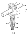
- FIG. 13 is a perspective view of another embodiment of a polyaxial pedicle screw with a rod member secured thereto with a set screw in accordance with the present disclosure
- FIG. 14 is an exploded, perspective view of yet another embodiment of a polyaxial pedicle screw in accordance with the present disclosure.
- FIG. 15 is an enlarged, perspective view of an anvil of the polyaxial pedicle screw shown in FIG. 14 ;
- FIGS. 16-17 are progressive perspective views illustrating assembly steps of the polyaxial pedicle screw of FIG. 14 in accordance with the present disclosure
- FIG. 18 is an exploded, perspective view of yet another embodiment of a polyaxial pedicle screw in accordance with the present disclosure.
- FIG. 19 is a perspective view of first and second wedge members of the polyaxial pedicle screw shown in FIG. 18 ;
- FIG. 20 is top view of the first and second wedge members shown in FIG. 19 ;
- FIG. 21 is a cross-sectional view of the polyaxial pedicle screw in an assembled configuration
- FIG. 22 is an exploded perspective view of another embodiment of a polyaxial pedicle screw in accordance with the present disclosure.
- FIG. 23 is an enlarged cross-sectional view of the indicated area of detail shown in FIG. 2 ;
- FIG. 24 illustrates various thread forms of embodiments of the presently disclosed polyaxial pedicle screw
- FIG. 25 is a perspective view, with parts separated, of a rod reducer in accordance with the present disclosure.
- FIG. 26A is a cross-sectional view of the rod reducer of FIG. 25 ;
- FIG. 26B is an enlarged cross-sectional view of the indicated area of detail shown in FIG. 26A ;
- FIG. 27 is a perspective view, with parts separated, of an outer member of the rod reducer shown in FIG. 25 ;
- FIG. 28 is a cross-sectional view of the outer member of FIG. 27 ;
- FIGS. 29A-29C are progressive perspective views illustrating a reduction of a rod into an embodiment of the presently disclosed pedicle screw with the rod reducer shown in FIG. 25 ;
- FIG. 30 is a perspective view of a handle and rod reducer assembly in accordance with the present disclosure.
- FIG. 31 is a perspective view, with parts separated, of the handle and rod reducer assembly of FIG. 30 .
- proximal and distal may be employed interchangeably, and should be understood as referring to the portion of a structure that is closer to a clinician during proper use.
- distal and “leading” may also be employed interchangeably, and should be understood as referring to the portion of a structure that is farther from the clinician during proper use.
- cephalad or “cranial” is used in this application to indicate a direction toward a patient's head, whereas the term “caudad” indicates a direction toward the patient's feet.
- the term “medial” indicates a direction toward the middle of the body of the patient
- the term “lateral” indicates a direction toward a side of the body of the patient (i.e., away from the middle of the body of the patient).
- the term “posterior” indicates a direction toward the patient's back
- the term “anterior” indicates a direction toward the patient's front.
- the present disclosure is directed to a polyaxial pedicle (multi-planar) screw that can provide a connection, via a spinal rod, between adjacent vertebrae not in the same plane.
- a polyaxial pedicle screw is generally referred to as 100 .
- the polyaxial pedicle screw 100 includes a housing 110 , a compression ring or cap 120 , an anvil 130 , a bone screw member 140 , and a set screw 150 ( FIG. 8 ).
- the housing 110 defines an opening 112 therethrough that permits the reception of any suitable driving instrument (not shown) therethrough.
- the housing includes opposing walls 110 a , 110 b that define a U-shaped channel 111 therebetween.
- Each opposing wall 110 a , 110 b includes an external flanged recess 113 that is configured to facilitate grasping of the housing 110 by an instrument (not shown) that can also be used to facilitate insertion of the pedicle screw 100 into a pedicle of a vertebral body.
- the internal surfaces of opposing walls 110 a , 110 b include threaded portions 115 that are threadably engagable with external threads 152 of the set screw 150 ( FIG. 8 ) to facilitate the securement of a rod member 160 (see FIGS. 12 and 13 ) within the channel 111 of the housing 110 adjacent the anvil 130 .
- the housing 110 includes a collar 114 extending therefrom.
- the collar 114 may have a smaller diameter than the diameter defined by the opposing walls 110 a , 110 b of the housing 110 .
- the collar 114 is adapted to facilitate the securement of the compression ring or cap 120 to the housing 110 once the bone screw member 140 is secured to the housing 110 .
- the collar 114 has a cut out 114 a that provides a recess for the reception of a portion of the bone screw member 140 , namely a neck 146 of the bone screw member 140 .
- the cut out 114 a facilitates the positioning of the bone screw member 140 within the housing 110 from a distal end of the housing 110 .
- the bone screw member 140 when the bone screw member 140 is positioned perpendicular (or substantially perpendicular; see e.g., FIG. 16 ) to the opening 112 (e.g., positioned within a longitudinal axis “L” of the pedicle screw 100 ⁇ see FIG. 1 ⁇ and in axial alignment with a transverse axis “B” extending through cut out 114 a ⁇ see FIG. 5 ⁇ such that a longitudinal axis “C” of the bone screw member 140 ⁇ see FIG.
- the head 142 by virtue of a smaller dimensioned cylindrically shaped first portion 142 a of the head 142 , slides into the housing 110 .
- a larger dimensioned spherically shaped second portion 142 b of the head 142 maintains the bone screw member 140 within the housing 110 .
- the bone screw member 140 includes a head 142 and a threaded shaft 144 extending from the head 142 .
- the bone screw member 140 may be a self-starting fastener or self-tapping fastener.
- the head 142 is selectively securable within the housing 110 and includes a first portion 142 a and a second portion 142 b .
- the head 142 includes a driving recess 142 c , which may be hexalobular or any other suitable configuration, defined in a proximal surface of the head 142 .
- the driving recess 142 c is engagable with any suitable driving instrument (not shown) to enable the driving instrument to advance the bone screw member 140 within bone.
- the first portion 142 a which may have substantially cylindrical surfaces (but any suitable shape is contemplated), enables the head 142 to fit through the opening 112 defined in the housing 110 from the distal end of the housing 110 .
- opposed cylindrical surfaces of the first portion 142 a may be positioned in co-axial alignment transverse to axis “A” (simultaneously, the opposed spherical surfaces of the second portion 142 b are coaxial with axis “A”; see FIG.
- the second portion 142 b which may have substantially spherical surfaces (but any suitable shape is contemplated), maintains the head 142 of the bone screw member 140 within the housing 110 once the head 142 is fully inserted from the distal end of the housing 110 as discussed above.
- the effective diameter of the first portion 142 a e.g., the cylindrical section of the screw head 142
- the diameter of the second portion 142 b e.g., the spherical section of the screw head 142
- the diameter of the second portion 142 b is dimensioned to be larger than the diameter of the distal opening 112 of the housing 110 , so that when the screw head 142 is disposed within the housing 110 and the cylindrical section is not aligned with the distal opening 112 , the diameter of the spherical section prevents the screw head 142 from exiting the housing 110 through the distal opening 112 .
- the compression ring or cap 120 may be slid over the shaft 144 and affixed (such as by friction, threading, bayonet mount, gluing, ultrasonic or other welding or the like) to the collar 114 of the housing 110 to further secure the bone screw member 140 to the housing 110 .
- the bone screw member 140 is selectively positionable at plurality of angles relative to the housing 110 when engaged to the housing 110 .
- the bone screw member 140 may be fixedly securable relative to the housing 110 at a cone angle ⁇ in the range of 60 to 80 degrees, preferably 70 degrees, from the longitudinal axis “L” extending through the polyaxial pedicle screw 100 .
- the compression ring or cap 120 may be securable to the collar 114 to cover the cut out 114 a after the head 142 of the bone screw member 140 is positioned within the housing 110 to prevent the bone screw member 140 from re-orienting to a position in which the first portion 142 a , namely the cylindrical surfaces, of the head 142 of the bone screw member 140 is aligned with the opening 112 of the housing 110 .
- the bone screw member 140 when the bone screw member 140 is positioned within cut out 114 a of collar as discussed above, the bone screw member 140 is positioned transverse to the opening 112 and may be oriented with the cylindrical section aligned with the distal housing opening 112 such that the screw head 142 is movable into the housing 110 without inhibition from the second portion 142 b , which, as discussed above, otherwise maintains the bone screw member 140 within the housing 110 once the screw head 142 is disposed inside the housing 110 .
- the compression ring or cap 120 covers the cut out 114 a portion of the collar 114 so the shaft 144 of the bone screw member 140 cannot be re-oriented to a position in which the first portion 142 a , namely the cylindrical surfaces, of the head 142 are co-axial with the opening 112 of the housing 110 .
- the anvil 130 is positionable within the housing 110 adjacent the head 142 of the bone screw member 140 when the anvil 130 and the head 142 of the bone screw member 140 are positioned within the housing 110 to facilitate the securement of a rod member 160 (see FIGS. 12-13 ) within the housing 110 .
- the set screw 150 is positionable within the housing 110 , e.g., via threading engagement, to secure the rod member 160 within the housing 110 adjacent the anvil 130 .
- the set screw 150 may be formed of titanium or titanium alloy.
- the set screw 150 includes a driving interface 154 that is engagable with any suitable driving instrument to threadably engage the set screw 150 within the housing 110 .
- the anvil 130 includes a body 132 defining a passage 134 which permits the reception of a driving instrument therethrough.
- the passage 134 includes a top portion 134 a and a bottom portion 134 b separated by an edge 134 c .
- the bottom portion 134 b includes arcuate surfaces 135 to accommodate spherical movement of the head 142 of the bone screw 140 when positioned therein.
- the body 132 also defines an arcuate cavity 136 at a proximal end thereof for the reception of a rod member 160 ( FIG. 12 ) which will be described in greater detail below.
- the body 132 defines one or more grooves 138 a in an outer surface 132 a of the anvil 130 .
- Each groove 138 a defines one or more flaps 138 b .
- the anvil 130 may include a pair of opposing flaps 138 b that act as cantilever beam springs.
- the one or more flaps 138 b are flexibly attached to the anvil 130 adjacent the cavity 136 to enable the anvil 130 to flex an amount sufficient to maintain the head 142 of the bone screw member 140 in constant contact with the anvil 130 when the bone screw member 140 is moved relative to the anvil 130 .
- the one or more flaps 138 b provide sufficient resistance (against inner surfaces of the housing 20 ) to prevent any laxity or unintended movement between the anvil 130 and the head 142 of the bone screw member 140 .
- the spring force provided by the flaps 138 b creates friction between the bone screw member 140 and the housing 110 , thus stabilizing the assembly and making it easier to introduce a rod member 160 .
- the cavity 136 has a surface 137 with a plurality of radii of curvature to accommodate variously sized rod members 160 .
- a first rod member 160 a having a first diameter is shown positioned in the cavity 136 ; in comparison, a second rod member 160 b having a second diameter is also shown positioned in the cavity 136 .
- first rod member 160 a is placed against the arcuate surfaces of the anvil 130 , the first rod member 10 a nests easily against the anvil 130 because the first rod member 160 a closely corresponds to the arc of the arcuate surfaces of the anvil 130 .
- the second rod member 160 b When the second rod member 160 b , a larger diameter rod, is positioned against the arcuate surfaces of the anvil 130 and the set screw 150 is tightened against the second rod member 160 b , the second rod member 160 b is similarly nested in the arcuate surfaces of the anvil 130 but is seated slightly more prominently.
- two rod diameters are shown in FIG. 12 for illustrative purposes only, and in practice only one rod at a time could be placed in the housing.
- the surface 137 of the cavity 136 defines a first section 137 a with a first radius of curvature, a second section 137 b with a second radius of curvature, and a third section 137 c with a third radius of curvature.
- the plurality of radii of curvature defines a compound curve that provides two or more lines of contact on a plurality of different diameter rod members 160 (e.g., rod members 160 a , 160 b ) without creating a stress riser in the anvil 130 when any one of a plurality of different diameter rod members 160 is positioned adjacent the compound curve.
- the outer surface 132 a of the anvil 130 may have a non-round shape, e.g., slightly elliptical, to prevent disorientation of the anvil 130 when positioning the rod member 160 adjacent the anvil 130 .
- the bone screw member is fastenable to a bone structure (e.g. vertebra) and the housing 110 is repositionable in a plurality of directions with respect to the bone screw member 140 as discussed above.
- the housing 110 is rotatable about the longitudinal axis “L” (see FIGS. 1 and 3 ) extending through the polyaxial pedicle screw 100 as well as pivotable relative to the longitudinal axis “L” and the bone screw member 140 .
- a rod member 160 e.g., a spinal rod, is positionable in the U-shaped channel 111 of the housing 110 and is nested against the arcuate surfaces of the anvil 130 as discussed above.
- the rod member 160 is then secured to the polyaxial pedicle screw 100 using a set screw 150 ( FIG. 8 ).
- the set screw 150 is inserted into a proximal side of opening 112 of the housing 20 adjacent the opposing walls 110 a , 110 b and rotated such that a distal end of the set screw 150 contacts the surface of the rod member 160 and drives the rod member 160 and the anvil 130 towards the head 142 of the bone screw member 140 .
- the set screw 150 is tightened further, which compresses the rod member 160 , the anvil 130 , and the head 142 of the bone screw member 140 within a recess 117 of the housing 110 .
- the frictional engagement between the head 142 of the bone screw member 140 and the bottom portion 134 b of the anvil 130 fixes the angular relationship between the housing 110 and the bone screw member 140 .
- Polyaxial pedicle screw 200 is substantially similar to polyaxial pedicle screw 100 and is only described herein to the extent necessary to describe the differences in construction and operation thereof.
- Polyaxial pedicle screw 200 includes a housing 210 , a bone screw member 140 , an anvil 230 , and a compression ring or cap 120 .
- the housing 210 has one or more slots 212 defined on an inner surface 216 of the housing 210 .
- the slots 212 may extend continuously and/or discontinuously along opposing walls 210 a and 210 b and/or along a collar 214 .
- the anvil 230 includes one or more flaps 236 , one or more grooves 238 , and one or more protuberances 234 on an outer surface 232 of the anvil 230 .
- flaps 236 are movable in response to an applied pressure.
- the protuberances 234 and the slots 212 are engagable to maintain the alignment of the anvil 230 with respect to the housing 210 when the anvil 230 is positioned within the housing 210 .
- an aligned or substantially aligned arrangement of the anvil 230 with respect to the housing 210 maintains the U-shaped channel 111 in a position to receive a rod member 160 that is aligned with the polyaxial pedicle screw 200 .
- the flaps 236 and grooves 238 may be aligned or substantially aligned with the protuberances 234 .
- polyaxial pedicle screw 300 is substantial similar to polyaxial pedicle screws 100 , 200 and is only described herein to the extent necessary to describe the differences in construction and operation thereof.
- Polyaxial pedicle screw 300 includes a housing 210 , a bone screw member 340 , an anvil 230 (see FIG. 11 ), and a compression ring or cap 120 .
- bone screw member 340 includes a head 142 (see FIG. 2 ) and a threaded shaft 344 .
- the threaded shaft 344 includes a first threaded segment 344 a and a second threaded segment 344 b.
- polyaxial pedicle screw 400 is substantial similar to polyaxial pedicle screws 100 , 200 , 300 and is only described herein to the extent necessary to describe the differences in construction and operation thereof.
- Polyaxial pedicle screw 400 includes a housing 210 , a bone screw member 440 , an anvil 430 , and a compression ring or cap 120 .
- Bone screw member 440 includes a head 442 and a threaded shaft 444 .
- the head 442 includes a first portion 442 a and a second portion 442 b .
- the second portion 442 b includes surface texture 443 , e.g., serrations, to facilitate the frictional engagement with the anvil 430 and/or the housing 210 such that a user is required to apply some minimal force to move the bone screw member 440 relative to the anvil 430 and/or the housing 210 .
- the bone screw member 440 frictionally engages with the anvil 430 such that a user applied force (e.g., beyond gravity forces) is necessary to reposition the bone screw member 440 relative to the anvil 430 when the bone screw member 440 is disposed in engagement with the anvil 430 .
- the anvil 430 includes a body 432 .
- the body 432 includes a pair of opposing grooves 434 , a pair of opposing flaps 436 , and a pair of opposing protuberances 438 .
- the body 432 also defines a pair of notches 435 that extend along each protuberance 438 .
- the opposing flaps 436 each include a protuberance 436 a positioned between a pair of notches 436 b .
- the protuberance 436 a and pair of notches 436 b may be aligned or substantially aligned with protuberances 438 and pair of notches 435 , respectively, as illustrated in FIG. 15 .
- Polyaxial pedicle screw 500 is substantially similar to polyaxial pedicle screws 100 , 200 , 300 , 400 and is only described herein to the extent necessary to describe the differences in construction and operation thereof.
- Polyaxial pedicle screw 500 includes a housing 510 , a compression ring or cap 520 , an anvil 530 , a bone screw member 540 , and one or more pins 550 .
- the housing 510 is positionable on a head 542 of the bone screw member 540 .
- the housing 510 defines one or more pin channels 512 therethrough for the reception of a pin 550 to secure at least a portion of the anvil 530 within the housing 510 .
- the anvil 530 includes a first wedge member 532 and a second wedge member 534 .
- the first and second wedge members 532 , 534 are separate and distinct sections of the anvil 530 , as most clearly illustrated in FIG. 20 .
- Each wedge member 532 , 534 is positionable within the housing 510 adjacent the head 542 to facilitate the securement of the head 542 of the bone screw member 540 and a rod member 160 (see FIG. 13 ) within the housing 510 .
- Each wedge member 532 , 534 defines one or more pin pockets 536 in an outer surface 535 thereof.
- a pin 550 is positionable within the one of the pin channels 512 and one of the pin pockets 536 to maintain one of the first and second wedge members 532 , 534 within the housing 510 , as best illustrated in FIG. 21 .
- the head 542 of the bone screw member 540 need not be configured to have both cylindrical and spherical shaped sections, and the entire head 542 can be substantially spherical.
- each wedge 532 , 534 is disposed within the housing 510 in its proximal-most position, such that the spherical head 542 may enter a bottom opening 514 of the housing 510 unimpeded. Once the head 542 is inserted, the wedges 532 , 534 drop from their proximal position to embrace the head 542 and prevent the head 542 from being withdrawn from the housing 510 .
- a kit of the presently disclosed polyaxial pedicle screws may include two or more polyaxial pedicle screws of the present disclosure and one or more rod members 160 .
- any portion of any of the presently disclosed polyaxial pedicle screws can be formed of formed of titanium, titanium alloy, stainless steel, cobalt chrome, or other metal or polymeric materials.
- the housing could be made of a harder or stiffer material such as cobalt chrome, while the screw and anvil and set screw may be made of another, compatible material such as titanium or titanium alloy.
- components of any of the presently disclosed embodiments may be press fit, staked, pinned, or welded together.
- any embodiments of the bone screw members presently disclosed pedicle screws may have a single lead thread or a double lead thread (e.g., two starts) to facilitate insertion into and fixation within bone.
- a pair of helical threads may be offset by 180 degrees so that the lead of threads is approximately equal to double the pitch of the threads.
- the axial distance that bone screw members with a double lead thread configuration travel during one full 360 degree rotation is approximately double the distance between adjacent crests of the threads.
- the lead may be in the range of about 1 mm to about 3 mm, preferably about 2 mm, while the pitch of each of the threads may be in the range of about 2 mm to about 6 mm, preferably about 4 mm.
- a distal segment of the shaft of a bone screw member may taper distally to a distal tip of the shaft.
- both the inner and outer diameters of the shaft of the bone screw member may taper distally, e.g., the shaft and the threads may taper distally.
- any embodiments of the bone screw members of the presently disclosed pedicle screws may be provided in any suitable diameter size and/or length.
- Some of the bone screw members may have diameters of approximately 4.5, 5.5, 6.5, 7.5, 8.5, 9.5, and 10.5 mm and may have lengths of approximately 25-115 mm.
- the thread dimensions on a 6.5 mm diameter bone screw member may include a major diameter of about 0.256 inches and a minor diameter of about 0.177 inches through the proximal or trailing two-thirds (2 ⁇ 3) of the screw length. As shown in FIGS.
- the distal or leading third (1 ⁇ 3) of the length of the shaft which is the distal portion of the bone screw member, may taper, for example, to about a 0.150 inches major diameter at the distal tip of the distal third of the length of the shaft.
- This taper may follow a radius of about 3.582 inches for a 6.5 mm diameter and 45 mm length screw. This radius is defined by the tip diameter as well as its tangency with the major diameter at the start of the taper. Therefore, the radius varies by diameter and length of the bone screw member.
- any embodiments of the bone screw members of the presently disclosed pedicle screws may have a buttress thread form arrangement that has improved pullout strength as compared to competitive products (see Tables 1 and 2, below).
- Various thread form arrangements of embodiments of the presently disclosed pedicle screws are illustrated in FIG. 24 .
- polyaxial pedicle screw 600 is generally referred to as 600 .
- Polyaxial pedicle screw 600 is substantially similar to polyaxial pedicle screw 100 and is only described herein to the extent necessary to describe the differences in construction and operation thereof.
- Polyaxial pedicle screw 600 includes a housing 210 , a bone screw member 620 , an anvil 430 , and a compression ring or cap 120 .
- bone screw member 620 of pedicle screw 600 includes a buttress thread form that is arranged so that a pressure flank 622 of the buttress thread form is disposed at an angle gamma “ ⁇ ” relative to the thread or shaft axis “L” extending between leading and trailing ends of shaft 621 (e.g., the angle defined between shaft axis “L” and line “e”) of bone screw member 620 .
- Angle gamma “ ⁇ ” may be nearly perpendicular, for example, approximately 95 degrees, so that the radial component of the thrust taken by the pressure flank 622 during pullout is reduced to a minimum to increase the pullout strength of the screw.
- the thread may have a leading edge 624 that extends at an angle delta “ ⁇ ” relative to vertical (i.e., line “d” which is an orientation that is perpendicular to a shaft axis “L”). Angle delta “ ⁇ ”, which extends between lines “c” and “d”, may be about 45 degrees. A trailing edge 626 of the thread is disposed at an angle beta “ ⁇ ” relative to vertical. Angle beta “ ⁇ ”, which extends between line “d” (vertical) and line “e”, may be about ⁇ 5 degrees.
- leading and trailing ends 624 , 626 define an angle alpha “ ⁇ ” therebetween that is equal to angle delta “ ⁇ ” plus angle beta “ ⁇ .”
- the width of the crest 628 may be about 0.007 inches.
- the pullout strength of various pedicle screws were tested in a 10 lb/ft 3 foam and a 20 lb/ft 3 foam.
- the data provided in Tables 1 and 2 indicate statistically significant differences among the pedicle screws.
- the pedicle screws tested included pedicle screw 600 , a taper lock screw as shown and disclosed in application Ser. No. 12/739,461 filed on Apr. 23, 2010, which is incorporated herein by reference, a set screw as shown and disclosed in application Ser. No. 12/739,506, filed on Apr. 23, 2010, which is incorporated herein by reference, and competitor screws 1-9.
- testing results collected from the 20 lb/ft 3 are displayed in Table 2 below.
- the mean peak load values are substantially higher than those found in Table 1. Values typically range from 900-1200N, again well within the values of the standard. Note that the ranking of the screws has changed due to the fact that the test was run using (simulated) denser bone which is more indicative of the bone in the pedicle of a healthy patient.
- the features of the threaded buttress form arrangement and the tapering of both the major and minor diameter of bone screw member 620 provide an increase in pullout strength of the pedicle screw 600 .
- the thread of the leading third of the bone screw member 620 creates an initial pathway while being inserted.
- the thread of the trailing two-thirds of the bone screw member 620 creates a new pathway in the bone that is larger in diameter than the initial pathway to achieve greater bone purchase.
- the tapered shape of the leading third of the bone screw member 620 helps to wedge the bone screw member 620 into position within the bone while increasing the pullout strength.
- the thread may include a cutting flute that may be coincident with the distal tip of the screw to aid with insertion by making it easier to penetrate the bone and clear a pathway for trailing portions of the bone screw member 620 .
- the cutting flute may be 0.025 inches wide with a 0.50 inch radius that is centered 0.525 inches off of the center axis (e.g., off of the thread or shank axis).
- the pitch of the thread of the bone screw member 620 provides an optimal balance between limiting the amount of torque required to insert the bone screw member 620 into bone and facilitating the manufacturing efficiencies necessary to optimize the performance of the screw.
- the pitch of the thread of the bone screw member 620 may be 0.079 inches (2 mm).
- the bone screw member 620 may have a double lead thread with the lead being 0.157 inches (4 mm) to aid in reducing the number of rotations it requires to insert the screw.
- a rod reducer 700 includes an outer member 710 , an inner member 720 , and a pair of gripping members 730 .
- Outer member 710 includes a proximal segment 712 , a distal segment 714 , and a ring member 716 that is disposed between proximal and distal segments 712 , 714 .
- Proximal segment 712 includes an engaging portion 712 a at a distal end of proximal segment 712 and a gripping portion 712 b at a proximal end of proximal segment 712 .
- An inner surface 712 c of proximal segment 712 is threaded.
- Distal segment 714 defines a slot 714 c therethrough and includes a reducing portion 714 a at a distal end of distal segment 714 and a receiving portion 714 d at a proximal end of distal segment 714 .
- Receiving portion 714 d includes a plurality of gripping features 715 on an outer surface of receiving portion 714 d .
- a pair of rod engaging slots 714 b and a pair of gripping member receiving slots 714 e are defined through reducing portion 714 a .
- Receiving portion 714 d of distal segment 714 is configured to receive engaging portion 712 a of proximal segment 712 so that ring member 716 is disposed between proximal and distal segments 712 , 714 .
- the components of outer member 710 may be integrally formed or assembled.
- Inner member 720 includes an elongate body member 722 that defines an annular recess 728 configured to receive the pair of gripping members 730 so that the gripping members 730 are disposed in opposition on the elongate body member 722 .
- Inner member 720 member 722 includes a pair of arms 726 supported on a distal end of elongate body member 722 .
- a proximal end of elongate body member 722 has a threaded arrangement 724 that mates with threaded inner surface 712 c of proximal segment 712 of outer member 712 to axially advance outer member 712 relative to inner member 720 as will be described in greater detail below.
- Each gripping member 730 includes a body 732 having a supporting member 734 , a proximal finger 738 , and a distal finger 736 .
- Supporting member 734 is configured to engage annular recess 728 of inner member 720 to support body 732 of each gripping member 730 on inner member 720 .
- Proximal finger 738 extends proximally from supporting member 734 and is slidably positionable within slot 714 c of outer member 710 .
- Distal finger 736 extends distally from supporting member 734 and is positionable between an arm 726 of inner member 720 and reducing portion 714 a of outer member 710 so that distal finger 736 is substantially aligned with a gripping member receiving slot 714 e of reducing portion 714 a.
- distal fingers 736 of gripping member 730 of rod reducer 700 are secured to an outer surface of an embodiment of a polyaxial pedicle screw, for example, polyaxial pedicle screw 900 .
- Proximal segment 712 of outer member 710 may then be rotated by virtue of the threaded arrangement between outer member 710 and inner member 720 to axially advance distal segment 714 of outer member 710 relative to inner member 720 and proximal segment 712 .
- Proximal segment 712 remains axially fixed when rotated.
- proximal segment 712 rotates, distal segment 714 remains radially fixed as distal segment 714 axially translates relative to inner member 720 and proximal segment 712 .
- Outer member 710 approximates a spinal rod 800 positioned between rod reducer 700 and pedicle screw 900 as outer member 710 is advanced toward pedicle screw 900 to secure spinal rod 800 within a saddle of pedicle screw 900 .
- a proximal end of slot 714 c of outer member 710 approximates a proximal end of proximal fingers 738 of gripping member 730 .
- a rod reducer and handle assembly 1000 includes the rod reducer 700 and a handle assembly 1002 .
- Handle assembly 1002 includes a turning handle 1200 and an anti-torque handle 1100 that are selectively connectable to gripping portion 712 b of rod reducer 700 .
- Turning handle 1200 includes a shaft 1210 , a handle 1220 , and a socket 1230 that defines an opening 1232 . Opening 1232 is configured to receive a proximal end of gripping portion 712 b of rod reducer 700 .
- Handle 1220 is secured to a proximal end of shaft 1210 and socket 1230 is secured to a distal end of shaft 1210 .
- Anti-torque handle 1100 includes a shaft 1120 and a handle 1110 that may be integrally formed.
- Shaft 1120 includes a socket 1122 that defines an opening 1122 a at a distal end of socket 112 .
- Opening 1122 a is disposed in communication with a lumen 1125 defined within shaft 1120 and another opening 1124 disposed at a proximal end of shaft 1120 so that anti-torque handle 1100 may slide over gripping portion 712 b of rod reducer 700 and engage with gripping feature 715 of rod reducer 700 to prevent rotational movement of distal segment 714 of outer member 714 of rod reducer 700 .
- either or both turning handle 1200 and anti-torque handle 1100 may be used to facilitate the rotational movement of outer member 710 relative to inner member 720 .
- rotation of turning handle 1200 imparts rotational movement to proximal segment 712 of outer member 710
- anti-torque handle 1100 imparts counter rotational movement to distal segment 714 of outer member 710 so that proximal segment 712 rotates and distal segment 714 axially translates without rotating.
- anti-torque handle 1100 is configured to limit the amount of torque imparted from the rotational movement imparted by turning handle 1200 to prevent undesirable torquing of the outer member 710 .
- anti-torque handle 1100 slides down over the outer surface of outer member 710 of rod reducer 700 so that a distal end of anti-torque handle 1100 engages distal segment 714 of outer member 710 and a proximal end of proximal segment 712 of outer member 710 is exposed for engagement with turning handle 1200 .
- gripping member 730 is secured within annular recess 728 of inner member 720 such that proximal finger 738 of gripping member 730 is supported in slot 714 c of distal segment 714 of outer member 710 , the engagement of anti-torque handle 1110 with gripping feature 715 of distal segment 714 of outer member 710 prevents rotation of both distal segment 714 of outer member 710 and inner member 720 as proximal segment 712 of outer member 710 is rotated with turning handle 1200 .
- pedicle screw 900 After spinal rod 800 is fully reduced into the saddle of one of the presently disclosed pedicle screws, for example, pedicle screw 900 , turning handle 1200 and anti-torque handle 1100 may be removed and a set screw may be inserted down an inner diameter of rod reducer 700 to lock spinal rod 800 into place.
- anti-torque handle 1100 may also be used to prevent rotation when tightening the set screw after spinal rod 800 has been fully reduced. Rod reducer 700 may then be removed.
Abstract
Description
| TABLE 1 |
| Variation in overall pullout strength of all tested screws in 10 lb/ft3 foam. |
| (n = 30 for all pedicle screws) |
| (all pedicle screws inserted to 20 mm depth) |
| Pedicle Screw | OD | Mean (N) | SD (N) | ||
| |
6.5 | 343.80 | 21.21 | ||
| |
6.5 | 313.59 | 17.38 | ||
| Taper Lock Screw | 6.5 | 306.61 | 21.37 | ||
| Competitor 2 | 7.0 | 296.97 | 19.23 | ||
| Competitor 3 | 6.0 | 291.84 | 12.72 | ||
| Set Screw | 6.5 | 291.50 | 16.94 | ||
| Competitor 4 | 6.5 | 290.68 | 9.87 | ||
| |
6.5 | 265.67 | 20.58 | ||
| Competitor 6 | 6.5 | 253.96 | 22.47 | ||
| Competitor 7 | 5.5 | 203.45 | 9.91 | ||
| Competitor 8 | 5.0 | 177.78 | 5.93 | ||
| Competitor 9 | 5.5 | 163.71 | 11.28 | ||
| TABLE 2 |
| Variation in overall pullout strength of all tested screws in 20 lb/ft3 foam. |
| (n = 30 for all pedicle screws) |
| (all pedicle screws inserted to 20 mm depth) |
| Pedicle Screw | OD | Mean (N) | SD (N) | ||
| |
6.5 | 1180.90 | 82.88 | ||
| |
6.5 | 1042.87 | 40.80 | ||
| Competitor 2 | 7.0 | 1017.28 | 54.66 | ||
| Taper Lock Screw | 6.5 | 957.64 | 33.22 | ||
| Set Screw | 6.5 | 949.76 | 53.00 | ||
| Competitor 6 | 6.5 | 943.47 | 35.20 | ||
| Competitor 3 | 6.0 | 930.99 | 27.68 | ||
| Competitor 4 | 6.5 | 898.75 | 33.12 | ||
| |
6.5 | 892.01 | 38.46 | ||
| Competitor 7 | 5.5 | 649.65 | 22.11 | ||
| Competitor 8 | 5.0 | 578.48 | 16.71 | ||
| Competitor 9 | 5.5 | 571.37 | 12.82 | ||
Claims (17)
Priority Applications (6)
| Application Number | Priority Date | Filing Date | Title |
|---|---|---|---|
| US13/595,533 US9393049B2 (en) | 2010-08-20 | 2012-08-27 | Spinal fixation system |
| AU2013201293A AU2013201293B2 (en) | 2010-08-20 | 2013-03-06 | Spinal Fixation System |
| US15/210,448 US9924973B2 (en) | 2010-08-20 | 2016-07-14 | Spinal fixation system |
| US15/905,012 US10499957B2 (en) | 2010-08-20 | 2018-02-26 | Spinal fixation system |
| US16/686,703 US11612417B2 (en) | 2010-08-20 | 2019-11-18 | Spinal fixation system |
| US18/125,490 US20230338064A1 (en) | 2010-08-20 | 2023-03-23 | Spinal Fixation System |
Applications Claiming Priority (4)
| Application Number | Priority Date | Filing Date | Title |
|---|---|---|---|
| US37535410P | 2010-08-20 | 2010-08-20 | |
| US13/214,331 US8882817B2 (en) | 2010-08-20 | 2011-08-22 | Spinal fixation system |
| US201161527632P | 2011-08-26 | 2011-08-26 | |
| US13/595,533 US9393049B2 (en) | 2010-08-20 | 2012-08-27 | Spinal fixation system |
Related Parent Applications (1)
| Application Number | Title | Priority Date | Filing Date |
|---|---|---|---|
| US13/214,331 Continuation-In-Part US8882817B2 (en) | 2010-08-20 | 2011-08-22 | Spinal fixation system |
Related Child Applications (1)
| Application Number | Title | Priority Date | Filing Date |
|---|---|---|---|
| US15/210,448 Division US9924973B2 (en) | 2010-08-20 | 2016-07-14 | Spinal fixation system |
Publications (2)
| Publication Number | Publication Date |
|---|---|
| US20130046345A1 US20130046345A1 (en) | 2013-02-21 |
| US9393049B2 true US9393049B2 (en) | 2016-07-19 |
Family
ID=47713186
Family Applications (5)
| Application Number | Title | Priority Date | Filing Date |
|---|---|---|---|
| US13/595,533 Active 2031-12-07 US9393049B2 (en) | 2010-08-20 | 2012-08-27 | Spinal fixation system |
| US15/210,448 Active US9924973B2 (en) | 2010-08-20 | 2016-07-14 | Spinal fixation system |
| US15/905,012 Active US10499957B2 (en) | 2010-08-20 | 2018-02-26 | Spinal fixation system |
| US16/686,703 Active 2033-05-24 US11612417B2 (en) | 2010-08-20 | 2019-11-18 | Spinal fixation system |
| US18/125,490 Pending US20230338064A1 (en) | 2010-08-20 | 2023-03-23 | Spinal Fixation System |
Family Applications After (4)
| Application Number | Title | Priority Date | Filing Date |
|---|---|---|---|
| US15/210,448 Active US9924973B2 (en) | 2010-08-20 | 2016-07-14 | Spinal fixation system |
| US15/905,012 Active US10499957B2 (en) | 2010-08-20 | 2018-02-26 | Spinal fixation system |
| US16/686,703 Active 2033-05-24 US11612417B2 (en) | 2010-08-20 | 2019-11-18 | Spinal fixation system |
| US18/125,490 Pending US20230338064A1 (en) | 2010-08-20 | 2023-03-23 | Spinal Fixation System |
Country Status (1)
| Country | Link |
|---|---|
| US (5) | US9393049B2 (en) |
Cited By (11)
| Publication number | Priority date | Publication date | Assignee | Title |
|---|---|---|---|---|
| US9597121B2 (en) | 2012-01-30 | 2017-03-21 | Biedermann Technologies Gmbh & Co. Kg | Bone anchoring device |
| US9924973B2 (en) | 2010-08-20 | 2018-03-27 | K2M, Inc. | Spinal fixation system |
| US20180132911A1 (en) * | 2015-05-12 | 2018-05-17 | Shandong Weigao Orthopedic Device Company Ltd | Grasping end of frog-style forceps |
| US10076362B2 (en) | 2012-07-18 | 2018-09-18 | Biedermann Technologies Gmbh & Co. Kg | Polyaxial bone anchoring device |
| WO2018183314A1 (en) | 2017-03-30 | 2018-10-04 | K2M, Inc. | Bone anchor apparatus and method of use thereof |
| WO2019010479A1 (en) | 2017-07-07 | 2019-01-10 | K2M, Inc. | Surgical implant and methods of addictive manufacturing |
| EP3563784A1 (en) | 2018-05-03 | 2019-11-06 | K2M, Inc. | Head to head transverse connector |
| US10905484B2 (en) | 2016-02-18 | 2021-02-02 | K2M, Inc. | Surgical fixation assemblies and methods of use |
| US11517361B2 (en) | 2017-03-30 | 2022-12-06 | K2M, Inc. | Fixation device and method of using the same |
| US11918262B2 (en) | 2017-03-30 | 2024-03-05 | K2M, Inc. | Fixation device and method of using the same |
| US11963698B2 (en) | 2012-07-18 | 2024-04-23 | Biedermann Technologies Gmbh & Co. Kg | Polyaxial bone anchoring device |
Families Citing this family (52)
| Publication number | Priority date | Publication date | Assignee | Title |
|---|---|---|---|---|
| US9980753B2 (en) * | 2009-06-15 | 2018-05-29 | Roger P Jackson | pivotal anchor with snap-in-place insert having rotation blocking extensions |
| US8444681B2 (en) | 2009-06-15 | 2013-05-21 | Roger P. Jackson | Polyaxial bone anchor with pop-on shank, friction fit retainer and winged insert |
| US8328806B2 (en) * | 2008-06-24 | 2012-12-11 | Extremity Medical, Llc | Fixation system, an intramedullary fixation assembly and method of use |
| US8313487B2 (en) * | 2008-06-24 | 2012-11-20 | Extremity Medical Llc | Fixation system, an intramedullary fixation assembly and method of use |
| JP2012529969A (en) | 2008-08-01 | 2012-11-29 | ロジャー・ピー・ジャクソン | Longitudinal connecting member with tensioning cord with sleeve |
| EP2757988A4 (en) | 2009-06-15 | 2015-08-19 | Jackson Roger P | Polyaxial bone anchor with pop-on shank and winged insert with friction fit compressive collet |
| CN103917181A (en) | 2009-06-15 | 2014-07-09 | 罗杰.P.杰克逊 | Polyaxial bone anchor with pop-on shank and friction fit retainer with low profile edge lock |
| US8545505B2 (en) * | 2010-01-15 | 2013-10-01 | Pioneer Surgical Technology, Inc. | Low friction rod persuader |
| US9393048B2 (en) * | 2010-02-23 | 2016-07-19 | K2M, Inc. | Polyaxial bonescrew assembly |
| DE112011103644T5 (en) | 2010-11-02 | 2013-12-24 | Roger P. Jackson | Polyaxial bone anchor with quick-release shaft and rotatable holder |
| US8337530B2 (en) * | 2011-03-09 | 2012-12-25 | Zimmer Spine, Inc. | Polyaxial pedicle screw with increased angulation |
| WO2012128825A1 (en) | 2011-03-24 | 2012-09-27 | Jackson Roger P | Polyaxial bone anchor with compound articulation and pop-on shank |
| US9993269B2 (en) * | 2011-07-15 | 2018-06-12 | Globus Medical, Inc. | Orthopedic fixation devices and methods of installation thereof |
| EP2559389B1 (en) * | 2011-08-18 | 2013-04-03 | Biedermann Technologies GmbH & Co. KG | Polyaxial bone anchoring device |
| ES2570782T3 (en) * | 2011-12-23 | 2016-05-20 | Biedermann Technologies Gmbh | Polyaxial bone anchoring device |
| US9125703B2 (en) * | 2012-01-16 | 2015-09-08 | K2M, Inc. | Rod reducer, compressor, distractor system |
| US20140074169A1 (en) * | 2012-09-13 | 2014-03-13 | Warsaw Orthopedic, Inc. | Spinal correction system and method |
| EP2764840B1 (en) * | 2013-02-11 | 2017-05-03 | Biedermann Technologies GmbH & Co. KG | Coupling assembly for coupling a rod to a bone anchoring element and bone anchoring device with such a coupling assembly |
| US10206723B2 (en) | 2013-03-14 | 2019-02-19 | Stryker European Holdings I, Llc | Rod inserter and insertion tube |
| US9486256B1 (en) | 2013-03-15 | 2016-11-08 | Nuvasive, Inc. | Rod reduction assemblies and related methods |
| US9668789B2 (en) * | 2013-03-15 | 2017-06-06 | Ebi, Llc | Reduction instrument, surgical assembly including a reduction instrument and related method |
| US10136927B1 (en) | 2013-03-15 | 2018-11-27 | Nuvasive, Inc. | Rod reduction assemblies and related methods |
| US10543021B2 (en) | 2014-10-21 | 2020-01-28 | Roger P. Jackson | Pivotal bone anchor assembly having an open ring positioner for a retainer |
| US10368923B2 (en) * | 2014-10-28 | 2019-08-06 | Neurostructures, Inc. | Bone fixation system |
| US10149702B2 (en) | 2015-01-12 | 2018-12-11 | Imds Llc | Polyaxial screw and rod system |
| AU2016200443B2 (en) | 2015-01-27 | 2020-09-10 | K2M, Inc. | Spinal implant |
| US10028841B2 (en) | 2015-01-27 | 2018-07-24 | K2M, Inc. | Interbody spacer |
| US9707013B2 (en) * | 2015-04-30 | 2017-07-18 | Warsaw Orthopedic, Inc. | Spinal implant system and methods of use |
| DE102015109481A1 (en) * | 2015-06-15 | 2016-12-15 | Aesculap Ag | Pedicle screw with radially offset guide |
| EP3334355B1 (en) | 2015-08-13 | 2024-04-10 | K2M, Inc. | Extended tab systems for reducing spinal rods |
| US9956003B2 (en) * | 2015-09-18 | 2018-05-01 | Warsaw Orthopedic, Inc | Spinal implant system and methods of use |
| EP3361999A4 (en) | 2015-10-13 | 2019-06-26 | K2M, Inc. | Interbody spacer |
| US20190223917A1 (en) * | 2016-09-16 | 2019-07-25 | Wayne Gray | Bone anchor, instruments, and methods for use |
| US10779866B2 (en) | 2016-12-29 | 2020-09-22 | K2M, Inc. | Rod reducer assembly |
| US11096727B2 (en) | 2017-01-18 | 2021-08-24 | K2M, Inc. | Modular spinal fixation device |
| US10512547B2 (en) | 2017-05-04 | 2019-12-24 | Neurostructures, Inc. | Interbody spacer |
| US10980641B2 (en) | 2017-05-04 | 2021-04-20 | Neurostructures, Inc. | Interbody spacer |
| AU2018203667B2 (en) | 2017-05-25 | 2022-09-29 | Stryker European Operations Holdings Llc | Fusion cage with integrated fixation and insertion features |
| US10258386B2 (en) * | 2017-06-15 | 2019-04-16 | Warsaw Orthopedic, Inc. | Spinal construct and method |
| US20180368889A1 (en) * | 2017-06-23 | 2018-12-27 | K2M, Inc. | Spinal fixation device |
| US10610265B1 (en) | 2017-07-31 | 2020-04-07 | K2M, Inc. | Polyaxial bone screw with increased angulation |
| US20210077267A1 (en) | 2018-02-26 | 2021-03-18 | K2M, Inc. | Spinal Implants With Custom Density And 3-D Printing Of Spinal Implants |
| US11051861B2 (en) | 2018-06-13 | 2021-07-06 | Nuvasive, Inc. | Rod reduction assemblies and related methods |
| CN110604609A (en) * | 2018-06-14 | 2019-12-24 | 港大科桥有限公司 | Bone implant device |
| US11076892B2 (en) | 2018-08-03 | 2021-08-03 | Neurostructures, Inc. | Anterior cervical plate |
| US11071629B2 (en) | 2018-10-13 | 2021-07-27 | Neurostructures Inc. | Interbody spacer |
| US11331123B2 (en) * | 2018-11-28 | 2022-05-17 | Warsaw Orthopedic, Inc. | Spinal implant |
| US11284928B2 (en) * | 2018-12-17 | 2022-03-29 | Warsaw Orthopedic, Inc. | Surgical implant and method of use |
| US11382761B2 (en) | 2020-04-11 | 2022-07-12 | Neurostructures, Inc. | Expandable interbody spacer |
| US11304817B2 (en) | 2020-06-05 | 2022-04-19 | Neurostructures, Inc. | Expandable interbody spacer |
| US20230270472A1 (en) * | 2020-11-19 | 2023-08-31 | K2M, Inc. | Modular Head Assembly For Spinal Fixation |
| US11717419B2 (en) | 2020-12-10 | 2023-08-08 | Neurostructures, Inc. | Expandable interbody spacer |
Citations (50)
| Publication number | Priority date | Publication date | Assignee | Title |
|---|---|---|---|---|
| US5116336A (en) * | 1990-03-19 | 1992-05-26 | Synthes (U.S.A.) | Osteosynthetic anchor bolt |
| US5360431A (en) | 1990-04-26 | 1994-11-01 | Cross Medical Products | Transpedicular screw system and method of use |
| US5443467A (en) | 1993-03-10 | 1995-08-22 | Biedermann Motech Gmbh | Bone screw |
| US5443509A (en) | 1992-12-10 | 1995-08-22 | Linvatec Corporation | Interference bone-fixation screw with multiple interleaved threads |
| US5466237A (en) | 1993-11-19 | 1995-11-14 | Cross Medical Products, Inc. | Variable locking stabilizer anchor seat and screw |
| US5476464A (en) | 1993-02-25 | 1995-12-19 | Howmedica Gmbh | Device for setting a spine |
| US5549608A (en) | 1995-07-13 | 1996-08-27 | Fastenetix, L.L.C. | Advanced polyaxial locking screw and coupling element device for use with rod fixation apparatus |
| US5554157A (en) | 1995-07-13 | 1996-09-10 | Fastenetix, L.L.C. | Rod securing polyaxial locking screw and coupling element assembly |
| US5584834A (en) | 1995-07-13 | 1996-12-17 | Fastenetix, L.L.C. | Polyaxial locking screw and coupling element assembly for use with side loading rod fixation apparatus |
| US5586984A (en) | 1995-07-13 | 1996-12-24 | Fastenetix, L.L.C. | Polyaxial locking screw and coupling element assembly for use with rod fixation apparatus |
| US5647873A (en) | 1995-04-13 | 1997-07-15 | Fastenetix, L.L.C. | Bicentric polyaxial locking screw and coupling element |
| US5669911A (en) | 1995-04-13 | 1997-09-23 | Fastenetix, L.L.C. | Polyaxial pedicle screw |
| US5672176A (en) | 1995-03-15 | 1997-09-30 | Biedermann; Lutz | Anchoring member |
| US5733286A (en) | 1997-02-12 | 1998-03-31 | Third Millennium Engineering, Llc | Rod securing polyaxial locking screw and coupling element assembly |
| US5733285A (en) | 1995-07-13 | 1998-03-31 | Fastenetix, Llc | Polyaxial locking mechanism |
| US5797911A (en) | 1996-09-24 | 1998-08-25 | Sdgi Holdings, Inc. | Multi-axial bone screw assembly |
| US5863293A (en) | 1996-10-18 | 1999-01-26 | Spinal Innovations | Spinal implant fixation assembly |
| US5885286A (en) | 1996-09-24 | 1999-03-23 | Sdgi Holdings, Inc. | Multi-axial bone screw assembly |
| US5964760A (en) | 1996-10-18 | 1999-10-12 | Spinal Innovations | Spinal implant fixation assembly |
| US6010503A (en) * | 1998-04-03 | 2000-01-04 | Spinal Innovations, Llc | Locking mechanism |
| US6074391A (en) | 1997-06-16 | 2000-06-13 | Howmedica Gmbh | Receiving part for a retaining component of a vertebral column implant |
| US6090110A (en) | 1992-03-02 | 2000-07-18 | Howmedica Gmbh | Apparatus for bracing vertebrae |
| US6273888B1 (en) | 1999-05-28 | 2001-08-14 | Sdgi Holdings, Inc. | Device and method for selectively preventing the locking of a shape-memory alloy coupling system |
| US6280442B1 (en) | 1999-09-01 | 2001-08-28 | Sdgi Holdings, Inc. | Multi-axial bone screw assembly |
| US6296642B1 (en) | 1998-11-09 | 2001-10-02 | Sdgi Holdings, Inc. | Reverse angle thread for preventing splaying in medical devices |
| USRE37665E1 (en) | 1995-04-13 | 2002-04-16 | Fastenetix, Llc | Polyaxial pedicle screw having a threaded and tapered compression locking mechanism |
| US6485491B1 (en) | 2000-09-15 | 2002-11-26 | Sdgi Holdings, Inc. | Posterior fixation system |
| US20030125741A1 (en) * | 2001-12-28 | 2003-07-03 | Biedermann Motech Gmbh | Locking device for securing a rod-shaped element in a holding element connected to a shank |
| US6726689B2 (en) | 2002-09-06 | 2004-04-27 | Roger P. Jackson | Helical interlocking mating guide and advancement structure |
| US6869433B2 (en) | 2001-01-12 | 2005-03-22 | Depuy Acromed, Inc. | Polyaxial screw with improved locking |
| US20050192571A1 (en) * | 2004-02-27 | 2005-09-01 | Custom Spine, Inc. | Polyaxial pedicle screw assembly |
| EP1634537A1 (en) | 1996-10-09 | 2006-03-15 | K2 Medical, L.L.C. | A modular polyaxial locking pedicle screw |
| US20060111715A1 (en) | 2004-02-27 | 2006-05-25 | Jackson Roger P | Dynamic stabilization assemblies, tool set and method |
| US7087057B2 (en) * | 2003-06-27 | 2006-08-08 | Depuy Acromed, Inc. | Polyaxial bone screw |
| US20060200131A1 (en) | 2005-03-04 | 2006-09-07 | Depuy Spine Sarl | Constrained motion bone screw assembly |
| EP1774919A1 (en) | 2005-10-12 | 2007-04-18 | BIEDERMANN MOTECH GmbH | Poly-axial screw pivotable in a single plane |
| US7223268B2 (en) | 2001-11-27 | 2007-05-29 | Biedermann Mötech GmbH | Locking device for securing a rod-shaped element in a holding element connected to a shank |
| US20080091213A1 (en) | 2004-02-27 | 2008-04-17 | Jackson Roger P | Tool system for dynamic spinal implants |
| US20090005814A1 (en) | 2007-06-28 | 2009-01-01 | Peter Thomas Miller | Stabilization system and method |
| WO2009015100A2 (en) | 2007-07-20 | 2009-01-29 | Synthes (U.S.A.) | Polyaxial bone fixation element |
| EP2052690A1 (en) | 2007-10-24 | 2009-04-29 | DePuy Spine Sàrl | Assembly for orthopaedic surgery |
| US20090163956A1 (en) | 2007-12-13 | 2009-06-25 | Lutz Biedermann | Anchoring device for anchoring a rod in bones or vertebrae |
| US20090228053A1 (en) | 2008-03-10 | 2009-09-10 | Eric Kolb | Derotation instrument with reduction functionality |
| US20090264941A1 (en) * | 2008-04-08 | 2009-10-22 | Ezzine Banouskou | Guide sleeve for accessing a vertebral body and related methods of use |
| US7695497B2 (en) | 2005-09-12 | 2010-04-13 | Seaspine, Inc. | Implant system for osteosynthesis |
| US20100114171A1 (en) | 2008-11-05 | 2010-05-06 | K2M, Inc. | Multi-planar spinal fixation assembly with locking element |
| US20100160978A1 (en) | 2008-12-23 | 2010-06-24 | John Carbone | Bone screw assembly with non-uniform material |
| US20100160977A1 (en) * | 2008-10-14 | 2010-06-24 | Gephart Matthew P | Low Profile Dual Locking Fixation System and Offset Anchor Member |
| WO2010077284A1 (en) | 2008-12-17 | 2010-07-08 | Synthes Usa, Llc | Rod reducer apparatus for spinal corrective surgery |
| US20110040336A1 (en) * | 2009-08-13 | 2011-02-17 | Hammill Sr John E | Thread-thru polyaxial pedicle screw system |
Family Cites Families (18)
| Publication number | Priority date | Publication date | Assignee | Title |
|---|---|---|---|---|
| US7322981B2 (en) | 2003-08-28 | 2008-01-29 | Jackson Roger P | Polyaxial bone screw with split retainer ring |
| DE102004010382B4 (en) | 2004-03-03 | 2006-04-20 | Biedermann Motech Gmbh | Bone anchoring element for anchoring in a bone or in a vertebra and its use in a stabilizing device |
| US7857834B2 (en) * | 2004-06-14 | 2010-12-28 | Zimmer Spine, Inc. | Spinal implant fixation assembly |
| US7794477B2 (en) | 2004-10-05 | 2010-09-14 | Warsaw Orthopedic, Inc. | Spinal implants and methods with extended multi-axial anchor assemblies |
| US7722654B2 (en) | 2004-10-05 | 2010-05-25 | Warsaw Orthopedic, Inc. | Spinal implants with multi-axial anchor assembly and methods |
| US7867258B2 (en) | 2006-10-17 | 2011-01-11 | Warsaw Orthopedic, Inc. | Multi-axial bone attachment member |
| US7947065B2 (en) | 2008-11-14 | 2011-05-24 | Ortho Innovations, Llc | Locking polyaxial ball and socket fastener |
| US8083777B2 (en) | 2007-06-15 | 2011-12-27 | Robert Reid, Inc. | System and method for polyaxially adjustable bone anchorage |
| WO2009055407A1 (en) | 2007-10-23 | 2009-04-30 | K2M, Inc. | Posterior pedicle screw having a taper lock |
| US8403971B2 (en) | 2007-10-23 | 2013-03-26 | K2M, Inc. | Polyaxial screw assembly |
| US8636778B2 (en) * | 2009-02-11 | 2014-01-28 | Pioneer Surgical Technology, Inc. | Wide angulation coupling members for bone fixation system |
| WO2011043805A1 (en) | 2009-10-05 | 2011-04-14 | Roger Jackson P | Polyaxial bone anchor with non-pivotable retainer and pop-on shank, some with friction fit |
| US8882817B2 (en) | 2010-08-20 | 2014-11-11 | K2M, Inc. | Spinal fixation system |
| US9393049B2 (en) * | 2010-08-20 | 2016-07-19 | K2M, Inc. | Spinal fixation system |
| US9453526B2 (en) | 2013-04-30 | 2016-09-27 | Degen Medical, Inc. | Bottom-loading anchor assembly |
| US9451993B2 (en) * | 2014-01-09 | 2016-09-27 | Roger P. Jackson | Bi-radial pop-on cervical bone anchor |
| ES2602982T3 (en) | 2014-01-13 | 2017-02-23 | Biedermann Technologies Gmbh & Co. Kg | Coupling set for coupling a rod with a bone anchoring element, and polyaxial bone anchoring device |
| EP2893890B1 (en) | 2014-01-13 | 2016-11-02 | Biedermann Technologies GmbH & Co. KG | Coupling assembly for coupling a rod to a bone anchoring element, and polyaxial bone anchoring device |
-
2012
- 2012-08-27 US US13/595,533 patent/US9393049B2/en active Active
-
2016
- 2016-07-14 US US15/210,448 patent/US9924973B2/en active Active
-
2018
- 2018-02-26 US US15/905,012 patent/US10499957B2/en active Active
-
2019
- 2019-11-18 US US16/686,703 patent/US11612417B2/en active Active
-
2023
- 2023-03-23 US US18/125,490 patent/US20230338064A1/en active Pending
Patent Citations (61)
| Publication number | Priority date | Publication date | Assignee | Title |
|---|---|---|---|---|
| US5116336A (en) * | 1990-03-19 | 1992-05-26 | Synthes (U.S.A.) | Osteosynthetic anchor bolt |
| US5360431A (en) | 1990-04-26 | 1994-11-01 | Cross Medical Products | Transpedicular screw system and method of use |
| US5474555A (en) | 1990-04-26 | 1995-12-12 | Cross Medical Products | Spinal implant system |
| US6261287B1 (en) | 1992-03-02 | 2001-07-17 | Stryker Trauma Gmbh | Apparatus for bracing vertebrae |
| US7128743B2 (en) | 1992-03-02 | 2006-10-31 | Stryker Trauma Gmbh | Apparatus for bracing vertebrae |
| US6090110A (en) | 1992-03-02 | 2000-07-18 | Howmedica Gmbh | Apparatus for bracing vertebrae |
| US6537276B2 (en) | 1992-03-02 | 2003-03-25 | Stryker Trauma Gmbh | Apparatus for bracing vertebrae |
| US5443509A (en) | 1992-12-10 | 1995-08-22 | Linvatec Corporation | Interference bone-fixation screw with multiple interleaved threads |
| US5476464A (en) | 1993-02-25 | 1995-12-19 | Howmedica Gmbh | Device for setting a spine |
| US5443467A (en) | 1993-03-10 | 1995-08-22 | Biedermann Motech Gmbh | Bone screw |
| US5466237A (en) | 1993-11-19 | 1995-11-14 | Cross Medical Products, Inc. | Variable locking stabilizer anchor seat and screw |
| US5672176A (en) | 1995-03-15 | 1997-09-30 | Biedermann; Lutz | Anchoring member |
| US5647873A (en) | 1995-04-13 | 1997-07-15 | Fastenetix, L.L.C. | Bicentric polyaxial locking screw and coupling element |
| US5669911A (en) | 1995-04-13 | 1997-09-23 | Fastenetix, L.L.C. | Polyaxial pedicle screw |
| US5690630A (en) | 1995-04-13 | 1997-11-25 | Fastenetix, Llc | Polyaxial pedicle screw |
| USRE39089E1 (en) | 1995-04-13 | 2006-05-02 | Fastenetix, Llc | Polyaxial pedicle screw having a threaded and tapered compression locking mechanism |
| USRE37665E1 (en) | 1995-04-13 | 2002-04-16 | Fastenetix, Llc | Polyaxial pedicle screw having a threaded and tapered compression locking mechanism |
| US5817094A (en) | 1995-04-13 | 1998-10-06 | Fastenetix, Llc | Polyaxial locking screw and coupling element |
| US5549608A (en) | 1995-07-13 | 1996-08-27 | Fastenetix, L.L.C. | Advanced polyaxial locking screw and coupling element device for use with rod fixation apparatus |
| US5733285A (en) | 1995-07-13 | 1998-03-31 | Fastenetix, Llc | Polyaxial locking mechanism |
| US5586984A (en) | 1995-07-13 | 1996-12-24 | Fastenetix, L.L.C. | Polyaxial locking screw and coupling element assembly for use with rod fixation apparatus |
| US5584834A (en) | 1995-07-13 | 1996-12-17 | Fastenetix, L.L.C. | Polyaxial locking screw and coupling element assembly for use with side loading rod fixation apparatus |
| US5554157A (en) | 1995-07-13 | 1996-09-10 | Fastenetix, L.L.C. | Rod securing polyaxial locking screw and coupling element assembly |
| US5885286A (en) | 1996-09-24 | 1999-03-23 | Sdgi Holdings, Inc. | Multi-axial bone screw assembly |
| US5797911A (en) | 1996-09-24 | 1998-08-25 | Sdgi Holdings, Inc. | Multi-axial bone screw assembly |
| EP1634537A1 (en) | 1996-10-09 | 2006-03-15 | K2 Medical, L.L.C. | A modular polyaxial locking pedicle screw |
| US5863293A (en) | 1996-10-18 | 1999-01-26 | Spinal Innovations | Spinal implant fixation assembly |
| US5964760A (en) | 1996-10-18 | 1999-10-12 | Spinal Innovations | Spinal implant fixation assembly |
| US5733286A (en) | 1997-02-12 | 1998-03-31 | Third Millennium Engineering, Llc | Rod securing polyaxial locking screw and coupling element assembly |
| US6074391A (en) | 1997-06-16 | 2000-06-13 | Howmedica Gmbh | Receiving part for a retaining component of a vertebral column implant |
| US6355040B1 (en) | 1998-04-03 | 2002-03-12 | Spinal Innovations, L.L.C. | Locking mechanism |
| US6010503A (en) * | 1998-04-03 | 2000-01-04 | Spinal Innovations, Llc | Locking mechanism |
| US6296642B1 (en) | 1998-11-09 | 2001-10-02 | Sdgi Holdings, Inc. | Reverse angle thread for preventing splaying in medical devices |
| US6273888B1 (en) | 1999-05-28 | 2001-08-14 | Sdgi Holdings, Inc. | Device and method for selectively preventing the locking of a shape-memory alloy coupling system |
| US6280442B1 (en) | 1999-09-01 | 2001-08-28 | Sdgi Holdings, Inc. | Multi-axial bone screw assembly |
| US20030004512A1 (en) * | 2000-09-15 | 2003-01-02 | Farris Robert A. | Posterior fixation system |
| US6485491B1 (en) | 2000-09-15 | 2002-11-26 | Sdgi Holdings, Inc. | Posterior fixation system |
| US6869433B2 (en) | 2001-01-12 | 2005-03-22 | Depuy Acromed, Inc. | Polyaxial screw with improved locking |
| US7223268B2 (en) | 2001-11-27 | 2007-05-29 | Biedermann Mötech GmbH | Locking device for securing a rod-shaped element in a holding element connected to a shank |
| US20030125741A1 (en) * | 2001-12-28 | 2003-07-03 | Biedermann Motech Gmbh | Locking device for securing a rod-shaped element in a holding element connected to a shank |
| US6726689B2 (en) | 2002-09-06 | 2004-04-27 | Roger P. Jackson | Helical interlocking mating guide and advancement structure |
| US7087057B2 (en) * | 2003-06-27 | 2006-08-08 | Depuy Acromed, Inc. | Polyaxial bone screw |
| JP2007526007A (en) | 2003-06-27 | 2007-09-13 | デピュイ・スパイン・エスエイアールエル | Multi-axis bone screw |
| US20060111715A1 (en) | 2004-02-27 | 2006-05-25 | Jackson Roger P | Dynamic stabilization assemblies, tool set and method |
| US20080091213A1 (en) | 2004-02-27 | 2008-04-17 | Jackson Roger P | Tool system for dynamic spinal implants |
| US20050192571A1 (en) * | 2004-02-27 | 2005-09-01 | Custom Spine, Inc. | Polyaxial pedicle screw assembly |
| US20060200131A1 (en) | 2005-03-04 | 2006-09-07 | Depuy Spine Sarl | Constrained motion bone screw assembly |
| US7695497B2 (en) | 2005-09-12 | 2010-04-13 | Seaspine, Inc. | Implant system for osteosynthesis |
| EP1774919A1 (en) | 2005-10-12 | 2007-04-18 | BIEDERMANN MOTECH GmbH | Poly-axial screw pivotable in a single plane |
| US20090005814A1 (en) | 2007-06-28 | 2009-01-01 | Peter Thomas Miller | Stabilization system and method |
| WO2009015100A2 (en) | 2007-07-20 | 2009-01-29 | Synthes (U.S.A.) | Polyaxial bone fixation element |
| EP2052690A1 (en) | 2007-10-24 | 2009-04-29 | DePuy Spine Sàrl | Assembly for orthopaedic surgery |
| US20090163956A1 (en) | 2007-12-13 | 2009-06-25 | Lutz Biedermann | Anchoring device for anchoring a rod in bones or vertebrae |
| JP2009142655A (en) | 2007-12-13 | 2009-07-02 | Biedermann Motech Gmbh | Anchoring device for anchoring rod in bones or vertebrae and for use with at least two rods with different diameter |
| US20090228053A1 (en) | 2008-03-10 | 2009-09-10 | Eric Kolb | Derotation instrument with reduction functionality |
| US20090264941A1 (en) * | 2008-04-08 | 2009-10-22 | Ezzine Banouskou | Guide sleeve for accessing a vertebral body and related methods of use |
| US20100160977A1 (en) * | 2008-10-14 | 2010-06-24 | Gephart Matthew P | Low Profile Dual Locking Fixation System and Offset Anchor Member |
| US20100114171A1 (en) | 2008-11-05 | 2010-05-06 | K2M, Inc. | Multi-planar spinal fixation assembly with locking element |
| WO2010077284A1 (en) | 2008-12-17 | 2010-07-08 | Synthes Usa, Llc | Rod reducer apparatus for spinal corrective surgery |
| US20100160978A1 (en) | 2008-12-23 | 2010-06-24 | John Carbone | Bone screw assembly with non-uniform material |
| US20110040336A1 (en) * | 2009-08-13 | 2011-02-17 | Hammill Sr John E | Thread-thru polyaxial pedicle screw system |
Non-Patent Citations (10)
| Title |
|---|
| Amy W. L. Kwok, et al.; Insertional Torque and Pull-out Strengths of Conical and Cylindrical Pedicle Screws in Cadaveric Bone, Spine, 1996, vol. 21, No. 21, pp. 2429-2434. |
| Ferris M. Pfeiffer et al.; Comparison of Pullout Strength for Pedicle Screws of Different Designs, Spine, 2006, vol. 31, No. 23, 2006, pp. E867-E870. |
| International Search Report and Written Opinion of the International Searching Authority mailed Mar. 5, 2011 from counterpart International Application No. PCT/US2011/048573. |
| J.R. Chapman et al.; Factors Affecting the Pullout Strength of Cancellous Bone Screws, Journal of Biomechanical Engineering, Aug. 1996, vol. 118, pp. 391-398. |
| Japanese Office Action dated Jun. 2, 2015 in corresponding JP Application 2013-525009. |
| JP Office Action mailed Jan. 19, 2016 in corresponding JP Patent Application No. 2013-525009, together with English-language translation, 6 pages. |
| Oberg, E.; Jones, F.D.; Horton, H.L.; Ryffell, H.; Machinery's Handbook, 2000, Industrial Press, 26th Edition, pp. 1584-1591. |
| Robert F. McLain et al.; Lumbar Pedicle Screw Salvage: Pullout Testing of Three Different Pedicle Screw Designs; Journal of Spinal Disorders, 1995, vol. 8, No. 1, pp. 62-68. |
| Standard Specification and Test Methods for Metallic Medical Bone Screws; ASTM F543-07, ASTM International, 2007; pp. 1-20; www.astm.org. |
| Titanium Versalok Polyaxial Screw, Wright Medical Technology Inc., Apr. 1997; 1 page. |
Cited By (20)
| Publication number | Priority date | Publication date | Assignee | Title |
|---|---|---|---|---|
| US9924973B2 (en) | 2010-08-20 | 2018-03-27 | K2M, Inc. | Spinal fixation system |
| US11612417B2 (en) | 2010-08-20 | 2023-03-28 | K2M, Inc. | Spinal fixation system |
| US10499957B2 (en) | 2010-08-20 | 2019-12-10 | K2M, Inc. | Spinal fixation system |
| US11058462B2 (en) | 2012-01-30 | 2021-07-13 | Biedermann Technologies Gmbh & Co. Kg | Bone anchoring device |
| US10335204B2 (en) | 2012-01-30 | 2019-07-02 | Biedermann Technologies Gmbh & Co. Kg | Bone anchoring device |
| US10448976B2 (en) | 2012-01-30 | 2019-10-22 | Biedermann Technologies Gmbh & Co. Kg | Bone anchoring device |
| US9597121B2 (en) | 2012-01-30 | 2017-03-21 | Biedermann Technologies Gmbh & Co. Kg | Bone anchoring device |
| US10076362B2 (en) | 2012-07-18 | 2018-09-18 | Biedermann Technologies Gmbh & Co. Kg | Polyaxial bone anchoring device |
| US11963698B2 (en) | 2012-07-18 | 2024-04-23 | Biedermann Technologies Gmbh & Co. Kg | Polyaxial bone anchoring device |
| US11129647B2 (en) | 2012-07-18 | 2021-09-28 | Biedermann Technologies Gmbh & Co. Kg | Polyaxial bone anchoring device |
| US20180132911A1 (en) * | 2015-05-12 | 2018-05-17 | Shandong Weigao Orthopedic Device Company Ltd | Grasping end of frog-style forceps |
| US10905484B2 (en) | 2016-02-18 | 2021-02-02 | K2M, Inc. | Surgical fixation assemblies and methods of use |
| US11517361B2 (en) | 2017-03-30 | 2022-12-06 | K2M, Inc. | Fixation device and method of using the same |
| US11259845B2 (en) | 2017-03-30 | 2022-03-01 | K2M, Inc. | Bone anchor apparatus and method of use thereof |
| US11918262B2 (en) | 2017-03-30 | 2024-03-05 | K2M, Inc. | Fixation device and method of using the same |
| WO2018183314A1 (en) | 2017-03-30 | 2018-10-04 | K2M, Inc. | Bone anchor apparatus and method of use thereof |
| US11006981B2 (en) | 2017-07-07 | 2021-05-18 | K2M, Inc. | Surgical implant and methods of additive manufacturing |
| WO2019010479A1 (en) | 2017-07-07 | 2019-01-10 | K2M, Inc. | Surgical implant and methods of addictive manufacturing |
| US11701146B2 (en) | 2017-07-07 | 2023-07-18 | K2M, Inc. | Surgical implant and methods of additive manufacturing |
| EP3563784A1 (en) | 2018-05-03 | 2019-11-06 | K2M, Inc. | Head to head transverse connector |
Also Published As
| Publication number | Publication date |
|---|---|
| US20200170680A1 (en) | 2020-06-04 |
| US9924973B2 (en) | 2018-03-27 |
| US20230338064A1 (en) | 2023-10-26 |
| US10499957B2 (en) | 2019-12-10 |
| US20130046345A1 (en) | 2013-02-21 |
| US20160317191A1 (en) | 2016-11-03 |
| US11612417B2 (en) | 2023-03-28 |
| US20180177533A1 (en) | 2018-06-28 |
Similar Documents
| Publication | Publication Date | Title |
|---|---|---|
| US11612417B2 (en) | Spinal fixation system | |
| US8882817B2 (en) | Spinal fixation system | |
| AU2014200463B2 (en) | Iliosacral Polyaxial Screw | |
| US9393048B2 (en) | Polyaxial bonescrew assembly | |
| EP2242437B1 (en) | Facet fixation prosthesis | |
| AU2011227073B2 (en) | Spinal fixation apparatus and methods | |
| US20100057137A1 (en) | Modular Pedicle Screw System | |
| US20090240291A1 (en) | Breached pedicle screw | |
| AU2013201293B2 (en) | Spinal Fixation System | |
| AU2014200455B2 (en) | Spinal Fixation System | |
| EP3787535A1 (en) | Polyaxial lateral offset connector |
Legal Events
| Date | Code | Title | Description |
|---|---|---|---|
| AS | Assignment |
Owner name: SILICON VALLEY BANK, MASSACHUSETTS Free format text: SECURITY INTEREST;ASSIGNORS:K2M, INC.;K2M HOLDING, INC.;K2M UK LIMITED;REEL/FRAME:029489/0327 Effective date: 20121029 |
|
| AS | Assignment |
Owner name: K2M, INC., VIRGINIA Free format text: ASSIGNMENT OF ASSIGNORS INTEREST;ASSIGNORS:JONES, SCOTT;BOACHIE-ADJEI, OHENEBA;MCCLINTOCK, LARRY;AND OTHERS;SIGNING DATES FROM 20120829 TO 20120914;REEL/FRAME:029233/0941 |
|
| AS | Assignment |
Owner name: SILICON VALLEY BANK, CALIFORNIA Free format text: FIRST AMENDMENT TO PATENT SECURITY AGREEMENT;ASSIGNORS:K2M, INC.;K2M UNLIMITED;K2M HOLDINGS, INC.;REEL/FRAME:034034/0097 Effective date: 20141021 |
|
| STCF | Information on status: patent grant |
Free format text: PATENTED CASE |
|
| AS | Assignment |
Owner name: SILICON VALLEY BANK, AS ADMINISTRATIVE AGENT, CALIFORNIA Free format text: THIRD AMENDMENT TO PATENT SECURITY AGREEMENT;ASSIGNORS:K2M, INC.;K2M HOLDINGS, INC.;K2M UK LIMITED;REEL/FRAME:039627/0659 Effective date: 20160808 Owner name: SILICON VALLEY BANK, AS ADMINISTRATIVE AGENT, CALI Free format text: THIRD AMENDMENT TO PATENT SECURITY AGREEMENT;ASSIGNORS:K2M, INC.;K2M HOLDINGS, INC.;K2M UK LIMITED;REEL/FRAME:039627/0659 Effective date: 20160808 |
|
| AS | Assignment |
Owner name: K2M HOLDINGS, INC., VIRGINIA Free format text: RELEASE BY SECURED PARTY;ASSIGNOR:SILICON VALLEY BANK;REEL/FRAME:047496/0001 Effective date: 20181109 Owner name: K2M UK LIMITED, UNITED KINGDOM Free format text: RELEASE BY SECURED PARTY;ASSIGNOR:SILICON VALLEY BANK;REEL/FRAME:047496/0001 Effective date: 20181109 Owner name: K2M, INC., VIRGINIA Free format text: RELEASE BY SECURED PARTY;ASSIGNOR:SILICON VALLEY BANK;REEL/FRAME:047496/0001 Effective date: 20181109 |
|
| MAFP | Maintenance fee payment |
Free format text: PAYMENT OF MAINTENANCE FEE, 4TH YEAR, LARGE ENTITY (ORIGINAL EVENT CODE: M1551); ENTITY STATUS OF PATENT OWNER: LARGE ENTITY Year of fee payment: 4 |
|
| MAFP | Maintenance fee payment |
Free format text: PAYMENT OF MAINTENANCE FEE, 8TH YEAR, LARGE ENTITY (ORIGINAL EVENT CODE: M1552); ENTITY STATUS OF PATENT OWNER: LARGE ENTITY Year of fee payment: 8 |