US9389651B2 - Modular electronics chassis - Google Patents
Modular electronics chassis Download PDFInfo
- Publication number
- US9389651B2 US9389651B2 US13/900,358 US201313900358A US9389651B2 US 9389651 B2 US9389651 B2 US 9389651B2 US 201313900358 A US201313900358 A US 201313900358A US 9389651 B2 US9389651 B2 US 9389651B2
- Authority
- US
- United States
- Prior art keywords
- chassis
- door
- electronic device
- modular electronic
- ejection actuator
- Prior art date
- Legal status (The legal status is an assumption and is not a legal conclusion. Google has not performed a legal analysis and makes no representation as to the accuracy of the status listed.)
- Active, expires
Links
- 230000008878 coupling Effects 0.000 claims description 18
- 238000010168 coupling process Methods 0.000 claims description 18
- 238000005859 coupling reaction Methods 0.000 claims description 18
- 238000003780 insertion Methods 0.000 claims description 17
- 230000037431 insertion Effects 0.000 claims description 17
- 239000007787 solid Substances 0.000 claims 1
- 238000000034 method Methods 0.000 abstract description 19
- 238000013459 approach Methods 0.000 description 5
- 238000013500 data storage Methods 0.000 description 5
- 230000000284 resting effect Effects 0.000 description 3
- 230000000712 assembly Effects 0.000 description 2
- 238000000429 assembly Methods 0.000 description 2
- 238000010276 construction Methods 0.000 description 2
- 238000010586 diagram Methods 0.000 description 2
- 239000000835 fiber Substances 0.000 description 2
- 230000002093 peripheral effect Effects 0.000 description 2
- 230000001105 regulatory effect Effects 0.000 description 2
- 230000009977 dual effect Effects 0.000 description 1
- 239000004973 liquid crystal related substance Substances 0.000 description 1
- 230000007774 longterm Effects 0.000 description 1
- 238000012986 modification Methods 0.000 description 1
- 230000004048 modification Effects 0.000 description 1
Images


Classifications
-
- G—PHYSICS
- G06—COMPUTING; CALCULATING OR COUNTING
- G06F—ELECTRIC DIGITAL DATA PROCESSING
- G06F1/00—Details not covered by groups G06F3/00 - G06F13/00 and G06F21/00
- G06F1/16—Constructional details or arrangements
- G06F1/18—Packaging or power distribution
- G06F1/183—Internal mounting support structures, e.g. for printed circuit boards, internal connecting means
- G06F1/187—Mounting of fixed and removable disk drives
-
- G—PHYSICS
- G06—COMPUTING; CALCULATING OR COUNTING
- G06F—ELECTRIC DIGITAL DATA PROCESSING
- G06F1/00—Details not covered by groups G06F3/00 - G06F13/00 and G06F21/00
- G06F1/16—Constructional details or arrangements
- G06F1/18—Packaging or power distribution
- G06F1/181—Enclosures
-
- G—PHYSICS
- G11—INFORMATION STORAGE
- G11B—INFORMATION STORAGE BASED ON RELATIVE MOVEMENT BETWEEN RECORD CARRIER AND TRANSDUCER
- G11B33/00—Constructional parts, details or accessories not provided for in the other groups of this subclass
- G11B33/12—Disposition of constructional parts in the apparatus, e.g. of power supply, of modules
- G11B33/125—Disposition of constructional parts in the apparatus, e.g. of power supply, of modules the apparatus comprising a plurality of recording/reproducing devices, e.g. modular arrangements, arrays of disc drives
- G11B33/127—Mounting arrangements of constructional parts onto a chassis
- G11B33/128—Mounting arrangements of constructional parts onto a chassis of the plurality of recording/reproducing devices, e.g. disk drives, onto a chassis
-
- Y—GENERAL TAGGING OF NEW TECHNOLOGICAL DEVELOPMENTS; GENERAL TAGGING OF CROSS-SECTIONAL TECHNOLOGIES SPANNING OVER SEVERAL SECTIONS OF THE IPC; TECHNICAL SUBJECTS COVERED BY FORMER USPC CROSS-REFERENCE ART COLLECTIONS [XRACs] AND DIGESTS
- Y10—TECHNICAL SUBJECTS COVERED BY FORMER USPC
- Y10T—TECHNICAL SUBJECTS COVERED BY FORMER US CLASSIFICATION
- Y10T29/00—Metal working
- Y10T29/49—Method of mechanical manufacture
- Y10T29/49826—Assembling or joining
-
- Y—GENERAL TAGGING OF NEW TECHNOLOGICAL DEVELOPMENTS; GENERAL TAGGING OF CROSS-SECTIONAL TECHNOLOGIES SPANNING OVER SEVERAL SECTIONS OF THE IPC; TECHNICAL SUBJECTS COVERED BY FORMER USPC CROSS-REFERENCE ART COLLECTIONS [XRACs] AND DIGESTS
- Y10—TECHNICAL SUBJECTS COVERED BY FORMER USPC
- Y10T—TECHNICAL SUBJECTS COVERED BY FORMER US CLASSIFICATION
- Y10T29/00—Metal working
- Y10T29/53—Means to assemble or disassemble
- Y10T29/53274—Means to disassemble electrical device
Definitions
- This disclosure relates generally to structures for mounting assemblies in a chassis of electronic related equipment, and more specifically to an apparatus for removing a modular electronic device from a chassis and a method for assembling thereof.
- Electronic equipment such as processors, routers, switches, various peripheral devices, storage devices and the like may be assembled in a modular manner. This approach may enable a manufacturer to assemble electronic equipment using various combinations of pre-assembled modules. Additionally, a user of the equipment assembled in a modular manner may be able to easily replace or re-assemble the modules of the equipment. Examples of the pre-assembled modular electronics include data storage devices, printed circuit boards, audio/video electronic appliances such as a car radio, and any other removably mounted electronic devices.
- data storage devices are widely used for storing information both for personal and professional purposes.
- the data storage devices may be of temporary use, for example, when connected to electronic equipment for playing a movie, copying a file to or from a media device, reviewing photos; and long term use, for example, for storage expansion and functional enhancement.
- data storage devices require use of a carrier attached with screws to electronic equipment to provide for alignment within an equipment enclosure and to serve as a bearing surface for insertion or removal of the data storage device.
- This method of mounting modular electronic devices may be complex and time consuming. In addition to that, vibrations caused by operation of the modular electronic device may lead to loosening of screws and, as a result, to damage of the modular electronic device.
- an apparatus for removing a modular electronic device from a chassis and a method for assembling the apparatus According to various embodiments and principles described herein, the problems of prior art are addressed by an apparatus for removing a modular electronic device from a chassis and a method for assembling the apparatus.
- an apparatus for removing a modular electronic device from a chassis may comprise a door pivotally coupled to the chassis in front of a chassis enclosure configured to enclose the modular electronic device.
- the door may be coupled to a first ejection actuator.
- the apparatus may further comprise a sliding element in slidable engagement with the door and configured to move along the door.
- a second ejection actuator of the apparatus may be disposed in a rear of the chassis enclosure.
- the second ejection actuator may include a spring member.
- the spring member may be connected to the second ejection actuator and to the rear of the chassis.
- the apparatus may further comprise a linkage element.
- the linkage element may be connected to the sliding element and to the second ejection actuator and may pass through a point of pivotal coupling of the door to the chassis.
- the apparatus may additionally comprise at least one guide rail disposed in the chassis enclosure to guide the modular electronic device.
- the guide rail may extend from about an opening of the chassis enclosure to the rear of the chassis enclosure.
- a method for assembling an apparatus for removing a modular electronic device from a chassis is provided.
- a sliding element may be slidably engaged with a door.
- the door may be coupled to a first ejection actuator.
- the door may be pivotally coupled to the chassis in front of a chassis enclosure.
- the method may further comprise disposing a second ejection actuator in a rear of the chassis enclosure and connecting a spring member to the second ejection actuator and to the rear of the chassis.
- the sliding element and the second ejection actuator may be connected by means of a linkage element.
- the linkage element may be laid through a point of pivotal coupling of the door to the chassis.
- the method may comprise disposing at least one guide rail in the chassis enclosure to guide the modular electronic device.
- the one or more aspects comprise the features hereinafter fully described and particularly pointed out in the claims.
- the following description and the drawings set forth in detail certain illustrative features of the one or more aspects. These features are indicative, however, of but a few of the various ways in which the principles of various aspects may be employed, and this description is intended to include all such aspects and their equivalents.
- FIG. 1 shows a diagram of an apparatus for removing a modular electronic device from a chassis, in accordance to some example embodiments.
- FIG. 2A shows a perspective view of an apparatus for removing a modular electronic device from a chassis, in accordance to some example embodiments.
- FIG. 2B shows a perspective view of an apparatus for removing a modular electronic device from a chassis, in accordance to some example embodiments.
- FIG. 3 is a diagrammatic representation of assembling an apparatus for removing a modular electronic device from a chassis, in accordance to some example embodiments.
- FIG. 4 is a flow chart illustrating a method for assembling an apparatus for removing a modular electronic device from a chassis, in accordance to some example embodiments.
- FIG. 5A shows a diagrammatic representation of insertion of a modular electronic device into a chassis, in accordance to some example embodiments.
- FIG. 5B shows a diagrammatic representation of removal of a modular electronic device from a chassis, in accordance to some example embodiments.
- FIG. 6 is a flow chart illustrating a method for using an apparatus for removing a modular electronic device from a chassis, in accordance to some example embodiments.
- Electronic equipment may be provided with a chassis defining a chassis enclosure formed with parallel sides and configured so as to provide guides for a modular electronic device or other devices removable from the chassis.
- the chassis may contain a plurality of modular electronic devices. The number and size of the modular electronic devices, as well as distance between adjacent modular electronic devices, may vary.
- the chassis may comprise an opening for insertion of the modular electronic device.
- the chassis may comprise at least one connector in a rear of the chassis enclosure to couple the modular electronic device with the chassis for applying power to the modular electronic device, exchanging data with the modular electronic device, and so forth.
- the connector may be configured to couple with the modular electronic device.
- the insertion of the modular electronic device into the chassis may consist of positioning the modular electronic device in front of an opening for modular electronic device and pushing the modular electronic device along the chassis until the modular electronic device couples with a connector in a rear of the chassis.
- the removal of the modular electronic device from the chassis may include two-steps: firstly, decoupling the modular electronic device from the connector in the rear of the chassis and, secondly, ejecting the modular electronic device from the chassis.
- FIG. 1 is a diagram of an apparatus 100 for removing a modular electronic device from a chassis, in accordance to some example embodiments.
- a chassis 105 defines a chassis enclosure 110 configured to enclose a modular electronic device 115 .
- the modular electronic device 115 is subject to considerable variation and may include one or more of a power supply, a network adapter, a storage device, a peripheral device, and the like devices capable of being assembled in a modular manner.
- the apparatus 100 may comprise a door 120 pivotally coupled to the chassis 105 in front of the chassis enclosure 110 .
- the door 120 may act as a mechanical attachment point and a guide for a sliding element 125 configured to slidably engage the door 120 and to move in one dimension along the door 120 .
- An arrow 160 shows one of possible directions of moving the sliding element 125 along the door 120 .
- the door 120 may be coupled with a first ejection actuator 165 .
- the first ejection actuator 165 may be configured to move simultaneously with the door 120 .
- the first ejection actuator 165 may include an ejection lever 170 , an actuating element 175 , and a connecting element 180 .
- the ejection lever 170 may be positioned at a predefined angle with respect to the door 120 .
- the actuating element 175 may be positioned in the rear of the chassis enclosure 110 . In a resting position of the actuating element 175 , the actuating element 175 may extend behind the modular electronic device 115 in the rear of the chassis enclosure 110 .
- the connecting element 180 may couple the ejection lever 170 and the actuating element 175 .
- the connecting element 180 may be configured rigid or flexible.
- the rigid connecting element 180 may be configured as a single element or a multilink element.
- the flexible connecting element 180 may include a fiber, a string, a fishing line, a
- the ejection lever 170 may be coupled with the door 120 so that movement of the door 120 will cause movement of the ejection lever 170 . Movement of the ejection lever 170 may cause movement of the actuating element 175 . Therefore, movement of the door 120 in a direction shown by an arrow 155 on FIG. 1 may cause movement of the actuating element 175 in a direction from the rear of the chassis enclosure 110 towards an opening for removal of the modular electronic device 115 . The actuating element 175 may push the modular electronic device 115 while moving along the chassis enclosure 110 .
- Pushing the modular electronic device 115 i.e., exerting an ejection force on the modular electronic device 115 ) will result in decoupling the modular electronic device 115 from a connector 150 in the rear of the chassis enclosure 110 that couples the modular electronic device 115 with the chassis 105 .
- the first ejection actuator 165 may be positioned over the modular electronic device 115 or below the modular electronic device 115 . In various embodiments, the first ejection actuator 165 may be positioned at any side from the modular electronic device 115 .
- the distance of travel of the actuating element 175 due to the first ejection actuator 165 , as well as the relative motion of the modular electronic device 115 and the door 120 may be set by varying the length L 2 of the ejection lever 170 , varying the angle between the door 120 and the ejection lever 170 , and varying the distance L 1 between a resting point of the actuating element 175 and the rear of the modular electronic device 115 .
- the distance L 1 may be varied by varying the length of the connecting element 180 .
- the force multiplier of decoupling the modular electronic device 115 from the chassis 105 may be set by varying the length of the door 120 and the length of the ejection lever 170 .
- the length L 2 of the ejection lever 170 may be variable to regulate a force of ejection of the modular electronic device 115 .
- the sliding element 125 may be coupled to a second ejection actuator 130 disposed in a rear of the chassis enclosure 110 .
- the sliding element 125 and the second ejection actuator 130 may be coupled to each other, either rigidly or flexibly, by means of a linkage element 135 .
- the linkage element 135 may have a first linkage element end and second linkage element end, and may be connected, by the first linkage element end, to the sliding element 125 .
- the linkage element 135 may be connected to the second ejection actuator 130 by the second linkage element end.
- the linkage element 135 may be rigid or flexible.
- the rigid linkage element 135 may be configured as a single element or a multilink element.
- the flexible linkage element 135 may include a fiber, a string, a fishing line, a wire, and the like.
- the linkage element 135 may pass through a point 140 of pivotal coupling of the door 120 to the chassis 105 .
- the apparatus 100 may optionally comprise at least one guide rail 145 to guide the modular electronic device 115 .
- the guide rail 145 may extend from about an opening of the chassis enclosure 110 to the rear of the chassis enclosure 110 .
- the second ejection actuator 130 may be configured to move along the chassis enclosure 110 and optionally along the guide rail 145 .
- the second ejection actuator 130 may have an angled construction; in particular, it may be configured as an angle bracket. Due to the angled construction, the second ejection actuator 130 may push the modular electronic device 115 while moving along the chassis enclosure 110 in a direction from the rear of the chassis enclosure 110 towards an opening for insertion of the modular electronic device 115 . Pushing the modular electronic device 115 may result in moving the modular electronic device 115 along the chassis enclosure 110 in a direction towards the opening and, finally, inserting the modular electronic device 115 from the chassis 105 .
- the door 120 may be configured to rotate around the point 140 between a closed position and an open position.
- An arrow 155 shows one of possible directions of rotation of the door 120 .
- the closed position and the open position of the door 120 are shown in detail with reference to FIGS. 2A and 2B .
- the forces required for decoupling the modular electronic device 115 may be independent of the forces required to complete the ejection of the modular electronic device 115 .
- the relative motion of the modular electronic device 115 and the door 120 may be set such that the motion of the modular electronic device 115 due to the second ejection actuator does not occur until the door 120 is opened enough to allow the modular electronic device 115 to be removed. This will eliminate damage to the door 120 that may be caused by the modular electronic device 115 during ejection of the modular electronic device 115 .
- a linkage element and a connecting element may be combined into a single flexible link.
- the linkage element and the connecting element may be connected by returning the linkage element back through, for example, a pulley or a grommet on the second ejection actuator and through, for example, a pulley or a grommet on the ejection lever, and affixing the linkage element to the connecting element.
- the dual action mechanism may be consolidated into a single action mechanism with a variable force/velocity curve by, for example, using “spiral profile” cam actuators.
- the primary and secondary actuating assemblies including the actuating element 175 and the second ejection actuator 130 ) can be combined into a single mechanism.
- FIGS. 2A and 2B show perspective views 200 , 205 of the apparatus for removing a modular electronic device, in accordance to some example embodiments.
- FIGS. 2A and 2B show an example embodiment with two apparatuses 100 a , 100 b for removing a modular electronic device mounted on top of one another.
- the door 120 of the upper apparatus 100 a on FIGS. 2A and 2B is shown in a closed position. In the closed position, the door 120 may cover the chassis enclosure to mechanically capture the modular electronic device and to prevent the modular electronic device from decoupling and being, for example, accidentally removed from the chassis. Furthermore, the door 120 in the closed position may prevent electromagnetic emissions from the chassis.
- the apparatuses 100 a , 100 b may be configured to accommodate dimensional variations of the modular electronic device.
- spring elements may be mounted, for example, in the rear of the chassis or at any other side of the chassis, to push the modular electronic device against a connector (not shown) coupling the modular electronic device to the chassis.
- the door 120 of the lower apparatus 100 b on FIGS. 2A and 2B is shown in an open position. In this position, the door 120 may allow removal of the modular electronic device from the chassis.
- the first ejection actuator 165 of the lower apparatus 100 b on FIGS. 2A and 2B is shown in a position in which the second ejection actuator 130 may be moved along the chassis enclosure towards an opening for insertion of the modular electronic device.
- Each of the apparatuses 100 a , 100 b may optionally include a locking member 210 configured to lock the door 120 in an engaged position with the chassis.
- the locking member 210 may include a latch or any other suitable type of lock known to those skilled in the art.
- the locking member 210 may prevent unauthorized removal of the modular electronic device from the chassis.
- the locking member 210 may be configured as a tamper evident seal to indicate whether the modular electronic device has been removed from the chassis or reinserted.
- the sliding element 125 of the upper apparatus 100 a on FIGS. 2A and 2B is shown in an initial position of the sliding element 125 . In this position, the sliding element 125 does not extend from the door 120 . In the lower apparatus 100 b on FIGS. 2A and 2B , the sliding element 125 is shown extending from the door 120 , namely pulled out of the door 120 .
- the second ejection actuator 130 may be configured as an angle bracket and may comprise a pusher 215 to push the modular electronic device. Furthermore, the second ejection actuator 130 may comprise a spring member 220 .
- the spring member 220 may have a first spring member end and a second spring member end.
- the spring member 220 may be connected to the second ejection actuator 130 by the first spring member end and to the rear of the chassis by the second spring member end.
- the spring member 220 may be configured to restore the second ejection actuator 130 to an initial position of the second ejection actuator 130 in the chassis enclosure after the second ejection actuator 130 has been moved along the chassis towards an opening for insertion of the modular electronic device.
- the second ejection actuator 130 may be mechanized with an electric motor (not shown). Additionally, the second ejection actuator 130 may be electronically coupled to at least one sensing means (not shown) configured to alert a user to a complete or an incomplete insertion or a removal of the modular electronic device.
- the alert may be facilitated by one or more Light Emitting Diodes (LEDs) (not shown) associated with the chassis.
- LEDs Light Emitting Diodes
- the alert may be facilitated by a sound generating unit (not shown) associated with the chassis.
- the alert may be displayed on any type of output device, such as a Liquid Crystal Display (LCD) (not shown) or on any other suitable output device.
- LCD Liquid Crystal Display
- FIG. 3 shows a diagrammatic representation 300 of assembling an apparatus for removing a modular electronic device from a chassis, in accordance to some example embodiments.
- An example embodiment of assembling two apparatuses for removing a modular electronic device mounted on top of one another is shown on FIG. 3 .
- Assembling an apparatus for removing a modular electronic device from a chassis may start with slidably engaging a sliding element 125 with a door 120 .
- the sliding element 125 may be coupled with the door 120 by means of at least one connecting member 305 .
- the door 120 may have at least one opening 310 .
- the connecting member 305 may be positioned in front of the opening 310 from the side of the door 120 free of the sliding element 125 .
- At least one fastener 315 may go through the connecting member 305 , pass through the opening 310 , and enter into the sliding element 125 , thus enabling the slidable movement of the sliding element 125 along the door 120 .
- the sliding element 125 may be configured so as to be inserted directly into the door 120 . Therefore, no connecting members may be needed for coupling the sliding element 125 with the door 120 .
- Assembling may continue in coupling the door 120 with a first ejection actuator 165 .
- the door 120 may be connected to an ejection lever 170 .
- the connection between the door 120 and the first ejection actuator 165 may be rigid so that the angle between the door 120 and the first ejection actuator 165 may be stable regardless of movement of the door 120 .
- the ejection lever 170 may be positioned with respect to the door 120 at a predefined angle. In an example embodiment, the ejection lever 170 may be positioned perpendicularly with respect to the door 120 .
- the ejection lever 170 may be further coupled with an actuating element 175 by means of a connecting element 180 .
- Assembling may further continue with pivotal coupling of the door 120 , being in slidable engagement with the sliding element 125 , to the chassis (not shown) in front of a chassis enclosure (not shown).
- the pivotal coupling may be performed by means of at least one pivotal axis 320 installed at an opening (not shown) for insertion of a modular electronic device.
- the door 120 may be installed on the axis 320 .
- at least one guide rail 145 may be disposed in the chassis enclosure. The guide rail 145 may guide the modular electronic device in the chassis enclosure.
- a second ejection actuator 130 may be disposed in a rear of the chassis enclosure (not shown).
- the second ejection actuator 130 may be connected to a first end of a spring member 220 , and the second end may be connected to an axis 325 installed in the rear of the chassis (not shown).
- the second ejection actuator 130 may be configured to move along the guide rail 145 .
- the sliding element 125 may be coupled with the second ejection actuator 130 by means of a linkage element 135 .
- a first linkage element end may be connected to the sliding element 125
- a second linkage element end may be connected to the second ejection actuator 130 .
- the linkage element 135 may be connected to the connecting member 305 connected to the sliding element 125 .
- the linkage element 135 may be connected to the sliding element 125 directly.
- the linkage element 135 may be laid so that the linkage element 135 passes through the axis 320 (i.e., through a point of pivotal coupling of the door 120 to the chassis).
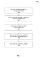
- FIG. 4 is a flow chart illustrating a method 400 for assembling an apparatus for removing a modular electronic device from a chassis, in accordance to some example embodiments.
- the method 400 may commence at operation 402 with slidably engaging a sliding element with a door.
- the door may be coupled to a first ejection actuator.
- the door may be connected with an ejection lever, and the ejection lever may be coupled to the first ejection actuator by means of a connecting element.
- the door may be pivotally coupled to the chassis in front of a chassis enclosure.
- Method 400 may proceed with disposing a second ejection actuator in a rear of the chassis enclosure at operation 408 .
- the second ejection actuator may be connected to a spring member having a first spring member end and a second spring member end, where the first spring member end may be connected to the second ejection actuator, and the second spring member end may be connected to the rear of the chassis at operation 410 .
- a linkage element having a first linkage element end and second linkage element end may be connected, by the first linkage element end, to the sliding element and, by the second linkage element end, to the second ejection actuator.
- the linkage element may be laid through a point of pivotal coupling of the door to the chassis at operation 414 .
- a length of the ejection lever may be variable to regulate a force of ejection of the modular electronic device.
- the method 400 may optionally proceed with disposing at least one guide rail in the chassis enclosure to guide the modular electronic device.
- the second ejection actuator may be electronically coupled to at least one sensing means configured to alert a user to a complete or an incomplete insertion or a removal of the modular electronic device.
- the second ejection actuator may be mechanized with an electric motor.
- FIG. 5A shows a diagrammatic representation 500 of an insertion of a modular electronic device 115 into a chassis 105 , in accordance to some example embodiments.
- a door 120 of an apparatus for removing a modular electronic device may be opened and the modular electronic device 115 may be inserted into an opening of the chassis 105 .
- the modular electronic device 115 may be pushed in a direction towards a rear of the chassis 105 until the modular electronic device 115 is inserted completely into the chassis 105 .
- the door 120 may be rotated around a point of pivotal coupling of the door 120 to the chassis 105 from an open position shown on FIG.
- a locking member (not shown) may be locked to lock the door 120 in an engaged position with the chassis 105 .
- FIG. 5B shows a diagrammatic representation 510 of a removal of a modular electronic device 115 from a chassis 105 , in accordance to some example embodiments.
- a locking member (not shown) may be unlocked to unlock the door 120 from an engaged position with the chassis 105 .
- the door 120 may be rotated around a point of pivotal coupling of the door 120 to the chassis 105 from a closed position to an open position, when the door 120 may allow removal of the modular electronic device 115 from the chassis 105 .
- the door 120 is shown in the open position.
- Rotation of the door 120 coupled with a first ejection actuator (not shown) via an ejection lever (not shown) and a connecting element (not shown), may cause movement of the first ejection actuator from the rear of the chassis enclosure towards an opening for insertion of the modular electronic device 115 .
- the first ejection actuator may push the modular electronic device 115 in the chassis enclosure in a direction towards the opening for insertion of the modular electronic device 115 .
- Pushing the modular electronic device 115 may result in decoupling the modular electronic device 115 from a connector in a rear of the chassis enclosure coupling the modular electronic device 115 with the chassis 105 .
- the sliding element 125 may be pulled in a direction along the door 120 away from the chassis enclosure.
- Movement of the sliding element 125 may cause movement of the second ejection actuator. While moving, the second ejection actuator may push the modular electronic device 115 in the chassis enclosure in a direction towards the opening for removal of the modular electronic device 115 . Pushing the modular electronic device 115 may result in moving the modular electronic device 115 along the chassis enclosure in the direction towards the opening for removal of the modular electronic device 115 .
- the modular electronic device 115 When the modular electronic device 115 extends out from the chassis for a length enough to take the modular electronic device 115 , the modular electronic device 115 may be taken and removed from the chassis 105 .
- the sliding element 125 After the ejection of the modular electronic device, the sliding element 125 may be released. After releasing the sliding element 125 , in view of connection of the second ejection actuator to a spring member connected by one end of the spring member to the rear of the chassis, the spring member may enable restoration of the second ejection actuator to an initial position in the chassis enclosure.
- FIG. 6 is a flow chart illustrating a method 600 for using an apparatus for removing a modular electronic device from a chassis, in accordance to some example embodiments.
- the method 600 may optionally commence with moving a locking member in slidable engagement with a door to unlock the door from an engaged position with the chassis at operation 602 .
- the door may be rotated around a point of pivotal coupling of the door to the chassis to an open position, when the door allows removal of the modular electronic device from the chassis.
- Rotation of the door, coupled with a first ejection actuator may cause movement of the first ejection actuator along the chassis in a direction towards the opening for insertion of the modular electronic device.
- the first ejection actuator while moving, may push the modular electronic device in a direction of movement of the first ejection actuator resulting in decoupling of the modular electronic device from the chassis.
- the method 600 may proceed with operation 606 of sliding the sliding element along the door in a direction away from the chassis enclosure (i.e., pulling the sliding element in a direction towards a person who is removing the modular electronic device).
- a force of ejection of the modular electronic device may be optionally regulated by regulating a force of pulling the sliding element along the door. The higher the force of pulling the sliding element, the higher the force of ejection of the modular electronic device from the chassis.
- Pulling the sliding element coupled with a second ejection actuator by means of a linkage element, may cause movement of the second ejection actuator along the chassis in a direction towards the opening for insertion of the modular electronic device.
- the second ejection actuator while moving, may push the modular electronic device in a direction of movement of the second ejection actuator resulting in ejection of the modular electronic device from the chassis.
- the sliding element may be released. Releasing the sliding element may result in restoring the second ejection actuator to an initial position of the second ejection actuator in the chassis enclosure by means of a spring member connected to the second ejection actuator and the rear of the chassis.
Abstract
Description
Claims (16)
Priority Applications (4)
| Application Number | Priority Date | Filing Date | Title |
|---|---|---|---|
| US13/900,358 US9389651B2 (en) | 2013-05-22 | 2013-05-22 | Modular electronics chassis |
| JP2016515100A JP2016526296A (en) | 2013-05-22 | 2014-05-22 | Modular electronic chassis |
| EP14801151.3A EP3000289A4 (en) | 2013-05-22 | 2014-05-22 | Modular electronics chassis |
| PCT/US2014/039214 WO2014190192A2 (en) | 2013-05-22 | 2014-05-22 | Modular electronics chassis |
Applications Claiming Priority (1)
| Application Number | Priority Date | Filing Date | Title |
|---|---|---|---|
| US13/900,358 US9389651B2 (en) | 2013-05-22 | 2013-05-22 | Modular electronics chassis |
Publications (2)
| Publication Number | Publication Date |
|---|---|
| US20140345105A1 US20140345105A1 (en) | 2014-11-27 |
| US9389651B2 true US9389651B2 (en) | 2016-07-12 |
Family
ID=51934351
Family Applications (1)
| Application Number | Title | Priority Date | Filing Date |
|---|---|---|---|
| US13/900,358 Active 2034-04-02 US9389651B2 (en) | 2013-05-22 | 2013-05-22 | Modular electronics chassis |
Country Status (4)
| Country | Link |
|---|---|
| US (1) | US9389651B2 (en) |
| EP (1) | EP3000289A4 (en) |
| JP (1) | JP2016526296A (en) |
| WO (1) | WO2014190192A2 (en) |
Cited By (8)
| Publication number | Priority date | Publication date | Assignee | Title |
|---|---|---|---|---|
| TWI586249B (en) * | 2016-08-18 | 2017-06-01 | 緯創資通股份有限公司 | Server device |
| US20170257968A1 (en) * | 2015-02-26 | 2017-09-07 | Dell Products L.P. | Variable-depth multi device chassis |
| US10126786B2 (en) * | 2015-07-30 | 2018-11-13 | Western Digital Technologies, Inc. | Ejection mechanism assembly for storage drive and storage drive having the ejection mechanism assembly |
| US10692541B2 (en) | 2018-06-14 | 2020-06-23 | Seagate Technology Llc | Carrierless drive insertion, retention and removal system |
| US11337329B2 (en) * | 2020-06-24 | 2022-05-17 | Dell Products, L.P. | Single-blade air damper for rack-mounted chassis |
| US20220167520A1 (en) * | 2020-11-20 | 2022-05-26 | Lenovo Enterprise Solutions (Singapore) Pte. Ltd. | Computing device rack and retaining system |
| US20220390981A1 (en) * | 2019-03-29 | 2022-12-08 | Anthony, Inc. | Door for mounting a removable electronic display |
| US11942004B2 (en) | 2018-01-17 | 2024-03-26 | Anthony, Inc. | Door for mounting a removable electronic display |
Families Citing this family (23)
| Publication number | Priority date | Publication date | Assignee | Title |
|---|---|---|---|---|
| US9628438B2 (en) | 2012-04-06 | 2017-04-18 | Exablox | Consistent ring namespaces facilitating data storage and organization in network infrastructures |
| US9552382B2 (en) | 2013-04-23 | 2017-01-24 | Exablox Corporation | Reference counter integrity checking |
| US9389651B2 (en) | 2013-05-22 | 2016-07-12 | Exablox Corporation | Modular electronics chassis |
| EP3008647A4 (en) | 2013-06-12 | 2017-01-25 | Exablox Corporation | Hybrid garbage collection |
| US9715521B2 (en) | 2013-06-19 | 2017-07-25 | Storagecraft Technology Corporation | Data scrubbing in cluster-based storage systems |
| US9128680B2 (en) * | 2013-06-27 | 2015-09-08 | Cal-Comp Electronics & Communications Company Limited | Casing structure and electronic device using the same |
| USD750033S1 (en) | 2013-07-10 | 2016-02-23 | Exablox Corporation | Modular electronics chassis |
| US8991950B2 (en) * | 2013-07-10 | 2015-03-31 | Exablox Corporation | Modular electronics chassis |
| US9934242B2 (en) | 2013-07-10 | 2018-04-03 | Exablox Corporation | Replication of data between mirrored data sites |
| US10248556B2 (en) | 2013-10-16 | 2019-04-02 | Exablox Corporation | Forward-only paged data storage management where virtual cursor moves in only one direction from header of a session to data field of the session |
| US9985829B2 (en) | 2013-12-12 | 2018-05-29 | Exablox Corporation | Management and provisioning of cloud connected devices |
| US9774582B2 (en) | 2014-02-03 | 2017-09-26 | Exablox Corporation | Private cloud connected device cluster architecture |
| JP2017504924A (en) | 2014-02-04 | 2017-02-09 | エグザブロックス・コーポレーション | Content-based organization of the file system |
| US20170060924A1 (en) | 2015-08-26 | 2017-03-02 | Exablox Corporation | B-Tree Based Data Model for File Systems |
| US9992904B2 (en) * | 2015-09-24 | 2018-06-05 | Quanta Computer Inc. | Electronic device enclosure with an access mechanism |
| US9658658B2 (en) * | 2015-10-21 | 2017-05-23 | Adlink Technology Inc. | Data storage device mounting structure |
| TWM522487U (en) * | 2015-12-25 | 2016-05-21 | Fivetech Technology Inc | Pulling assistance device and machine plate module with pulling assistance function |
| US11039546B2 (en) | 2015-12-25 | 2021-06-15 | Ting-Jui Wang | Pull-out aiding device and chassis-wall module with pull-out aiding function |
| US9846553B2 (en) | 2016-05-04 | 2017-12-19 | Exablox Corporation | Organization and management of key-value stores |
| US9939857B1 (en) * | 2017-03-20 | 2018-04-10 | Hewlett Packard Enterprise Development Lp | Chassis and hard drive |
| US10405453B1 (en) * | 2018-06-07 | 2019-09-03 | Dell Products L.P. | Systems and methods for carrier-less storage device extraction in an information handling system |
| CN114080132B (en) * | 2020-08-17 | 2023-10-13 | 富联精密电子(天津)有限公司 | Data storage device fixing structure and cabinet |
| CN112037826A (en) * | 2020-09-27 | 2020-12-04 | 记忆科技(深圳)有限公司 | Structure convenient for hard disk maintenance and hard disk maintenance method |
Citations (35)
| Publication number | Priority date | Publication date | Assignee | Title |
|---|---|---|---|---|
| US4614389A (en) | 1985-06-17 | 1986-09-30 | At&T Bell Laboratories | Circuit board assembly for accurate insertion |
| US5398141A (en) | 1991-06-28 | 1995-03-14 | Syquest Technology, Inc. | Removable cartridge disk drive with a 2.5 inch form factor utilizing a cartridge having a rotatable disk access door |
| US5483419A (en) * | 1991-09-24 | 1996-01-09 | Teac Corporation | Hot-swappable multi-cartridge docking module |
| US5597316A (en) | 1994-12-07 | 1997-01-28 | Berg Technology, Inc. | Memory card connector having improved eject mechanism and method of use |
| USD381637S (en) | 1996-02-29 | 1997-07-29 | Hughes Electronics | Electronic circuitry housing panel |
| USD393637S (en) | 1997-03-05 | 1998-04-21 | Zenith Electronics Corporation | Television set top decoder box |
| US6134116A (en) | 1999-04-27 | 2000-10-17 | Dell Usa, L. P. | Apparatus and method for latching a door in a computer system |
| US6157540A (en) | 1998-07-27 | 2000-12-05 | Dell Usa, L.P. | Screwless front loading hard drive bracket |
| US6210188B1 (en) | 1998-12-24 | 2001-04-03 | Hon Hai Precision Ind. Co., Ltd. | Electrical card connector having a card ejection mechanism |
| US6270174B1 (en) | 1999-07-05 | 2001-08-07 | Fujitsu Limited | Case for electronic equipment |
| US20020008932A1 (en) | 1998-01-20 | 2002-01-24 | Brent R. Bateman | Gateway actuator |
| US6351374B1 (en) | 1996-08-19 | 2002-02-26 | Raymond C. Sherry | Removable hard disk drive module |
| US6411505B1 (en) | 1999-11-12 | 2002-06-25 | Apple Computer, Inc. | Computer housing for a portable computer |
| USD464044S1 (en) | 2001-03-16 | 2002-10-08 | Industrial Technology Research Institute | VOIP access gateway |
| US6506065B1 (en) | 1998-02-12 | 2003-01-14 | Ergo Mechanical Systems, Incorporated | Refined rack-and-panel construction with self-locking connectors; and method of use |
| USD475681S1 (en) | 2002-05-06 | 2003-06-10 | Cyber Power System Inc. | Panel for a power supply device |
| US6587350B1 (en) | 2002-05-16 | 2003-07-01 | Inventec Corporation | Ejection mechanism for modular electronic element |
| US6798650B2 (en) | 1997-08-04 | 2004-09-28 | Sun Microsystems, Inc. | Disk drive bracket |
| US20050030721A1 (en) | 2002-08-09 | 2005-02-10 | Tsutomu Shimada | Electronic apparatus and information processing apparatus |
| US7172441B2 (en) | 2004-06-21 | 2007-02-06 | Southco, Inc. | Ejector lever assembly |
| USD553616S1 (en) | 2006-04-07 | 2007-10-23 | Sun Microsystems, Inc. | Thin rack server |
| US20090016009A1 (en) | 2007-04-13 | 2009-01-15 | Data Robotics Incorporated | Carrierless Storage System Enclosure with Ejection Mechanism |
| USD593562S1 (en) | 2008-10-13 | 2009-06-02 | Dell Products L.P. | Bezel for information handling system housing |
| US7559781B2 (en) | 2006-09-18 | 2009-07-14 | Datastore Technology Co., Ltd. | Disk-mounting assembly for mounting removably a disk drive in an electronic device |
| US7559782B2 (en) | 2006-10-20 | 2009-07-14 | Datastore Technology Co., Ltd. | Storage device box |
| USD599789S1 (en) | 2008-12-24 | 2009-09-08 | Clarion Co., Ltd. | Digital audio player |
| USD612330S1 (en) | 2009-10-09 | 2010-03-23 | Dell Products L.P. | Power supply bezel |
| US8045326B1 (en) | 2004-07-01 | 2011-10-25 | Oracle America Inc. | Hard disk drive bracket |
| US20110299237A1 (en) | 2010-06-03 | 2011-12-08 | Wen-Peng Liang | Multi-level hard drive enclosure |
| US8077467B2 (en) | 2009-01-05 | 2011-12-13 | Hong Fu Jin Precision Industry (Shenzhen) Co., Ltd. | Mounting apparatus for disk drive |
| US8203851B2 (en) | 2009-02-09 | 2012-06-19 | Juniper Networks, Inc. | Retention-extraction device for removable cards in a chassis |
| US20120218705A1 (en) * | 2011-02-25 | 2012-08-30 | Jui-Shu Huang | Removable hard disk drive bay |
| US8355256B2 (en) | 2009-08-28 | 2013-01-15 | Hong Fu Jin Precision Industry (Shenzhen) Co., Ltd. | Mounting apparatus for data storage device |
| WO2014190192A2 (en) | 2013-05-22 | 2014-11-27 | Exablox Corporation | Modular electronics chassis |
| WO2015006373A1 (en) | 2013-07-10 | 2015-01-15 | Exablox Corporation | Modular electronics chassis |
Family Cites Families (6)
| Publication number | Priority date | Publication date | Assignee | Title |
|---|---|---|---|---|
| JPH0342513Y2 (en) * | 1984-09-19 | 1991-09-05 | ||
| JPH0254388A (en) * | 1988-08-19 | 1990-02-23 | Fuji Photo Film Co Ltd | Memory cartridge attaching/detaching mechanism |
| US5831820A (en) * | 1996-12-30 | 1998-11-03 | Huang; James | Peripheral docking module using a shape memory alloy actuator wire |
| JP3140594U (en) * | 2008-01-21 | 2008-04-03 | 株式会社オウルテック | Case for hard disk drive |
| CN201255998Y (en) * | 2008-09-09 | 2009-06-10 | 黄睿树 | Hard disk withdrawn mechanism |
| TW201225073A (en) * | 2010-12-14 | 2012-06-16 | Cal Comp Electronics & Comm Co | Hard disc device |
-
2013
- 2013-05-22 US US13/900,358 patent/US9389651B2/en active Active
-
2014
- 2014-05-22 JP JP2016515100A patent/JP2016526296A/en active Pending
- 2014-05-22 WO PCT/US2014/039214 patent/WO2014190192A2/en active Application Filing
- 2014-05-22 EP EP14801151.3A patent/EP3000289A4/en not_active Withdrawn
Patent Citations (38)
| Publication number | Priority date | Publication date | Assignee | Title |
|---|---|---|---|---|
| US4614389A (en) | 1985-06-17 | 1986-09-30 | At&T Bell Laboratories | Circuit board assembly for accurate insertion |
| US5398141A (en) | 1991-06-28 | 1995-03-14 | Syquest Technology, Inc. | Removable cartridge disk drive with a 2.5 inch form factor utilizing a cartridge having a rotatable disk access door |
| US5483419A (en) * | 1991-09-24 | 1996-01-09 | Teac Corporation | Hot-swappable multi-cartridge docking module |
| US5597316A (en) | 1994-12-07 | 1997-01-28 | Berg Technology, Inc. | Memory card connector having improved eject mechanism and method of use |
| USD381637S (en) | 1996-02-29 | 1997-07-29 | Hughes Electronics | Electronic circuitry housing panel |
| US6351374B1 (en) | 1996-08-19 | 2002-02-26 | Raymond C. Sherry | Removable hard disk drive module |
| USD393637S (en) | 1997-03-05 | 1998-04-21 | Zenith Electronics Corporation | Television set top decoder box |
| US6798650B2 (en) | 1997-08-04 | 2004-09-28 | Sun Microsystems, Inc. | Disk drive bracket |
| US20020008932A1 (en) | 1998-01-20 | 2002-01-24 | Brent R. Bateman | Gateway actuator |
| US6506065B1 (en) | 1998-02-12 | 2003-01-14 | Ergo Mechanical Systems, Incorporated | Refined rack-and-panel construction with self-locking connectors; and method of use |
| US6157540A (en) | 1998-07-27 | 2000-12-05 | Dell Usa, L.P. | Screwless front loading hard drive bracket |
| US6210188B1 (en) | 1998-12-24 | 2001-04-03 | Hon Hai Precision Ind. Co., Ltd. | Electrical card connector having a card ejection mechanism |
| US6134116A (en) | 1999-04-27 | 2000-10-17 | Dell Usa, L. P. | Apparatus and method for latching a door in a computer system |
| US6270174B1 (en) | 1999-07-05 | 2001-08-07 | Fujitsu Limited | Case for electronic equipment |
| US6411505B1 (en) | 1999-11-12 | 2002-06-25 | Apple Computer, Inc. | Computer housing for a portable computer |
| USD464044S1 (en) | 2001-03-16 | 2002-10-08 | Industrial Technology Research Institute | VOIP access gateway |
| USD475681S1 (en) | 2002-05-06 | 2003-06-10 | Cyber Power System Inc. | Panel for a power supply device |
| US6587350B1 (en) | 2002-05-16 | 2003-07-01 | Inventec Corporation | Ejection mechanism for modular electronic element |
| US20050030721A1 (en) | 2002-08-09 | 2005-02-10 | Tsutomu Shimada | Electronic apparatus and information processing apparatus |
| US7172441B2 (en) | 2004-06-21 | 2007-02-06 | Southco, Inc. | Ejector lever assembly |
| US8045326B1 (en) | 2004-07-01 | 2011-10-25 | Oracle America Inc. | Hard disk drive bracket |
| USD553616S1 (en) | 2006-04-07 | 2007-10-23 | Sun Microsystems, Inc. | Thin rack server |
| US7559781B2 (en) | 2006-09-18 | 2009-07-14 | Datastore Technology Co., Ltd. | Disk-mounting assembly for mounting removably a disk drive in an electronic device |
| US7559782B2 (en) | 2006-10-20 | 2009-07-14 | Datastore Technology Co., Ltd. | Storage device box |
| US20090016009A1 (en) | 2007-04-13 | 2009-01-15 | Data Robotics Incorporated | Carrierless Storage System Enclosure with Ejection Mechanism |
| USD593562S1 (en) | 2008-10-13 | 2009-06-02 | Dell Products L.P. | Bezel for information handling system housing |
| USD599789S1 (en) | 2008-12-24 | 2009-09-08 | Clarion Co., Ltd. | Digital audio player |
| US8077467B2 (en) | 2009-01-05 | 2011-12-13 | Hong Fu Jin Precision Industry (Shenzhen) Co., Ltd. | Mounting apparatus for disk drive |
| US8203851B2 (en) | 2009-02-09 | 2012-06-19 | Juniper Networks, Inc. | Retention-extraction device for removable cards in a chassis |
| US8355256B2 (en) | 2009-08-28 | 2013-01-15 | Hong Fu Jin Precision Industry (Shenzhen) Co., Ltd. | Mounting apparatus for data storage device |
| USD612330S1 (en) | 2009-10-09 | 2010-03-23 | Dell Products L.P. | Power supply bezel |
| US20110299237A1 (en) | 2010-06-03 | 2011-12-08 | Wen-Peng Liang | Multi-level hard drive enclosure |
| US20120218705A1 (en) * | 2011-02-25 | 2012-08-30 | Jui-Shu Huang | Removable hard disk drive bay |
| US8369080B2 (en) | 2011-02-25 | 2013-02-05 | Jui-Shu Huang | Removable hard disk drive bay |
| WO2014190192A2 (en) | 2013-05-22 | 2014-11-27 | Exablox Corporation | Modular electronics chassis |
| WO2015006373A1 (en) | 2013-07-10 | 2015-01-15 | Exablox Corporation | Modular electronics chassis |
| US20150015131A1 (en) | 2013-07-10 | 2015-01-15 | Exablox Corporation | Modular Electronics Chassis |
| US8991950B2 (en) | 2013-07-10 | 2015-03-31 | Exablox Corporation | Modular electronics chassis |
Non-Patent Citations (4)
| Title |
|---|
| International Search Report dated Mar. 27, 2015 6367PCT Application No. PCT/US2014/039214. |
| International Search Report dated Oct. 27, 2014 6357PCT Application No. PCT/US2014/045824. |
| Notice of Allowance dated Aug. 29, 2014 for Japanese Design Application 342/2014. |
| OHIM-Design 002382549-0003 of 10.01.2014 |
Cited By (11)
| Publication number | Priority date | Publication date | Assignee | Title |
|---|---|---|---|---|
| US20170257968A1 (en) * | 2015-02-26 | 2017-09-07 | Dell Products L.P. | Variable-depth multi device chassis |
| US10499526B2 (en) * | 2015-02-26 | 2019-12-03 | Dell Products L.P. | Variable-depth multi device chassis |
| US10126786B2 (en) * | 2015-07-30 | 2018-11-13 | Western Digital Technologies, Inc. | Ejection mechanism assembly for storage drive and storage drive having the ejection mechanism assembly |
| TWI586249B (en) * | 2016-08-18 | 2017-06-01 | 緯創資通股份有限公司 | Server device |
| US9930804B2 (en) | 2016-08-18 | 2018-03-27 | Wistron Corp. | Server device |
| US11942004B2 (en) | 2018-01-17 | 2024-03-26 | Anthony, Inc. | Door for mounting a removable electronic display |
| US10692541B2 (en) | 2018-06-14 | 2020-06-23 | Seagate Technology Llc | Carrierless drive insertion, retention and removal system |
| US20220390981A1 (en) * | 2019-03-29 | 2022-12-08 | Anthony, Inc. | Door for mounting a removable electronic display |
| US11947384B2 (en) * | 2019-03-29 | 2024-04-02 | Anthony, Inc. | Door for mounting a removable electronic display |
| US11337329B2 (en) * | 2020-06-24 | 2022-05-17 | Dell Products, L.P. | Single-blade air damper for rack-mounted chassis |
| US20220167520A1 (en) * | 2020-11-20 | 2022-05-26 | Lenovo Enterprise Solutions (Singapore) Pte. Ltd. | Computing device rack and retaining system |
Also Published As
| Publication number | Publication date |
|---|---|
| EP3000289A4 (en) | 2017-01-11 |
| WO2014190192A3 (en) | 2015-06-04 |
| US20140345105A1 (en) | 2014-11-27 |
| WO2014190192A2 (en) | 2014-11-27 |
| EP3000289A2 (en) | 2016-03-30 |
| JP2016526296A (en) | 2016-09-01 |
Similar Documents
| Publication | Publication Date | Title |
|---|---|---|
| US9389651B2 (en) | Modular electronics chassis | |
| US8991950B2 (en) | Modular electronics chassis | |
| US6621692B1 (en) | Computerized system having an interface apparatus with improved mounting features | |
| US5325263A (en) | Rack and pinion retaining and release device for removable computer components | |
| US5269698A (en) | Retaining and release mechanism for computer storage devices including a pawl latch assembly | |
| TWI612519B (en) | Compact tool-less hard drive disk carrier and computing device | |
| US8023263B2 (en) | Latch for securing a hardware component into a component bay | |
| US8743536B2 (en) | Mechanical conversion sleeve | |
| US20060250766A1 (en) | Apparatus for removably securing storage components in an enclosure | |
| TWI352770B (en) | Latch for connecting a component to a device | |
| US20110139735A1 (en) | Retaining apparatus for data storage device | |
| US20110249392A1 (en) | Computer Including Hot-pluggable Disk Storage Drives That Are Mounted In An In-line Arrangement | |
| US10015892B1 (en) | Disk drive holding mechanism and server using the same | |
| US20210132668A1 (en) | Storage drive carrier for high-density storage solution | |
| CN108345361A (en) | Hard disk bearing device and computer apparatus | |
| WO2017063436A1 (en) | Subrack locking mechanism and power supply cabinet | |
| TW201413710A (en) | External enclosure for storage device | |
| US8614894B2 (en) | Electronic device assembly having protecting mechanism | |
| US8817463B1 (en) | Electronics rack with a movable power distribution unit | |
| US20110007472A1 (en) | Cable management module | |
| US20190108860A1 (en) | Tool-less mounting apparatus for hard disk drive and storage device using the same | |
| US20120013233A1 (en) | Chassis module without using securing tool | |
| US9964997B2 (en) | Locking bar for a computer | |
| TW201630515A (en) | Latching system | |
| US8824131B2 (en) | Disk drive mounting assembly |
Legal Events
| Date | Code | Title | Description |
|---|---|---|---|
| AS | Assignment |
Owner name: EXABLOX CORPORATION, CALIFORNIA Free format text: ASSIGNMENT OF ASSIGNORS INTEREST;ASSIGNOR:BROCKETT, DOUGLAS;REEL/FRAME:035452/0387 Effective date: 20130522 |
|
| STCF | Information on status: patent grant |
Free format text: PATENTED CASE |
|
| AS | Assignment |
Owner name: SILICON VALLEY BANK, AS ADMINISTRATIVE AGENT, CALI Free format text: SECURITY INTEREST;ASSIGNORS:EXABLOX CORPORATION;STORAGECRAFT INTERMEDIATE HOLDINGS, INC.;STORAGECRAFT ACQUISITION CORPORATION;AND OTHERS;REEL/FRAME:041748/0849 Effective date: 20170324 |
|
| FEPP | Fee payment procedure |
Free format text: ENTITY STATUS SET TO UNDISCOUNTED (ORIGINAL EVENT CODE: BIG.); ENTITY STATUS OF PATENT OWNER: LARGE ENTITY |
|
| MAFP | Maintenance fee payment |
Free format text: PAYMENT OF MAINTENANCE FEE, 4TH YEAR, LARGE ENTITY (ORIGINAL EVENT CODE: M1551); ENTITY STATUS OF PATENT OWNER: LARGE ENTITY Year of fee payment: 4 |
|
| AS | Assignment |
Owner name: EXABLOX CORPORATION, CALIFORNIA Free format text: ASSIGNMENT OF ASSIGNORS INTEREST;ASSIGNORS:PRIVITERA, PETER;CARVER, JON;DRUKER, JOSHUA;AND OTHERS;SIGNING DATES FROM 20130617 TO 20130709;REEL/FRAME:055182/0617 |
|
| AS | Assignment |
Owner name: MONROE CAPITAL MANAGEMENT ADVISORS, LLC, AS COLLATERAL AGENT, ILLINOIS Free format text: SECURITY INTEREST;ASSIGNORS:ARCSERVE (USA) LLC;STORAGECRAFT TECHNOLOGY LLC;ZETTA, LLC;REEL/FRAME:055603/0219 Effective date: 20210316 Owner name: EXABLOX CORPORATION, MINNESOTA Free format text: TERMINATION AND RELEASE OF PATENT SECURITY AGREEMENT;ASSIGNOR:SILICON VALLEY BANK, AS ADMINISTRATIVE AGENT;REEL/FRAME:055614/0852 Effective date: 20210316 Owner name: STORAGECRAFT TECHNOLOGY CORPORATION, MINNESOTA Free format text: TERMINATION AND RELEASE OF PATENT SECURITY AGREEMENT;ASSIGNOR:SILICON VALLEY BANK, AS ADMINISTRATIVE AGENT;REEL/FRAME:055614/0852 Effective date: 20210316 Owner name: STORAGECRAFT ACQUISITION CORPORATION, MINNESOTA Free format text: TERMINATION AND RELEASE OF PATENT SECURITY AGREEMENT;ASSIGNOR:SILICON VALLEY BANK, AS ADMINISTRATIVE AGENT;REEL/FRAME:055614/0852 Effective date: 20210316 Owner name: STORAGECRAFT INTERMEDIATE HOLDINGS, INC., MINNESOTA Free format text: TERMINATION AND RELEASE OF PATENT SECURITY AGREEMENT;ASSIGNOR:SILICON VALLEY BANK, AS ADMINISTRATIVE AGENT;REEL/FRAME:055614/0852 Effective date: 20210316 |
|
| MAFP | Maintenance fee payment |
Free format text: PAYMENT OF MAINTENANCE FEE, 8TH YEAR, LARGE ENTITY (ORIGINAL EVENT CODE: M1552); ENTITY STATUS OF PATENT OWNER: LARGE ENTITY Year of fee payment: 8 |