US9368888B2 - Electrical connector with a screwing member to fix a load plate to a housing - Google Patents
Electrical connector with a screwing member to fix a load plate to a housing Download PDFInfo
- Publication number
- US9368888B2 US9368888B2 US14/645,785 US201514645785A US9368888B2 US 9368888 B2 US9368888 B2 US 9368888B2 US 201514645785 A US201514645785 A US 201514645785A US 9368888 B2 US9368888 B2 US 9368888B2
- Authority
- US
- United States
- Prior art keywords
- load plate
- screwing member
- electrical connector
- insulating housing
- fixing hole
- Prior art date
- Legal status (The legal status is an assumption and is not a legal conclusion. Google has not performed a legal analysis and makes no representation as to the accuracy of the status listed.)
- Active
Links
- 238000000034 method Methods 0.000 claims abstract description 4
- 230000000149 penetrating effect Effects 0.000 claims description 2
- WEJZHZJJXPXXMU-UHFFFAOYSA-N 2,4-dichloro-1-phenylbenzene Chemical compound ClC1=CC(Cl)=CC=C1C1=CC=CC=C1 WEJZHZJJXPXXMU-UHFFFAOYSA-N 0.000 description 3
- ZHBBDTRJIVXKEX-UHFFFAOYSA-N 1-chloro-2-(3-chlorophenyl)benzene Chemical compound ClC1=CC=CC(C=2C(=CC=CC=2)Cl)=C1 ZHBBDTRJIVXKEX-UHFFFAOYSA-N 0.000 description 2
- 239000000758 substrate Substances 0.000 description 2
- 238000012986 modification Methods 0.000 description 1
- 230000004048 modification Effects 0.000 description 1
Images


Classifications
-
- H—ELECTRICITY
- H01—ELECTRIC ELEMENTS
- H01R—ELECTRICALLY-CONDUCTIVE CONNECTIONS; STRUCTURAL ASSOCIATIONS OF A PLURALITY OF MUTUALLY-INSULATED ELECTRICAL CONNECTING ELEMENTS; COUPLING DEVICES; CURRENT COLLECTORS
- H01R12/00—Structural associations of a plurality of mutually-insulated electrical connecting elements, specially adapted for printed circuits, e.g. printed circuit boards [PCB], flat or ribbon cables, or like generally planar structures, e.g. terminal strips, terminal blocks; Coupling devices specially adapted for printed circuits, flat or ribbon cables, or like generally planar structures; Terminals specially adapted for contact with, or insertion into, printed circuits, flat or ribbon cables, or like generally planar structures
- H01R12/70—Coupling devices
- H01R12/7005—Guiding, mounting, polarizing or locking means; Extractors
- H01R12/7011—Locking or fixing a connector to a PCB
- H01R12/7058—Locking or fixing a connector to a PCB characterised by the movement, e.g. pivoting, camming or translating parallel to the PCB
-
- H—ELECTRICITY
- H01—ELECTRIC ELEMENTS
- H01R—ELECTRICALLY-CONDUCTIVE CONNECTIONS; STRUCTURAL ASSOCIATIONS OF A PLURALITY OF MUTUALLY-INSULATED ELECTRICAL CONNECTING ELEMENTS; COUPLING DEVICES; CURRENT COLLECTORS
- H01R12/00—Structural associations of a plurality of mutually-insulated electrical connecting elements, specially adapted for printed circuits, e.g. printed circuit boards [PCB], flat or ribbon cables, or like generally planar structures, e.g. terminal strips, terminal blocks; Coupling devices specially adapted for printed circuits, flat or ribbon cables, or like generally planar structures; Terminals specially adapted for contact with, or insertion into, printed circuits, flat or ribbon cables, or like generally planar structures
- H01R12/70—Coupling devices
- H01R12/7005—Guiding, mounting, polarizing or locking means; Extractors
- H01R12/7011—Locking or fixing a connector to a PCB
- H01R12/7047—Locking or fixing a connector to a PCB with a fastener through a screw hole in the coupling device
-
- H—ELECTRICITY
- H01—ELECTRIC ELEMENTS
- H01R—ELECTRICALLY-CONDUCTIVE CONNECTIONS; STRUCTURAL ASSOCIATIONS OF A PLURALITY OF MUTUALLY-INSULATED ELECTRICAL CONNECTING ELEMENTS; COUPLING DEVICES; CURRENT COLLECTORS
- H01R13/00—Details of coupling devices of the kinds covered by groups H01R12/70 or H01R24/00 - H01R33/00
- H01R13/62—Means for facilitating engagement or disengagement of coupling parts or for holding them in engagement
-
- H—ELECTRICITY
- H05—ELECTRIC TECHNIQUES NOT OTHERWISE PROVIDED FOR
- H05K—PRINTED CIRCUITS; CASINGS OR CONSTRUCTIONAL DETAILS OF ELECTRIC APPARATUS; MANUFACTURE OF ASSEMBLAGES OF ELECTRICAL COMPONENTS
- H05K7/00—Constructional details common to different types of electric apparatus
- H05K7/02—Arrangements of circuit components or wiring on supporting structure
- H05K7/10—Plug-in assemblages of components, e.g. IC sockets
- H05K7/1007—Plug-in assemblages of components, e.g. IC sockets with means for increasing contact pressure at the end of engagement of coupling parts
Definitions
- the present invention relates generally to an electrical connector, and more particularly to an electrical connector having an improved load plate which can indicate a degree of the load plate being screwed onto a printed circuit board (PCB) and then prevents overstress thereby.
- PCB printed circuit board
- TW patent number M344587 issued to Yeh on Nov. 11, 2008 discloses a traditional socket connector for connecting a package to a substrate.
- the socket connector comprises an insulating housing with a plurality of contacts received therein, a positioning member near the insulating housing, a metallic cover assembled to the positioning member and covering on the insulating housing and a screw assembled to the metallic cover.
- the positioning member and the insulating housing are positioned on the substrate.
- the load plate includes a body portion and a tongue portion extending from the body portion. The tongue portion defines a hole for assembling the screw.
- the cover After the package is assembled to the insulating housing, rotate the cover to a closed position and then tight the screw to a position where the cover exerts a pressure on the package to make sure that the package stays in the socket securely.
- tight the screw there is no any cue to tell the operator that the screw has been tighten to its correct position. If the screw does not achieve its correct position, the load plate can not exert a normal force on the package, which can not ensure the connection between the contacts of the socket connector and the package. While if the screw is over-screwed, the force exerted by the load plate will damage the contacts.
- an object of the present invention is to provide an electrical connector having an improved load plate can indicate a degree of the load plate being screwed onto a printed circuit board (PCB) and then preventing overstress thereby.
- PCB printed circuit board
- an electrical connector for mounting on a printed circuit board includes an insulating housing, a plurality of contacts received in the insulating housing, a load plate covering on the insulating housing and being able to rotate between a closed position and an opened position and a screwing member assembled to the load plate and used to keep the load plate in the closed position, the screwing member includes a head portion with a plurality of tooth portions, the load plate includes a tongue portion, the tongue portion has a fixing hole for the screwing member going through, a recess near the fixing hole and a block in the recess, during the process of screwing the screwing member, the tooth portions touch with the block for making a sound.
- PCB printed circuit board
- FIG. 1 is an exploded view of an electrical connector according to the present invention
- FIG. 2 is an isometric view of the screwing member as shown in FIG. 1 ;
- FIG. 3 is an enlarged view of the circular portion of the load plate as shown in FIG. 1 ;
- FIG. 4 is an assembled view of the electrical connector and a printed circuit board (PCB);
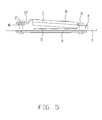
- FIG. 5 is side view of the electrical connector and the printed circuit board (PCB) as shown in FIG. 4 ;
- FIG. 6 is similar to FIG. 5 , wherein the screw is screwed to a correct position.
- an electrical connector 100 of the present invention is used for connecting a central processing unit (CPU) 8 with a printed circuit board (PCB) 7 .
- the electrical connector 100 comprises an insulating housing 5 with plurality of contacts (not shown) received therein, a fixing member 4 assembled on the PCB 7 , a load plate 3 pivotally assembled to the fixing member 4 and covering on the insulating housing 5 , a pair of fastening members 3 for assembling the fixing member 4 and the load plate 3 to the PCB 6 , a screwing member 2 assembled to the load plate 3 for assembling the load plate 3 to the PCB 6 and a ring 6 assembled to the screwing member 2 .
- the load plate 10 has a main portion 10 , a tongue portion 12 extending from a front end of the main portion 10 , and a pair of pivotal portions 13 extending toward each other from the two opposite ends of the main portion 10 .
- the tongue portion 12 defines a through fixing hole 120 , a recess 121 near the fixing hole 120 and a block or protrusion 1210 in the recess 121 .
- the fixing member 4 includes a body portion 40 and a pair of L shaped slot 401 on two ends thereof and a pair of through holes 402 penetrating the body portion 40 of the fixing member 4 .
- the screwing member 2 includes a head portion 20 , an assembling portion 21 extending downwardly from the head portion 20 and a matching portion 22 extending downwardly from the assembling portion 21 .
- the head portion 20 defines a plurality of tooth portions 201 .
- the fixing member 4 locates on a side of the insulating housing 5 , the pivotal portions 13 of the load plate 1 are received in the slots 401 of the fixing member 4 , the fastening members 3 go through the through holes 402 of the fixing member 4 and screw with a back plate 9 assembled under the PCB 7 , the fastening members 3 press on the pivotal portions 13 of the load plate 1 to position the load pale 1 .
- the ring 6 is assembled to the assembling portion 21 of the screwing member 2 for limiting the screwing member 2 on the load plate 1 and there is a space between the tongue portion 12 of the load plate 1 and the ring 6 . The ring 6 interferences with the assembling portion 21 of the screwing member 2 .
Abstract
Description
Claims (14)
Applications Claiming Priority (3)
| Application Number | Priority Date | Filing Date | Title |
|---|---|---|---|
| TW103108592 | 2014-03-12 | ||
| TW103108592A TW201535865A (en) | 2014-03-12 | 2014-03-12 | Electrical connector |
| TW103108592A | 2014-03-12 |
Publications (2)
| Publication Number | Publication Date |
|---|---|
| US20150263441A1 US20150263441A1 (en) | 2015-09-17 |
| US9368888B2 true US9368888B2 (en) | 2016-06-14 |
Family
ID=54069980
Family Applications (1)
| Application Number | Title | Priority Date | Filing Date |
|---|---|---|---|
| US14/645,785 Active US9368888B2 (en) | 2014-03-12 | 2015-03-12 | Electrical connector with a screwing member to fix a load plate to a housing |
Country Status (2)
| Country | Link |
|---|---|
| US (1) | US9368888B2 (en) |
| TW (1) | TW201535865A (en) |
Cited By (1)
| Publication number | Priority date | Publication date | Assignee | Title |
|---|---|---|---|---|
| US20170005425A1 (en) * | 2015-07-03 | 2017-01-05 | Lotes Co., Ltd | Electrical connector |
Citations (10)
| Publication number | Priority date | Publication date | Assignee | Title |
|---|---|---|---|---|
| US4033663A (en) * | 1975-11-03 | 1977-07-05 | Altair Tool & Engineering Inc. | Connector block and terminal assembly |
| US4085989A (en) * | 1975-11-03 | 1978-04-25 | Altair Tool & Engineering Inc. | Connector block and terminal assembly |
| US4165910A (en) * | 1977-10-25 | 1979-08-28 | Bunker Ramo Corporation | Electrical connector |
| US4497530A (en) * | 1983-07-25 | 1985-02-05 | Amp Incorporated | Electrical connector having a coupling indicator |
| US5344334A (en) * | 1993-06-11 | 1994-09-06 | The Whitaker Corporation | Hinged cover for an electrical socket |
| US6010348A (en) * | 1997-05-20 | 2000-01-04 | Alden Products Company | Field-assembled two-piece snap-fit self-sealed electrical connector |
| US6354859B1 (en) * | 1995-10-04 | 2002-03-12 | Cerprobe Corporation | Cover assembly for an IC socket |
| US20080153337A1 (en) * | 2006-12-21 | 2008-06-26 | Zuofeng Jin | Electrical connector |
| TWM344587U (en) | 2008-03-17 | 2008-11-11 | Hon Hai Prec Ind Co Ltd | Electrical connector |
| US8979565B2 (en) * | 2012-06-25 | 2015-03-17 | Hon Hai Precision Industry Co., Ltd. | Electrical connector having a holding member and a load plate pivotally assembled to two ends of a stiffener |
-
2014
- 2014-03-12 TW TW103108592A patent/TW201535865A/en unknown
-
2015
- 2015-03-12 US US14/645,785 patent/US9368888B2/en active Active
Patent Citations (10)
| Publication number | Priority date | Publication date | Assignee | Title |
|---|---|---|---|---|
| US4033663A (en) * | 1975-11-03 | 1977-07-05 | Altair Tool & Engineering Inc. | Connector block and terminal assembly |
| US4085989A (en) * | 1975-11-03 | 1978-04-25 | Altair Tool & Engineering Inc. | Connector block and terminal assembly |
| US4165910A (en) * | 1977-10-25 | 1979-08-28 | Bunker Ramo Corporation | Electrical connector |
| US4497530A (en) * | 1983-07-25 | 1985-02-05 | Amp Incorporated | Electrical connector having a coupling indicator |
| US5344334A (en) * | 1993-06-11 | 1994-09-06 | The Whitaker Corporation | Hinged cover for an electrical socket |
| US6354859B1 (en) * | 1995-10-04 | 2002-03-12 | Cerprobe Corporation | Cover assembly for an IC socket |
| US6010348A (en) * | 1997-05-20 | 2000-01-04 | Alden Products Company | Field-assembled two-piece snap-fit self-sealed electrical connector |
| US20080153337A1 (en) * | 2006-12-21 | 2008-06-26 | Zuofeng Jin | Electrical connector |
| TWM344587U (en) | 2008-03-17 | 2008-11-11 | Hon Hai Prec Ind Co Ltd | Electrical connector |
| US8979565B2 (en) * | 2012-06-25 | 2015-03-17 | Hon Hai Precision Industry Co., Ltd. | Electrical connector having a holding member and a load plate pivotally assembled to two ends of a stiffener |
Cited By (2)
| Publication number | Priority date | Publication date | Assignee | Title |
|---|---|---|---|---|
| US20170005425A1 (en) * | 2015-07-03 | 2017-01-05 | Lotes Co., Ltd | Electrical connector |
| US9717156B2 (en) * | 2015-07-03 | 2017-07-25 | Lotes Co., Ltd | Electrical socket connector with guide frame IC chip placement |
Also Published As
| Publication number | Publication date |
|---|---|
| TW201535865A (en) | 2015-09-16 |
| US20150263441A1 (en) | 2015-09-17 |
Similar Documents
| Publication | Publication Date | Title |
|---|---|---|
| US8574011B2 (en) | Electronic connector | |
| US20100061066A1 (en) | Circuit borad shield | |
| US20090191744A1 (en) | Electrical connector with improved package retention device | |
| US8162673B2 (en) | Electromagnetic interference spring contact for shielding electromagnetic interference and electronic device using same | |
| US9368888B2 (en) | Electrical connector with a screwing member to fix a load plate to a housing | |
| TWI469448B (en) | Protecting cover for connector | |
| US7753706B2 (en) | Socket connector with locking device | |
| US7826221B2 (en) | Computer chassis for mounting motherboard therein | |
| US10903590B2 (en) | Dual in-line memory module (DIMM) connector retention apparatus | |
| TW200705747A (en) | Electrical connector | |
| US8303332B2 (en) | Socket connector assembly with flexible orientation heat pipe | |
| TW201248026A (en) | Mounting apparatus | |
| US10312606B1 (en) | Cable fastening terminal block | |
| JP2017515268A5 (en) | ||
| CN105485117B (en) | A kind of connector that can be concatenated from beginning to end | |
| US8398411B2 (en) | Socket assembly incorporated with rotationally mounted pressing member | |
| US20130137309A1 (en) | Micro-connector with flatly disposed pins | |
| US10292283B2 (en) | Device with printed circuit board (PCB) | |
| TWI715730B (en) | Card edge connector | |
| US10615531B2 (en) | Socket having conductive terminals for connectors | |
| US20130240253A1 (en) | Printed circuit board with grounding protection | |
| US9312619B2 (en) | Network card fixing structure and network card module | |
| US20180239403A1 (en) | Board card module | |
| TWM471731U (en) | Fixing structure for circuit board | |
| CN210517193U (en) | Locking mechanism for LRM connector |
Legal Events
| Date | Code | Title | Description |
|---|---|---|---|
| AS | Assignment |
Owner name: FOXCONN INTERCONNECT TECHNOLOGY LIMITED, CAYMAN IS Free format text: ASSIGNMENT OF ASSIGNORS INTEREST;ASSIGNOR:YEH, CHENG-CHI;REEL/FRAME:035156/0143 Effective date: 20141124 |
|
| STCF | Information on status: patent grant |
Free format text: PATENTED CASE |
|
| MAFP | Maintenance fee payment |
Free format text: PAYMENT OF MAINTENANCE FEE, 4TH YEAR, LARGE ENTITY (ORIGINAL EVENT CODE: M1551); ENTITY STATUS OF PATENT OWNER: LARGE ENTITY Year of fee payment: 4 |
|
| MAFP | Maintenance fee payment |
Free format text: PAYMENT OF MAINTENANCE FEE, 8TH YEAR, LARGE ENTITY (ORIGINAL EVENT CODE: M1552); ENTITY STATUS OF PATENT OWNER: LARGE ENTITY Year of fee payment: 8 |